

Page 1

10BASE-T Ethernet
Mini Hubs
Models DE-809TP
DE-809TC
User’s Guide
Fifth Edit ion ( J an. 1999)
6DE809TP..05
Printed I n Ta iwan
RECYCLABLE
Page 2

WARRANTIES EXCLUSIVE
,) 7+( 'ð/,1. 352'8&7 '2(6 12 7 2 3(5$7( $6 :$55$17(' $%29(ñ 7+(
&86720(5ö6 62/( 5(0('< 6+$// %(ñ $7 'ð/,1.ö6 237,21ñ 5(3$,5 25
5(3/$&(0(17ï 7+( )25(*2,1* :$55$17,(6 $1' 5(0(',(6 $5(
(;&/86,9( $1' $5( ,1 /,(8 2) $// 27+(5 :$55$17,(6ñ (;35(66(' 25
,03/,('ñ (,7+(5 ,1 )$&7 25 %< 23(5$7,21 2) /$:ñ 67$78725< 25
27+(5:,6(ñ ,1&/8',1* :$55$17,(6 2) 0(5&+$17$%,/,7< $1'
),71(66 )25 $ 3$57,&8/$5 385326(ï 'ð/,1. 1(,7+(5 $6680(6 125
$87+25,=(6 $1< 27+(5 3(5621 72 $6680( )25 ,7 $1< 27+(5
/,$%,/,7< ,1 &21 1(&7,21 :,7+ 7+( 6$/(ñ ,167$//$7,21 0$,17(1$1&(
25 86( 2) 'ð/,1.ö6 352'8&76ï
'ð/,1. 6+$// 127 %( /,$%/( 81'(5 7+,6 :$55$17< ,) ,76 7(67,1*
$1' (;$0,1$7,21 ',6&/26( 7+$7 7+( $//(*(' '()(&7 ,1 7+(
352'8&7 '2(6 127 (;,67 25 :$6 &$86(' %< 7+( &86720(5ö6 25 $1<
7+,5' 3(5621ö6 0,686(ñ 1(*/(&7ñ ,03523(5 ,167$//$7,21 25
7(67,1*ñ 81$87+25,=(' $77(0376 72 5(3$,5ñ 25 $1< 27+(5 &$86(
%(<21' 7+( 5$1*( 2) 7+( ,17(1'(' 86(ñ 25 %< $&&,'(17ñ ),5(ñ
/,*+71,1* 25 27+(5 +$=$5'ï
LIMITATION OF LIABILITY
,1 12 (9(17 :,// 'ð/,1. %( /,$%/( )25 $1< '$0$*(6ñ ,1&/8',1 *
/266 2) '$7$ñ /266 2) 352),76ñ &267 2) &29(5 25 27+(5 ,1&,'(17$/ñ
&216(48(17,$/ 25 ,1',5(&7 '$0$*(6 $5,6,1* 287 7+(
,167$//$7,21ñ 0$,17(1$1&(ñ 86(ñ 3(5)250$1&(ñ )$,/85( 25
,17(55837,21 2) $ 'ð /,1. 352'8&7ñ +2:(9(5 &$86(' $1' 21 $1<
7+(25< 2) /,$%,/,7<ï 7+,6 /,0,7$7,21 :,// $33/< (9(1 ,) 'ð/,1. +$6
%((1 $'9,6(' 2) 7+( 3266,%,/,7< 2) 68&+ '$0$*(ï
,) <28 385&+$6(' $ 'ð/,1. 352'8&7 ,1 7+( 81,7(' 67$7(6ñ 620(
67$7(6 '2 127 $//2 : 7+( /,0,7$7,21 25 (;&/86,21 2) /,$%,/,7< )25
,1&,'(17$/ 25 &216(48(17,$/ '$0$*(6ñ 62 7+( $%29( /,0,7$7,21
0$< 127 $33/< 72 <28 ï
Limited Warranty
Hardware:
'ð/LQN ZDUUDQWV LWV KDUGZDUH SURGXFWV WR EH IUHH IURP GHIHFWV LQ ZRUNPDQVKLS DQG
PDWHULDOVñ XQGHU QRUPDO XVH DQG VHUYLFHñ IRU WKH IROORZLQJ SHULRGV PHDVXUHG IURP
GDWH RI SXUFKDVH IURP 'ð/LQN RU LWV $XWKRUL]HG 5HVHOOHUã
3URGXFW 7\SH :DUUDQW\ 3HULRG
&RPSOHWH SURGXFWV 2QH \HDU
6SDUH SDUWV DQG VSDUH NLWV äí GD\V
ii
Page 3

7KH RQHð\HDU SHULRG R I ZDUUDQW\ RQ FRPSOHWH SURGXFWV DSSOLHV RQ FRQGLWLRQ WKDW WKH
SURGXFWöV 5HJLVWUDWLRQ &DUG LV ILOOHG RXW DQG UHWXUQHG WR D 'ð/LQN RIILFH ZLWKLQ QLQHW\
õäíô GD\V RI SXUFKDVHï $ OLVW RI 'ð/LQN RIILFHV LV SURYLGHG DW WKH EDFN RI WKLV PDQXDOñ
WRJHWKHU ZLWK D FRS\ RI WKH 5HJLVWUDWLRQ &DUGï )DLOLQJ VXFK WLPHO\ UHJLVWUDWLRQ R I
SXUFKDVHñ WKH ZDUUDQW\ SHULRG VKDOO EH OLPLWHG WR äí GD\Vï
,I WKH SURGXFW SURYHV GHIHFWLYH ZLWKLQ WKH DSSOLFDEOH ZDUUDQW\ SHULRGñ 'ð/LQN ZLOO
SURYLGH UHSDLU RU UHSODFHPHQW RI WKH SURGXFWï 'ð/LQN VKDOO KDYH WKH VROH GLVFUHWLRQ
ZKHWKHU WR UHSDLU RU UHSODFHñ DQG UHSODFHPHQW SURGXFW PD\ EH QHZ RU UHFRQGLWLRQHGï
5HSODFHPHQW SURGXFW VKDOO EH RI HTXLYDOHQW RU EHWWHU VSHFLILFDWLRQVñ UHODWLYH WR WKH
GHIHFWLYH SURGXFWñ EXW QHHG QRW EH LGHQWLFDOï $Q\ SURGXFW RU SDUW UHSDLUHG E\ 'ð/LQN
SXUVXDQW WR WKLV ZDUUDQW\ VKDOO KDYH D ZDUUDQW\ SHULRG RI QRW OHVV WKDQ äí GD\Vñ IURP
GDWH RI VXFK UHSDLUñ LUUHVSHFWLYH RI DQ\ HDUOLHU H[SLUDWLRQ RI RULJLQDO ZDUUDQW\ SHULRGï
:KHQ 'ð/LQN SURYLGHV UHSODFHPHQWñ WKHQ WKH GHIHFWLYH SURGXFW EHFRPHV WKH SURSHUW\
RI 'ð/LQNï
:DUUDQW\ VHUYLFH PD\ EH REWDLQHG E\ FRQWDFWLQJ D 'ð/LQN RIILFH ZLWKLQ WKH DSSOLFDEOH
ZDUUDQW\ SHULRGñ DQG UHTXHVWLQJ D 5HWXUQ 0DWHULDO $XWKRUL]DWLRQ õ50$ô QXPEHUï ,I D
5HJLVWUDWLRQ &DUG IRU WKH SURGXFW LQ TXHVWLRQ KDV QRW EHHQ UHWXUQHG WR 'ð/LQNñ WKHQ D
SURRI RI SXUFKDVH õVXFK DV D FRS\ RI WKH GDWHG SXUFKDVH LQYRLFHô PXVW EH SURYLGHGï ,I
3XUFKDVHUöV FLUFXPVWDQFHV UHTXLUH VSHFLDO KDQGOLQJ RI ZDUUDQW\ FRUUH FWLRQñ WKHQ DW
WKH WLPH RI UHTXHVWLQJ 50$ QXPEHUñ 3XUFKDVHU PD\ DOVR SURSRVH VSHFLDO SURFHGXUH DV
PD\EHVXLWDEOHWRWKHFDVHï
$IWHU DQ 50$ QXPEHU LV LVVXHGñ WKH GHIHFWLYH SURGXFW PXVW EH SDFNDJHG VHFXUHO\ LQ
WKH RULJLQDO R U RWKHU VXLWDEOH VKLSSLQJ SDFNDJH WR HQVXUH WKDW LW ZLOO QRW EH GDPDJHG
LQ WUDQVLWñ DQG WKH 50$ QXPEHU PXVW EH SURPLQHQWO\ PDUNHG RQ WKH RXWVLGH RI WKH
SDFNDJHï 7KH SDFNDJH PXVW EH PDLOHG RU RWKHUZLVH VKLSSHG WR 'ð/LQN ZLWK DOO FRVWV RI
PDLOLQJîVKLSSLQJîLQVXUDQFH SUHSDLGâ 'ð/LQN ZLOO RUGLQDULO\ UHLPEXUVH 3XUFKDVHU IRU
PDLOLQJîVKLSSLQJîLQVXUDQFH H[SHQVHV LQFXUUHG IRU UHWXUQ RI GHIHFWLYH SURGXFW LQ
DFFRUGDQFH ZLWK WKLV ZDUUDQW\ï 'ð/LQN VKDOO QHYHU EH UHVSRQVLEOH IRU DQ\ VRIWZDUHñ
ILUPZDUHñ LQIRUPDWLRQñ RU PHPRU\ GDWD RI 3XUFKDVHU FRQWDLQHG LQñ VWRUHG RQñ RU
LQWHJUDWHG ZLWK DQ\ SURGXFW UHWXUQHG WR 'ð/LQN SXUVXDQW WR WKLV ZDUUDQW\ï
$Q\ SDFNDJH UHWXUQHG WR 'ð/LQN ZLWKRXW DQ 50$ QXPEHU ZLOO EH UHMHFWHG DQG
VKLSSHG EDFN WR 3XUFKDVHU DW 3XUFKDVHUöV H[SHQVHñ DQG 'ð/LQN UHVHUYHV WKH ULJKW LQ
VXFK D FDVH WR OHY\ D UHDVRQDEOH KDQGOLQJ FKDUJH LQ DGGLWLRQ PDLOLQJ RU VKLSSLQJ FRVWVï
D-Link Offices for Registration and Warranty
Service
7KH SURGXFWöV 5HJLVWUDWLRQ &DUGñ SURYLGHG DW WKH EDFN RI WKLV PDQXDOñ PXVW EH VHQW WR
D 'ð/LQN RIILFHï 7R REWDLQ DQ 50$ QXPEHU IRU ZDUUDQW\ VHUYLFH DV WR D KDUGZDUH
SURGXFWñ RU WR REWDLQ ZDUUDQW\ VHUYLFH DV WR D VRIWZ DUH SUR GXFWñ FR QWDFW WKH 'ð/LQN
RIILFH QHDUHVW \RXï $Q DGGUHVVHVîWHOHSKRQHîID[ OLVW RI 'ð/LQN RIILFHV LV SURYLGHG LQ WKH
EDFN RI WKLV PDQXDOï
iii
Page 4

iv
Page 5

Trademarks
&RS\ULJKWìäää 'ð/LQN &RUSRUDWLRQï
&RQWHQWV VXEMHFW WR FKDQJH ZLWKRXW SULRU QRWLFHï
'ð/LQN LV D UHJLVWHUHG WUDGHPDUN RI 'ð/LQN &RUSRUDWLRQî'ð
/LQN 6\VWHPVñ ,QFï
$OO RWKHU WUDGHPDUNV EHORQJ WR WKHLU UHVSHFWLYH SURSULHWRUVï
Copyright Statement
1R SDUW RI WKLV SXEOLFDWLRQ PD\ EH UHSURGXFHG LQ DQ\ IRUP
RU E\ DQ\ PHDQV RU XVHG WR PDNH DQ\ GHULYDWLYH VXFK DV
WUDQVODWLRQñ WUDQVIRUPDWLRQñ RU DGDSWDWLRQ ZLWKRXW
SHUPLVVLRQ IURP 'р/LQN &RUSRUDWLRQо'р/LQN 6\VWHPV ,QFпс
DV VWLSXODWHG E\ WKH 8QLWHG 6WDWHV &RS\ULJKW $FW RI мджзп
FCC Warning
Class A for Model DE-809TP
7KLV HTXLSPHQW KDV EHHQ WHVWHG DQG IRXQG WR FRPSO\ ZLWK
WKH OLPLWV IRU D &ODVV $ GLJLWDO GHYLFHñ SXUVXDQW WR 3DUW ìè
RI WKH )&& 5XOHVï 7KHVH OLPLWV DUH GHVLJQHG WR SURYLGH
UHDVRQDEOH SURWHFWLRQ DJDLQVW KDUPIXO LQWHUIHUHQFH ZKHQ
WKH HTXLSPHQW LV RSHUDWHG LQ D FRPPHUFLDO HQYLURQPHQWï
7KLV HTXLSPHQW JHQHUDWHVñ XVHVñ DQG FDQ UDGLDWH UDGLR
IUHTXHQF\ HQHUJ\ DQGñ LI QRW LQVWDOOHG DQG XVHG LQ
DFFRUGDQFH ZLWK WKLV XVHUªV JXLGHñ PD\ FDXVH KDUPIXO
LQWHUIHUHQFH WR UDGLR FRPPXQLFDWLRQVï 2SHUDWLRQ RI WKLV
HTXLSPHQW LQ D UHVLGHQWLDO DUHD LV OLNHO\ WR FDXVH KDUPIXO
LQWHUIHUHQFH LQ ZKLFK FDVH WKH XVHU ZLOO EH UHTXLUHG WR
FRUUHFW WKH LQWHUIHUHQFH DW KLV RZQ H[SHQVHï
v
Page 6

Class B for Model DE-809TC
FCC ID No: KA2HPC09TC1
7KLV HTXLSPHQW KDV EHHQ WHVWHG DQG IRXQG WR FRPSO\ ZLWK
WKH OLPLWV IRU D &ODVV % GLJLWDO GHYLF Hñ SX U VX DQ W WR 3DUW ìè
RI WKH )&& 5XOHVï 7KHVH OLPLWV DUH GHVLJQHG WR SURYLGH
UHDVRQDEOH SURWHFWLRQ DJDLQVW KDUPIXO LQWHU IHUHQ FH LQ D
UHVLGHQWLDO LQVWDOODWLRQï 7KLV HTXLSPHQW JHQHUDWHVñ XVHVñ
DQG F DQ UDGLDWH UDGLR IUHTXHQ F \ HQHUJ\ DQG ñ LI Q RW LQVWDOOH G
DQG XVHG LQ DFFRUGDQFH ZLWK WKLV XVHUªV JXLGHñ PD\ FDXVH
KDUPIXO LQWHUIHUHQFH WR UDGLR FRPPXQLFDWLRQVï +RZHYHUñ
WKHUH LV QR JXDUDQWHH WKDW LQWHUIHUHQF H ZLOO Q RW RFF X U LQ D
SDUWLFXODU LQVWDOODWLRQï ,I WKLV HTXLSPHQW GRHV FDXVH
KDUPIXO LQWHUIHUHQFH WR U DGLR RU WHOHYLVLRQ UHFHSWLRQñ ZKLF K
FDQ EH GHWHUPLQHG E\ WXUQLQJ WKH HTXLSPHQW RII DQG RQñ WKH
XVHU LV HQFRXUDJHG WR WU\ WR FRUUHF W WKH LQWHUIHUHQF H E\ RQH
RU PRUH RI WKH IROORZLQJ PHDVXUHVã
5HRULHQW RU UHORFDWH WKH UHFHLYLQJ DQWHQQDï
♦
,QFUHDVH WK H VHSDU DWLR Q EH WZ H H Q WK H HTXLSPHQW DQG
♦
UHFHLYHUï
&RQQHFW WKH HTXLSPHQW LQWR DQ RXWOHW RQ D FLU F XLW
♦
GLIIHUHQW IURP WKDW WR Z K LFK WKH U HF HLYH U LV FRQQ HFWHGï
&RQVXOW WKH GHDOHU RU DQ H[SHULHQFHG UDGLRî79
♦
WHFKQLFLDQ IRU KHOSï
6KLHOGHG LQWHUIDFH FDEOHV PXVW EH XVHG LQ RUGHU WR FRPSO\
ZLWK HPLVVLRQ OLPLWVï
&KDQJHV RU PRGLILFDWLRQV QRW H[SUHVVO\ DSSURYHG E\ XVHUªV
DXWKRULW\ WR RSHUDWH WKLV HTXLSPH Q Wï
vi
Page 7

9&&, , :DUQLQJ )RU 0RGHO '(ðåíä73
VCCI II Warning For Model DE-809TC
vii
Page 8

8
Page 9

Table of Contents
1 INTRODUCTION......................................................................1
2 INSTALLA T ION
M
OUNTING HUB ON WALL
C
ONNECTING
C
ONNECTING
C
ONNECTING THIN COAXIAL SEGMENT
C
ASCADING HUBS THROUGH THIN COAXIAL CABLE
C
ASCADING HUBS THROUGH
D
IAGNOSTIC
.......................................................................5
...........................................................5
AC P
OWER ADAPTER
UTP S
EGMENTS
..............................................7
......................................................8
.......................................10
....................11
LEDS & T
UTP C
ROUBLESHOOTING
...................................12
ABLE
..................................14
A CABLES, CONNECTORS & AC POWER ADAPTERS
10BASE-T U
10BASE2 T
AC P
OWER ADAPTERS
NSHIELDED TWISTED-PAIR
HIN COAXIAL CABLE
...............................................................18
B TECHNICAL SPECIFICATIONS
(UTP) C
...............17
ABLE
...............................................17
..........................................20
.........17
Page 10

Page 11
10BASE-T Ethernet Mini Hubs User’s Guide
Introduction
This User’s Guide tells you how to install the following 10BASE-T
Ethernet Mini Hub models:
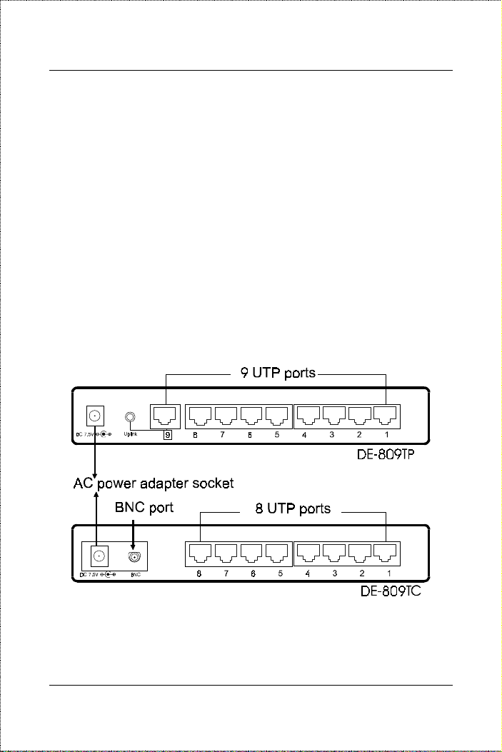
DE-809TP
♦
DE-809TC
♦
(9 UTP ports)
(8 UTP ports & 1 BNC port)
1
Port connectors on back panel of Mini Hubs
Introduction 1
Page 12

The Mini Hubs are the palm-size compact 10BASE-T hubs that
offer all the features of standard equipment rack-mount 10BASE-T
hubs, including automatic port participation, collision detection,
diagnostic LED report, and hub cascading.
Following is a summary of the features of the Mini Hubs:
9-port hubs
♦
. Each Mini Hub provides nine ports. Model DE809TP provides nine UTP ports (nine RJ-45 connectors); one of
thes e p orts can be used for either 10BASE-T con nection or
cascading with another Mini Hub. Model DE-809TC provides
eight UTP ports (eight RJ-45 connectors) and one BNC port.
Cascading
♦
. Through an “Uplink” switch, a UTP port of the
DE-809TP can be used for cascading with another Mini Hub.
The DE-809TC provides a BNC port for cascading with other
hubs without sacrificing any UTP port.
Backbone connection
♦
. The BNC port on the DE-809TC also
allows the portable Mini Hub to be attached to a coaxial
backbone t o be part of a larger network.
Installation flexibility
♦
. The Mini Hub is ideal for a small-size
network with nine or fewer nodes. Its cascading port however
permits the network to expand to 32 ports or more.
Compact, light we i g ht
♦
. The Mini Hub’s small size makes it
easy to install even at installation sites with tight space. It takes
little space on a desktop, and its light weight allows it to be
easily mounted on a wall.
2 Introduction
Page 13

10BASE-T Ethernet Mini Hubs User’s Guide
Introduction 3
Page 14

Page 15

Page 16

Page 17

10BASE-T Ethernet Mini Hubs User’s Guide
Installation
Mounting Hub on Wall
The Mini Hub can be mounted on a wall. Four mounting slots are
provided on the bottom side of the hub for this purpose. Make sure
that the front panel is exposed to allow you to view the LEDs at
work.
2
Installation 5
Page 18

Distance: 155.6 mm / 6.13 in. (top diagram)
Distance: 70.5 mm/2.74 in. (bottom diagram)
6 Installation
Page 19

10BASE-T Ethernet Mini Hubs User’s Guide
Connecting AC Power Adapter
The Mini Hub uses an external AC power adapter. There is no
power switch. The hub is powered on once the AC power adapter is
conn ected to an AC power s ource and the hub’s AC power socket.
&DXWLRQã 7R SUHYHQW GDPDJH WR \RXU KXEñ EHIRUH \RX
EHJLQ XVLQJ WKH $& SRZHU DGDSWHUñ GRXEOHð
FKHFN LWV LQSXW $& YROWDJHï 7KH $& SRZHU
DGDSWHUªV LQSXW YROWDJ H PXVW FRQIRUP WR LWV
$& SRZHU VRXUFHªV YROWDJHï $SSHQGL[ $ OLVWV
WKH VSHFLILFDWLRQV RI WKH $& SRZH U DGDSWHU V
DSSOLFDEOH WR 0LQL +XEV DQG WR GLIIHUHQW
FRXQWULHVï
,I \RX XVH DQ $& SRZHU DGDSWH U VXSSOLHG E\
\RXUVHOIñ DQG \RXU FRXQWU\ LV QRW OLVWHG LQ
WKH DSSHQGL[ñ FKHFN ZLWK \RXU QH WZRUNLQ J
SURGXFWV GHDOHU WR PDNH VXUH WKDW \RX XVH D
SURSHU $& SRZHU DGDSWHUï
Installation 7
Page 20

&DXWLRQã 8VH $& SRZHU DGDSWHU ZLWK FRUUHFW $&
YROWDJH RQO\ï
Connecting UTP Segments
This section describes the connection procedure from a UTP port of
the hub to a UTP port of a station, bridge , router, and other
Ethernet devices. It does not describe the connection to a 10BASET hub. The UTP cable extended from a UTP port is called a UTP
segment, and can be up to 100 meters long.
8 Installation
Page 21

10BASE-T Ethernet Mini Hubs User’s Guide
Note that, for Mini Hub model DE-809TP, UTP port labeled “9”
must be in the
Normal
position in order to be connectable to a
station, bridge or router. To connect this port to a UTP port of a
10BASE-T hub, the port must be in the
Uplink
position (see section
Cascading Hubs Through UTP Cable in this chapter for details).
The button to the right of the UTP port labeled “9” is used to switch
between the
Normal
and the
Uplink
position.
Installation 9
Page 22

Connecting Thin Coaxial Segment
The BNC port on Mini Hub model DE-809TC is used to connect to
a thin coaxial segment. Connect a T-connector to the BNC
conn ector, then connect bot h end s of the T-connect or to the thin
coaxial cable. If the thin coaxial segment terminates at the hub,
attach a 50-ohm terminator to one end of the T-connector.
10 Installation
Page 23

10BASE-T Ethernet Mini Hubs User’s Guide
Cascading Hubs Through Thin
Coaxial Cable
The BNC port on the Mini Hub model DE-809TC can be used to
cascade hubs together. You may cascade DE-809TC hubs together
through the BNC ports. You may also cascade the DE-809TC with
any other IEEE 802.3 Ethernet standard 10BASE-T hubs equipped
with BNC ports.
You may attach up to thirty nodes to a thin coaxial segment. In this
sense, it is possible to cascade a maximum of thirty hubs together
through the thin coaxial cable.
Be sure to leave a minimum of 0.5 meter (2 feet) of cable between
two BNC ports.
Installation 11
Page 24

Cascading Hubs Through UTP
Cable
Any of the UTP p orts can be used t o ca s cade hu bs togeth er. Note
that when two UTP ports of two hubs are connected together, the
wires inside the UTP cable must be cr ossed over. See app endix A
for the wire cross-over. Mark all crossed-over UTP cables clearly so
they will not be used by mistake for normal connection.
If you use Mini Hub model DE-809TP, UTP port labeled “9” is
especially designed for hub cascading. When this port is in the
Uplink
position, its signal reception and transmi s sion are reversed.
This allows you to dispense with the trouble of crossing the UTP
cable’s wires. Putting this port in the
by pressing down the button located next to the port.
Note: Never cause a loop when you cascade hubs since this might
cause unpredictable results.
Uplink
position can be done
12 Installation
Page 25

10BASE-T Ethernet Mini Hubs User’s Guide
Hub cascading: If straight-through UTP cable is
used, one UTP port must be in Uplink posit i on.
Installation 13
Page 26

Diagnostic LEDs & Troubleshooting
Power
♦
.
ON:
◊
◊
“power good”.
OFF:
“power bad.” Check to see if the AC power adapter
is properl y connected, or if t he correct AC power adapter i s
being used.
DE-809TP
14 Installation
Page 27

♦
10BASE-T Ethernet Mini Hubs User’s Guide
DE-809TC
Diagnostic LEDs on front panel of Mini Hubs
Collision.
Blinking:
◊
Packet collision is occurring. Packet collisions
are not an abnormal situation. Collisions occur when two
or more computers transmit packets on the network
simultaneously, and a contention takes place on the
network line. The computers should then back off, then
retry transmission. This trial-and-error process is repeated
until no collision takes place. Note: Excessive collisions
may result when multiple hubs are cascaded through a thin
coaxial segment and many stations are connected on the
network.
Off:
◊
No packet collision.
Link/Rx
♦
◊
(for each UTP port).
ON:
Data link between (1) Mini Hub’s UTP port and (2)
node’s or cascad ed hub’s UTP port is successful.
OFF:
◊
(1) No data link or (2) cable disconnected. Check
for bad ca bl e or loose connector s. For ca scaded h ubs, check
to see if UTP cable contains crossed-over wires. Also check
for a “power good” condition at both ends of the
connection. If you suspect that the hub port is damaged,
contact your authorized dealer for service.
Blinking:
◊
Installation 15
Packet recepti on is occurri ng.
Page 28

♦
♦
♦
Rx
◊
◊
Partition
◊
◊
Partition
◊
◊
(for BNC port).
Blinking:
OFF:
Packet recepti on is occurri ng.
No packet reception.
(for each UTP port).
ON:
The UTP port is being partitioned off due to excessive
packet collisions. Note that the UTP cable between a hub
port and a non-repeater node must contain straight-through
wir e s (no cross-over).
OFF:
Segment has no problem.
(for BNC port).
ON:
The BNC port is being partitioned off due to (1) no
cable is connected, (2) faulty cable or connectors, (3)
excessive packet collisions, (4) a disconnected point
somewhere along the entire thin coaxial cable length, or (5)
unterminated segment. Check all connectors along the
cable length. If segment is not terminated, terminate both
ends with 50-ohm termin a tors.
OFF:
(1) Cable is connected and (2) segment has no
problem.
Uplink
♦
ON:
◊
The “9” UTP port is in the
Uplink
position (cross-
wired).
OFF:
◊
The “9” UTP port is in the
Normal
position
(straight -t hrough wires).
16 Installation
Page 29

10BASE-T Ethernet Mini Hubs User’s Guide
Cables, Connectors &
AC Power Adapters
10BASE-T Unshielded Twisted-Pair
(UTP) Cable
♦ Cable characteristics: 0.4 - 0.6 mm (22 - 26 AWG) 8-wire
(only 4 wires used for 10BASE-T)
♦ Maximum segment length : 100 m eters
♦ Applicable connectors: RJ-45, Telco-50
A
10BASE2 Thin Coaxial Cabl e
♦ Cable characteristics: 0.2 inch diameter RG-58A/U 50 ohm
♦ Maximum segment length : 185 m eters
♦ Minimum distance between two nodes: 0.5 meter
♦ Maximum number of nodes per segment: 30
Cables, Connectors & AC Power Adapte rs 17
Page 30

AC Power Adapters
The following lists the specifications of the AC power adapters
supplied by D-Link for use with the Mini Hub. Your Mini Hub
package may contain one of these AC power adapters. If you use an
AC power adapter supplied by yourself, make sure that it complies
with the output power listed below and the input power and plug
(AC power specifications) of your area.
AC power adapter model AD-071A
⇒ Input power: AC 120 volts, 50-60Hz
⇒ Output power: DC 7.5 volts unregulated, 1 A
⇒ Maximum power consumption: 7.5 watts
⇒ Plug: North Amer i ca n stan d a rds
⇒ Safety standards: UL/CSA
AC power adapter model AD-071AD
⇒ Input power: AC 240 volts, 50-60Hz
⇒ Output power: DC 7.5 volts unregulated, 1 A
⇒ Maximum power consumption: 7.5 watts
⇒ Plug: U.K. standa rd
⇒ Safety standard: BSI
AC power adapter model AD-071AB
⇒ Input power: AC 220 volts, 50-60Hz
⇒ Output power: DC 7.5 volts unregulated, 1 A
⇒ Maximum power consumption: 7.5 watts
18 Cables, Connectors & AC Power Adapte rs
Page 31

10BASE-T Ethernet Mini Hubs User’s Guide
⇒ Plug: German standard
⇒ Safety standard: VDE
AC Power adapter model AD-071AJ
⇒ Input power: AC 100 volts, 50-60Hz
⇒ Output power: DC 7.5 volts unregulated, 1 A
⇒ Maximum power consumption: 7.5 watts
⇒ Safety standard: Japan T-mark
Cables, Connectors & AC Power Adapte rs 19
Page 32

B
Technical
Specifications
DE-809TP
♦ Standard: IEEE 802.3 10BASE-T.
♦ Medium support: UTP.
♦ Number of UTP ports: 9.
♦ Number of connectors: 9 RJ-45.
♦ Cascading: Switchable straight-through/cross-wired UTP port
(“uplink”) button
♦ Number of diagnostic LEDs: 21
♦ Power requirement: DC 7.5 volts 1 Amp.
♦ Power feeding: through AC power adapter.
♦ Operating temperature: -10° to 55° Celsius.
♦ Humidity: 5% - 95% non-condensing.
♦ Dimensions: 197 x 115 x 28 mm (7.75 x 4.53 x 1. 10 inches)
♦ Weight: 300 ±10 grams (AC power adapter excluded)
♦ Safety: UL/CSA.
♦ EMI: FCC-B, CE-B, VCCI-A, C-Tick, BCIQ
20 Technical Specifications
Page 33

10BASE-T Ethernet Mini Hubs User’s Guide
DE-809TC
♦ Standard: IEEE 802.3 10BASE-T.
♦ Medium support: thin coaxial, UTP.
♦ Number of UTP ports: 8.
♦ Number of BNC ports: 1.
♦ Number of connectors: 8 RJ-45, 1 BNC.
♦ Number of diagnostic LEDs: 20
♦ Power requirement: DC 7.5 volts 1 Amp.
♦ Power feeding: through AC power adapter.
♦ Operating temperature: -10° to 55° Celsius.
♦ Humidity: 5% - 95% non-condensing.
♦ Dimensions: 197 x 115 x 28 mm (7.75 x 4.53 x 1. 10 inches)
♦ Weight: 350 ±10 grams (AC power adapter excluded)
♦ Safety: UL/CSA.
♦ EMI: FCC-B, CE-B, VCCI-B, C-Tick, BCIQ
Technical Specifications 21
Page 34

22 Cables, Connectors & AC Power Adapte rs
Page 35

Offices
8ï6ï$ï 'ð/,1. 6<67(06ñ ,1&ï
&$1$'$ 'ð/,1. &$1$'$ñ ,1&ï
'(10$5. 'ð/,1. '(10$5.
)5$1&( 'ð/,1. )5$1&(
*(50$1< 'ð/,1. õ'(876&+/$1'ô *0%+ ,ï*ï
,7$/< 'ð/,1. ,7$/<
6:('(1 'ð/,1. $î%
8ï.ï 'ð/,1. õ(8523(ô /7'ï
LQIR#GOLQNïFRïXN
(*<37 'ð/,1. 0,''/( ($67
$8675$/,$ 'ð/,1. $8675$/,$ 37<ï/7'ï
ZZZïGOLQ NïFRPïDX (ð 0$,/ ã LQIR#GOLQ NïFRPïD X
&+,1$ 'ð/,1. %(,-,1*
,1',$ 'ð/,1. õ,1',$ô 397ï /7'ï
-$3$1 'ð/,1. 72.<2
6,1*$325( 'ð/,1. 6,1*$325( 37(ï/7'ï
7$,:$1 'ð/,1. 7$,:$1
ик 'LVFRYHU\ 'ULYHс ,UYLQHс &$ длзме 86$
7(/г мрдйдржеернени )$;г мрдйдржикржнкк :(%г ZZZпGO LQNпFRP
(р0$,/г WHFK#GOLQNпFRP
ълмен :LQVWRQ 3DUN 'ULYHс 2DNYLOOHс 2QWDULRс /з+ и:,с &DQDGD
7(/г мрднирелдринкк )$;г мрднирелдриллк :(%г ZZZпGO LQNпFD
)73г IWSпGOLQNQHWпFRP (р0$, /г VXSSRUW#GOLQNпFD (р0$,/г VDOHV#GOLQNпFD
1DYHUODQG л '.рлзнн *ORVWUXS &RSHQKDJHQс 'HQPDUN
7(/гйирйкрдздрнйн )$;гйирйкрйлйркйж
/H )/25,/(*( ълс $OOHH GH OD )UHV QH ULH
жеккн )RQWHQD\ /H )OHXU\ )UDQFH
7(/г ккрмркнлкрезее )$;г ккрмркнлкрезед :(%г ZZZпGO LQNрIUDQ FHпFRP
%DFKVWUDH ллс зиекн .ULIWHO *HUPDQ\
7(/г йдрзмдлрджммн )$;г йдрзмдлрджмммм :(%г ZZZп GOLQNпGH %%6г йд рзмдлрджммдд
,1)2г нмкнржлинрнн хWROO IUHHф +(/3г нмкнржлинрйн хWROO IUHHф
9LD 1LQR %RQQHW Qп зс лнмий 0LODQRс ,WDO\
7(/г кдрлрлдннрнзжз )$;г кдрлрлдннрмжлк
:RUOG 7UDGH &HQWHU 3п 2п %R[ жнкдзс мнж лй 6WRFNKROP 6ZHGHQ
7(/г йзрержннрзлмм )$;г йзрерлмдрзйн (р0$,/г LQIR#GOLQNпVH
'р/LQN+RXVHс з *DUODQG 5RDGс 0LGGOHVH[ +$ж м'3 8п.п
7(/г ййрмемрлкирииии )$;г ййрмемрлкириинн :(%г ZZZпGO LQNпFRP пXN (ð0$,/ã
ж $VVHP %HQ 6DEHW 6WUHHWс +HOLRSROLVс &DLURс (J\SW
7(/г лнлрлйирзмжз )$;г лнлрлйирзмдл :(%г ZZZп GOLQNрP HпFRP
8QLW мзс кдн (DVWHUQ 9DOOH\ :D\ 5RVHYLOOHс 16: лнзд $XVWUDOLD
7(/г змрлрдймжржмнн )$;г змрлрдймжрмнжж 72// )5((ã мреннмжжмн :(%ã
миWK )ORRUс 6FLHQFH ч 7HFKQRORJ\ 7RZHUс
1Rп ммс %DLVKLTLDR 5RDGс +DLGLDQ 'LVWULFWс %HLMLQJ мнннем &KLQD
7(/г езрмнрзейзжмнзрд )$;г езрмнрзейзжммн :(%г ZZZпG OLQNпFR пFQ
%RPED\ 2IILFH г 3ORW 1Rпис .XUODр%DQGUD &RPSOH[ 5Gп
2II &VW 5Gпс 6DQWDFUX] х(ф %RPED\ р йнн нде ,QGLD
7(/г дмрллрзмжлйже )$;г дмрллрзмжлйжз
мн)с ерерми 1LVKLJRWDQGDс 6KLQDJDZDрNX 7RN\R мйм -DSDQ
7(/г емркрийкйрдзже )$;г емркрийкйрдезе :(%г ZZZпGр OLQNпFR пMS
м ,QWHUQDWLRQDO %XVLQHVV 3DUNс ънкрмл 7KH 6\QHUJ\с 6LQJDSRUH знддмж
7(/ г зиржжйрзлкк )$;г зиржжйрзклл %%6г зиржжйрйжеж (р0$,/г LQIR#GOLQNпFRPпVJ
л)с 1Rп лккрл 3DRр&KLDR 5Gс +VLQр7LHQс 7DLSHLс 7DLZDQс 5п2п&п
7(/г еезрлрлдмзрмзнн )$;г еезрлрлдмйрзлдд :(%г ZZZпGO LQNпFRP пWZ
Page 36

Registrati on Car d
Print, type or use block letters.
Your name: Mr./Ms ____________________________________________________________________________
Organization: ________________________________________________Dept. ____________________________
Your title at organization:________________________________________________________________________
Telephone:_______________________________________ Fax:________________________________________
Organization's full address: ______________________________________________________________________
____________________________________________________________________________________________
Country: _____________________________________________________________________________________
Date of purchase (Month/Day/Year):_______________________________________________________________
3URGXFW 0RGHO 3URGXFW 6HULDO 1R1-3URGXFW LQVWDOOHG LQ W\SH RI
(* Applies to adapters only)
Product was purchased from:
Reseller's name: ______________________________________________________________________________
Telephone:_______________________________________ Fax:________________________________________
Reseller's full address: _________________________________________________________________________
Answers to the following questions help us to support your product:
1. Where and how will the product primarily be used?
†
Home †Office †Travel †Company Business †Home Business †Personal Use
2. How many employees work at installation site?
†
1 employee †2-9 †10-49 †50-99 †100-499 †500-999 †1000 or more
3. What network protocol(s) does your organization use ?
†
XNS/IPX †TCP/IP †DECnet †Other _____________________________
4. What network operating system(s) does your organization use ?
†
D-Link LANsmart †Novell NetWare †NetWare Lite †SCO Unix/Xenix †PC NFS †3Com 3+Open
†
Banyan Vines †DECnet Pathwork †Windows NT †Windows NTAS †Windows '95
†
Other __________________________________________
5. What network management program doe s your organization use ?
†
D-View †HP OpenView/Windows †HP OpenView/Unix †SunNet Manager †Novell NMS
†
NetView 6000 †Other ________________________________________
6. What network medium/media does your organization use ?
†
Fiber-optics †Thick coax Ethernet †Thin coax Ethernet †10BASE-T UTP/STP
†
100BASE-TX †100BASE-T4 †100VGAnyLAN †Other _________________
7. What applications are used on your network?
†
Desktop publishing †Spreadsheet †Word processing †CAD/CAM
†
Database management †Accounting †Other _____________________
8. What category best describes your company?
†
Aerospace †Engineering †Education †Finance †Hospital †Legal †Insurance/Real Estate
†
Manufacturing †Retail/Chainstore/Wholesale †VAR †System house/company
†
Government Transportation/Utilities/Communication †Other__________________
9. Would you recommend your D-Link product to a friend?
†
Yes †No †Don't know yet
_________________________________________________________________________
FRPSXWHU +H1J1/ &RPSDT 7;9,
- 3URGXFW LQVWDOOHG LQ
FRPSXWHU VHULDO 1R1
Page 37

Page 38

 Loading...