

Page 1
DJI E800
Multirotor Propulsion System
User Manual
V1.0
2015.01
Page 2

Multirotor Propulsion System
DJI E800
Disclaimer
Thank you for purchasing the E800 (hereinafter referred to as “product”). Read this disclaimer carefully
before using this product. By using this product, you hereby agree to this disclaimer and signify that
you have read it fully. Please strictly install and use this product in accordance with the manual. DJI
assumes no liability for damage(s) or injuries incurred directly or indirectly from using, installing or
retting this product improperly, including but not limited to using accessories not designated. Ensure
your ESC rmware matches the motor you will attach it to. Otherwise, you are responsible for all
consequences caused by your own conduct.
This device complies with part 15 of the FCC Rules.
DJI is the registered trademark of SZ DJI Technology Co., Ltd. (abbreviated as “DJI”). Names of
product, brand, etc., appearing in this manual are trademarks or registered trademarks of their
respective owner companies. This product and manual are copyrighted by DJI with all rights
reserved. No part of this product or manual shall be reproduced in any form without the prior written
consent or authorization of DJI.
This disclaimer is made in various language versions; in the event of divergence among different
versions, English version shall prevail.
Cautions
When powered on, the motors and propellers will rotate very quickly and may cause serious
damage and injury. Therefore, please always be aware for your safety.
1. Always y your aircraft a safe distance away from people, animals, high-voltage lines and other
obstacles.
2. Do not get close to or touch the motors or propellers when powered on, as this may cause serious
injury.
3. Make sure there is no short circuit or open circuit.
4. Check that the propellers and the motors are installed correctly and rmly before ight.
5. Check whether all parts of your aircraft are in good condition before ight. Do not y with worn or
broken parts.
6. Use compatible DJI parts.
Legend
Important Hints and Tips Reference
If you have any problems you cannot solve, please contact your local dealer or DJI customer service.
DJI Support Website:
www.dji.com/support
2015 DJI. All Rights Reserved.
©
2
Page 3
Multirotor Propulsion System
DJI E800
About
The E800 Multirotor Propulsion System is a tuned propulsion system customized for multi-rotor
aircraft weighing 3 to 5 kg. It is efcient, reliable and minimizes vibrations. A revolutionary Electronic
Speed Control (ESC) with a sinusoidal drive replaces the traditional square wave drive, and along
with the new AC permanent magnet synchronous motor, the whole propulsion system is brought
into an era of higher efficiency while providing a steady torque output. The integrated sensors
and patented algorithms give the whole system a high level of intelligence and redundancy, and
advanced features include closed loop torque control, active braking and energy optimization, real-
time system health diagnosis, distinct functional redundancy for the communication link, and more.
Furthermore, the ESC’s rmware can be upgraded by users, enabling you to enjoy the continual
development of the system. The E800 uses new quick-release propellers, which are designed
to prevent propellers from ying off during active braking. Together with the energy optimization
function of the new ESCs, propulsion performance is more efcient than ever before.
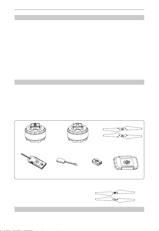
1. In the Box
Standard Package
The E800 is available in two different package congurations. The descriptions below correspond
with the Quad-rotor and Hexa-rotor packages, respectively. Please ensure that you have the correct
quantities of each part before beginning the installation process or using the product.
E.g. “1345 Quick-Release Propeller Pair ×4 or ×5” indicates that there are four pairs of propellers
included in the conguration for Quad-rotors and ve pairs of propellers included in the conguration
for Hexa-rotors.
Motor (Clockwise rotation
×
2 or ×3
ESC ×4
or
In the toolbox: Power hub, Screws (M2.5×6.3), Screws (M3×8.1), Screws (M3×5.5), Wrench for propellers, Foam
double sided adhesive tape, 2.0 mm hexagonal wrench, etc.
Optional Package
1242 Self-tightening Propeller Pair
)
Motor (Counter-clockwise rotation)
×2 or ×3
×6 Outer ESC LED Indicator ×4
1345 Self-tightening Propeller Pair
or
×6 USB Connector ×1
1345 Quick-Release Propeller Pair
×4 or ×5
Toolbox ×1
2. Gain Value Settings
The new E800 ESC, with a sinusoidal drive replacing the traditional square wave drive, offers
2015 DJI. All Rights Reserved. 3
©
Page 4

Multirotor Propulsion System
DJI E800
improved acceleration and deceleration performance. Before using, reduce the gain values
according to your ight control system and frame to achieve the same sensitivity as older ESCs (which
use a traditional square wave drive). The table below shows typical gain values when using the E800
with a DJI A2 ight control system and a frame which has a diagonal wheelbase of 580 mm:
Basic Attitude
Pitch Roll Yaw Pitch Roll Vertical
60% 60% 60% 204% 204% 100%
3. Connecting the ESCs
Tools Required
Tools: Electric soldering iron & soldering tin Use: Soldering each ESC’s power cables to the power hub
1) Check the color tags on the ESC cables to identify the default color of the ESC LED indicator (red
or green). Mount the ESCs onto the appropriate positions of your aircraft according to the LED
color. Note: The LED color can be adjusted in DJI ESC Assistant.
2) Please solder each ESC to the power pads on the power hub as shown in the gure below.
Make sure that the solder is rmly attached on the power pads and that there is no possibility for
a short circuit. The power cable is a coaxial power cable. Do not damage the protector on the
red cable to avoid short circuit.
3) Connect the signal cable to your controller. The orange wire of the signal cable is for the control
signal; the brown wire of the signal cable is for the GND; and the red wire is reserved.
4) Connect the motor to the ESC. Test the motor and make sure the rotation direction of each motor
is correct. If not, switch the position of any two cables that are connecting the motor to the ESC
to change the rotation direction.
ESC signal cable
To the controller
ESC
Power hub
Power cable
The outer power pads are for the GND cables, and the inner power pads are for the power cables.
The red core of the coaxial power cable is positive, and the shielding layer of the coaxial power
cable is negative. Make sure to solder them correctly. Try to solder the cables rmly to the power
hub at the proper length (the wire should be just long enough to reach the soldering point, without
any extra wire bunched up before the soldering point) and outward facing.
Make sure there is no short circuit or open circuit.
It is recommended that you solder a power connector onto the power hub.
4. Assembling the Propellers
Quick-Release Propellers
1) Unpack the propellers and motors.
The propellers with a CW mark should be mounted to clockwise motors, which have a black propeller
2015 DJI. All Rights Reserved.
©
4
Motor
Page 5

Multirotor Propulsion System
DJI E800
screw and a CW mark on the propel ler mount. The propellers without the CW mark should be mounted to
counter-clockwise motors , which have a silver propeller screw and a CCW mark on the propeller mount.
CW CCW
Clockwise Motor Counter- clockwise Motor
Propeller Mount
Securing Spring
2) Align the gap A inside the propeller nut with a n B on the Propeller Mount.
3) Press the propeller down onto the mount rmly and, while holding the propeller pressed down,
rotate the propeller in the lock direction
until you feel it secure in place.
4) To remove the propeller, press the propeller down rmly and, while holding the propeller pressed
down, rotate the propeller in the unlock direction
Lock: Tighten the propeller by rotating it in this direction.
Unlock: Remove the propeller by rotating it in this direction.
Active braking function is enabled by default, and is for use with the standard quick-
release propellers. Using this function with self-tightening propellers may cause the
propellers to y off or other ight problems.
Be sure to press the propellers down rmly until they are all the way down before rotating
to attach or detach them from the motors. Otherwise the propeller or propeller mounts
may be damaged.
When attaching a new propeller for the rst time, it may not secure in place properly after
rotating, because the hole on the propeller nut is blocked. In this case, pull the propeller
up to help lock it in position. Then hold the motor in place and try to rotate the propeller.
If it can’t be loosened without pressing down, it is locked in place.
When storing for an extended period, remove the quick-release propellers to prevent
undue wear on the spring locks.
Active braking:
and the rotational energy will be recovered.
The motor will provide reverse torque actively to slow down the propeller,
until it can be removed easily.
Attaching the
propeller
2015 DJI. All Rights Reserved. 5
©
Page 6

Multirotor Propulsion System
6 × M3-6H
Thread depth
3 mm
4 × M3-6H Thread depth 4 mm
DJI E800
Self-tightening Propellers (Optional)
1) Select “Self-tightening propeller” in the DJI ESC Assistant. (Refer to 7. Updating your ESCs
Page 7 for details)
2) Remove the two screws (M3) on the top of the motor. Then remove the propeller mount and
securing spring.
3) Attach the propeller with a silver nut onto the counter-clockwise motor (which has a silver
propeller screw). Attach the propeller with a black nut onto the clockwise motor (which has a
black propeller screw).
4) Tighten the propeller by rotating it in the lock direction
5) Remove the propeller by rotating it in the unlock direction
.
.
“Quick-release propeller” is set by default. When changing the type of the propeller, be
sure to select the corresponding type in the DJI ESC Assistant.
DO NOT use any thread locker on the propeller or motor threads.
5. Mounting the Motors
Mount each motor to a frame arm according to the size of the assembly hole.
16 mm
25 mm
19 mm
Assembly hole on the bottom of the motor
Assembly hole on the top of the motor without
the propeller mount and securing spring
12 mm
The screw size is M3. Mount the motors using appropriate screws.
Note the thread depth and the size of the screws. Using screws that are too long or too
large may damage the motor.
6. ESC Ports Description
There are two ports on every ESC. They are Data/ESC Firmware Update Port and Outer ESC
LED Port. Identify the marks on the ESC.
2015 DJI. All Rights Reserved.
©
6
13 mm
Page 7

Multirotor Propulsion System
DJI E800
Ensure your ESC rmware matches the motor you will attach it to. Refer to the tag on back
of the ESC to see the default rmware version.
Mount the outer ESC LED indicators according to your needs.
The Data/ESC Firmware Update Port is used to update the ESC rmware
and adjust the ESC. To do this, visit the ofcial DJI website to download
the DJI ESC Assistant.
http://www.dji.com/product/e800/download
7. Updating Your ESCs
ESC USB Connector PC
Unplug any other serial devices connected to your PC before updating. Then follow the instructions below:
1) Download the ESC Assistant installer from the DJI website. Run the installer and follow the
prompts to nish the installation.
2) Connect one end of the USB Connector to the Data/ESC Firmware Update Port. Connect the
other end of the USB Connector to a PC with a Micro-USB cable. Power on the ESC. DO NOT
disconnect until conguration is nished.
3) Run the ESC Assistant and wait for the ESC to connect. Watch the indicators on the bottom of
the screen. When connected successfully, the Computer Connection status will be solid green
and Data Exchange Indicator will blink blue.
4) Click on the [View] page. In the “ESC” section, check the current rmware version and ensure
the installed rmware is the latest version. If not, click the link and follow the prompts to upgrade.
5) The color of the ESC LED indicators, the type of propeller, etc. can also be adjusted through the
DJI ESC Assistant.
The DJI ESC Assistant supports Windows XP, Windows 7 and Windows 8 (32 or 64 bit).
8. ESC LED Indicators & Sound Description
The description is the same for both outer ESC LED indicators and inner ESC LED indicators, as
shown below:
LED Indicators Sound Description
Yellow, Green blinking in turn
/
Red or Green blinking slowly
— / —
Solid Red or Green
None Motor is being recognized.
1356 Ready.
None Motor starts normally.
2015 DJI. All Rights Reserved. 7
©
Page 8

Multirotor Propulsion System
DJI E800
None Fail to Self-Test.
Red, Yellow blinking in turn
Quick Yellow blinking BBBBBB…
Slow Yellow blinking
Quick Red blinking None Error, land your aircraft immediately*
* You can learn more about any errors by connecting the ESC to the DJI ESC Assistant.
You can understand the working status by observing the LEDs and listening to the sound
of the ESC.
BB---BB---BB---BB… Input voltage is abnormal.
BBB----BBB----BBB…
B--------B--------B… No signal input.
The motor parameters don’t match the
rmware data saved in the ESC.
Throttle stick is not at the bottom position.
9. Specications
Max Thrust 2100 g/rotor @ 25 V Sea Level
Takeoff Weight Recommended 800 g/rotor
Battery Recommended 6 S LiPo
Working Temperature -5°C ~ 40°C
ESC
Max Allowable Voltage 26 V
Max Allowable Current (Persistent) 20 A
Signal Frequency 30 Hz ~ 450 Hz
Battery 3 S ~ 6 S LiPo
Motor
Stator Size 35×10 mm
KV 350 rpm/V
Weight 106 g
Propeller
Diameter / Thread Pitch
1345 Propellers: 13×4.5 inch
1242 Propellers: 12×4.2 inch
2015 DJI. All Rights Reserved.
©
8
Page 9

The content is subject to change.
Download the latest version from
http://www.dji.com/product/e800
If you have any questions about this document, please contact DJI
by sending a message to
2015 DJI. All Rights Reserved.
©
DocSupport@dji.com
.
 Loading...