

Page 1
A
f
Description
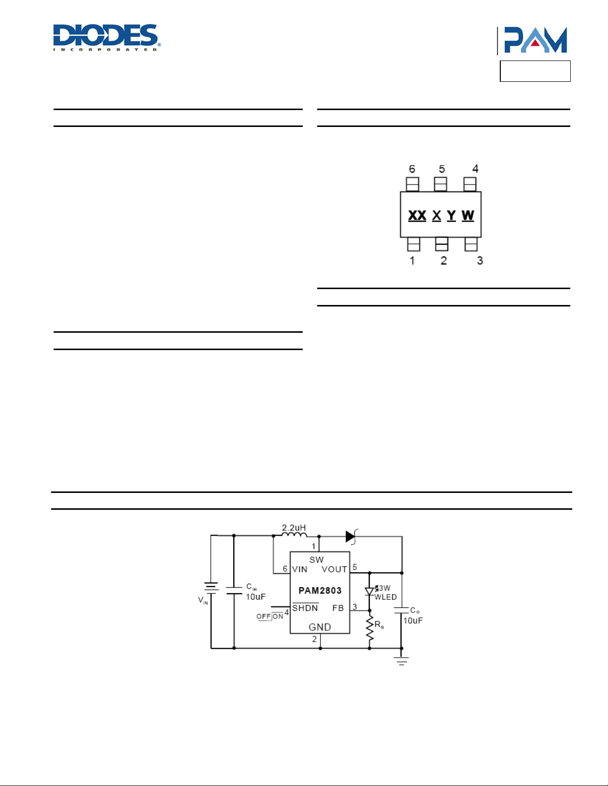
The PAM2803 is a set-up DC-DC converter that delivers a regulated
output current. The device switches at a 1.0MHz constant frequency,
allowing for the use of small value external inductor and ceramic
capacitors.
The PAM2803 is targeted to be used for driving loads up to 1A from a
two-cell alkaline battery. The LED current can be programmed by the
external current sense resistor, R
pin (FB) and ground. A low 95mV feedback voltage reduces the
power loss in the Rs for better efficiency. With its internal 2A, 100m
NMOS switch, the device can provide high efficiency even at heavy
load. During the shutdown mode, the feedback resistor R
load are completely disconnected and the current consumption is
reduced to less than 1µA.
The PAM2803 is available in the 6-lead TSOT26 package.
, connected between the feedback
S
and the
S
Features
LED Power Efficiency: up to 90%
Current Accuracy: 5%(V
Low Start-Up Voltage: 0.9V (I
Low Hold Voltage: 0.75 (I
1MHz Switching Frequency
Uses Small, Low Profile External Components
Low R
Over Temperature Protection
Low Profile TSOT26 Package
Pb-Free Package
: 100m (typ)
DS(ON)
= 3.6V to 1.8V @VF = 3.7V)
IN
= 270mA)
LED
= 200mA)
LED
Typical Applications Circuit
Product Line o
Diodes Incorporated
3W HIGH POWER WHITE LED DRIVER
Pin Assignments
Top View
TSOT26
Applications
White LED Torch (Flashlight)
White LED Camera Flash
DSC(Digital Still Camera)Flash
Cellular Camera Phone Flash
PDA Camera Flash
Camcorder Torch(Flashlight) Lamp
PAM2803
= 750mA, RS = 0.127Ω
I
LED
PAM2803
Document number: DSxxxxx Rev. 1 - 1
www.diodes.com
1 of 9
July 2013
© Diodes Incorporated
Page 2
A
f
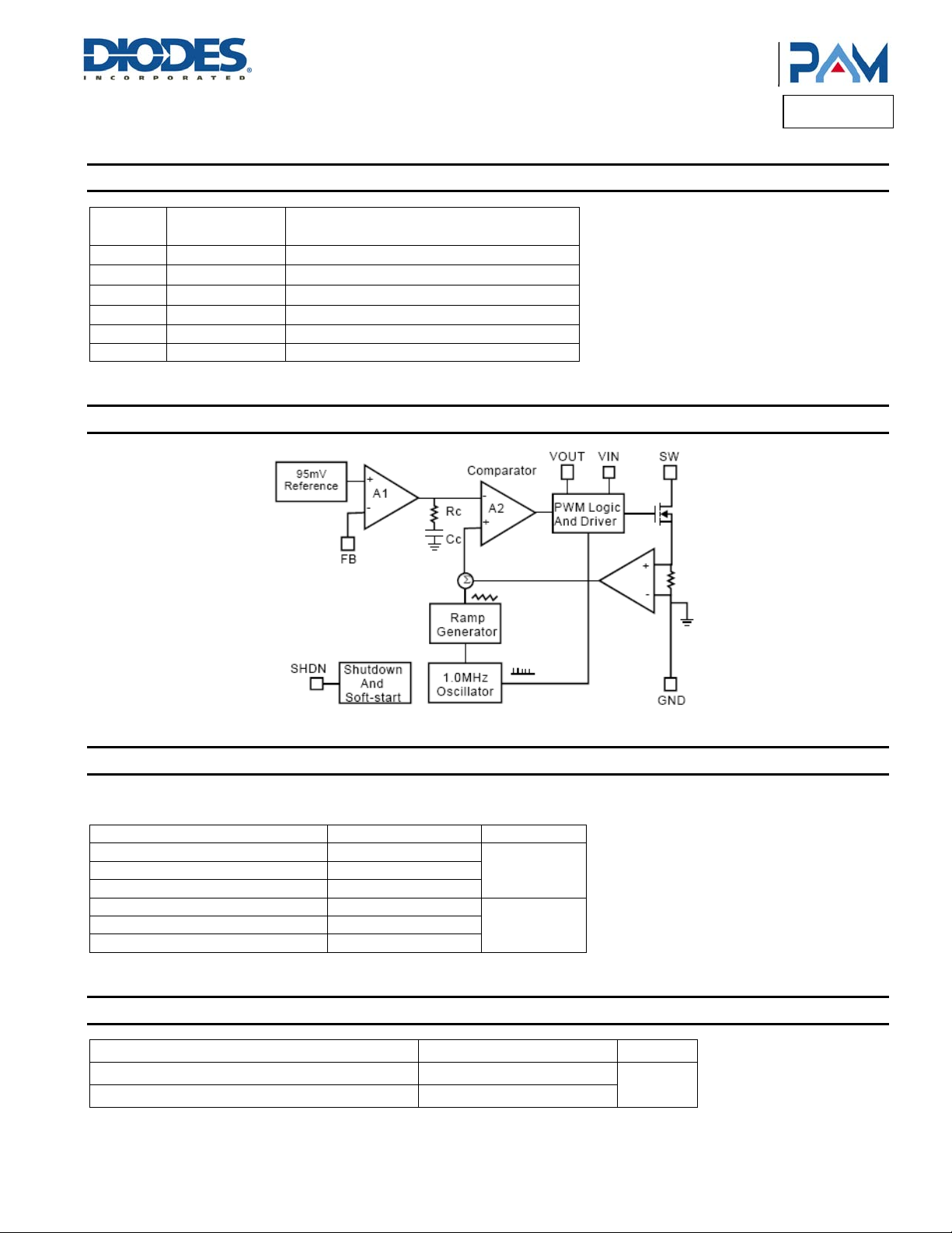
Pin Description
Pin
Number
1
2
3
4
5 VOUT Output
6 VIN Input
Pin
Name
SW Switch
GND Ground
FB Feedback
SHDN Shut Down
Block Diagram
Product Line o
Diodes Incorporated
PAM2803
Function
Absolute Maximum Ratings (@T
These are stress ratings only and functional operation is not implied. Exposure to absolute maximum ratings for prolonged time periods may
affect device reliability. All voltages are with respect to ground.
Parameter Rating Unit
Input Pin Voltage -0.3 to +6
SW Pin Voltage -0.3 to +6
SHDN, FB Pin Voltage -0.3 to +6
Operating Temperature Range -40 to +85
Storage Temperature Range -65 to +125
Lead Temperature (Soldering, 5 sec) 300
Recommended Operating Conditions (@T
Parameter Rating Unit
Junction Temperature -40 to +125
Ambient Temperature -40 to +85
PAM2803
Document number: DSxxxxx Rev. 1 - 1
= +25°C, unless otherwise specified.)
A
V
°C
= +25°C, unless otherwise specified.)
A
2 of 9
www.diodes.com
°C
July 2013
© Diodes Incorporated
Page 3
A
f
Product Line o
Diodes Incorporated
PAM2803
Thermal Information
Parameter Symbol Package Max Unit
Thermal Resistance (Junction to Case)
Thermal Resistance (Junction to Ambient)
Internal Power Dissipation
JC
JA
P
D
TSOT26 130
TSOT26 250
°C/W
TSOT26 400 mW
Electrical Characteristics
(@TA = +25°C, VIN = 2.4V, I
Parameter Symbol Test Conditions Min Typ Max Units
Input Voltage Range
Feedback Voltage
Start-Up Voltage
Hold Voltage
Oscillator Frequency
SHDN Input High
SHDN Input Low
Over Temperature Shutdown OTS 150 °C
Over Temperature Hysteresis OTH 15 °C
Maximum Output Current Range
Quiescent Current
Shutdown Current
Switch On Resistance
Current Limit
Efficiency
Note: 1. VF – LED forward voltage.
PAM2803
Document number: DSxxxxx Rev. 1 - 1
= 750mA, V
LED
= VIN, L = 2.2µH, CIN = 10µF, CO = 10µF, unless otherwise specified.)
SHDN
V
IN
V
FB
V
VIN: 0V – 3V, I
START
VIN: 3V – 0V, I
V
HOLD
F
OSC
VIN = 1.8V
V
SH
V
VIN = 1.8V
SL
I
O(MAX)
I
Q
I
SD
VO = 3.4V
R
DS(ON)
VO = 3.4V
I
LIM
0.9
-0.2
V
F
(Note 1)
V
90 95 100 mV
= 370mA
LED
: 750mA – 200mA
LED
0.9 V
0.75 V
0.85 1.0 1.15 MHz
1.0 V
0.4 V
750 mA
= 0mA, VO = 3.4V,
I
LED
Device Switching @ 1MHz
1 3 mA
Shutdown Mode 1 µA
0.1
2 A
= 750mA
I
LED
3 of 9
www.diodes.com
90 %
July 2013
© Diodes Incorporated
Page 4

A
f
Typical Performance Characteristics (@T
Product Line o
Diodes Incorporated
PAM2803
= +25°C, L = 2.2µF, CIN = 10µF, CO = 10µF, unless otherwise specified.)
A
PAM2803
Document number: DSxxxxx Rev. 1 - 1
www.diodes.com
4 of 9
July 2013
© Diodes Incorporated
Page 5
A
f
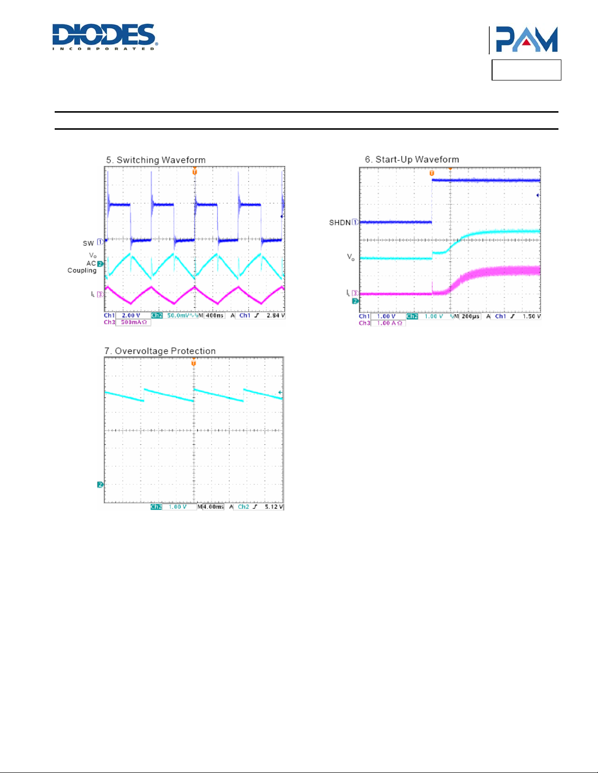
Typical Performance Characteristics (cont.) @T
Product Line o
Diodes Incorporated
PAM2803
= +25°C, L = 2.2µF, CIN = 10µF, CO = 10µF, unless otherwise specified.)
A
PAM2803
Document number: DSxxxxx Rev. 1 - 1
5 of 9
www.diodes.com
© Diodes Incorporated
July 2013
Page 6

A
f
Product Line o
Diodes Incorporated
PAM2803
Application Information
Inductor Selection
The PAM2803 can use small value inductors due to its switching frequency of 1MHz. The value of inductor will focus in the range of 2.2µH to
4.7µH for most PAM2803 applications. In typical high current white LED applications, it is recommended to use a 4.7µH inductor. The inductor
should have low DCR (DC resistance) to minimize the I
without saturating.
Capacitor Selection
An input capacitor is required to reduce the input ripple and noise for proper operation of the PAM 2803. For good input decoupling, Low ESR
(equivalent series resistance) capacitors should be used at the input. At least 2.2µF input capacitor is recommended for most applications.
A minimum output capacitor value of 6.8µF is recommended under normal operating conditions, while a 10µF-22µ F capacitor may be required
for higher power LED current. A reasonable value of the output capaci tor depends on the LED current. The ESR of the output capacitor is the
important parameter to determine the output voltage ripple of the converter, so low ESR capacitors should be used at the output to reduce the
output voltage ripple. The small size of ceramic capacitors is an excellent choice for PAM2803 applications. The X5R and X7R types are
preferred because they maintain capacitance over wide voltage and temperature ranges.
Diode Selection
It's indispensable to use a Schottky diode rated at 2A with the PAM2803. Using a Schottky diode with a lower forward voltage drop is better to
improve the power LED efficiency, and its voltage rating should be greater than the output voltage. In application, the ON Semi conductor
MBRA210LT3G is recommended.
LED Current Setting
The LED current is set by the single external RS resistor connected to the FB pin as shown in the typical application circuit on Page 1. The typical
FB reference is internally regulated to 95mV. The LED current is 95mV/R
better LED current accuracy. The formula and table 1 for R
Table 1. R
Standard Value (Ω)
R
Resistor Value Selection
S
0.18 528
0.15 633
0.12 792
0.10 950
/mV95
I
LEDS
(mA)
I
LED
PCB Layout Guidelines
As for all switching power supplies, the layout and components placement of the PAM2803 is an important step in the design; especially at high
peak currents and high switching frequencies.
The input capacitor and output capacitor should be placed respectively as close as possible to the input pin and output pin of the IC; the inductor
and schottky diode should be placed as close as possible to the switch pin by using wide and short traces for the main current path; the current
sense resistor should be placed as close as possible between the ground pin and feedback pin.
PAM2803
Document number: DSxxxxx Rev. 1 - 1
2
R power loss, and it requires a current rating of 2A to handle the peak inducto r current
. It's recommended to use a 1% or better precision resistor for the
S
selection are shown as follows:
S
6 of 9
www.diodes.com
July 2013
© Diodes Incorporated
Page 7

A
f
Ordering Information
Product Line o
Diodes Incorporated
PAM2803
Part Number Marking Package Type Standard Package
PAM2803AAF095
Refer to Marking
Information Below
TSOT26 3000 Units/Tape&Reel
Marking Information
Top View
TSOT26
PAM2803
Document number: DSxxxxx Rev. 1 - 1
7 of 9
www.diodes.com
© Diodes Incorporated
July 2013
Page 8

A
f
Package Outline Dimensions (All dimensions in mm.)
TSOT26
Product Line o
Diodes Incorporated
PAM2803
PAM2803
Document number: DSxxxxx Rev. 1 - 1
www.diodes.com
8 of 9
© Diodes Incorporated
July 2013
Page 9

A
f
Product Line o
Diodes Incorporated
PAM2803
DIODES INCORPORATED MAKES NO WARRANTY OF ANY KIND, EXPRESS OR IMPLIED, WITH REGARDS TO THIS DOCUMENT,
INCLUDING, BUT NOT LIMITED TO, THE IMPLIED WARRANTIES OF MERCHANTABILITY AND FITNESS FOR A PARTICULAR PURPOSE
(AND THEIR EQUIVALENTS UNDER THE LAWS OF ANY JURISDICTION).
Diodes Incorporated and its subsidiaries reserve the right to make modifications, enhancements, improvements, corrections or other changes
without further notice to this document and any product described herein. Diodes Incorporated does not assume any liability arising out of the
application or use of this document or any product described herein; neither does Diodes Incorporated convey any license under its patent or
trademark rights, nor the rights of others. Any Customer or user of this document or products described herein in such applications shall assume
all risks of such use and will agree to hold Diodes Incorporated and all the companies whose products are represented on Diodes Incorporated
website, harmless against all damages.
Diodes Incorporated does not warrant or accept any liability whatsoever in respect of any products purchased through unauthorized sales
channel.
Should Customers purchase or use Diodes Incorporated products for any unintended or unauthorized application, Customers shall indemnify and
hold Diodes Incorporated and its representatives harmless against all claims, damages, expenses, and attorney fees arising out of, directly or
indirectly, any claim of personal injury or death associated with such unintended or unauthorized application.
Products described herein may be covered by one or more United States, international or fo reign p atents pending. Product names a nd markings
noted herein may also be covered by one or more United States, international or foreign trademarks.
This document is written in English but may be translated into multiple languages for reference. Only the English version of this document is the
final and determinative format released by Diodes Incorporated.
Diodes Incorporated products are specifically not authorized for use as critical components in life support devices or systems without the express
written approval of the Chief Executive Officer of Diodes Incorporated. As used herein:
A. Life support devices or systems are devices or systems which:
1. are intended to implant into the body, or
2. support or sustain life and whose failure to perform when properly used in accordance with instructions for use provided in the
labeling can be reasonably expected to result in significant injury to the user.
B. A critical component is any component in a life support device or system whose failure to perform can be reasonably expected to cause the
failure of the life support device or to affect its safety or effectiveness.
Customers represent that they have all necessary expertise in the safety and regulatory ramifications of their life support devices or systems, and
acknowledge and agree that they are solely responsible for all legal, regulatory and safety-related requirements concerning their products and
any use of Diodes Incorporated products in such safety-critical, life support devices or systems, notwithstanding any devices- or systems-related
information or support that may be provided by Diodes Incorporated. Further, Customers must fully indemnify Diodes Incorporated and its
representatives against any damages arising out of the use of Diodes Incorporated products in such safety-critical, life support devices or
systems.
Copyright © 2013, Diodes Incorporated
www.diodes.com
IMPORTANT NOTICE
LIFE SUPPORT
PAM2803
Document number: DSxxxxx Rev. 1 - 1
9 of 9
www.diodes.com
July 2013
© Diodes Incorporated
 Loading...