

Page 1

I'InITECH
ii::iiiiiiii
K
3
-CH
PCM
Radio
Control System
Instruction Manual
Thank
you
for
purchasing
our R/C system.
Before using. read this manual carefully.
2.1G
DIGITAL
PROPORTIONAL R/C SYSTEMII
I I
Page 2

/./
?
Caution
To work
your
R/C with
your
models
correctly
and
safcly, rcad this
manual
carefully and keep it in
a safe
way as a
rcfcrcnce introtiuction
in thc futurc.
Warr-ring:
1. This
product
is only
equipped
for radio
controlled rnodels;
2.
The
usage of
this product
should
be approved
by
local relevant
law or
regulations;
3. We will
not be
responsible
for
the
damages causcd by unauthorized
modification,
adjushnent
or
replaccmcnt
ofparts ofthis
ploduct;
4. The
manual may be altered without plior
noticc. Plcase
contact us
if you
have
any corrections
or claritlcations that should
be made in
the
rranual.
Please
pay
more
attention to the
parts
in this manual, which
are
ntarked
n,ith
"Waming".
Becartse
of
disturbancc,
do not work
youl
tadio control
system
sinrultancously
with
othcrs at the same
frequency.
Before
starling the transmitter, make
sure
the transmittcr
battcrics
are well
loaded .The
voltage of transmitter
battcrics is ncvcr lower
than 8.6V Ancl
please
check and
confirm
that
the selvos are all
well and
propelly
connected.
Please
check and have
a test on control
surfaces to
confirm
the
transrnitter
handling
of each
part prior
to each takeoff. The flecluencies
of thc
module and
the receiver
should
be the
same.
Keep the
radio system
away from moist,
high temperature
and strong
shake.
Do
not clean
the
product
witb
solvent.
The antenna does not touch
anything
else
when power
srvitch is tunred
on. Do
not leave
this
product
and its accessories
within the reach
of small children.
Please
use
this
product
according to
your
local relevant
law
or
regulation,
we
are
not responsible for
any incidents or
damages.
LCD
Power Switch
Charging Jack
Edit Buttons
Edit Buttons
MODE&DATA
+
MODE&DATA
_
A'.
@
ENTER
V
\..
ENTIiR
EX
IT
YoDE&DArA
o
wt
1.1 Basic
Introduction
DC-1500is a 3 cliannel
pistol
grip
radio
controller. C'hannel l:steerin_c,
Channel
l:throtlle.
Channel 3
:AUX.
DCI-l500supports
PCM.2.4G
and FM. FM
and
2.4G can
not be replaced, for it is scr
up by manufacturer
in the production
process
and the
system can
examine
it
autornatically,
and
LCD
displays
thc different
instruction.
DC-l500will
start the initial
inspcction
of the system
when
it is switchcd
on. it
takes
onl)
I .1
iccorrds
for thc inspection.
1.2 DC-f
500 Chart
Antenna
AUX
Channel
Steering
Trim
Steering
Wheel
Throttle
Trim
Throttle
Trigger
Throttle
Hold
Steering
Dual
Rate
Battery
Box
R/C lnstruction
lvlanual
R/C Instruction
l\y'anual
Page 3

2.I MENU FUNCTION
Modulation
2.2 Characteristics
of
system
--SP[l]r)
TII-SPIIED:
Sudden
trigger
opcration on a
slippery
road
surf'ace
will only cause
the tires to spin and the model
to not accelerate
smoothly.
By
setting
the throttlc spccd
finction. operation
can be
performed
srnoothly and easily.
It
also suppresses
battcry
consumptlon.
ST-SPEED. When
you
scnse that
the steering servo is too fast, etc.,
the
servo
operating speed
(direction
that suppresses the maximurn
speed) can be adjusted.
--Auto-Start
function
(ATS):
A
pre-set
throttle
position, less
than
full throttle, to
be used fbr the initial
accelcration off the line without having wheel
spin.
When the
trigger is released, auto-start
is turned ofTand throttle operates normally again.
--Racing
timer
(TIMER)
DC
-1500
hastwo timers:Down_Timerand
UP Timer.
- -Digital
trim f
unction
The current trirn
position
is
displayed on the LCD scrccn.
2,3 EPA
Voltage
Model Name
Timer
Steering
Tri
El
10.2v,
D/R:
M00:mod00
i
7
0
T*I:00:q0
1Htn:
ST.
+
f]l.r
r
rl r r r
Function 10.2V
-..':
6:TH CURV
Z:ABS
8:MODEL
Steering
Dual Rate
Throttle Hold
Function 10.2V
Function
10.2V
.'::: . : ai:::l:t
i
-:r
: i. . . :rlillll:i:,
:llll.
t.n /p
3:S_TRIM
t1
.Dtr\l
E PA IO.2V
r
1!0x
120%1007,
B
1007,1207,1007,
E PA 10.2V
ST
THAU)
F
::.(
t20%
ao%
B
1007,.12071AO7
i
Throttle Tri
--3
channels End Point Adjustment
--Support
dual
rate f-unction fbr the STEERING
--Sub-trim
tbr THROTTLE channel
and STEERING
channe I
--Model
namcs can usc up to 5 letters
and nunrbers,
so that casily undcrstood namcs
can be set. A
modcl mcmory with ditl'erent
l'ine
setups can be created b1, using the motlcl
copy function.
Sixtccn modcls can bc adclcd .
--Brakc
mixing lbr largc
cars
(llRAKIr)
Brake miring
of'the front
and
rear u,hcels
of l/5GP
and othcr
large
cars
can
adjustcd independcntly.
--Anti-skid
braking system
(A.B.S)
This
f'unction
applies the brakes so that thc
tires ofgasolinc
engine
cars, etc.
(lo
rlol
lose their grip
on the road
cvcn whcn brakin-q
at corncrs
l'Use
this when performing
left and right stccring
anglc adjustmcnts, throttle high side/brake side
operation amount adjustment, and channel 3 servo
up sidc/down side operation amount adjustment
during linkagc.
l"
Bpl, adjusting value range:
0-120 %, def
ault is
I 00%
l.Press
"ENTER"
in thc
power
on intcrfacc and
enter
function
mcnu. Prcss
"+"
or
"-"
to choosc
"EPA".
And
press
"ENTER"
and enter
E&\
adj usting
interface.
2.Press
"ENTER"
to choose cach adjusting
item,
and then
press "+"
to increase
and
"-"
to decrease
the value ofthe
corresponding
item.
-l.Press
"EXIT"
to save
your
setting and leave
!ft\
interface. and back
to the function
mcnu intcrf-acc.
TERMS:
F-FORWARD,B-BACK,ST-STEERIN,
TH-THROTTLE.AUX-AUXILLIARY
LEFT
BACK
RIGHT
FWD
2:D/R
3:S_TRIM
4:REV
Function 10.2V
I4:TH
HOLD
l5:F/S
l6:NEUTRAL
Function
10.2V
:&*X*i.;i::
18:RESET
l9:M_RES
20:TIMER
R/C lnstruction
Manual
R/C
Instruction
l\.4anual
sF_R_v!
]
Page 4

2.4
DtR
ST D/R 10.2V
PoS0:f&%
Pos I :J00
%
--DlR
is used to change the action range
o1'steeline
servo when turning the
steering wheel.
Increasing
DiR
will make the stccring wh{rcl
action more sensitive.
--DlR
adjusting
value range: 0- 1200.1o,
POS0
delault value
is 100%,POS
I default valuc is 70%.
--Press
the ST.D/R dial to select POS0 or
POS I , and
the value willdisplay in the LCD when it is on
the main
sc reen.
l Press
"ENTER"
to
see
FUNCTION MENU.
2. Press
"+"
or
"-"
to choose
EB.
and
pr
ess
"ENTER"
to enter D/R adjusting interf'ace.
3.Press
"*"
to increase
and
"-"
to decrease
pl(
value.
4.Press
"EXIT"to
save
your
setting
and
leavc
EIR
interface, and back to
the function
menu interf-ace.
TERMS: POS-POSITION
2.5 S TRIM
S-TRIM 10.2V
ST:
W
TH:
til
I
120o/o
LEFT
RIGHT
BACK
FWD
I
Senyg
l
REVERSE
10.2V
!!
TH
AUX
REVf
NOR
I
'$T
Function
10.2V
6:TH CURV
7:ABS
8:MODEL
ST EXP 10.2V
M:EXP
D.A
o?
f\.v /o
ST-EXP IO.2V
.M:EXP
R:50
%
2.6
REV
This firrrction
rc\
L-rscs the direction ol opcration
of
lhc
sr-rvos rclatcd
to
transnrittcr sleering, throttlL-.
ilnd
chunnel -l
opcratiou.
l.Press
"ENTER"
to see FUNCTION
N,lENU.
2.Press
"i"
or
"-"
to choose RIIVERSF.,
and
press
"ENTER"
ro
enrcr
REVERSE adjustrng
intcrface.
LPress
"EN'f
ER"
to choose each
Channcl.
:l.Prcss
"t"
1o increasc
and
"-"
to
choosc
"REV"
or
"NOR".
5.1)rcss
"[:XIT"tr)
sa\ c
y()ur
sellinq
and leave REVIlRSE
interf'ace, and
back
trr
thc
Iirrtctrorr
nrcnu
intcrtace.
Notc:
However, when the
position
set by trim
or
sub trim shifts from
the
center,
the
center
becomes the
opposite
side.
Tl:R\4S:
ST-STEERINC;.
TH-THROTTLE.AIJX-AUXI
LLIARY
2.7
ST-CURV
l00o/o
--Use
this function to adjust the
neutral
position
of
the steering
and
throttle servos.
--SUB
TRIM adjusting valuc
range:
-100-100
Default
is
0
l.Press
"ENTER"
to see FUNCTION
MENU.
2.Press
"+"
or
"-"
to choose TRIM,
and
press
"ENTER"
to enter SUB
TRIM adjusting
interface.
J.Press
"+"
to increase
and
"-"
to dccrease
SLIB
TRIM
valuc.
4.Press
"EXIT"to
save
your
setting
and
leave
SUB
TRIM
intertace,
and back
to
the
function
menu intert'ace.
TERMS: ST.STEERING,
TH-THROTTLE
I
his lirnetiort
is ttsctl to chrngc
lhe scnsitir
itv oftlrc-
stccring sc.rvo arountl
the neutlal
|1()\itiorr
It has no
ctlect on the
rrraxirilunt
scrv0 trarcl.
Notc:
When the setting is
not determined, or the
characteristics
of the
model are
unknown,
start lvith 0Yo
(
n hen EXP is
set to 07o,servo
movement is linear)
LPrcss
"F\T[:]R"
to sce Ft.rNC''f
I()N \{ENU
l.trsc
thc
|
-
Kc)s to selecr
thc
STC'URV tilnction
antl
press
ENl'LR.
.l.Llsc
tl,t'
-'-
Kcl to chrngr'tlte valuc.
:lI'rcssl:\lTtosltcatttl
rL'lur'nl()lrUNa'TIONMItNLl.rrlcssEXITa{aintgt'!'lgrrlro
tl)r'\1f,iil
Se tce n.
S'f
Ill;RI\(;
(
t-il{\'llR ad
justinu
raluc rangc:
-
100'}i,
,+1009.1,
Stecling
[.)XP ad.j ustment
L\\/hcrr
Iou
$rnt to c[rickcn
stcc|ing 0pcrati0n.
use thc
(]
sriie \\'ircrr
.,oit
\\ant to rrakc
steering opclation
nrildcr,
use
the
5t(la.
I)cfault is 0'/o(
Lincar)
)
button to
ad.just
thc
+
(-)
button t0
ad.iust the
-
I \!
lrtn crrtling
sctting,
rctllnt
to tlte I'ullction nte
nu by
pressing
thc
(EXl'l
)
button
l
l:lt\lS; \l-\l()DE. l{--ltAl'E
Function
10.2V
3:S_TRIM
4:REV
R/C lnstructron
Manual
R/C
Instruction l\,4anual
Page 5

2.8 TH-CURV
TH CURVTHROTTLECURVES
This firnction makes
thc throttle
high
sidc and
brake sidc direction servo opcratitrn
quickcr
or nrilder. It has
no cftect on
the
scrvo maxinrum
opcration amount.
For the high
side, sclcction li'om among
three
kinds
of curve s
(EXPTVTR/Clt-lR)
is also
possiLrle
.
Note: When
the course conditions are
good
and
there
is no
sense oftorque at the
power
unit, set each curve to the
+
side
(quick
side).
When
the
road
surfrce
is
slippery
and
the drive
wheels
do not
grip
it, set each
curve
to the
-
minus
(mild)
side.
Note: Brakc
side only has EXP curves.
1 Press
"ENTER"
to
see
FUNCTION
MIINU
2 Use the
+/-
Keys to
select
theTH
CURV
function
andpress ENTER.
J Prcss F.NTER to sclcct
c selling.
4 Usc thc
+/-
Key to
change the
valuc.
-5 Press
EXIT
to
save and rcturn
to
FUNCTION iVIEi''U,
press
EXIT again
Io
relufll ro
the Main Scrcen.
H
CURV IO.2
M:CUR
I
:
| 2
31,
,
R:25
I
I
B
R:0
CURV IO.2
M:CUR
] :
l:gi
3l
I
R:20
|
B R:0
Adjustment
method
for
VTR curve
--Select
VTR at
setup itern
"M"
--Sclcct
sctup itcnr
"R"
and make
the fir)lorving
adusrments:
I . Forward
sidc
adjustment:
Usc
thc
(+)
buttor.r
to adjust the
+
side when you
s'ant to
quicken
the rise
ancl use the(-)
buttor.l
to adjust the
side when
you
want to rnake
the rise miltler.
2.Curve
swilching
point
odiustmeni:
When
you
wont to
chonge
the curve
switching
point
relotive
to the
ihroflle
trigger,
select
the setting
item
"P"
by ENTER
button, ond
use the
(+)
ond
(
)
buttons to
move to the
point
Vou
wont to set.
3.When
ending
setting,
return
to thc initial
scrccn by
prcssing
the EXIT
TH CURV 10.2
M:EXP
43
B R:0
H CURV IO.2V
M:EXP
R:
-32
BR:-80
CURV IO.2
M:VRT
I
:
1: 50
R:
50
BR:
0 li
TH
CURV 10.2\
M:VRT
P:
50
F: 25
BR:
O
TH
CURV
IO.2\,
M:VRT
P: 80
R:25
i*t{S:45
Quick
lbrward(R:0- lt)())
Milcl
lorward{R: 100-O) Mild
backrvard{BR:
100-0)
Adjustment
method for E,XP curve
--Sclect
EXP at sctup itcnr
"M"
--Sclect
setup itcm
"l{"
and makc
the
lbllowirrg ad.jr.lstmcnts;
I .Forwarcl
side
adjuslment:
Use
thc
1+1button
to
ad-1ust
thc
+
sidr-
whcn
yoLl
\\ant
to
quick!-n
thc risc rnd
rrsc
thc(-
)
Lrutton to
ad.iust
the - sidc * hen voLr
\\
olrt lo nlrkc
lhc
lisc nrrldcr.
2.Broke
side odjustmenl:
Select
the setting item
"BR"
by
ENTER bution
ond
use the
(+)
buttcn
fc
odjust ihe
+
side
when
you
wont to
quicker
the
rise
oncl use
the
(.)
bution
1c
odjust the
side
when
you
wont
to
moke ihe
rise milder.
-l.Whcrt
cnding
sclf inr.
relunr 1{)
thr'inilial scle
or I.r
prcssinu
thc IrXl
l
rorward sr(le
Forward
stde
euick
backward(BR:O- l0O)
Adjustnrcnt
mctliod
lbr CLIR
curvc
--Se
le ct CUR at
sctup itcm
"M"
--Select
setup item
"R"
and
nrakc
thc following
adjustnrents:
I.C'urve
setun:
-
Select
lhe setting
item
"
1 :"
(l
st
point),
by
ENTER
button ond
use the
(+)
ond
(-)
bultons
to
set the
lst
poinl.
-
Set
the lhrottle
curve by
sequentiolly
setting
"2'.'
(2nd point)-
"3:"
(3th
point).
2.
When ending
setting,
return
to the initial
screen by
pressing
the EXIT
TERMS
: M-MODE,
R.RATE,BR.BRAKE,VTR-VERTICAL,CUR-CURVES
P-TRIGGER
POS
,l-'3-C'urves ooint
l-1.
CURV IO.2
M:CUR
I 2:'&
R:88
BR:O
CURV
IO.2
M:EXP
81
-sz
B R:0
Forward side
R/C lnstru.rlron Mar)rral
R/C Instruction
lvlanual
Page 6

XXT
2.9
ABS
2.IO MODEL
/lPr"rr
"ENTER"
in
thc
power
on rntertace,
and
entcr f-unction nrenu interfacc.
press
to choose
MDL,
and
press
"ENTER"
to enter
MODEL adjusting interf
ace.
"ENTER'
u+
or
u
I.Prcss
"ENTt:R''
to choose
"mod00".(SEL)
2. Prcss
"
f "
or
"-"to
choose
"mod00-rnod
1
5
"
3.Prcss
"EXIT"to
save
your
sctting and leave
SEL interlace,
and back to the
functiou
nrcnu
intcrlace.
ii
,",
t
l:!
a.l
fl
i.l
It
Without ABS
\\Tith ABS
ABS--- Anti-Lock Brakc Systcnr
When
the
brakes
arc applicd rvhilc cornering
with a 4
Wheel
Drivc or othcr
type of
vchiclc, under-steer
may occur. Thc
gcneration
of under-steer
can bc elitninateti
and
corncrs can bc smoothly cleared
by using this
function.
-
Wl.ren thc brakes are
applied, the throttlc scrvo lvill
pulse intcrmittcntiy.'fhis
rvill
have the samc cffcct as
puniping the brakes in a full sizc car.
-
The brake rcturn amount,
pr-rlse
cycle, and brakc duty can
be adjustcd.
-
The region ovcr which the
ABS is efl'ectivc can bc sct according
to thc stccrtng
op eratr on.
l.Press
"ENTER"
to scc FUNCTION
MENU
2.Use
the
+/-
Keys to sclcct the ABS
lunction and
prcss
EN'f E,R.
3.Press
ENTER to select PT itcm. Use
+/-
to change the valuc. Range:
0%-100lf;..
4.Press
ENTER to select WD itcm. Usc
+/-
to
change
the valuc. Rangc:
09;- I009,'".
5.Press ENTER
to select CY itcm. Use
+1-
to
change
thc valuc. Rangc:
0-30.
6.Press E,NTER
to
select
DL item. Use
+/-
to
change
the value. Range:
0- 100.
T.Prcss
ENTER to
select
DT item. Usc
+,/-
to
change
the valuc. Rangc:0-100%
8.Prcss ENTER
to select SM itcm. Use
+/-
to change thc
valuc.
Range:
()-100'%.
It
this
valuc
is
0.
diseble
the
steering
rrrix.
9.Prcss ENTER
to
select
MODE itcm. Use
+l/-
to changc INH.
TIl. AUX or
TH&AUX.
l0.Press EXIT twice
to
save
and return to FUNCTION
MENU,
prcss
EXIT agairr
to
return to thc Main Scree
n.
TERMS:
PT-Opcration
Throttle Trigger
point
WD-Brake
return amount. Scts thc
rate
at
which the scrvo rcturns vcrsus
1riIqcr
operation
fbr brake release. Whcn set to
0-o/o, the ABS firnction is not
pcrformed.
CY
Cycle speed. Thc smaller ofthe set
value, the fastcr the
pulse
cycle.
DL Dclay amount. Sets
the
delay
liom brakc opcration
to ABS operation. When sct
to 0%, thc ABS function
is activated without any dclay.
SM Ste ering Mix
DT Cyclcdutyratio. Setstheproportionofthetimeofthebrakesareappliedandthc
time
ofthe
brakcs are released
by
pulsc
operation.
MODE-If it is. sclccted
to INH, the
function
clisable. If
it is
selected
to TH, thc
ABS
f-unction fbr THROTTLE brake.
When
it is selected to AUX. thc ARS function
for the
AUX channel. If it is selected to
Tll&AUX. thcABS f'unction tbr both
THRO'|TLE and
AUX.
NOTE: the AUX and
TH&AUX can select only the Brake MIX set to ON.
I i I RSTIJIVWXYZ |
|
IRISTUVWXYZ/l
I
,:----.
L']]]T---
-ENTER'
"+ or
-"
/"ENTER'
ENTER
l.Prcss
" I
"
or
"-"to
choosc
"EL)
l
2.Prcss
"ENl-ER"
to
cntcr rcnante rnode
.Prcss
"+"
or
"-"to
choosc
"0.1.2....1"
J.I'rers
"fJ
",o
sil\c
vour
modificd
and rcturn to the MODEL Screen..
4.Press
"t:XlT"to
save
your
setting and leat,c
EUI
interface, and back to the
funcrron
llcl)u
lnte il acc.
"ENTER'
"+
or
-"
l.['rcss
" 1 "
or
"-"to
choosc
"CPY".
2.Press
"llNTER"
to cntcr copy nrodc,Prcss
"+"
or
"-"to
choose
"Mod0l....Mod
1
5"
-l.Press
"ENTIlR"to
savc
your
sctting and Press
"EXIT"lcavc
CPY interfacc,
ancl
back
to thc tinclion nrcnu intcrfacc.
:IO % WD:
CY
15 % DL:
(
SM: 0
DT:]
EN:O ON O OF
MODEL
10.2V
MODEL 10.2V
uDr.N:[Xi6li6il
MODEL
10.2V
MODEL 10.2V
MODEL 10.2V
voL.N:lModOOI
CPY 1O
IMTO:N
MODEL 10.2V
voL.N:ltraodOOl
cPY
To
matitlg
R/C Instruction l\,4anual
R/C Instruction
Ny'anual
Page 7

2.II
SPD
Function 10.2V
aaaaa-a.-aa-.-a-
all
l0:ATS
,I
I:MODULATE
l2:BR MIX
SPEED
10.2V
IKlI-THI
SPD.FL:0
SPD.BK:0
SPEED
10.2V
rSIt.
]
SPD.FL:0
%
!
a
\.4
e
!.,.
|l-
,i ,
I
rt
tl
\r
r\
:\t
?\
i
\t
1\
Ir
-\r
|,.
I
ll'
a
lr
'\:
'
o\
,
r\r
I
r,l I
fl
Steering
without spcctl
This function include tow
items:
STEERING
SPEED and
TiIROTTLE SPEED.
l.Press
"ENTER"
to sec
t"UNCTION MENU
2.Use the
+/-
Kcvs to sclect
the
SPEED
l'unction and
prcss ITNTER.
3.Press ENTER to sclcct a settirTg.
4.Use the
+/-
Kcy to change the
value.
5.Press EXIT twicc to save
and return to FUNCTION
MENU.
press
EXIT agrin to
return
t()
the
Main
Screen.
l.STEERING SPEED
'a
rlr
t\r
,
ri
lil
l'.t
Stccring with speed
--Quick
steering
opcration
will cause nlomentaty under steering.
loss ol'speed, or
spinning. This lirnction
is
ell'ective
in such cascs.
--
This f'unction limits the rnaximum speecl
of the stecring scrvo.
(Dclay
functjon)
--
The steering spccd rvhcn
the
steering
whccl is opcratcd
(TURN
clilcction) and
returned
(RETN
direction) can be
independently sct.
--
I I'tlie steering whccl
is tr,rrned slowcr than thc sct spcccl. the
stecnng sct vo is not
a ll ecte d.
SPD.FL
DELAY SPD.BK
DELAY
2.TI{ROTTLE SPEED
-
Sudden throttlc triggcr operation on a
slippery road only causes the
rvheels to spin
anci
the vehicle cannot accclcratc smoothly. Setting
thc throttlc specd
function reduces
u'astel!lbattery consumption while
at the
same
time
pern.ritting
smooth, enjoyable
opefatlon.
-
Throttleservo(anp)opcrationisdelayedsothatthcdrivervheelswillnotspincrcn
ifthe throttle trigger is opcrated
more than necessary. This clelay
I'unction is not
perlirrmed when the throttlc trigger
is returned and at brake operation.
-
Adjustnrent:
LSelect the TII button by
+/-
Keys.
2.Press Enter to selcct SPD. FL
itern.
3.Use
+/-
Keys changc thc
value.
4.1'ress
exit
twice return to the
I'unction mertu.
TERMS:
SPD.FL-
SPEED FORWARD
DELAY.
SPD.BK-
SPEED
BACKWARD DELAY.
Throttle
with speed
Range:0-
I 00%, default:0.
Range:0*1
00%, default:0.
Throttle without speed
R/C Instrucllon
l\4anual
R/C lnstruction
[,4anual
Page 8

2.I2
ATS
Function
10.2V
9:S PEED
:: r:
-.::
-,:"
"1::l:::.rr-:::a::
:..:...;::-::.
r.
.:..:i: lii::::::r:::l
I I:MODULATEI I:MODULATE
l2:BR
MIX
Throttle
without
ATS
ATS
10.2V
POS:
O
%
DLY:
O
MOD: INH
ATS
10.2V
:.t:.::,
0
%
POS:
5
%
DLY:
0
MOD:
RDY
i-
lr-
i14
il
ilP(
iIDL
il"'
r.2v
I
T1 r
tl
ATSAutornatrc
Start
When the throttlc
trigger
is set
to
full
throttle sinrultaneously
ri
itl.r starting s
hen tlrc
track
is slinpery.
thc car wheels
rvill
spin
and the car u'rll
not accclcratc
rt.r'r,,nihlu.
wh"n
thc
Start lirnctron
is activated.
merely
opcrating
the thlotllc
trigcer
sl(ru
I\ clusclr
tnc
throttle
servo
to
automaticallr
su,itch
fronr
the set throttle position
1o.r
presel point
sg
that
the tires
clu
no loose their grip
and thc
car acccleratcs
smoothlr,.
',i
.
['hrott]c
-
whcn
the lhrottle
triligcr
is mo'ed ro
lhc prcsct
trigger p.siti.rr (TRI).
thL. lhroilre
scr'\'r)
rrrovcs to
lhe prcsct positron
(POSy.
-
When
the throttle
trlggcr
is oper-lted
slorvly
str that
the u.hccls
rvillnot
spirr.
tlrc
car
autontatically
accelcratcs
to
the set
speed.
-
Tliis flnctron
is cffcctit'c
only fbr
thc
first throttlc
trigger
opclalion
at starting.-l-his
fitnction
has 1o
bc
actil atcd l..c-lbre
everv start.
-
When
the lhroltlc
trtggcr
is returneti
rliuhtll,. lhc
Slarl lunctiorr
is arrtgnrrlicalll
dcuctLvatcd
arnd
thc
sct Ictrtrns
to nontrrl
throttlc
trigscr'ol)crJtr(]1.
LPrcss
"EN'l'lrR"
to scc
FtJNCll'lON
MEN-U
2.Usc
the
+ /-
Keys to
sclcct
the AI'S lirrrction
and
press
IrNTIR.
-i. Prcss
ENI
ER to sclcct
TR
I itcm. tJsc'+,-
to charrgr-
the r uluc.
Rarrgc:
_
100'l';-r
l00r'0.
4.Prcss
ENTt:tt
to selecr
t'oS itcrl.
Llse
+
r-
to
chlngc
thc value.
Rarrgc:
0,r,,
.
100,1.,,.
'5.Prcss EN-f
IrR
to sclcct
[)LY ire rr.
Ust-
r
-
lt, e rrrrrgc
thc'aluc.
Ra'!c:
0.. 100
6.Pre
ss ENl.lrR
to sclccr
MOD rtenr. I
isc
-,-
lo
chungc
INFI or
RDy.
T.PrcssEXlTl\\,iccroslreandrel.r'rloFUNC'l'IoNMENL'.pr-essl:XITrr{rinto
rc'turn
to the l\'f
ain
Scrccn.
TI]RMS:
TRI--- fhrottlc
ltigger
pr,\trt(,It.
POS---Preser
position
Di.Y---ATS
DeIay tirnc
M(
)D---nT\
Re:rrl1 scrrr rrg
!\'rth
ATS
-.
R/C Instruction
[/,lanual
R/C
Inslruction
Ny'anual
2.I3
MODULATE
Function
10.2V
9:S PEED
IO:ATS
t2:en
Mti
F.*-,-
2..IG
NIODEL
--Selcct
this
function
to sct the ID codc betrveen DC
-
l
-500 and DC - I
502
l Prcss
"ENTER"
to scc
F'LINCTION MENU
2.Usc the
+/-
Ke
)'s
to sclect
thc
MODULATE function a:rd
press
EN'f
ER.
3.l.rsc the
+i
-
Kc)'s
to sclect
YES
.
-1.Press
ENTER to see SETTINC...
5.Press EXIT
to
return to FUNCTION MENU. prcss EXIT again to rcturn to thc
Main
Screen.
Rcnrark:
I Before setting ID Code, Please
plug
the
shortjack
into
the
first channel
ofthe
receiver
and
then turn on the receiver
power.
The receil'er will comc into the set ID Code
mode.
2
When set ID Code
is
OK,
the
"SET
OK " is displayed
on
the LCD.
Otherwise
"SET
ERR"
will
be
disolaved
on the LCD.
MODULATE IO.2
Page 9
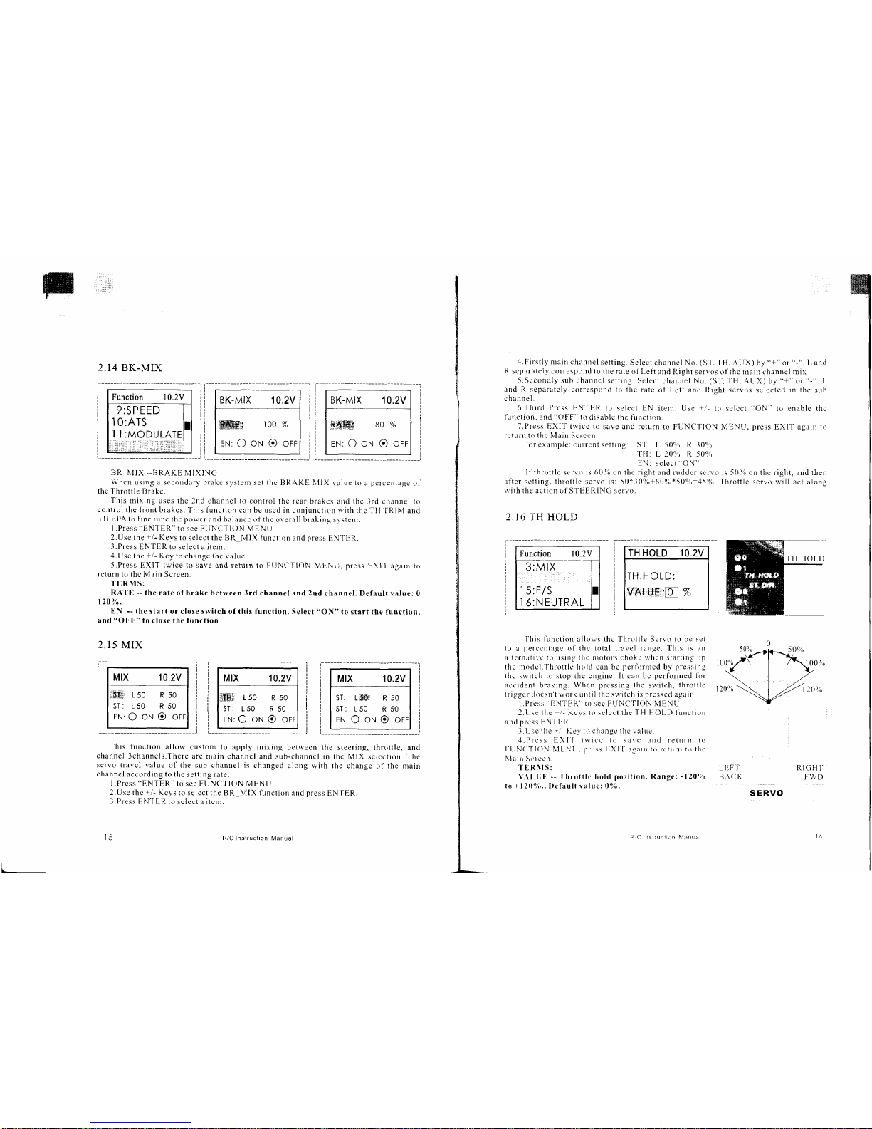
2.14 BK-MIX
Function 10.2V
9:SP EED
'10:ATS
BK.MIX 10.2V
w
100%
EN:
OoNOort
BK-MIX
10.2V
:8*W
80
%
EN:
Ootrt Oorr
BR_I\tIX
--BRAKE
MIXING
When
using a secondary brakc
system set
thc BRAKE MIX
ralue
to a pcrcentage
o1'
thc Throttle
Brakc.
This
mixing uses
thc 2nd channel
to
control
the rcar
brakes and
thc
-lrd
channel
to
controlthefrontbrakcs.Thisfunctroncanbeuscdinconjunctionri'iththcTII
fRItvland
TII IIPA
to finc tune
thc
power
and
[raluncc
oft]rc
overall braking
svstenr.
LPress
"ENTER"
to see FUNCTION MENU
2.Use the
+/-
Keys
to se
lect
the BR
MIX
firnction
and
press
ENTirR.
.l.Press
TNTFR lr) selcct r ilem.
4.Use
thc
+1-
Key
to change the
value.
5.Press
EXIT twice to save and
return to FUNCITION
iVIENU,
prcss
F-XIT agrrr)
trl
return
to
thc Main Screen.
TERMS:
RATE
--
the rate
ofbrake
between 3rd channel and 2nd
channel. Default valuc:
0
1200 .
EN
--
the start or
close
srvitch
of this function. Select
start th€
function.
and
"OFF"
to close the
function
2.I5
MIX
Mtx 10.2v
150 R
50
ST:150 R50
EN:O
oN O orr
Mlx 10.2v
Sllii
Lso
R50
ST:150
R50
EN:
OONOorr
Mlx 10.2v
ST: LSI':
R 50
ST:150
R50
EN:
OONOOTT
This
function allow
custom to apply mixing
betrvecn the
steering, throttle, and
channel
3channels.There
arc
rlain
channcl and sub-channcl
in the MIX
sclcction. The
servo travcl value
of the sub chanuel is
changed
along with the change
of the
main
chrnncl
rcct'rding l() lhc
setting rate.
l.Prcss
"ENTER"
to
sce
FUNCTION
MENU
2.Use the
+.1-
Kcys to selcct the
BR MIX
f-unctron
and
press
EN'f E,R.
l.Prcss
l- NTER ro
sclcct
r ilcrn.
t5 R/C
Instruction l\.4anual
i1/C
nsliu.i an
I\4anLra
w
.l.Frrstlv
main
channel setting.
Sclect
channcl No.
(ST.
TH.
-ALf X) by
"+"
,rr
"-".
L ancl
R
sL-paratcly cort
espond
to
the rate ol
Lett
and R
ight
serr os oithc rlain channel mix
5.Secondly sub
channcl settrng.
Sclect
channel
No.
(ST.
TH. AUX)
by
"+"
sp
"-".
1
and R separatcly
correspond to
the
ratc
o1'l-ctl and Right servos
selcctcd
in the
sub
channel.
(r.Third
Prcss I:NTER
to selcct EN
itenr. Usc
+r'-
to sclcct
"ON"
function. and
"OFF"
to disablc
the function.
T.Press EXIT l$'ice to
save and return
to FUNCTION N,lENU.
nress
to enable
thc
EXIT again
to
re
turn t()
thc
Main
Scrccn.
For exarnple:
currcnt
s!'tting
ST: L50'li, R30-q.i,
Tfl:
t- 20% R 50%
EN:
sclect
"ON"
ll'throttlc serro is 609i,
on tllc
right
and ruridcr scr'"o is 5()% on thc
light, and then
alter setting. throttle scrvo is:
50*30?6+60%*50%-45%. Throttlc servo will act
along
$'ith the action crl'STEERING
serr
o.
2.I6 TH HOLD
Function 10.2V
l3:MlX
,
.
:'.i':',-'
l5:F/S
i
6:NEUTRAL
TH HOLD 10.2V
TH.HOLD:
AIU€,,:E %
--Thts
function allorvs thc Throttle Servo to
be set
to
a
llerccntage
ol thc total travel
rangc.
This
is an
alternativc to using the rlrotots choke
u,hcn
stafting up
thc rnorlel.Throttle hold can be
perforrncd
bl
pressing
tirc
switch to stop the cngine. It
can
bc
pcrfbrnred for
accident
braking. When
prcssing the
switch,
throttle
trigger
(locsn't
rvork
Lrrrtil thc srl,itch
is prcsscd
atrin.
l.Press
"llNTF.R"
tu
scc FUNt"f
ION
IVlENU
LLlse
lhe
+/-
KL-vs
to selccl
the
TH
HOLD lirnction
ancl prcss ENI'trR.
l.I-lsc
the
-i-
Kev
1o
change thc valrre .
':l.Prcss
EXII-
trvicc
to sa\c and retLrrn tc,
FilN('TION*
MENI
l.
prtss
IIXIl'aqaill to rctunl l() thc
lvlrin
Serccn.
I'E R
\I S:
VAl.tr l.
--
'l'hrottle
hold
poiition. Range:
-l20ul,
tn
+12{)"1,..
I)ofaull
r aluc:
0o1,.
L I1
F'f
F},\C'K
RIGHI'
FWD
SERVO
TH.HOLD
Page 10
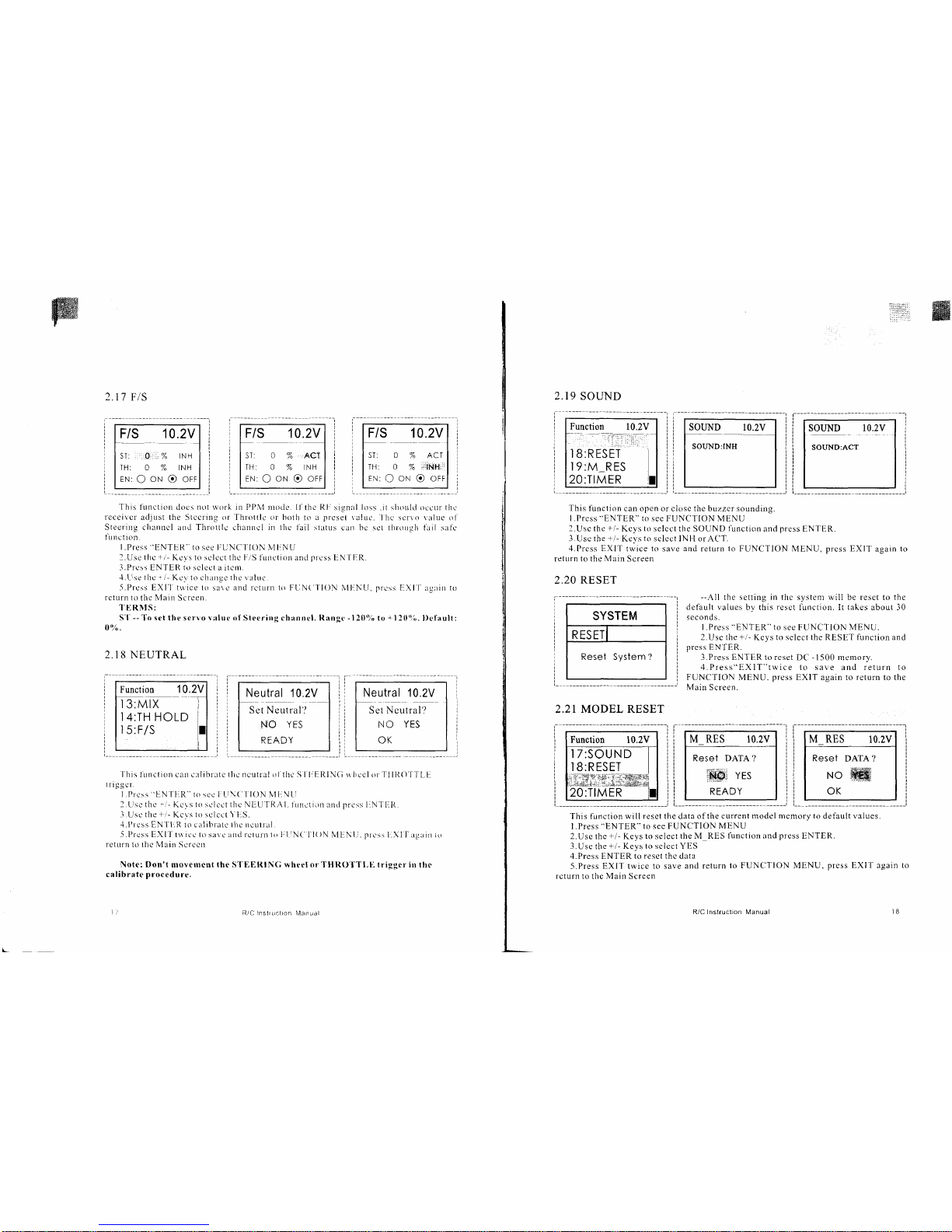
'J'his
function doe s
not
work in PI'\,{
rnode'.
I1'lhc Rl'
signlrl
loss
.it
shoulti oe
cur
llrc
receivcr
adjust the Stccring or Thlottlc or bolh
to
a
prcset
raiuc.
lhc sc1'\o value ol
Steering
clttnncl antl Throttlc cltanncl in tlrc
tail
stutLrs
can bc sct throLrgh tuil safe
lunctl0n.
LPress
"ENTER"
to see IiUNtITION
lvlINU
2.Use
thc
+i-
Ke
ys
to se lect the [rr'S
function and
prcss
EN'IF.R.
.l.Prrsr FNTER t() sclce I
J itrnt.
.l.Llse
thc
r
/-
Ke\ Io charrcc the valur..
-5.f'rcss EXI']'ttvice to
sare
and
rctunr
to
FLjN(
l-lOr\
i\,ll-.NLl,
prcss
EXI'f
rlrril
to
rctrlrn 1o
thc
Main
Screen.
I'E
R NI
S:
S'l--- To set thc servo lalur: of Steering channcl. Rangc - 120'%
to
+
120'ii.
l)efault:
0,'4.
2.18
NEUTRAL
2.17
FtS
Fis 10.2v
SI:
.",O,,,:-%
lNl-l
TH: 0 % INH
EN:
OONOOTT
F/S 10.2V
ST: 0 % ACT
TH: 0
7 INH
EN:
OONOOFF
Neutral 10.2V
S(r t Neutral'l
NO
YES
READY
F/S
10.2V
ST: A
%
ACT
TH: O
%
irlitH::i
EN:
OoNOorr
Neutral 10.2V
Set Ncutral?
NO YIS
OK
Xlf rgrir iLr
Function 10.2V
l3:MlX
l
l4:TH HOLD
l5:F/S
'l
his tunction car)
!'rlitl'atc tlrc ncutral o l'the-
S I Ir ElLlNCi s hccl or TIII{()'f
T[-L
triggcr'.
Prcss
'EN
f
IrR"
to scc I
LI\(l
l lON
l\1IrNti
L.rsc
thc','-
Kc\s
lo sclcct thc NIU]RAL
tirnction and prcss INTI]lt
Usc
the
+r-
Kcvs
to
sclcct
Yl:S.
I'rcss EN'f l:R
to
calibnrtt'the ncutral.
I'rcss EXll-1$ icc lo savc rnd rctunt 1() IitiNt l l()N
M[:Ntr.
plcss
I
return
t() thc Main Scrccn
Note:
Don't mov€tilcnt
(hc
STEERIN(i rvhecl orTHR()TTLE trigger in
thc
calibrate
procedure.
R/C lfslr uctron
Nrlanual
R/C lnstruction l\y'anual
2.19
SOUND
Function
10.2V
..:
-
t,i.ii:aa.it:rj
l8:RESET
19:M_RES
20:TIMER
SOI,IND
10.2V
SOUND:INH
SOUND 10.2V
SOUND:ACT
This
function can open or closc the buzzcr sounding.
l.Press
"ENTER"
to
see FUNCTION MENU
l.Usc
the
+,/-
Kcys
to
selcct the SOUND
function
and
press
ENTER.
3.Usc the
+/-
Kc),s
to
sclect INH orAC'T.
,{.Prcss
EXIT
twice to save
and
return to FUNCTION
MENU,
prcss EXIT
again
to
relrlrn to the Main Screen
2.20 RESET
SYSTEM
RESET
Reset Syslem ?
2.2I
MODEL RESET
--All
the
setting
in thc
system will be reset to
the
default values
by this
reset
function. It
takes
about l0
seconds.
l.Press
"ENTER"
to
see FUNCTION
MENU.
2.Use the
+/-
Kcys
to select the RESET function and
press
EN'fER.
LPress ENTER to reset
DC - 1500
memory.
4.Press"EXIT"twice to save
and
return to
F'UNCTION MENU.
press
EXIT again to return to the
Main
Screen.
Function
10.2V
I
Z:SOUND
I
8:RESET
*Xn:{*XSA{
20:TIMER
M RES 10.2V
REset DATA
?
&&i
vrs
READY
M_RES
10.2V
Resel
DATA?
NO
.W
OK
This function will
reset
the data
of the current moclel
mcmory to
default
values.
l.Press
"ENTER"
to see FUNCTION
MENU
2.Use
the
+/-
Keys
to select the
M RES
llnction
and
press
ENTER.
3.
Usc the
+/-
Keys
to
sclcct YES
4.Press ENTER to
reset the
data
5.Press
EXIT
twice
to save
and return
lo FUNCTION MENU,
press EXIT
again
to
rcturn to
the
Main
Screen
Page 11

2.22
TIMER
Function
10.2V
l7:SOUND
l8:RESET
l9:M_RES
TIMER
10.2V
MODE:INH
T: 0 m
0 s
TIMER
10.2V
MODE:
DN_T
1:12m
43 s
I t;
tl
tl
tl
Usc the tirner
by selecting
one
of the two
rinrcrs
up
rIMER
and DowN
TIMER..
and
if thc
MODE is
INH,
lt u,ill
close the
TIMER
Function.
l.Press
"ENTER"
to
see FUNCTION
MENU
2.Use the
+/-
Keys to
select the
TIMER
function
and
nress,.ENTER".
LPress
FN
f
ER ro selecr
a irem.
4.LIse
the
+i'-
Kcys to
cltange
the r
aluc
5.Press
"EXlT"
twice
to
save and
rourn
to FUNCTION
MENU, press..EXIT,,agarn
to return
to
thc
Main Screerr
UPTIMER
function
-
Prcss
"ENTER"
ro
select thc
MODE.
Use
+/-
Keys
to select
up r.(up
rIMER).
Thc UP
TIMER
carr
be uscJ
lo count rhc
time frorir
0 minurc
0 second
l. rhc
slon
timc.
Tlrc slop
time is
set form
fronr
0 minute
0
second
to 99 minute
30 secontl.
-
Thc flrst
start
operation
will
be linketl
to the
throttlc
trigger.
-
The
passage
ol'tinle
rs annotrnced
by
sounding.fa
buzzer
each minute
aftcr
sta rt
i ng.
-
Thc buzzer
rvill
sound'B-B-B...'
when
the
timer
is up Io the
stoD time.
DOWN TIMER
functiun
-
Pres.s
"ENTER"
ro
select thc
MODE.
Use
+/-
Keys
to
select
DN T.(DOWN
TIMER).
-
Thc DOWN
TIMER
can be used
to count
the time
from
presct
time 0
minute
0
second.
The
preset
time
is
set
form
0 minute
0 second to
99 rninutu,
J0 second.
-
Thc
firsl
start operation
will
be Iinketl
to
the throttle
trigger.
-
The passage
oftirne
is announced
by sounding
of
abuzzer
cach minute
after
starting.
-
The
buzzer
will sound'B-B-8...'
when
thc
timer
is
down t.
the 0 minute
0
second.
-r
R/C Instruction
lvlanual
R/C lnstnlct
on
Manual
2.1
1 Trim
ADJ.
"/
Please
start
the
motor
or the
engine
rvhile
making
the adjustment
of these settings.
I .clonncct
the recciver,
servos,
ancl
other
componcnts
and then
turn
on
rhe
powor
srvitches
to
transntitter
and receiver.
2 llc
sttrc
the
Stccring
trim
and
Throttlc
trini
on thc
transmifter
are at thcir
neutral
posltlon.
3.whcn
turning
on the tra'smitter,
pleasc
make
sure thc
lrans'rifter
antenna
i:,
cornpletely
cxtcnclcd.
Turn
on the transmitter
betirre
turling
on the
receiycr.
while
turn
off
the recciver
bcfbre
turning
olTthe
transmitter.
Steering
Trinr
Stecring
neutral
adjustnlonts
can be made
by moving
the steeling
trim
knob
to the lett
or
the right.
Raccrs
Tip
Alu'avs
check and
be sure the
servo is
at its neurral position
bcfbre
installing
a sen,o.
Adjust
the
scn'o
hom hole
position
and
linkage so
both arc
parallel.
When
a-servo
savcr
is
used
place
it as closer
to center
position
as
possible.
Be
surc thc-
steering
rrim
on thc
transmrtler
at the
ueutral
pOsitiOn.
.
Trirn
()peratiotr
And
Maxirnurr
Trav.
Changing
thc trim
can efl'ect
the
ovcrall
scttings, u,hen
adjustlncnts
are
ntade with
ilrc
trirrs.
plcasc
recheck your
inslallation
for
nraxinrun]
servo travel.(Srcctlng
EPA righl
side
and
ieli
side
).
Whcn
Trim movelnent goes
to
cxttemes
l'hat
means
if
you
makc a lot
of trint movement
t.,
sg1
3 sg1r.
to the neutral
position.
please
reposition
lhc scrvo honr
or
servo
saver on thc
selo and
inspect
-v-our
linkage
insta I lat
ion.
Throttle
Trim
?
/1'j
Throttlc
ne'utral ad-iustmcnts
can bc madc
by moving
the throttlc
trim to
the left
or thc
ngnr.
Racers
Tip
when
rrsing a clecllonic
speed
control, plcasc
sct tlrc
throttlc
lrim to neutral
and nrake
adJustrnents
to thc
speed control.
on a
ers
powcrcd
rlodcl, sct
the trinr tn
neutral and
adjust
the linkagc
to thc
point
u,here
carburctor
rs
tirlly closcd
in accordance
with the
engine
instruction
ntanual.
Trinr
Oleration
and
Travcl
'rrinr
ad.jtrstrncnts
rvrll
cll'ect
thc overall servo
travel.
so
pleasc
chcck the
(back-ward)
rlrovenrcnt
aftcr
tlrc
ad
justrncnt
Whcn
t|irn
ntoYct)tcnt
is
gocs
to
cxtremcs
That tttcans
if'vtru
nrakc a
l()t
oi-thc trit.n
nrovenrent
to gct
thc
scrvo to thc
neutral
position,
plcasc
rcccnter the
scrvo honr
closcr to thc
ncutral position
and
inspect
vour
throille
linkagc.
Page 12
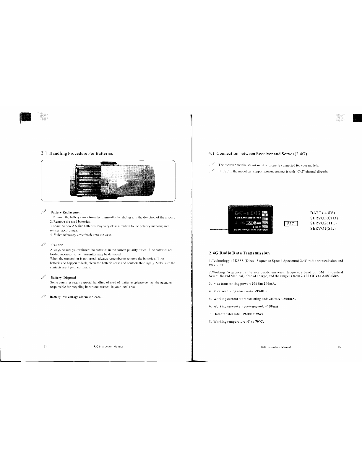
3. I Handling Procedure
For Batteries
," Battery
Replacement
LRcmove the
battcry
cover fionr
thc tl'ansmitter by sliding it in the
dircction
of the arrow
.
2. Remove
the used battcries.
3.Load the
ncw AA
size
batterics. Pay
very
close attcntion to the poluritl,marking
and
reinsert
accorclinqly.
4 .Slide
thc brttery covcr back onto the
case.
I Caution
Always
bc sure
vour
rcinsert
the
batteries in
the correct polarity
orcler.
Il'the
battcrics are
loaded incorrcctlv, the transmittcr
may be danraqcd.
Whcn the transrnittcr is not used
,
always renrember
to rcmove
the
b;rttcrics.
Ilthe
batteries
do happen
to leak,
clcan
the batteries casc and contacts thoroughly. Make
surc the
f()nlacts arc liec ol'cortrrsion.
a'" Battery
Disposal
Somc countries requirc spccial handling o1'used of batteries,please
contact
the
agcncres
responsiblc
fbr rccycling
hazarclous
wastcs
in
your
local
arca.
,1
Battery
low
voltage alarm indicator.
R/C InslrLlclion l,4anual
R/C
lnstruction
Manual
22
4. I Connection
between
Receiver
and
Servos(2.4G)
Thc
rcccivcr
and
thc servos
must be properly
connected fbr
your
models.
I1'
trSCl in
thc moclcl
can support power,
connect it rvith
"Ch2"
channel
directly
BATT.( 4.8V)
SERVO3(CH3)
SERVO2(TH.)
SERVO I
(ST.)
2.4G Radio Data Transmission
l.Tcchnology ofDSSS
(Direct
Sequence Sprcad Spectrurn) 2.4G radio transnrission and
recctVlng
2.Working frequcncy
is the worldwidc univcrsal fiequency band of ISM
(
Industrial
Scicntific
and Mcdical), free
of
chargc, and thc range
is fiom 2.400
GHz to 2.483 Ghz.
3.
IMax
transmitting power:
20dBm 200mA.
4.
Max.
receiving
sensitivity:
-93dBm.
5. Working current at transmitting end: 200mA-300mA.
6.
Working current at
reccjving end:
(
50mA.
7.
Data
lransl'er rate : 19200
bit/Sec.
8.
Working temperature: 0'to 70'C,
Page 13
BTtrITECT{
Distributed by:
Electus Distribution Ptv Ltd
320
Victoria Road
Rydalmere NSW
2116
Tel: 1300 738
555
Fac: 1 300
738
500
www.
electusd
istribution.
com. a u
DIGITAL PROPORTIONAL R/C
SYSTEM
 Loading...