

Page 1
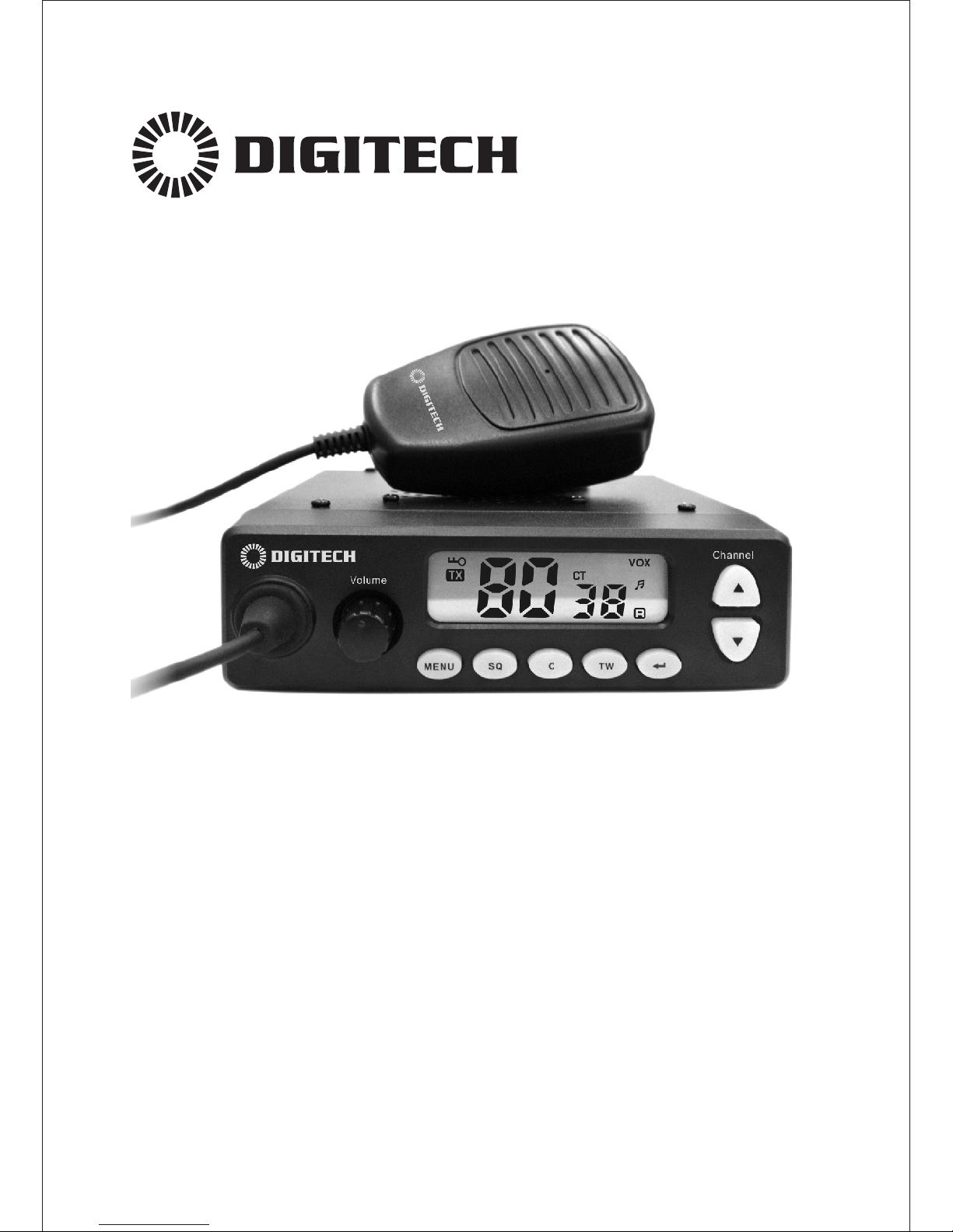
Model:DC-1120
Compact 5W UHF CB Radio
Instruction Manual
Page 2

Page 3

Introduction
-1-
Use of the citizen band radio service is licensed in Australia by
ACMA Radio communications (Citizen Band Radio Stations)
Class Licence and in New Zealand by MED General User
Radio Licence for Citizens Band Radio. Operation is subject to
conditions contained in those licences.
!
NOTE
Feature
80 channels
5W output power
38 CTCSS and 83 DCS
VOX function
Call tone melody (5 songs )
Rotary volume with power on/off
LCD back-light function
Key back-light
5 step adjustable and automatic squelch function
20 memory store
Repeater function
Key lock function
Key tone function (selectable on/off)
Roger tone function ( selectable on/off)
Triple watch function
Scan channel/Memory scan
Stop watch function ( <59’59”)
Page 4

-2-
Controls and Indicators
11 12
13
Front View
Rear View
ANT.
EXP. SP.
DC 13.8V
2
4
3
5
6
7
9
8
10
1
SQ
Channel
Volume
MENU
C TW
1. Microphone connection
2. Power ON/OFF and Volume Knob
3. MENU button
4. Squelch button
5. Call button
6. Triple watch button
7. Confirm button
8. Down button (Channel /Menu)
9. Up button (Channel /Menu)
10. LCD Display
11. UHF Antenna connection
12. Power Input connection (13.8V DC)
13. Ext. Speaker Jack
Page 5
Controls and Indicators
14 15
16
17
18
19
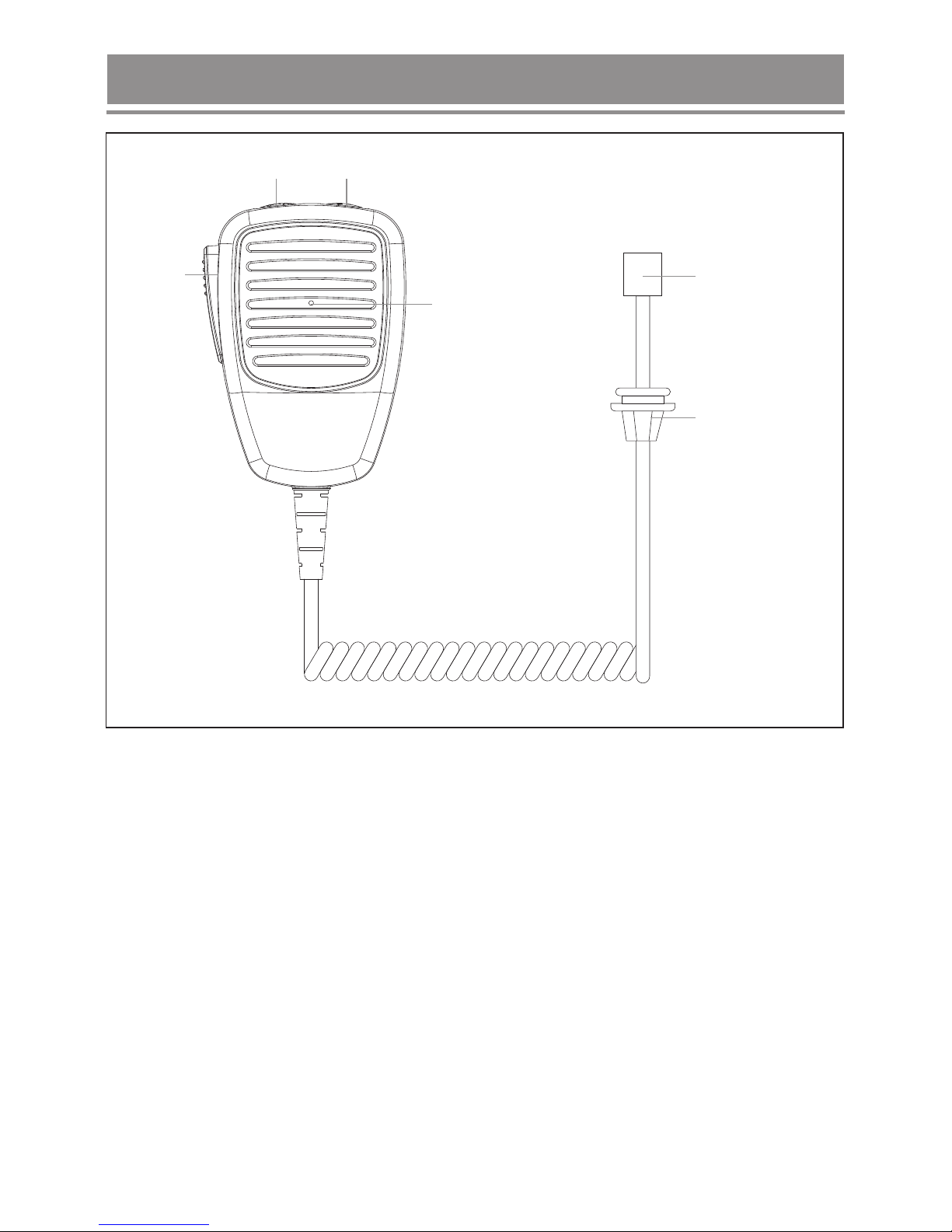
14. Channel Down Button
15. Channel Up Button
16. PTT - Push To Talk Button
17. Microphone
18. RJ45 Type plug
19. MIC Jack cover
-3-
Page 6
LCD Display
-4-
L
M ON P
Lo
A
F
B
C
D
E
G
I
J
K
H
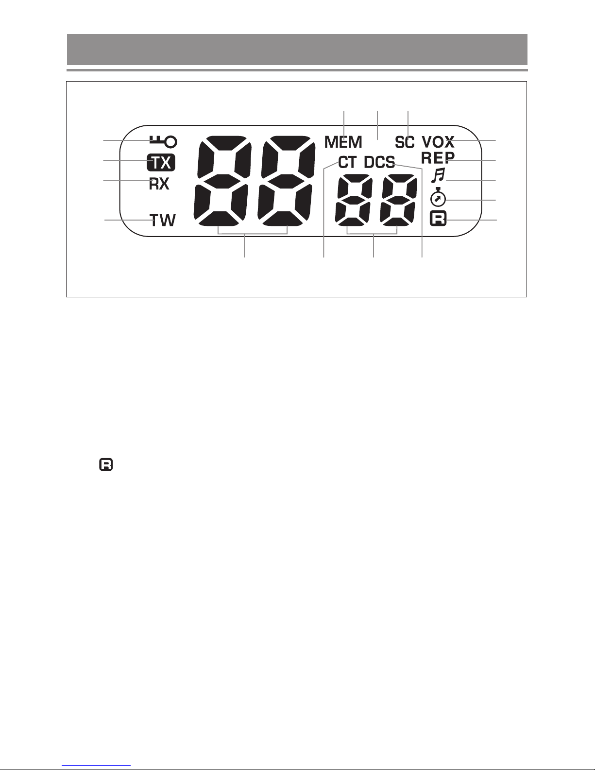
A. Keypad LOCK
B. TX Icon - is lighted when the radio is in transmit mode
C. RX Icon - is lighted when the radio is in receive mode
D.
E.
F.
G.
H.
I.
J.
K.
L.
.
.
.
.
TW Icon - Triple Watch function
VOX - Hands-free use
REP Icon -is lighted on when repeater function is switched on
Keypad Beep Tone
MEM -
Lo - indicates low power transmission
SC Icon - Automatic channels or CTCSS Code scanning
CTCSS - continuous tone coded squelch system
CTCSS & DCS code number
DCS - digital coded squelch
Stop Watch function
-Roger Beep function
Memory Indicator
Selected Channel Indication M
N
O
P
Page 7

Included with Radio
Standard Microphone
Instruction manual
Microphone Hanger,
Screws & Washers
Mounting cradle,
Screws & Washers
DC Power Cord
-5-
Page 8

Installation
-6-
Mounting the Cradle
Connecting the Microphone
Volume
The microphone uses a miniature 6 pin style plug and socket.
To connect the microphone:
1. Push the MIC plug at the end of the
microphone cord into the MIC jack
until the connection locks into place.
Gently tug the MIC cord to test
that the connection is locked.
2. Use the MIC Jack cover which
is threaded onto the MIC cord
to seal the MIC jack entry from
dust.
The cradle can be screwed or bolted in any convenient location in your vehicle
(under or above the dash, on the centre console, etc) using the mounting slots
provided in the base.
For maximum sound output from the build in speaker, we recommend the
cradle be mounted above the radio to minimize any obstruction of the speaker.
Avoid mounting close to heaters or air conditioners. Screw the mounting cradle
to a firm surface and put the radio into the cradle from the front until it clicks
into place.
Finally, connect the power cord and antenna cable to the sockets provided at
the rear of the radio.
Page 9

Mounting the MIC Hanger
The Microphone Hanger comes in two parts. How and where you mount the
MIC hanger will determine which parts to use.
Conventional Mounting with Screws
Conventional Mounting with Double Sided Tape
(not supplied)
Use the front part of the MIC hanger only.
Locate a suitable mounting position, mark
and drill two 3mm holes.
Fix the MIC hanger into place with screws.
High quality Double-Sided tape can be found at good retail stores.
Secure the front and back pieces of the MIC Hanger using the supplied
binding screws.
Locate a suitable mounting position.
Apply high quality Double-Sided tape onto the flat area of the MIC Hanger
back piece and then press firmly to the mounting position.
-7-
Page 10

Operation
Rotate the ON/OFF volume knob clockwise to turn ON and adjust the volume,
the radio is then going to self-inspection.
A series of tones will indicate the radio is on and full screen displayed 1 second.
If it is the first time to turn on the radio, the default parameter as below:
Parameter
Default setting
Channels
CTCSS privacy codes
DCS privacy codes
SQ levels
TX power
VOX on/off
Call Tone
Roger Ton e
Key Tone
Lock states
1
0
0
Auto
5W
OFF
5
ON
ON
Unlock
Rotate the ON/OFF volume knob counterclockwise until a click sound to turn
OFF radio.
Turning on the radio
Turning off the radio
Channel Selection
-8-
Press the or button to select the desired channel (1-80).
Press and hold the or button, the selection will move quicker.
Before selecting a channel for transmitting, always listen on it and ensure it
is not already being used. Always avoid selecting a busy channel when the
unit keeps on receiving signal from unknown party. The icon ‘RX’ will be
displayed.
Channel 5 and 35 are for emergency calling. Please do not use these
channels in non-emergency cases.
Speech telephony is inhibited on Channel 22 and 23.
Channel 1-8 and 31-38, 41-48 and 71-78 are used as repeater channels
with 750kHz offset. Channels 1-8 and 41-48 are used for mobile reception
and channels 31-38 and 71-78 for mobile transmission.
Page 11

-9-
Only use the repeater function when a long distance communication via the
local repeater facility is specifically required. Unless it is necessary, to
avoid operation on locally used repeater input channels (channels 31 to 38
and channels 71 to 78) or locally used repeater receiving channels
(channels 1 to 8 and channels 41 to 48) is recommended.
Channel 61, 62 and 63 are reserved for future use. They cannot be
activated until approved by the ACMA CBRS Class Licence in Australia.
In Australia,
Channel 11 is the customary calling channel for establishing
communication;
Channel 40 is the customary road vehicle channel.
Note:
This product is made to the new standard 2011 version.
There are possible operational issues during the changeover from the old
version 25kHz to the new verison of 12.5kHz channel spacing. They
include the consequences of narrowband (with 2.5kHz deviation)
transmissions being received on the old wideband equipment, and
wideband (with 5.0kHz deviation) transmissions being received on newer
narrowband equipment.
There is a possibility of interference due to the older equipment being
operated on channels adjacent to new narrowband channels.
The list of currently authorised channels can be obtained from the ACMA
website in Australia and the MED website in New Zealand.
Adjusting Volume
Rotate the volume knob to have the desire volume.
Receiving a signal
The unit is continuously in the RECEIVE mode when the unit is ON and not
transmitting.
When you receive a signal on the current channel, the RX icon is appeared
on the LCD display
Transmitting
Press and hold the button on the hand mic and speak gently to transmit
your voice. The TX icon will be displayed on the LCD display.
Time-out Timer
The unit will disable transmitting while the button pressed exceed 180
seconds.
Release and Press the button again to re-activate transmitting.
Page 12

-10-
Monitor
1. Press and hold the button more than 2 seconds to activate the Monitor
Function, you will hear background noise and possible weak signal from
the unit, when you released less than 5 seconds to return.
2. Press and hold the button more than 5 seconds to extended monitor;
3. Press the button once to return.
Squelch level setting
1. Press the button to set Squelch level,
2. Press the or button once to select the desired level
(Auto,1,2,3,4,5)
Press and hold the or button, the selection will move quicker.
Triple Watch setting
Press button to scanning current channel and channel 35 and 5;
2. Press button once to return.
Unless it is necessary, to avoid operation on locally used repeater input
channels (channels 31 to 38 and channels 71 to 78) or locally used repeater
receiving channels (channels 1 to 8 channels 41 to 48) is recommended.
Sending a Call Tone
With the unit in normal mode, press the button.
The microphone will be muted and the unit will transmit the current Call tone
to other users with the same channel and CTCSS code.
The TX icon will be displayed on the LCD display.
Call tone can only be transmitted once (not more than 3 sec) in any 60 sec
period.
It means that the unit will not transmit a call tone more than once no matter
how many times you press the button within a minute.
Triple Watch mode monitors channels 35 and 5 for a signal while you listen to
the currently selected channel.
1.
Repeater function
Repeater facility is a third party facility which is only available in some local
areas.
Only use this function for extending your communication range when you
know the channel of the repeater facility in your area.
Push and hold the Call key to activate the Repeater function, push and hold
the Call key again for release the Repeater function.
Page 13

-11-
CTCSS code setting
The radio has 38 CTCSS private codes available. Different CTCSS tones may
be associated to different channels.
To choose the desired CTCSS code, please proceed as follow.
1. Press button one time, the CTCSS code number blinks on the LCD
display. The CTCSS code indicates that no CTCSS tone is programmed on
that channel.
2. Press the or button to select the desired CTCSS code number.
Press and hold the or button, the selection will move quicker.
Selecting a CTCSS code will enable the CTCSS feature. To communicate
between two or more radios, both the channel and CTCSS code selections
must be the same.
To communicate with other models and brands of radios, the actual radio
frequency and CTCSS frequency must be matched.CTCSS codes on
Emergency Channel 5 and 35 are inhibited.
DCS code setting
The radio has 83 DCS private codes available. Different DCS tones may be
associated to different channels.
To choose the desired DCS code, please proceed as follow.
1. Press button two times, until DCS code number blinks on the LCD
display. The DCS code indicates that no DCS tone is programmed on that
channel.
2. Press the or button to select the desired DCS code number.
Press and hold the or button, the selection will move quicker.
DCS codes on Emergency Channel 5 and 35 are inhibited.
HI/LOW power setting
This feature permits the selection of the transmitting power level .
Before transmitting a speech to other units, press the button three times
to select the desired power output 5W.
VOX (Voice activate) setting
In VOX mode, the unit will transmit a signal only when it is activated by your
voice or other sounds around you. The unit will transmit for a further for 1
second even if you stop talking.
To set the VOX sensitivity level:
1. Press button four times, the icon will display and the current VOX
level will start blinking on the LCD display.
2. Press the or button to select the VOX level sensitivity. The highest
sensitiving level is 5.
Page 14

-12-
Memory setting
1. Press button five times, until the icon is displayed and channel
number is blinking.
2. Press or button to select desired channel, then press button to
confirm the channel.
The most channel you can store 20 channels.
Channel scanning
Channel scan performs searches for active signals in an endless loop from
channels.
1. Press button six times, the , channel number and CTCSS number
icons will start blinking on the LCD display.
2. Press the or button to activate the channel scan mode.
The channel number on the LCD display changes rapidly until an active signal
is detected.
When an active signal is detected, channel scan pauses on the active
channel.
CTCSS code scanning
1. Press button seven times, until the icons displayed and CTCSS
code will start blinking.
2. Press or button to start the CTCSS code scanning.
DCS code scanning
1. Press button eight times, until the icons displayed and DCS code
will start blinking.
2. Press or button to start the DCS code scanning.
Memory scanning
1. Press button nine times, until the icon is displayed.
2. Press or button to scanning.
Page 15

-13-
Call Tone setting
Call tone can only be transmitted once (not more than 3 sec) in any 60 sec
period.
It means that the unit will not transmit a call tone more than once no matter
how many times you press the button within a minute.
The unit is equipped with 5 user selectable Call tone melodies.
1. Press button ten times, until the C indicated and call tone code will
start blinking.
2. Press or button to set the desired melody, between the 5 available
melodies.
3. Press the button to transmit the Call Tone Melody.
Roger Beep Tone setting
The radio is equipped with a user selectable Roger Beep Tone feature, which
enables you to send a Beep Tone at the end of each transmission after every
release of the PTT Key.
This will prompt any receiving unit that your transmission has ended.
1. Press button eleven times, until the icon and the ON or OFF
indications will start blinking on the LCD display.
2. Press or button to set the desired selection ON (Roger Beep tone
enabled) or OFF(Roger Beep tone disabled). If the Roger Beep function is
enabled, a beep tone is heard to confirm the selection.
When the Roger Beep tone is enabled, the tone icon appears on the
LCD display.
Key Tone setting
When a key is pressed, a beep tone is heard to confirm your command. The
user many enable or disable this key tone.
1. Press button twelve times, until the icon and the ON or OFF
indications will start blinking on the LCD display.
2. Press or button to set the desired selection ON (Key tone enabled) or
OFF(Key tone disabled). If the Key tone function is enabled, a beep tone is
heard to confirm the selection.
3. When the Roger Beep tone is enabled, the tone icon appears on the
LCD display.
Page 16

-14-
Stop Watch Setting
Press button thirteen times, until 00:00 indications and
the icon will start blinking on the LCD display.
1. Press button to start the timer.
2. Press button to stop the timer
3. Press button again to re-start.
Key Lock
Press and hold the button for 2 seconds to activate/deactivate the Key
Lock feature, the icon will appear/disappear on the LCD display.
Page 17

Channel Table
-15-
Channel
Number
Frequency
(MHZ)
1*
2*
3*
4*
5*
6*
7*
8*
9
10
11
12
13
14
15
16
17
18
19
20
21
22+
23+
24
25
26
27
Channel
Number
Channel
Number
Frequency
(MHZ)
Frequency
(MHZ)
28
29
30
31*
32*
33*
34*
35*
36*
37*
38*
39
40
41*
42*
43*
44*
45*
46*
47*
48*
49
50
51
52
53
54
55
56
57
58
59
60
61
62 +
63 +
64
65
66
67
68
69
70
71*
72*
73*
74*
75*
76*
77*
78*
79
80
++
+
+
476.4250
476.4500
476.4750
476.5000
476.5250
476.5500
476.5750
476.6000
476.6250
476.6500
476.6750
476.7000
476.7250
476.7500
476.7750
476.8000
476.8250
476.8500
476.8750
476.9000
476.9250
476.9500
476.9750
477.0000
477.0250
477.0500
477.0750
477.1000
477.1250
477.1500
477.1750
477.2000
477.2250
477.2500
477.2750
477.3000
477.3250
477.3500
477.3750
477.4000
476.4375
476.4625
476.4875
476.5125
476.5375
476.5625
476.5875
476.6125
476.6375
476.6625
476.6875
476.7125
476.7375
476.7625
476.7875
476.8125
476.8375
476.8625
476.8875
476.9125
–
–
–
477.0125
477.0375
477.0625
477.0875
477.1125
477.1375
477.1625
477.1875
477.2125
477.2375
477.2625
477.2875
477.3125
477.3375
477.3625
477.3875
477.4125
Page 18

CTCSS Frequency Table
Sub
Channel
Frequency
(MHZ)
Sub
Channel
Sub
Channel
Frequency
(MHZ)
Frequency
(MHZ)
1
2
3
4
5
6
7
8
9
10
11
12
13
67.0
71.9
74.4
77.0
79.7
82.5
85.4
88.5
91.5
94.8
97.4
100.0
103.5
14
15
16
17
18
19
20
21
22
23
24
25
26
107.2
110.9
114.8
118.8
123.0
127.3
131.8
136.5
141.3
146.2
151.4
156.7
162.2
27
28
29
30
31
32
33
34
35
36
37
38
167.9
173.8
179.9
186.2
192.8
203.5
210.7
218.1
225.7
233.6
241.8
250.3
-16-
* Channel 5 and 35 are for emergency calling. Please do not use these sub-channels
in non-emergency cases.
+ Speech telephony is inhibited on Channel 22 and 23.
* Channel 1-8 and 31-38, 41-48 and 71-78 are used as repeater channels with 750kHz
offset. Channels 1-8 and 41-48 are used for mobile reception and channels 31-38 and
71-78 for mobile transmission.
Only use this repeater function when a long distance communication via the local
repeater facility is specifically required. Unless it is necessary, to avoid operation on
locally used repeater input channels (channels 31 to 38 and channels 71 to 78) or
locally used repeater receiving channels (channels 1 to 8 and channels 41 to 48) is
recommended.
++ Channel 61, 62 and 63 are reserved for future use. They cannot be activated until
approved by the ACMA CBRS Class Licence in Australia.
Page 19

64
65
66
67
68
69
70
71
72
73
74
75
76
77
78
79
80
81
82
83
532
546
565
606
612
624
627
631
632
654
662
664
703
712
723
731
732
734
743
754
DCS Frequency Table
Chann el
Numbe r
Octal
Code
1
2
3
4
5
6
7
8
9
10
11
12
13
14
15
16
17
18
19
20
21
023
025
026
031
032
043
047
051
054
065
071
072
073
074
114
115
116
125
131
132
134
43
44
45
46
47
48
49
50
51
52
53
54
55
56
57
58
59
60
61
62
63
315
331
343
346
351
364
365
371
411
412
413
423
431
432
445
464
465
466
503
506
516
-17-
143
152
155
156
162
165
172
174
205
223
226
243
244
245
251
261
263
265
271
306
311
22
23
24
25
26
27
28
29
30
31
32
33
34
35
36
37
38
39
40
41
42
Chann el
Numbe r
Chann el
Numbe r
Chann el
Numbe r
Octal
Code
Octal
Code
Octal
Code
Page 20

 Loading...