

Page 1

Digital Telephone System
System Manual
This publiiion is
following
CQ408 Rev. A and
Rev. A and kter
Rev. A and later
#IQ@mmt:
12
to the
Page 2
TABLE OF CONTENTS
Table
Of Contents
CHAPTER 1 SYSTEM OVERVIEW
SECTION 1 INTRODUCTION
SECTION 2 PUBLICATIONS OVERVIEW
....................................................
Related Publications
SECTION 3 HARDWARE SUMMARY
Common Equipment Description
Station Description
SECTION 4 GENERAL SPECIFICATIONS
................................................... l-2
....................................................
.........................................
............................................
.............................
..................................
....................................
.................................. 1-8
CHAPTER 2 DESCRIPTION OF SYSTEM FEATURES
Abandoned Hold Release
Access Denied
Account Code Button
Account Codes Positive Verification
Automatic Hold For Intercom
Automatic Hold -Transfer To Intercom
Automatic Hold
Automatic Pause Insertion
Automatic
Automatic Redial
Automatic Station Relocation
Auxiliary Equipment interface
Auxiliary Ringer Interface
Background Music
Basic Key Service
Battery Back-Up
Battery Back-Up
Block Programming
Call Announce Wiih Handsfree Answerback
Call Costing And SMDA Reports
Call Forwarding
Call Forwarding
Call Pickup
Call Pickup
Call Transfer
Call Transfer
Calling Station Identification On BLF
Class Of Service Programming (From Main Station)
Class Of Service Programming (From VDT)
Service Program Printout
...................................................... 2-l
......................................................
...................................................
Transfer To Line
.....................................................
......................................................
Interface
On
All Calls
Personal
.......................................................
Directed
Group
Screened
Unscreened
................................................ 2-l
.................................................. 2-l
...........................................
..................................................
...................................................
....................................................
..............................................
.........................................
............................................
................................................
..............................................
..............................................
................................................
....................................................
Emulation
................................................
...................................................
..................................................
...................................................
.................................................
....................................................
...........................................
......................................
............................................
...............................................
...............................................
...............................................
..........................................
...................................
......................................
...........................................
............................................
.................................................
l-l
1-2
2
1-3
l-3
l-3
..................
2-1
2-1
..2- 1
2-1
2-2
2-2
2-2
2-2
2-2
2-2
2-2
2-2
2-2
2-3
2-3
2-3
2-3
2-3
2-3
2-3
2-4
2-4
..2
2-5
2-5
2-5
2-5
2-5
2-5
Page 3
Table Of Contents
Conferencing
Conferencing
Multiline
Unsupervised
.................................................
..............................................
....................................................
Default Functional Program
...............................................
..................................................
Delayed Ringing
Departmental Calling Distribution Report
Designated Programmable Buttons
Dial 0 For System Attendant
Direct Department Calling With DCD
Direct Inward Station Dialing
Direct Station Call Hold
Direct Station Selection Programmable
Distinctive Ringing
Do Not Disturb
Do Not Disturb Inhibit
Do Not Disturb Override
Dual Intercom
Dynamic Line Buttons
End-To-End Signalling On Intercom
End-To-End Signailing On Lines
Exclusive Hold
Exclusive Hold System-Wide Enable/Disable
Executive/Attendant Override
External Paging Interface
Feature Inhibit
Flexible Ringing Assignments
Flexible Ringing Assignments Of PA Port
.....................................................
........................................
...........................................
...............................................
...........................................
..............................................
.................................................
.........................................
....................................................
......................................................
..................................................
.................................................
......................................................
..................................................
..........................................
............................................
......................................................
.....................................
.............................................
...............................................
.....................................................
.............................................
.......................................
Flexible Station And Line Class Of Service Control
Flexible Station Numbering Plan
Full Button Programmability Of Features
Handsfree Answer Inhibit
...........................................
.......................................
...............................................
..............................................
Idle Line Preference
..................................................
.............................................
..................................................
Intercom Line Timeout
Last Number Redial
LCD Messaging
Line Access Restriction
Line Answer From Any Station (Night Mode)
Line Groups
......................................................
Line Preselection
Line And Line Group Queuing
Manual Hold
......................................................
Meet-Me Answer Page
Memory Retention Without Batteries
Message Waiting
Modular Wring And Jacks
.................................................
..................................................
....................................................
................................................
.....................................
...................................................
.............................................
................................................
.........................................
...................................................
...............................................
.....................................................
...............................
Music-On-Hold System-Wide Enable/Disable
.....................................
......................................................... ..2-13
Night
(Of Ringing)
On-Hook Dialing
....................................................
..............................................
..................................
....................
2-6
2-6
..2- 6
2-6
2-6
2-6
2-6
2-7
2-7
2-7
2-8
2-9
2-9
2-9
2-9
2-9
2-9
2-g
2-9
2-9
2-9
0
.2-l
o
o
.2-l o
o
o
.2-l
1
1
.2-l 1
2
.2-12
.2-12
2
2
.2-12
Page 4
Table Of Contents
Originating Denied
Personalized Ringing Tone
Pooled Line Access
Power Failure Transfer
Prime Line Automatic
Privacy
Privacy Release/Brokerage Service
Private Lines (Access Denied)
Programmable Direct Station Selection/Busy Light Field
Programmable Buttons
Pulse/Tone Switchable
Response Messaging
Remote Programming And Administration
Ringing Line Preference
Saved Number Rediat
secure Off-Hook Voice Announce Button
Secure Off-Hook Voice Announce Groups
Service Observing
Speakerphone Support
Station By Station Privacy
Station Message Detail Accounting
Station Message Detail Recording
Station Monitoring With DSS Call Pickup
Station Speed Dial
Station-To-Station Messaging
Subdued Ringing
System Alarm Reports
System Speed Dial
Tandem Attendant
Tap
Tenant Service
Timed Hold Recall
Toll Restriction (0 And 1)
Toll Restriiion (Flexible)
Toll Restriction (Night Mode)
Tone Or Voice Signalling (Intercom)
Transfer/Conference Button
Unanswered Call Transfer Recall Timing
Voice Announce Blocking
Voice Mail Transfer on Busy
Zone Paging (Via Station Speakers)
Designated Programmable Button
...................................................
............................................
..............................................
..................................................
................................................
.................................................
.....................................
..........................................
.............................................
...............................
................................................
................................................
.................................................
......................................
................................................
.................................................
...........................................
.......................................
......................................
....................................................
...................................................
................................................
..........................................
...............................................
..........................................
..........................................
.......................................
...................................................
.............................................
...................................................
.................................................
..................................................
...................................................
....................................................
.....................................................
....................................................
...............................................
...............................................
.............................................
..........................................
..............................................
.......................................
...............................................
..............................................
.........................................
3
.2-13
3
.2-13
3
.2-13
4
.2-14
.2-14
2-14
.2-14
.2-14
.2-14
.2-14
.2-14
4
.2-14
5
.2-15
.2-16
.2-16
6
6
.2-16
2-l 6
.2-17
7
8
8
8
.2-18
8
8
CHAPTER 3 INSTALLATION
Mounting Considerations
Mounting Procedure
AC Power Connection
System Grounding
Line Connections
Station Connections
................................................
...................................................
...........................
....................................................
....................................................
...................................................
................................
.............................
......................
V
3-l
3-l
3-3
3-3
3-5
Page 5
Table Of Contents
SECTION 2 OPTION INSTALLATION DETAILS
Key System/Hybrid Configuration
Power Failure Station Connections
Auxiliary Equipment Interface
Common Audible And Auxiliary Ringing interface
External Paging Interface
External Paging Interface
Data Device Connections
Music Interface
SECTION
3 ADD-ON EXPANSION MODULES
Introduction
Installation
.....................................................
......................................................
.......................................................
Line Port
SECTION 4 SOFTWARE CARTRIDGE ,
Introduction
Installation
SECTION
SECTION 6
5 DATA COMMUNICATIONS WITH THE DIGITALTELEPHONE SYSTEM
Equipment Required
Connections
Communications Procedures
Initial Condition
Checkout ......................................................
Resistance Check
General Check
Failure Isolation
......................................................
.......................................................
..................................................
......................................................
SYSTEM CHECKOUT AND FAILURE
....................................................
...................................................
Check
......................
.....................................................
....................................................
...........................................
..........................................
.............................................
...............................................
.........................................
...............................................
..................................
.............................................
...,...
...................................
..............................
,
......................
,
..........
,
..........
...........
3-14
4
6
7
8
9
3.23
3-27
3-29
..3-3 1
SECTION 7 FCC RULES AND REGULATIONS
CHAPTER 4 SYSTEM PROGRAMMING
SECTION
Programming Overlays
GENERAL INFORMATION
.................................................
SECTION 2 CLASS OF SERVICE PROGRAMMING
Master Clear
System Defautts
System Configuration
Line Configuration
Station Configuration
Direct Inward Station Dialing
Analog Terminal Interface
Toll Restriction Table Configuration
Data Printer Service
Integrated Call Costing
Station Message Detail Accounting Reporting
Attendant Configuration
.......................................................
.....................................................
..................................................
...................................................
.................................................
.............................................
...............................................
..................................................
................................................
................................................
...................................
..........................................
..............
.........
.............................
....................................
SECTION 3 VIDEO DISPLAY TERMINAL PROGRAMMING
..................
VDT Programming Procedure
Remote Programming
Typical PC Operation
Menu Descriptions
Main Menu Selections
...................................................
.......................
.................................................
.................................................
.................................................
...................................
,
...............
,
................
.......................
.....................
4-1
4-j
4-1
4.2
4-3
4.4
4-5
4-83
vi
Page 6
Table Of Contents
System COS Menu Selections
Line COS Menu Selections
Station COS Menu Selections
Toll Restriction Table Administration
CHAPTER 5 SYSTEM OPERATING PROCEDURES
SECTION 1 STATION OPERATION
Answering Calls
Making Calls
Holding Calls
Transferring Calls
Conferencing
Messaging
Voice Announce Blocking
Line Monitoring
Recall/Flash
Paging
Do Not Disturb
Personal Ringing Tones
Background Music
Automatic Call-Back
Service Observing
..........................................................
Executive Override
Speakerphone Operation
Departmental Station Operation
Station User Programming
.....................................................
.......................................................
.......................................................
....................................................
.......................................................
........................................................
.....................................................
.......................................................
......................................................
..................................................
....................................................
.....................................................
...................................................
.....................................................
...................................................
...................................................
............................................
..............................................
.............................................
.........................................
....................
.....................................
................................................
.............................................
.................................................
...............................................
............................................
...............................................
.4-87
.4-88
.4-89
.4-90
5-1
5-2
5-4
5-4
5-5
5-5
5-6
5-6
5-6
5-7
5-7
5-8
5-7
5-8
5-8
..5- 9
5-9
..5
1
1
SECTION 2 ATTENDANT STATION OPERATION
System Clock
System Speed Dial Programming
Night Transfer (Of Ringing)
Music On Hold
LCD Messaging
Station Names
Station Message Detail Accounting (SMDA) Printout
System Alarm Reporting
Direct Inward Station Dialing
.....................................................
...........................................
..............................................
.....................................................
....................................................
.....................................................
................................................
.............................................
.............................
.................................
SECTION 3 SYSTEM OPERATlNG CHARACTERISTICS
Feature Code Numbering Plan
Ringer
Status Indicators And Tone Sequences
Display
.................................................
....................................................
CHAPTER6 MAINTENANCE
Technical Assistance And Repair Service
Fuse Location
Wiring
Station Wall Mounting
.......................................................
..........................................................
..................................................
............................................
........................................
............................,...
........................................
5-14
7
.........................
9
6-1
6-1
6-1
6-1
Page 7
Table Of Contents
66
LIST OF ILLUSTRATIONS
Figure l-1.
Figure l-2.
Figure 1-3.
Figure 3-l.
Figure 3-2. AC Power Connection And System Grounding
Figure 3-3.
Figure 3-4.
Figure 3-5. Typical Station Connections
Figure 3-6.
Figure 3-7.
Figure 3-8. Auxiliary Interface Connections
Figure 3-9. Typical Common Audible Interface Wiring
Figure 3-l 0.
Figure 3-l 1. Typical External Paging Connection
Figure 3-12.
Figure 3-13.
Figure 3-l 4.
Figure 3-l 5.
Figure 3-l 6. Software Cartridge Installation and Removal
Figure 3-l 7.
Figure 4-l.
Figure 4-2. Call Costing Diagram
Figure 4-3.
Figure 5-l.
6-1.
Programming Overlays
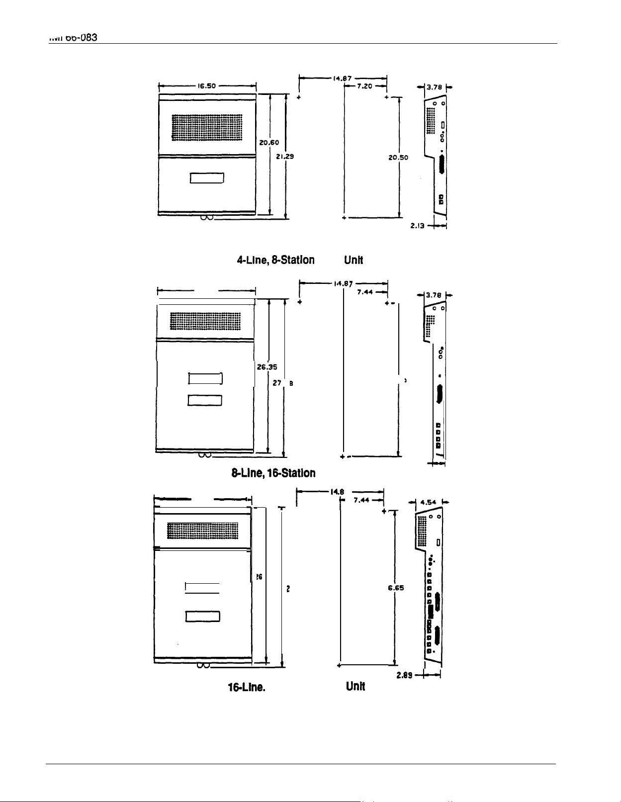
Outline Dimensions
Outline Dimensions
Station Images
Mounting Dimensions
Common Equipment, Station And Line Connections
Typical Line Connections
Key/Hybrid Configuration
Power Failure Connection
Typical External Paging Connection
Typical Data Device Connections
Music Interface
Expansion Module Configuration
Expansion Module Installation
Data Communications Interconnection Diagram
Location Of Keys On Telephone Faceplate
Remote Programming Block Diagram
Controls and Indicators
Station Wall Mounting Details
.............................................
Common Equipment
Station Equipment
..............................................
..........................................
........................................
......................................
.......................................
.......................................
....................................
Line Port
...................................
.............................................
.....................................
..........................................
.........................................
......................................
............................... l-5
................................
.............................
.........................
...............................
..................................
............................
...............................
.............................
............................
..............................
.................................
l-6
l-7
3-2
3-4
1
2
3
4
5
6
3-l 7
8
3-l 9
.3-21
.3-22
.3-26
3-28
4-49
.4-86
8
6-2
LIST OF TABLES
Table
Table 3-2.
Table 3-3. Station Connections (E-Line,
Table
Table 3.4b.
Table 3-5. Line Connections
Table 3-6.
Table
Table
Line Connections
Station Connections (CLine, E-Station)
Station Connections (16-Line,
Station Connections
Character Dialing Codes Chart
Character Codes
.............................................
408 Expansion Module
408 Expansion Module
....................................
............................................
.................................
................................
................................
...............................
..............................
.............................
3-6
3-7
3-8
3-9
0
3-23
6
Page 8

System Overview
CHAPTER
SYSTEM OVERVIEW
SECTION 1
INTRODUCTION
The digital telephone system is an expandable
communications system with many attractive
characteristics including the following:
Unitized base unit which includes all system
features.
self-contained.
Expansion modules which increase station and
line capacity.
available. It can be added singly or in pairs to
increase the station and line capacity of an existing
base unit installation.
Secure off-hook voice announce (SOHVA) feature.
The SOHVA feature allows a station user to talk to a
busy station without being heard by the outside party
at the busy station. The called user can easily send
back a pre-programmed LCD message or talk to the
caller without being heard by the outside party.
Programmable buttons.
buttons can be programmed to provide functions such
as direct station selection (DSS), auto dial, system
The base unit is full featured and
A 4-line, 8-station expansion module is
Many of the telephone
feature access, line access, messaging and more.
Programmed buttons helps station users eliminate
manual dialing errors.
Service
quality of service without interrupting calls by
monitoring a trainee’s call without being heard by the
distant party at the trainee’s station.
Handset volume control on all stations.
volume can be set to a comfortable listening level for
each individual user of the telephone.
Call cost display.
outside call costs. Special programming allows an
LCD speakerphone to display the accumulating cost of
a call.
Dual intercom.
provided so that station users can handle two intercom
calls at once. One intercom call can be placed on
hold while a second intercom call is serviced or both
calls can be conferenced together.
1
observing.
Supervisors can help insure
Handset
Built-in software records all
A second intercom key can be
Page 9

System Overview
SECTION 2
PUBLICATIONS OVERVIEW
MANUAL SCOPE
l
This publication contains a technical discussion of the
digital telephone system. Included in this manual is
the following information:
Chapter 1, System Overview:
This chapter
provides a generalized understanding of the
system, an explanation of the supporting
documentation, and a summary of the equipment
Related publications, which contain additional
information applicable to this system, are available
from the manufacturer.
They are as follows:
hardware.
Chapter 2, Feature Description:
This chapter
provides a detailed discussion of the features
GENERAL INFORMATION
l
provided by the digital telephone system.
Chapter 3, Installation:
This chapter provides
USER INFORMATION
detailed installation instructions and connection
details.
Chapter 4, Programming:
This chapter provides
detailed programming instructions for setting the
operating parameters of the system.
Chapter 5, Operation:
This chapter summarizes
l
l
l
operating procedures and provides special tone
and indicator details.
Chapter 6, Maintenance:
Special maintenance
details are provided in this chapter.
RELATED PUBLICATIONS
Electrostatically Sensitive
Components
GCA 70-l 82 Attendant’s Guide
GCA 70-l 83 System User’s Guide
GCA 70-l 84 Station User’s Guide
Page 10
.
au-u83
System Overview
SECTION 3
HARDWARE SUMMARY
The digital telephone system consists of an electronic
Key Service Unit (KSU) base unit, usually referred to
as common equipment, optional expansion modules to
extend station and line capacities as required, a
software cardridge containing the operating
programming, dedicated digital electronic key
telephones, and interconnecting wiring consisting of
small, 2-- or 4--conductor, twisted-pair cable.
The station and line capacity of the base unit and
optional expansion module are per the following chart.
MODEL
NO.
CO408 4
CO81 6
Cl 632
CO/PBX
CAPACITY
8
16
STATION
CAPACITY
8
16
32
CM408 4 8
The digital telephone system is full featured, and
supports the digital telephone models.
The digital system is expandable in both line and
station capacity with the addition of add-on expansion
modules. Refer to
Figure 3-14
on page 3-24 for an
illustration of the expansion configurations.
can be read. As the system clock goes through the
clock cycle, all necessary digital information is passed
between the pieces of equipment sharing the highway.
The common equipment consists of a base unit, which
provides complete feature support, and optional
expansion modules which provide extended station
and line coverage.
The wmmon equipment is contained in a functional,
modem-style metal housing of contemporary design in
keeping with the needs of the modem off ice
environment. It is engineered to be wall or rack
mounted. The outline dimensions of the common
equipment base units are illustrated in
The digital telephone stations employed with the
digital system are electronic, microprocessor-
controlled, devices. They allow not only multiline
pickup but also single key access to features available
from the serving CO, PBX, or
well as the wmmon equipment. The digital telephone
is available in two different images. The features of
the images are as listed below and as detailed in
Figure
The wide-image digital telephone provides the
COMMON EQUIPMENT
The common equipment base unit is a fully electronic
following features:
l
device. It is essentially a special purpose computer
l
system acting as a communications controller
between central off ice (CO), private branch exchange
(PBX), or
supplied lines and the proprietary
digital telephone stations. The software architecture
of the common equipment provides complete system
support
and
great flexibility of operation.
3 fixed buttons with indicators
. SPKR
l HOLD
.
3 fixed buttons without indicators
The system is fully digital and is ISDN up-gradable
with two usable time slots available for each station.
The digital information passes over time division
multiplexing (TDM) highways. The digital information
is an encoded version of the voice transmission and
control signals that are translated into computer
language. The TDM highway can transmit several
signals over a single pair of wires at the same time.
The signals are governed by a system clock. This
clock creates an overall point of reference against
which the TCM information is synchronized and
partitioned into time slots. A time slot is a portion Of
time assigned to a particular position of the system
clock. Each time a particular clock position
reached, the information associated with that position
Figure l-l.
STATION DESCRIPTION
switch
and in
Figure
l-3.
Full modular connection
l TAP
.
. MUTE
Programmable buttons with indicators
7-foot, G-conductor line cord
6 position, 4- or 6-conductor modular line jack
K-type handset (hearing aid compatible)
Ringer volume control (Off, Low, and High)
Wall mounting capability
as
Page 11

System Overview
The image designations refer to the number of
programmable buttons located below the keypad,
including the hold and intercom buttons, as opposed
to the number of programmable buttons located above
the keypad.
l
The 10x14 image provides a moderate sized line
button matrix along with a moderate sized priority
line button grouping. This image is best suited for
typical work area stations. The 10x14 image is
available in both monitor and speakerphone
versions.
l
The LCD speakerphone is available in a 5x14
image, This image provides a priority line grouping
and contains a liquid crystal display which shows
call handling data and other usefutinformation. The
LCD speakerphone is used as an attendant station
as well as being very applicable for use as an
executive station.
Page 12
Base Unit
System Overview
16.50
16.50
I
-7.44
26.25
q
2.13
7
+
i
0
27
-7.44
2
Figure 1-l. Outline Dimensions n Common Equipment
l-5
Page 13

System Overview
l-6
Page 14

0
l-7
Page 15
System Overview
SECTION 4
GENERAL SPECIFICATIONS
SYSTEM CAPACITY
LINES:
STATIONS:
INTERCOM PATHS:
MAXIMUM SIMULTANEOUS
INTERCOM CONVERSATIONS:
PAGING PORTS
PARK ORBITS
SPEED DIALS
SYSTEM
STATION
AUTODIALS
POWER FAIL CIRCUITS
(Maximum Combinations
At Any One Time)
POWER REQUIREMENTS
(Fully loaded system)
AC POWER:
4-LINE,
8-STATION,
4
8
(FUTURE FEATURE)
Non-blocking
Non-blocking Non-blocking
1
9 9
99
10
Unused buttons
1
1
five-way plus 1 three-way
plus 2 SOHVA
2 four-way plus 2 SOHVA
1
four-way plus 3 three-way
5 three-way plus 1 SOHVA
90
129 VAC Singlephase
8-LINE, 16-LINE
8
16
Non-blocking Non-blocking
1 1
99 99
10
Unused buttons Unused buttons
1 1
all models
16
32
Non-blocking
9
10
4 five-way plus 5 three-way
plus 1 SOHVA
6 four-way plus 2 three-way
3 four-way plus 9 three-way
16 three-way
DIMENSIONS (approximate)
COMMON EQUIPMENT
WIDTH (inches):
HEIGHT(inches):
DEPTH (inches):
WEIGHT (pounds):
STATIONS
FOOTPRINT (inches):
WEIGHT (pounds):
STATION CABLE REQUIREMENTS
TYPE:
MAXIMUM LENGTH:
SWITCHING PRINCIPLE:
7ow 135w
16.5 16.5 16.5
21.3
3.8 3.8 4.5
17.5 26
8.625 X 7.658
2.5
P-wire (l-pair) twisted, non-shielded.
1000 feet with 24 gauge wire
Digital, time division multiplexing (TDM). Provides non-blocking
switching with stored program control
27.1 27.6
150w
200VA
30.5
Page 16
TEMPERATURE:
32-122 degrees F (O-50 degrees C)
90 percent relative, non-condensing
STATION:
LINE:
RECORDING PORT
FORMAT:
PARITY:
DATA BITS:
STOP BITS:
BAUD RATE:
HANDSHAKING:
CABLE LENGTH:
MUSIC INTERFACE
INPUT LEVEL:
INPUT IMPEDANCE:
CONNECTOR:
PA PORT
OUTPUT LEVEL:
OUTPUT IMPEDANCE:
CONNECTOR:
CENTRAL OFFICE LIMITS
LOOP LIMfTS:
CABLE INSULATION LEAKAGE:
INDUSTRY/REGULATORY
STANDARDS:
Standard 50-pin male connectors for connection to external
distribution field.
Standard, G-conductor mini-jack (USOC 14C)
Serial, pseudo RS-232C
None
7 or 8 (programmable)
1 or 2 (programmable)
Programmable in class of service
Xon
Hardware
500 Feet maximum
3 Vofts peak-to-peak maximum
Approximately 500 Ohms
RCA phono jack
400 Millivolts peak-to-peak (typical speech)
Approximately 500 Ohms
RCA phono jack
CTS
1900 Ohms maximum loop
15,000 Ohms minimum
FCC Certified, part 15 (Class A)
FCC registered (fully protected)
LISTED by OSHA-accredited, nationally recognized, test laboratory
EIA RS478
Bell publication 48002 guidance
Hearing aid compatible handset
MEMORY RETENTlON
AFTER POWER LOSS:
FCC REGlSTRATlON NUMBER:
KEY SYSTEM:
HYBRID SYSTEM:
RINGER EQUIVALANCE NUMBER:
PRODUCT CODES:
CO408
CO81 6
Cl 632
CM408
a-Line, 16Station
4-Line, a-station
Expansion Module
60 hours minimum
1.38
7714X
1 OX14 Image Monitor
1 OX14 Image Speakerphone
Image LCD Speakerphone
ware
SO408
SO816
S1632
Page 17
CHAPTER 2
DESCRIPTION OF SYSTEM FEATURES
Svstem
ABANDONED HOLD RELEASE
If an on-hold party hangs up at the CO/PBX end of a
connection, causing an interruption in the line current,
the system will drop the line from the hold condition
and return it to service. The time interval between
hang-up and line-drop is programmable in line class of
service programming with choices of either 50 msec or
350 msec. This feature is usually dependent upon
special arrangements that must be made at the CO
end of the connection. The line select indicator will
turn off to indicate an idle line after a call on that line
hasbeenabandoned.
transferred. On transferred calls, the transferee is
associated with the call record. On incoming calls, the
last user active on a call is the one that is associated
with the costed call record. The system can be
programmed to place an appropriate message on the
display to remind users of LCD speakerphones to
enter an account code. Account codes may be from
three to eight digits in length as set by class of service
programming. When the user enters an account code,
the system will force the use of the programmed
length, but will verify only the first three digits to
determine validity.
ACCESS DENIED
Access to particular lines can be denied at certain
stations in the system through system programming.
A station user cannot select a denied line for use.
This feature is programmable on a per line/per station
basis in station class of service programming.
ACCOUNT CODE
Station class of service programming can be used to
assign an Account Code button to any programmable
button location at a station as part of the button
mapping procedure. With this Account Code button
available, the user can press it and then dial the
account code without interrupting the call. Only the
user of the Account Code button will hear the DTMF
tones when the code is dialed. The distant on-line
party will not hear the DTMF tones, and the line will
not be placed on hold. The distant on-line party can be
heard while the account code is being dialed.
ACCOUNT CODES WITH
POSITIVE VERIFICATION
Specific account codes can be assigned by station
users to specific types of calls. The account codes
are used by the system to identify calls by category, or
special grouping, for call recording purposes. All calls
with the same account code will be reported together
by the station message detail accounting feature.
The system may be programmed to verify the user
entered account code and sound an ermr tone if it is
incorrect. The system may be programmed by call
costing and SMDA reporting class of service
programming to permit station users to enter account
codes for incoming calls and/or out going calls if
desired. Account codes are entered while on line
either before an out going call is dialed or after the
distant patty on an incoming call has hung up. On out
going calls, the user who enters the account code is
associated with the call record except when the call is
All-call paging allows all stations to receive
announcements through the station speaker at once.
All-call paging is also sent to the paging port where it
can be applied to the input of an external paging
amplifier. Origination of announcements must be via
the station handset. Each station can be programmed
to receive and/or originate all-call page. The ability to
receive and originate all-call paging at a station is
enabled by station class of service programming. Also
see the discussion titled: Zone Paging.
Refer to the discussion titled: ExternalPaging
Interface.
This feature allows a station user to program a button
to be used for sending a message to an LCD
speakerphone. Once programmed, the station user
can press the ASSIST button at anytime and then
press a DSS button to sound a tone burst at the called
station and present a preprogrammed message in the
station display. A message can be sent while on a call
without alerting the distant party. This feature is useful
for requesting assistance while engaging on a call. For
example, a customer service representative could
request assistance from a supervisor while talking to a
problem caller. The supervisor, upon receiving the
tone and noting the display message, could perform
an executive override or service observing action to
join the call or monitor it.
If a busy tone is encountered after an intercom station
is called, a special code number can be dialed that will
cause the system to automatically ring the calling and
called stations when the called station becomes idle.
ALL-CALL PAGING
AREA PAGING INTERFACE
ASSIST
AUTOMATIC CALLBACK
2-l
Page 18

Of System Features
No class of service programming is required to enable
this feature.
AUTOMATIC DIALING
The system supports up to 22 auto dial positions per
station. Autodial buttons can store up to 16 digits plus
an intercom or line selection. Stored digits include
9-0,
and #. A pause is stored at any point where the
HOLD button is pressed, and a hookflash is stored at
any point where the TAP button is pressed. Automatic
dialing can be used to provide one-button access to
system features. No class of service
programming is required to enable autodialing. Also
refer to discussions titled: Automatic Pause Insertion,
Station Speed Dial, and Programmable DSS/BLF.
AUTOMATIC HOLD FOR INTERCOM
If the second intercom line is selected while a call is
active on the first intercom line, this feature causes the
first intercom call to be automatically placed on hold.
Station class of service programming is required to
enable this feature.
AUTOMATIC HOLD
TRANSFER TO
INTERCOM (ANSWER HOLD)
If the intercom line is selected while an outside line
call is active, this system feature causes the outside
call to be automatically placed on hold. No class of
service programming is required to enable this feature.
AUTOMATIC HOLD
This system feature is made available through
programming to selected stations. When enabled,
pressing any line button will cause an active line to
automatically go on hold. This feature allows a user to
move from line to line without having to press the
HOLD button to place any current calls on hold.
Station class of service programming is used to
enable this feature at the desired stations.
TRANSFER TO LINE
AUTOMATIC PAUSE INSERTION
When the system stores a dialed number for later
redial, it automatically stores a pause whenever the
user watts between digits for at least two seconds.
The automatic pause is inserted in the stored number
sequence at the point where the manual pause in
dialing occurred. The length of the pause is fixed at
two seconds by the system.
AUTOMATIC PRIVACY
A line can be made private or non-private through
programming. In the private mode, a station has
exclusive use of the line during a call.
can access that line unless it is included through
No other Station
the
use of the add-on conference feature. In the
non-private mode, another station with that line
appearance can gain access at the same time
(sometimes known as common line pickup). A line is
specified as private or non-private through the line
class of service programming. Through station class
of service programming, a line can be made
non-private at a particular station. Also see the
discussions titled: Conference
Release.
A busy number or unanswered call can be
automatically redialed by activating this feature. Once
automatic redial is activated, the station will select the
line, automatically dial the number, and wait for a
response. It will do this once a minute for
approximately 10 minutes unless deactivated because
that button or another button is pressed or the handset
is lifted. The feature cycle is timed and does not have
busy detection circuitry. Because of this, if operating
handsfree when the called party answers, the handset
must be taken off-hook to prevent the caller from
being cut off by the timing cycle. Automatic redial is a
designated programmable button position and must be
programmed by the user to be active but no class of
service programming is required.
With this feature, the system will automatically
recognize a particular station should that station be
relocated to a new station port. When installed at the
new pori location, the station will continue to provide
the same class of service parameters and respond
the same extension numbers as it did at the original
station port. This system feature is enabled with
system class of service programming.
A non-key system telephone device or a data device
can be connected to a line ahead of the common
equipment by using the auxiliary equipment interface.
The system can detect an off-hook condition in the
device connected to the auxiliary equipment interface,
and turn on the status light for that line at the button
system telephones.
line is busy and not available for station use. Auxiliary
equipment interface connections provide connections
to lines 2 and 4. Pressing the line button on a system
station cannot interrupt an external device unless the
line has been programmed to be non-private.
The auxiliary ringer interface provides “dry-contact”
relay closures which track the ringing pattern
Add-On and Privacy
AUTOMATIC
NUMBER OR UNANSW
OF BUSY
RED CALL)
AUTOMATIC STATION RELOCATION
AUXILIARY EQUIPMENT INTERFACE
does this to indicate that the
AUXILIARY RINGER INTERFACE
2-2
Page 19
Description Of System Feat!
activated when station port 17 rings or when ringing
sent to the paging port.
When programmed for station port
external device is often used to provide loud ringing.
When programmed for paging port ringing, an external
paging amplifier is usually employed. The system
supplies ringing tones to the paging port along with the
relay closures. The ringing tones can be sent to the
input of an external paging amplifier. The relay
closures can be employed to energize the paging
amplifier while the ringing tone is being sent to it.
System class of service programming is used to
choose either the paging port. or station port 17 for the
ringing port relay control. System class of service also
determines the type of ringing sent to the paging port.
Station class of service programming determines the
type of ringing sent to station port
discussions titled: Common Audible Ringer
and External Paging Interface.
7 ringing, an
Also refer to the
BACKGROUND MUSIC EXTERNAL
MUSIC SOURCE RE6
If an external music source is provided, background
music can be turned on and off at individual stations.
The loudness of the background music is adjusted with
the call monitor speaker volume control, and the
background music automatically turns off during calls.
No class of service programming is required to provide
this feature. Also refer to the discussion titled: External
Music Source.
BASIC KEY SERVICE
The system provides all of the basic, 1 A24ype, button
service features. These features are: selective line
pickup, common line pickup, muftiline pickup, and
hold. No special class of service programming is
required.
UIRED)
EMULATION
BATTERY BACK-UP
(CHASSIS, CABLE, AND BATTERIES)
Battery back-up assemblies including chassis, cable,
fuses, and batteries are offered as optional kits
(available from Comdial). The assemblies are
designed to connect directly to the unintenuptable
power source (UPS) interface located on the common
equipment chassis. No user intervention is required
with this feature, and no class of service programming
is required.
BACK-UP INTERFACE
Provision has been made for attaching a Comdial
provided optional battery back-up
uninterrupted system power in case of an AC power
to give full
loss. The switching and charge circuitry are in the
common equipment, while batteries, chassis, and
cable are packaged as a separate option. When
plugged into an active AC power source the common
equipment will constantly charge the attached
batteries. Built-in circuitry automatically switches to
battery power when AC power is lost. Wrth batteries at
full charge, a fully loaded system will operate for a
minimum of one hour without AC power.
A class of service assigned to a particular station or
line can be assigned to an entire block of stations or
lines with one programming action. This feature
eliminates the need to individually program stations
and lines wfth the same class of service. Block
programming class of service can be performed after a
station class of service or line class of service has been
programmed for a particular station or line.
CALL ANNOUNCE WITH HANDSFREE
The internal speaker at each station provides
call-announce capability over the intercom link. A
handsfree response to a call-announce call can be
made. This response is transmitted by the microphone
built into the telephone housing..
CALL COSTING AND STATION MESSAGE
The system provides buift-in, estimated costing of all
outside calls.
accounting (SMDA) printout reports of all costed calls
as well as displayed call costs on LCD speakerphones.
Call costing, in general, provides a means of
establishing costs to be applied to outside calls made
from system telephones. Call costing computes
charges for a call after it is completed. lt does not
restrict dialing as toll restriction does. Call costs are
based on a two-tier time rate and includes a line
surcharge cost. Allowances can be programmed for
call set-up and minimum call duration. The system
provides several ways of determining call costing
making it is possible to apply reasonable rates for the
entire country.
The system is arranged to automatically provide a
report whenever the costed call storage reaches 95
percent of capactty. Additionally, programming can be
effected that causes these reports to be printed
automatically at a specific time of day.
There are five different SMDA reports which can be
produced:
BLOCK PROGRAMMING
ANSWERBACK
DETAIL ACCOUNTING REPORTS
also provides station message detail
2-3
Page 20

System Features
l
Detailed report sorted by stations
l
Detailed report sorted by account codes
number or station name for the station from which an
intercom call was forwarded.
Line summary report
l
Department summary report
l
A general output of all records
Call forwarding on intercom allows a station user to
designate another station number (or the attendant
station number) to be the recipient of intercom calls
Upon completion of report printing, all records used for
the reports can be deleted. Any call records created
between the time the report printout was started and
completed will not be deleted. If the reports are not
deleted after they are printed, a later command to
delete records will delete all records at that point and
not just the ones that were printed in the previously
generated reports. Programming action can be taken
normally directed to that user’s station. For each
intercom call received while call forward is enabled, a
ring reminder (short tone burst) will be sounded at the
forwarding station to remind the user that the calls are
being forwarded. On LCD speakerphones that are
recipients of call forwarding, the display will indicate
the extension number or station name for the station
from which an intercom call was forwarded.
to always delete the records after they have been
printed. The attendant has the ability to request
particular reports to be printed at any time they are
required.
Account codes can be established to allow system
users to identify calls by category or by any other
desired grouping so that costing by that category or
grouping can be reported. Department numbers can
be defined and stations assigned to different
departments so that call cost reports can be produced
on a department-by-department basis.
Feature programming is provided in call costing and
SMDA Reporting class of service programming.
Stations are assigned to specific SMDA departments
through station class of service programming. The
LCD speakerphone display of costed calls is also
The call park feature is similar to a manual hold
condition. A call that is parked from a particular
station can be retrieved at any station in the system by
dialing the appropriate access code. (Note: the
retrieving station cannot have access denied to the
line on which the call appears.) Calls are parked and
retrieved within the system through the use of dialing
codes. The system provides nine parking circuits
(orbits). Call park, when used with the paging
features, allows a system attendant to direct calls to
roving personnel. A call that is left in a parking orbit
for preprogrammed length of time automatically
returns to a timed hold recall condition at the station
which originally parked the call.
enabled through station class of service programming.
CALL FORWARDING ON ALL CALLS
This feature allows a station user to designate another
station or the attendant station as the recipient of all
A station user can dial a code, followed by the
extension number of a ringing station, to answer the
ringing call.
calls normally directed to ring at the user’s station. If
enabled when night transfer of ringing is activated, the
night ringing assignment of the station is also
forwarded. Calls that are forwarded to a recipient
station can be forwarded again from that station to
another station. Thus, two levels of call forwarding on
all calls can occur, first, from station A to station B
and then, from station B to station C. For each
intercom call that is received while calls are forwarded,
a short tone burst will occur at the user’s station as a
reminder that call fotwarding is enabled. When a
programmable button is programmed to serve as a
call forward button, the associated LED will turn on
If a call rings to any station in a pre-programmed
group and another user in the group wishes to answer
the call, that user must dial the group pickup code to
answer the call. Four different groups can exist with
any number of stations in a group. Overlap is provided
by allowing stations to be in more than one group thus
enabling those stations to pick up for stations in more
than one group. Stations within the system are placed
in logical answering groups by programming action.
Group stations together using the station class of
service programming.
when the button is pressed to indicate that the feature
is enabled. If the call forward button is programmed as
a second level to a DSS/BLF button, the LED
indication is afways reserved for BLF indication. On
LCD speakerphones that are recipients of call
forwarding, the display will indicate the extension
Screened call transfer allows outside calls to be
transferred from one station to another, via the
intercom link, in one of two ways. If both stations have
access to the line, a common line pickup transfer can
CALL FORWARDING
PERSONAL
CALL PARK
CALL PICKUP
CALL PICKUP
DIRECTED
GROUP
CALL TRANSFER -SCREENED
.
2-4
Page 21
Description Of System
be effected. If the other station does not have access
to the incoming line, transfer can still take place using
the system transfer feature. For a screened transfer,
a call is transferred to another station with a
pre-transfer announcement by the transferring patty.
Transferring calls is accomplished with the
button. Also refer to the discussion
titled: Call Transfer- Unscreened.
code provided for this purpose. The station user can
program individual stations for speed dial, autodial and
direct station selection (DSS) by entering COS with a
code provided for that purpose. Thus, COS
programming is arranged with a hierarchical order
from the highest (the installer) to the lowest (the
station user) level wfth a higher level programmer
having the ability to do anything a lower level
programmer can do without exiting a current
CALL TRANSFER
An active call can be transferred to another station
without being announced. The transferred call will
camp-on to the other station where it will ring and
await an answer. The call will automatically ring back
to the transferring station after a programmable recall
period. There is no limit as to how many calls can be
camped onto another station. A transferred call will
only ring if the station is idle. The system class of
service programming determines the recall time for an
unanswered transferred call.
UNSCREENED,
programming mode. However, only the station user
can program the speed dial and autodial locations at
telephone.
All class of service (COS) programming is performed
from station 10 or 12. Any station and console
combination will function in this mode and provide
visual feedback with the LED associated with the
programming button. By employing an LCD
speakerphone, however, the programmer will have the
benefit of display prompts and verifications to simplify
and clarify the programming procedures. Class of
service programming access is as follows:
CALL WAITING TONE
The call waiting tone may be signalled to a busy
station to indicate that another station or the attendant
wants to contact the busy station. A special code is
dialed to activate the tone.
l
l
l
l
Installer dials: ITCM
# 7 4 6
Administrator dials: ITCM
Attendant dials: ITCM
User dials: ITCM
# 2 3 6
# 0
CALLING STATION
IDENTIFICATION ON BLF
Class of service programming can be performed using
instructions provided in Chapter 4, Sections
If the station number of a calling station has been
programmed into the direct station select/busy lamp
field (DSS/BLF) of a called station, the caller will be
identified by flashing at the corresponding BLF light.
The lights also indicate the status of the DSS
telephones: dark = idle, steady-on = in use, flash =
calling (or ringing when station monitoring is enabled),
and flutter = call back request (if feature is available.
An asynchronous, serial data terminal with an RS-232
interface can be used to effect class of service
programming through menu-driven procedures. VDT
programming provides a menu-driven approach to
programming as discussed in Chapter 4, Section 5.
No class of service programming is required for this
feature. Also refer to the discussions titled:
Programmable DSS/BL F and Call Messaging.
Connection terminals are provided to interface an
CLASS OF SERVICE PROGRAMMING
(FROM MAIN STATION)
Class of service (COS) programming is used by the
installer to configure and assign all system, line,
station, and special purpose operating features. The
installer enters COS programming by dialing an
access code over the intercom line. System
RS-232 compatible, asynchronous serial data printer
to the system. The connected printer will provide a
printout of class of service and toll restriction records.
The data prlnter service class of service programming
determines the nature and extent of each requested
printout. The system class of service programming
specifies the bit-length and baud rate of the data.
administrators can enter COS programming with
another code to reprogram any system, station, or
special purpose operating feature that may require
change at a later date. Line reprogramming abifiiy is
not available through system administration
programming. The system attendant can reprogram
certain system-wide features that require periodic
Connections are available at the wmmon equipment
that provides “dry-contact” relay closures whenever an
incoming line rings. These contact closures track the
ringing pattern and can be used to control an external
change by entering COS programming with another
and 4.
CLASS OF SERVICE PROGRAMMING
(VIDEO DISPLAY TERMINAL)
CLASS OF SERVICE
PROGRAM PRINTOUT
COMMON AUDIBLE
RINGER INTERFACE
2-5
Page 22
Of System Features
CONFERENCING
With this feature, a station, operating in a private mode,
can add up to four other stations to an outside call.
CONFERENCING
This feature will allow one station to access up
outside lines at the same time resulting in a conference
arrangement. Conferencing is established through the
use of the
button.
CONFERENCING
After a conference between an internal party and a
maximum of two external parties has been
established, this feature allows the internal party to
drop out of the conference by dialing a special code.
The conference between the two outside parties
continues in an unsupervised condition. Also refer to
the discussion titled:
ADD-ON
MULTILINE
to
four
,
UNSUPERVISED
Pinging assignments are programmable. A station can
be programmed to provide delayed ringing on some
lines while providing immediate ringing on other lines.
Delayed ringing is assigned to certain lines at each
station through station class of service programming.
The attendant station can request a Departmental
Calling Distribution (DCD) report. The DCD report will
provide a compilation of department call activity. The
statistics that are reported are based on the
department assignments that are active at the time of
the report and are extracted from the SMDR records
collected by the system. For a report to be generated,
a department must exist. All calls that are included in
the DCD report, must meet the following conditions
before they are reported as department calls:
DATA SECURITY
This data security feature will prevent any type of tone
(DTMF, camp-on, barge-in, etc.) from interrupting a
call that is active on a port programmed with the
feature. This prevents interference to non-voice
communications from occurring when the port is being
used as a data port (when operating a modem through
an OPX port for, example).
programming to enable a data security port.
Use station class of service
DELAYED RINGING
DEPARTMENTAL CALLING
DISTRIBUTION REPORT
They must be incoming calls. Outgoing calls are
not reported in the DCD report.
The port number of the line which received the
call must be one that is assigned to a department.
The port number of the station which answered
the call must be assigned to a department.
DEFAULT FUNCTIONAL PROGRAM
At initial power-up of the system, the operating features
are set to a specific group of operating conditions
(defautt conditions). The defautt conditions provide a
complete operating system for normal use.
left as a defautted system or reprogrammed as
desired. Defauft conditions can be reset if desired. A
system can be defaufted by system, line, and station
class of service programming. A master clear will
programmable button information.
can be
l
DEFAULT TOLL RESTRICTION
Two toll restriction tables are defaulted with
pre-programmed values and are pre-assigned to all
lines. The tables need only be assigned to the
by programming action to put them into effect. The
defaulted tables can be reprogrammed with different
information using the normal programming procedure.
Assign toll tables to stations using station class Of
service programming. Reprogram toll tables using toll
restriction table configuration class of service
programming.
stations
A DCD report consists of the following columns
of information:
Station Number:
number of the station being reported.
Idle Tlme:
on-hook and available to answer a call.
Dept.
incoming calls that rang into the department and
calls that were transferred to the department.
Hold
calls spent in an on-hold state at a particular
station.
The amount of time that the station is
Calls: The amount of time spent on
Avg. Dept. Calls:
(including on-hold time) that a station spent on a
call.
wrap-up mode doing such things as follow-up
paperwork. While a station is in a wrap-up mode,
it does not receive department calls. The station
user sets a wrap-up mode by pressing SHIFT
DND and repeats the procedure to clear the
wrap-up mode.
Missed Calls:
not answered at a station and that are cycled by
the system to another station for answering
The station name or extension
The amount of time that department
The average time per call
The time that a station spent in a
The total number of calls that are
2-6
Page 23
Other
Calls:
This is a summation of the time
spent on outgoing call activity, incoming call
activity on non-department lines, plus all intercom
call activity.
On-Duty Time: The on-duty time includes a
summation of idle time, department call time,
wrap-up time, and other call time.
Off-Duty Time: The time that a station spent in a
do not disturb mode. While in a do-notdisturb
condition, a station is not available tc receive
calls. The station user sets a do-not-disturb
mode by pressing DND and repeats the
procedure to clear the do not disturb mode.
Total number of calls that
went unanswered at a department.
Calls Answered After
number of calls that waited at least 36 seconds
(approximately six rings from the CO) before
being answered.
Calls Handled By Overflow Station:
number of calls that were answered and
transferred by the overflow station and then
answered and serviced by another station.
Calls Terminated At Overflow Station:
number of calls that were received by the
overflow station and were either answered but
not transferred or were dropped by the caller
before being answered.
Also refer to the discussion titled: Direct Department
Calling with Departments Call Distribution (DCD).
provide one-button access to a broad range of
features. There are designated buttons that must be
assigned at each station using station class of service
programming but the auto rediai button and response
message button are designated programmable
buttons that can assigned by the station user.
36
Seconds:
Total
Total
Total
DIAL 0 FOR SYSTEM Al-l-ENDANT
The system attendant station (station 10) is signalled
whenever the digit 0 is dialed on the intercom line.
DIRECT DEPARTMENT CALLING
WITH DEPARTMENTAL CALL
DISTRIBUTION (DCD)
Direct department calling has been enhanced wtth
departmental call distribution (DCD) and provides a
means by which outside lines can be assigned to one
of four different departments. Calls received on
department lines and calls that are transferred to a
department from within the system search for an idle
station in that department. Department calls are
distributed evenly throughout the department stations
for answering with individual stations having the ability
to be taken out of service as necessary. Calls received
on department lines and calls that are transferred to a
department from within the system are placed in a
queue for servicing. New calls, transferred calls, and
held calls are all assigned a time stamp by the system
so that they will be serviced in the order of their arrival.
Up to four departments can be formed with up to 16
stations (plus one overflow station) allowed in each
one. A station can be assigned to more than one
department, if desired. Since a station can be
assigned to more than one department, the attendant
station can be added to serve as the overflow station
for all departments if desired. Separate pilot numbers
(extension numbers) can be assigned to each
department to be used for making intercom calls or
doing call transfers to the department.
The direct department calling feature requires that lines
and stations be assigned to a department. It does not
require that department lines be assigned to to appear
at buttons on department stations. If direct line
appearance of a particular department line to a
particular department station is required, it can be
assigned. If this assignment is made, ensure that
neither direct nor delayed ringing is enabled for that
line at that station.
An incoming call searches for the first station available
to answer a call. lf all stations in a department are
busy or are ring no-answer (RNA), the call will go to
the overflow station in that department (if one has been
programmed). lf there is no overflow station
programmed, the call continues to try the department
stations until
The caller continues to receive ringback tone until the,
call is answered. The overflow station can service the
call or transfer it back to the department using the
department pilot number. When the call is transferred
back to the department by an overflow station, it will
not return to the overflow station until that station is
idle and has no ringing calls either new or transferred.
instead, the call will
walt for a station to become idle. The caller will receive
music while on hold if the system is so equipped. To
provide reassurance to the caller during ringing it is
recommended that a music source be connected to
the system. The call will remain in a held state until it is
answered
timeout period has ended. When the recall timeout
period has ended, the call will return to the transferring
station.
Intercom calls that are made to the department will test
the department stations for busy or a RNA If all
stations are busy, a busy tone is returned to the caller.
Intercom calls will not camp-on at the department but
will go to the overflow station.
is answered or dropped by the caller.
at the department and
or until the department transfer recall
Page 24
Further, the system camp-on feature cannot be used
to camp-on to a department.
Subsequent calls to a department on a particular line
always try the next station in the department from
whichever station serviced the last call on that line.
This means that if department stations 15 and 16 are
programmed to answer line
a call, the next line 1 call will ring at station 16. When
both stations 15 and 16 are programmed to answer
lines 1, 2 and 3, call delivery is on a per line basis: If
station 15 handles and completes calls on line 2 and 3
while station 16 is still on line
or 3 goes to station 15 even if station 16 has become
idle.
Since the RNA time of a station is a programmable
feature, department stations can be set to have a short
RNA time to allow a call to search rapidly through a
department for an answer.
When an outside or transferred call is ringing at a
department station, the station user can press the
pre-programmed Do Not Disturb (DND) button to
place the station in an off-duty condition. While
off-duty, all outside and transferred calls skip to the
next department station. This
remains set until the DND button is pressed again to
place the station back in service. When the overflow
station is set to DND, all incoming and transferred calls
will return to the department queue.
A department station can also be taken out of service
and placed in a wrap-up mode to provide the user time
for doing such things as follow-up paperwork. While a
station is in a wrap-up mode, all outside and
transferred calls skip to the next department station.
The station user sets the wrapup mode by pressing
SHIFT DND and presses these buttons again to clear
the wrap-up mode.
It should be noted that the departments formed for use
with this direct department calling feature are different
from those departments used in SMDA reporting.
Assign department transfer recall time (unanswered
call transfer recall time feature) using the system class
of service programming. Assign lines for direct
department calling using the line class of service
programming. Assign department stations, access
codes to departments (flexible numbering feature), and
busy/RNA timeout (call forward
the station class of service programming. Also refer to
the discussion titled: Departmental Calling Distribution
Report.
and station 15 services
the next calls on line 2
condition
busy feature) using
The DISD feature allows an external party to call an
intercom station directly without assistance by the
attendant. The DISD call must be received on a line
which has been specially programmed to allow this
feature. Any line can be programmed to be a DISD
line for both the normal mode of operation and the
night transfer (of ringing) mode of operation.
The number of rings which occurs on a DISD line
before
large number of rings, time is allowed for a call to be
serviced in a regular manner by stations that have a
line appearance for the DISD line. Setting the number
of rings to 0 disables the line for DISD use. If a line is
to be dedicated for DISD use,
set
extension number to be dialed is programmable and a
calls that are not completed during this dial time limit.
When a DISD line is called, it rings for a programmed
number of rings. If the call is not answered in a normal
manner by a station with the line appearance during
this time, the system answers it and presents a DISD
dial tone to the caller. The s;:stem then waits for an
extension number to be dialed from the calling
telephone. Only one DISD line is serviced at a time;
therefore, an incoming call could ring for more than the
programmed number of rings if a DISD call is being
serviced when a second DISD call is received.
When a valid extension number is dialed, a
confirmation tone is sounded, the system attempts a
transfer, and the called station rings if it is idle. If a
called station does not answer within the transfer recall
timeout period, the call is returned to DISD dial tone. If
the called station has the call
forwarded station rings. lf a called station is busy, the
call is placed on hold and camped-on at the busy
station.
transfer recall timeout period, a busy tone is given
followed by DISD dial tone. The system will return the
caller to DISD dial tone two additional times and then
drop the line (a total of three attempts are made).
the DISD call is muted to an idle station in the hunt
group.
not followed in the case of a ring-no-answer (RNA).
If an invalid extension number is dialed, an error tone is
sounded before the DISD dial tone is returned.
mistake in dialing is made, the caller can dial a S for a
new DISD dial tone. The system will return the caller to
DIRECT INWARD STATION DIALING
(DISD)
is answered is programmable. By setting a
is a good practice to
for one ring. The amount of time allowed for an
feature set, the
the camp-cm is not answered within the
the busy called station is part of a hunt group,
no idle stations are found, the call is
hunt group is
If a
line. If extension number dialing is not completed
within the programmed dial time limit, the call is routed
Page 25
Description Of System Feats
to the DISD assist station if one is programmed;
otherwise, the line is dropped. If the assist station is
busy (call will camp-on at the assist station) or
assist station does not answer before the transfer recall
timeout period, the system will return the caller to DISD
dial tone. If extension number dialing is not completed
within the dial time limit this time, the line is dropped.
It is recommended that a music source be connected
to the system to provide a reassurance to the caller
during a camp-on situation when the DISD feature is
being used.
the
DIRECT STATION CALL
HOLD (STATION PARK)
This feature allows a station user to park a call at a
specific station where
feature code plus a station extension number can be
dialed over the intercom line to park the call or a
programmable button can be programmed to provide
a “directed hold” to a specific station. The parked call
is picked up by directed station by dialing a feature
code. It can be picked up at any station through the
use of the call pickup feature. No class of service is
required. Also refer to the discussions titled: Call
Directed and Call Park.
will be held without ringing. A
The system can be programmed to inhibit any station
from entering the DND mode. System class of service
programming is used to program this feature.
Stations can be provided with DND override capability
which will allow them to call a station that is set in the
DND mode. The Executive/Attendant Override feature
must also be active for DND override feature to
function. Station class of service programming is used
to assign this feature. Also refer to the discussions
titled: Do Not Disturb and Executive/Attendant
Override.
This feature provides for two separate intercom lines at
the same station. One intercom line is fixed and is
accessed with the ITCM button. The other intercom
line is programmable and is accessed by a
programmable button selected for that purpose by
class of service programming. Calls are handled on
the intercom lines in much the same manner as
outside calls are handled using the line buttons.
Special considerations are as follows:
DIRECT STATION SELECTION (DSS)
PROGRAMMABLE
Refer to the discussion titled: ProgrammableDSSlBLF.
DO NOT DISTURB INHIBIT
DO NOT DISTURB OVERRIDE
DUAL INTERCOM
Distant party hang-up causes intercom link to drop.
Intercom call to station already busy on intercom
rings in subdued fashion and flashes indicator
associated with other intercom button.
With both intercom lines busy, a third intercom call
DISTINCTIVE RINGING
The ringing cadence of an incoming call is the same as
the ringing cadence of
system. The ringing cadence of an intercom call
presents two tone bursts sounded every four seconds.
DO NOT
Any station can be set to a do-not-disturb mode (DND)
using the designated DND programmable button and
associated indicator (indicator will light when DND is
active). While in the DND mode, the station will not ring
on any incoming call nor will it accept an intercom call.
A party making an intercom call to a station set in the
do-notdisturb mode hears a fast busy tone. The
feature cannot be overridden by the calling party
unless the override feature is enabled. The DND
feature is used with the departmental calling feature to
provide a station wrap-up mode and a station off-duty
mode.
Override, Executive/AttendantOvertide, and
Departmental Calling Distribution Report.
Refer to the discussions tftled: Do Not Disturb
PBX, or CENTREX
DISTURB
The station class of service button mapping procedure
assigns a programmable button to serve as the second
intercom button.
Through class of service programming, certain idle line
buttons can be arranged to serve as dynamic line
buttons. This feature allows the system to temporarily
assign a line to a station that normally does not have
the line assigned to
dynamic line button. While the call is appearing on the
dynamic line button (LED on), any normal call handling
enabled) at busy station.
Pressing a DSS button while on an active intercom
call will drop the distant party unless the automatic.
hold feature is enabled for the intercom line
through class of service programming. The hold
button can be used, however, to place an intercom
call on hold before selecting the other intercom
line for use.
Any action taken on the intercom by a station
being observed via the service observing feature
will cause the observing station to return to an idle
state.
DYNAMIC LINE
and have that line appear on a
Page 26
operations can be performed. Station class of service
programming allows certain buttons to be
programmed as dynamic line buttons
END-TO-END
ON INTERCOM
After an intercom call has been established, the system
can continue to send dialing signals (DTMF tones)
through the intercom path. This feature can be
performed from every station in the system, and is
used by peripherals such as voice mail equipment.
can continue to send dialing signals (DTMF tones)
through the telco network and have them received at
the distant end for inward call completion (bank by
phone, etc.). This conventional, off-hook dialing
feature can be performed from every station in the
system.
EXCLUSIVE HOLD
Exclusive hold prohibits a held call from being
retrieved by any other station. The exclusive hold
condition also links the held call to the timed hold
recall timeout feature. After timeout, audible and visual
signalling will occur and the exclusive hold condition
will revert to a normal line hold condition.
EXCLUSIVE HOLD SYSTEM-WIDE
ENABLE/DISABLE
This feature allow systems that do not require
exclusive hold capability to have it turned off
system-wide through programming. System class of
service programming is used to enable or disable
exclusive hold.
EXECUTIVE/ATTENDANT OVERRIDE
This feature allows the user of a station, upon
encountering a busy signal at another station, to dial a
code that will override the busy signal of a call, sound
a warning tone, and allow access to the existing
conversation. This feature is enabled through station
class of service programming.
line class of service programming arranges a line port
for external paging interface.
A large array of individual features can be disabled
system-wide to provide a basic telephone system. A
basic telephone system is useful for installation
environments where a large proportion of the stations
are accessible to unauthorized users thus subject to
tampering or for environments where station users
must be limited as to the variety of features allowed to
them. Features are disabled by system class of
service. Once disabled, they can enabled by turning
on all features at once using the system default
programming.After an outside call has been established, the system
Ringing assignments are programmable on a per
station/per line basis. Pinging can be controlled for
every line that has an appearance at each station.
Delayed ringing is assigned to certain lines at each
station through station class of service programming.
Refer to the paragraph titled: Delayed Ringing.
The PA port can be programmed for flexible ringing
assignments and zone pages. Any desired lines can
be programmed for direct ring, delay ring, or night
transfer (of ringing) at this port. Paging can be to
programmed zone or to
connected to the PA port to sound the ringing that is
generated by the system and sent to this port and
paging announcements when they are sent to the
programmed zone. Using such an arrangement, it is
possible for a user to determine that certain lines are
ringing, such as in a night transfer (of ringing) mode,
and go to the nearest telephone and answer the call.
The most common use for this arrangement is as a
night bell eliminating the need for external equipment
as required with the common ringer and auxiliary
ringer interface. The speaker cannot be used for voice
response as the path is one-way only. Use system
class of service programming to assign ringing and
paging to a PA port.
FEATURE INHIBIT
FLEXIBLE RINGING ASSIGNMENTS
FLEXIBLE RINGING
ASSIGNMENTS OF PA PORT
A speaker can be
EXTERNAL PAGING INTERFACE
A dedicated paging port or a spare line port can be
interfaced
paging amplifier can then be dial-accessed by stations
in the system.
line port to provide zone selection if provided by the
external paging amplifier. The dedicated paging port
does not support any “talk-back’ capability even if such
a feature is provided by the external equipment. The
an external paging amplifier. The
The extension number of a station and all other
programmable attributes that are initially assigned to a
particular station port and the line, along with all
programmable line attributes that are initially
connected to a particular line port can be re-assigned
to a different port through programming action. This
feature allows adds, moves, and changes without
2-10
FLEXIBLE STATION AND LINE
CLASS OF SERVICE CONTROL
Page 27

Description Of System
re-locating the station and line wiring. Line and station
class of service programming are used to reassign
stations and lines. Also refer to the discussion titled,
Auxiliary Ringer Interface.
FLEXIBLE STATION NUMBERING PLAN
The system supports a flexible station numbering plan
for individual stations. Each station can be
programmed to respond to the dialing of any available
number between 10 and 7999. This feature may be
used to match the calling number of a station located
in a pre-numbered area to that area number. A
combination of two, three, or four digit extension
numbers can be assigned as long as they do not
conflict. For example: If 21 is assigned as an
extension number, there can not be any other
extension number assigned that begins with a 21. The
system class of service programming is used to assign
extension numbers to individual station ports.
FULL
PROGRAMMABILITY OF FEATURES
Most digital communication system features can be
made available at programmable buttons by
programming the specific access codes necessary for
dialing the features. Programmable features include
those that can utilize lamp (on/off) supervision (e.g.,
call park orbits). All feature access codes can be
stored, except for those requiring
button action. Continuous strings of digits can be
stored, including ITCM button presses, up to the
maximum amount of storable digits allowed in an
HANDSFREE ANSWER INHIBIT
The MUTE button on a station can be used to block all
handsfree answerback response. This arrangement
will prevent a station user from monitoring another
station site using the monitoring ability of the voice
announce feature. When the button is pressed, all
handsfree answerback is disabled thus inhibiting any
off-site monitoring. The
indicate that this feature is active. Also refer to the
discussion titled: Mute.
(SPKR) light will flash to
When a station is programmed for idle line preference,
it will automatically be connected to the first assigned
idle line. The system can be programmed on a per
station basis to enable idle line preference. When idle
line preference is enabled, taking the handset off-hook
will automatically connect the station to any assigned
line that is idle and has been arranged for this feature.
The line button will not have to be pressed. If this
feature is used in conjunction wfth prime line
automatic, the user will be given prime line first when
going off-hook. An idle line will be given
line is in use. The station class of service
programming enables this feature on a per station/per
line basis.
INTERCOM CALL PROGRESS TONES
Intercom call progress is marked by special tones. A
steady tone is provided for dial tone. Ring-back tone is
one second on and three seconds off. For tone
signalled intercom calls, a two-tone burst is sounded
every four seconds at a called station and returned to
the caller as ring-back. For a voice signalled intercom
call, a single tone burst is sounded at a called station.
When a called station is busy, a busy signal of one-half
second on and one-half second off is received at the
calling station. A fast busy tone will be supplied when
the called station is in the do not disturb mode. OPX
ports are only supplied with the regular busy tone
since fast busy tones could interfere with the operation
of some accessories that can be connected to this port.
Station ports can be assigned to intercom hunt
groups. When a station that is assigned to a hunt
group is busy or is a ring-no-answer (RNA), a call to it
will ring at the next idle station in the group. A hunt
group can be terminal or circular. A call will route down
a terminal group from the called station until it finds an
idle station or reaches the end of the group. A call will
search around a circular group until it encounters an
idle station or until all stations in the circular group are
searched. The ringing time at any one station is
programmable. Hunt groups are created through
station class of service programming.
I HOLD AND I USE INDICATIONS
The light associated wtth a line button provides a visual
indication of the status of that line. When a station user
has a line in-use or on-hold at a station, the light
indication provided at that station is of a diierent flash
rate than the indication provided at the other stations
in the system. No class of senrice programming is
required.
Should the intercom line be selected with no dialing or
other action taking place, the intercom will timeout
after ten seconds, and return to an idle state.
Each station is provided with a last number redial
feature. This feature will save 32 digtts of the last
outside number dialed. A newly dialed number will
IDLE LINE PREFERENCE
the prime
INTERCOM HUNT GROUP
INTERCOM LINE TIMEOUT
LAST NUMBER REDIAL
2-11
Page 28
Of System Features
always automatically replace a previously dialed
number. Upon command, the system will choose a
Line and redial the saved number. The system will first
choose the prime line if assigned and idle. If it is busy
or unavailable, the system will choose any line
assigned to idle line preference. If they are
unavailable, the system will chose the last line used at
the station. If it is busy, no further choice is made. No
class of service is required. Also refer to the
discussion titled: Automatic Pause Insertion.
LCD MESSAGING
Standard and system-supplied custom display
messages can be set by dialing a specific code at any
station. Such messages are to be received and
displayed by any LCD speakerphone that calls the
station which set the message. When a message is
set, the intercom light at the setting station will flash to
indicate that the feature is active.
LCD SUPPORT
The system supports the use of digital telephones
having a Liquid Crystal Display (LCD). The display is
capable of providing the station user with a visual
presentation of: call cost, call duration, number dialed,
name of called station, name of active feature, date
and time, and programming prompts.
LINE ACCESS RESTRICTION
Refer to the discussion titled: Access Denied.
A line can be manually selected before lifting the
handset (for handsfree dialing) or after the handset is
lifted.
With the line queuing feature, the station user can take
action that will place a station in a queue where it
awaits the availability of a line or line group. The
station is automatically signalled with five tone bursts
when the line is available to it for use.
queue one line at a time.
A button activated feature at each station will place an
outside line on hold. Pressing the HOLD button holds
the call, provides a distinctive flash rate of the line
button indicator, and allows the user to access other
station features. The holding station or any other
station that has access to the line can retrieve the held
call.
Any station user can dial a special code number in
response to an all-call or zone page and be connected
to the paging party in a private conversation.
zone paging is provided to the stations through the
station class of service programming.
LINE PRESELECTION
LINE AND LINE GROUP QUEUING
Each station can
MANUAL HOLD
MEET-ME ANSWER PAGE
or
MEMORY RETENTION WITHOUT
LINE ANSWER FROM ANY
STATION (NIGHT MODE)
When the attendant programs the system for nighttime
operation using the night transfer of ringing feature, the
line answer from any station feature is made active.
With this feature, a user can dial an access code over
the intercom line to allow him to answer any ringing
outside line. The line need not be ringing at the user’s
station for this feature to be used.
The system memory is electronically protected during
AC power failures by an electronic device sometimes
known as a “super cap.” The stored program data will
remain in memory for a minimum of 65 hours provided
that the system has been powered continuously for at
least 30 minutes prior to the power failure or
disconnection. Also, the system clock will continue to
run and keep time for at least 30 minutes after an AC
power failure or disconnection.
LINE GROUPS
Outside lines can be grouped together in up to four
different groups. Each group is accessible through a
unique dialing code or automatically selected with the
programmable autodial feature. Grouping can reserve
certain lines for certain clusters of stations as in a
arrangement. The assignment of line
groups frees station buttons normally used for line
selection thus making these buttons available for use
with a feature such as personal DSS/BLF with
station-to-station messaging. Lines are placed in line
groups
the line class of service programming.
Special feature access codes enable a station user to
control the message waiting (MW) light at other
stations in the system. When the message waiting
light is turned on at a station, a call can be
automatically placed to the station that turned it on.
Alternately, one station can be designated by COS
programming as the central message desk and can be
arranged for exclusive message waiting control. The
central message desk can be used to control message
waiting lights and deliver messages to and from all
other stations in the system. The
originate a message waiting signal is enabled by
programming action. Station class of service
MESSAGE
of a station to
2-12
Page 29
Description Of System Feat,.
programming provides a station with the ability to
originate a message waiting signal and is used to
create a central message desk.
MODULAR WIRING AND JACKSR- OR
WIRE SYSTEM
The system can be completely interconnected by
employing industry standard 50-pin connectors and
modular plug/jack combinations. Station wiring is
small, 2conductor, twisted-pair cable throughout the
system. A
employed if a spare pair is required for a separate
wiring purpose.
MUSIC INTERFACE
twisted-pair cable can be
EXTERNAL SOURCE
REQ
A jack is provided on the common equipment for the
connection of a customer-provided music source.
Also refer to the discussions titled: Background Music
and Music-On-Hold.
MUSIC-ON-HOLD
Music is provided to outside lines that are placed on
hold if an external music source is connected to the
system. Refer to the discussion titled: Music
Interface.
Every station provides manual and/or automatic dialing
while the station handset is on-hook. An internal
speaker monitors call progress for completion. (The
handset must be taken off-hook to provide the voice
link on non-speakerphone stations.)
The ability to originate calls on certain lines can be
denied at individual stations through system
programming. The originating denied feature is
programmed on a per station/per line basis.
Originating denied does not prevent a user from
answering a ringing line, retrieving a held call or
receiving a transferred call. Call origination on a line is
denied at a particular station by the station class of
service programming.
System features and programmable buttons support
the requirements of most PBXs, Central Offices, and
programmable pauses, and flash signals can be made
a part of every stored number for access to host
system feature codes.
ON-HOOK DIALING
ORIGINATING DENIED
PBWCENTREWCO COMPATIBLE
MUSIC-ON-HOLD SYSTEM-WIDE
ENABLE/DISABLE
Music is provided to outside lines that are placed on
hold if an external music source is connected to the
system. Musicon-hold can be disabled system-wide
by attendant action.
Music Interface and Music-On-Hold.
Also see discussions titled:
MUTE
Each station has a MUTE button which, when pressed,
will mute the handset transmitter (or internal
microphone on speakerphones) to prevent the user’s
voice from being heard by the distant party. The
MNTR (SPKR) light flutters to indicate a muted
condition. The button provides push-on/push-off
operation on speakerphones. No class of service is
required. Also refer to the discussion titled: Handsfree
Answer Inhibit.
NIGHT TRANSFER (OF RINGING)
Night transfer (of ringing) is an attendant-controlled
feature that transfers the day ringing program of all
incoming calls to a particular station or stations for
off-hour or special purpose answering. The nfght
transfer mode can only be activated from station 10 or
12. The individual lines at each station that are to be
transferred with this feature are selected by station
class of service programming.
This feature allows a station user to choose one of four
diierent ring tones to aid in distinguishing one ringing
station from another.
Users can dial a special access code instead of
pushing a line button to access one of up to four
different groups of lines. Lines are arranged into
groups with the line class of service programming.
A power failure line connection is available for
connecting industry-standard telephones such as a
automatically connected directly to a certain line
whenever there is an AC power failure. Normal
origination and reception of calls on a power-fail
station is possible during the power failure condition.
The power-fail stations will automatically disconnect as
soon as power is restored.
If a station is programmed for prime line automatic, the
designated outside line, intercom line or line group will
be automatically selected when the handset is taken
PERSONALIZED RINGING TONE
POOLED LINE ACCESS
(GROUP LINE ACCESS)
POWER FAILURE TRANSFER
PRIME LINE AUTOMATIC
Page 30

off hook. Prime line pickup may be pre-empted by
preselecting another line before lifting the handset. lf
the prime line is ringing,
lifting the handset. Prime line automatic is assigned
a station through station class of service programming.
PRIVACY
is automatically answered by
DESIGNATED
PROGRAMMABLE
Stations can be programmed to provide a privacy
button. If a line is private, a user can press the privacy
button to change it into a non-private one. If the line is
non-private, pressing the button will have no effect.
Station class of service programming is used to
program the programmable button function at the
stations.
PRIVACY RELEASE/
BROKERAGE SERVICE
See the discussion titled: Privacy
Programmable button
Designated
PRIVATE LINES (ACCESS DENIED)
See the discussion titled: Access Denied.
PROGRAMMABLE DSS/BLF
(DIRECT STATION SELECTION/BUSY
LIGHT FIELD)
A station user can store one-button, direct station
selection (DSS) at any memory button location to
create a DSS memory button. When this button is
pressed, any active outside call is automatically placed
on hold and an intercom call is automatically made to
that previously stored station number. The visual
indicators of the stations programmed at the button
locations form a busy lamp field (BLF). The BLF
conveys station status to the user. An autodial number
can also be programmed as a secondary function at
every DSS/BLF memory location. No class of senrice
is required. Also refer to the discussion titled: Tone Or
Voice SignaIling (intercom).
PROGRAMMABLE
Refer to the discussions titled: FullButton
Programmability OfFeatures, Programmable DSs/BLF,
and Dedicated Programmable buttons.
PULSE/TONE SWITCHABLE
The system can be programmed on a per line basis
allow the stations to switch from pulse to DTMF type
dialing as needed. Aftemately, the system can be
programmed to only allow tone dialing. The line class
of service programming sets the dialing mode required
for a particular line.
This feature allows a user to reply in a non-verbal
manner to a voice announce or tone-signalled
intercom call or to a secure off -hook voice announce
call if the intercom caller is using an LCD
speakerphone. A station user can press a
programmable button in response to an intercom call
and
calling station. Response messages are
pre-programmed by the attendant and later stored by
station users at programmable buttons on their
individual stations as need dictates.
Both remote class of service programming and the
transmission of SMDR data for printing are available
through serial data ports. The system supports X-on
X-off terminal control codes as well as a DTR signal for
handshaking. The system data communications
operates per the popular XMODEM protocol. The
database can be uploaded or downloaded, error free,
from or to a remote computer that is running software
that supports the XMODEM protocol. The two serial
data ports allow VDT programming (either local or
remote) to be conducted through one port at the same
time that the other port is being used to send SMDR
data for printing. VDT programming of the system is
menu driven.
The system can be programmed on a per station basis
to provide ringing line preference on all lines
programmed for ringing at the station.
When ringing line preference is enabled at a station,
taking the handset off-hook automatically connects the
station to any outside line that is ringing at it. A line
button will not have to be pressed. lf a station also has
prime line assigned, the prime line will
answered first even though it may be the second line
to ring. The ability of a particular station to answer a
ringing line without line selection is enabled by the
station class of service programming.
This feature enables a button action to save the first 16
digits of the last number manually dialed from the
buttonpad. The saved number can be redialed at a
later time. The saved number is permanently available
for later use until it is replaced with a new number.
SECURE OFF-HOOK VOICE ANNOUNCE
RESPONSE MESSAGING
send a message to be shown on the display of the
REMOTE PROGRAMMING
AND ADMINISTRATION
RINGING LINE PREFERENCE
be
SAVED NUMBER REDIAL
feature, a secure announcement can be made from
one station to another station that is off-hook and busy
Page 31

on a call. A station being operated in a handsfree
mode cannot receive a SOHVA Wflh SOHVA, the
announcement is delivered and responded to in a
secure manner that prevents the distant party from
hearing either the announcement or the response. The
announcement is preceded with a tone alert and is
delivered to the handset receiver of the telephone. The
announcing caller receives a tone alerting them that
they are making a SOHVA call. Response to the
announcement can be verbal or non-verbal. Verbal
response is effected by pressing and holding the
button and speaking into the handset.
Non-verbal response is effected by pressing a
pre-programmed programmable button to send a
message to be shown on the display of the
announcing station (if it is an LCD speakerphone). The
announcing station is automatically disconnected after
the message is delivered to
speakerphone). Stations that have the voice announce
blocking feature turned on cannot receive a SOHVA
Station class of service programming is used to
disable the SOHVA feature at a station port if desired.
(and displayed if an LCD
blocked.
The
SOHVA
following configurations:
SECURE OFF-HOOK VOICE ANNOUNCE
ORIGINATE
This feature allows a telephone user to program a
button at their station that must be pressed to enable
the delivery of a SOHVA call. This SOHVA enabled
button allows the caller, after hearing a busy signal, to
decide whether the called party should be interrupted
in a SOHVA manner. If they should, the button can be
pressed and a SOHVA call completed. This button,
along with SOHVA groups allows system users greater
control of the callers that are allowed to make a
SOHVA call and of the situations that SOHVA calls are
allowed. Refer to the discussions titled: Secure
Off-Hook Voice Announce, and Secure Off-Hook Voice
Announce Groups.
SECURE OFF-HOOK VOICE
ANNOUNCE (SOHVA) GROUPS
The ability of a station port to originate an&or receive
SOHVA calls can be arranged by class of service
programming with the assignment of SOHVA calling
groups to station ports. This means that certain station
ports can be arranged together for SOHVA calling
between one another while other station ports in the
system are excluded from this group.
Eight different SOHVA groups are provided by the
system. They are fixed into a variety of SOHVA
receive/originate configurations. One SOHVA group
can be assigned to each station port to allow or to
deny SOHVA receive and/or originate capability to
By properly assigning SOHVA groups to station ports,
SOHVA paths between stations can be opened or
Example 1:
messages to all stations in the system and allow those
stations the ability to originate SOHVA messages to
each other but not to station port 10. Assign group 1
to station port 10 and assign group 2 to all other
station ports.
Example
and originate SOHVA calls between each other but
deny both receive and originate capability from any
other system stations. Assign group 8 to both station
any other station port hrrt
The SOHVA groups are assigned in station class of
service programming. Atso refer to the discussions
Off Hook Voice Announce Button.
no SOHVA
does
to
Allow station port 10 to originate SOHVA
2: Allow station ports
and
station port 15. Do not assign group 8 to
It.
by the system into the
and 15 to receive
be
.
and
Secure
2-15
Page 32

System Features
SELF DIAGNOSTICS
Each station can execute a self test when so enabled.
This test verifies processor, indicator, and tone
functions.
SERVICE OBSERVING
Service observing allows a third party to enter an
in-progress call in an unannounced muted mode to
monitor the conversation. There will be no warning
tones sounded when the call entry is made. This
feature is useful in allowing a supervisor to monitor the
performance of an employee during a phone
conversation with a client. For a station to provide the
service observing feature, the executive override
feature is automatically enabled when the service
observing feature is enabled. Service Observing can
be blocked by class of service programming on a
station basis. Use station class of service programming
to give a station service observing (and executive
override) or block this feature.
SPEAKERPHONE SUPPORT
The optional speakerphone provides handsfree
operation of all features, except voice-signalled
intercom calls. The handset must be lifted for this
purpose.
SQUARE/NON-SQUARE
CONFIGURATION
A system can be programmed to be square or
non-square as desired. In a square system, the line 1
buttons of all telephone stations select line
buttons select line 2, etc. In a non-square system,
each line select button at every station may be
assigned individually to select any line. Button
mapping for line appearance can be performed on
each station using the station class of service
programming.
the line 2
STATION
as soon as the record is collected by the system. The
call record is presented at an W-232 level as ASCII
transmit data in an 80-column format at the data port
available for that purpose.
The busy lamp field (BLF) of a station can provide
visual indication of the idle, busy, and ringing status of
monitored stations. Audible indication of direct and
delayed ringing can also be provided if visual ring
indication is enabled.
A one-button pickup of a ringing call at a monitored
station can be made at the monitoring station by
pressing the direct station selection (DSS) button
associated with the ringing station.
The flashing BLF lights associated with visual ring
indication can be enabled or disabled on a
system-wide basis. When enabled, the audible
indication of ringing can then be enabled on a
station-by-station basis. Enable or disable visual ring
indication on a system-wide basis with system class of
service programming. Enable or disable audible ring
indication on a station-by-station basis with station
class of service programing.
Each station can be programmed to provide 10 speed
dial numbers at the buttonpad buttons. Station speed
dial numbers can be up to 18 digits in length and can
include line or intercom selection, numbers, #, S,
pauses, and flash signals. A pause is stored each time
the HOLD button is pressed, and a flash signal is
stored each time the TAP button is pressed.
RECORDING
Refer to the discussion
STATION MONITORING WITH
DSS CALL PICKUP
STATION SPEED DIAL
STATION BY STATION PRIVACY
See the discussion titled: AutomaticPrivacy.
STATION MESSAGE DETAIL
ACCOUNTING (SMDA)
See the discussion titled: Call Costing and SMDA
Reporting.
STATION-TO-STATION MESSAGING
If a station has a DSS/BLF appearance at another
station, a callback message indication can be left at
that station with the DSS/BLF appearance. By dialing
a special code, the BLF light at the called station that is
assigned to the calling station can be activated. This
automatically turned off
made.
If a station number is not programmed for a DSS/BLF
appearance at another station, attempting to place a
call back message will cause the central message desk
station to ring. lf there is no central message desk
assigned, no action will occur.
2-16
a successful callback is
Page 33

Description Of System
SUBDUED RINGING
When a station is busy on a call and another call
comes to the same station, the ringing of the second
call will automatically be subdued to a lower volume.
After a call has been on hold for a programmed length
of time the system will recall the station that placed
the call on hold. The system class of service
programming sets the timed hold recall time period.
SYSTEM ALARM REPORTS
The system can be arranged to report alarm and status
conditions to a particular station or stations that have
been enabled to receive them. The station must be an
LCD speakerphone for this feature to be used. When
enabled to receive alarms, the station user can take
appropriate action to cause the alarm codes to be
presented on the LCD display. System and station
class of service programming are used to enable this
feature.
SYSTEM SPEED DIAL
Ninety-nine system-wide speed dial numbers are
provided. The system speed dial numbers can be up
to thirty-two digits in length, and can include numbers,
‘s, S’s, pauses, and flash signals. System speed dial
numbers are programmed at station 10 or 12 for use at
every station in the system. No class of service is
required.
TANDEM ATTENDANT
When the tandem attendant feature is enabled, a recall
from an unanswered call transfer or a timed hold recall
will ring at the normal attendant station (station 10) that
set the transfer or hold condition, and also at the
tandem attendant station (station 12). System class of
service programming is used to enable the tandem
attendant mode.
TAP
When host system custom calling features are
available via a hookflash signal, the system can be
programmed so that the TAP (RECALL) button will
generate a “flash” signal when it is pressed. When
custom calling features are not available, the TAP
(RECALL) button functions as a positive disconnect, or
dial tone, recall button. These two features are
mutually exclusive. The flasNrecall/tap time is
assigned through system class of service
programming.
See the discussion titled: To// Restriction (flexible).
System toll call restriction can be configured to
prohibit some or all stations from calling a wide range
of number combinations. The restricted numbers are
specified on up to 16 tables. The system assigns
several broad-range values to two of these tables, and
assigns the tables to all lines as a default condition.
The default tables need only to be enabled on a per
station basis to activate the default toll restriction.
In general, toll restriction works as follows:
The programmable tables of restricted numbers
contain up to four entries with each entry containing
up to 16 digits.
Each table of restricted numbers can be programmed
to be an “allow” table or a “deny” table with entries in
an “allow” table overriding entries in a “deny” table.
This arrangement allows exceptions to toll restriction
to be enabled. For example, the dialing of
the dialing of all 1-xxx-xxx-xxxx numbers is denied.
A “match anything” symbol (# ) can be stored to
represent any digit from 0 to 9. The programmed toll
restriction tables are individually assigned to each
appropriate station and line. When an outside call is
dialed, the system examines the dialed number and
makes a comparison between
tables. Any tables assigned to BOTH the station being
used and the selected line determine the restrictions to
be imposed.
Dialing a restricted number on a restricted line from a
restricted station will cause the line to be automatically
disconnected from the station.
Toll table class of service programming is used to
create the tables of restricted numbers.
TIMED HOLD RECALL
TOLL RESTRICTION (0 AND 1)
TOLL RESTRICTION (FLEXIBLE)
numbers can be allowed even though
and the toll restriction
TENANT SERVICE
One telephone system can be used for multiple
tenants at a location by having flexible line appearance
at each station. Button mapping for line appearance
can be performed on each station using the station
class of
titled: Square/Non-Square Configuration.
programming.
Refer to the discussion
Toll restriction tables that will only take effect when the
system is in the night transfer (of ringing) mode, can
be assigned to any or all stations in the system. These
toll tables replace any that may be assigned to the
station during normal, or day mode, operation. For
example: A station that has no other toll restriction
table assigned to it can be programmed to receive a
toll restriction table which will restrict everything but
2-17
TOLL RESTRICTION (NIGHT MODE)
Page 34

Of System Features
local calls and will only take effect when the system is
placed in the night transfer (of ringing) mode.
Therefore, even though toll calls can be made from this
station during daytime operation, no toll calls can be
made from it when the attendant programs the system
for nighttime operation using the night transfer of
ringing feature.
NOTE This night mode roll restriction table
assignment should nor be confused with the
night transfer (of ringing) feature.
Toll restriction class of service programming is used to
program the night mode toll restriction tables and to
assign them to the stations.
TONE OR VOICE
(INTERCOM)
Intercom calls can be tone signalled or voice signalled
as desired.
Programming determines the signalling method
employed as the primary method when an intercom
call is made. The atternate method is available through
user action at the station. Intercom call progress is
marked by special tone signals. Also refer to the
paragraph titled: lnrercom Call Progress Tones. The
system class of service programming determines
which type of intercom signalling is first option
signalling for the system.
programming determines the recall time for an
unanswered call transfer. Refer to the discussion
titled: Tandem Arrendanr.
This feature allows station users to block voice
announced intercom signalling by pressing a
programmable button programmed for that purpose.
The programmable button used to block voice
signalling is enabled by station class of service
programming.
When using ExecuMail, a busy station may desire to
be alerted if ExecuMail is attempting to transfer a call
to that station. This feature allows a station to be
programmed for this option. With this option, when
ExecuMail tries to transfer a call to a station that is
busy on a call (outside or intercom call) and the station
has an available intercom line (stations can be
programmed to have a second intercom), the intercom
will ring subdued. The call can be picked up by
pressing the button of the ringing intercom line. In
general, attendants will probably desire this feature so
they can handle multiple calls, while other station users
may prefer to have a message taken when they are
already busy on a call.
TRANSFER/CONFERENCE
A fixed button is provided that gives quick, easy
transferring and conferencing.
UNANSWERED CALL
TRANSFER RECALL TIMING
A transferred call that is unanswered after a
pre-programmed length of time will return to the
station that transferred ft. The system will return the
call to both attendant stations when the tandem
attendant feature is enabled. When LCD
speakerphones are employed, the display will show
the station number or name as well as the line number
that is being recalled. The system class of service
Zone paging allows groups of stations to receive
announcements through the station speakers. The
programming can enable zone paging in up to four
different zones. Zone paging can also be received at
the paging port where it can be connected to the input
of an external paging amplifier. The ability of each
station to originate and/or receive a page and the
arrangement of the paging into different zones are
Zone paging through the paging port is enabled by
system class of ser.&e programming. Also refer to the
discussion titled: A//-Call Paging (Via Station
Speakers)
VOICE ANNOUNCE BLOCKING
VOICE MAIL TRANSFER ON BUSY
ZONE PAGING VIA STATION
SPEA ERS)
Page 35

CHAPTER 3
INSTALLATION
SECTION 1
STANDARD INSTALLATION DETAILS
MOUNTING
The common equipment cabinet should be attached
vertically to any sturdy, flat surface. It may be
vertically rack-mounted if desired.
The cabinet must be located within six feet of a
proper electrical outlet. The system requires a
dedicated 117VAC 15 AMP circuit, with a third-wire
ground, supplied to a standard electrical outlet
(NEMA
The distance between the common equipment and
the TELCO/PBX jacks must be 25 feet or less as
per FCC requirements. A nominal distance of 7 feet
is recommended.
The mounting location must be secure and dry and
have adequate ventilation. The temperature range
of the location must be within 32-l 22 degrees F
(O-50 degrees C), and the relative humidity must be
less than 90 percent non-condensing.
If the mounting surface is damp or if it is concrete or
masonry material, a backboard must be attached to
the mounting surface to be used for common
equipment mounting. Suitable mounting
backboards are available commercially or can be
constructed out of
SPECIAL MOUNTING CONSIDERATION
When the battery back-up is to be included as part of
the installation, the optional external batteries, cable
assembly, the common equipment, and the wiring
connections must be located in a dedicated equipment
room (as defined in the National Electric Code
published by The National Fire Protection Association,
TOOLS AND HARDWARE
Fasteners
head), toggle bolts, or -wall anchors
Screwdriver-to match fasteners
wood screws
CONSIDERATIONS
plywood cut to size.
x 1 -inch round
l
l
1.
Unpack and carefully inspect all equipment for
shipping damage. Notify the shipper immediately
of any damages found. Verify that the packages
contain all parts and accessories needed for proper
installation and operation.
2.
If a backboard is required at the mounting location,
attach it securely to provide a stable mounting
surface for the equipment.
Refer to
3.
required for the three mounting screws, and mark
their locations on the mounting surface.
4.
Drill holes in the mounting surface of a proper size
to accommodate the hardware being used. If
necessary, prepare these holes with inserts,
anchors or other attachment devices as dictated by
the type of mounting surface.
5.
Insert the two top screws into the mounting surface
and tighten them to within approximately l/8-inch
of the surface.
6.
Hang the cabinet on the top screws using the
mounting holes located on the rear of the cabinet.
Note that these holes are elongated with an
enlargement at one end. This feature allows the
cabinet to snap down on the screws to secure the
mounting when the cabinet is hung on them.
7.
Insert a third screw through the mounting tab
located on the lower edge of the cabinet and into
the mounting surface, and tighten it into place.
Place the individual telephone stations as desired
8.
and in keeping with accepted industry and off ice
standards. A telephone station can be wall
mounted if necessary as they are desk/wall
reversible. Refer to Chapter 6, Maintenance, for
instructions in preparing a desk/wall reversible
station for wall mounting.
Connecting tool
connector block.
Crimping tool
for fastening wires to a type-66
for 623-type modular plugs
MOUNTING PROCEDURE
Flgure for the locating dimensions
Electric drill
if prepared holes are required
Page 36

--
66-083
Base
&Line, 1 &Station
Base
Base Unit
Figure
Dimensions
Page 37

AC POWER CONNECTION
Employ a dedicated 117VAC 15 AMP circuit, with a
third-wire ground, supplied to a standard electrical
outlet (NEMA
power connection is illustrated in
below.
l
A plug-in power line surge protector should be
installed between the power cord and the AC outlet.
l
Do not connect the AC power cord until the
installation has been checked.
l
To apply AC power, connect the power cord to the
electrical outlet.
BATTERY BACK-UP
The common equipment provides an interface
connector for the connection of an optional external
battery assembly. This assembly is available
separately as a kit.
Be sure that the AC power cord Is
connected to the electrical outlet before
connecting the external battery assembly
to the common equipment interface
connector. This ensures that internal
protection circuitry Is operating to prevent
damage that could result from Improper
connection.
for the AC power connection. A
Figure 3-2
shown
C
The minimum battery backup time for a fully
configured system can be calculated. The formula for
doing this is:
= 1 +
T
Back-up time in hours
K
= Constant
(N)]
0.9 for CO408 with or without a CM408 module
0.8 for CO816 with or without CM408 modules
0.8 for Cl 632 with or without CM408 modules
= Ampere-hour capacity of battery (BBU02 = 15)
N
= total number of stations
Example:
Assume that a Cl 632 system plus two CM408
modules are installed along with a BBU02 battery
assembly to provide back-up power.
(0.8) (15) 12
= 1 +
l
During AC operation, the common equipment
= 5.8
=
provides re-charging current to maintain the voltage
potential of the external battery assembly at an
operational level. The charging circuit may not
provide an adequate charge if an installed battery
assembly has a current rating of greater than 40
ampere-hours.
l
The optional Comdial model BBU02 external battery
assembly provides a minimum of one hour of
operation should the AC power to the system be
interrupted. The BBU02 assembly has a 15
ampere-hour current rating.
The BBU02 external battery assembly may include
batteries from either of the following suppliers:
Model PS-12150 from Power-Sonic Corporation,
Redwood City CA, 94032.
Model
from
GS PORTALAC, City Of
Industry CA, 91748
NOTE:
The optional BBUO2 external battery assembly
requires approximarely
re-charge to full potential after
hours to completely
has been
completely discharged and, in some cases,
when initially installed.
SYSTEM GROUNDING
The common equipment cabinet has internal
secondary surge protection on all line ports. In order
for this protection to
connected to a reliable earth ground such as a metal
cold water pipe or a building frame ground. The
grounding wire must be of
copper and separate from the three-wire AC line cord.
A ground stud is located on the common equipment
cabinet for this purpose. System grounding is
illustrated in
Figure 3-2,
be
effective, the cabinet
or #12 insulated, solid
MUST
be
3-3
Page 38

DEDICATED I
FUSE :
4-LINE, 8-STATION BASE UNIT: I AMP 250V SLOW BLOW FUSE
8-LINE,
BASE UNIT:
BASE UNIT:
250V SLOW BLOW FUSE
250V SLOW BLOW FUSE
PLUG IN
LI NE SURGE PROTECTOR
TYPICAL)
INTERFACE
I
ICONNECTOR
OPTIONAL
TYPICAL-EARTH GROUND
(METAL COLD WATER PIPE,
BUILDING
SEE NOTE.
Figure 3-2. AC Power Connection And Svstem Groundina
NOTE :
WHEN EXPANSION MODULES ARE INSTALLED ON THE
BASE UNIT ATTACH A
COPPER
ON THE EXPANSION MODULES AND THE
TERMINAL ON THE BASE UNIT
BETWEEN THE
OR l l2 INSULATED
Page 39

LINE CONNECTIONS
The line terminations for the common equipment
cabinet are standard modular plug/jack connections.
Each modular’jack provides termination for two lines.
Modular line jacks 1 and 2 also provide termination for
an auxiliary pair in addition to the two outside lines.
The outside line termination can be a type 66M-xx
connector block or individual 6-position modular jacks.
The line cord that is routed between the outside line
termination and the common equipment termination
should be twisted-pair wiring. Table 3-1 shows the
line connection details for all three of the common
equipment base units. Figure 3-4 illustrates typical
line connections.
Transient voltage spikes, if induced onto CO or
lines, can travel through the cable and into
the common equipment. The telephone company
offers basic protection against this condition but it is
usually designed to protect the central off ice circuits.
While it will also provide some protection to the
common equipment, it should not be relied upon for
total protection. To help ensure that external
overvoltage surges do not damage the system, it is
recommended that gas discharge tubes, or similar
primary protection devices, be installed and properly
grounded on all lines.
The outside line that is initially connected to a
particular line port along with all programmed
attributes, can be reassigned to a different port by
programming action. This feature allows adds, moves,
and changes to be made without relocating the line
wiring. Refer to Chapter 4, page 4-19 for line to line
port re-assignment.
Add-on expansion modules are available to expand
line capacity. Refer to Section 3 for complete details.
Connections between the common equipment and the
stations are typically via type 66M-xx connector block!;
which are cable connected to the common equipmer,t
turn, wired to modular jacks which the stations
connect to through the line cord. The maximum
distance allowed from the common equipment to the
stations is 1000 feet using #24 gauge, twisted-pair
cable.
If spare conductors exist in the cables that are run
between the 66M-xx connector blocks and the station
jacks, it is a good practice to connect them to earth
ground. as a preventative measure against radio
frequency and/or AC interference.
Only one station should be connected to a station port.
Do not bridge two stations to a single modular jack.
Table 3-2 shows the station connection details.
Figure 3-5 illustrates typical station connections.
The extension number and all other programmable
attributes of a station that are initially assigned to a
particular port can be re-assigned to a different port by
programming action. This feature allows adds, moves
and changes to be made without re-locating the
station wiring. Refer to the automatic station relocation
programming procedure found on page 4-10 and the
station-to-station programming procedure found on
page 4-50.
NOTE:
Add-on expansion modules are available to expand
station capacity. Refer to Section 3 for complete
details.
CABLE CLIPS
The station 10
station port 10 assignment
can nor be relocated.
STATION CONNECTIONS
The system supports the operation of the following
digital station types:
l
Comdial Digital Multiline Telephone
l
Comdial Digital LCD Speakerphone
3-5
Each cabinet-mounted 50-pin male connector is
equipped with a retaining clip. This clip is designed to
secure the mated connection once it is made. The clip
does this by snapping into a slot on the cable-mounted
connector when it is pressed together with the
cabinet-mounted connector. This retaining clip must
be pulled back slightly to unsnap it before the
connectors can be separated.
Page 40

66-083
4
8
16
Lhr,
32 Sta
16 Sta.
16
32 Sta.
6
32 Sta. Base Unlt
LJNE JACK
Table 3-1
PIN NO
Line Connectlons
.
Auxlllaty 1 (Llne 2) TIP
Llne 2
Llne
1
Line1RING
Unlt
Unlt
Unlt
Llne2RING
Auxlllaty 1 (Line 2) RING
Auxiliary 2 (Line 4) TIP
A TIP
Line 3 TIP
Line 5 TIP
Unlt
Line 5 RING
Line 6 RING
No Connection
No Connection
Llne 8
Line 7 TIP
Line 7 RING
Llne 8 RING
No Connectlon
5
6
1
2
3
4
5
6
1
2
3
4
No Connectton
Line 10 TIP
Llne 9 TlP
Llne 9 RING
Llne 10 RING
No Connectlon
No Connection
Llne 12 TIP
Llne
Line 11 RING
I
I
Llne 12 RING
No Connectlon
No Connectlon
Llne 14
Line 13
Llne 13 RING
Llne 14 RING
TIP
No Connection
No Connectlon
Llne 16
3-6
Page 41

66-083
Table 3-2. J-l Statlon Connections
&Station Base Unit)
SPARE
PORTS
Page 42

66-083
WIRE COLOR
Table 3-3.
(&Line,
Station
Base Unit)
STA.
STA
3
I
I
I I
I
B
BLUE-BLACK
BLACK-ORANGE
11
12 37 23 SIGNAL
GREEN
21
3-8
Page 43

66-083
.
. . .
. .
. .
. . . . .
.
EN
RED-BROWN
BROWN-RED
RED-SLATE
SLATE-RED
BLACK-BLUE
----
I BLUE-BLACK
Table 34a.
N
4 29 7
Staion Connections
Base Unit)
SIGNAL I GREEN
SIGNAL GREEN
12
I
4 8 PATH
5 30
131 Ill
133
9
10 35
t
I
I 36 i
t
9 18
SIGNAL GREEN
i SIGNAL i GREEN
SIGNAL
SIGNAL
SIGNAL GREEN
PATH RED
SIGNAL GREEN
i SIGNAL
GREEN
GREEN
GREEN 1
14
15
16
17
18
19
-- _
i SIGNAL i GREEN i
25
I
SPARE
PORTS
3-9
Page 44

don
66-083
Table
Statlon
Base Unit)
CONNECTIONS
27
28
29
30
ID
31
:n
32
34
35
37
39
40
I
I ---
41
I
SPARE
PORTS
3-l 0
Page 45

LINE JACKS 1
AUX LINE 2
LINE JACKS
AUX LINE 4
8-STATION BASE UNIT
2
STATION 10-17, COMMON AUDIBLE,
DATA PORT, STATION 17 AUDIBLE,
POWER FAIL STATION,
HYBRID STRAP
GROUNDING
TERMINAL
-IL-
BATTERY
BACK-UP
CONNECTOR
L
SYSTEM STATUS LED
PAGING PORT
MUSIC INTERFACE
STATIONS 1 O-25 LINE JACKS 7
RS-232 DATA PO LINE JACKS 5
RS-232 DATA PO LINE JACKS 3
LINE JACKS 9 & LINE JACKS 1 & 2, AUX
LINE JACKS 11
LINE JACKS 13
LINE JACKS 15
16 PAGING PORT
BASE UNIT
6
6
4, AUX LINE 4
LINE
POWER FAIL STATION
MUSIC INTERFACE
CONNECTOR
STRAP
2
LINE JACKS 1
LINE JACKS 3
LINE JACKS 5
LINE JACKS 7
8 -LINE,
2. AUX LINE 2
4, AUX LINE 4
6
8
Figure 3-3. Common Equlpment, Statlon And Llne Connections
BASE UNIT
STATION 10
DATA PORT, STATION 17 AUDIBLE,
POWER FAIL STATION.
HYBRID STRAP
GROUNDING
TERMINAL
25, COMMON AUDIBLE,
CONNECTOR
PAGING PORT
MUSIC INTERFACE
Page 46

TO
4
TO
TIP I
TIP 2
TIP 3
TIP 4
2
Figure 3-4. Typical Llne Connections
Page 47

66-083
Installat.
Page 48

SECTION 2
OPTION INSTALLATION DETAILS
KEY SYSTEM/HYBRID CONFIGURATION
The systern can be configured to operate as either a
key system or as a hybrid system. Configuration is by
way of a wire strap connected as detailed below and
illustrated in
The common equipment is shipped from the factory as
a key system (KF). To convert operation over to the
hybrid (MF) system, add the strap.
The KF and MF designations are equipment type
categories as stipulated in FCC rules and regulations,
Pan 68, and appear as part of the FCC Registration
Figure 3-6.
Number on the equipment label. The appropriate
registration number must be reported to the telephone
company at the time of connection along with other
FCC mandated information. Operationally, the hybrid
configuration enables a PBX feature that may incur a
higher monthly tariff to the telephone company. This
feature allows dial access to (automatic selection of)
outgoing lines. The specific system feature that is
enabled by the multifunction (hybrid) configuration is:
l
Line Group (Including Dial Access)
ADD CONFIGURATION
-I-
STRAP FOR HYBRID
----
;;
I
I
25
50
26
C
----
----
g --‘I--
----
----
--I--
OPERATION
CLIP TERMINALS
CONNECTOR BLOCK
8-STATION BASE UNIT
AND 8-LINE,
BARR IER STRIP
BASE UNIT1
BASE UNIT1
Figure 3-6. Key/Hybrid Configuration
Page 49

66-083
POWER FAILURE STATION
CONNECTIONS
The system provides a tip and ring pair connected to
line 1 as an emergency power failure circuit. This
circuit is active during a commercial AC power failure
if an external battery assembly is not installed to
provide battery back-up power to the system. An
POWER FAILURE TERMINALS ON
STATION CONNECTOR BLOCK
8-STATION AND 8-LINE,
TYPICAL INDUSTRY STANDARD
NON-ELECTRIC TELEPHONE
FAILURE INTERFACE)
46 --l--
47--l--
46 --l--
--l--
50 --l--
CLIP TERMINALS
industry standard, single-line telephone, such as a
Comdial model
can be connected to a power
failure pair and used to provide communications
capability until the AC power to the system is restored.
The power failure pair is located as follows and as
detailed in Figure 3-7 below.
BASE
POWER FAILURE JACK
26
25
I
BASE
,---------e----B--- d’
Figure 3-7. Power Faliure Connection
l
Page 50

EQUIPMENT INTERFACE
NOTE:
An industry standard non-electronic telephone device
or a data device can be connected on a line ahead of
the common equipment. The system can detect an
off-hook condition in the connected device and turn on
the line sta!us light at the telephones to indicate that
the line is busy.
Figure 3-8
connections.
Table (given in Section 1) and
below detail the auxiliary interface
l
Connection is across tip and ring of lines 2 and 4.
The auxiliary interface connections are provided at
terminals 1 and 6 of common equipment line jacks 1
and 2.
When the auxiliary interface feature is being
employed, the line to line port reassignment as
discussed on pages 3-5 and 4- 19 works as
described except in regard to line 2 and line
4.
Line 2 can only be reassigned to line port 4
and line 4 can only be reassigned to line port 2
3-16
Page 51

66-083
COMMON AUDIBLE AND AUXILIARY
RINGING INTERFACE
Relay closure dry-contact points are available for controlling
external audible equipment. These contact closures track
the pattern of the ringing . The contacts are closed during
the ringing period and are open during the silent period. A
typical common audible connection is illustrated on
3-9 below.
Figure
Selected Ports
The station 17 audible terminals provide a dry-contact relay
closure whenever ringing is sent to a programmable
destination. Class of service programming is used to
ringing destination. Refer to page 4-13 for details.
When programmed for station port 17 ringing, an external
device is often used to provide loud ringing similar to the
common audible arrangement shown in Figure 3-8.
Do not exceed a 1 amp at 24 volts (0.5 amp at 48
volts) load on these control terminals. If the
load requirements exceed this limit, connect the
load through an external slave relay. DO NOT
CONNECT THESE CONTROL TERMINALS
DIRECTLY TO THE 117VAC LINE.
Outside Lines
l
Common audible terminals provide a dry-contact closure
whenever any of the outside lines that are connected to
the common equipment.
CURRENT APPuDATlDNS ONLY
SEE CAUTION
When programmed forpaging port ringing, an external
paging amplifier is employed to amplify and broadcast the
ringing tones sent to the paging port. The relay closures that
appear at the ringing terminals can be employed to energize
the external paging amplifier during the periods when the
ringing tones are being sent.
NOTE: Refer to the following paragraph
Interface for a discussion of external paging
paging port ringing terminals in an alternate paging
enable function.
AUDIBLE OR DOMMDN AUDIBLE
TERMINALS
STATION CONNECTOR BLOCK
B-LINE.
AND
BASE
STATION
VOLTAGE
RECOMMENDED
POWER
TEXT)
AS REWIRED
0
0
Figure 3-9. Typical Common
Interface Wiring
Page 52

EXTERNAL PAGING
NOTE:
INTERFACE
A special transformer-isolated paging port is used to
couple the system to an external paging amplifier.
Relay closure dry-contact points are available at the
ringing port terminal and can be used for controlling
the external paging amplifier during a paging
operation. These contacts close and stay closed
during the time that a paging operation is active to
provide a constant enable signal path for the paging
amplifier.
l
l
This paging enable constant closure function
overrides the ring pattern closure provided
when ringing is sent to the paging port. See
the previous paragraph titled Common
. .
. .
Connect the audio input of an external paging
amplifier to the paging port as shown below in
Figure 3-10.
If an enable signal is required by the paging
amplifier, connect the enable leads to the station 17
audible teminals as shown in
Figure 3-10.
Figure
PA SYSTEM
I I
STATION CONNECTOR BLOCK
AND S-LINE,
BASE UNITS)
Typical External Paging Connection
TO RINGING PORT
STATION
BARRIER STR
BASE UNIT)
Page 53

EXTERNAL PAGING
INTERFACE
LINE PORT
closure feature is not available for use with this
installation.
A line port can be configured by class of service
programming to be an AUXILIARY port. As an
l
AUXILIARY port, it can be used to couple a station to
an external paging device. This coupling is done from
AUXILIARY port as shown in
any station with that line presence by pressing the
proper line key to select the AUXILIARY port. DTMF
l
tones or dial pulses can be dialed through the
AUXILIARY port as needed. The paging enable relay
The audio input of an external paging amplifier can
be connected to the tip and ring leads of the
Figure 3-11
below.
A DTMF tone select, zone-paging amplifier can be
employed if desired. If used, the zone-select code
must be dialed after the AUXILIARY port line select
key is pressed.
PROGRAM LINE PORT
AS AUXILIARY PORT
AND CONNECT PA SYSTEM
TO TIP AND RING PAIR
OF THAT PORT.
PA SYSTEM
AUDIO
INPUT
COMMON EQUIPMENT
WNE. 16
BASE
UNIT SHOWN1
Figure
I
1. Typical External Paging Connection
Line Port
TIP
TIP 2
TIP
TIP 4
TIP 5
TIP 6
RING 8
TIP
I
I
I
I
I
I
I
1
3-19
Page 54

. . .
DATA DEVICE CONNECTIONS
‘The sys?em provides two RS232 Data Ports for use.
NOTE: The common equipment requires a positive
l
When a video display terminal (VDT) is used to
perform class of service programming, connect it
RS232 Data Port A.
l
When a serial data printer is used for SMDR,
SMDA, and CCS printout, connect it to the RS232
Data Port B.
The distance between the data device and the
common equipment can be up to 500 feet in a quiet
electrical environment. Shielded cable may be
required at some sites for long runs. For longer
distances, a limited distance modem must be used to
relay the data communications between the common
equipment and the data device.
When preparing a cable for connection to a data
device, refer to the manufacturer’s manual for the
equipment being interfaced and make the following
wiring connections:
Wire the common equipment RD (data from device
to common equipment) connection to the device TD
(transmit data) connection.
to
The default data format is as follows. Configure the
data device to match this data format for initial
operation.
7-bit data with 2 stop bits and no parity
Baud rate of 300 baud
The Data Ports are located as follows and are
connected as illustrated in
common equipment) connection to the device RTS
(request-to-send) connection.
voltage, with respect to signal ground, in order
Clip terminals 37
Figure 3-12
40 (data port A) and 41
on the next
44
(data port B) on station connector block.
SIG. PORT A
PORT B
TERMINAL 37 TERMINAL 41
TERMINAL 38 TERMINAL 42
CTS = TERMINAL 39
SG=
TERMINAL 40 TERMINAL 44
TERMINAL 43
Wire the common equipment TD (data to device
from common equipment) connection to the device
RD (receive data) connection.
Wire the common equipment SG (signal ground)
Special modular jacks are available as data ports
SIG
connection to the device SG (signal ground)
connection.
If required for proper operation, wire the common
TD 4
equipment CTS (clear-to-send status from device to
32.Station Base Unit
JACK CONN.
None 1
CTS 2
RD 3
SG 5
None 6
Page 55

1111111111111111111
Installat.
3-21
Page 56

MUSIC INTERFACE
If music is to be part of the system, connect a
customer-provided music source to the common
impedance of this input is approximately 500 ohms.
Use the volume control on the music source to adjust
the audio level of the music as required.
for this
as shown below in Figure 3-13. The
Figure
MUSIC SOURCE
(FOR MUSIC ON
BACKGROUND
Music Interface
3-22
Page 57

SECTION 3
ADD-ON EXPANSION MODULES
INTRODUCTION
One or two optional add-on expansion modules can
be installed on the common equipment base unit to
increase the line and station capacity of an installed
system. The add-on module is as follows:
l
408 Expansion Module
expansion unit
The expansion capabilities provided by the add-on
module are shown in
The default numbering of the expanded lines and
stations begin with the next higher line or station port
number from that provided by the host base unit. The
numbering continues sequentially from top module to
bottom module if two modules are installed. For
example: The defaulted 8-line, 16-station base unit
A four-line by eight-station
Figure 3-14
on the next page.
Table 3-5. Line Connections
provides station ports 10 through 25 and lines 1
through 8. When installed, a 408 Expansion module
will provide station ports 26 through 33 and lines 9
through 12 thus creating a twelve line by twenty-four
station system.
Each expansion module provides a tip and ring pair as
an emergency power failure circuit. This circuit is
connected to the first module-provided line.
The line connections of the expansion module are
available at two modular jacks. When facing the jack
the right and lines 3 and 4 are provided by the jack on
the left. Line connections are detailed in Table 3-5,
below.
The station connections are available at a 50-pin
connector.
408 Expansion Module
Table
3-6 detail these station connections.
6
No Connection
3-23
I
Page 58

Installation
66-083
&STATION BASE UNIT
&LINE, l&STATION BASE UNIT
SYSTEM
(BASE “NlT PLUS ONE EXPANSION MODULE)
(BASE UNIT PLUS ONE EXPANSION MODULE)
(BASE UNlT PLUS TWO EXPENSION MODULES)
AND
SYSTEM
SYSTEM
AND
(BASE IJNlT PLUS ONE EXPANSION MODULE)
(BASE UNlf PLUS TWO EXPANSION MODULES)
SYSEM
Figure 3-14. Add-On Expansion Module
3-24
Page 59

Installa-‘on
Table 3-6. Statlon Connections
4
30 9
5 10 PATH
408 Expansion Module
3M
4M
6M
7M
SLATE-VIOLET
POWER
STATION
3-25
Page 60

INSTALLATION
4. Push excess cable inside base unit housing
Each add-on expansion module measures 15.5 wide x
high x 1.6 wide and weighs approximately 4
5. install expansion module in place on all four
pounds. The modules are designed to be attached to
the base unit and connected to it via cabling.
l
The first module must be connected to the upper
location on the base unit.
6. Pull module down to latch in place.
7.
To install an expansion module to a base unit, refer to
Figure 3-15
and perform the following procedure.
8. Snap nameplate into slots on top of module
1. Disconnect both AC power and external battery
back-up power from the system.
9.
2. Remove and set aside nameplate from base unit.
This action exposes internal cable connector on
base unit circuit board.
3.
Reach through opening in base unit and mate
1 O.Refer to Chapter 4, and perform configuration
module cable plug with base unit circuit board
connectors.
through connector opening.
mounting holes. Be sure excess cable is not
pinched between add-on module and base unit.
Use flat-blade screw driver to tighten module
securing screw into base unit threaded fastener.
housing.
Attach a
or #12 insulated, solid copper wire
between the grounding terminal on the expansion
module and the grounding terminal on the common
equipment cabinet.
programming for new station and/or line ports.
LOCATION-y
SCREW
TYPICAL BASE UNIT
lllllllllllllllllllllllllllllllll
lllllllllllllllllllllllllllllllll
lllllllllllllllllllllllllllllllll
lllllllllllllllllllllllllllllllll
BASE
NAMEPLATE
(REMOVE TO EXPOSE BABE
CONNECTORS)
MOUNTING HOLES
PLACES)
.
LOWER
12
PLACES1
AND PLUB
MODULES
TO BABE
UNIT
CABLE
TYPICAL ADD-ON MODULE
Figure
Expansion Module
3-26
SNAP SLOTS FOR
NAMEPLATE
Page 61

SECTION 4
CARTRIDGE
INTRODUCTION
A plug-in module is required with the common
equipment base unit to provide the following functions:
Operating System Software Control
Call Cost Storage For System Collected Records
Installing the software cartridge provides the operating
system software control of the digital telephone
system.
All class of service data that is programmed into the
system is stored in the common equipment memory
and not in the software cartridge; therefore, no current
class of service programming is lost if the software
cartridge is replaced. Call cost records, however, are
stored in the software cartridge. If a new software
cartridge is exchanged for the one currently installed
in the common equipment cabinet, all call cost records
that are stored in the installed cartridge are lost.
Because of this, be sure to obtain a print-out of all call
cost records and then delete them from memory
before exchanging a new cartridge for the currently
installed one.
To install a cartridge,
NOTE: Before installing a software cartridge into a
1.
toward the base unit opening and the removal
toward the front of the base unit.
2.
INSTALLATION
The software cartridge plugs into the common
equipment base unit housing as shown in Figure 3-16.
To remove a cartridge,
1. Place the bit of a flat-blade screwdriver into the
To avoid any chance of electrostatic
discharge damage to the software
cartridge, avoid touching the connector
with your fingers while handling it.
Be sure to disconnect the AC power to the
base unit (also disconnect battery backup
power if it Is connected) before installing
or removing a software cartridge.
base unit, be sure the product code matches
the product code of the base unit (i-e., place an
SO408 cartridge into a GO408 base unit; place
an SO816 cartridge into a
and place an 57632 cartridge into a G 1632
base unit.
Orient the cartidge so that the connector end is
notch, located at the top rear of the cartridge, is
Insert the cartridge into the base unit cabinet with a
steady
Then, press the cartridge into place firmly to fully
mate the connections.
removal notch. Lift up on the cartridge with the
screwdriver to un-mate the connections.
gentle pressure until it seats into place.
6 base unit;
2.
Slide the cartridge out of the base unit.
Page 62

66-083
Figure 3-16. Software Cartridge lnstallatlon and Removal
3-28
Page 63

SECTION 5
DATA COMMUNICATIONS WITH THE
DIGITAL TELEPHONE SYSTEM
Arrange both station-to-trunk and station-to-station
data communications through the system stations,
using a data device, a modem, and a data switch.
EQUIPMENT REQUIRED
Any data device (such as a VDT or a personal
computer equipped with communications software)
Any Hayes-compatible modem
A data switch (such as the model PC-787JJ from
Precision Components Telephone, Addison IL,
60
1, telephone: l-708-543-6400)
CONNECTIONS
Refer to Figure 3-l 7, and connect the equipment as
illustrated. Certain digital telephone models include a
headset jack located on the rear housing near the line
jack. This headset jack marking reads “HDST”.
Installing this telephone requires the following
connection changes:
The telephone handset remains connected to the
telephone and left on-hook.
Connect the accessory headset to the handset jack
of the data switch.
Connect the telephone jack of the data switch to the
headset jack of the telephone. Do not connect it to
the the handset jack as illustrated. Make this
connection with the modular cable supplied with the
data switch. Make the modem and data device
connections using cabling specified in the literature
accompanying this equipment.
The data switch has a compatibility control located on
the bottom of the cabinet. Set this control to match
the telephone equipment being used.Change the
settings +/- 2 positions from the specified settings to
provide the quietest data path possible.
Use a flat blade screw driver to set the compatibility
control as follows:
l
With the telephone handset connected to the data
switch as illustrated, set the compatibility control to
l
switch, set the compatibility control to posItIOn 9.
The data switch has a phase switch located on the
right side of the cabinet.
l
rear of the cabinet).
It is very important to set the telephone volume
control to the minimum level.
STATION-TO-TRUNK
To make a data transmission to a distant site over a
1. Set data switch to VOICE.
2.
3.
4. Set data switch to DATA.
5.
STATION-TO-STATION
To make a data transmission to another station
equipped and connected as shown in Figure
1.
2.
3.
4.
5.
6.
7.
position 5.
With the accessory headset connected to the data
Set this switch to the NORMAL position (toward the
COMMUNICATION PROCEDURES
Prepare modem and data device for data
communications. Refer to information supplied
with software and equipment.
Press telephone line button and hear dial tone.
Issue dialing command to modem from data device
keyboard.
,
Set data switch to VOICE.
Prepare modem and data device for data
communications. Refer to information supplied
with software and equipment.
Press ITCM on telephone and hear dial tone.
Dial other station and set up voice call.
Type
press ENTER. Ask intercom party to type
their data device keyboard but do not press
ENTER.
Complete voice conversation, ask intercom party to
set their data switch to DATA and to press ENTER
on their keyboard.
Set data switch to DATA, and press ENTER on
data device keyboard. Modems will automatically
complete data connection.
D on data device keyboard but do not
on
3-29
Page 64

TELEPHONE JACK
DATA JACK
.
INTERCONNECT CABLE
JACK
(SEE NOTE 1)
TYPICAL DATA DEVICE
(PERSONAL COMPUTER OR
TELEPHONE HANDSET
(SEE NOTE 1)
TYPICAL DATA MODEM
NOTE
When the telephone Is
remains connected to
headset Is then connecfed to the handset/a& of the data switch.
that Is
of the data switch and the headset
the
with the data sw/fch Is connected between the telephone jack
telephone and Is left on-hook.
Flgure 3-17. Data Communlcatlons Interconnection Diagram
TYPICAL
DATA SWITCH
(SEE TEXT)
a headset jack, the fe/ephone handset
jack
of the telephone.
The accessory
The cable
Page 65

SECTION 6
SYSTEM CHECKOUT AND FAILURE ISOLATION
INITIAL CONDITION
The system operating features are set to default
conditions at initial power-up. These conditions
provide a basic operating system with a known set of
parameters, and the system should be initially
checked out with the default conditions in place. At
any time while the system is operating, default
conditions can be reset from station port 10 or 12 per
the instructions provided in Chapter 4, Programming.
CHECK OUT
Check the common equipment and telephone
installation for proper operation by performing the
following resistance and voltage measurements.
GENERAL CHECK
1.
Check the red light emitting diode (LED) system
status indicator. Be sure that it is on steady. If
off or flashing, refer to the paragraph below titled,
Failure Isolation.
2.
Refer to Chapter 5 for operating information and
perform a general operational test of the system by
exercising the features from station port 10 or 11.
Operational parameters are per the system default
conditions as detailed in Chapter 4 until class of
service programming is performed.
3.
Once the basic system is verified as operational,
perform the class of service programming as
described in Chapter 4.
RESISTANCE CHECK
Measure the resistance at the station connector blocks
under the following conditions.
AC power cord disconnected from electrical outlet.
Common equipment connected to station connector
blocks.
Stations wired and wiring punched down on blocks.
Bridging clips removed from blocks to isolate
stations from common equipment.
Measure the resistance of each installed station and
wiring from the station side of the connector blocks.
Resistance values will vary with cable length and
station type but should be within the following limits:
Greater than 700 Kohms
VOLTAGE CHECK
Make the following voltage measurements at the
station connector blocks under the following conditions:
SYSTEM STATUS INDICATOR
A red LED located on the common equipment cabinet
near the music port is the system status indicator.
This indicator is turned on steady when power is
applied to the system.
power up, it could be indicating a processor failure.
Unplug and reconnect the AC power to the power
supply and observe the LED indication. If it still shows
a flashing indication, equipment replacement may be
necessary.
STATION SELF TEST
The multiline stations can be self tested for proper
operation per the following instructions:
1.
Disconnect line cord at station base.
2.
Press and hold MUTE and reconnect line cord to
station connector. Station will automatically
perform self test routine.
3.
Release MUTE as soon as test begins. Sequence
of test is as follows:
l
Bridging clips installed
l
AC power connected to the common equipment
l
l
Measure the voltage across the signal pair. The
measured voltage must be within the following limits:
l
Replace any station that does not pass the setf test.
4.
is
FAILURE ISOLATION
If the indicator flashes after
Indicators will light in sequence
Ringer will sound
or high
Indicators and ringer will then turn off at the
same time
be sure volume is set to low
Page 66

Installation
66-083
SECTION 7
INSTALLER/USER INFORMATION
REGARDING FCC RULES AND REGULATIONS
This electronic key system complies with Federal
Communications Commission (FCC) Rules, Part 68. The
FCC registration label on the KSU contains the FCC
registration number, the ringer equivalence number, the
model number, and the serial number or production date of
the system.
NOTIFICATION TO TELEPHONE COMPANY
Unless a telephone operating company provides and installs
the system, the telephone operating company which
provides the lines must be notified before a connection is
made to them. The lines (telephone numbers) involved, the
FCC registration number, and the ringer equivalence number
must be provided to the telephone company. The FCC
registration number and the ringer equivalence number of
this equipment are provided on the label attached to the
common equipment.The user/installer is required to notify
the telephone company when final disconnection of this
equipment from the telephone company line occurs.
COMPATIBILITY WITH TELEPHONE NETWORK
When necessary, the telephone operating company provides
information on the maximum number of telephones or
ringers that can be connected to one line, as well as any
other applicable technical information. The telephone
operating company can temporarily discontinue service and
make
changes which could affect the operation of this
equipment. They must, however, provide adequate notice,
in writing, of any future equipment changes that would make
the system incompatible.
INSTALLATION REQUIREMENTS
Connection of the electronic key system to the telephone
lines must be through a universal service order code
(USOC) outlet jack supplied by the telephone operating
company. If the installation site does not have the proper
outlet, ask the telephone company business off ice to install
one. The correct outlet jack for this system is either a type
RJ21 X or type RJ14C.
PARTY LINES AND COIN LINES
Local telephone company regulations may not permit
connections to party lines and coin lines by anyone except
the telephone operating company.
TROUBLESHOOTING
discontinue service to the trouble site after they notify the
user of the reason.
REPAIR AUTHORIZATION
FCC regulations do not permit repair of customer owned
equipment by anyone except the manufacturer, their
authorized agent, or others who might be authorized by the
FCC. However, routine repairs can be made according to
the maintenance instructions in this publication, provided
that all FCC restrictions are obeyed.
RADIO FREQUENCY INTERFERENCE
The electronic key system contains incidental radio
frequency generating circuitry and, if not installed and used
properly, may cause interference to radio and television
reception. This equipment has been tested and found to
comply with the limits for a Class A computing device
pursuant to Subpart J of Part 15 of FCC Rules. These limits
are designed to provide reasonable protection against such
interference when operated in a commercial environment.
Operation of this equipment in a residential area may cause
interference to radio and television reception; in which case
the user is encouraged to take whatever measures may be
required to correct the interference. If this equipment does
cause interference to radio or television reception, which can
be determined by turning the equipment off and on, the user
is encouraged to try to correct the interference by one or
more of the following measures: Reorient the television or
radio’s receiving antenna, and/or relocate the KSU, the
individual telephone stations, and the radio or TV with
respect to each other. If necessary, the user should consult
the manufacturer or an experienced radioItelevision
technician for additiinal suggestions. The user may find the
following booklet prepared by the Federal Communications
Commission helpful: “How to Identify and Resolve Radio-TV
Interference Problems.” This booklet is available from the
Government Printing Gffice, Washington D.C. 20402. Stock
This digital apparatus does not exceed the (Class A) limits
for radio noise emissions from digital apparatus set out in the
of Communications.
Le present appareil numerique n’emet pes de bruits
appareils numeriques (de la class A) prescriies dans le
If a service problem occurs, first try to determine ff the
trouble is in the on-site system or in the telephone company
equipment. Disconnect all equipment not owned by the
telephone company.
if this corrects the problem, the faufty equipment must not be
reconnected to the telephone line until the problem has been
corrected. Any trouble that causes improper operation of the
telephone network may require the telephone company to
RINGER EQUIVALENCE NUMBER
The REN of each line is 0.48. The FCC requires the
3-32
installer to determine the total REN for each line, and record
it at the equipment.
Page 67

CHAPTER 4
SYSTEM PROGRAMMING
SECTION 1
GENERAL INFORMATION
System Programrr>ng
Configuration programming is performed from station
l
port 10 or station port 12. The programming station
Station names
should be an LCD Speakerphone. Any digital
l
telephone can be installed at station port 10 or 12 and
SMDA reports
used for programming but LCD feedback of the
programming operations will not be available.
Programming commands will not be accepted from
any other station port in the system. Station 10 or 12
configuration programming consists of the following
categories:
Class Of Service Programming:
This class of
service programming is unlimited as to the features
that can be programmed using it. Class of service
programming is usually performed by the installer
when the system is first put into service.
The administration
programming can be used to program all system
features except line attributes and the master clear.
This procedure is usually employed by on-site
personnel whenever system needs dictate.
Attendant Pmgramming:
The attendant
programming is limited to those features which may
need reprogramming by the system attendant, such as:
customer-provided Video Display Terminal (VDT) with
an RS-232 compatible, serial interface. VDT
programming is completely menu driven and easy to
follow. It is arranged somewhat differently from station
port programming categories to facilitate menu usage.
VDT programming is discussed in Section 4 of this
chapter.
Prior to taking any programming action, determine the
desired parameters and requirements. Record this
data on the programming reference tables provided for
this purpose along-side the station programming
procedures in the following sections.
Block programming can be performed after a
configuration has been programmed for a particular
line or station. Block programming will program a
group of lines or stations to have the same
configuration as the programmed one. This feature
eliminates the need to individually program every line
or station that requires the same configuration.
l
System clock setting
l
System speed dial
l
Night transfer of ringing
l
Music on hold
l
LCD messages
PROGRAMMING OVERLAYS
A
programming overlay is included with each system
for
use
in identifying the buttons required for
programming. The overlay fits over the buttons of the
programming station. A full size copy of the
programming overlay is included at the end of this
chapter for use
as
needed.
Page 68

SECTION 2
CLASS OF SERVICE PROGRAMMING
Class of service programming is usually performed by
the system installer. Class of service programming
procedures provide the means for programming all of
the system variables. The installer may elect to
program only the line attributes and allow the
remainder of the system variables to remain set to
their defautt values.
Perform class of service programming as shown
below.
Enter the base level programming mode.
TYPICAL FEATURE PROGRAMMING SEQUENCE
Automatic
feature enabled, pressing another
intercom button or line button while
already on an intercom call will
hold.
Hold For Intercom
10
57: Dial 10
r next station fea
Dial for configuration
Mark the desired selections in the
charts to record programming needs.
\
Dial a feature code to select a programming
parameter.
A current program setting is indicated by a lighted
LED next to the applicable programming button.
When a toggle (ON/OFF) action is provided by a
single button, the lighted LED indicates when the
feature is active.
If a tone burst sounds three times during
programming, it denotes an erronous input.
Programming can be continued after an error
without ending and re-entering the programming
mode from base level..
4-2
to return to the most previous
programming level. Each press returns to the
next previous programming level.
Press SPKR to end procedure.
Page 69

MASTER CLEAR
The entire programming configuration, as discussed in the following programming procedures, can be defaulted to the factory settings at once
using the Master Clear procedure.
operatlon, It also clears all current/y stored autodial and speed dial numbers.
FEATURE DESCRIPTION ENTRY CODE AND PROMPTING DISPLAY
Base Level: The first step in any Press ITCM Dial
programming sequence is to enter the
base level. Once in this mode, the
master clear can be performed.
Master
to default and clears all stored auto
and
Clear:
speed dial numbers.
Returns entire system Dial 90.
Dial 5 1 6 8 4 to clear the entire system. System
returns to normal operation mode automatically.
# 7 4 6
“COW/G. MODE”
“MASTER CLEAR
REFERENCE RECORD
Page 70

SYSTEM DEFAULTS
l Mark the desired selections in the charts to record programming needs.
l Dial the feature code and then dial the selection code or press the programming button to program the selection.
NOTE: A current program setting is indicated by a lighted
is provided
a sing/e button,
lighted LED indicates an active feature.
next to
for that selection. When a toggle
action
FEATURE DESCRIPTION
Base Level:
The first step in any
ENTRY CODE AND PROMPTING DISPLAY REFERENCE RECORD
Press
Dial
7 4 6
programming sequence is to enter the
base level. Once in this mode, any
desired configuration can be set.
System Default:
The system
Dial 10.
configuration features can be Press
defaulted to factory settings. These
System returns to configuration mode.
to default system features.
“SYSTEM DEFAULT”
values will provide satisfactory system
performance in a broad range of site
applications.
Llne Default:
The line configuration
features can be defaulted to factory
settings. These values will provide
Dial 30.
Press # to default line features.
System returns to configuration mode.
“LINE DEFAULT
satisfactory system performance in a
broad range of site applications.
Statlon Default:
The station
Dial 50.
“STATION DEFAULT
configuration features can be Dial 00 to default station ports system-wide.
defaulted to factory settings. These
provide
performance in a broad range of site
applications.
Station 10
Dial
for additional stations to default.
57: Dial 10
57 .
Dial for configuration mode.
MODE
Page 71

SYSTEM CONFIGURATION
Mark the desired selections in the charts to record programming needs.
Dial the feature code and then dial the selection code or press the programming button to program the selection.
When a fcggfe (on/ofl) acfion
is provided by a sing/e button, the lighted LED indicates an active feature.
ENTRY CODE AND PROMPTING DISPLAY
Level: The
rogramming sequence is to enter the
ase level. Once in this mode, any
esired configuration can be set.
Defauft:
onfiguration features, described in
following procedures, can be
lefautted to a standard set of values.
ystem performance in a broad range
site applications.
first step in any
The system
Call Transfer Recall
A transferred call that remains
ransfening station for answering.
Press
1. Dial
2. Press
1. Dial
2. Dial 1 (sta xfr recall).
3. Choose transfer time.
4. Press
5. Press
Dial
10.
default system features.
11.
Dial 2 (dept xfr recall). “DEPTXFR RCL XXX”
Dial 1 or Press
Dial 2 or Press A2.
Dial 3 or Press A3.
Dial 4 or Press A4.
Dial 5 or Press A5. “STA XFR RCL 45
Dial 6 or Press A6.
Dial 7 or Press A9.
Dial 8 or Press AlO. ‘STA XFR RCL 120
Dial 9 or Press
Dial 0 or Press A12. “STA XFR RCL 400
for next transfer recall feature.
7 4 6
“SYSTEM DEFAULT”
“TRANSFER RECALL
“STA XFR RCL XXX
Al.
Al 1.
configuration mode.
XFR RCL
“STA XFR RCL 25
XFR RCL 60
XFR RCL
REFERENCE RECORD
Press SPKR to end.
Page 72

Press
7 4 6
for base level.
FEATURE DESCRIPTION
Recall/Flash:
a
Pause Tlme:
speed dials, it is sometimes
necessary to delay the sending of
time to prepare for receiving them. A
pause is stored whenever the user
presses the
length options are stored in seconds.
A line disconnect
time.
During auto dials and
HOLD
button. The pause
ENTRY CODE AND PROMPTING DISPLAY
1. Dial 12
2. Select time.
Dial 1 or Press
Dial 2 or Press A2.
Dial 3 or Press A3.
Dial 4 or Press A4.
Dial 5 or Press A5.
Dial 6
or Press A6.
Dial 7 or Press A9.
Dial 6 or Press
Dial 9 or Press Al 1.
Dial
0
or Press
3. Dial
1. Dial 13
2. Select time.
for configuration mode.
Dial 1 or Press
Dial 2 or Press A2.
Dial 3 or Press A3.
Dial 4 or Press A4.
Dial 5 or Press A5.
Dial 6 or Press A6.
Dial 7 or Press A9.
Dial 6 or Press
Dial 9 or Press
Dial 0 or Press A12.
3. Dial
for configuration mode.
“RECALUFLSH XXXX”
“RECALUFLSH 0.08”
Al.
WECALUFLSH 0.30”
WECALUFLSH 0.50”
“RECALUFLSH 0.60”
“RECALUFLSH 0.75”
“RECALUFLSH 0.88”
“RECALUFLSH
“RECALUFLSH 7.50”
“RECALUFLSH 2
A12.
Al.
Al 1.
“RECALUFLSH 3
“PAUSE TlME XXX
“PAUSE TIME 0.50
“PAUSE TIME 1
“PAUSE TIME 1.50
“PAUSE TIME 2
“PAUSE TIME 3
“PAUSE TIME 5
“PAUSE TIME 7.50
“PAUSE TIME 10
“PAUSE TIME 15
“PAUSE TIME 20
REFERENCE RECORD
DEFAULT
I 3.0
2.0 sec.
I
Press SPKR to
end.
Page 73

Press ITCM
# 7 4 6
for base level.
I
FEATURE DESCRIPTION
‘lmed Hold Recall:
After a call has
een on hold for a programmed
station that placed the call on
old. The timing is in seconds.
The speed or baud
ate of the data bit stream, which
lata between the system and an
rxternal data device, must be
equirements of the data device.
VOTE:
used for data transfer between
a VDT and the common
equipment,
required.
data is
to be
ENTRY CODE AND PROMPTING DISPLAY
1. Dial 14
“HOLD RECALL XXXX”
2. Select time.
Dial 1 or Press
Dial 2 or Press
A2.
Dial 3 or Press A3.
Dial 4 or Press
A4.
Dial 5 or Press
Dial 6 or Press
A8.
Dial 7 or Press
Dial 8 or Press
“HOLD RECALL 30
Al.
“HOLD RECALL 60
“HOLD RECALL 90
“HOLD RECALL 120
“HOLD RECALL 180
“HOLD RECALL 240
“HOLD RECALL 300
“HOLD RECALL 360
Dial 9 or Press All. “HOLD RECALL 420
Dial 0 or Press
3. Dial
1. Dial
for configuration mode.
15.
A12.
“HOLD RECALL
‘BAUD RATE
2. Dial 1 for data port A.
Dial 2 for data port B
3. Choose baud rate.
19200”
ZZZZZ”
ZZZZZ”
110”
300”
600”
1200”
2400”
4800”
9600”
Dial
01
or Press
Al.
Dial 02 or Press A2.
Dial 03 or Press A3.
Dial 04 or Press
A4.
Dial 05 or Press A5.
Dial 06 or Press A8.
Dial 07 or Press
Dial 08 or Press AlO.
Dial 09 or Press
Dial
10
or Press
Al
A7
for 7
data bits and 2 stop bits.
Dial
11
or Press
Al4
data bits and 1 stop bit.
4. Dial
5. Dial
for next data port.
for configuration mode.
for 8
“W
“W
REFERENCE RECORD
Page 74

Press ITCM
# 7 4 6
for base level.
FEATURE DESCRIPTION
or
Slgnalllng:
Intercom
Delete Statlon Message Detall
(SMDA) records by
Attendant:
exceed storage capacity, they must
be deleted
The attendant can be allowed to
delete these records if enabled by this
programming step.
DO
Not
station can be set to a DND condition
which cannot be overridden by a
caller unless calling station is
programmed for DND override. The
DND feature can be disabled by this
programming.
NOTE:
When SMDA records
to
make mom for more.
Any
Also program a button as the
DND button. See page 4-44.
ENTRY CODE AND PROMPTING DISPLAY
1. Dial 16.
2. Press
3. Dial
1. Dial 18.
2. Press
3. Dial
1. Dial
2. Press
3. Dial
“XXXXX ANN. FIRST
Al
to toggle between Voice
(LED On = voice signalling).
Dial 1 for Voice First.
Dial 2 for Tone First. “TONE ANN. FIRST”
for configuration mode.
Al
to toggle between enable and disable
(LED On = Enable).
Dial 1 to Enable
(Al LED On).
Dial 2 to Disable
for configuration mode.
“VOICE ANN. FIRST
19.
Al
to toggle between Enable and disable
(LED On = Enable).
Dial 1 to Enable
(Al LED ON).
Dial 2 to Disable.
for configuration mode.
To
Tone.
XXXXXXXX
ENABLED
DISABLED
REFERENCE RECORD
1 VOICE
DEFAULT
DISABLE
DEFAULT = DISABLE
NOT DISTURB
DISABLED!
DEFAULT
VOICE
I
ENABLED
Press SPKR to
end.
Page 75

Press ITCM
# 7 4 6
for base level.
I
ENTRY CODE AND PROMPTING DISPLAY
REFERENCE RECORD
Monltorlng:
station provides idle, busy and line
inging status of monitored stations. If
he flashing BLF lights associated with
distracting, this visual indication can
disabled system-wide.
Call Park Recall Tlme:
left in a parking orbit for
programmed length of time
automatically returns to a timed hold
recall condition at the parking station.
prevents a held call from being
retrieved at any other extension. It
can be enabled or disabled
system-wide.
The DSS/BLF at
A call that is
a
This feature
1. Dial 20.
2. Press Al to toggle between enable and disable
3. Dial
1. Dial 22.
2. Select recall time:
3. Dial
1. Dial 23.
2. Press
3. Dial
“MONITOR XXXXXXX”
(LED On = Enable).
Dial 1 to Enable
(Al LED ON).
Dial 2 to Disable.
for configuration mode.
Program button LED On = Selected Time
Press
Al
or dial 1 1 min. “C.P. RECALL X
Press
A2
or dial 2 = 2 min.
Press
A3
or dial 3 = 3 min.
Press
A4
or dial 4 = 4 min.
Press A5 or dial 5 = 5 min.
Press
A8
or dial 6 = 6 min.
Press A9 or dial 7
for configuration mode.
Al
to toggle between enable and disable
(LED On = Enable).
Dial 1 to enable
(Al LED on).
Dial 2 to disable.
for configuration mode.
“MONITOR ENABLED”
“MONITOR DISABLED”
P. RECALL X
Never Recall
“NEVER RECALL”
“XXXXXXX EXC HOLD”
“ENABLE EXC HOLD
“DISABLE EXC HOLD”
STATION MONITORING
ENABLED
1
DEFAULT = DISABLED
Press SPKR to end.
Page 76

Press ITCM
1
# 7 4 6 % for base level.
FEATURE DESCRIPTION
ENTRY CODE AND PROMPTING DISPLAY REFERENCE RECORD
When this
eature is enabled, a recall from an
will ring at both attendant
stations. When disabled, only the
attendant station which transferred
call will ring.
this feature, the system will
automatically recognize a particular
station should that station be
re-located to a different station port,
and supply the same COS
parameters as programmed for the
station at the original port.
NOTE: Refer fo station fe-assignment
on page 4-51.
System Alarm Reportlng:
Special
codes which convey certain system
alarm conditions can be sent to a
station where they will show on the
LCD display.
NOTE: Also, choose the alarm
reporting stations. See page
4-35.
Dial 24. “TANDEM ATTN XXX
2. Press
Al
to toggle between enable and disable
(LED On = Enable).
Dial
1 to
enable. “TANDEM ATTN OFF”
Dial 2 to disable
(Al LED is on). “TANDEM ATTN ON
3. Dial
1. Dial 27
2. Press
for configuration mode.
(LED On
“AUTO STA RELOCAT”
Al
to toggle between enable and disable
Enable)
Dial 1 to Enable (Al LED On)
Dial 2 to Disable
3. Dial
for configuration mode.
1. Dial 28. “ALARM REPORTS
2. Press
Al
to toggle between enable and disable.
(LED On = Enable)
Dial 1 to enable.
Dial 2 to disable.
3. Dial
for configuration mode.
ALARM REPORT
ENABLE
DISABLE
DEFAULT
DISABLE
Press SPKR to end.
Page 77

Press
# 7 4 6
for base level.
Programming:
features can be disabled
ystem-wide to provide a basic
system for use in
where a large proportion
the stations are accessible to
users thus subject to
These features are
when system default is
. Dial 29.
. Select feature.
Dial 01 to disable Line Group 1.
Dial 02 to disable Line Group 2.
Dial 03 to disable Line Group 3.
Dial 04 to disable Line Group 4.
Dial 05 to disable Zone 1 Paging.
Dial 06 to disable Zone 2 Paging.
Dial 07 to disable Zone 3 Paging.
Dial 08 to disable All Call.
Dial 09 to disable Meet Me Page.
Dial 10 to disable Night Transfer.
Dial 11 to disable Background Music.
Dial 12 to disable Voice Announce Block.
Dial 13 to disable Message Waiting.
Dial 14 to disable Call Pickup.
Dial 15 to disable Call Forward.
Dial 16 to disable Automatic Call Back.
Dial
17
to disable Station-to-Station Messaging.
Dial 18 to disable Line Group Queue.
Dial 19 to disable Directed Station Hold.
Dial 20 to disable Call Park Orbit 1.
Dial 21 to disable Call Park Orbit 2.
Dail 22 to disable Call Park Orbit 3.
Dial 23 to disable Call Park Orbit 4.
Dial 24 to disable Call Park Orbit 5.
Dial 25 to disable Call Park Orbit 6.
Dial 26 to disable Call Park Orbit 7.
Dial 27 to disable Call Park Orbit 8.
Dial 28 to disable Call Park Orbit
Dial 29 to disable Call Waiting.
Dial 30 to disable LCD Messaging.
Dial 31 to disable Executive Override/Service
Observing.
Dial 32 to disable Account Code.
Dial 33 to disable Personal Call Forward
Dial 34 to Enable All Features.
Dial
for next item.
Dial for configuration
“FEATURE INHIBIT”
DEFAULT
ALL ENABLED
NOTE: Feature status is not conveyed via LED.
Page 78

Press
7 4 6
for base level.
Options:
ing, or night transfer (of ringing). The
be selected as either station 17
inging or paging port ringing.
The PA port can be
Ringing
1. Dial 60. ‘P.A.
2. Choose ringing assignment.
3. Select line ports:
NOTE: LEDS turn on when line is
4. Dial
Zone Paglng
1. Dial 60.
2. Dial 4 to assign
3.
OPTIONS
Dial 1 for direct ring.
Dial 2 for delay ring.
Dial 3 for night ring.
Line port
Line port 15,16 = Dial
Line port 17-24 = Dial 17
or press
assigned.
for next PA option.
Dial for configuration mode.
zone paging
Choose zone.
Press
Press
Press
Press
= Dial
HOLD
Al
A2
A3
A4
then press
or dial 1 for zone 1.
or dial 2 for zone 2.
or dial 3 for zone 3.
or dial 4 for all-call.
“DIRECT RING
“DELAY RING
“NIGHT RING
01
14
or press Al
or press
24.
Al
A8
“P.A. OPTIONS
“PA ZONES
Al4
82
NOTE: Al, A2, A3, or A4 LED turns on when
a zone is assigned.
4. Dial
Continued on next page
for next PA option
Dial for configuration mode.
Page 79

Options
continued
Continued from previous page
Press
# 7 4 6
for base level.
FEATURE DESCRIPTION
Extended DTMF Tones For
Dlallng:
is automatically dialed (autodial,
saved number redial, etc), the length
of the generated DTMF tones are as
set with this programming option.
This is useful when the automatically
dialed number is to be used to access
answering machines, banking
computers, voice mail, etc that require
DTMF tones that are longer than
standard tones.
When a number
1. Dial 60.
2. Dial 5. “RELAY XXXXXXX”
3. Choose relay tracking assignment.
Press Al to toggle between
paging port and station port 17.
(LED On = paging port)
Dial 1 for station port 17. “RELAY STA. 17
Dial 2 for paging port.
4. Dial
ENTRY CODE AND PROMPTING DISPLAY
1. Dial 26
2. Choose DTMF tone length
for next PA option.
-OR-
Dial
for configuration mode.
Press Al or dial 01 = 60 msec.
Press A2 or dial 02
Press A3 or dial 03 = 100 msec.
Press A4 or dial
Press A5 or dial 05
Press A6 or dial 66 = 240 msec.
Press A7 or dial 07
Press A8 or dial
Press A9 or dial
Press A10 or dial 10 = 560 msec.
“RELAY P.A. PORT”
80 msec.
= 120 msec.
160 msec.
320 msec.
= 400 msec.
= 480 msec.
PORT
XXXX”
Press All or dial 11 = 720 msec.
Press Al 2 or dial 12 = 880 msec.
Press Al3 or dial 13 = 1040 msec.
3. Dial
for configuration mode.
REFERENCE RECORD
Page 80

LINE CONFIGURATION
Mark the desired selections in the charts to record programming needs.
Dial the feature code and then dial the selection code or press the programming button to program the selection.
provided by a
To make a line port selection, press a programming button or dial a selection number on the keypad as follows:
button, the lighte LED indicates an active feature.
a lighted LED next to the programming button for that selection.
When a toggle (on/off) action is
LINE
14
17
NOTE HOLD button is used to toggle program buttons between lines 1
Llne
Defautt:
features, described in the following
procedures, can be defaulted to a
standard set of values. These values
will provide satisfactory system
Llne
out of service because of defect or 2. Select line ports to be disabled
other reason. Return the line to service
with the central office lines
programming procedure.
PROG. BUTTONS
Al
Al4
24 HOLD plus Al
The line configuration
A line port can be taken
A8
KEYPAD BUTTONS
01
17-24
2. Press # to default line features.
System automatically returns to base level.
(LED On = Disabled).
Line port 1-14 = Dial
Line port 15,16 = Dial
Line port 17-24 = Dial 17
01
14 and 17
“LINE DEFAULT
14
or Press
or press
24
Al
24.
Al4
82
3.
Dial
for configuration
D then press
mo
Al
A8.
Page 81

Press ITCM
# 7 4 6
for base level.
FEATURE DESCRIPTION
I
ENTRY CODE AND PROMPTING DISPLAY REFERENCE RECORD
Llnes: A line port can be
to serve as a port for an
paging amplifier.
Off Ice Llnes:
A line port can
conditioned to serve as a port for a
telephone company supplied
office line.
Llne Names: Lines can be named as
to their function to identify them for use.
Names such as WATTS, CO, etc.,
when appearing on the display, make
locating a desired line easier for the
station user to do. Up to five characters
can be used to form a line name.
1. Dial 32.
“AUXILIARY LINES
2. Select line ports to be disabled
(LED On = Disabled).
Line port I-14
Line port
Line port 17-24 = Dial 17
Dial 01
= Dial
14 or Press Al
or press
24
Press HOLD then press Al
3. Dial
1. Dial 33.
for configuration mode.
LINES”
2. Select line ports to be disabled
(LED On
Line port I-14 = Dial 01
Line port
Line port 17-24
Disabled).
Dial
Dial 17
14 or Press Al
Bl,
24
Press HOLD then press Al
3. Dial
1. Dial 34.
for configuration mode.
“LINE NAME”
2. Select line ports to be disabled
(LED On = Disabled).
tine port I-14 = Dial 01
Line port
= Dial
Line port 17-24 = Dial 17
14 or Press Al
or press Bl,
24
Press HOLD then press Al
3. Press # to clear current name.
4. Dial line name char. codes (5 char. max.).
See character code chart (Table 4-l on Page 4-21).
Examples:
WATTS = Dial 9121 81 81 73
0156 = Dial 00,
(Each character
5. Dial
and repeat last three steps for next line.
must
be represented
by two digits.)
-OR- .
Dial for configuration mode.
Al4
Al4
Al4
A6.
A6.
A8.
I ENTRY I
IO I
NO LINE NAMES ASSIGNED
I
16
Page 82

r
Press
# 7 4 6
DESCRIPTION
for base level.
I
ENTRY CODE AND PROMPTING DISPLAY
REFERENCE RECORD
Ine Groups:
Group 1
Outside lines of the
Dial 9
Group 2 = Dial 81
Group 3 = Dial 82
Group 4 = Dial 83
hybrid operation, as detailed in
Chapter 3, before this
programming feature is
available. A line group queue
button can be assigned on a per
station basis as detailed on page
1. Dial 35
2. Dial 0 for no groups assigned
“NO
Dial 1 for Line Group 1
(LED On
2. Select line ports to be disabled
(LED On
Line port 1-14
Line port
Line
4. Dial
Dial for next feature.
5. Dial 2 for Line Group 2
(LED On
8. Select line ports to be disabled
(LED On
Line port 17-24
7. Dial
Lines Assigned)
Disabled).
Dial 01
Dial
port
17-24
for next group.
for next group.
Dial 17
Press
Lines Assigned)
Disabled).
Dial 17
Press
14
or Press
or press
24
HOLD
then press
-14orPressAl -A14
24
HOLD
then press
LINE GROUP”
“L/NE GROUP
Al
Al4
Al
A8.
“LINE GROUP 2”
Al
A8.
Line Groups
continued on next page
Dial for configuration mode.
8. Dial 3 for Line Group 3
(LED On
9. Select line ports:
Select line ports to be disabled
(LED On
Line port l-14
Line port
Line port 17-24
10. Dial
Dial for configuration mode.
Lines Assigned)
Disabled).
Dial 01
Dial
Dial 17
Press
for next group.
14 or Press Al
24
HOLD
“L/NE GROUP 3”
Al4
or press
then press
, B2
Al
A8.
Press SPKR to end.
Page 83

for
baselevel.
‘EATURE DESCRIPTION
Groups
continued
Whenrotary
tone (dual tone multiple frequency
programmed as pulse for rotary dial
ine interfacing or tone for DTMF line
ENTRY CODE AND PROMPTING DISPLAY REFERENCE RECORD
“L/NE GROUP 4
(LED On
Lines Assigned)
11. Select line ports to be disabled
(LED On = Disabled).
Line port I-14 = Dial
Line port 15, 16 = Dial 15,16 or press
Line port 17-24 = Dial 17
12. Dial
for next group.
01
14
or Press Al
Al4
Bl , 82
24
Press HOLD then press
Al
A8.
Dial for configuration mode.
1. Dial 36.
“PULSE DIAL
2. Select pulse dial line ports (LED On = Pulse):
Line port I-14
Line port
Line port 17-24 = Dial 17
Dial
01
14
or Press Al
= Dial
or press
24
Press HOLD then press Al
Al4
82
A8.
7
Dial 68 to default all lines to pulse dial.
3. Dial
for configuration mode.
1. Dial 37
“TONE DIAL
2. Select tone dial line ports (LED On = Tone):
Line port I-14
Line port 15, 16 = Dial
Line port 17-24 = Dial 17
Dial 00 to default all lines to tone dial.
3. Dial
for configuration mode.
Dial 01
14 or Press Al
or press Bl , B2
24
Press HOLD then press Al
Al4
A8.
Page 84

Press
# 7 4 6
for base level.
FEATURE DESCRIPTION
nsec. or 350 msec. in length. Program Line port 17-24 = Dial 17
he system to match the central off ice
Departmental
ines can be assigned to one of four
a line assigned to a department will Dial 1 for dept 1.
for any idle station in that Dial 2 for dept 2.
department to ring. Dial 3 for dept 3.
departments
on
page 4-31.
,
the procedure
Outside
ENTRY
1. Dial 38.
2. Select hold release time for line ports.
3. Dial
1. Dial 39.
2. Select department.
Dial 0 for none.
Dial 4 for dept 4.
3. Select line ports to be disabled
(LED On = Disabled).
Line port l-14 = Dial
Line port 15, 16 = Dial
Line port 17-24
CODE AND PROMPTING DISPLAY REFERENCE RECORD
Dial
01
14
Press HOLD then press
for configuration mode.
01
14
Dial 17
“HOLD RELEASE 50
or Press
24
“DEPT.
“NO DEPARTMENT
“DEPARTMENT 1
“DEPARTMENT 2
“DEPARTMENT 3
“DEPARTMENT 4
or Press
or press
24
Al
or press
Al
Al4
B2
Al
Al4
A8.
ENTRY 1
1
DEFAULT
8
DEFAULT
9
50 MSEC.
17 I
I
74
I
NO DEPARTMENT/LINE
ASSIGNMENTS
I
Press
HOLD
4. Dial
for next department.
Dial for configuration mode.
then press
Al
A8.
Page 85

Press ITCM
r
# 7 4 6 8 for base level.
ENTRY CODE AND PROMPTING DISPLAY
REFERENCE RECORD
line can be
rivate mode, a station has exclusive
se of a line during a call. Lines are
rivate unless re-programmed making
non-private.
as a privacy release button as
detailed on page 4-43.
Llne To Llne Port ReAsslgnment:
programming attributes for a line
hat
is connected to a particular line
can be m-assigned to a different
ne port by this programming action.
his feature allows all software
mother line at a different line port
reprogramming any line attributes.
VOTE: refer
discussion.
a
a
line to be automatically
page 3-4 for additional
to act
3. Dial
3. Dial new line port number
4. Dial # to make assignment.
1. Dial 40.
2. Select line ports to be non-private
(LED On = Non Private):
Line port I-14 = Dial
Line port 15, 16 = Dial or press
Line port 17-24 = Dial 17
Press
for configuration mode.
1. Dial
2. Select currently assigned line port number.
5. Repeat steps 2 -4 for another assignment.
8. Dial
41.
Line port I-14 = Dial
Line port 15, 18 = Dial
Line port 17-24 = Dial 17
Press
for configuration mode.
“PRIVACY RELEASE
01
14
or Press Al
24
HOLD
“ASSIGN
01
HOLD
“LOG/CAL LINE XX
then press Al
LATCH XX
14
or Press Al
or press
24
then press Al
(01
24 = line 1
Al4
82
A8.
Al4
82
A8.
24).
ENTRY I
8
I
DEFAULT
PORT EN
1
2 1Q
ALL LINES PRIVATE
la
I
I
PORT! 1
I
Features that
assigned to a particular line can be
action.
1. Dial 42.
2. Select model line port
Line port l-l 4
Line port
Line
port 17-24 =
3. Select lines to match model line
(press buttons as detailed above).
4. Dial
and repeat steps 2 and 3 for next model
Dial for configuration mode.
Press Al
= Press Bl
Continued on next page
“ELK PROGRAMMING
“MODEL LINE XX
Al 4
Press
HOLD
then press Al
A8.
ODEL
BLOCKFD LINES
Press SPKR to em-
I
Page 86

Press ITCM 7 4 6
for base level.
I
FEATURE DESCRIPTION
Block Programmlng
continued
ENTRY CODE AND PROMPTING DISPLAY
REFERENCE RECORD
2. Select model line port with keypad.
“MODEL LINE
2. Select line ports to be disabled
Line port 1
Line Port
Line Port 17
press Al
14 = Press Al
= Press
Al4
24 = Press HOLD then
A6
3. Dial first line port in block (dial code as above).
4. Dial
5. Dial last line port In block (dial code as above).
6. Dial
7. Dial
for next model line.
Dial for configuration mode.
NOTE: The
last and
same
line 02 he same as
In
the
For example:
be
To
fine and last
is programmed.
an
be
Page 87

Table
CHARACTER DIALING CODES CHART
I
A
B
C
CODE I
21
22
23
t D
E
F
G
H
32
33
41
42
52
N 62
16 (63
S 73
T
U
V
X 92
Z
--
72
81
82
83
91
93
13 z
a
b
C
d I34
I
h
I
i
k
I
m
n
0
D
r
S
t
U
W
X
Y
CODE I CHAR
24 Space 12
25
26
35
36
44
45 :
55 3
56 4
64
65
75
76
84
85
86
.
I
.
5
6
0
94
95
96
16
15
17
(18
I
t
1
Page 88

STATION CONFIGURATION
lark the desired selections in the charts to record programming needs. (Make copies of the pages to provide additional records if needed.
Mditional records may be needed when add-on expansion modules are employed to extend the station capacity of a base unit.) Dial the feature
When a foggle (onhrr) action is
provided
Station port selection is made by dialing a selection number on the keypad per the following reference chart.
y a sing/e button, the lighted LED indicates an active feature. When programming without
a
console, repeat
the procedure to disable
a
STA
KEYPAD BUTTONS
10-57
FEATURE DESCRIPTION
Base Level: The
programming sequence is to ehter the
base level. Once in this mode, any
desired configuration can be set.
Statlon Default:
configuration features, described in the
following procedures, can be defaulted to
a standard
will provide satisfactory system
performance in a broad range of site
applications.
first step In any
The station
Of
These
ENTRY CODE AND PROMPTING DISPLAY
Press
1. Dial 56. “STATION DEFAULT
2. Dial 66 to defauft station ports system-wide.
Station 57: Dial 10
4. Dial
Dial for configuration mode.
Dial
# 7 4 6
57.
for additional stations to default.
REFERENCE RECORD
1
Page 89

Press ITCM
# 7 4 6
for base level.
FEATURE DESCRIPTION
Flexlble Station Numberlng:
The
ENTRY CODE AND PROMPTING DISPLAY
1. Dial 52.
2. Dial 1 to assign Ext no.
numbering plan for calling individual
stations and departments. Each station
3. Select station number:
-Station
4. Dial new ext. number.
10 and 7999; however, the same dialing
NO773 Extension number can be max. of four digits.
station extension number and a
department access code, nor will the
system allow an extension number or
5. Select next station number and assign ext. no.
access code conflict such as 15 and
1500 to be assigned.
Dial
1. Dial 52.
Codes):
Department access codes can
2. Dial 2 to assign access codes to depts.
be programmed to be any number
between 10 and 7999; however, the
same dialing code cannot be assigned
3. Dial 1 4 for dept. 1
4. Dial new access code.
as both a station extension number and
a department access code nor will the
system allow an extension number
conflict such as 15 and 1500 to be
assigned. Further, with system defaultet
extension numbers, assigned
department access codes must start at
5. Dial next department number and program
access code.
0058 or larger.
Dial
NOTE: See page
assignment and page
4-3
for station assignment
18 for line
Dial for configuration mode.
“ACCESS CODE
“ASSIGN EXT. NUM.”
“EXT. xxxx
Dial10-57
“HT. xxxx
Example: For ext no. IS, dial 0015).
for configuration mode.
“ACCESS CODE
“DEPT. CALLING
4.
X
zeros must
be daled before number. Code cannot
conflict with station extension numbers.
for next access code feature.
DFPARTMENT ACCESS CODF
DEFAULT q NOT AS’GND
Press SPKR to end.
I
Page 90

Press ITCM
# 7 4 6
for base level.
I
FEATURE DESCRIPTION
ixecutlve Overrlde:
Selected stations
an be provided with busy override. This
allows the station to override a
condition at a station, sound a
rarning tone, and gain access to the
I. Dial 53
Dial 02.
Select station ports to be programmed:
Station 10
1. Dial
conversation.
Dial for configuration mode.
Not Dlsturb (DND) Overrlde:
I. Dial 53
stations can be provided with
3. Select station ports to be programmed:
the station to override a do not
condition and ring a station
Station 10
Dial
in that mode.
Dial for configuration mode.
Executive
override, as
“STATION FEATURES”
“EXEC. OVERRIDE
57: Dial 10
57.
for next station feature.
“STATION FEATURES”
OVERRIDE
57: Dial 10 - 57.
for next station feature.
I
DEFAULT q NO
PORT ENTRY
18
I
PORT
I
override is programmed. Also
refer to
on page
inhibit procedure
4-8.
Page 91

Press ITCM
# 7 4 6 % for base level.
FEATURE DESCRIPTION
Announce Blocklng: This
a station user to block voice
System Speed Dlal Toll Restrlctlon:
When this feature is enabled, previously
programmed toll restriction tables that
are assigned to a station are applied to
system speed dial calls when they are
made from the station.
ENTRY CODE AND PROMPTING DISPLAY
Dial 53.
2. Dial 04.
3. Select station ports to be programmed:
Station 10
Dial
Dial for configuration mode.
1.
Dial 53.
2.
Dial 05.
3. Select station ports to be programmed:
Station
4. Dial
Dial for configuration mode.
“STATION FEATURES”
“VOICE BLOCK
57: Dial 10
for next station feature.
57: Dial
10
for next station feature.
57.
“STATION FEATURES’
SPD TOLL RST”
10 57.
REFERENCE RECORD
I
24
25
DEFAULT = NOT ASSIGNED
I
10
19
20 36
23 39 55
24 40 56
25
DEFAULT q NOT ASSIGNED
I
I
40
41
32
33 49
34 50
I
35
37
38
I 41
I
I
6
I
I
I
PQ
I
I
I
56
57
48
51
52
53
54
57
I
ENTRY
I
I
I
I
Press SPKR to end.
Page 92

Press ITCM
# 7 4 6 % for base level.
FEATURE DESCRIPTION
A station that
programmed with this feature can
the message waiting light at
in the system.
ENTRY CODE AND PROMPTING DISPLAY
I. Dial 53.
Dial 06.
3. Select station ports to be programmed:
Station
Dial
Dial for
designated as
message desk per
a central
the
procedure below.
Message
Desk:
One station in
system can be designated as the
message desk and be arranged
exclusive messaging waiting control.
his station must have message wait
1. Dial 63.
2. Dial 08.
3. Select station ports to be programmed:
Station 10
4. Dial
enabled in order to control
nessage waiting light at another station
VOTE:
This station will also have the
Dial for configuration mode.
message wait odginate feature,
as detailed above,
automatically enabled when
the central message desk
feature is enabled.
“STATION FEATURES”
“MSG.
57: Dial 10
for next station feature.
configuration mode.
“STATION FEATURES”
57: Dial
10
57.
for next station feature.
WAIT
DESK
REFERENCE RECORD
18
19
20 36
21
2
24 40
25
DEFAULT
34
35
37
38 39
41
NOT ASSIGNED
I
57
I
Press SPKR to end.
Page 93

Preference:
ill automatically be answered when a
A ringing
line
“RING
4. Dial
be arranged so that they cannot be
observed.
4. Dial
on page 4-24, is automatically
enabled when the service
observing feature is enabled.
Station 10
Dial for configuration mode.
57: Dial 10
for next station feature.
57.
“STATION FEATURES”
“SERVICE OBSERVE
Dial
10
Station 10
for next station feature.
Dial for configuration mode.
57:
57.
“STAT/ON FEATURES”
“UNOBSERVABLE
3. Select station ports to be programmed:
Station 10
4. Dial
Dial for configuration
57: Dial 10
for next station feature.
57.
Press SPKR to end.
Page 94

Press ITCM % # 7 4 6
for base level.
FEATURE DESCRIPTION
With this feature
place this existing call on
told.
With this
feature enabled, pressing another
intercom button or line button while
already on an intercom call will
automatically place this existing call on
hold.
ENTRY CODE AND PROMPTING DISPLAY
Dial 53. “STATION FEATURES”
2. Dial
3. Select station ports to be programmed:
4. Dial
1. Dial 53.
2. Dial 12.
3. Select station ports to be programmed:
4. Dial
11.
Station 10
Dial for configuration mode.
Station 10
Dial for configuration mode.
57: Dial 10
for next station feature.
57: Dial 10
for next station feature.
“AUTO HOLD
57.
“STATION FEATURES”
57.
REFERENCE
DEFAULT = NOT ASSIGNED
RECORD
I 41
I
I 57
I
Page 95

Press ITCM
# 7 4 6 % for base level.
‘EATURE DESCRIPTION
ieadset Interface:
Personal Rlnglng Tones:
programmed to ring in one of four
distinctive tones:
1.
2.
3.
4.
A station port can be
A station can
ENTRY CODE AND PROMPTING DISPLAY REFERENCE RECORD
1. Dial 53.
2. Dial 13.
3. Select station ports to be programmed:
Station 10
4. Dial
Dial for configuration mode.
57: Dial
for next station feature.
“STATION FEATURES”
“HEADSET MODE
10
57.
I
33
36 52
I
39
3. Select ringing tone.
Dial 1 for tone 1.
Dial 2 for tone 2.
Dial 3 for tone 3.
Dial 4 for tone 4.
4. Select station ports to be programmed:
Station 10
5. Dial
57: Dial
for next ringing tone assignment.
“RINGING TONE 1
“RINGING TONE 2
“RINGING TONE 3
“RINGING TONE 4
10
57.
25
DEFAULT = NOT ASSIGNED
I
41
I
49
I
I
I
51
55
I
I
I
I
I
I
I
I
I
57 I
I
Press for next station feature.
Press
for configuration mode.
Press SPKR to end.
I
Page 96

Press
# 7 4 6
for base level.
“GRP. CALL PICKUP”
Hunt
Group:
Stations can be
4. Dial 1 -4forgp.
5. Select station ports to be programmed:
Station 10
6. Dial
NOTE: To remove station from group, assign
4. Select second linking station
Station
5. Disable a link, if desired, by linking
6. Dial
for next group
Dial for next station feature.
Dial
10
a station to itself.
for another link
-4
57: Dial
for configuration mode.
57: Dial
10
57.
“STATION FEATURES”
HUNT LINK
10
57.
to group 0.
Example 0: 16 to 17, 17 to 18, and 18 to 16.)
7. Dial
next station feature.
Press SPKR to end.
Page 97

Press ITCM
FEATURE DESCRIPTION
# 7 4 6 % for base level.
I
ENTRY CODE AND PROMPTING DISPLAY
REFERENCE RECORD
Stations
can be grouped by department to allow a
call to search for an idle station within a
department if a busy or RNA is
encountered at a called station. There
can be up to four departments with up to
16 stations in each one. One additional
station can be placed in each
department to serve as a termination
station. Calls that roll to a termination
station will follow a call forward if it is set
at that station.
NOTE:
See page
18 for depaftment
line assignments and
I
2. Dial
3. Dial 1
4. Select department stations:
Station 10
5. Dial
6. Dial 5
7. Select termination station:
Station 10
8. Dial to
station..
Dial for next station feature.
page 4-23 for department
access code assignemnt.
Audlble Monltorlng:
multiline station provides a visual
indication of idle, busy and line ringing
status of monitored stations. Audible
indication of direct and delayed ringing
can be provided for selected stations if
the visual indications are program
enabled (refer to system configuration
“station monitoring” procedure on page
4-9).
The DSS/BLF at a
Dial
1. Dial 53.
2. Dial 20.
3. Dial 1 for no audible monitoring.
4. Dial 2 for direct ring
monitoring.
5. Dial 3 for delayed ring
monitoring.
6. Select stations for programming:
Station 10
7. Dial
“STATION FEATURES”
19.
4 for dept. 4.
57: Dial 10
to program next department.
8 for termination station in dept. 1
“DEPT. CALLING
“DEPARTMENT X
57.
“DEPARTMENT X
57: Dial 10
program next department termination
for configuration mode.
57.
“STATION FEATURES”
MONITOR
“NONE
“DIRECT RING
“DELAYED RING
57: Dial 10
next monitoring condition.
57.
4.
DRT 1 ENTRY
0
I
1
2 8
3
5
6
I
7 33 49
‘5
I
PORT 1 ENTRY
26
27
30 46
31
I 41
I
9
I
I
I
I
43
44
45
47
57
I
I
I
I
Dial for next station feature.
Dial
for configuration mode.
‘4 I
I 1
41
q
ASSIGNED
56
57
Press SPKR to end.
I
I
Page 98

Press ITCM
r
# 7 4 6
for base level.
I
REFERENCE RECORD
C
Call forwarding of busy,
a
those calls to any idle station
a
by department with the called station.
1
rapidly through such associated
I
VOTE: Also program the system
intercom signalling as tone
for the first choice.
See page 4-8.
!
I
i
nformation concerning that specific
!
NOTE:
Also assign SMDA
numbers. See page 4-68.
No
Selected station!
1. Dial 53. “STATION FEATURES”
2. Dial 21.
3. Dial 0
4. Select stations for which calls will be
forwarded after selected number of rings:
Station 10
5. Dial
Dial for next station feature.
Dial
1. Dial 53.
2. Dial 22.
3. Dial 0 for no SMDA dept. assigned.
4. Dial 1 8 for dept 1
5. Select stations for SMDA department:
6. Dial
assigments.
9 for 0
for additional station ring assigments.
Station 10
for additional department/station
9 rings before forwarding.
57: Dial
for configuration mode.
57: Dial
10
8.
“CALL FWD RNA
X
57.
“STATION FEATURES”
“DEPARTMENT
“DEPARTMENT X
10
57.
12 28 44
13
14 30 46
= NO
PORT
36
37
38
39
40
41
ASSIGNED
29
ENTRY
I
51
52
53
54
55
45
Dial for next station feature.
Dial
for configuration mode.
Page 99

Press ITCM
# 7 4 6 % for base level.
FEATURE DESCRIPTION
Off-Hook Voice Announce
The SOHVA feature
his programming selection.
Secure Off-Hook Voice Announce
(SOHVA) Groups:
a station port to originate and/or receive
SOHVA calls by assigning SOHVA
calling groups to station ports. Certain
station ports can be arranged together
for SOHVA calling between one another
while other station ports in the system
are excluded from this group. Eight
different fixed-configuration SOHVA
groups are provided by the system.
Arrange the ability of
ENTRY CODE AND PROMPTING DISPLAY
1. Dial 53
2. Dial 24
3. Select station port for programming
Station 10
Dial
Dial for configuration mode.
1. Dial 53.
2. Dial 30.
3. Dial 1 6 for gp. 1-8.
4. Select all station ports to receive SOHVA
-Station 10
5. Dial
SOHVA group/station assignments
Dial for next station feature
Dial
“STATION FEATURE5
.
“SECURE OHVA
57: Dial
for next station feature.
57: Dial
and repeat steps 4 and 5 for additional
for configuration mode.
10
57.
“STATION FEATURES
“SOHVA GROUP
“SOHVA GROUP X
10
57
REFERENCE RECORD
32
33
34 50
25
I
DEFAULT
18
19
SOHVA ENABLED AT ALL STA.
I
33
34
35
48
49
I
49
50
51
Press SPKR to end.
Page 100

Press ITCM
# 7 4 6 % for base level.
Security Port:
While port is active
n a call, this feature prevents any
tones associated with other
ystem features from interrupting the call
I. Dial 53.
Dial 26.
3. Select station port for programming:
Station
Dial
Dial for configuration mode.
I. Dial 63.
When call costing is being
with the system, an LCD
can be programmed to
the cost of a call as it Is made
Dial 27.
3. Select station ports for programming:
Station 10
Dial
mm the station.
Dial for configuration mode.
“STATION FEATURES*
“DATA SECURE PORT”
10
57: Dial
10
57.
for next station feature.
“STATION FEATURES”
“LCD CALL COST”
57: Dial
10
57.
for next station feature.
PORT!
21
23
24 40 56
25
DEFAULT
ENTRY
39
41
NONE ASSIGNED
ENTRY
I
!
ENTRY PORT ENTRY
153 I
54
55
57
11
1
37
22 36 54
23
24 40 56
25
DEFAULT
39
41
NOT ASSIGNED
53
55
57
Press SPKR to
end.
 Loading...