

Page 1
Please visit Digitech Electronics on the World Wide Web at http://www.digitech.com
User’s Guide
Page 2
WARNING
FOR YOUR PROTECTION, PLEASE READ THE FOLLOWING:
WATER AND MOISTURE: Appliance should not be used near water (e.g. near a bathtub,
washbowl, kitchen sink, laundry tub,in a wet basement,or near a swimming pool,etc). Care
should be taken so that objects do not fall and liquids are not spilled into the enclosure
through openings.
POWER SOURCES:The appliance should be connected to a power supply only of the
type described in the operating instructions or as marked on the appliance.
GROUNDING OR POLARIZATION: Precautions should be taken so that the grounding
or polarization means of an appliance is not defeated.
POWER CORD PROTECTION: Power supply cords should be routed so that they are
not likely to be walked on or pinched by items placed upon or against them,paying particular
attention to cords at plugs, convenience receptacles, and the point where they exit from the
appliance.
SERVICING:To reduce the risk of fire or electric shock, the user should not attempt to
service the appliance beyond that described in the operating instructions. All other servicing
should be referred to qualified service personnel.
FOR UNITS EQUIPPED WITH EXTERNALLY ACCESSIBLE FUSE
RECEPTACLE: Replace fuse with same type and rating only.
SAFETY INSTRUCTIONS
NOTICE FOR CUSTOMERS IF YOUR UNIT IS EQUIPPED WITH A
POWER CORD.
WARNING: THIS APPLIANCE MUST BE EARTHED.
The cores in the mains lead are coloured in accordance with the following code:
GREEN and YELLOW - Earth BLUE - Neutral BROWN - Live
As colours of the cores in the mains lead of this appliance may not correspond with
the coloured markings identifying the terminals in your plug, proceed as follows:
• The core which is coloured green and yellow must be connected to the
terminal in the plug marked with the letter E, or with the earth symbol, or
coloured green, or green and yellow.
• The core which is coloured blue must be connected to the terminal marked N
or coloured black.
• The core which is coloured brown must be connected to the terminal marked
L or coloured red.
This equipment may require the use of a different line cord, attachment plug,or both,
depending on the available power source at installation. If the attachment plug needs
to be changed, refer servicing to qualified service personnel who should refer to the
table below. The green/yellow wire shall be connected directly to the unit's chassis.
WARNING: If the ground is defeated, certain fault conditions in the unit or in the
system to which it is connected can result in full line voltage between chassis and
earth ground. Severe injury or death can then result if the chassis and earth ground are
touched simultaneously.
U.K. MAINS PLUG WARNING
A moulded mains plug that has been cut off from the cord is unsafe. Discard the mains
plug at a suitable disposal facility.NEVER UNDER ANY CIRCUMSTANCES
SHOULD YOU INSERT A DAMAGED OR CUT MAINS PLUG INTO A 13
AMP POWER SOCKET. Do not use the mains plug without the fuse cover in place.
Replacement fuse covers can be obtained from your local retailer. Replacement fuses
are 13 amps and MUST be ASTA approved to BS1362.
The symbols shown above are internationally accepted symbols that warn of potential
hazards with electrical products.The lightning flash with arrowpoint in an equilateral
triangle means that there are dangerous voltages present within the unit.The
exclamation point in an equilateral triangle indicates that it is necessary for the user to
refer to the owner’s manual.
These symbols warn that there are no user serviceable parts inside the unit. Do not
open the unit. Do not attempt to service the unit yourself. Refer all servicing to
qualified personnel. Opening the chassis for any reason will void the manufacturer’s
warranty.Do not get the unit wet.If liquid is spilled on the unit,shut it off immediately
and take it to a dealer for service. Disconnect the unit during storms to prevent
damage.
LITHIUM BATTERY WARNING
CAUTION!
This product may contain a lithium battery.There is danger of explosion if the battery is
incorrectly replaced. Replace only with an Eveready CR 2032 or equivalent.Make sure
the battery is installed with the correct polarity.Discard used batteries according to
manufacturer’s instructions.
ADVARSEL!
Lithiumbatteri - Eksplosjonsfare.Ved utskifting benyttes kun batteri som anbefalt av
apparatfabrikanten. Brukt batteri returneres apparatleverandøren.
ADVARSEL!
Lithiumbatteri - Eksplosionsfare ved fejlagtig håndtering. Udskiftning må kun ske med
batteri av samme fabrikat og type. Levér det brugte batteri tilbage til leverandøren.
VAROITUS!
Paristo voi räjähtää, jos se on virheellisesti asennettu.Vaihda paristo ainoastaan laitevalmistajan suosittelemaan tyyppin. Hävitä käytetty paristo valmistajan ohjeiden
mukaisesti.
VARNING!
Explosionsfara vid felaktigt batteribyte.Använd samma batterityp eller en ekvivalent typ
som rekommenderas av apparattillverkaren. Kassera använt batteri enligt fabrikantens
instruktion.
ELECTROMAGNETIC COMPATIBILITY
This unit conforms to the Product Specifications noted on the Declaration of
Conformity. Operation is subject to the following two conditions:
• this device may not cause harmful interference,and
• this device must accept any interference received, including interference that
may cause undesired operation. Operation of this unit within significant electromagnetic fields should be avoided.
• use only shielded interconnecting cables.
CONDUCTOR
L
N
Line
Neutral
Earth Ground
WIRE COLOR
Brown
Blue
Green/Yellow
Black
White
Green
Page 3

DECLARATION OF CONFORMITY
Manufacturer’s Name: Digitech Electronics
Manufacturer’s Address: 8760 S. Sandy Parkway
Sandy, Utah 84070, USA
declares that the product:
Product Name: BP-8 Valve
Product Options: All
conforms to the following Product Specifications:
Safety: EN 60065 (1993)
IEC 65 (1985) with Amendments 1, 2 & 3
EMC: EN 55013 (1990)
EN 55020 (1991)
Supplementary Information:
The product herewith complies with the requirements of the Low Voltage Directive 73/23/EEC and EMC
Directive 89/336/EEC as amended by Directive 93/68/EEC.
Digitech
President of Digitech
8760 S. Sandy Parkway
Sandy, Utah 84070, USA
Tel: 801.566.8800
Fax: 801.566.7005
Effective: July 15th, 1998
European Contact: Your Local Digitech Sales and Service Office or
International Sales Office
3 Overlook Drive #4
Amherst, New Hampshire 03031, USA
Tel: 603.672.4244
Fax: 603.672.4246
BP-8 Valve
User Guide
I
Page 4

Table of Contents
Safety Information
Declaration of Conformity................................................................i
Table of Contents ............................................................................ii
Quick Start........................................................................................iii
Section 1 - Introduction
Congratulations................................................................................1
Included Items..................................................................................1
BP8 Valve Features ..........................................................................1
Warranty ..........................................................................................2
A Quick Tour of the BP-8 Valve....................................................3
The Front Panel............................................................................3
The Rear Panel..............................................................................5
Section 2 - Setting Up
Making Connections......................................................................6
BP-8 Valve into a Stereo Amplifier Setup ....................................6
BP-8 Valve direct into a Mixer......................................................6
BP-8 Valve into a Biamp Setup ....................................................7
Section 3 - Basic Operations
About the BP-8 Valve’s Modes......................................................8
Program Mode..............................................................................8
Bank Mode ..................................................................................8
Edit Mode ....................................................................................8
Store/Copy Mode..........................................................................9
Bypass Mode ................................................................................9
Tuner Mode..................................................................................9
Notch Filter ..................................................................................10
Output Modes ..............................................................................10
Section 4 - Effects and Parameters
About the Parameter Matrix ............................................................11
Compressor......................................................................................11
Preamp..............................................................................................12
Equalizer ..........................................................................................13
Noise Gate........................................................................................13
Expression Pedal ..............................................................................14
Wah ..................................................................................................14
Mod/Pitch..........................................................................................15
Chorus..............................................................................................15
Flanger..............................................................................................16
Phaser ..............................................................................................16
Tremolo............................................................................................16
Panner ..............................................................................................16
Pitch Shifter ......................................................................................17
Pitch Bending (Whammy) ................................................................17
Envelope Filter ................................................................................18
Fretless Simulator ............................................................................18
OctaBass ..........................................................................................19
Delay ( 1 and 2 Tap) ........................................................................19
Reverb ..............................................................................................20
Master Volume..................................................................................20
Section 5 - Appendix
Resetting and Re-Calibrating the BP-8 Valve ..................................21
Specifications................................................................................22
Preset List ....................................................................................23
BP-8 Valve
User Guide
II
Page 5
Quick Start
For those of you who prefer to burn now and read later, we've included this Quick Start section to get you up and running.
Connect Cables:
Connect your bass into the INPUT (located on the rear of the BP-8 Valve). Now run from the OUTPUT(S) of the BP-8 Valve (either Left/Low or
Left and Right/High) to the input of either the bass amp, power amp or mixing board. Using both Left and Right outputs to run into either two
amplifiers or mixing board utilizes the stereo effects capabilities or the special Bi-Amping output available in the BP-8.
Apply Power:
Note: When applying power to the BP-8 Valve, it is recommended that the <OUTPUT> knob be turned down prior to powering up the unit.
Adjust Input
The <INPUT> knob is used to set the amount of signal that is entering the BP-8. It is recommended that the input level be set so that the
<SIGNAL/COMP> LED constantly lights while playing and the <CLIP> LED lights only with the strongest signals.
Adjust Output:
Now adjust the <OUTPUT > level knob of the BP-8 Valve to the desired output level.
Select Preset:
Begin playing your bass and choose any preset by either pressing the Value <UP> or <DOWN> buttons or by pressing the Program/Bank
<UP> or <DOWN> footswitches.
BP-8 Valve
User Guide
III
Page 6

BP-8 Valve
User Guide
IV
Page 7

Section-1 Introduction
Congratulations...
... you are now the proud owner of a Digitech BP-8 Valve Preamp/Processor. This owner's manual is your key to understanding the powerful world of
the BP-8 Valve. Read it carefully. After you've had time to familiarize yourself with the unit, try experimenting with unusual effect combinations. You
are certain to achieve sounds never thought possible before. Good luck, and thank you for choosing Digitech.
Your BP-8 Valve was carefully assembled and packaged at the factory. Before you proceed any further, make sure the following items are included:
• (1) Owner’s Manual
• (1) Digitech BP-8 Valve Bass Preamp/Processor
• (1)Power Adapter
• (1) Warranty card
Please save all packing materials. They were designed to protect the unit from damage during shipping. In the unlikely event that the unit requires
service, use only the factory supplied carton to return the unit.
BP-8 Valve
User Guide
Section -1 Introduction
1
BP-8 Valve Features:
• Tube and Solid State Voicings
• Built-in Expression Pedal
• Tube Preamp (12AX7)
• Full bandwidth effects
• 24-bit signal path, 48-bit internal data path
• S-DISC II ™ Processing
• Jam-Along™ Function
• Headphone Output
• Adjustable Notch Filter
• Fretless Simulator
• Chromatic tuner
• Compact floor design
Page 8

We at Digitech are very proud of our products and back-up each one we sell with the following warranty:
1. The warranty registration card must be mailed within ten days after purchase date to validate this warranty.
2. Digitech warrants this product, when used solely within the U.S., to be free from defects in materials and workmanship under normal
use and service.
3. Digitech liability under this warranty is limited to repairing or replacing defective materials that show evidence of defect, provided the
product is returned to Digitech WITH RETURN AUTHORIZATION, where all parts and labor will be covered up to a period of one year. A
Return Authorization number may be obtained from Digitech by telephone. The company shall not be liable for any consequential
damage as a result of the product's use in any circuit or assembly.
4. Proof-of-purchase is considered to be the burden of the consumer.
5. Digitech reserves the right to make changes in design, or make additions to, or improvements upon this product without incurring any
obligation to install the same on products previously manufactured.
6. The consumer forfeits the benefits of this warranty if the product's main assembly is opened and tampered with by anyone other than a
certified Digitech technician or, if the product is used with AC voltages outside of the range suggested by the
manufacturer.
7. The foregoing is in lieu of all other warranties, expressed or implied, and Digitech neither assumes nor authorizes any person to assume
any obligation or liability in connection with the sale of this product. In no event shall Digitech or its dealers be liable for special or
consequential damages or from any delay in the performance of this warranty due to causes beyond their control.
Digitech™, S-DISCII™, Whammy™, and Silencer II™ are registered trademarks of the Harman Music Group Incorporated.
NOTE: The information contained in this manual is subject to change at any time without notification. Some information contained in this
manual may also be inaccurate due to undocumented changes in the product or operating system since this version of the manual was
completed. The information contained in this version of the owner's manual supersedes all previous versions.
Section -1 Introduction
BP-8 Valve
User Guide
2
Page 9
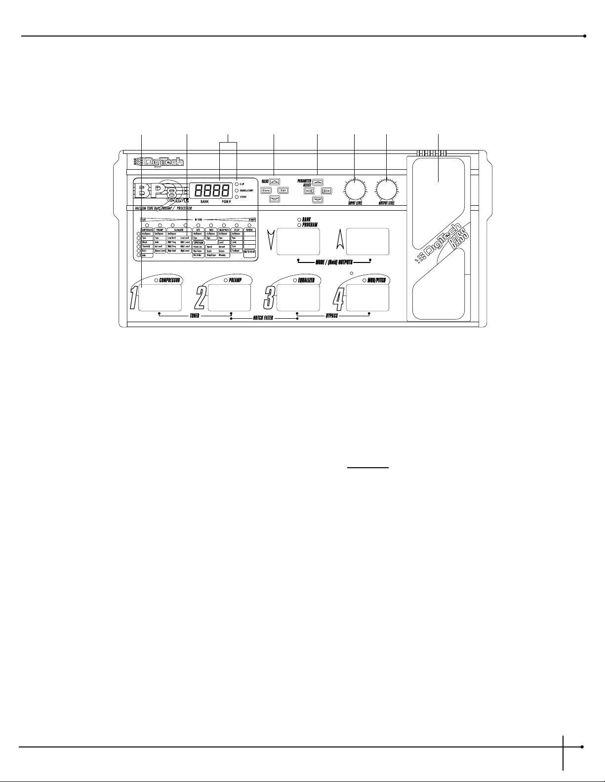
A Quick Tour of the BP-8 Valve
The Front Panel
1) Pedalboard - The BP-8 Valve’s pedalboard consists of six footswitches. The two mode footswitches to the right of the Parameter Matrix
allow you to change from Program mode to Bank mode by pressing the <UP> & <DOWN> footswitches simultaneously. When changing
modes, the appropriate LED will light to indicate whether you are in Program mode or Bank mode. In Program mode, the <UP> and
<DOWN> footswitches allow you to move through Programs, while the four main switches, labeled <1 - 4>, act as toggle On/Off
switches for Compressor, Preamp, EQ, and Mod/Pitch. In Bank mode, the <UP> and <DOWN> footswitches allow you to move through
Banks, while the <1-4> footswitches are used to select Programs. If footswitches <1> and <2> are pressed simultaneously, Tuner mode
will be activated. If footswitches <2> and <3> are pressed simultaneously, the Notch Filter
is selected for editing. If footswitches <3>
and <4> are pressed simultaneously, Bypass mode will be activated.
2) Parameter Matrix - The Parameter Matrix consists of a horizontal group of Effect LEDs and a vertical group of Parameter LEDs. The Effect
LEDs are: Compressor, Preamp, Equalizer, Noise Gate, Wah, Mod/Pitch, Delay and Reverb. This matrix shows you exactly what effects and
parameters are in use.
3) Display Window - The display window shows all current operating and programming information and is comprised of two parts: the
numeric LED displays and the Signal, Clip, and Store indicator LEDs. The first numeric LED in the display window indicates whether you
are in a User (U) or Factory Bank (F). The second and third numeric LEDs indicate the Bank number currently in use, and the fourth
indicates which Program number is currently in use. These numbers change as you scroll through the available Programs. The functions of
the Signal, Clip, and Store indicator LEDs are as follows:
• Signal/Comp - A green LED indicates signal is present in the BP-8 Valve. A yellow LED indicates the signal is being compressed by the
Compressor and can be adjusted by the Compressor’s Threshold parameter.
• Clip - Indicates analog clipping in the BP-8 Valve. Digital clipping can be detected when the third vertical LED from the top of the
Parameter Matrix flashes. Distortion may be heard in the output signal if either analog or digital clipping occurs. If analog clipping occurs,
BP-8 Valve
User Guide
Section -1 Introduction
3
24567 81
3
Page 10

reduce the Input Level using the Input Level knob. To reduce digital clipping, the Preamp on/off levels, EQ, and/or Effects levels should be
checked and adjusted accordingly. As always, let your ears be the judge.
• Store - Lights when a Parameter has been changed in a Program. (see page 9, under Store mode for further information on storing a
Program).
4) Value, Store and Edit Buttons - The Value <UP> and <DOWN> buttons allow you to scroll through the BP-8 Valve’s Programs, or
change Parameter values in Edit mode. The <STORE> button allows you to store an edited program in memory, or copy a program to
another User Program location for later use. The <EDIT> button enters Edit mode and allows you to edit the User and Factory programs.
5) Parameter Select Buttons -The <LEFT> and <RIGHT> Parameter Select buttons allow you to navigate the horizontal Effect LEDs of the
Parameter matrix. The <UP> and <DOWN> Parameter buttons allow you to navigate the vertical parameter LEDs of the Parameter matrix.
These keys are only active in Edit mode.
6) Input level - Controls the strength of the instrument signal into the BP-8 Valve.
7) Output Level - Controls the overall output level of the BP-8 Valve, as well as the overall level of the headphones.
8) Expression Pedal - This volume-type pedal allows real time control over Parameters in the BP-8 Valve.
Section 1 Introduction
BP-8 Valve
User Guide
4
Page 11

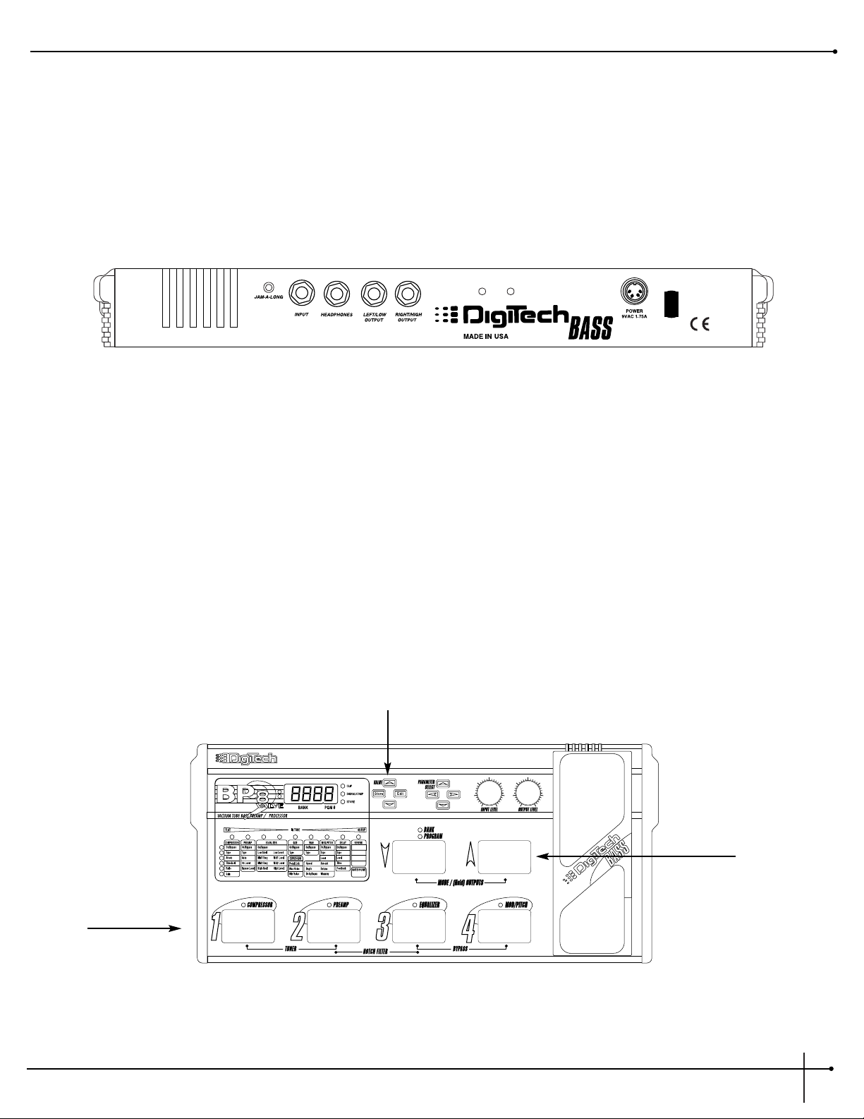
The Rear Panel
1) Jam-Along Jack- This is the Jam-Along jack connection of the BP-8 Valve. Connect the headphone output of CD or cassette player here
using an 1/8” stereo cable. Use the headphone volume control of the CD or cassette player to balance the level with that
of the BP8.
2) Input - This is the BP-8 Valve’s audio input. Plug your bass in here.
3) Headphone Output - 1/4” stereo plug for headphones. The headphone level is controlled by the main output
level knob.
4) Left/Low Output - This is the BP-8 Valve’s left main audio output in Stereo mode and the Low Frequency output in Hi/Low (biamp) mode.
5) Right/High Output - This is the BP-8 Valve’s right main audio output in Stereo mode and the High Frequency output in Hi/Low (biamp)
mode.
6) AC Line Input - This is the AC adapter receptacle. Use only the included PS 0920 power supply.
7) Power Cord Strain Relief - This strain relief is used to prevent the power supply from being disconnected from the power jack.
BP-8 Valve
User Guide
Section -1 Introduction
5
1
3
2
45 6
7
Page 12

Section-2 Setting Up
Making Connections
Your BP-8 Valve can be connected in several different ways to meet the requirements of specific applications. The following diagrams offer
some different ways your BP-8 Valve can be connected.
For those of you out there that feel that “bigger is better”, this set-up should work quite nicely for you. First plug your bass into the input of the
BP-8 Valve. Connect both BP-8 Valve outputs into the inputs of both of the amplifiers. Using a set-up such as this will let you produce bass
tones with lots of body. This is also a great set-up to produce lush and thick stereo effects.
BP-8 Valve into two Bass Amplifiers
The BP-8 Valve’s Preamp Section allows you to run direct to a mixing board. First, plug your bass into the Input of the BP-8 Valve. Next,
connect cables from both Left and Right Outputs into the Mixing board. Adjust the Output Level to match the sensitivity of your mixer. Be
careful as too much output level can distort the input stage of your mixer channels.
Running Direct into a Mixer
Section -2 Setting Up
BP-8 Valve
User Guide
6
Instrument Input
Left Output
Right Output
Instrument Input
Left Output
46
2
0
Aux 1
46
2
0
Aux 2
0
-1
+1
-2
-3
-4
-5
Pan
Mute
L / R
+10
+5
0
-5
-10
-20
-30
-°
1234
46
46
2
2
8
8
0
0
10
10
Aux 1
Aux 1
46
46
2
2
8
8
0
0
10
10
Aux 2
Aux 2
0
-1
-1
+1
-2
-2
+2
+2
-3
-3
+3
+3
-4
-4
+4
+4
-5
-5
+5
+5
Pan
Mute
Mute
L / R
L / R
+10
+10
+5
+5
0
0
-5
-5
-10
-10
-20
-20
-30
-30
-°
-°
Right Output
46
46
46
46
46
2
2
2
2
2
8
0
10
Aux 1
46
2
8
0
10
Aux 2
0
0
-1
+1
-2
+2
-3
+3
-4
+4
-5
+5
Pan
Pan
Mute
L / R
+10
+5
0
-5
-10
-20
-30
-°
8
8
8
8
8
0
0
0
0
10
10
10
10
10
Aux 1
Aux 1
Aux 1
Aux 1
46
46
46
46
2
2
2
2
8
8
8
8
8
0
0
0
0
10
10
10
10
10
Aux 2
Aux 2
Aux 2
Aux 2
0
0
0
0
-1
-1
-1
-1
+1
+1
+1
+1
+1
-2
-2
-2
-2
+2
+2
+2
+2
+2
-3
-3
-3
-3
+3
+3
+3
+3
+3
-4
-4
-4
-4
+4
+4
+4
+4
+4
-5
-5
-5
-5
+5
+5
+5
+5
+5
Pan
Pan
Pan
Pan
Mute
Mute
Mute
Mute
L / R
L / R
L / R
L / R
+10
+10
+10
+10
+5
+5
+5
+5
0
0
0
0
-5
-5
-5
-5
-10
-10
-10
-10
-20
-20
-20
-20
-30
-30
-30
-30
-°
-°
-°
-°
5
6
7
8
Page 13

If you choose to run the BP-8 into a Bi-Amp system. You are given the option of using the Hi-Lo output set up which allows you to set the
Cross-Over frequency at which the BP-8 will route the output frequencies to either the High or Low Outputs. The Procedure selecting this
output is as follows:
BP-8 Valve into a Bi-Amp System Using the Hi-Lo Outputs
To select the High-Low Bi-amping output of the BP-8, from Program mode press and hold the <MODE/(HOLD) OUTPUT> footswitches for 3
seconds until the display reads:
Outs
and then the currently selected output mode will be displayed. From the factory Ster (Stereo) will be selected. Now use the Value <UP>
and <DOWN> buttons to select High - Low Bi-amping and it will appear as follows:
HiLo
Now to select the Cross-Over frequency at which the BP-8 will route the output signal to either the High or Low outputs, press the parameter
<RIGHT> arrow button and the currently selected Cross-Over frequency will be displayed. Now use the Value <UP> and <DOWN> arrow
buttons to select the frequency. Range is from 80 to 500Hz. Once the frequency has been selected, press any foot switch to exit. This setting
will now be used with every program in the BP-8 and will be retained when the BP8 is turned off.
For more information about selecting Output, please see the Output Mode section on page 10.
BP-8 Valve
User Guide
Section -2 Setting Up
7
Instrument Input
Left/Low
Output
Right/High
Output
Page 14

Section 3 - Basic Operations
About the BP-8 Valve’s modes
The BP-8 Valve offers several different modes, allowing easy operation of the Effects and Parameters. The modes are as follows:
PROGRAM MODE
Program mode allows you to scroll through the BP8’s User and Factory Programs using the Value <UP> and <Down> buttons and the <UP>
and <DOWN> foot switches. Enter Program mode by pressing the <UP> and <DOWN> foot switches simultaneously until the Program LED
lights and the letter P appears briefly in the display. Foot switches <1-4> will act as on/off toggle switches for the specified effects in Program
mode.
BANK MODE
Bank mode is the factory default setting and allows you to scroll quickly through Factory and User Banks by using the <UP> and <DOWN>
foot switches. Enter Bank mode by pressing the <UP> and <DOWN> foot switches simultaneously until the Bank LED lights and a B appears
briefly in the display window. When you enter Bank mode, the Bank and Program numbers from the previous mode will be retained.
When the <UP> and <DOWN> footswitches are used in Bank mode, you will scroll through Banks only. When you change a Bank using this
method, the previous Program number is not displayed with the new Bank. The LEDs above foot switches <1-4> will begin flashing, indicating
that you can choose a Program in the selected Bank by pressing one of the four foot switches. Once a Program number has been selected, both
the Bank and Program numbers will be displayed.
EDIT MODE
Allows you to modify effect parameters in a Program. Enter Edit mode by pressing the <EDIT> button. The Display window now shows the
value of the parameter indicated by the LEDs in the Matrix. You can scroll through the Parameter matrix using the Parameter Select buttons.
The <UP> and <DOWN> buttons allow you to scroll through the vertical Parameter LEDs, while the <LEFT> and <RIGHT> buttons allow
you to scroll through the horizontal Effect LEDs. Follow the horizontal and vertical LEDs across the matrix to the point where they intersect.
This will be the parameter you are about to edit.
Section -3 Basic Operations
BP-8 Valve
User Guide
8
Page 15

After selecting a Parameter, you can scroll through its values with the Value <UP> and <DOWN> buttons. When changing Parameter values,
a decimal point will flash in the display when the value is not the stored value for the program. The Store LED will light at this time as well. If
you return to the original value, the decimal point will stop flashing and the Store LED will go off. If you exit Edit mode after changing the
Parameters and then return to Edit mode, the last viewed parameter will be displayed.
STORE/COPY MODE
Once you have modified the Parameters and Effects, you can store them to a User Program location. When you change an Effect or Parameter
in a Program, the Store LED will light, indicating that you have changed a Parameter and need to store the changes. Press the <STORE>
button once and the first seven segment LED in the Display window will flash U. Select the User Bank and Program location you want to store
your changes to using the Value <UP> and <DOWN>buttons, then press the <STORE> button again to save the changes. Use the same
procedure, less the editing, to copy a program to a new User location.
BYPASS MODE
Bypass mode globally bypasses the compressor, preamp and all effects. Enter this mode by pressing footswitches <3 & 4> simultaneously.
BYP will appear in the display window to indicate you are in Bypass mode. Exit this mode by pressing any of the footswitches. When you exit
this mode, the BP-8 Valve will default to the last mode you used. Bypass does not affect the Notch Filter nor the Hi/Low crossover frequency
settings.
TUNER MODE
Allows you to tune your bass. Enter Tuner mode by pressing footswitches <1 & 2> simultaneously. tune will appear briefly in the display
window followed by
---
to indicate that you are in Tuner mode. To begin tuning play a note on your bass (a harmonic at the 12th fret will
work best). The display window will show the note being played and the horizontal Parameter Matrix LEDs just under the tuning bar will light.
Once the green LED directly under the IN TUNE of the tuning bar is lit, the note will be in tune. If the note is not in tune, 1 or 2 of the LEDs
left or right of the IN TUNE LED will be lit. If they are to the left, the note is flat and should be tuned up. If the LEDs are to the right, the note
is sharp and should tuned down. You can change your tuning preference by using the value <UP> and <DOWN> buttons. The default
factory setting is : A=440 Hz. The tuning reference control ranges from 427 Hz to 453 Hz, which is the equivalent of ± 50 cents (1/2
semitone) in either direction form 440 Hz.
When you scroll down from 427 Hz, you will also find alternate dropped tunings. Alternate tunings are A = Ab (415), A = G (392), and A =
Gb (370). The display window will briefly flash the currently selected tuning preference.
Exit this mode by pressing any of the footswitches. When you exit this mode, the BP-8 Valve will default to the last mode you used.
BP-8 Valve
User Guide
Section - 3 Basic Operations
9
Page 16

NOTCH FILTER
The BP-8 also offers an adjustable notch filter which helps reduce annoying low frequency room resonance from one venue to the next. The
procedure for editing the Notch filter is as follows:
1. From Program mode, press and hold the <2> and <3> footswitches.
2. ntch will briefly appear in the display followed by the currently selected notch filter frequency and the LEDs above the <2> and
<3> footswitches will light, indicating that you are in Notch Filter edit mode .
3. Move the expression pedal or use the Value <UP> and <DOWN> until the desired Notch frequency is displayed. Notch filter range is
from from Off to 500Hz.
4. Once the desired frequency has been selected, press any foot switch to exit this mode. This Notch filter frequency is applied globally to all
programs and will remain in memory until edited again or until the BP8’s power is disconnected.
OUTPUT MODES
The BP-8 offers 3 output modes to select from: Dual (Mono) mode, Stereo mode, and Hi/Lo (Biamp) mode. The procedure for changing
the Output modes is as follows:
1. From Program mode, press and hold the <UP> and <DOWN> footswitches for 3 seconds. The display will then show the current
output mode.
2. Use the Value <UP> and <DOWN> buttons to select the desired Output mode. Dual mode is a mono output mode that sends the
same program material to both outputs. Stereo mode splits any effects with stereo imaging to the left and right outputs. Hi/Lo (biamp)
mode sends high frequency material out the Right output and Low frequency material out the Left output. If Hi/Lo mode is selected, you
can adjust the crossover frequency by pressing the <Right> parameter button and by using the Value <UP> and <DOWN> buttons.
Material above the selected crossover frequency will be sent out the Right output and material below the the crossover frequency will be
sent out the Left output.
NOTE: If headphones are plugged into the BP8, the output mode defaults to Stereo. Unplugging the headphones will return the Output
mode to it’s previously selected mode.
Section - 3 Basic Operations
BP-8 Valve
User Guide
10
Page 17

SECTION 4 - EFFECTS AND PARAMETERS
About the Parameter Matrix
The Parameter Matrix displays all the Effects and Parameters you can find in the BP-8 Valve. The Parameters are arranged in rows and columns.
Use the Parameter Select buttons to select the parameter to be edited. The Effects and their Parameters are as follows:
The compressor on the BP8 is unique in its ability to bypass high frequencies around the compressor to retain a natural tone while limiting
the maximum power in the signal and increasing sustain. The result is a sound that is smooth and full with good transients that can be heard
in the mix without overpowering it.
On / Bypass Turns the Compressor on or off.
Type Four types are available. Type 1 is closest to normal compressor operation with all frequencies being
compressed. Types 2-4 send more high frequencies around the compressor. Each has its own sound;
experiment to see which ones work for you in which situations.
Attack Determines the attack time of the compression action. 1 is the fastest, 4 the slowest. Generally fast
attack times are useful with aggressive playing, slower times with more sustained notes. Too fast an
attack time can cause slight distortion on long sustained tails of notes so experiment to get the right
setting for your application.
Threshold Determines the signal strength which activates the compressor. This control is calibrated in dB below
full output. As the threshold becomes more negative, the lower the signal strength needs to be in order
for it to be compressed. The SIGNAL/COMP light turns yellow when your signal is higher than the
compression threshold (which means your signal is being compressed).
Ratio Determines the amount of compression after you exceed the threshold. For instance a ratio of 2.5-1
means that for every 2.5 dB your signal exceeds the threshold, your output will only increase 1 dB.
Ratios are as follows: 1.5:1 through 25:1.
Gain This parameter controls the overall amount of output gain in the Compressor effect. Range is from 0-62.
Use this parameter to balance the levels between Compressor on and Compressor off.
Compressor
Parameters
Displayed Values
On/Bypass On-byps
Type 1-4
Attack 1-4
Threshold 0...-62
Ratio 1.5-1...25-1
Gain 0-62
BP-8 Valve
User Guide
Section - 4 Effects and Parameters
11
Page 18

The Preamp section of the BP-8 Valve has 13 extremely flexible voicings to choose from. Some emulate preamps found in some of today’s
popular bass amplifiers while others can be used for distortion tones found in some of today’s popular music.
On / Bypass Turns the Preamp on or off.
Type Selects the Preamp type used. CLn1=Warm Tube, CLn2=Warm Bright Tube, CLn3=Punchy,
CLn4=Punchy Bright, CLn5=Classic Tube, CLn6=Classic Bright, CLn7=Backbeat,
CLn8=High Definition, CLn9=Full Five String, CLn0=Modern Five String. The BP8 also has
cutting edge distortion preamp settings for some of today’s modern rock bass sounds. HSuS=Dark
Distortion, SAt=Saturated Tube Distortion, Od=Overdrive Distortion
Gain Controls the amount of distortion produced by the BP-8 Valve. High settings produce greater gain and
drive, while low settings offer better dynamic control of tone. Ranges from 1-100.
On Level Sets the output level while the Preamp is ON. Ranges from 0-100.
Bypass Level Sets the output level while the Preamp is Bypassed. Ranges from 0-100.
Preamp
Parameters
Displayed Values
On/Bypass On-byp
Gain 0-100
Type CLn1-CLn0, HSus, Sat, Odr
On Level 0-100
Bypass Level 0-100
Section - 4 Effects and Parameters
BP-8 Valve
User Guide
12
Page 19

The BP-8 Valve offers a four band equalizer. Each frequency is adjustable along with its gain (boost or cut).
On / Bypass Turns the EQ on or off.
Low/High Shelf
Mid 1/Mid 2 Freq Allows you to select the shelving or center frequency of these bands.
Level Allows you to boost and cut the frequency. Ranges are from -15dB to 15dB.
The BP-8 Valve’s Noise gate offers you a professional quality digital noise reduction effect.
On / Bypass Turns the Gate on or off.
Type Selects one of 10 different noise gate types. There are 2 noise gate thresholds, Low and High, to choose
from, each with 5 attack settings. Choose a Low threshold if noise is not a problem and a High
threshold if there is a noise problem. The longer attack settings provide a volume swell effect after
playing a note, each with a different time constant. The Attack settings are: Attack 1=0ms (milliseconds), Attack 2=100ms, Attack 3=250ms, Attack 4=500ms, and Attack 5=1.2 seconds.
Noise Gate
Parameters
Displayed Values
On/Bypass On-byp
Type Lo 1...Hi 5
Equalizer
Parameters
Displayed Values
On/Bypass
Low Shelf
Low Level
On-Byp
31...500
-15...0...15
Mid 1 Freq
Mid 1 Level
80...2000
250...4000
-15...0...15
-15...0...15
-15...0...15
Mid 2 Freq
Mid 2 Level
High Shelf 1000...1º00
High Level
BP-8 Valve
User Guide
Section - 4 Effects and Parameters
13
Page 20

The BP-8 Valve’s Expression Pedal allows you to control various parameters in real time during performance.
Pedal Link This selects the parameter that will be controlled by the Expression Pedal in the current program.
Max Value Sets the maximum value that the parameter assigned to the Expression pedal will reach when the Pedal is
in the forward position (toe down). Range varies according to the parameter selected.
Min Value Sets the minimum value that the parameter assigned to the Expression Pedal will reach when the Pedal is
in the back position (toe up). Range varies according to the parameter selected.
To Link the Expression Pedal to a parameter, follow these steps:
1. Press the <Edit> button.
2. Use the <Right> Parameter button until the LED above the Gate column is lit
3. Use the <DOWN> Parameter button until the 4th LED down on the vertical row is lit.
4. Use the Value <UP> and <DOWN> arrows to select the parameter you want linked to the pedal in
the display.
5. Set the Min and Max values between which you want the parameter to vary.
The BP-8 Valve offers a 3 types of wah which can be used with or without Distortion for that classic Wah-Wah sound.*
On / Off Turns the Module on and off.
Type Selects the type of Wah. 1=Classic Wah, 2=Envelope Wah, and 3=Bass Wah.
* The Wah can be linked to the Expression Pedal. See instructions in the previous section.
Wah
Parameters
Displayed Values
On/Bypass On-byp
Type
1...3
Expression Pedal
Parameters
Displayed Values
Pedal Link
OFF Spd
dept LI
Max Value Parameter dependent
(Wah) (Speed)
detn (Detune Amount ) bend (Whammy)
dly(Delay Level) fb (Delay Feedback)
Pre (Pre-effects Output Levl)
rbl (Reverb level)
(Depth) (Mod/Pch Level)
Min Value Parameter dependent
SENS
(Sensitivity)
Ah
post
(Post-effect Output Level)
Section - 4 Effects and Parameters
BP-8 Valve
User Guide
14
Page 21

Mod/Pitch Effects
The Mod/Pitch effect section in the BP-8 Valve allows you to select effects such as: Chorus, Flanger, Phaser, Tremolo, Panner, Pitch Shift,
Whammy™ (Bend), Fretless, Octabass, and Envelope Filter. The Parameters of these effects are adjusted in this module.
On / Bypass Turns the Module on or off.
Type Allows you to select a specific type of modulation/pitch effect. The Types are: Chorus, Flanger, Phaser,
Tremolo, Panner, Pitch Shift, Whammy™ (Bend), Fretless, Octabass, and Envelope Filter.
Level Controls the overall mix level of the mod or pitch shifting effect. Ranges from 0 to 100.
The BP-8 Valve offers a chorus that is unique in both character and sound. This dual chorus offers exceptionally rich chorusing using multiple
voices with different phasing characteristics. Chorus Parameters are as follows:
Speed Controls the speed of the chorus sweep. Ranges from 0 to 100.
Depth This Parameter sets the sweep depth (intensity) of the chorus. Ranges from 0 to 100.
Delay Sets the amount of delay present in the chorus effect. Ranges from 0 to 100.
The BP-8 Valve also offers exceptionally rich studio-quiet flanging. Flange Parameters are as follows:
Speed Controls the speed of the flange sweep. Ranges from 0 to 100.
Depth Sets the depth amount and delay present in the flange effect. Ranges from 1 to 16.
Regeneration This Parameter sets the amount of regeneration which is perceived as the sweep depth (intensity) of the
flange. Variable from -99 to 99.
Flanger FLan
Values Displayed Values
Speed 0...100
Depth 1...16
Regeneration
-99...0...99
Chorus Chor
Values Displayed Values
Speed 0...100
Depth 0...100
Delay 0...100
BP-8 Valve
User Guide
Section - 4 Effects and Parameters
15
Page 22

The BP-8 Valve’s classic adjustable phase shifting effect is reminiscent of mid-70’s keyboard and bass sounds.
Speed Controls the speed of the phase sweep. Ranges from 0 to 100
Depth Sets the sweep depth (intensity) of the phaser. Ranges from 0 to 100.
Regeneration Controls the amount of phased sound fed back to the input of the Module. High regeneration settings
produce dramatic and interesting unnatural sounds. Ranges from 0 to 99.
Tremolo was one of the first real effects and appeared mostly on guitar amplifiers. The BP-8 Valve breathes new life into this classic effect by
offering it to the bassist. It provides totally transparent volume modulation.
Speed Controls the tremolo speed (speed of modulation). Ranges from 0 to 100.
Depth Adjusts the intensity of the tremolo effect. Ranges from 0 to 100.
An auto panner is a modern relative of the tremolo that modulates the sound from left to right at a given rate. Parameters are as follows:
Speed Controls the panning speed (speed of modulation). Ranges from 0 to 100
Depth Adjusts the intensity of the panning effect. Ranges from 0 to 100.
Auto Panner PAn
Values Displayed Values
Speed 0...100
Depth 0...100
Tremolo trE
Values Displayed Values
Speed 0...100
Depth 0...100
Phaser PHAs
Values Displayed Values
Speed 0...100
Depth 0...100
Regeneration 0...99
Section - 4 Effects and Parameters
BP-8 Valve
User Guide
16
Page 23

The BP-8 Valve’s Pitch Shifting effect gives you a shifted signal from 0 to 24 semi-tones above or below the pitch of the input signal.
Amount Sets the interval between the original note and the pitch shifted note. Variable from -24 to 24
Detune Determines the amount of detuning applied to the shifted note. Variable from -99 to 99.
The BP-8 Valve’s Whammy™ pitch bending effect allows you to smoothly shift between two preset pitch intervals using the Expression
Pedal. *
Amount Selects the function of the Whammy™ Module. There are 16 functions available in regular Whammy
Modules. They are as follows:
Whammy Harmony (Dry Signal Added)
Octave Up=OcUP Octave Up/Octave Down=OuOd
2nd Up=2ndU Octave Down/4th Down=Ou4d
2nd Down=2ndd 4th Down/3rd Up=4d3u
4th Down=4thd 4th Up/5th Up=4u5u
Octave Down=OcUP 5th Up/6th Up=5u6u
5th Up/Octave Up=5uOu
Detune=detn
Whammy The Whammy Parameter reflects the current setting of the Whammy™ effect. As this parameter is
modified, the pitch of the original note will change in intervals according to the setting of the Amount
parameter. Ranges from 0 to 100.
* To link the Whammy function to the Expression Pedal, see instructions on page 14.
Whammy bEnd
Values Displayed Values
Amount OcUp ... detn
Whammy 0 ... 100
Pitch Shifter Ptch
Values Displayed Values
Amount -24...0...24
Detune -99...0...99
BP-8 Valve
User Guide
Section - 4 Effects and Parameters
17
Page 24

The BP-8 also provides you with a Envelope Filter effect module that allows you to have the Wah type effect without doing the leg-work.*
Speed (Sensitivity) The Speed parameter controls the how fast the Envelope filter opens and closes. Range is from 1 to 100.
Depth (Type) Selects one of 7 Envelope Filter types. 1=Big Envelope, 2=Wah, 3=Electronic Drum, 4=Ow Filter,
5=Extreme, 6=, 7=Mid Wah
Dly/Regen (Dry Level) Selects the amount of dry signal to be added with the Envelope Filter signal. Range is 0-100.
*The Wah effect is not available when the Envelope Filter is selected as the Mod type.
Another unique feature to the BP-8 is the Fretless Bass Simulator which is ideal for creating a fretless sound as well as an emulation of a
“Bowed” bass sound.*
Amount (Time) Controls how fast the Fretless effect swells. Range is from 1 to 10.
Depth Controls how far the Fretless effect progress. Higher settings sound more nasal or “bowed”. Range is
from 0 to 100.
Dly/Regen (Sensitivity) Controls the sensitivity of the Fretless effect. Higher settings combined with the Depth parameter will
give different qualities to the sound.
*The Wah effect is not available when the Fretless Simulator is selected as the Mod type.
Amount 1...10
Regen (Sensitivity)
0...100
Fretless Fret
Values Displayed Values
Amount (Time) 1...10
Depth
0...100
Regen (Dry Level)
1...100
Envelope Filter Eftr
Values Displayed Values
Speed (Sensitivity) 1...100
Depth (Type)
1...7
Section - 4 Effects and Parameters
BP-8 Valve
User Guide
18
Page 25

For those of you that desire to hit those “Jazzy lows”, the BP-8 has incorporated an Octa-Bass effect module.
Level The level parameter controls the how much of the Octa-Bass effect is heard Range is from 1 to 10.
The Delay effect section of the BP-8 includes the world famous studio-caliber Digitech 1 and 2 Tap delays.
On / Off Turns the Effect on and off.
Type Determines the type of delay. Types include 1 and 2 Tap
Level Controls the level of the delay in both Delay1 and Delay 2. Ranges from 0 to 100.
Time The available delay time ranges are 0 (no delay) to 3.5 seconds. The displayed value is in milliseconds.
Feedback Controls the amount of delayed signal that is fed back into the input of the Delay. Higher settings result
in more delay repeats. Ranges from 0 to 99 and Repeat Hold.
Delay (1 and 2 Tap)
Parameters
Displayed Values
On/Off
Type
Level
On-B yp
1tap - 2tap
0...100
Time 0...3500
Feedback 0...99 r Hl d
Octa Bass Octb
Values Displayed Values
Level 0...100
BP-8 Valve
User Guide
Section - 4 Effects and Parameters
19
Page 26

Ambience, or reverberation, is produced when sound energy is reflected off room surfaces and objects. Using reverb in recorded program
material gives the listener a sense that the material is being performed in an actual room or hall. It is this similarity to actual acoustic spaces
that makes reverberation a useful tool in recorded music. Reverb Parameters and their functions are as follows:
On / Bypass Turns the Reverb effect on or off.
Type Allows you to choose your ambience or setting you want to use. There are nine available type settings:
CLub=Club Garg=Garage
pLat=Plate HALL=Hall
Chur=Church ArEn=Arena
bAth=Bathroom Stud=Studio
SPrg=Spring
Level Controls the amount of Reverb signal to be mixed in with the dry signal. Ranges from 0 to 100.
Decay Time The amount of time it takes for the Reverb to fade to inaudibility. Ranges from 1 to 10.
The BP-8 Valve’s Master Volume controls the overall volume level of the selected program. The level can be controlled with the Expression
pedal for balancing levels in real-time during live performance. *
Level Controls the overall volume level of the program. Variable from 0 to 100.
* To link the Master Volume function to the Expression Pedal, see instructions on page 14.
Master Volume
Parameter
Displayed Value
Level
0-100
Reverb
Parameters
Displayed Values
On/Bypass
Type
Level
On-byp
CLub...SPr g
0...100
Decay Time 1...10
Section - 4 Effects and Parameters
BP-8 Valve
User Guide
20
Page 27

Section 5 - Appendix
Reinitializing the BP-8 Valve
This option allows you to restore the contents of the BP-8 Valve’s memory to the original factory condition and calibrate the expression pedal.
WARNING: Performing this function will destroy all user-programmed data. All such data will be lost forever!
To restore the factory Programs and calibrate the expression pedal, the procedure is as follows:
1. Plug in the BP-8 Valve while holding down the Parameter Select <UP> button.
2. When rSt appears in the display window, release the Parameter <UP> button and press the Value <UP> button. The BP-8 will reset
to factory condition.
3. The display will now prompt you to re-calibrate the expression pedal by reading: PEDL CAL
4. When the display reads: toe dn , rock the pedal forward and press any one of the flashing footswitches.
5. When the display reads: toe up , rock the pedal back and press any one of the flashing footswitches. The expression pedal will now
be calibrated and the BP-8 will return to program mode.
Re-calibrating the Expression Pedal
If the Expression Pedal calibration should fail, you can re-calibrate it by disconnecting the power, press and hold the parameter select
<DOWN> button and re-apply power. Release the button and repeat steps 3-5 as shown in the “Re-initializing the BP-8 “ section above.
BP-8 Valve
User Guide
Section - 5 Appendix
21
Page 28

Specifications
A/D Converter: 20 bit 128x Oversampled
D/A Converter: 20 bit 128x Oversampled
Sampling Frequency: 39 kHz
DSP Section:
Architecture: Static-Dynamic Instruction Set Computer (S-DISC II™)
Digital Signal Path Width: 24 bits (144.5 dB)
Internal Data Path Width: 48 bits (289 dB)
Dynamic Delay Memory: 256k x 24 bits (3.5 seconds)
Static Delay Memory: 256 24-bit registers (6.55 milliseconds)
Data ALU Processing: 10.0 MIPS
Address ALU Processing: 15.0 MIPS
Multiplier Size: 24 bits x 24 bits
Tube Type:
(1) 12AX7
Plate Voltage: 100volts
Input Section:
Connector: 1/4” Unbalanced TRS
Nominal Level: -8 dBu
Maximum Level: +10 dBu
Impedance: 470 kohms
Output Section:
Connector: 1/4” TRS
Nominal Level: +4 dBu
Maximum Level: +18 dBu
Impedance: 50 ohms
General:
Frequency Response: 20 Hz. - 16 kHz
S/N ratio: Greater than 95 dB; ref = max signal, 22 kHz measurement bandwidth
Total Harmonic Distortion: Less than 0.04% (1 kHz.)
Memory Capacity: Factory: 40 Programs User: 40 Programs
Power Requirements:
US and Canada: 120 V AC, 60 Hz
Japan: 100 V AC, 50/60 Hz
Europe: 230 V AC, 50 Hz
UK: 240 V AC, 50 Hz
Power Consumption: 16 watts
Dimensions: Length 18” Width 8.75” Height 2.75”
Power Supply: PS-0920
Section - 5 Appendix
BP-8 Valve
User Guide
22
Page 29

Preset List
The following is a list of all the factory Programs in the BP-8 Valve.
Bank 1
F11 Super Punch
F12 Crisp Clean Octabass
F13 Synth Bass
F14 Pseudo Bow
Bank 2
F21 Extreme Envelope
F22 Delayed Phase
F23 Pedal 5 String
F24 Vibro Crunch
Bank 3
F31 Exit 13
F32 Bass Synth
F33 Pick Flange
F34 SVT Grit
Bank 4
F41 Chorused Clean
F42 Compressed Slap
F43 Octo Cavern
F44 Growl Wah
Bank 5
F51 Fat Sustain
F52 Beefy AutoWah
F53 Fat Pick
F54 Mid Scoop
Bank 6
F61 Distorted 5ths
F62 Space Slap
F63 Facination
F64 Wah Baby
Bank 7
F71 Grindy Tremolo
F72 Octo Solo
F73 Sound on Sound
F74 Industrial Envelope
Bank 8
F81 Mid Punch
F82 Drippy
F83 Reggae Mon
F84 Pedal Fretless
Bank 9
F91 Pedal Glissando
F92 Whammy Up
F93 Dirty Tremolo
F94 Octabass
Bank 10
F10-1 Super Envelope
F10-2 Chewy Octave
F10-3 Octave Whammy Down
F10-4 Flange Thing
BP-8 Valve
User Guide
Section - 5 Appendix
23
Page 30

8760 South Sandy Parkway
Sandy, Utah, 84070
Telephone 801.566.8800
FAX 801.566.7005
International Distribution:
3 Overlook Drive, Unit 4
Amherst, New Hampshire 03031 U.S.A.
FAX 603.672.4246
DigiTech™, Whammy™, and S-DISC™II are registered trademarks
of the Harman Music Group Incorporated
Copyright © 1998
the Harman Music Group Incorporated
Printed In U.S.A. 8/98
Manufactured in the U.S.A.
BP-8 Valve 18-2268-A
Please Visit Digitech on the World Wide Web at:
http://www.digitech.com
 Loading...