

Page 1

Analog WDR PTZ
In/Outdoor Camera
User’s Manual
Before installing and using the camera, please read this manual carefully.
Be sure to keep it handy for future reference.
Ver. 1.0 / 2012.06
Page 2

Safety Information
CAUTION
RISK OF ELECTRIC SHOCK.
DO NOT OPEN.
CAUTION
:
TO REDUCE THE RISK OF ELECTRIC SHOCK, DO NOT REMOVE COVER (OR BACK) NO USER SERVICEABLE
PARTS INSIDE. REFER SERVICING TO QUALIFIED SERVICE PERSONNEL.
Warning Precaution
This symbol indicates that dangerous voltage
consisting a risk of electric shock is present within
this unit.
WARNING
To prevent damage which may result in fire or electric shock
hazard, do not expose this appliance to rain or moisture.
WARNING
1.
Be sure to use only the standard adapter that is specified in
the specification sheet. Using any other adapter could cause
fire, electrical shock, or damage to the product.
2.
Incorrectly connecting the power supply or replacing battery
may cause explosion, fire, electric shock, or damage to the
product.
3.
Do not connect multiple cameras to a single adapter.
Exceeding the capacity may cause excessive heat generation
or fire.
4.
Securely plug the power cord into the power receptacle.
Insecure connection may cause fire.
5.
When installing the camera, fasten it securely and firmly.
A falling camera may cause personal injury.
6.
Do not place conductive objects (e.g. screw drivers, coins,
metal items, etc.) or containers filled with water on top of
the camera. Doing so may cause personal injury due to fire,
electric shock, or falling objects.
7.
Do not install the unit in humid, dusty, or sooty locations.
Doing so may cause fire or electric shock.
8.
If any unusual smells or smoke come from the unit, stop
using the product. Immediately disconnect the power sorce
and contact the service center. Continued use in such a
condition may cause fire or electric shock.
9.
If this product fails to operate normally, contact the nearest
service center. Never disassemble or modify this product in
any way.
10.
When cleaning, do not spray water directly onto parts of the
product. Doing so may cause fire or electric shock.
Precaution
Operating
• Before using, make sure power supply and all other parts are
properly connected.
is observed, stop using the camera immediately and contact
Handling
• Do not disassemble or tamper with parts inside the camera.
this can damage the camera.
dust can ruin the quality of the camera image.
Installation and Storage
exceeding the allowed range.
elds and electric signals.
to strong vibrations.
This exclamation point symbol is intended to alert the
user to the presence of important operating and
maintenance (servicing) instructions in the literature
accompanying the appliance.
• While operating, if any abnormal condition or malfunction
your dealer.
• Do not drop the camera or subject it to shock or vibration as
• Clean the clear dome cover with extra care. Scratches and
• Do not install the camera in areas of extreme temperature,
• Avoid installing in humid or dusty environments.
• Avoid installing in places where radiation is present.
• Avoid installing in places where there are strong magnetic
• Avoid installing in places where the camera would be subject
• Never expose the camera to rain or water.
2
Page 3

Important Safety Instructions
1. Read these instructions. - All these safety and operating instructions should be read before the product is
installed or operated.
2. Keep these instructions. - The safety, operating and use instructions should be retained for future reference.
3. Heed all warnings. - All warnings on the product and in the operating instructions should be adhered to.
4. Follow all instructions. - All operating and use instructions should be followed.
5. Do not use this device near water. - For example: near a bath tub, wash bowl, kitchen sink, laundry tub, in a wet
basement; near a swimming pool; etc.
6. Clean only with dry cloth. - Unplug this product from the wall outlet before cleaning. Do not use liquid cleaners.
7. Do not block any ventilation openings. Install in accordance with the manufacturer’s instructions. - Slots and
openings in the cabinet are provided for ventilation, to ensure reliable operation of the product, and to protect it
from over-heating. The openings should never be blocked by placing the product on bed, sofa, rug or other similar
surface. This product should not be placed in a built-in installation such as a bookcase or rack unless proper
ventilation is provided and the manufacturer’s unstructions have been adhere to.
8. Do not install near any heat sources such as radiators, heat registers, or other apparatus (including ampliers)
that produce heat.
9. Do not defeat the safety purpose of the polarized or grounding-type plug. A polarized plug has two blades with
one wider than the other. A grounding type plug has two blades and a third grounding prong. The wide blade
or the third prong are provided for your safety. If the provided plug does not t into your outlet, consult an
electrician for replacement of the obsolete outlet.
10. Protect the power cord from being walked on or pinched particularly at plugs, convenience receptacles, and
the point where they exit from the apparatus.
11. Only use attachments/accessories specied by the manufacturer.
12. Use only with cart, stand, tripod, bracket, or table specied by the
manufacturer, or sold with the apparatus. When a cart is used, use
caution when moving the cart/apparatus combination to avoid
injury from tip-over.
13. Unplug this apparatus during lightning storms or when unused for long periods of time.
14. Refer all servicing to qualied service personnel. Servicing is required when the apparatus has been damaged
in any way, such as power supply cord or plug is damaged, liquid has been spilled or objects have fallen into the
apparatus, the apparatus has been exposed to rain or moisture, does not operate normally, or has been
dropped.
3
Page 4

Disposal of Old Appliances
1. When this crossed-out wheel bin symbol is attached to a product it means the product is covered by
the European Directive 2002/96/EC.
2. All electrical and electronic products should be disposed of separately form the municipal waste
stream stream in accordance to laws designated by the government or the local authorities.
3. The correct disposal of your old appliance will help prevent potential negative consequences for
the environment and human health.
4. For more detailed information about disposal of your old appliance, please contact your city oce,
waste disposal service or the shop where you purchased the product.
This equipment has been tested and found to comply with the limits for a Class A digital device, pursuant to part 15 of the FCC Rules.
These limits are designed to provide reasonable protection against harmful interference when the equipment is operated in a commercial environment.
This equipment generates, uses, and can radiate radio frequency energy and, if not installed and used in accordance with the instruction manual, may cause
harmful interference to radio communications. Operation of this equipment in a residential area is likely to cause harmful interference in which case the user
will be required to correct the interferenece at his own expense.
4
Page 5

Table of Content
INTRODUCTION
INSTALLATION
OSD MENU
2
Safety Information
3
Important Safety Instructions
5
Table of Contents
6
Features
7
Product & Accessories
8
Parts& Description
9
Camera ID Setup
10
Teminal Block Connections
11
Surface Mount Installation
12
Accessories Installation
17
First Time Booting Up
18
Check Points Before Operation
19
Special Functions
20
OSD Information
SPECIFICATIONS
21
General Rules of Menu Operation
22
OSD - ROOT MENU & SYSTEM INFORMATION
23
OSD - DISPLAY SETUP
24
OSD - MOTION SETUP & PARKING ACTION
25
OSD - MOTION SETUP & ALARM INPUT
26
OSD - FUNCTION SETUP > PRESET SETUP
28
OSD - FUNCTION SETUP > SCAN SETUP
29
OSD - FUNCTION SETUP > PATTERN SETUP
30
OSD - FUNCTION SETUP > GROUP SETUP
32
OSD - FUNCTION SETUP > SCHEDULE SETUP
34
OSD - CAMERA SETUP > WHITE BALANCE SETUP
35
OSD - CAMERA SETUP > AUTO EXPOSURE SETUP
36
OSD - CAMERA SETUP > SPECIAL
37
OSD - SYSTEM SETUP
40
OSD - SYSTEM INITIALIZE
41
Dimension
44
Specification
APPENDIX
45
Troubleshooting
46
Warranty Information & Limits and Exclusions
47
Camera IDs
53
Reserved PResets
54
Using a USB mouse to control the Camera’s OSD Menu
59
Using Joystick Contrller to control the camera’s OSD menu
5
Page 6

Features
CAMERA SPECIFICATIONS
• 1/4” Sony Super HAD II (Double Scan) CCD
•
Zoom Magnification: ×12 Optical, ×32 Digital Zoom
• Wide Dynamic Range
• Day & Night Function: ICR (IR Cut filter Removal)
• Various Focus Mode: Auto Focus/Manual Focus/
Semi-Auto Focus
• Independent or Global Camera Settings for Each
Preset Location
POWERFUL PAN/TILT FUNCTIONS
• Maximum 360°/SEC High Speed Pan/Tilt Motion
• Vector Drive Technology: Pan/Tilt Motions are
accomplished in the shortest path. As a result,
time to target view is reduced dramatically and
the video on the monitor is very natural to watch.
• Ultra low speed (0.05°/SEC) enables operator to
locate camera to desired target view with accuracy
and ease.
• Zoom-Proportional Pan/Tilt speed helps operator
to move the camera easily.
PRESET, PATTERN, SCAN, GROUP, PRIVACY
ZONE, SCHEDULE, AND MORE...
• Maximum 127 presets are assignable. Each of
them have independent characteristics, such as
white balance, auto exposure, label, alarm
input/output, etc.
• Maximum 8 set of scans can be stored. This
enables user to move camera repetitively between
two preset positions with designated speed.
• Maximum 4 patterns can be recorded and played
back. This enables the camera to follow any
trajectory operated by the joystick as closely as
possible.
• Maximum 8 set of group actions can be stored.
This enables the camera to move repetitively
between dierent combination of preset, pattern,
or scan. A group is composed of maximum 20
entities of preset, pattern, or scan.
•
Maximum 8 privacy zones can be set up to protect
privacy of other people.
• 7 rules of schedule can be assigned by day and
time. Appropriate actions (such as home, preset,
scan, pattern, and group) can be defined for each
rule. Also, it is possible to use weekday and all days
to simplify the rule.
PTZ (PAN/TILT/ZOOM) CONTROL
• With RS485 communication, a maximum of 255
cameras can be controlled at the same time.
• Auto, Pelco-D, Pelco-P, Samsung, Panasonic, Kalatel,
AD(American Dynamics) protocol can be selected
as a control protocol in the current version of
firmware.
OSD(ON-SCREEN DISPLAY) MENU
• OSD Menu is provided to display the status of
camera and to configure the functions interactively.
•
Camera ID, Pan/Tilt/Zoom/Direction
Output, Date/Time, Current Temperature, and
Preset are displayed on screen.
• Each display item can be turned on or off
independently.
, Alarm Input/
ALARM I/O FUNCTIONS
• 2 Alarm sensor inputs and 1 relay output are
available.
• To reject external electric noise and shock perfectly,
alarm sensor input is decoupled with photo coupler.
• The signal range of sensor input is from DC 5.0 to
12.0 Volts to adopt various applications.
• If an external sensor is activated, camera can be set
to move to the corresponding preset position.
•
Relay outputs can be assigned to work with a certain
Preset.
RESERVED PRESETS FOR SPECIAL PURPOSE
• Most of camera settings are directly changed by
calling reserved presets, not entering into OSD
Menu. For more information, refer to “Reserved
Presets”(page 18) of this manual.
6
Page 7

Introduction -
Product & Accessories
Verify the following items are included in the package.
Main Body + Surface Mount Bracket
Accessories (Required)
Screw & Plastic Anchor-4pcs
Rubber Gasket
9P Terminal Block
Template Sheet
Torx Wrench
Manual CD
Quick Manual
DWC-P12WM
Indoor Wall Mount
DWC-P39CNM
Corner Mount
DWC-P12CM
Indoor Ceiling Mount
DWC-P39POLM
Pole Mount
DWC-P12WMS
Sunshield Wall Mount
7
DWC-P12CMS
Sunshield Ceiling Mount
Page 8

Introduction -
Parts & Description
Main Body
Bottom of Main Body
1
Dome Cover
-
Protects the camera module from outside environment.
- Do not detach protection film from the dome cover
1
2
3
4
5
6
7
before finishing all installation to protect
dome cover from scratches or dust.
2
Lockup Screw
Fixes main body to the surface mount bracket.
3
Fan
Fan for temperature control.
4
BNC Video Cable
Main video output cable.
5
9P Terminal Block Slot
9P terminal block that is connected with cables is
inserted in this slot.
6
LED & Reset Button
LED for active(yellow light), power(red light) status
and Reset button for reset camera.
7
ID Setup Switch
Specify the camera ID.
8
¾” Pipe Mounting Hole
- This is used to pass the cables to the cameras.
- When water protection is needed, connect the ¾” pipe
through this hole, then pass the cables through the
pipe.
9
Mounting Hole
This is used to attach the surface mount bracket to the
ceiling.
Main Body
10
The camera’s main body protects the camera’s wires.
This part is required when installing the camera with an Indoor
Accessory.
8
9
10
Note: System requires maximum 800mA during initial boot-up.
8
Page 9

Installation -
9
Camera ID Setup
Before installing the camera, set up the DIP
switch to congure the Camera ID.
ON
8765431 2
DIP Switch for
Camera ID
Bottom of Main Body
The ID number of the camera is set using binary numbers.
See the example below.
Pin 1 2 3 4 5 6 7 8
1 2 4 8 16 32 64 128ID Value
ex) ID=5
ex) ID=10
onooononooonooooooo
o
- If you want to control a certain camera, you must match the
camera ID with ‘CAM ID’ setting of DVR or keyboard controller.
- The range of Camera ID is 0~255.
- All cameras have a factory default Camera ID of 1.
- Camera ID will be eective without having to reboot the
camera.
Page 10

Installation -
Terminal Blocks Connections
1
Alarm Output
- It connects to the alarm lights, siren or lamps, and it is
activated according to the OSD menu setting.
- There are 1 Alarm Output and it is relay contact type.
Therefore, you do not have to care about polarity, AC/DC,
Alarm Output Slot
Alarm Input/Sensor Slot
Power Input Slot
RS-485 Slot
COM
and isolations between channels. Care must be taken for
the power capacity of relay contact type.
- The sensor types are normal open and normal close.
2
Alarm Input/Sensor
- It connects to IR sensor, IrDA sensor or door switch. If the
sensor is activated, it can activate to move camera to the
specific angle and to connect the alarm device.
- A cable of the sensor should connect to input 1 or 2, and
the other should be connected to ‘COM’ slot.
- The sensor types are normal open and normal close.
Out Out
COM
N.O
Activation
In 1
COM
In 1
COM
1
Alarm Output
COM
2
Alarm Input/
Sensor
In 1
COM
<Inside of terminal block: Activation type of alarm in/out N.O. / N.C.>
3
Power
N.C
Activation
In 1
COM
In 1
- Please check the correct rated power.
- The rated power is marked on the bottom of the camera.
4
RS-485 Communication (Keyboard Controller/DVR)
For PTZ control, connect this line to keyboard and DVR.
To control multiple cameras at the same time, RS-485
communication lines of them are connected in parallel as
shown below.
Keyboard Controller/DVR
~
COM
RS-485
4
(Keyboard Controller/DVR)
3
Camera 1 Camera 2 Camera n
Power
10
Page 11

Installation -
Installation Using Surface Mount Bracket
Template Sheet
1
Drilling the Hole
on the Ceiling
Rubber Gasket
2
Fixing the Surface
Mount Bracket
2
Disassemble the main body with the surface mount
before installation the camera.
1
Drilling a Hole on the Ceiling
Using provided template sheet, drill a hole (30mm
diameter) on the ceiling panel to pass cables.
2
Fixing the Surface Mount Bracket
Pass the cables through the ¾” pipe hole, and screw
the surface mount bracket to the ceiling.
Rubber Gasket
- Before installing the gasket, the hole in the center is
to be cut by knife when only necessary.
3
Connecting the Cables and the Terminal Block
Connect the cables to the terminal block and then
put the terminal block in the slot of the main body.
(See the section ‘Terminal Block’ for details.)
3
Connecting the Cables and
the Terminal Block
4
Fixing the Main Body
5
Detaching the Protection
Film
11
4
Fixing the Main Body
Screw the main body to the surface mount bracket by
screwing 4 lock-up screws.
5
Detaching the Protection Film
Detach the protection film from the dome cover after
finishing all installation.
Page 12

Installation -
Installation Using Ceiling Mount Bracket (Option)
Rubber Gasket
1
Drilling a Hole on the
Ceiling and Fixing the
Anchor Bolts
2
Fixing the Ceiling
Mount Bracket
Disassemble the main body with the surface mount
before installation the camera.
1. Installing on the Concrete Ceiling
1
Drilling a Hole on the Ceiling and Fixing the Anchor
Bolts
To install the ceiling mount bracket, drill four holes
(6mm diameter/50mm depth) on the ceiling
and insert
the anchor bolts into the hole.
2
Fixing the Ceiling Mount Bracket
1.
Drill a hole (20mm diameter) on the pipe of the bracket
to pass the cables.
2. On the fixed anchor bolts, attach the rubber gasket
and screw the ceiling mount bracket.
2. Installing on the Wooden Ceiling
1
Drilling a Hole on the Ceiling
To pass cables to upside of ceiling, drill a hole (30mm
diameter) on the ceiling.
2
Fixing the Ceiling Mount Bracket
Pass the cables into the ceiling mount bracket, and
screw the ceiling mount bracket to the ceiling.
Rubber Gasket
3
Fixing the Surface
Mount Bracket
4
Connecting the Cables
to the Terminal Block
5
Connecting the
Terminal Block
6
Fixing the Main Body
3
Fixing the Surface Mount Bracket
Pass the cables through the hole of the surface mount
bracket, screw the surface mount bracket to the ceiling
mount bracket.
4
Connecting the Cables to the Terminal Block
See the section ‘Cabling the Terminal Block’ for details.
5
Connecting the Terminal Block
Put the terminal block connected to the cables in the
slot of the main body.
6
Fixing the Main Body
Screw the main body to the surface mount bracket by
screwing 4 lock-up screws.
7
Detaching the Protection Film
Detach the protection film from the dome cover after
finishing all installation.
7
Detaching the
Protection Film
12
Page 13

Installation -
Installation Using Wall Mount Bracket (Option)
1
Drilling a Hole on the
Wall and Fixing the
Anchor Bolts
2
Fixing the Wall
Mount Bracket
Rubber Gasket
3
Fixing the Surface
Mount Bracket
Rubber Gasket
Disassemble the main body with the surface mount
before installation the camera.
1. Installing on the Concrete Wall
1
Drilling a Hole on the Wall and Fixing the Anchor
Bolts
To install the wall mount bracket, drill four holes
(6mm diameter/50mm depth) on the wall
and insert
the anchor bolts into the hole.
2
Fixing the Wall Mount Bracket
1.
Drill a hole (20mm diameter) on the pipe of the bracket
to pass the cables.
2. On the fixed anchor bolts, attach the rubber gasket
and screw the wall mount bracket.
2. Installing on the Wooden Wall
1
Drilling a Hole on the Wall
To pass cables to the wall, drill a hole (30mm
diameter) on the wall.
2
Fixing the Wall Mount Bracket
Pass the cables into the wall mount bracket, and
screw the wall mount bracket to the wall.
4
Connecting the Cables
to the Terminal Block
5
Connecting the
Terminal Block
6
Fixing the Main Body
7
Detaching the
Protection Film
3
Fixing the Surface Mount Bracket
Pass the cables through the hole of the surface mount
bracket, screw the surface mount bracket to the wall
mount bracket.
4
Connecting the Cables to the Terminal Block
See the section ‘Cabling the Terminal Block’ for details.
5
Connecting the Terminal Block
Put the terminal block connected to the cables in the
slot of the main body.
6
Fixing the Main Body
Screw the main body to the surface mount bracket by
screwing 4 lock-up screws.
7
Detaching the Protection Film
Detach the protection film from the dome cover after
finishing all installation.
13
Page 14

Installation -
Installation Using Sunshield Mount
Disassemble the main body with the surface mount
and open the junction box cover before installation
the camera.
1
2
1
Fix the wall/ceiling
mount bracket
Drilling a Hole on the Wall and Fixing the Anchor
Bolts
Drill a hole (6mm diameter/ 50mm depth) on the
wall, and fix the anchor bolts.
2
Fixing the Junction Box
On the fixed anchor bolts, attach and screw the
junction box.
3
Passing the Cables through the Wall Mount Bracket
4
Closing the Junction Box Cover
Close the cover to the junction box using the torx driver
provided before fix the sunshield mount.
2
Fix the Sunshield
Mount
3
Connecting Wire the
Cables and Terminal
Blocks
4
Fixing the Main Body
5
Detaching the
Protection Film
5
Fixing the Sunshield Mount
Pass the cables through the pipe hole of the sunshield
mount, and fix the sunshield mount to the wall mount
bracket.
6
Connecting the Cables to the Terminal Blocks
- See the section ‘Intallation - Cabling the 5P/7P
Terminal Block and the Audio Calbe’ for details.
- Connect the cables to the terminal blocks and then
put the terminal blocks in the slots of the main body.
7
Connecting the other Cables
Connect the audio cable and crossover cable in the
connectors of the main body.
8
Fixing the Main Body
Screw the main body to thesunshield mount by
screwing 4 lock-up screws.
9
Detaching the Protection Film
Detach the protection film from the dome cover after
finishing all installation.
14
Page 15

Installation -
Installation Using Ceiling Mount Bracket and
Sunshield Dome (optional)
Rubber Gasket
1
Drilling a Hole on the
Ceiling and Fixing the
Anchor Bolts
2
Fixing the Ceiling
Mount Bracket
Disassemble the main body with the surface mount
before installation the camera.
1. Installing on the Concrete Ceiling
1
Drilling a Hole on the Ceiling and Fixing the Anchor
Bolts
To install the ceiling mount bracket, drill four holes
(6mm diameter/50mm depth) on the ceiling
and insert
the anchor bolts into the hole.
2
Fixing the Ceiling Mount Bracket
1.
Drill a hole (20mm diameter) on the pipe of the bracket
to pass the cables.
2. On the fixed anchor bolts, attach the rubber gasket
and screw the ceiling mount bracket.
2. Installing on the Wooden Ceiling
1
Drilling a Hole on the Ceiling
To pass cables to upside of ceiling, drill a hole (30mm
diameter) on the ceiling.
2
Fixing the Ceiling Mount Bracket
Pass the cables into the ceiling mount bracket, and
screw the ceiling mount bracket to the ceiling.
3
Fixing the Surface
Mount Bracket
4
Connecting the Cables
to the Terminal Block
5
Connecting the
Terminal Block
6
Fixing the Main Body
3
Fixing the Sunshiled Dome
Pass the cables through the hole of the Sunshiled Dome.
Screw the Sunshiled Dome to the ceiling mount bracket.
Connecting the Cables to the Terminal Block
4
See the section ‘Cabling the Terminal Block’ for details.
Connecting the Terminal Block
5
Put the terminal block connected to the cables in the
slot of the main body.
Fixing the Main Body
6
Screw the main body to the surface mount bracket by
screwing 4 lock-up screws.
Detaching the Protection Film
7
Detach the protection film from the dome cover after
finishing all installation.
7
Detaching the
Protection Film
15
Page 16

Installation -
Installation Using Wall Mount Bracket and
Sunshield Dome (optional)
Disassemble the main body with the surface mount
before installation the camera.
1. Installing on the Concrete Wall
1
Drilling a Hole on the Wall and Fixing the Anchor
Bolts
3
Passing the Cables
through the Wall
Mount Bracket
2
Fixing the
Junction Box
1
Drilling a Hole on the
Wall and Fixing the
Anchor Bolts
To install the wall mount bracket, drill four holes
(6mm diameter/50mm depth) on the wall
the anchor bolts into the hole.
2
Fixing the Wall Mount Bracket
1.
Drill a hole (20mm diameter) on the pipe of the bracket
to pass the cables.
2. On the fixed anchor bolts, attach the rubber gasket
and screw the wall mount bracket.
2. Installing on the Wooden Wall
1
Drilling a Hole on the Wall
To pass cables to the wall, drill a hole (30mm
diameter) on the wall.
and insert
4
Closing junction Box
Cover
5
Fixing the Sunshield Mount
6
Connecting the Cables to the
Terminal Blocks
7
Connceting the other Clables
8
Fixing the Main Body
2
Fixing the Wall Mount Bracket
Pass the cables into the wall mount bracket, and
screw the wall mount bracket to the wall.
Passing the Cables
3
Pass the cables through the wall mount bracke.
4
Closing the Junction Box
Once the wall mount bracket is secured to the wall,
attach the cover to the junction box and secure tightly.
5
Fix the Sunshield Mount
Pass the cables through the hole of the sunshield mount,
fix the sunshield mount to the wall/ceiling bracket.
6
Connecting the Cables to the Terminal Block
See the section ‘Cabling the Terminal Block’ for details.
Connecting the Terminal Block
7
Put the terminal block connected to the cables in the
slot of the main body.
8
Fixing the Main Body
Screw the main body to the surface mount bracket by
screwing 4 lock-up screws.
9
Detaching the Protection Film
Detach the protection film from the dome cover after
finishing all installation.
9
Detaching the Protection Film
16
Page 17

Installation -
First-time Booting Up
Check Points before Operation
1. Before power is applied, please check the cables carefully.
2. The camera ID of the controller must be identical to that of the camera to be controlled. The camera ID can be check in the
system information of OSD menu.
3. If your controller supports multi-protocols, the protocol must be changed to match to that of the camera.
4. If you changed camera protocol by changing DIP switch, the change will be eective after you reboot the camera.
5. Since the operation method can be dierent for each controller available, refer to the manual for your controller if camera
cannot be controlled properly.
Preset and Pattern Function Pre-check
Check how to operate preset, pattern, scan and group
function with keyboard controller/DVR in advance to operate
camera function using them.
(Refer to system keyboard manual)
Start OSD Menu
Using the OSD menu, preset, pattern, scan, group and alarm
input function can be configured for each application.
Enter ‘Preset key + 95’.
Connect camera to power and make sure it is operating properly.
15. Camera will show Initializing Setup screen.
Note: Please record the information on this screen, especially the Protocol (If
set to Auto, it is probably Pelco-D), Baud Rate, and Camera’s Address.
16. When initializing System is complete, screen will display camera’s video.
Auto Calibration
If the camera is continuously subjected to very high temperatures (over 50°C or 122°F) for a long period,
the camera can lose focus and produce blurry images. In this case, it is recommended to turn on
AUTO CALIBRATION by running preset 165.
If you execute AUTO CALIBRATION, the camera will calibrate its focus for 10 seconds every 24 hours. To
turn OFF this function, please run preset 166.
17
Page 18

Installation-
Check Points before Operation
1. Before you can start controlling your PTZ12X camera, you need to make sure the Camera’s ID,
Baud Rate and Protocol are setup in the DVR or Joystick Controller.
2. In the DVR, go to Menu --> Device --> PTZ
3. Setup the Protocol, Baud Rate and Address to match the information collected from the
Initializing System page.
Note: If you do not have the information from the Initializing System screen, go to the PTZ39X’s
OSD menu, System Information. Please see page ____ for further information on how to navigate
in the OSD menu using a DVR’s mouse.
4. Since the operation method can be dierent for each controller available, refer to the manual for
your controller if camera can not be controlled properly
3
2
18
Page 19

OSD -
Special Functions
1
Preset
- You can setup and save the camera position.
- See the section ‘ROOT MENU>FUNCTION SETUP>PRESET
SETUP’ for more detailed information.
1. Set Preset
Method 1) Use keyboard controller:
Refer to keyboard controller manual.
Method 2) Use OSD menu.
2. Run Preset
Method 1) Use keyboard controller:
Preset key + Number key
3. Delete Preset
To delete preset, use OSD menu.
2
Scan
- By using scan function, you can make camera to move
between 2 preset positions repeatedly.
- See the section ‘ROOT MENU>FUNCTION SETUP>SCAN
SETUP’ for more detailed information.
1. Set Scan
To set scan, use OSD menu.
2. Run Scan
Method) Pattern key + Scan number + 10
Ex) Run scan 2 = Pattern key + [12] + Enter key
4
Group
- The group function allows running sequence of presets,
pattern and/or scans.
- See the section ‘ROOT MENU>FUNCTION SETUP>GROUP
SETUP’ for more detailed information.
1. Set Group
To set group, use OSD menu.
2. Run Group
Method) Pattern key + [Group number + 20]
Ex) Run group 2 = Pattern key + [22] + Enter key
3. Delete Group
To delete group, use OSD menu.
5
Schedule
-
The schedule function allows running an appropriate function
like preset, scan, group, pattern, home move at the
designated day and time.
See the section ‘ROOT MENU>FUNCTION SETUP>SCHEDULE
SETUP’ for more detailed information.
3. Delete Scan
To delete scan, use OSD menu.
3
Pattern
- Pattern function is that a camera memorizes the path
(mostly curve path) by joystick of controller for assigned
time and revives the path exactly as it memorized.
- See the section ‘ROOT MENU>FUNCTION SETUP>PATTERN
SETUP’ for more detailed information.
1. Set Pattern
To set pattern, use OSD menu.
2. Run Pattern
Method 1) Pattern key + Pattern number + Enter key
Ex) Run pattern 2 = Pattern key + [2] + Enter key
3. Delete Pattern
To delete pattern, use OSD menu.
When the pattern is saved/executed, the pan/tilt is
operated with ‘AUTO FLIP-OFF’.
19
Page 20

OSD -
OSD Information
Preset Label
Date / Time
1
2
23/MAR/2009
24 00 00
F
CAM 1
Image Flip
Camera ID
1
Preset Label
- The label stored for specific preset.
- See the section ‘ROOT MENU>FUNCTION SETUP>
PRESET SETUP>LABEL’.
2
Date / Time
- Shows the current date/time.
- See the section ‘SYSTEM SETUP>DATE/TIME SETUP’.
3
Image Flip
- Shows that images are currently reversed by auto flip
function.
- See the section ‘ROOM MENU>CAMERA SETUP>
IMAGE FLIP’.
3
4
PATTERN1PRESET LABEL
25 C
I - 2 O 1
359/180/x100/SE
7
Alarm Input Information
This information shows current state of alarm Input. If an
input is on state it will show the number of input. If an input
is off state, ' - ' will be displayed.
Alarm 1 Slot of the
Terminal Block
8
Relay Out Information
This information shows the current state of relay out. If the
output is on state it will show the number of output. If an
output is off state, ' - ' will be displayed.
I - 2
5
Action Title
6
Temperature
Alarm Input Information
7
Relay Out Information
8
9
Compass Direction
10
Zoom Magnification
11
Tilt Angle in Degree
12
Pan Angle in Degree
Alarm 2 Slot of the
Terminal Block
4
Camera ID
- The current camera ID(Address).
- See the section ‘ROOT MENU>SYSTEM INFORMATION’.
5
Action Title
Followings are possible action titles and their
meanin
Action Title Means
SET PRESET 123
PRESET 123
PATTERN 1
SCN 1/PRESET 123
RANGE OVER
UNDEFINED Means the action received is not defined.
6
Temperature
- Current temperature: Boxed ‘C’ and ‘F’ means celsius and
fahrenheit respectively.
- See the section ‘ROOM MENU>DISPLAY SETUP>
TEMPERATURE’.
Means to store preset 123.
Means it reached preset 123.
Means the camera is running pattern 1.
Means the camera is running scan 1.
Means the action received is not within the
range supported.
Relay Out On Relay Out Off
O 1
9
Compass Direction
- Shows the current compass direction of the camera.
- The direction is shown as N(North), S(South), E(East),
W(West), NE(Northeast), NW(Northwest), SE(Southeast),
SW(Southwest).
- See the section ‘ROOT MENU>SYSTEM SETUP>
SET NORTH DIRECTION’.
10
Zoom Magnification
Shows the current zoom magnification.
11
Tilt Angle in Degree
Shows the current tilt(0 ~ 180) angle.
12
Pan Angle in Degree
Shows the current fan(0 ~ 359) angle.
O -
20
Page 21

OSD -
General Rules of Menu Operation
This page explains how to operate the OSD menu using
ROOT MENU
- - - - - - - - - - - - - - - - - - - - - - - - - - -
<SYSTEM INFORMATION>
<DISPLAY SETUP>
<MOTION SETUP>
<FUNCTION SETUP>
<CAMERA SETUP>
<SYSTEM SETUP>
<SYSTEM INITIALIZE>
EXIT
Move the Joystick Up
or click on the
top of the screen
with a USB mouse
ROOT MENU
- - - - - - - - - - - - - - - - - - - - - - - - - - -
<SYSTEM INFORMATION>
<DISPLAY SETUP>
<MOTION SETUP>
<FUNCTION SETUP>
<CAMERA SETUP>
<SYSTEM SETUP>
<SYSTEM INITIALIZE>
EXIT
Press the Far Key or
scroll a USB mouse’s
wheel forward
DISPLAY SETUP
- - - - - - - - - - - - - - - - - - - - - - - - - - -
CAMERA ID
PTZ INFORMATION
ACTION TITLE
PRESET LABEL
>
ALARM I/O
DATE/TIME
PRIVACY ZONE>
<
TEMPERATURE CELSIUS
BACK
EXIT
Press the Far Key or
scroll a USB mouse’s
wheel forward
Move the Joystick Down
or click on the
bottom og the screen
with a USB mouse.
Press the Near/Enter
Key or scroll a USB
mouse’s wheel backwards
ON
AUTO
AUTO
AUTO
AUTO
ON
Press the Near/Enter
Key or scroll a USB
mouse’s wheel backwards
a
1
b
2
c
d
3
keyboard controller or USB mouse. If there are no keys or
functions described below, refer the manual of the keyboard
controller.
1
Move the Cursor Up/Down to Choose Menu
To move from one item to another in the menu, move the joystick
up/down. If you are using a USB mouse, click on the bottom of
the screen to go down, or the top of the screen to go up.
2
Shift to the Sub Menu of the Chosen Menu
For all menu level, to enter a sub-menu, press the “near/enter” key.
If you are using the USB mouse, scroll the mouse’s wheel forward
to enter a sub-menu.
Choose the Value
3
To change a value, press “near/enter” key to move into value edit mode.
If you are using a USB mouse, scroll the mouse’s wheel
forward to enter edit mode to change a value.
Once in edit mode, the arrow on the left side of the OSD menu
will change to an asterisk symbol and an arrow will appear next
to the value.
4
Change the Value
Move the joystick up/down to change the value. If you are using
the USB mouse, click on the botto and/or top of the screen to
change the value.
To save a value change, use the mouse’s wheel and scroll forward.
To cancel any value changes, use the mouse’s wheel and scroll
backwards.
5
Move to the Previous Screen
Press “near” key to save values and press “far” key to cancel values,
then go to the previous screen. If you are using a USB mouse,
scroll the mouse’s wheel backwards to move to previous screens,
and exit from a sub-menu to the main menu.
Press the
key (scroll forward
5
with a USB mouse)
to save, or Far Key
(scroll bakwards with
a USB mouse) to cancel
Move the Joystick Up
or click on the
top of the screen
with a USB mouse
Near/Enter
DISPLAY SETUP
- - - - - - - - - - - - - - - - - - - - - - - - - - -
CAMERA ID
PTZ INFORMATION
ACTION TITLE
PRESET LABEL
ALARM I/O
DATE/TIME
PRIVACY ZONE>
<
TEMPERATURE CELSIUS
BACK
EXIT
Move the Joystick Down
or click on the
bottom og the screen
with a USB mouse.
DISPLAY SETUP
- - - - - - - - - - - - - - - - - - - - - - - - - - -
CAMERA ID
PTZ INFORMATION
ACTION TITLE
PRESET LABEL
ALARM I/O
DATE/TIME
PRIVACY ZONE>
<
TEMPERATURE CELSIUS
BACK
EXIT
ON
AUTO
AUTO
AUTO
AUTO
ON
OFF
AUTO
AUTO
AUTO
AUTO
ON
:
Menu items surrounded with < > always have a sub menu option.
a
To move to the sub menu, press near/enter key, or scroll forward using a USB mouse’s
wheel.
:
This screen is the main menu of the (DISPLAY SETUP).
b
:
This screen is the sub menu of ‘DISPLAY SETUP’ on the screen .
c
:
is the value of the each content.
d
d
4
c
b
Note: For more information on controlling the PTZ
camera, see Appendix III for USB mouse control, or
Appendix IV for controlling the camera using the
DW-KB100.
21
Page 22
OSD -
ROOT MENU & SYSTEM INFORMATION
11
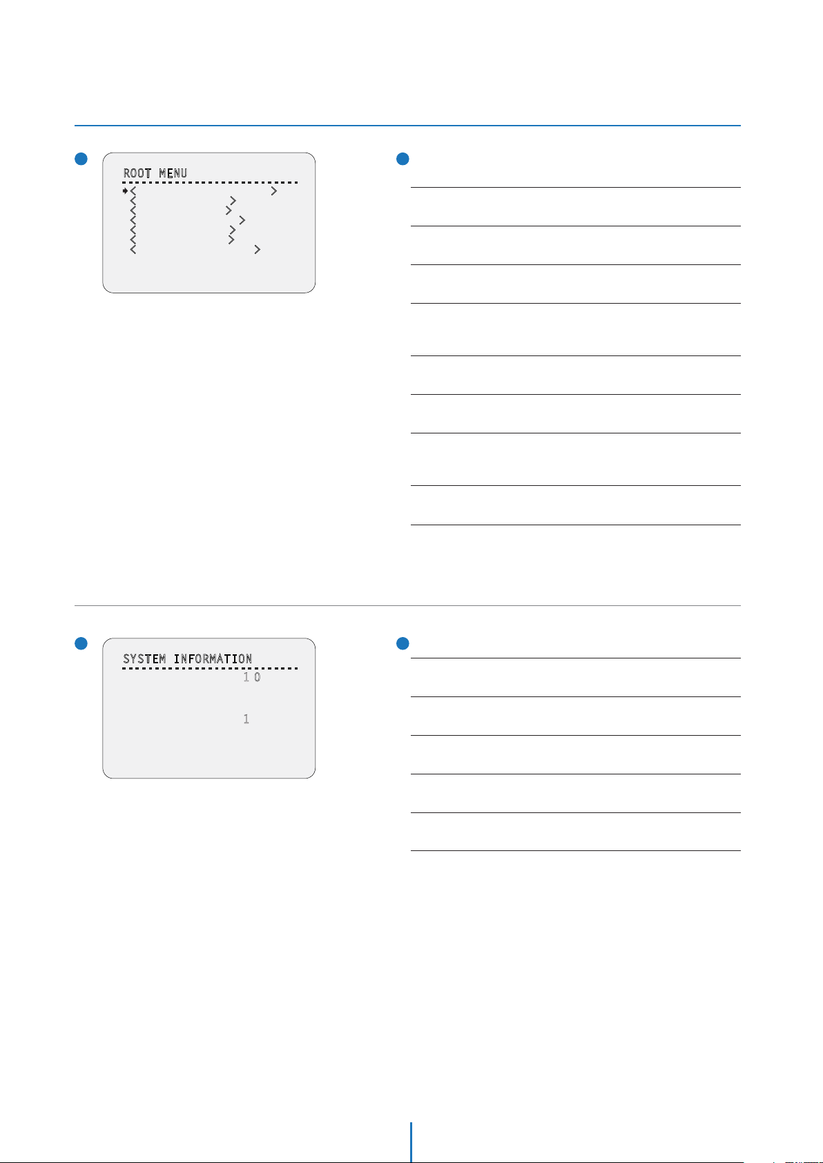
ROOT MENU
ROOT MENU
- - - - - - - - - - - - - - - - - - - - - - - - - - -
<SYSTEM INFORMATION>
<DISPLAY SETUP>
<MOTION SETUP>
<FUNCTION SETUP>
<CAMERA SETUP>
<SYSTEM SETUP>
<SYSTEM INITIALIZE>
To enter this screen, enter ‘Preset key + 95’.
<SYSTEM INFORMATION>
Shows information and current configuration.
<DISPLAY SETUP>
Enable/Disable of OSD display on main screen.
EXIT
SYSTEM INFORMATION
- - - - - - - - - - - - - - - - - - - - - - - - - - -
FIRMWARE VER
COLOR SYSTEM
PROTOCOL
BAUD RATE
ADDRESS
BACK
.0
1
NTSC
PELCO-D
2400
1
<MOTION SETUP>
Setup for motion related settings.
<FUNCTION SETUP>
Setup for various functions such as preset, scan, pattern, group and
schedule.
<CAMERA SETUP>
Configure camera related functions and data.
<SYSTEM SETUP>
Configure for basic system setup.
<SYSTEM INITIALIZE>
Initializes system configuration and sets all data to factory default
configuration.
EXIT
To escape from the OSD setting, go to exit.
11
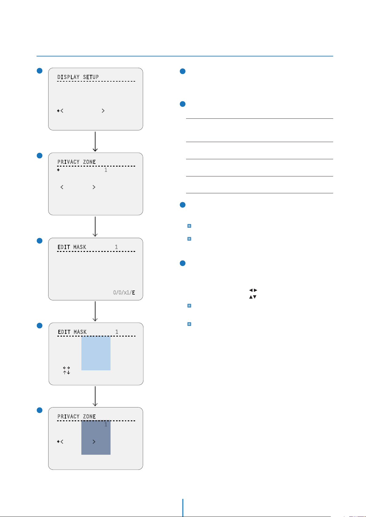
SYSTEM INFORMATION
FIRMWARE VER
Shows the current firmware version.
COLOR SYSTEM
Shows the current analog video system.
PROTOCOL
Shows the current PTZ control protocol.
BAUD RATE
Shows the current baud rate of the PTZ control.
ADDRESS
Shows the current camera ID of the PTZ control.
22
Page 23
OSD -
DISPLAY SETUP (Privacy Zone)
1
DISPLAY SETUP
- - - - - - - - - - - - - - - - - - - - - - - - - - -
CAMERA ID
PTZ INFORMATION
ACTION TITLE
PRESET LABEL
ALARM I/O
DATE/TIME
PRIVACY ZONE>
<
TEMPERATURE CELSIUS
BACK
EXIT
2
2
PRIVACY ZONE
- - - - - - - - - - - - - - - - - - - - - - - - - - -
MASK NO.
DISPLAY
CLEAR
<EDIT MASK>
BACK
EXIT
ON
AUTO
AUTO
AUTO
AUTO
ON
Press Near/Enter Key
1
UNDEFINED
OFF
CANCEL
1
1
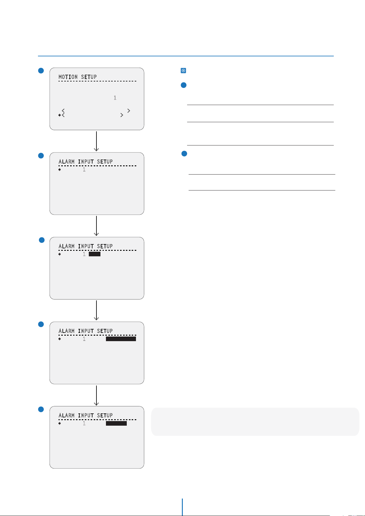
DISPLAY SETUP
This menu defines enable/disable of OSD display on main screen.
If an item is set to be ‘AUTO’, the item is displayed only when the
value of it is changed.
2
2
PRIVACY ZONE
Selects area in image to mask.
MASK NO.
Select mask number. If the selected mask has data already, camera moves
as it was set. Otherwise, ‘UNDEFINED’ will be displayed under ‘MASK NO.’.
DISPLAY
Sets if the camera makes mask shows or not on images.
CLEAR
Deletes data in the selected mask no.
<EDIT MASK>
Moves to setup the mask no.
3
3
EDIT MASK - Move to Target Position
Move camera to area to mask. Then the menu to adjust mask
size will be displayed.
Select <EDIT MASK>,
Press Near/Enter Key
3
3
EDIT MASK 1
- - - - - - - - - - - - - - - - - - - - - - - - - - -
MOVE TO TARGET POSITION
[NEAR:SELECT/FAR:CANCEL]
4
4
EDIT MASK 1
- - - - - - - - - - - - - - - - - - - - - - - - - - -
[ZOOM : COLOR CHANGE]
[ ADJUST MASK WIDTH]
[ ADJUST MASK HEIGHT]
[NEAR:SELECT/FAR:CANCEL]
0/0/x1/E
Move Camera to Area to Mask,
Press Near/Enter Key
> >>
If the tilt angle is located in the range between 90° to 90°, you can not
set up privacy zone mask.
If tilt angle over 90° (image flipped region) is designated, camera will
automatically move to identical position by changing tilt angle less than
90° and moving pan angle 180° relatively.
4
EDIT MASK - Color Change & Adjust Mask Size
Adjust mask size. Use joystick or arrow buttons to adjust mask
size.
- Zoom In/Out: Change Color of Mask.
- Move Joystick Left/Right( ): Adjust Mask Width.
- Move Joystick Up/Down( ): Adjust Mask Height.
To hide a certain zone completely regardless of high speed pan/tilt
motions, it is recommended that the size of mask must be 20%
bigger than original target size.
It is noted that during pan/tilt control like jog action, the object behind
the privacy mask can be disclosed in a short period of time.
Press Near Key to Save
5
5
PRIVACY ZONE
- - - - - - - - - - - - - - - - - - - - - - - - - - -
MASK NO.
DISPLAY
CLEAR
EDIT MASK>
<
BACK
EXIT
1
ON
CANCEL
23
Page 24

OSD -
MOTION SETUP & PARKING ACTION SETUP
11
MOTION SETUP
MOTION SETUP
- - - - - - - - - - - - - - - - - - - - - - - - - - -
PRESET LOCK
PWR UP ACTION
AUTO FLIP
JOG MAX SPEED
JOG DIRECTION
FRZ IN PRESET
<
PARKING ACTION SETUP>
<ALARM INPUT SETUP>
BACK
EXIT
2
PARKING ACTION SETUP
- - - - - - - - - - - - - - - - - - - - - - - - - - -
PARK ENABLE
WAIT TIME
PARK ACTION
OFF
ON
ON
140/SEC
NORMAL
OFF
Press Near/Enter Key
OFF
10:00
00:
HOME
BACK
EXIT
Setup the general functions of pan/tilt motions.
PRESET LOCK
If motion lock is set to on, it is impossible to set up and delete preset,
scan, pattern and group. It is possible only to run those functions.
To set up and delete those functions, enter into OSD menu.
PWR UP ACTION
This function enables to resume the last action executed before power
down. Most of actions such as preset, pattern, scan and group are
available for this function but jog actions are not available to resume.
AUTO FLIP
In case that tilt angle arrives at the top of tilt orbit (90°), zoom module
camera keep moving to opposite tilt direction (180°) to keep tracing
targets. As soon as zoom module camera passes through the top of tilt
direction(90°), images should be reversed automatically and F appears
in screen. If this function is set to ‘OFF’, tilt movement range is 0° ~ 90°.
JOG MAX SPEED
Sets maximum jog speed. Jog speed is inversely proportional to zoom
magnification. As zoom magnification goes up, pan/tilt speed goes down.
JOG DIRECTION
If you set this to ‘NORMAL’, the view in the screen is moving same
direction with jog tilting. If ‘INVERSE’ is selected, the view in the screen
is moving reversely.
FRZ IN PRESET
At start point of preset movement, camera starts freezing the image of
start point. Camera keeps displaying the image of start point during
preset movement and does not display the images which camera gets
during preset movement. As soon as camera stops at preset end point,
camera starts displaying live images which it gets at preset end point.
This function availability should be different by models.
<PARKING ACTION SETUP>
Moves to ‘PARKING ACTION SETUP’ screen.
<ALARM INPUT SETUP>
Moves to ‘ALARM INPUT SETUP’ screen.
‘<ALARM INPUT SETUP>’ is displayed only analog camera.
2
PARKING ACTION SETUP
If ‘PARK ENABLE’ is set to ‘ON’, camera runs assigned function
automatically if there is no PTZ command during assigned
‘WAIT TIME’.
PARK ENABLE
WAIT TIME
The time is displayed with "hh:mm:ss" format and you can change this
by 1 sec. unit.
1. To place the cursor on the time marked as below, press near key.
00:10:00
2. Move joystick Left/Right to adjust hours, minutes and seconds.
3. Move joystick Up/Down to select the digit.
4. By pressing near key, save current setting.
PARKING ACTION
Ex) If ‘HOME’ is selected for park action, camera will move to home
position when there is no PTZ command during the assigned
‘WAIT TIME.’
24
Page 25
OSD -
MOTION SETUP & ALARM INPUT SETUP
1
MOTION SETUP
- - - - - - - - - - - - - - - - - - - - - - - - - - -
PRESET LOCK
PWR UP ACTION
AUTO FLIP
JOG MAX SPEED
JOG DIRECTION
FRZ IN PRESET
<
PARKING ACTION SETUP>
<ALARM INPUT SETUP>
BACK
EXIT
OFF
ON
ON
1
40/SEC
NORMAL
OFF
Press Near/Enter Key
This setup is not supported on some models.
2
ALARM INPUT SETUP
If an external sensor is activated, camera will move to the
corresponding action.
Alarm Type
Sets the sensor input type.
Alarm Action
For each alarm input, you can assign the counteraction functions
(Preset, Scan, Pattern, Group).
>
3
2
ALARM INPUT SETUP
- - - - - - - - - - - - - - - - - - - - - - - - - - -
ALARM 1 N.O
ALARM 2 N.O
BACK
EXIT
NOT USED
NOT USED
Press Near/Enter Key
ALARM TYPE
N.O- Normally Open
N.C- Normally Closed
Note:
Consult your alarm devices manual for N.O and N.C settings.
> >
3
ALARM INPUT SETUP
- - - - - - - - - - - - - - - - - - - - - - - - - - -
ALARM 1 N.O
ALARM 2 N.O
NOT USED
NOT USED
BACK
EXIT
Joystick Right
4
ALARM INPUT SETUP
- - - - - - - - - - - - - - - - - - - - - - - - - - -
ALARM 1 N.O
ALARM 2 N.O
BACK
EXIT
NOT USED
NOT USED
Joystick Down
>
5
ALARM INPUT SETUP
- - - - - - - - - - - - - - - - - - - - - - - - - - -
ALARM 1 N.O
ALARM 2 N.O
BACK
EXIT
PRESET 1
NOT USED
Note: to properly setup a group for the camera, be sure
to have at least 2 Presets, 1 Scan, 1 Patter, and 1 Group setup.
25
Page 26

OSD -
FUNCTION SETUP > PRESET SETUP
What is a Preset?
A Preset is a unique command users can assign the camera.
The PTZ39X supports up to 255 dierent Presets.
Users can use 127 Presets to setup dierent positions for the camera
Users can setup 1~128 Presets for dierent camera positions, except for preset 95.
Preset 95 is reserved for starting the camera’s OSD menu.
For a complete list of all the reserved presets, see below.
See Appendix II for more information on reserved presets.
1
FUNCTION SETUP
- - - - - - - - - - - - - - - - - - - - - - - - - - -
<PRESET SETUP>
<SCAN SETUP>
<PATTERN SETUP>
<GROUP SETUP>
<SCHEDULE SETUP>
BACK
EXIT
Press Near/Enter Key
> > >
2
PRESET SETUP
- - - - - - - - - - - - - - - - - - - - - - - - - - -
PRESET NO.
<
EDIT SCENE>
BACK
EXIT
1
UNDEFINED
1
FUNCTION SETUP
Configure 5 special functions with this menu.
2
PRESET SETUP - Undefined
PRESET NO.
If a selected preset is already defined, camera moves to pre-defined
position and preset characteristics such as label and relay outputs
show on monitor. (Refer screen 4) If a selected preset is not defined,
‘UNDEFINED’ shows on monitor.
<EDIT SCENE>
Redefine the current preset scene position(i.e. PTZ).
3
EDIT SCENE
1. Using joystick, move camera to the desired position.
2. By pressing near key, save the current PTZ data.
3. Press far key to cancel.
4
PRESET SETUP
If the preset is defined, the information will be shown on the
OSD menu with the setting, and the alarm device (if defined)
will be activated.
3
EDIT SCENE -PRESET1
- - - - - - - - - - - - - - - - - - - - - - - - - - -
MOVE TO TARGET POSITION
[NEAR:SELECT/FAR:CANCEL]
4
PRESET SETUP
- - - - - - - - - - - - - - - - - - - - - - - - - - -
PRESET NO.
<
EDIT SCENE>
<LABEL>
CLR PRESET
CAM ADJUST
ALARM OUT
BACK
EXIT
Select <EDIT SCENE>,
Press Near/Enter Key
0/0/x1/E
Press Near/Enter Key
1
CANCEL
GENERAL
-
PRESET NO.
<EDIT SCENE>
<LABEL>
Edits Label to show on monitor when preset runs. Max. 10 alphabets
are allowed.
CAM ADJUST
- WB(White Balance) and AE(Auto Exposure) can be set up independently
for each preset.
- GENERAL: WB or AE can be set up totally and simultaneously for all
presets in ‘ROOT MENU>CAMERA SETUP’ menu.
- SPECIAL: WB or AE can be set up independently or separately for each
preset in each preset setup menu.
- Each special WB/AE value should the activated correspondingly when
camera arrives at each preset location. During jog operation, general
WB/AE value should be applied.
- All special WB/AE value should not be changed although general
WB/AE value is changed. If ‘SPECIAL’ is selected, the menu to set WB/AE
is shown on monitor.
ALARM OUT
Relay output can be linked with preset run. ‘ - ‘means off, ‘1’ means on.
26
Page 27

OSD -
FUNCTION SETUP > PRESET SETUP
2
1
PRESET SETUP
- - - - - - - - - - - - - - - - - - - - - - - - - - -
PRESET NO.
<
EDIT SCENE>
<LABEL>
CLR PRESET
CAM ADJUST
ALARM OUT
BACK
EXIT
1
CANCEL
GENERAL
-
Press Near/Enter Key
LABEL
Edits label to show on monitor when camera arrives at preset.
LABEL PRESET1
a
b
- - - - - - - - - - - - - - - - - - - - - - - - - - -
[ ]
- - - - - - - - - -
1 2 3 4 5 6 7 8 9 0
A B C D E F G H I J
K L M N O P Q R S T
U V W X Y Z a b c d
e f g h i j k l m n
o p q r s t u v w x
y z
< >
- / : .
OK
CANCEL
2
LABEL PRESET1
- - - - - - - - - - - - - - - - - - - - - - - - - - -
[ ]
- - - - - - - - - -
1 2 3 4 5 6 7 8 9 0
A B C D E F G H I J
K L M N O P Q R S T
U V W X Y Z a b c d
e f g h i j k l m n
o p q r s t u v w x
y z
< >
- / : .
OK
CANCEL
Press Near/Enter Key
a
Current Cursor Position: In edit label menu, a reverse rectangular
is cursor. As soon as finishing selecting alphabet, cursor moves to
the next digit.
b
Selecting Alphabet: Using left/right/up/down of joystick, move
to an appropriate character from the character set. To choose the
character, press the near or enter key.
c
Space: If you want to use blank, choose space character (’ ‘).
d
Back-Space:
space character (’ ‘).
If you want to delete a character in front, use back
c
d
>
3
3
LABEL PRESET1
- - - - - - - - - - - - - - - - - - - - - - - - - - -
[ ]
S K Y
- - - - - - - - - -
1 2 3 4 5 6 7 8 9 0
A B C D E F G H I J
K L M N O P Q R S T
U V W X Y Z a b c d
e f g h i j k l m n
o p q r s t u v w x
y z
1
PRESET SETUP
- - - - - - - - - - - - - - - - - - - - - - - - - - -
PRESET NO.
<
<LABEL>
CLR PRESET
CAM ADJUST
ALARM OUT
BACK
EXIT
- / : .
< >
EDIT SCENE>
OK
CANCEL
1
CANCEL
<
SPECIAL>
-
LABEL – Complete Editing
If you complete the label editing, move cursor to ‘OK’ and press
near key to save completed label. To abort current change, move
cursor to ‘CANCEL’ and press near key.
2
CAM ADJUST
Edits label to show on monitor when the camera arrives at
presets.
<WHITE BALANCE SETUP>
See the section ‘ROOT MENU>CAMERA SETUP>WB SETUP’.
<AUTO EXPOSURE SETUP>
See the section ‘ROOT MENU>CAMERA SETUP>AE SETUP’.
Press Near/Enter Key
>
2
CAM ADJUST -PRESET1
- - - - - - - - - - - - - - - - - - - - - - - - - - -
<WHITE BALANCE SETUP>
<AUTO EXPOSURE SETUP>
BACK
EXIT
27
Page 28

OSD -
FUNCTION SETUP > SCAN SETUP
1
FUNCTION SETUP
- - - - - - - - - - - - - - - - - - - - - - - - - - -
<PRESET SETUP>
<SCAN SETUP>
<PATTERN SETUP>
<GROUP SETUP>
<SCHEDULE SETUP>
BACK
EXIT
2
SCAN SETUP
By using the scan function, you can make the camera to move
between 2 preset positions repeatedly.
When the scan function runs, the camera moves from the
preset assigned as the 1st point to the preset assigned as the
2nd point in CW(Clockwise) direction. Then the camera moves
from the preset assigned as the 2nd point to the preset
assigned as the 1st point in CCW(Counterclockwise) direction.
In case that the preset assigned as the 1st point is same as the
preset assigned as the 2nd point, the camera turns on its axis
Press Near/Enter Key
>
2
SCAN SETUP
- - - - - - - - - - - - - - - - - - - - - - - - - - -
SCAN NO.
1
ST POS.
2ND POS.
SCAN SPEED
CLEAR SCAN
BACK
EXIT
1
NOT USED
NOT USED
30
/SEC
CANCEL
by 360° in CW direction and then it turns on its axis by 360°
in CCW direction.
2nd POS.
2. CCW direction
1. CW direction
SCAN NO.
Selects the scan number to edit. If a selected scan has not defined,
‘NOT USED’ is displayed in 1st position and 2nd position.
1st POS.
1ST POS. / 2 ND POS.
Set up the 2 position for scan function. If a selected preset is not defined,
‘UNDEFINED’ will be displayed as shown below.
SCAN SETUP
- - - - - - - - - - - - - - - - - - - - - - - - - - -
SCAN NO.
1ST POS.
2ND POS.
SCAN SPEED
SCAN SPEED
Sets the scan speed.
CLEAR SCAN
Deletes the current scan data.
1
PRESET 1
NOT USED
UNDEFINED
30
/SEC
Note: to properly setup a scan for the camera, be sure to have at least 2 Presets setup.
28
Page 29

OSD -
FUNCTION SETUP > PATTERN SETUP
1
FUNCTION SETUP
- - - - - - - - - - - - - - - - - - - - - - - - - - -
<PRESET SETUP>
<SCAN SETUP>
<PATTERN SETUP>
<GROUP SETUP>
<SCHEDULE SETUP>
BACK
EXIT
Press Near/Enter Key
> > > >
2
PATTERN SETUP
- - - - - - - - - - - - - - - - - - - - - - - - - - -
PATTERN NO.
CLEAR PATTERN
<
EDIT PATTERN>
BACK
EXIT
3
EDIT PATTERN 1
- - - - - - - - - - - - - - - - - - - - - - - - - - -
MOVE TO START POSITION
[NEAR:START/ FAR:CANCEL]
1
UNDEFINED
CANCEL
Select <EDIT PATTERN>,
Press Near/Enter Key
0/0/x1/E
2
PATTERN SETUP
Pattern function is that a camera memorizes the path (mostly
curve path) by joystick of controller for assigned time and
revives the path exactly as it memorized.
4 patterns are available and max. 1000 communication
commands can be stored in a pattern.
PATTERN NO.
Select pattern number to edit. If a selected pattern number is not defined,
‘UNDEFINED’ will be displayed under selected pattern number.
CLR PATTERN
Deletes data in the current pattern.
<EDIT PATTERN>
Starts editing pattern.
3
EDIT PATTERN - Select the Position
1. By using joystick, move to the start position with appropriate
zoom.
2. To start the pattern recording, press near or enter key.
3. To exit this menu, press far key.
4
EDIT PATTERN - Records
1. Move the camera with joystick of the controller or run preset
function to memorize the path (mostly curve path) in a
selected pattern.
2. The total memory size and the rest memory size is displayed
in the form of bar.
3. To save data and exit, press near key.
4. To cancel recording and delete the recorded data, press far
key.
Move Camera to Area,
Press Near/Enter Key
4
EDIT PATTERN 1
[NEAR:SAVE / FAR:DELETE]
5
EDIT PATTERN 1
[NEAR:SAVE / FAR:DELETE]
0/0/x1/E
Record the Path of the Pattern
by Camera Control
0/0/x1/E
Note: to properly setup a pattern for the camera,
be sure to have at least 2 Presets, and 1 Scan setup.
29
Page 30

OSD -
FUNCTION SETUP > GROUP SETUP
1
FUNCTION SETUP
- - - - - - - - - - - - - - - - - - - - - - - - - - -
<PRESET SETUP>
<SCAN SETUP>
<PATTERN SETUP>
<GROUP SETUP>
<SCHEDULE SETUP>
BACK
EXIT
Press Near/Enter Key
> > > >
2
GROUP SETUP
- - - - - - - - - - - - - - - - - - - - - - - - - - -
GROUP NO.
CLEAR GROUP
<
EDIT GROUP>
BACK
EXIT
3
EDIT GROUP 1
- - - - - - - - - - - - - - - - - - - - - - - - - - -
NO. ACTION NO. DWELL OPT
- - - - - - - - - - - - - - - - - - - - - - - - - -
1
NONE
2 NONE
3 NONE
4 NONE
5 NONE
- - - - - - - - - - - - - - - - - - - - - - - - - -
SAVE
CANCEL [NEAR:EDIT]
1
UNDEFINED
CANCEL
Select <EDIT GROUP>,
Press Near/Enter Key
Press Near/Enter Key
2
GROUP SETUP SCREEN
The group function allows running sequence of presets, pattern
and/or scans. Each group can have
max. 20 action entities which
can be preset, pattern or scan.
Preset speed can be set up and the repeat number of pattern
& scan can be set up in group setup. Dwell time between
actions can be set up also.
Dwell Time
Preset
1
GROUP NO.
Selects group number to edit. If a selected group number is not defined,
‘UNDEFINED’ will be displayed under the selected group number.
CLEAR GROUP
Deletes data in the current group.
<EDIT GROUP>
Starts editing group.
3
EDIT GROUP - Initial Screen
Pattern5
1 Times
Pattern5
n Times
Max. 20 Entities
Scan3
1
Preset
120
Press near or enter key in ‘NO’ list to start group setup.
ACTION NO.
Sets the function and function number.
DWELL TIME
Sets dwell time between function by moving joystick up/down.
OPT
It represents preset speed when preset is selected. It should be the
number of repetition when pattern or scan is selected for ‘ACTION’.
4
EDIT GROUP 1
- - - - - - - - - - - - - - - - - - - - - - - - - - -
NO. ACTION NO. DWELL OPT
- - - - - - - - - - - - - - - - - - - - - - - - - -
NONE
1
2 NONE
3 NONE
4 NONE
5 NONE
- - - - - - - - - - - - - - - - - - - - - - - - - -
SAVE
CANCEL
5
EDIT GROUP 1
- - - - - - - - - - - - - - - - - - - - - - - - - - -
NO. ACTION NO. DWELL OPT
- - - - - - - - - - - - - - - - - - - - - - - - - -
1
2 NONE
3 NONE
4 NONE
5 NONE
- - - - - - - - - - - - - - - - - - - - - - - - - -
SAVE
CANCEL
[NEAR:EDIT ACT]
[FAR :EDIT END]
NONE
[ :
[ : CHANGE VAL.]
Press Near/Enter Key
MOVE CURSOR
]
4
EDIT GROUP – Select Function Sequence
Note that max. 20 functions are allowed in a group.
Move cursor up/down and press near or enter key to set up.
6
5
EDIT GROUP - Assign Function
Set up ‘ACTION, ‘DWELL’ and ‘OPT’. Note that selected item is
displayed in reverse. Move cursor left/right to select items and
move cursor up/down to change each value.
30
Page 31

OSD -
FUNCTION SETUP > GROUP SETUP
6
EDIT GROUP 1
- - - - - - - - - - - - - - - - - - - - - - - - - - -
NO. ACTION NO. DWELL OPT
- - - - - - - - - - - - - - - - - - - - - - - - - -
1
PATTERN 1 00 : 0
2 NONE
3 NONE
4 NONE
5 NONE
- - - - - - - - - - - - - - - - - - - - - - - - - -
SAVE
CANCEL
[ :
MOVE CURSOR
[ : CHANGE VAL.]
3 1
]
7
EDIT GROUP - Selects Function Sequence
After finishing setting up an ‘ACTION’, press near or enter key
to one-upper-level menu. Move cursor up/down to select
‘ACTION NO.’ and repeat to step 4 ~ step 6 to edit the selected
64
group.
8
EDIT GROUP - Saves the Setting
After finishing setting up all actions, press far key to exit.
Then cursor should be moved to ‘SAVE’. Press near or enter
key to save the data.
Press Near/Enter Key
> >
7
EDIT GROUP 1
- - - - - - - - - - - - - - - - - - - - - - - - - - -
NO. ACTION NO. DWELL OPT
- - - - - - - - - - - - - - - - - - - - - - - - - -
1
PATTERN 1 00 : 0
2 NONE
3 NONE
4 NONE
5 NONE
- - - - - - - - - - - - - - - - - - - - - - - - - -
SAVE
CANCEL
8
EDIT GROUP 1
- - - - - - - - - - - - - - - - - - - - - - - - - - -
NO. ACTION NO. DWELL OPT
- - - - - - - - - - - - - - - - - - - - - - - - - -
1
2 NONE
3 NONE
4 NONE
5 NONE
- - - - - - - - - - - - - - - - - - - - - - - - - -
SAVE
CANCEL
[NEAR:EDIT ACT]
[FAR :EDIT END]
PATTERN 1 00 : 0
3 1
Press Far Key
3 1
Note: to properly setup a group for the camera, be sure to have at least 2 Presets,
1 Scan, and 1 Patter setup.
31
Page 32

OSD -
FUNCTION SETUP > SCHEDULE SETUP
1
FUNCTION SETUP
- - - - - - - - - - - - - - - - - - - - - - - - - - -
<PRESET SETUP>
<SCAN SETUP>
<PATTERN SETUP>
<GROUP SETUP>
<SCHEDULE SETUP>
BACK
EXIT
2
SCHEDULE SETUP SCREEN
The schedule function allows running an appropriate function
like preset, scan, pattern, group, home move at designated
day and time.
EX) If you setup a rule ‘Tuesday at 9:00AM’ and ‘Preset 1(say main
gate)’, the camera will move to main gate every Tuesday at 9:00
AM. If you choose weekday, camera will move to main gate
everyday except weekend.
It is noted that due to the real time clock(ROOT MENU>
SYSTEM SETUP>DATA/TIME SETUP), the time data will be kept
Press Near/Enter Key
> > > >
2
SCHEDULE SETUP
- - - - - - - - - - - - - - - - - - - - - - - - - - -
MASTER ENABLE OFF
DAY TIME ACT NO ON
1
UNDEFINED
2 UNDEFINED
3 UNDEFINED
4 UNDEFINED
5 UNDEFINED
6 UNDEFINED
7 UNDEFINED
BACK
Joystick Down,
Press Near Key
3
SCHEDULE SETUP
- - - - - - - - - - - - - - - - - - - - - - - - - - -
MASTER ENABLE OFF
DAY TIME ACT NO ON
UNDEFINED
1
2 UNDEFINED
3 UNDEFINED
4 UNDEFINED
5 UNDEFINED
6 UNDEFINED
7 UNDEFINED
BACK
regardless of blackout. The initial time and day setup is
essential to proper schedule function.
MASTER ENABLE
Decide whether schedule function is active or not.
DAY
Set the day for scheduling.
- Undefined: Inactivate
- All: Applies to every day
- WKD: Applies to every day except Saturday and Sunday
- SUN-MON: Applies to designated day only
TIME
Set the time.
ACT NO
Set the function and function number.
ON
Decide to make this rule effective or not.
4
5
SCHEDULE SETUP - Assign Value
Each field (DAY, TIME, ACT, NO., ON) can be selected by Left/Right
keys and the values in the field are changed using Up/Down keys.
Joystick Down
4
SCHEDULE SETUP
- - - - - - - - - - - - - - - - - - - - - - - - - - -
MASTER ENABLE OFF
DAY TIME ACT NO ON
ALL 00 : 0 0 HOM OFF
1
2 UNDEFINED
3 UNDEFINED
4 UNDEFINED
5 UNDEFINED
6 UNDEFINED
7 UNDEFINED
BACK
Assign Value
5
SCHEDULE SETUP
- - - - - - - - - - - - - - - - - - - - - - - - - - -
MASTER ENABLE OFF
DAY TIME ACT NO ON
ALL 12: 0 0 PRS 128 ON
1
2 UNDEFINED
3 UNDEFINED
4 UNDEFINED
5 UNDEFINED
6 UNDEFINED
7 UNDEFINED
BACK
32
Page 33

OSD -
FUNCTION SETUP > SCHEDULE SETUP
6
SCHEDULE SETUP
- - - - - - - - - - - - - - - - - - - - - - - - - - -
MASTER ENABLE ON
DAY TIME ACT NO ON
1
MON 01: 20 HOM ON
2 WED 07:00 PRS 1
3 THU 11
4 ALL 1
5 UNDEFINED
6 UNDEFINED
7 UNDEFINED
BACK
:4 0 SCN 3 ON
2:00 SCN 1 ON
2 ON
EX)
The second rule means camera will move to preset 12 position at
7:00 on every wednesday.
If there are rules conflicts to each other, the higher number is the higher
priority has.
If you assign undefined function, there will be no action.
Using reserved preset, you can make various schedules.
For example, PRS125 and PRS124 are ‘DAY’ and ‘NIGHT’ mode respectively.
(Refer to Reserved Preset list in this manual.)
Note: to properly setup a schedule for the camera, be sure to have at least 2 Presets,
1 Scan, 1 Patter, and 1 Group setup.
33
Page 34

OSD -
CAMERA SETUP > WHITE BALANCE SETUP
1
ZOOM CAMERA SETUP
- - - - - - - - - - - - - - - - - - - - - - - - - - -
FOCUS MODE
DIGITAL ZOOM
IMAGE FLIP
FLICKERLESS
<
WHITE BALANCE SETUP>
<AUTO EXPOSURE SETUP>
<SPECIAL>
BACK
EXIT
2
WB SETUP
- - - - - - - - - - - - - - - - - - - - - - - - - - -
WB MODE
- RED ADJUST
- BLUE ADJUST
BACK
EXIT
3
WB SETUP
- - - - - - - - - - - - - - - - - - - - - - - - - - -
WB MODE
- RED ADJUST
- BLUE ADJUST
BACK
EXIT
SEMIAUTO
OFF
OFF
OFF
Press Near/Enter Key
> > > >
AUTO
- - -
- - -
Press Near Key,
Joystick Down
MANUAL
3 0
4 0
1
ZOOM CAMERA SETUP
Setup the general functions of zoom camera module.
FOCUS MODE
Sets the camera focus mode.
- AUTO: Focus is exchanges automatically in this mide.
- SEMIAUTO: This mode exchanges the focus mode automatically
between manual focus mode and auto focus mode. Manual focus
mode activates in preset operation and auto focus mode activates
when jog operation starts.
- MANUAL: With manual mode at presets, focus data is memorized in
each preset in advance and camera calls focus data in correspondence
with presets as soon as camera arrives at a preset.
DIGITAL ZOOM
Sets digital zoom function to ‘ON’ or ‘OFF’. If this is set to ‘OFF’, optical
zoom function runs but zoom function stops at the end of optical zoom
magnification.
IMAGE FLIP
Sets if the image should be reversed or not.
FLICKERLESS
Turns on or off the flickerless function. In this function, AE mode
becomes shutter priority mode and shutter speed value will be fixed
to 1/100 sec.
<WHITE BALANCE SETUP>
Starts ‘WHITE BALANCE SETUP’ setup screen.
<AUTO EXPOSURE SETUP>
Starts ‘AUTO EXPOSURE SETUP’ setup screen.
<SPECIAL>
Starts ‘SPECIAL’ setup screen.
This setup is not supported on some models.
2
Press Near/Enter Key
4
WB SETUP
- - - - - - - - - - - - - - - - - - - - - - - - - - -
WB MODE
- RED ADJUST
- BLUE ADJUST
BACK
EXIT
5
WB SETUP
- - - - - - - - - - - - - - - - - - - - - - - - - - -
WB MODE
- RED ADJUST
- BLUE ADJUST
BACK
EXIT
MANUAL
3 0
4 0
Joystick Down
MANUAL
3 0
4 0
WB SETUP
WB MODE
- AUTO: Camera perform white balance automatically.
- Manual: R/B gain level can be set up manually.
- ATW: Auto White Balance is performed in the wider range of color
temperature than that of the 'AUTO' mode.
- AWC: When right direction key is clicked, one time white balance is
performed for current illumination condition and the value is kept.
- INDOOR: WB will be done under assumption of Indoor illumination.
- OUTDOOR: WB will be done under assumption of Sun light.
RED ADJUST
BLUE ADJUST
34
Page 35

OSD -
CAMERA SETUP > AUTO EXPOSURE SETUP
1
ZOOM CAMERA SETUP
- - - - - - - - - - - - - - - - - - - - - - - - - - -
FOCUS MODE
DIGITAL ZOOM
IMAGE FLIP
FLICKERLESS
<
WHITE BALANCE SETUP>
<AUTO EXPOSURE SETUP>
<SPECIAL>
BACK
EXIT
2
AE SETUP
- - - - - - - - - - - - - - - - - - - - - - - - - - -
WDR/BLC
DAY/NIGHT
AE MODE
IRIS LEVEL
GAIN LEVEL
SHUTTER SPD
BRIGHTNESS
SENS-UP
BACK
EXIT
SEMIAUTO
ON
OFF
OFF
Press Near/Enter Key
>
ALL OFF
AUTO
AUTO
---
---
-- 8
X8
2
AE SETUP
WDR/BLC
Sets the backlight compensation.
DAY/NIGHT
‘AUTO’ exchanges day/night.
AE MODE
- AUTO: Full auto mode for AE function
- MANUAL: In manual mode. ‘IRIS’, ‘GAIN’, ‘SHUTTER SPEED’ can be
changed in this mode.
- IRIS: Iris priority mode. You can change iris while others are adjusted
automatically.
- SHUTTER: Shutter priority mode. Shutter speed can be changed while
while others are adjusted automatically.
- BRIGHT: In this mode, you can assign AE value in terms of brightness.
IRIS LEVEL
Works when ‘AE MODE’ is ‘MANUAL’ or ‘IRIS’ mode.
GAIN LEVEL
Works when ‘AE MODE’ is ‘MANUAL’. Enhances image brightness
automatically in case that luminance level of image signal is too low.
SHUTTER SPD
Works when ‘AE MODE’ is ‘MANUAL’ or ‘SHUTTER’ mode.
BRIGHTNESS
Works when ‘AE MODE’ is ‘BRIGHT’. Adjusts brightness of images. Iris,
shutter speed and gain are adjusted automatically in correspondence
with this value.
SENS-UP
35
Page 36
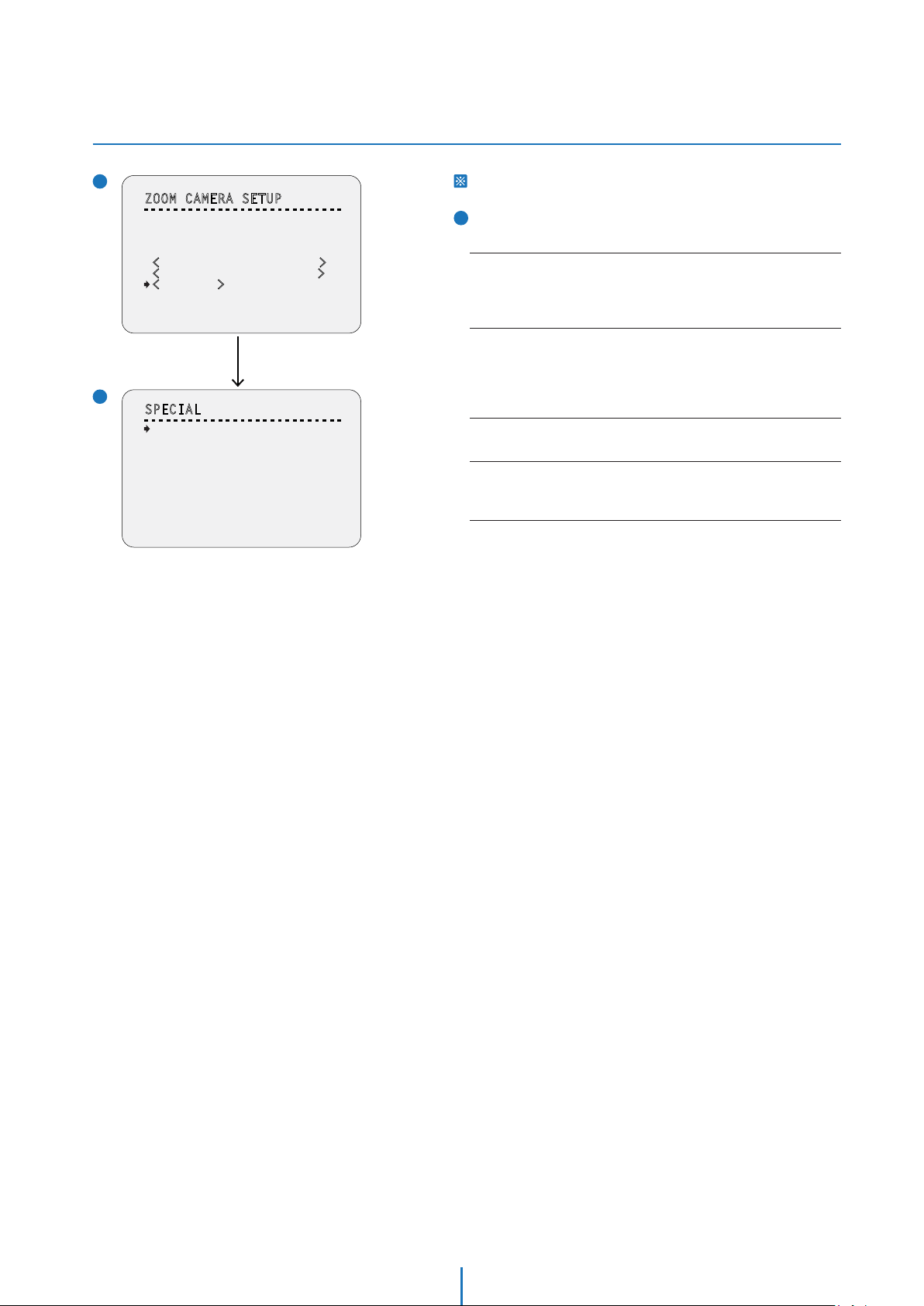
OSD -
CAMERA SETUP > SPECIAL (HLC/ DNR)
1
ZOOM CAMERA SETUP
- - - - - - - - - - - - - - - - - - - - - - - - - - -
FOCUS MODE
DIGITAL ZOOM
IMAGE FLIP
FLICKERLESS
<
WHITE BALANCE SETUP>
<AUTO EXPOSURE SETUP>
<SPECIAL>
BACK
EXIT
2
SPECIAL
- - - - - - - - - - - - - - - - - - - - - - - - - - -
DNR
DETAIL
HR
HLC
BACK
EXIT
SEMIAUTO
ON
OFF
OFF
Press Near/Enter Key
OFF
5
OFF
OFF
This setup is not supported on some models.
2
SPECIAL
Sets the special function relaced to the image.
DNR
If reduces the noise caused by ‘AGC’ action. If set to AUTO or MANUAL,
the noise will be reduced but the ghost effect on moving objects will
be increased. If enabled, select the apropriate level from 1~10.
DETAIL
Selects if the sub screen will be displayed. Sub screen will be displayed
on the bottom of the right side. Even though the main image enables
the digital zoom, the sub screen will only display with maximum optical
zoom.
HR(High Resolution)
This mode enhances edges and produces higher definition images.
HLC
Part where becomes brightness more than the standard value is
automatically hid by mask on the video.
36
Page 37

OSD -
SYSTEM SETUP
1
SYSTEM SETUP
- - - - - - - - - - - - - - - - - - - - - - - - - - -
<DATE/TIME SETUP>
<RELAY TYPE>
<PASSWORD>
<SET HOME POSITION>
<SET NORTH DIRECTION>
LANGUAGE
FAN HEATER SETUP>
<
<PROTOCOL/BAUDRATE>
BACK
EXIT
2
DATE/TIME SETUP
- - - - - - - - - - - - - - - - - - - - - - - - - - -
DATE
TIME
BACK
EXIT
3
RELAY TYPE SETUP
- - - - - - - - - - - - - - - - - - - - - - - - - - -
RELAY1
ENGLISH
01/JAN/2008(TUE)
00:00:0
1(H/M/S)
NORMAL OPEN
1
SYSTEM SETUP
<DATE/TIME SETUP>
Start ‘DATE/TIME SETUP’ setup.
‘<DATE/TIME SETUP>’ is displayed only analog camera.
<RELAY TYPE>
Start ‘RELAY TYPE’ setup.
<PASSWORD>
Start ‘PASSWORD’ setup.
<SET HOME POSITION>
Starts ‘SET HOME POSITION’ setup. See the screen 4 below.
<SET NORTH DIRECTION>
Starts ‘SET NORTH DIRECTION’ setup.
LANGUAGE
You can select a preferred Language of OSD display. After selecting
a language, press near or enter key.
<FAN HEATER SETUP>
Moves to ‘FAN HEATER SETUP’ screen.
This setup is only applicable for fan/heater model.
<PROTOCOL/BAUDRATE>
Moves to ‘PROTOCAL/BAUDRATE’ screen.
2
DATE/TIME SETUP
This setup is not supported on some models.
BACK
EXIT
4
EDIT PASSWORD
- - - - - - - - - - - - - - - - - - - - - - - - - - -
[ ]
- - - - - - - - - -
1 2 3 4 5 6 7 8 9 0
A B C D E F G H I J
K L M N O P Q R S T
U V W X Y Z a b c d
e f g h i j k l m n
o p q r s t u v w x
y z
< >
- / : .
OK
CANCEL
DISABLE
DATE
Date is displayed in dd/mm/yy format.
1. If you press the near key, the focus will be placed on ‘dd’.
2. Sets date moving joystick Up/Down.
3. Moves joystick Left/Right to move to date-month-year.
4. The values in the field are changed using Up/Down keys.
The day is automatically calculated when you set the day.
TIME
Time is displayed in HH:MM:SS format.
Sets time same as setting date.
3
RELAY TYPE SETUP
RELAY1
Contacts type of of 1ch. Relay out are defined.
4
EDIT PASSWORD
Sets the 4 characters long password. If this function is set to
‘ENABLE’, the password is required whenever you enter OSD
SET HOME POSITION
- - - - - - - - - - - - - - - - - - - - - - - - - - -
MOVE TO TARGET POSITION
[NEAR:SELECT/FAR:CANCEL]
0/0/x1/E
menu.
The default password is ‘4321’ and the master password is ‘- - > g’.
37
Page 38
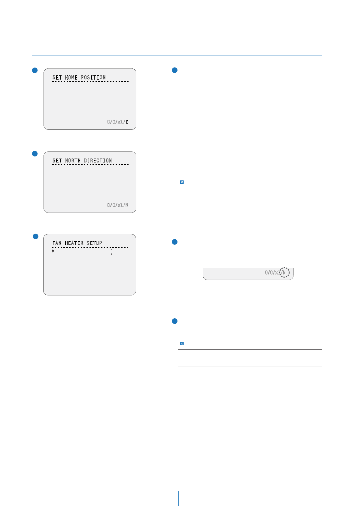
OSD -
SYSTEM SETUP
5
SET HOME POSITION
- - - - - - - - - - - - - - - - - - - - - - - - - - -
MOVE TO TARGET POSITION
[NEAR:SELECT/FAR:CANCEL]
6
SET NORTH DIRECTION
- - - - - - - - - - - - - - - - - - - - - - - - - - -
MOVE TO TARGET POSITION
[NEAR:SELECT/FAR:CANCEL]
0/0/x1/E
0/0/x1/N
5
SET HOME POSITION
Home position means the origin of pan angle calculation.
The value of pan angle displayed on the screen is based on this
home position. Home is not effective to tilt angle.
By using joystick, move the camera to the desired position and
press near key.
If you change the location of the home position, all horizontal
location of functions such as preset, scan, pattern, group and
privacy zone mask will be shifted based on the changed home
position.
If there are no setup for those functions like preset, pattern,
scan, group camera will automatically move to home position
after rebooting.
If power up action is set to be on, camera will continue the
function which is executed lastly after rebooting.
Set Home Position?
When you replace the camera block or the orientation of camera is
changed due to maintenance operations, it is very difficult to maintain
the same pan orientation. Therefore, all function data maintain on
pan orientation such as preset, scan, pattern, group and privacy zone
mask are not useful any more accordingly.
However, even in this case, you can reuse the data if you redefine set
home position on the previous home position.
7
FAN HEATER SETUP
- - - - - - - - - - - - - - - - - - - - - - - - - - -
FAN RUN TEMP
HEATER RUN TEMP
BACK
EXIT
25 C
5 C
6
SET NORTH DIRECTION
By using joystick, move the camera to the desired north
position and press enter (near/save).
The direction will be displayed in the screen
[NEAR:SELECT/FAR:CANCEL]
0/0/x1/N
Direction will be displayed from:
N(North) / S(South) / E(East) / W(West) / NE(Northeast) /
NW(Northwest) / SE(Southeast) / SW(Southwest).
7
FAN HEATER SETUP
Sets the fan/heater enabled/disabled according to the
temperature.
This menu will be displayed only for fan/heater model.
FAN RUN TEMP
Above this temperature, the blower fan will start automatically.
HEATER RUN TEMP
Below this temperature, the heater will be tuned on automatically.
38
Page 39

OSD -
SYSTEM SETUP (BAUDRATE & PROTOCOL)
8
SYSTEM SETUP
- - - - - - - - - - - - - - - - - - - - - - - - - - -
<DATE/TIME SETUP>
<RELAY TYPE>
<PASSWORD>
<SET HOME POSITION>
<SET NORTH DIRECTION>
LANGUAGE
FAN HEATER SETUP>
<
<PROTOCOL/BAUDRATE>
BACK
EXIT
PROTOCOL/BAUDRATE
- - - - - - - - - - - - - - - - - - - - - - - - - - -
PROTOCOL
BAUDRATE
BACK
EXIT
PROTOCOL/BAUDRATE
- - - - - - - - - - - - - - - - - - - - - - - - - - -
PROTOCOL
BAUDRATE
BACK
EXIT
ENGLISH
Press the
Near/Enter Key
>
PELCO-D
2400
Press the
Near/Enter Key
> >
PELCO-D
2400
8
PROTOCOL/BAUDRATE
After installing the camera, you should set the communication
protocol and baudrate.
PROTOCOL
- Select the appropriate protocol.
- If you set the protocol as ‘Auto’ protocol, camera will automatically
recognize PELCO-D, PELCO-P or SAMSUNG protocol.
- If you want to control using DVR or system keyboard, their protocol
must be identical to camera. Otherwise, you can not control the camera.
- If you change camera protocol by changing DIP switch, the change will
be effective after you reboot the camera.
BAUDRATE
Select the appropriate baud rate.
Move the
Joystick Down
PROTOCOL/BAUDRATE
- - - - - - - - - - - - - - - - - - - - - - - - - - -
PROTOCOL
BAUDRATE
BACK
EXIT
PELCO-P
2400
39
Page 40

OSD -
SYSTEM INITIALIZE
SYSTEM INITIALIZE
- - - - - - - - - - - - - - - - - - - - - - - - - - -
CLEAR ALL DATA
CLR DISPLAY SET
CLR CAMERA SET
CLR MOTION SET
CLR FUNCTION SET
REBOOT CAMERA
REBOOT SYSTEM
BACK
EXIT
NO
NO
NO
NO
NO
NO
NO
Initial Configuration Table
Camera ID
PTZ Information
Action Title
Preset Label
Alarm I/O
Date/Time
Privacy Zone
Temperature
ON
AUTO
AUTO
AUTO
AUTO
ON
Undefined
OFF
Display
SYSTEM INITIALIZE
CLEAR ALL DATA
Deletes all configuration data such as display, camera, motion
setup and so on.
CLR DISPLAY SET
Initializes display configuration.
CLR CAMERA SET
Initializes camera configuration.
CLR MOTION SET
Initializes motion configuration.
CLR FUNCTION SET
Deletes preset, scan, pattern, group and schedule data.
REBOOT CAMERA
Reboots zoom camera module.
REBOOT SYSTEM
Reboots speed dome camera.
YES / NO
YES / NO
YES / NO
YES / NO
YES / NO
YES / NO
YES / NO
Preset Lock
Power Up Action
Auto Flip
Jog Max Speed
Jog Direction
Freeze In Preset
Park Action
Preset
Scan
Pattern
Group
Schedule
Focus Mode
Digital Zoom
Image Flip
Flickerless
White Balance
WDR/BLC
Day/Night
AE Mode
Iris Level
Gain Level
Shutter Speed
Brightness
Sens-up
DNR
Detail
HR
HLC
OFF
ON
ON
140°/sec
NORMAL
OFF
OFF
Undefined
Undefined
Undefined
Undefined
Undefined
AUTO
OFF
OFF
OFF
ATW
ALL OFF
AUTO
AUTO
-
-
8
X8
AUTO
5
ON
OFF
Motion
Function
Camera
Relay Type
Language
Fan Run Temp
Heater Run Temp
Protocol
Baud Rate
40
Normal Open
English
25
5
AUTO
2400
System
Page 41

Specification -
Dimension
Unit: mm
162.3
60.8
66.5
35
115
¾
” NPT
165
54-
” NPT
¾
83.5
41
46
Page 42

Specification -
Dimensions of Option Brackets
Wall Mount Bracket Ceiling Mount Bracket
276.2
188.7
112.6
Unit: mmUnit: mm
112.6
4- 7
46
83
4- 7
83
112.6
46
141.5
83.5
112.6
4-M4
46
355.5
141.5
83.5
42
46
Page 43

Specification -
Dimensions of Option Sunshield
Sun Shield Mount Bracket
147
Unit: mm
162
-4 7
83
117
46
117
307
122
62
200
43
Page 44

Specification -
Specication_x12
VIDEO
Image Sensor 1/4" Sony Super HAD (Double Scan) CCD II
Horizontal Resolution 750 TV Lines [B&W], 700 TV Lines [Color]
Minimum Illumination Color: 0.5 Lux, 0.001 Lux [DSS ON]
B&W: 0.2 Lux, 0.0004 Lux [DSS OFF]
Video Output CVBS: 1.0Vp-p / 75 Ω
LENS
Focal Length F1.6 (W) ~ F2.7(T)
f = 3.8mm (W) ~ 45.6mm (T)
Focus Auto / Semi-Auto / Manual
Zoom 12X Optical, 32X Digital
OPERATIONAL
Digital Slow Shutter x2 ~ x512 / 1/60 ~ 1/100000
3D Digital Noise Reduction OFF / ON
Wide Dynamic Range OFF / ON
Day and Night AUTO / DAY / NIGHT
Auto Gain Control AUTO / MANUAL / MAX GAIN LIMIT
White Balance ATW / AWC / MANUAL / INDOOR / OUTDOOR / OUT. AUTO
Motion Detection Available
Privacy Zones OFF / ON (8 Programmable Zones)
Highlight Compensation OFF / ON
PAN / TILT
Range Pan: 360o Endless
Tilt: 180
Speed 360o/sec for Presets; 1~180o/sec for Scans;
0.05~360
Presets 128 with Alphanumeric Labels
Scans 8
Patterns 4 (1000 Commands/Pattern)
Groups 8 (20 Actions/Group)
Schedules 7
GENERAL
Sensor In / Out 2 In / 1 Out
Operating Temperature -10
Approvals FCC, CE, RoHS,
IP66 (Protects against dust and high pressure water.)
Power Requirement Dual (12VDC & 24VAC)
Power Consumption 12VDC: 12V, 1A , Fan ON: 1.63A, Heater+Fan ON: 2.5A
24VAC: 12V, 500mA, Fan ON: 1A Heater+Fan ON: 1.5A
Housing Material Aluminum Die-casting
Bubble Dome Material Polycarbonate
Dimensions 165 x 157.5 mm (6.5 x 6.2 in)
Weight 6.61 lbs , 3kg
o
(Auto-Flip On), 90
o
/sec for Manual Adjustments
o
C ~ 50oC (14oF ~ 122oF)
o
44
Page 45

Troubleshooting
Before sending your camera for repair, check the following or contact our technical support specialists.
PROBLEM SOLUTION
Notimage appears on the screen.
The image on the screen is dim.
The image on the screen is dark.
The camera is properly, and the
surface of the camera is hot.
The DAY/NIGHT menu does not work. Check that AGC under the CAMERA SETUP> AE SETUP menu is ‘OFF’.
Color is not correct.
The screen flickers continually.
When RS485 communication
is not available
Check that the power cable is connected properly to the camera and
that it meets the camera’s power requirements. Check that the line
connection between the camera and monitor is fixed properly.Check
that you have properly connected BNC cable to the camera.
Is the lens stained with dirty? Clean your lens with a soft, clean cloth.
Check the monitor and DVR settings. If the camera is exposed to very
strong light, change the camera position.
Adjust the contrast feature of the monitor . If you have an
intermediate device, set the Ω75 / Hi-z properly.
Check that you have properly connected the camera to an
appropriate power source.
Check the setting of CAMERA SETUP> WB SETUP menu .
Check that the camera is not pointing at the sun.
Make sure that the camera and monitor are installed within the
recommended distance. Make sure the cables are properly connected
to the +/- on both the DVR and the Camera. Make sure you set the
appropriate Baudrate pending on the distance between the camera
and the DVR. When setting up the camera communications on the
DVR side, make sure you enter the same protocol and baudrate as
set in the camera. If your DVR supports more than one RS485
connection, make sure the cables are connected to the corresponding
Channel.
The camera is out of focus.
The OSD menu is frozen Reboot the camera (unplug from the power supply) to set camera
Check that you have properly adjusted the zoom/focus adjustment
lever of lens. Try setting the FOCUS to AUTO and see if the camera
adjusts itself correctly. If necessary, change the FOCUS option to
SEMI-AUTO or MANUAL and adjust the focus of the camera manually.
to INITIALIZE mode.
45
Page 46

WARRANTY INFORMATION
Digital Watchdog (referred to as “the Warrantor”) warrants the Digital Watchdog Camera against
defects in materials or workmanship as follows:
LABOR : For the initial two (2) years and one (1) year on PTZ Zoom Module from the original
purchase date, if the camera is determined to be defective, the Warrantor will repair or replace
the unit with a new or refurbished product at its option at no charge.
PARTS : In addition, the Warrantor will supply replacement parts for the initial two (2) years and one
(1) year on PTZ Zoom Module.
To obtain warranty or out of warranty service, please contact a Technical Support Representative
at 1-866-446-3595 Monday through Friday from 8:30AM to 8:00PM Eastern Standard Time.
A purchase receipt or other proof of the original purchase date is required before warranty service
is rendered. This warranty only covers failures due to defects in materials and workmanship which
arise during normal use. This warranty does not cover damage which occurs in shipment or failures
which are caused by products not supplied by the Warrantor or failures which result from accident,
misuse, abuse, neglect, mishandling, misapplication, alteration, modication, faulty installation,
set-up adjustments, improper antenna, inadequate signal pickup, maladjustment of consumer
controls, improper operation, power line surge, improper voltage supply, lightning damage, rental
use of the product or service by anyone other than an authorized repair facility or damage that is
attributable to acts of God.
LIMITS AND EXCLUSIONS
There are no express warranties except as listed above. The Warrantor will not be liable for
incidental or consequential damages (including, without limitation or damage to recording media)
resulting from the use of these products, or arising out of any breach of the warranty. All express
and implied warranties, including the warranties of merchantability and tness for particular
purpose, are limited to the applicable warranty period set forth above.
Some States do not allow the exclusion or limitation of incidental or consequential damages or
limitations on how long an implied warranty lasts, so the exclusions or limitations listed above may
not apply to you. This warranty gives you specic legal rights, and you may also have other rights
that vary from state to state.
If the problem is not handled to your satisfaction, then write to the Address listed on the next page.
Service calls which do not involve defective materials or workmanship as determined by the
Warrantor, in its sole discretion, are not covered. Costs of such service calls are the responsibility of
the purchaser.
46
Page 47

Appendix I
Setting the Camera’s ID using the DIP Switch
Use the following table as a quick reference to the Pin values and positions required for each individual ID number.
The unique Pin combination equals a different ID you can use to define you camera in a situatoin where you want to control
multiple cameras.
Pin
Pin Value
1 2 3 4 5 6 7 8
1 2 4 8 16 32 64 128
ID
1 ON OFF OFF OFF OFF OFF OFF OFF
2 OFF ON OFF OFF OFF OFF OFF OFF
3 ON ON OFF OFF OFF OFF OFF OFF
4 OFF OFF ON OFF OFF OFF OFF OFF
5 ON OFF ON OFF OFF OFF OFF OFF
6 OFF ON ON OFF OFF OFF OFF OFF
7 ON ON ON OFF OFF OFF OFF OFF
8 OFF OFF OFF ON OFF OFF OFF OFF
9 ON OFF OFF ON OFF OFF OFF OFF
10 OFF ON OFF ON OFF OFF OFF OFF
11 ON ON OFF ON OFF OFF OFF OFF
12 OFF OFF ON ON OFF OFF OFF OFF
13 ON OFF ON ON OFF OFF OFF OFF
14 OFF ON ON ON OFF OFF OFF OFF
15 ON ON ON ON OFF OFF OFF OFF
16 OFF OFF OFF OFF ON OFF OFF OFF
17 ON OFF OFF OFF ON OFF OFF OFF
18 OFF ON OFF OFF ON OFF OFF OFF
19 ON ON OFF OFF ON OFF OFF OFF
20 OFF OFF ON OFF ON OFF OFF OFF
21 ON OFF ON OFF ON OFF OFF OFF
22 OFF ON ON OFF ON OFF OFF OFF
23 ON
24 OFF OFF OFF ON ON OFF OFF OFF
25 ON OFF OFF ON ON OFF OFF OFF
26 OFF ON OFF ON ON OFF OFF OFF
27 ON ON OFF ON ON OFF OFF OFF
28 OFF OFF ON ON ON OFF OFF OFF
29 ON OFF ON ON ON OFF OFF OFF
30 OFF ON ON ON ON OFF OFF OFF
31 ON ON ON ON ON OFF OFF OFF
32 OFF OFF OFF OFF OFF ON OFF OFF
33 ON OFF OFF OFF OFF ON OFF OFF
34 OFF ON OFF OFF OFF ON OFF OFF
35 ON ON OFF OFF OFF ON OFF OFF
36 OFF OFF ON OFF OFF ON OFF OFF
37 ON OFF ON OFF OFF ON OFF OFF
38 OFF ON ON OFF OFF ON OFF OFF
ON ON OFF ON OFF OFF OFF
47
Page 48

Appendix I
Setting the Camera’s ID using the DIP Switch
Pin
Pin Value
1 2 3 4 5 6 7 8
1 2 4 8 16 32 64 128
ID
39 ON ON ON OFF OFF ON OFF OFF
40 OFF OFF OFF ON OFF ON OFF OFF
41 ON OFF OFF ON OFF ON OFF OFF
42 OFF ON OFF ON OFF ON OFF OFF
43 ON ON OFF ON OFF ON OFF OFF
44 OFF OFF ON ON OFF ON OFF OFF
45 ON OFF ON ON OFF ON OFF OFF
46 OFF ON ON ON OFF ON OFF OFF
47 ON ON ON ON OFF ON OFF OFF
48 OFF OFF OFF OFF ON ON OFF OFF
49 ON OFF OFF OFF ON ON OFF OFF
50 OFF ON OFF OFF ON ON OFF OFF
51 ON ON OFF OFF ON ON OFF OFF
52 OFF OFF ON OFF ON ON OFF OFF
53 ON OFF ON OFF ON ON OFF OFF
54 OFF ON ON OFF ON ON OFF OFF
55 ON ON ON OFF ON ON OFF OFF
56 OFF OFF OFF ON ON ON OFF OFF
57 ON OFF OFF ON ON ON OFF OFF
58 OFF ON OFF ON ON ON OFF OFF
59 ON ON OFF ON ON ON OFF OFF
60 OFF OFF ON ON ON ON OFF OFF
61 ON OF
62 OFF ON ON ON ON ON OFF OFF
63 ON ON ON ON ON ON OFF OFF
64 OFF OFF OFF OFF OFF OFF ON OFF
65 ON OFF OFF OFF OFF OFF ON OFF
66 OFF ON OFF OFF OFF OFF ON OFF
67 ON ON OFF OFF OFF OFF ON OFF
68 OFF OFF ON OFF OFF OFF ON OFF
69 ON OFF ON OFF OFF OFF ON OFF
70 OFF ON ON OFF OFF OFF ON OFF
71 ON ON ON OFF OFF OFF ON OFF
72 OFF OFF OFF ON OFF OFF ON OFF
73 ON OFF OFF ON OFF OFF ON OFF
74 OFF ON OFF ON OFF OFF ON OFF
75 ON ON OFF ON OFF OFF ON OFF
76 OFF OFF ON ON OFF OFF ON OFF
77 ON OFF ON ON OFF OFF ON OFF
78 OFF ON ON ON OFF OFF ON OFF
79 ON ON ON ON OFF OFF ON OFF
80 OFF OFF OFF OFF ON OFF ON OFF
81 ON OFF OFF OFF ON OFF ON OFF
82 OFF ON OFF OFF ON OFF ON OFF
83 ON ON OFF
84 OFF OFF ON OFF ON OFF ON OFF
85 ON OFF ON OFF ON OFF ON OFF
86 OFF ON ON OFF ON OFF ON OFF
F ON ON ON ON OFF OFF
OFF ON OFF ON OFF
48
Page 49

Appendix I
Setting the Camera’s ID using the DIP Switch
Pin
Pin Value
1 2 3 4 5 6 7 8
1 2 4 8 16 32 64 128
ID
87 ON ON ON OFF ON OFF ON OFF
88 OFF OFF OFF ON ON OFF ON OFF
89 ON OFF OFF ON ON OFF ON OFF
90 OFF ON OFF ON ON OFF ON OFF
91 ON ON OFF ON ON OFF ON OFF
92 OFF OFF ON ON ON OFF ON OFF
93 ON OFF ON ON ON OFF ON OFF
94 OFF ON ON ON ON OFF ON OFF
95 ON ON ON ON ON OFF ON OFF
96 OFF OFF OFF OFF OFF ON ON OFF
97 ON OFF OFF OFF OFF ON ON OFF
98 OFF ON OFF OFF OFF ON ON OFF
99 ON ON OFF OFF OFF ON ON OFF
100 OFF OFF ON OFF OFF ON ON OFF
101 ON OFF ON OFF OFF ON ON OFF
102 OFF ON ON OFF OFF ON ON OFF
103 ON ON ON OFF OFF ON ON OFF
104 OFF OFF OFF ON OFF ON ON OFF
105 ON OFF OFF ON OFF ON ON OFF
106 OFF ON OFF ON OFF ON ON OFF
107 ON ON OFF ON OFF ON ON OFF
108 OFF OFF ON ON OFF ON
109 ON OFF ON ON OFF ON ON OFF
110 OFF ON ON ON OFF ON ON OFF
111 ON ON ON ON OFF ON ON OFF
112 OFF OFF OFF OFF ON ON ON OFF
113 ON OFF OFF OFF ON ON ON OFF
114 OFF ON OFF OFF ON ON ON OFF
115 ON ON OFF OFF ON ON ON OFF
116 OFF OFF ON OFF ON ON ON OFF
117 ON OFF ON OFF ON ON ON OFF
118 OFF ON ON OFF ON ON ON
119 ON ON ON OFF ON ON ON OFF
120 OFF OFF OFF ON ON ON ON
121 ON OFF OFF ON ON ON ON OFF
122 OFF ON OFF ON ON ON ON
123 ON ON OFF ON ON ON ON OFF
124 OFF OFF ON ON ON ON ON
125 ON OFF ON ON ON ON ON OFF
126 OFF ON ON ON ON ON ON
127 ON ON ON ON ON ON ON OFF
128 OFF OFF OFF OFF OFF OFF OFF
129 ON OFF OFF OFF OFF OFF OFF ON
130 OFF ON OFF OFF OFF OFF OFF
131 ON ON OFF OFF OFF OFF OFF ON
132 OFF OFF ON OFF OFF OFF OFF
133 ON OFF ON OFF OFF OFF OFF ON
134 OFF ON ON OFF OFF OFF OFF
ON OFF
OFF
OFF
OFF
OFF
OFF
ON
ON
ON
ON
49
Page 50

Appendix I
Setting the Camera’s ID using the DIP Switch
Pin
Pin Value
1 2 3 4 5 6 7 8
1 2 4 8 16 32 64 128
ID
135 ON ON ON OFF OFF OFF OFF ON
136 OFF OFF OFF ON OFF OFF OFF ON
137 ON OFF OFF ON OFF OFF OFF ON
138 OFF ON OFF ON OFF OFF OFF ON
139 ON ON OFF ON OFF OFF OFF ON
140 OFF OFF ON ON OFF OFF OFF ON
141 ON OFF ON ON OFF OFF OFF ON
142 OFF ON ON ON OFF OFF OFF ON
143 ON ON ON ON OFF OFF OFF ON
144 OFF OFF OFF OFF ON OFF OFF ON
145 ON OFF OFF OFF ON OFF OFF ON
146 OFF ON OFF OFF ON OFF OFF ON
147 ON ON OFF OFF ON OFF OFF ON
148 OFF OFF ON OFF ON OFF OFF ON
149 ON OFF ON OFF ON OFF OFF ON
150 OFF ON ON OFF ON OFF OFF ON
151 ON ON ON OFF ON OFF OFF ON
152 OFF OFF OFF ON ON OFF OFF ON
153 ON OFF OFF ON ON OFF OFF ON
154 OFF ON OFF ON ON OFF OFF ON
155 ON ON OFF ON
156 OFF OFF ON ON ON OFF OFF ON
157 ON OFF ON ON ON OFF OFF ON
158 OFF ON ON ON ON OFF OFF ON
159 ON ON ON ON ON OFF OFF ON
160 OFF OFF OFF OFF OFF ON OFF ON
161 ON OFF OFF OFF OFF ON OFF ON
162 OFF ON OFF OFF OFF ON OFF ON
163 ON ON OFF OFF OFF ON OFF ON
164 OFF OFF ON OFF OFF ON OFF ON
165 ON OFF ON OFF OFF ON OFF ON
166 OFF ON ON OFF OFF ON OFF ON
167 ON ON ON OFF OFF ON OFF ON
168 OFF OFF OFF ON OFF ON OFF ON
169 ON OFF OFF ON OFF ON OFF ON
170 OFF ON OFF ON OFF ON OFF ON
171 ON ON OFF ON OFF ON OFF ON
172 OFF OFF ON ON OFF ON OFF ON
173 ON OFF ON ON OFF ON OFF ON
174 OFF ON ON ON OFF ON OFF ON
175 ON ON ON ON OFF ON OFF ON
176 OFF OFF OFF OFF ON ON OF
177 ON OFF OFF OFF ON ON OFF ON
178 OFF ON OFF OFF ON ON OFF ON
179 ON ON OFF OFF ON ON OFF ON
180 OFF OFF ON OFF ON ON OFF ON
181 ON OFF ON OFF ON ON OFF ON
182 OFF ON ON OFF ON ON OFF ON
ON OFF OFF ON
F ON
50
Page 51

Appendix I
Setting the Camera’s ID using the DIP Switch
Pin
Pin Value
1 2 3 4 5 6 7 8
1 2 4 8 16 32 64 128
ID
183 ON ON ON OFF ON ON OFF ON
184 OFF OFF OFF ON ON ON OFF ON
185 ON OFF OFF ON ON ON OFF ON
186 OFF ON OFF ON ON ON OFF ON
187 ON ON OFF ON ON ON OFF ON
188 OFF OFF ON ON ON ON OFF ON
189 ON OFF ON ON ON ON OFF ON
190 OFF ON ON ON ON ON OFF ON
191 ON ON ON ON ON ON OFF ON
192 OFF OFF OFF OFF OFF OFF ON ON
193 ON OFF OFF OFF OFF OFF ON ON
194 OFF ON OFF OFF OFF OFF ON ON
195 ON ON OFF OFF OFF OFF ON ON
196 OFF OFF ON OFF OFF OFF ON ON
197 ON OFF ON OFF OFF OFF ON ON
198 OFF ON ON OFF OFF OFF ON ON
199 ON ON ON OFF OFF OFF ON ON
200 OFF OFF OFF ON OFF OFF ON ON
201 ON OFF OFF ON OFF OFF ON ON
202 OFF ON OFF ON OFF OFF ON ON
203 ON ON OFF ON OFF OFF ON ON
204 OFF
205 ON OFF ON ON OFF OFF ON ON
206 OFF ON ON ON OFF OFF ON ON
207 ON ON ON ON OFF OFF ON ON
208 OFF OFF OFF OFF ON OFF ON ON
209 ON OFF OFF OFF ON OFF ON ON
210 OFF ON OFF OFF ON OFF ON ON
211 ON ON OFF OFF ON OFF ON ON
212 OFF OFF ON OFF ON OFF ON ON
213 ON OFF ON OFF ON OFF ON ON
214 OFF ON ON OFF ON OFF ON ON
215 ON ON ON OFF ON OFF ON ON
216 OFF OFF OFF ON ON OFF ON ON
217 ON OFF OFF ON ON OFF ON ON
218 OFF ON OFF ON ON OFF ON ON
219 ON ON OFF ON ON OFF ON ON
220 OFF OFF ON ON ON OFF ON ON
221 ON OFF ON ON ON OFF ON ON
222 OFF ON ON ON ON OFF ON ON
223 ON ON ON ON ON OFF ON ON
224 OFF OFF OFF OFF OFF ON ON ON
225 ON OFF OFF OFF OFF ON ON
226 OFF ON OFF OFF OFF ON ON ON
227 ON ON OFF OFF OFF ON ON ON
228 OFF OFF ON OFF OFF ON ON ON
229 ON OFF ON OFF OFF ON ON ON
230 OFF ON ON OFF OFF ON ON ON
OFF ON ON OFF OFF ON ON
ON
51
Page 52

Appendix I
Setting the Camera’s ID using the DIP Switch
Pin
Pin Value
1 2 3 4 5 6 7 8
1 2 4 8 16 32 64 128
ID
231 ON ON ON OFF OFF ON ON ON
232 OFF OFF OFF ON OFF ON ON ON
233 ON OFF OFF ON OFF ON ON ON
234 OFF ON OFF ON OFF ON ON ON
235 ON ON OFF ON OFF ON ON ON
236 OFF OFF ON ON OFF ON ON ON
237 ON OFF ON ON OFF ON ON ON
238 OFF ON ON ON OFF ON ON ON
239 ON ON ON ON OFF ON ON ON
240 OFF OFF OFF OFF ON ON ON ON
241 ON OFF OFF OFF ON ON ON ON
242 OFF ON OFF OFF ON ON ON ON
243 ON ON OFF OFF ON ON ON ON
244 OFF OFF ON OFF ON ON ON ON
245 ON OFF ON OFF ON ON ON ON
246 OFF ON ON OFF ON ON ON ON
247 ON ON ON OFF ON ON ON ON
248 OFF OFF OFF ON ON ON ON ON
249 ON OFF OFF ON ON ON ON ON
250 OFF ON OFF ON ON ON ON ON
251 ON ON OFF ON ON ON ON ON
252 OFF OFF ON
253 ON OFF ON ON ON ON ON ON
254 OFF ON ON ON ON ON ON ON
ON ON ON ON ON
52
Page 53

Appendix II
Reserved Presets
Reserved Preset
Some preset numbers are reserved to special functions.
Preset key + 95: Enters into OSD menu
Preset key + 131~134: Runs pattern function 1 ~ 4
Preset key + 141~148: Runs scan function 1 ~ 8
Preset key + 151~158: Runs group function 1 ~ 8
Preset key + 161~164: Sets relay 1~ 4 output to OFF
Set key + 161~164: Sets relay 1~ 4 output to ON
Preset key + 165: Sets auto calibration to ON
Preset key + 166: Sets auto calibration to OFF
Preset key + 167: Zoom proportional jog ON
Set key + 167: Zoom proportional jog OFF
Preset key + 170: Sets camera BLC mode to OFF
Preset key + 171: Sets camera BLC mode to HIGH
Preset key + 174: Sets camera focus mode to AUTO
Preset key + 175: Sets camera focus mode to MANUAL
Preset key + 176: Sets camera focus mode to SEMI-AUTO
Preset key + 177: Sets day & night mode to AUTO
Preset key + 178: Sets day & night mode to NIGHT
Preset key + 179: Sets day & night mode to DAY
Preset key + 190: Sets OSD display mode to AUTO (except privacy mask)
Preset key + 191: Sets OSD display mode to OFF (except privacy mask)
Preset key + 192: Sets OSD display mode to ON (except privacy mask)
Preset key + 193: Sets all privacy mask display to OFF
Preset key + 194: Sets all privacy mask display to ON
Preset key + 200: Sets digital zoom to ON
Preset key + 201: Sets digital zoom to OFF
2
53
Page 54
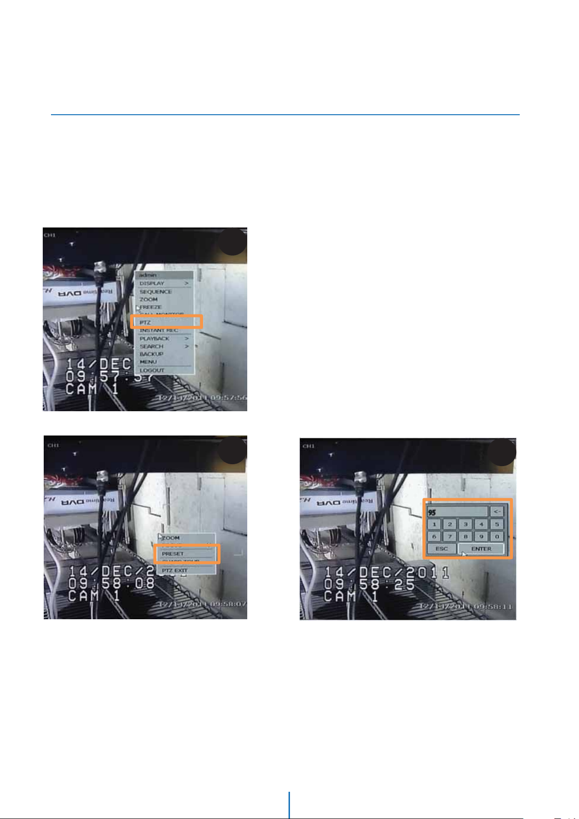
Appendix III
How to Move Around the OSD Menu Using
a USB Mouse
Start OSD Menu
Using the OSD menu, preset, pattern, scan, group, and alarm input function can be configured for each
application.
1. Select Full Screen view on the selected PTZ camera
2. Right-Click the screen & Select ‘PTZ’
3. Right-Click the screen again, & select ‘Preset’
4. Enter 95 to access the OSD menu
2
3
4
54
Page 55

Appendix III
How to Move Around the OSD Menu Using
a USB Mouse
5. Using the mouse, click on the are of the screen labeled:
UP: to scroll up the menu
DOWN: to scroll down the menu
Left: Vertically move from one edit tab to the one to its left
RIGHT: Vertically move from one edit tab to the one to its right.
6. Using the mouse’s wheel, move:
Forward: to save changes and enter from the Root menu to a sub-menu
Backwards: to cancel changes and exit a sub-menu back to the Root menu
Le
Up
Down
5
Right
6
Note: to enter a sub-menu or edit mode, be sure our USB mouse is set to “FOCUS” on the
DVR’s options.To do so, right click on the screen, and select Focus from the pop-up menu.
55
Page 56

Appendix III
How to Move Around the OSD Menu Using
a USB Mouse
To move to a sub-menu
1. Click on the top/bottom of the screen to select the desired sub-menu from the list.
2. Once you have selected the sub-menu you want to enter, scroll the mouse’s wheel forward
To exit a sub-menu
3. When you have completed all desired modifications, scroll the mouse’s wheel backwards to return to the Root menu.
1
2
3
56
Page 57

Appendix III
How to Move Around the OSD Menu Using
a USB Mouse
To move between input tabs
1. Using previous instructions, select the sub-menu and category you wish to modify
2. Scroll the mouse’s wheel forward to enter edit mode
3. The system will show it is in edit mode by highlighting the first tab
1
2
3
57
Page 58

Appendix III
How to Move Around the OSD Menu Using
a USB Mouse
4. Click on the top/bottom of the screen to increase/reduce the values of the data you are modifying
5. When you have completed modifying the first data tab, click on the left side of the screen to move to the next data tab.
6. The system will show it is in edit mode by highlighting the second tab
Repeat as necessary
7. When editing is complete, scroll the mouse’s wheel forward to save all changes, or backwards to cancel all changes.
4
5
6
7
58
Page 59

Appendix IV
How to Move Around the OSD Menu Using
DW-KB100 Joystick Keyboard
Note: Please consult your Joystick Controller’s manual for additional information and
instructions.
59
Page 60

5436 W Crenshaw St. Tampa, FL 33634
Tel : 866-446-3595 / 813-888-9555
Fax : 813-888-9262
www.Digital-Watchdog.com
technicalsupport@dwcc.tv
Technical Support Hours : Monday-Friday
8:30am to 8:00pm Eastern Time
Correct Disposal of This Product (Waste Electrical & Electronic Equipment)
(Applicable in the European Union and other European countries with separate collection systems)
This marking on the product, accessories or literature indicates that the product and its electronic accessories (e.g. charger,
headset, USB cable) should not be disposed of with other household waste at the end of their working life. To prevent
possible harm to the environment or human health from uncontrolled waste disposal, please separate these items from
other types of waste and recycle them responsibly to promote the sustainable reuse of material resources.
Household users should contact either the retailer where they purchased this product, or their local government oce,
for details of where and how they can take these items for environmentally safe recycling.
Business users should contact their supplier and check the terms and conditions of the purchase contract.
This product and its electronic accessories should not be mixed with other commercial wastes for disposal.
 Loading...