

Page 1

INSTRUCTION MANUAL
DWC-PTZ10x
Mini SPEED DOME CAMERA
Page 2
]
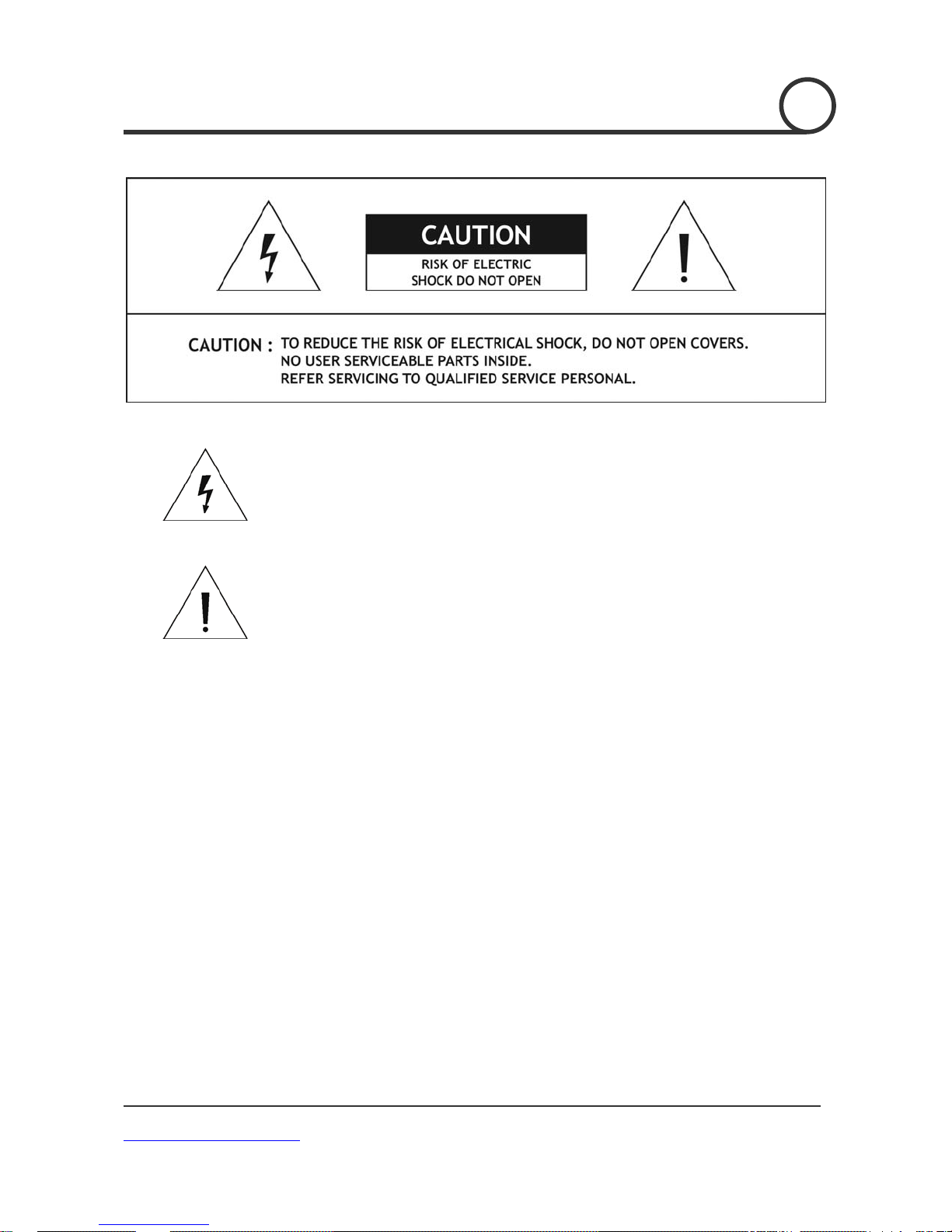
This lightn ing flash with arrowhe ad symbol is intend ed to alert the user to
the presence of un-insulated "dangerous voltage" within the product's
enclosure that m ay be of suff icient mag nitude to co nstitute a r isk of electri c
shock to individuals.
This exclamation point symbol is intended to alert the user of the presence
of important operating and maintenance (servicing) instructions in the
literature accompanying the appliance.
DWC-PTZ10x [Mini SPEED DOME CAMERA
www.Digital-Watchdog.com
2/49
Page 3
]
NOTICE
1. Read Instructions
Read all of the safety and operating instructions before using the product.
2. Retain Instructions
Save these instructions for future reference.
3. Attachments/ Accessories
Do not use attachments or accessories unless recommended by the manufacturer as they may cause
hazards, damage product and void warranty.
4. Water and Moisture
Do not use this product near water or moisture. (Indoor Version)
5. Installation
Do not place or mount this product in or on an unstable or improperly supported location.
Improperly installed product may fall, causing serious injury to a child or adult, and damage to the
product. Use only with a mounting device recommended by the manufacturer, or sold with the
product. To insure proper mounting, follow the manufacturer's instructions and use only mounting
accessories recommended by manufacturer.
6. Power source
This product should be operated only from the type of power source indicated on the marking label.
Important Safeguard
Operating
Before using, make sure power supply is properly connected.
While operating, if any abnormal condition or malfunction is observed, stop using the camera
Handling
Do not disassemble or tamper with parts inside the camera.
Do not drop or subject the camera to shock and vibration as this can damage camera.
Care must be taken when you clean the clear dome cover. Scratches and dust will ruin your
Installation and Storage
Do not install the camera in areas that exceed the allowable temperature range. (Indoor Version)
Avoid installing in humid or dusty places (Indoor Version)
Avoid installing in places where radiation is present.
Avoid installing in places where there are strong magnetic fields and electric signals.
Avoid installing in places where the camera would be subject to strong vibrations.
Never expose the indoor version camera to rain and water.
Precautions
immediately and then contact your dealer.
quality of the picture.
DWC-PTZ10x [Mini SPEED DOME CAMERA
www.Digital-Watchdog.com
3/49
Page 4

]
1
○
Introduction
Features 5
Product & Accessories
Parts & Functions
2
○
Installation
DIP Switch Setup 9
Direct Installation on the Ceiling
Installation using Flush Mount Ring Bracket
Installation using Ceiling Mount Bracket
Installation using Wall Mount Bracket
Cabling 15
3
○
Operation
Checking Before Operation 17
Preset and Pattern Function Pre-Check
Start OSD Menu
Reserved Preset
Preset
Group
Pattern
Group
Schedule
Other Functions
OSD Display of Main Screen
CONTENTS
18
18
19
19
20
21
22
23
24
7
8
11
12
13
14
17
DWC-PTZ10x [Mini SPEED DOME CAMERA
www.Digital-Watchdog.com
4
○
How to use OSD Menu
General Rules of Menu Operation 25
Main Menu
Display Setup
Privacy Zone Mask Setup
Motion Setup
Function Setup
Preset Setup
Group Setup
Pattern Setup
Group Setup
Schedule Setup 37
Camera Setup
System Setup
System Initialize
5
○
Specifications
Dimension
25
26
27
28
30
31
33
34
35
38
40
41
42
43
4/49
Page 5

]
INTRODUCTION
1
Camera Specifications
Features
Sensor: ¼“ Super-HAD II CCD
520TVL [Color] 570TVL
Lens: 10x Digital, 10x Optical Zoom (3.8 ~38mm)
360 Continuous Pan Rotation
SSNR Digital Noise Reduction
Zoom Magnification: 10 Optical Zoom, 10 Digital Zoom (Max 100 Zoom) [To be Delete]
Function: True Day & Night Function (Moving IR Cut Filter)
Focus Mode: Auto / Manual / Semi-Auto
Auto Sensing, Multiprotocol Receiver
Multi-language Menu-Setup: [English / Spanish / Portuguese / French / Italian / Polish
/Dutch]
Independent or General Camera Characteristic Setup in Preset operation
24VAC/12VDC Power Input
Powerful Pan/Tilt Functions
Max. 360/sec high speed Pan/Tilt Motion
Using Vector Drive Technology, Pan/Tilt movements are accomplished using the shortest
path theory. As a result, time to target view is reduced dramatically and the video on the
monitor is very natural to watch.
For jog operation using a controller, since ultra slow speed 0.05/sec can be reached, it is
very easy to p osition the camera to the desired target view.
Proportional Pan/Tilt automatically reduces or increases the pan/tilt speed in proportion to
the mount of zoom. At telephoto zoom settings, the pan/tilt speeds will be slower for a given
amount of joystick deflection than at wide zoom settings. This function keeps the image
from moving too fast on the monitor when there is a large amount of zoom
Preset, Pattern, Scan, Group, Privacy Mask, Schedule and More…
127 Presets are assignable and characteristics of each preset can be set up independently,
such as White Balance, Auto Exposure, Label and so on.
8 Scans can be stored. This enables to move camera repetitively between two preset positions
at designated speeds.
4 Pattern are memorized to repeat a series of Pan/Tilt, Zoom, and Preset functions that can
be recalled with a command or automatically by a programmed function (Alarm, Schedule, or
Power-Up)
DWC-PTZ10x [Mini SPEED DOME CAMERA
www.Digital-Watchdog.com
5/49
Page 6

]
8 Groups are memorized to repeat a series of Presets, Patterns, and Scans. Each group can be
stored 20 entities of Preset/Pattern/Group functions. This function enables the dome camera
to move in comb i nations of th os e functions re petitively .
4 Privacy Zone Masks can be programmed. The Masked Zones can be set anywhe re in the
viewing area and can be any size.
7 Schedules can be assigned by day and time. Appropriate actions (such as Home, Preset,
Group, Pattern, Scan) can be defined for each rule. Also, it is possible to schedule these
customer settings by daily and weekly requirements.
PTZ (Pan/Tilt/Zoom) Control
RS-485 control, max. 256 cameras can be controlled at the same time. [To Be Delete]
Pelco-D/ Pelco-P /Samsung protocol can be selected as a control protocol in the current
version of firmware. (Using the small Dip-switch at the back of the dome camera)
DWC-PTZ10x [Mini SPEED DOME CAMERA
www.Digital-Watchdog.com
6/49
Page 7

]
OSD (On Screen Display) Menu
OSD menu is provided to display the status of camera and to configure the functions
interactively.
There are currently 7 Languages that are supported in the OSD Menu:
[ENGLISH/ESPAÑOL/FRANÇAIS/DEUTSCH/ITALIANO/РУССКИЙ/PORTUGUÊS]
The information such as Camera ID, Pan/Tilt/Zoom/Direction, and Alarm Input & Output,
date/time, current temperature and Preset can be displayed on screen.
Each display item can be turned On or Off independently.
Alarm I/O Functions
2 alarm sensor Inputs and 1 relay output are available.
To protect from external electric noise and shock, the alarm sensor Input is decoupled by
using photo coupler diode.
If an external sensor is activated, camera can be set to move to the corresponding Preset
position.
Relay output can be assigned to work with a certain preset.
INTRODUCTION
1
Reserved Presets for Special Purpose
In addition to the standard 127 presets, direct calling of reserved presets allows users to set
up many of th e camera functions wi th or without using OSD menu. For more inf ormation,
refer to “Reserved Preset” in this manual.
In addition to 127 Presets from 1 to 128 can be assigned excluding preset 95 is reserved for
Main Menu Setup
DWC-PTZ10x [Mini SPEED DOME CAMERA
www.Digital-Watchdog.com
7/49
Page 8
]
INTRODUCTION
INTRODUCTION
1
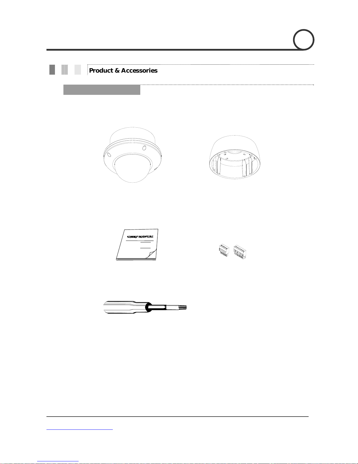
Main Product & Accessories
Accessory
Product & Accessories
Main Body Surface Mount Bracket
Manual Terminal Block
Torque Screw Driver
DWC-PTZ10x [Mini SPEED DOME CAMERA
www.Digital-Watchdog.com
8/49
Page 9
]
INTRODUCTION
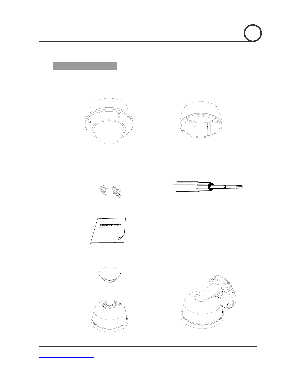
Main Product
Main Body Sun Shield Housing
Accessory
1
Options
Terminal Block Torque Screw Driver
Manual
Pendant Mount Bracket Wall Mount Bracket
DWC-PTZ10x [Mini SPEED DOME CAMERA
www.Digital-Watchdog.com
9/49
Page 10
]
INTRODUCTION
1
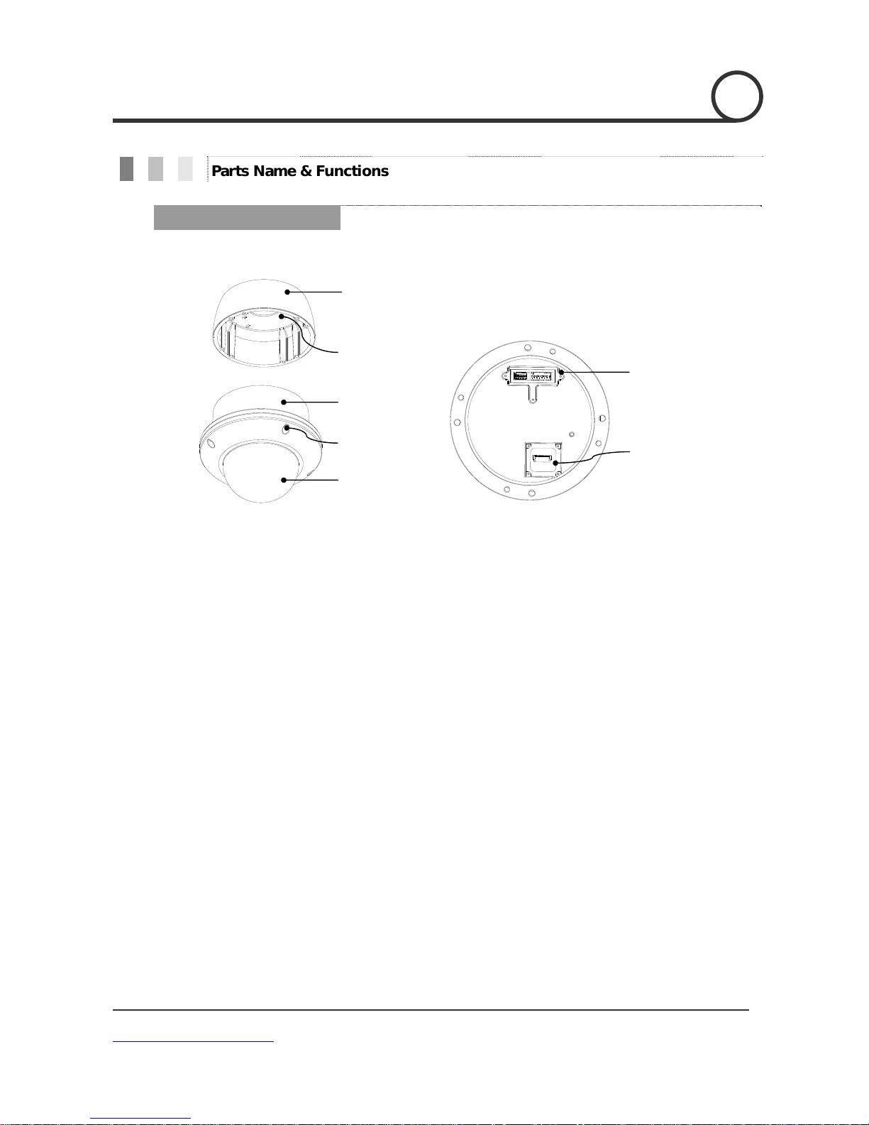
Parts Name & Functions
Surface
Mount Bracket
Mounting Hole
Main Body
Lockup Screw
Dome Cover
Main Unit / Surface Mount Bracket Back of Main Unit
Prototol&Braud-rate
Dip switches
Cabling
Ter m in al B la c k
Surface Mount Bracket This is used to install the camera directly on the ceiling. After
separating the cover attach this directly to ceiling. Camera must be
assembled at the last stage.
Do not use this bracket when installing camera on the wall with
wall mount bracket or on the ceiling with ceiling mount bracket.
Separating Slit Using a coin, you can separate upper part lower body of the dome.
Dome Cover Do not detach protective vinyl from dome cover before finishing
the installation process to protect dome cover from scratches or
dust.
DIP Switch Adjusts camera ID and pr oto c o ls.
Cable Duct When you want to install the camera on the surface of hard ceiling,
you need to handle the cable through side of the dome. In this
case, break t he side wall bit and feed the cable through th e cable
duct.
DWC-PTZ10x [Mini SPEED DOME CAMERA
www.Digital-Watchdog.com
10/49
Page 11
]
INSTALLATION
2
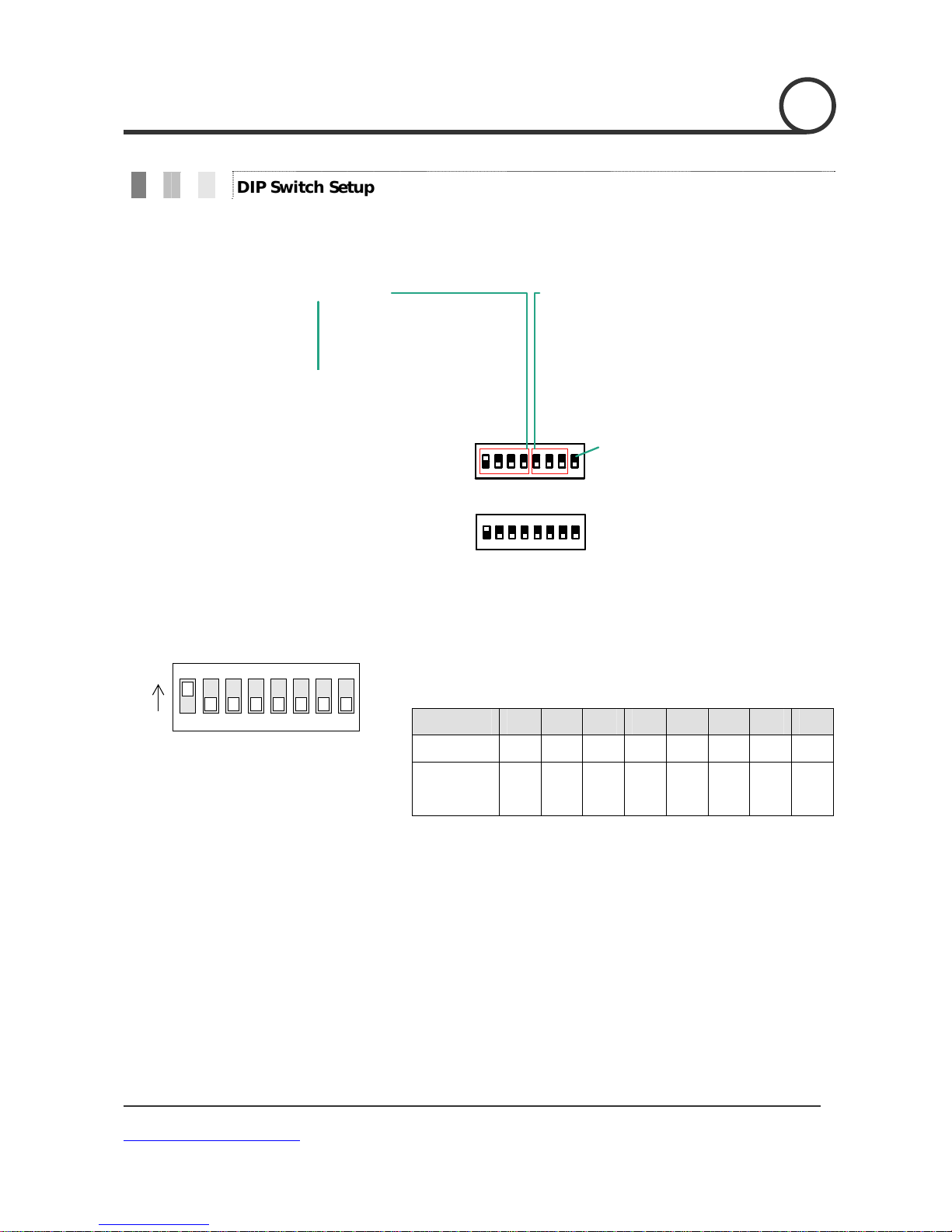
DIP Switch Setup
Before you install the camera, you should set the DIP switches to configure the camera ID, Baud rate,
and communication protocol.
Protocol
0x00 : Auto Select
0x01 : Pelco-D
0x02 : Pelco-P
0x03 : SAMSUNG
0x04 : VCLTP
0x05 : KD6
Buad Rate
0x00 : 2400
0x01 : 4800
0x02 : 9600
0x03 : 19200
0x04 : 38400
RS-485
Terminate
ID Setting (1~255)
Camera ID Setup
ON
ON
123456
78
ID number of camera is set using binary number. The example
is shown below.
SW 1 2 3 4 5 6 7 8
ID Value 1 2 4 8 16 32 64 128
ex) ID=5 on off on off off off off off
ex) ID=10 off on off on off off off off
The range of ID is 0~255. Factory default of Camera ID is 1.
If you want to control a certain camera, you must match the
camera ID with Cam ID setting of DVR or Controller.
DWC-PTZ10x [Mini SPEED DOME CAMERA
www.Digital-Watchdog.com
11/49
Page 12
]
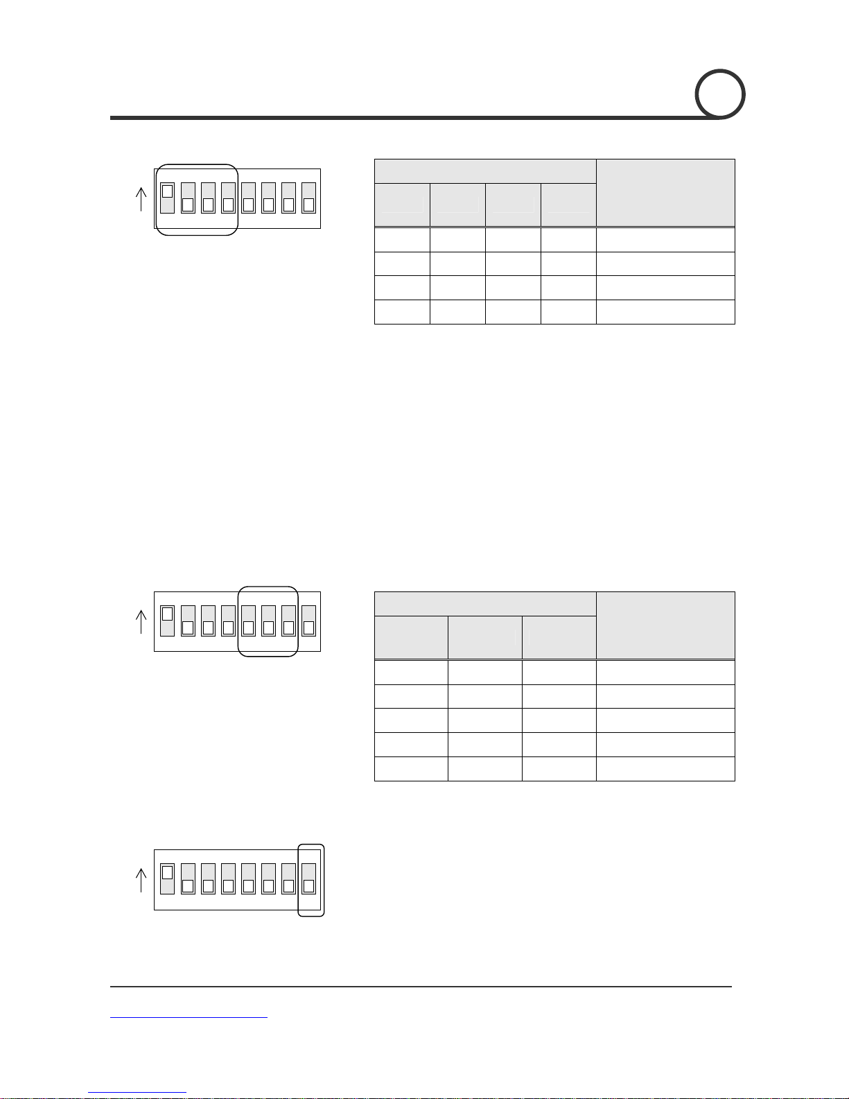
INSTALLATION
2
Communication Protocol Setup
ON
ON
123456
78
Communication Baud rate Setup
ON
ON
123456
78
RS-485 Termination Resistor
ON
ON
123456
RS-485 Termination Resistor (On/Off)
78
Select the appropriate Protocol with DIP switch combination.
Switch State
SW-1 SW-2 SW-3 Sw-4
Protocol
OFF OFF OFF OFF Auto Protocol
ON OFF OFF OFF PELCO-D
OFF ON OFF OFF PELCO-P
ON ON OFF OFF SAMSUNG
If you set the protocol as Auto Protocol, camera will
automatically recognize the type of Protocol.
Auto Protocol supports Pelco-D and Samsung Protocol.
If you want to control using DVR or system keyboard, their
protocol must be identical to camera. Otherwise, you cannot
control the camera.
If you changed camera protocol by changing DIP S/W, the
change will be effective after you reboot the camera.
Factory default of protocol is “Auto Protocol”
Select the appropriate Baud rate with DIP switch combination.
Switch State
Factory default of Baud rate is “9600 BPS”
Pin 8 is used for ON/OFF of RS-485 Termination. Normally, it
SW-5 SW-6 SW-7
OFF OFF OFF 2400 BPS
ON OFF OFF 4800 BPS
OFF ON OFF 9600 BPS
ON ON OFF 19200 BPS
OFF OFF ON 38400 BPS
must be OFF state. Especially when you have trouble with long
Daisy chain style connection, turn ON this termination switch of
last camera.
Pin 8
Protocol
DWC-PTZ10x [Mini SPEED DOME CAMERA
www.Digital-Watchdog.com
12/49
Page 13
]
INSTALLATION
2
In ceiling mount
Installation using Surface mount on the Ceiling
1. Pass the cables from the camera unit through the
ceiling mount bracket. Then, connect video,
communication, and power cables.
2. Install surface mount bracket to the ceiling using the
four screws.
3. Align the four screw hole s in the camera unit with the
screw holes in the ceiling mount bracket. Then, secure
the camera in place by tightening the four screws.
4. Carry out the settings and adjustments for the
camera.
5. Secure the dome cover by tightening with screws.
DWC-PTZ10x [Mini SPEED DOME CAMERA
www.Digital-Watchdog.com
13/49
Page 14
]
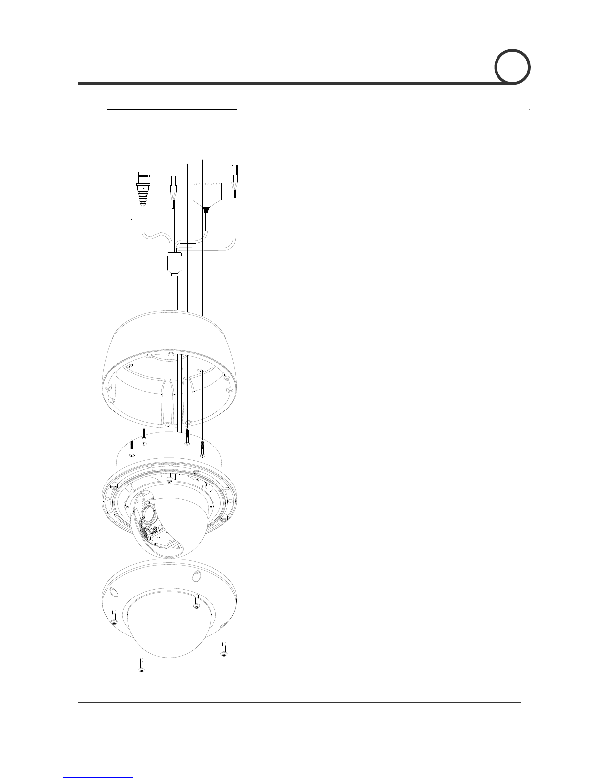
INSTALLATION
Surface mount
1. Pass the cables from the camera unit through surface
mount bracket.
Then connect Video, communication, and power cables.
2. Install surface mount bracket to the ceiling usingthe
four screws.
3. Align the four screw holes in the camera unit with the
screw holes in the Surface mount bracket.
Then, secure the camera in place by tightening the
four screws.
4. Carry out the settings and adjustments for the camera.
5. Secure the dome cover by tightening with screws.
DWC-PTZ10x [Mini SPEED DOME CAMERA
www.Digital-Watchdog.com
14/49
Page 15
]
INSTALLATIONINSTALLATION
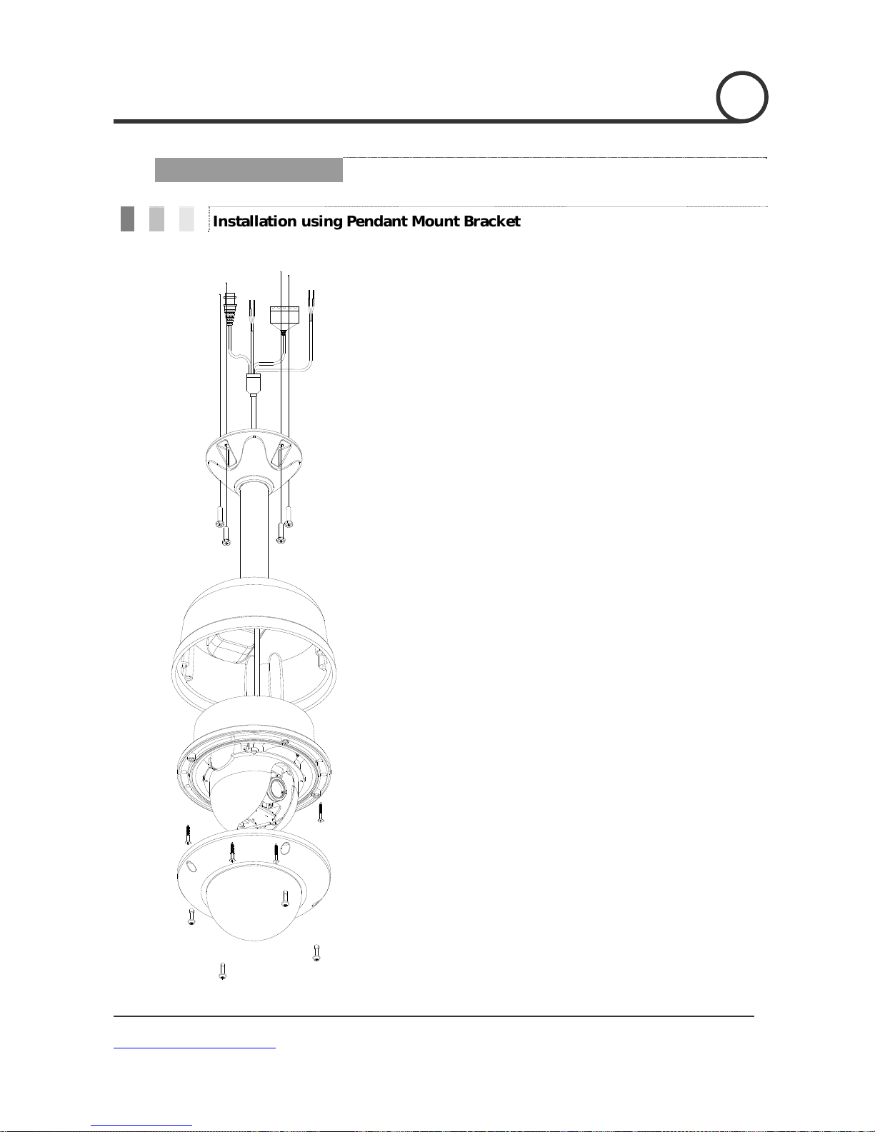
Installation using Pendant Mount Bracket
1. Pass the cables from the camera unit through the pendant
mount bracket.
Then connect Video, communication, and power cables.
2. Install pendant mount bracket to the ceiling using the four screws.
3. Align the four screw holes in the camera unit with the screw
holes in the Pendant mount bracket.
Then secure the camera in place by tightening the four screws.
4. Carry out the settings and adjustments for the camera.
5. Secure the dome cover by tightening with screws.
DWC-PTZ10x [Mini SPEED DOME CAMERA
www.Digital-Watchdog.com
15/49
Page 16

]
INSTALLATION
2
Installation using Wall Mount Bracket
DWC-PTZ10x [Mini SPEED DOME CAMERA
www.Digital-Watchdog.com
1. Pass the cables from the camera unit through the wall
mount bracket.
Then connect Video, communication, and power cables.
2. Install wall mount bracket on the wall using the four screws.
3. Attach the main unit to the wall mount bracket with the four
screws.
4. Carry out the settings and adjustments for the camera.
5. Secure the dome cover by tightening with the screws.
16/49
Page 17

]
INSTALLATION 2
Cabling
VIDEO(YELLOW)
POWER I
N
VCC(RED
)G
ND(BLACK)
SOLDERING
ALARM CABLE
RS485
D+(BLACK)
D-(WHITE)
Dual Voltage
Dual Voltage
DC12V/AC24V
DC12V/AC24V
BNC Video
BNC Video
RS-485
RS-485
D-
DD+
D+
1 (Black): SENSOR COM
1 (Black): IN-COM
1 (Black): IN-COM
2 (Yellow): IN1
2 (Yellow): IN1
2 (Brown): SENSOR1
3 (Brown): IN2
3 (Brown): IN2
3 (Red): SENSOR2
4 (Orange): Relay COM
4 (Red): Relay Out
4 (Red): Relay Out
5 (Orange): Relay O ut
5 (Orange): Relay O ut
5 (Yellow): Relay NO
Controller/DVR
Controller/DVR
Monitor
MonitorMonitor
Sensors
Sensors
Relay Out
Relay Out
Dual Voltage
Dual Voltage
DC12V/AC24V
DC12V/AC24V
Controller/DVR
Controller/DVR
BNC Video
BNC Video
Monitor
MonitorMonitor
DWC-PTZ10x [Mini SPEED DOME CAMERA
www.Digital-Watchdog.com
PWR(+)
PWR(+)
PWR(-)
PWR(-)
SENSOR COM
IN COM
F.G
F.G
RS-485(+)
RS-485(+)
RS-485(-)
RS-485(-)
VIDEO(+)
VIDEO(+)
VIDEO(-)
VIDEO(-)
Cabling Termina l Block
Cabling Termina l Block
IN COM
SENSOR1
IN1
IN1
SENSOR2
IN2
IN2
Relay Out
Relay Out
Relay CO M
Relay Out
Relay Out
Relay NO
Sensors
Sensors
Relay Out
Relay Out
17/49
Page 18

]
INSTALLATION 2
Power Connection
Please, check the voltage and current capacity of rated power carefully. Rated power is indicated
in the back of main unit.
Power Consumption
Power Mode Input Voltage Range
DC 12V DC 11V ~ 24V 14 W(MAX) 26W(MAX)
AC 24V AC 20V ~ 28V 9W(MAX) 23W(MAX)
While in Normal
operation
While Heater
in operation
RS-485 Communication
For PTZ control, connect this line to keyboard and DVR. To control multiple cameras at the same
time, RS-485 communication lines are connected in parallel as shown below.
DWC-PTZ10x [Mini SPEED DOME CAMERA
www.Digital-Watchdog.com
18/49
Page 19

]
Video Connection
Connect with BNC coaxial cable.
Alarm Input Co n nection
Sensor Input
INTERNAL
SENSOR1
SENSOR2
SENSOR COM
INSTALLATION
It is noted that short circuit between GND and Input pin means alarm activation.
If you want to use Alarm Input, the types of sensor must be selected in OSD menu. The sensor
types are Normally Open and Normally Closed. If sensor typ e is not set prop erly, the ala rm can
be activated reverse ly.
2
Normally Open (N.O) Sensor output is turned ON when sensor is activated
Normally Closed (N.C) Sensor output is turned OFF when sensor is activated
Relay Output
Relay COM
Relay NO
There are 4 Alarm Outputs and all of them are Relay contact type. Therefore, you do
not have to care about polarity, AC/DC, and isolations between channels. Care must be
taken to connect relay power as shown above.
DWC-PTZ10x [Mini SPEED DOME CAMERA
www.Digital-Watchdog.com
19/49
Page 20

]
OPERATION
3
Check Points Before Operation
Before power is connected, please check the cables carefully.
The camera ID of the controller must be identical to that of the camera to be controlled. The camera
ID can be checked in the System Information screen of the OSD Menu.
If your controller supports multi-protocols, the protocol must be changed to match the camera.
If you changed camera protocol by changing DIP switch, the change will be effective after you reboot
the camera.
Since the operation method can be different for each controller available, refer to the manual for
your controller if camera can not be controlled properly.
Preset and Pattern Function Pre-Check
Review Operating instructions for Preset, Group, Scan and Pattern function programming with
controller or DVR prior to using camera. (refer to your System keyboard Manual)
If controller or DVR has no pattern button or function, use shortcut keys with preset numbers. For
more information, refer to “Reserved Preset” in this manual.
DWC-PTZ10x [Mini SPEED DOME CAMERA
www.Digital-Watchdog.com
20/49
Page 21

]
OPERATION
3
Starting OSD Menu
Function Using the OSD menu, Preset, Pattern, Scan, Group and Alarm Input function as
well as various detail camera settings can be configured in an interactive manner.
Enter Menu
<Go Preset> [95]
Reserved Preset
Description Some Preset numbers are reserved for direct access to specific functions in OSD
menu. These direct commands via preset provide quick execution of various
functions using keyboard controller as well as simplifying the interface between
DVR and IP equipments.
Function <Go Preset> [95] : Enters into OSD menu
<Go Preset> [131~134] : Runs Pattern Function 1 ~ 4
<Go Preset> [141~148] : Runs Scan Function 1 ~ 8
<Go Preset> [151~158] : Runs Group Function 1 ~ 8
<Go Preset> [161] : Sets Relay Output to OFF
<Set Preset> [161] : Sets Relay Output to ON
<Go Preset> [170] : Sets Camera BLC Mode to OFF
<Go Preset> [171] : Sets Camera BLC Mode to HIGH
<Go Preset> [174] : Sets Camera Focus Mode to AUTO
<Go Preset> [175] : Sets Camera Focus Mode to Manual
<Go Preset> [176] : Sets Camera Focus Mode to SEMI-AUTO
<Go Preset> [177] : Sets Day & Night Mode to AUTO
<Go Preset> [178] : Sets Day & Night Mode to NIGHT
<Go Preset> [179] : Sets Day & Night Mode to DAY
<Go Preset> [190] : Sets OSD Display Mode to AUTO (Except Privacy Mask)
<Go Preset> [191] : Sets OSD Display Mode to OFF (Except Privacy Mask)
<Go Preset> [192] : Setting OSD Display Mode to ON (Except Privacy Mask)
<Go Preset> [193] : Sets all Privacy Mask Display to OFF
<Go Preset> [194] : Sets all Privacy Mask Display to ON
<Go Preset> [167] :
<Set Preset>[167] :
<Go Preset> [195] : Heater ON (Turn off after 5mins and switch to Auto
Zoom Proportional Jog ON
Zoom Proportional Jog OFF
mode)
DWC-PTZ10x [Mini SPEED DOME CAMERA
www.Digital-Watchdog.com
21/49
Page 22

]
<Go Preset> [196] : Heater OFF (Turn off and switch to Manual mode)
<Go Preset> [197] : Fan ON (Turn off after 5mins and switch to Auto mode)
<Go Preset> [198] : Fan OFF (Turn off and switch to Manual mode)
<Go Preset>[200] : Digital Zoom ON
<Go Preset>[201] : Digital Zoom OFF
OPERATION
3
DWC-PTZ10x [Mini SPEED DOME CAMERA
www.Digital-Watchdog.com
22/49
Page 23

]
OPERATION
3
Preset
Function Max. 127 positions can be stored as Preset positions. The Preset number can be
assigned from 1 to 128. It is noted that preset “95” is reserved for starting OSD
menu.
Camera characteristics (i.e. White Balance, Auto Exposure) can be set up
independently for each preset and they are adjusted by using OSD menu. Four
relay outputs can be controlled in conjunction with one Preset.
Set Preset <Set Preset> [1~128]
Run Preset <Go Preset> [1~128]
Delete Preset To delete Preset, use OSD menu.
Scan
Function By using Scan function, you can make the c amera move between 2 Preset positions
repeatedly. When Scan function runs, the camera moves from the preset assigned as
the 1st point to the preset assigned as the 2nd point in a CW(Clockwise) direction.
Then camera moves from the preset assigned as the 2nd point to the preset assigned
as the 1st point in a CCW(Counterclockwise) direction.
In a case where the preset assigned as the 1st point is the same as the preset
assigned as the 2nd point, camera turns on its axis 360 in a CW(Clockwise) direction
and then it turns on its axis 360 in a CCW(Counterclockwise) direction.
Speed can be set up from 1/sec to 180/sec.
Set Scan To set Scan, use OSD menu.
Run Scan Method1) <Run Scan> [Scan NO.] [Enter]
Method2) <Go Preset> [Scan NO.+140] ex) Run Scan 2 : <Go Preset> [142]
Delete Scan To delete Scan, use OSD menu.
DWC-PTZ10x [Mini SPEED DOME CAMERA
www.Digital-Watchdog.com
23/49
Page 24

]
OPERATION
3
Pattern
Function Pattern Function enables the camera to memorize the path (mostly curve path)
created by keyboard controller. By running the pattern, the memorized path can
be reconstructed exactly as memorized whenever required.
4 Patterns are available and Maximum 1000 communication commands can be
stored in a pattern.
Set Pattern Pattern can be created by one of the following two methods.
Method 1) <Set Pattern> [Pattern NO.]
Pattern editing screen is displayed as below.
Movement by Joystick and preset movement can be memorized in a
The available memory size is displayed in progress bar.
To save the recording, press NEAR key and to cancel, press FAR key.
Method 2) OSD Using OSD Menu: See the section “How to use OSD Menu”.
pattern.
Run Pattern M e t ho d 1) <Run Pattern> [Pattern NO.]
Method 2) <Go Preset> [Pattern
NO.+130]
Delete Pattern Use OSD menu to delete a Pattern.
When the pattern is saved or executed, the PAN/TILT is operated with Auto Flip OFF mode.
DWC-PTZ10x [Mini SPEED DOME CAMERA
www.Digital-Watchdog.com
ex) Run Pattern 2 : <Run Pattern> [2]
ex) Run Pattern 2: <Go Preset> [132]
24/49
Page 25

]
OPERATION
3
Group
Function The Group function allows camera to run in a sequence of Presets, Patterns
and/or Scans. Max 8 Group can be stored. Each Group can have max 20 action
entities wh ich ca n be pres et, pa ttern or Scan. D well t ime mea ns the time in terva l
between actions and is adjustable in the menu. Additionally, there is an option
number with which Preset speed as well as the repetition number of Pattern and
Scan can be set.
Dwell Time
Preset 1 Pattern 5
Max 20 entities
Auto pan
8
Set Group Use OSD Menu to create a Group.
Run Group Method1) <Run Pattern> [Group
NO.+20]
Method2) <Go Preset> [Group
NO.+150]
Delete Group Use OSD Menu to delete.
ex) Run Group 7 : <Run Pattern> [27]
ex) Run Group 7 : <Go Preset> [157]
DWC-PTZ10x [Mini SPEED DOME CAMERA
www.Digital-Watchdog.com
25/49
Page 26

]
OPERATION
3
Function The Schedule function allows running an appropriate function like Preset, Scan,
Set Schedule Use OSD Menu to create a Schedule
Run Schedule Use OSD Menu of Schedule Master
Delete Schedule Use OSD Menu to Delete.
Schedule
Group, Pattern, Home move at a designated day and time. For example, if you
setup a rule Tuesday at 9:00AM and Preset 1 (say Main Gate), the camera will
move to Main Gate every Tuesday at 9:00AM. If you choose Weekday, camera will
move to Main Gate every day except the weekend.
It is noted that due to the r e a l ti me clock, the ti m e data will be k ep t r e g ardless of
blackout. The initial time and day setup is essential for proper Schedule
function.
Enable
DWC-PTZ10x [Mini SPEED DOME CAMERA
www.Digital-Watchdog.com
26/49
Page 27

]
OPERATION
3
Other Functions
Preset Lock This function is made to protect preset data from unauthorized overwriting. If
Preset Lock is ON, Preset save command using Hot Key is disabled while saving a
Preset via the OSD Menu is acceptable.
Power Up Action
This function enables the camera to resume programmed actions such
as preset, Pattern, and Scan when the power been cycled
Auto Flip In case the tilt angle arrives at the top of tilt orbit (83°), the zoom module
camera keeps moving to opposite tilt direction (180°) to keep tracing targets. As
soon as the zoom module camera passes through the top of tilt direction (83°),
images should be reversed automatically and F appears in screen. If this function
is set to OFF, tilt movement range is 0 ~ 95°.
Par king Actio n Thi s function enable s the camera to park in a specific posit ion automatical ly if
operator doesn’t operate the controller for a while. The Park Time can be defined
as an interval from 1 minute to 4 hours.
Alarm Input 2 Alarm Inputs are available. If an external sensor is activated, camera can be set
to move to corresponding preset position. It is noted that the latest alarm input
is effective if multiple sensors are activated.
Privacy Zone Mask To protect privacy, MAX. 4 Privacy Masks can be created in arbitrary positions to
hide objects such as windows, shops or private house. With a Spherical
Coordinates system, powerful Privacy Zone Mask function is possible.
GENERAL/SPECIAL
Image Setup
Semi Auto Focus
DWC-PTZ10x [Mini SPEED DOME CAMERA
www.Digital-Watchdog.com
WB(White Balance) and AE(Auto Exposure) can be set up independently for each
preset. There are 2 modes, "General" mode & "Special" mode. The General mode
means that W B or AE can be set up completely and simultane o u sly for all presets
in "ZOOM CAMERA SETUP" menu. The Special mode means that WB or AE can
only be set up independently or separately for each preset in each preset setup
menu. Each Special WB/AE value should activate correspondingly when camera
arrives at each preset location.
During jog operation, General WB/AE value should be applied. All Special WB/AE
value will not be changed regardless of General WB/AE value change.
This mode enables the camera to switch focus mode automatically operation by
operation. Manual focus mode is selected during preset operation and Auto
focus mode is recovered if jog operation is started. During Preset action, instead
of auto focusing, manual focus data stored when it is created will be applied as
soon as camera arrives to the preset. This is helpful to get well-focused image in
a short time.
27/49
Page 28

]
OPERATION
3
OSD Display of Main Screen
P/T/Z Current Pan/Tilt angle in degree, zoom magnification and a compass direction.
Camera ID Current Camera ID(Address).
Action Title The followings are possible Action Titles and their meanings.
"SET PRESET " When Preset is stored
"PRESET " When camera reaches Preset
"PATTERN " When Pattern is in action
"AUP/PRESET " When Group is in action
"UNDEFINED" When undefined function is called to run
Preset Label The Label stored for specific Preset.
Alarm
Information
Image Flip Shows that images are currently reversed by Auto Flip Function.
Temperature Current Temperature: Boxed “C” and “F” means Celsius and Fahrenheit
Date/Time Displays Current Date and Time.
This information shows the current state of the Alarm Input. The “I” means
Input and “O” is outpu t. If an Input i s in the ON state it will show the number of
the input. If an Input is in the OFF state, '-' will be displayed. In the same way
“O:1” means output 1 is ON “O:-“ is OFF.
Ex) When Point 2 of inputs are ON, and Output 1 is On, OSD will show as below
DWC-PTZ10x [Mini SPEED DOME CAMERA
www.Digital-Watchdog.com
28/49
Page 29

]
HOW TO USE OSD MENU
4
General Rules of Key Operation for Menu
The menu item enclosed with < > always means it has a sub menu.
For all menu levels, to go into sub menu, press NEAR key.
To go up one menu level, press FAR key.
To move from item to item in the menu, use joystick in the Up/Down or Left/Right directions.
To change a value of an item, use Up/Down of the joystick on the controller.
Press NEAR key to save values and Press FAR key to cancel values.
Main Menu
System Information Shows System information such as current
firmware version and communication
settings.
Display Setup Enable/Disable OSD display on Main Screen.
Motion Setup Setup for motion related settings.
Function Setup Setup for various functions such as Preset,
Auto Pan, Pattern, Scan and Schedule.
Camera Setup Configure Camera related functions and
data.
System Setup Configure for Basic system setup.
System Initialize Initializes system configuration and sets all
DWC-PTZ10x [Mini SPEED DOME CAMERA
www.Digital-Watchdog.com
29/49
Page 30

]
/
HOW TO USE OSD MENU
4
System Information
SYSTEM INFORMATION
-------------------------FIRMWARE VER 1.02S0
COLOR SYSTEM NTSC
PROTOCOL SAMSUNG
BAUD RATE 9600
ADDRESS 255
BACK
EXIT
Display Setup
DISPLAY SETUP
--------------------------
CAMERA ID ON
PTZ INFORMATION AUTO
ACTION TITLE AUTO
RESET LABEL AUTO
ALARM I
DATE/TIME ON
TEMERATURE CELSIUS
<PRIVACY ZONE>
BACK
EXIT
O AUTO
Firmware Ver. Shows current firmware version of camera.
Color System Shows current analog video system of the
Protocol Shows current Protocol for PTZ control
Baud Rate Shows current Baud Rate of PTZ control.
Address Shows current Camera ID for PTZ control.
This menu defines Enable/Disable of OSD display on Main Screen.
If an item is set to be AUTO, the item is displayed only when the
value of it is changed.
Camera ID [ON/OFF]
PTZ Information [ON/OFF/AUTO]
Action Title [ON/OFF/AUTO]
Preset Label [ON/OFF/AUTO]
Alarm I/O [ON/OFF/AUTO]
Date/Time [ON/OFF]
Temperature [CELSIUS/FAHRENHEIT/OFF]
camera.
DWC-PTZ10x [Mini SPEED DOME CAMERA
www.Digital-Watchdog.com
30/49
Page 31

]
[
]
HOW TO USE OSD MENU
4
Privacy Zone Mask Setup
Privacy Zone Area Setup
Privacy Zone Size Adjustment
Select area in image to mask.
Mask No [1~4]
Select Mask number. If the selected mask
already has data, camera moves as it was
set. Otherwise, “UNDEFINED” will be
displayed under “Mask NO”.
Display [ON/OFF]
Defines whether or not camera mask
shows on images.
Clear Mask [CANCEL/OK]
Deletes data in the selected ma s k NO.
Move the came ra to area to be maske d. Then the menu to ad just
mask size will be displayed.
EDIT MASK 1
--------------------------
:ADJUST MASK HEIGHT
[:ADJUST MASK HEIGHT]
[NEAR:SAVE / FAR:CANCEL]
DWC-PTZ10x [Mini SPEED DOME CAMERA
www.Digital-Watchdog.com
Adjust mask size. Use joystick or arrow buttons to adjust mask
size.
(Left/Right) Adjusts mask width.
(Up/Down) Adjusts mask height.
It is noted that during PAN/TILT control li ke jog action, the object
behind the privacy mask can be disclosed for a short period of time.
To hide a certain zone completely regardless of high speed PT motions,
it is recommended that the size of mask must be 20% bigger than original
31/49
Page 32

]
HOW TO USE OSD MENU
4
Motion Setup
MOTION SETUP
--------------------------
PRESET LOCK ON
POWER UP ACTION ON
AUTO FLIP AUTO
JOG MAX SPEED 140/SEC
JOG DIRECTION NORMAL
FRZ IN PRESET OFF
<PARKING ACTION SETUP>
<ALARM INPUT SETUP>
BACK
EXIT
Setup the general functions of Pan/Tilt motions.
Preset Lock [ON/OFF]
This function is made to protect preset
data from unauthorized overwriting. If
Preset Lock is ON, it is impossible to create
and delete Preset, Auto Pan, Pattern and
Scan. It is only possible to run those
functions. To create and delete those
functions, use OSD menu.
Power Up Action [ON/OFF]
Refer to “Other Functions" section.
Auto Flip [ON/OFF]
Refer to “Other Functions" section.
Jog Max Speed [2/sec ~200/sec]
Sets maximum jog speed. Jog speed is
inversely proportional to zoom
magnification. As zoom magnification goes
up, pan/tilt speed goes down.
Jog Direction [INVERSE/NORMAL]
If you set this to ‘Inverse’, the view in
the screen is moving same direction with
jog tilting. If ‘Normal’ is selected, the
view in the screen is moving reversely.
DWC-PTZ10x [Mini SPEED DOME CAMERA
www.Digital-Watchdog.com
Freeze in Preset
This function freezes the preset scene on the
monitor when switching to another preset.
This allows for smooth transition from one
preset scene to another. Preset freeze also
reduces bandwidth when used with digital
network systems such, and guarantees that
blanked areas will not be revealed when
going to a preset.
32/49
Page 33

]
HOW TO USE OSD MENU
Parking Action Setup
4
Alarm Input Setup
ALARM INPUT SETUP
--------------------------
ALARM1 N.O PRESET1
ALARM2 N.C
NOT USED
BACK
EXIT
If Park Enable is set to ON, camera runs assigned function
automatically if there is no PTZ command during assigned "Wait
Time".
Park Enable [ON/OFF]
Wait Time [5 seconds ~ 4 hour]
The time is displayed with "hh:mm:ss"
format and you can change this by 1 min
units.
Park Action [HOME/PRESET/PATTERN/AUTOPAN/SCAN]
Ex) If HOME is selected for Park Action,
camera will move to home position when
there is no PTZ command during assigned
"Wait Time.”
Match the A larm sensor inp ut to one of the Preset positio ns. If an
external sensor is activated, camera will move to corresponding
preset position when this item is predefined.
Alarm Type [Normal OPEN(N.O) / Normal CLOSE](N.C)]
Sets sensor input type.
Alarm Action [NOT USED/HOME/PRESET 1~128/SCAN
1~8, PATTERN1~4, SCAN 1~4]
For each Alarm input, you can assign
counteraction functions (Preset, Auto Pan,
Pattern and Scan).
DWC-PTZ10x [Mini SPEED DOME CAMERA
www.Digital-Watchdog.com
33/49
Page 34

]
HOW TO USE OSD MENU
4
Function Setup
FUNCTION SETUP
-------------------------<PRESET SETUP>
<AUTO PAN SETUP>
<PATTERN SETUP>
<SCAN SETUP>
<SCHEDULE SETUP>
BACK
EXIT
Configure 5 Special Functions with this menu
Preset Setup 127 Presets from the number 1 to 128 can
be assigned excluding preset 95 which are
reserved for Menu.
Auto Pan Setup Up to 8 Auto Pans are available, which
makes camera move slowly between two
preset points.
Pattern Setup Up to 4 patterns can be stored in the
dome.
In this function, path data created by
manual move of Joystick is recorded and
you can playback the identical path
automatically whenever required.
Scan Setup Up to 8 Scans can be defined.
In a Scan, max 20 entities are assigned
from any combinations of Preset/Auto
Pan/Pattern. If you run a Scan, camera will
execute each entry sequentially.
Schedule Setup 7 rules of Schedule can be assigned by day
and time. Appropriate actions (such as
Home, Preset, Auto Pan, Pattern and Scan)
can be defined for each rule. Also, it is
possible to use Weekday and Weekend in a
DWC-PTZ10x [Mini SPEED DOME CAMERA
www.Digital-Watchdog.com
34/49
Page 35

]
4 HOW TO USE OSD MENU
Preset Setup
PRESET SETUP
-------------------------PRESET NO. 1
<EDIT SCENE>
<LABEL> NORTH GATE
CLR PRESET CANCEL
CAM ADJUST GENERAL
ALARM OUT -
BACK
EXIT
Preset Number [1~128]
Edit Preset Scene Redefine current Preset scene position (i.e.
Edit Preset Label Edits Label to show on monitor when preset
Clear Preset [CANCEL/OK]
CAM Adjust [GENERAL/SPECIAL]
If a selected preset is already defined,
camera moves to pre-defined position and
preset characteristics such as Label and
Relay Outputs show on monitor. If a selected
preset is not defined, “UNDEFINED” shows
on monitor.
PTZ).
runs. MAX. 10 characters are allowed.
Delete current Preset data
WB(White Balance) and AE(Auto Exposure)
can be set up independently for each preset.
There are 2 modes, "General" mode &
"Special" mode. The General mode means
that WB or AE can be set up globally for all
presets in "CAMERA SETUP" menu.
The Special mode means tha t WB or AE can
be set up independently or separately for
each preset in each preset setup menu. Each
Special WB/AE value will be applied when
camera arrives to the preset location. During
jog operation, General WB/AE value should
be applied.
All Special WB/AE values will not be affected
by General WB/AE value changes. If “Special’’
is selected, Menu to set WB/AE shows on
monitor. Its default is GENERAL.
DWC-PTZ10x [Mini SPEED DOME CAMERA
www.Digital-Watchdog.com
Alarm out Relay Output can be linked with Preset run.
The character “-“means disable while the
number “1” representing each bit means
ON.
Ex) If it is set to “1”, Output relay will be
35/49
Page 36

]
█
HOW TO USE OSD MENU
Edit Preset Scene
1
○
Using Joystick, move camera to desired position.
2
Press NEAR key to save curr ent PTZ data.
○
3
Press FAR key to cancel.
○
Edit Preset Label
EDIT LABEL - PRESET 1
-------------------------[
]
----------
1234567890 OK
ABCDEFGHIJ CANCEL
KLMNOPQRST
UVWXYZabcd
efghijklmn
opqrstuvwx
yz<>-/:.
① Edits label to show on mon itor when camera arrives at presets.
In Edit Label menu, a reverse rectangular is cursor. As soon as
finishing selecting alphabet, cursor moves to the next digit.
② Using Left/Right/Up/Down of joystick, move to an
appropriate character from the Character set. To choose that
character, press the NEAR key.
If you want to use blank, choose Space character (" "). If you
want to delete a character before, use back space character ("
").
[ ]
Current Cursor Position
1234567890
ABCDEFGHIJ
KLMNOPQRST
UVWXYZabcd
efghijklmn
opqrstuvwx
yz<>-/:.
Back Space Char.
Space Char.
③ After completing the Label editing, move cursor to "OK" and
press NEAR key to save completed label. To abort current
change, move cursor to "Cancel" and press NEAR key.
4
DWC-PTZ10x [Mini SPEED DOME CAMERA
www.Digital-Watchdog.com
36/49
Page 37

]
/
HOW TO USE OSD MENU
4
Scan Setup
AUTO PAN SETUP
-------------------------APAN NO. 1
1ST POS. NOT USED
2ND POS. NOT USED
APAN SPEED 30
CLEAR APAN CANCEL
BACK
EXIT
SEC
APAN Number [1~8]
Selects Auto Pan number to edit. If a selected
Auto Pan has not defined, "NOT USED" is
displayed in 1st Position and 2nd Position
1st Position
2nd Position
[PRESET 1~128]
Set up the 2 posi tion for Auto Pan function. I f
a selected preset is not defined, "UNDEFINED"
will be displayed as shown below.
When Auto Pan function runs, camera moves
from the preset assigned as the 1st point to
the preset assigned as the 2nd point in CW
(Clockwise) direction. Then camera moves
from the preset assigned as the 2nd point to
the preset assigned as the 1st point in CCW
(Counterclockwise) direction. In case that the
preset assigned as the 1st point is same as the
preset assigned as the 2nd point, camera turns
on its axis by 360 in CW direction and then it
turns on its axi s by 36 0 in CCW direction.
AUTO PAN SETUP
-------------------------APAN NO. 1
1ST
POS. PRESET5
2ND POS. NOT USED
UNDEFINED
DWC-PTZ10x [Mini SPEED DOME CAMERA
www.Digital-Watchdog.com
APAN Speed [1/sec ~180/sec]
Sets Auto Pan speed from 1/sec to 180/sec.
Clear APAN [CANCEL/OK]
Deletes current Auto Pan data.
37/49
Page 38

]
HOW TO USE OSD MENU 4
Edit Pattern
Pattern Setup
Pattern Number [1~4 ]
Selects Pattern number to edit.
If a selected pattern number is not
defined, "UNDEFINED" will be displayed
under selected pattern number.
Clear Pattern [CANCEL/OK]
Deletes data in current pattern
Edit Pattern Starts editing pattern.
① Using Joystick, move to start position with appropriate zoom.
To start pattern recording, press NEAR key. To exit this
menu, press FAR key.
② Move camera with joystick of controller or run preset function
to memorize the path (mostly curve path) in a selected
pattern. The total memory si ze and the avai lable memory size
are displayed in the form of a bar. Maximum 1200
communication commands can be stored in a pattern.
③ To save data and exit, press NEAR key. To cancel recording
and delete record data, press FAR key.
DWC-PTZ10x [Mini SPEED DOME CAMERA
www.Digital-Watchdog.com
38/49
Page 39

]
HOW TO USE OSD MENU
4
Group Setup
SCAN SETUP
-------------------------SCAN NO. 1
UNDEFINED
CLEAR SCAN CANCEL
<EDIT SCAN>
BACK
EXIT
Edit Group
EDIT SCAN 1
-------------------------NO. ACTION NO. DWELL OPT
-------------------------1 NONE
2 NONE
3 NONE
4 NONE
5 NONE
--------------------------
SAVE
CANCEL [NEAR:
EDIT SCAN 1
-------------------------NO. ACTION NO. DWELL OPT
-------------------------1 NONE
2 NONE
3 NONE
4 NONE
5 NONE
--------------------------
SAVE [NEAR:EDIT ACT]
CANCEL [FAR :EDIT END]
EDIT SCAN 1
-------------------------NO. ACTION NO. DWELL OPT
-------------------------1 NONE
2 NONE
3 NONE
4 NONE
5 NONE
-------------------------SAVE [:MOVE CURSOR]
CANCEL [: CHANGE VAL.]
Scan Number [1~8]
Clear Scan [CANCEL/OK]
Edit Scan Starts editing Scan.
① Press Near key in “NO” list to start Group setup.
① Press Near key in “NO” list to start Scan setup.
② Note that MAX. 20 Functions are allowed in a Group. Move
② Note that MAX. 20 Functions are allowed in a Scan. Move
cursor up/down and press Near key to set up.
cursor up/down and press Near key to set up.
③ Set up Actio n, Dwell ti me and Op tion. Note that sele cted ite m
③ Set up Acti on, Dwel l time and Op tion. Note that sel ected i tem
is displayed in reverse. Move cursor Left/Right to select items
is displayed in reverse. Move cursor Left/Right to select items
and move cursor Up/Down to change each value.
and move cursor Up/Down to change each value.
Action ###
Action NO.
DWELL [0 second ~ 4 minutes]
DWELL [0 second ~ 4 minutes]
OPT Option. It should be preset speed when
OPT Option. It represents preset speed
Selects Scan number to edit.
If a selected Scan number is not defined,
"UNDEFINED" will be displayed under selected
Scan number.
Deletes data in current Scan
[NONE/PRESET/SWING/PATTERN]
[NONE/PRESET/AUTO PAN/PATTERN]
Sets Dwell Time between functions
Sets Dwell Time between functions
preset is set in Action. It should be the
(2~360) when preset is selected. It should
number of repeat when Pattern or Swing
be the number of repetition (1~255) when
is selected in Action
Pattern or Auto Pan is selected for Action
DWC-PTZ10x [Mini SPEED DOME CAMERA
www.Digital-Watchdog.com
39/49
Page 40

]
EDIT SCAN 1
-------------------------NO. ACTION NO. DWELL OPT
-------------------------1 PRESET 1 00:03 360
2 NONE
3 NONE
4 NONE
5 NONE
-------------------------SAVE [:MOVE CURSOR]
CANCEL [:CHANGE VAL.]
EDIT SCAN 1
-------------------------NO. ACTION ### DWELL OPT
--------------------------
1 PRESET 1 00:03 360
2 NONE
3 NONE
4 NONE
5 NONE
--------------------------
SAVE [NEAR:EDIT ACT]
CANCEL [FAR: EDIT END]
④ Set up items such as Action, NO., Dwell and OPT.
⑤ After fin ishing setting up a n Action, press Near key to move
up a menu level (Step ②). Move cursor Up/Down to select
Action number and repeat Step ② ~ Step ④ to edit selected
Scan.
HOW TO USE OSD MENU
4
EDIT SCAN 1
-------------------------NO. ACTION ### DWELL OPT
-------------------------1 1 PRESET 1 00:03 360
2 NONE
3 NONE
4 NONE
5 NONE
--------------------------
SAVE
CANCEL
⑥ After finishing setting up all Actions, press FAR key to exit.
Then cursor should be moved to “SAVE.” Press Near key to
save data.
DWC-PTZ10x [Mini SPEED DOME CAMERA
www.Digital-Watchdog.com
40/49
Page 41

]
HOW TO USE OSD MENU
4
Schedule Setup
SCHEDULE SETUP
-------------------------MASTER ENABLE ON
DAY TIME ACT NO ON
1 UNDEFINED
2 UNDEFINED
3 UNDEFINED
4 UNDEFINED
5 UNDEFINED
6 UNDEFINED
7 UNDEFINED
BACK
Edit Schedule
SCHEDULE SETUP
-------------------------MASTER ENABLE ON
DAY TIME ACT NO ON
1 UNDEFINED
2 UNDEFINED
3 UNDEFINED
4 UNDEFINED
5 UNDEFINED
6 UNDEFINED
7 UNDEFINED
BACK
SCHEDULE SETUP
-------------------------MASTER ENABLE ON
DAY TIME ACT NO ON
1 MON 00:00 HOM OFF
2 UNDEFINED
3 UNDEFINED
4 UNDEFINED
5 UNDEFINED
6 UNDEFINED
7 UNDEFINED
BACK
SCHEDULE SETUP
-------------------------MASTER ENABLE ON
DAY TIME ACT NO ON
1 MON 01:20 HOM ON
2 WEN 07:35 PRS 12 ON
3 THU 11:40 SCN 3 ON
4 SAT 15:17 PAT 1 ON
5 WEK 23:00 HOM ON
6 UNDEFINED
7 UNDEFINED
BACK
Master Enable [ON/OFF]
Decide whet her Schedule function i s active or
Clear Schedule [CANCEL/OK]
Edit Schedule Start editing Schedule.
not.
Delete all data in current Menu
④ After moving the Cursor to the number by using Up/Down
keys, press “Near”(Enter) Key to edit.
Each field can be selected by Left/Right keys and the values in
⑤
the field are changed using Up/Down keys.
The meaning of each value:
DAY
Days: MON > TUE > WED> THU > FRI > SAT > SUN
WKD: Weekday
ALL: All days(Everyday)
TIME 24hour Format
ACT PRS(Preset), AUP(Auto Pan), PTN(Pattern),
SCN(Scan)
HOM(Home)
ON/OFF Decide to ma ke this rule acti v e o r not .
If you finish a rule, press Near key to select another rule.
Repeat this procedure to fill up the schedule in mind.
⑥ Example: see left setup.
- The second rule means camera will move to Preset 12
position at 7:35 on every Wednesday.
* Note: If rules conflict with each other, the higher the number is,
the higher priority it has.
* Note: If you assign undefined function, there will be no action.
DWC-PTZ10x [Mini SPEED DOME CAMERA
www.Digital-Watchdog.com
41/49
Page 42

]
HOW TO USE OSD MENU
4
Setup the general functions of zoom camera module.
CAMERA SETUP
-------------------------FOCUS MODE SEMIAUTO
DIGITAL ZOOM ON
IMAGE FLIP OFF
<WHITE BALANCE SETUP>
<AUTO EXPOSURE SETUP>
Camera Setup
Focus Mode [AUTO/MANUAL/SEMIAUTO]
BACK
EXIT
Digital Zoom [ON/OFF]
Image Flip [ON/OFF]
White Balance Setup
WB Mode [AUTO/MANUAL]
Red Adjust [10~60]
Blue Adjust [10~60]
Sets camera focus mode.
SEMIAUTO Mode
This mode toggles focus mode automatically
between Manual Focus mode and Auto Focus
mode. Manual Focus mode activates in preset
operation and Auto Focus mode activates when
jog operation starts.
With Manual mode at presets, Focus data is
memorized in each preset in advance and
camera calls focus data in correspondence with
presets as soon as camera arrives at a preset.
Sets digita l zoom function to ON/OFF. If thi s is
set to OFF, optical zoom function runs but zoom
function stops at the end of optical zoom
magnification.
To display Upside down image.
In Manual mode, Red and Blue level ca n be
set up manually.
DWC-PTZ10x [Mini SPEED DOME CAMERA
www.Digital-Watchdog.com
42/49
Page 43

]
Auto Exposure Setup
HOW TO USE OSD MENU
AE SETUP - GLOBAL
-------------------------BACK LIGHT OFF
DAY/NIGHT AUTO1
BRIGHT 25
IRIS AUTO
SHUTTER ESC
AGC NORMAL
SSNR MIDDLE
SENS-UP <AUTO>
BACK
EXIT
BACK LIGHT [ON/OFF]
Sets Backlight Compensation
DAY / NIGHT [AUTO1/AUTO2/DAY/NIGHT]
AUTO1 exchanges Day/Night mode faster
than AUTO2.
BRIGHT [0~100]
Adjusts brightness of images. Iris, Shutter
Speed and Gain are adjusted automatically in
correspondence with this value.
IRIS [AUTO/MANUAL(0~100)]
If Iris is set to Auto, Iris should have highest
priority in adjusting AE and Shutter Speed
should be fixed.
If Iris is set to Manual, Iris should be fixed
and Iris has lower priority in adjusting AE, in
comparison with others.
4
SHUTTER [ESC/A. Flicker/Manual(128~1/120000 sec)]
If Iris is set to Manual and Shutter Speed is
set to ESC, Shutter Speed should have highest
priority. I f Shutter Speed is set to A. Flicker,
to remove Flicker, Shutter Speed should be
set to 1/100 sec. for NTSC and 1/120 for PAL.
AGC [OFF/NORMAL/HIGH]
Enhances image brightness automatically in
case luminance level of image signal is too
low.
SSNR [OFF/LOW/MIDDLE/HIGH]
Enhances images by reducing noises when
gain level of images is too high.
SENS-UP [AUTO(2~128)/OFF]
Activates Slow Shutter function when
luminance of image (signal) is too dark.
It is possible to set up the maximum number
of frames piled up one on another by Slow
Shutter function.
DWC-PTZ10x [Mini SPEED DOME CAMERA
www.Digital-Watchdog.com
43/49
Page 44

]
/
HOW TO USE OSD MENU
4
System Setup
SYSTEM SETUP
-------------------------<DATE/TIME SETUP>
<RELAY TYPE>
<PASSWORD>
<SET HOME POSITION>
<SET NORTH DIRECTION>
LANGUAGE
<FAN
BACK
EXIT
ENGLISH
HEATER SETUP>
RELAY TYPE SETUP
-------------------------RELAY1 NORMAL OPEN
SYSTEM SETUP You can set up DATE/TIME, ALARM
DATE Date is displayed in dd/mmm/yyyy
TIME Time is displayed in HH:MM:SS format.
DATE/TIME Setup After you press the Near key, each field
It is noted that the range of date setup is limited from
OUTPUT RELAY, PASSWORD, HOME
POSITION, NORTH POSITION.
format. The day is automatically calculated
when you set the day.
can be selected by Left/Right keys and the
values in the field are changed using
Up/Down keys. To save the updated da ta,
press the Near key again
BACK
EXIT
DWC-PTZ10x [Mini SPEED DOME CAMERA
www.Digital-Watchdog.com
RELAY TYPE SETUP Contact types of 1 Ch. RELAY OUTPUTS
are defined. (NORMAL OPEN / NORMAL
CLOSE)
NORMAL OPEN
NORMAL CLOSE
PASSWORD SETUP You can define a 4 characters long
password. If this function is set to ENABLE,
it is required to type this password
whenever to enter OSD MENU.
It is noted that MASTER PSSWORD : “4321”
44/49
Page 45

]
HOW TO USE OSD MENU
4
FAN/HEATER SETUP
--------------------------
HEATER RUN TEMP 15°C
BACK
EXIT
FAN
RUN TEMP
°
HEATER
RUN TEMP
SET HOME
POSITION
SET
NORTH
DIRECTION
Above this temperature, the blower fan will start
automatically.
Range: 30 ~ 80℃ ( 86 ~ 176℉)
Bellow this temperature, the H eater will be tuned
on automatically.
Range: -10 ~ 20℃ ( 14~ 68℉)
HOME position means the origin of PAN angle
calculation. The value of PAN angle displayed on
the screen is based on this HOME position.
Using Joystick, move the camera to the desired
position and press ENTER (NEAR/SAVE).
It is noted that Home does not affect Tilt angle.
If you change the location of Home position, all
horizontal locations of functions such as preset,
pattern, scan, auto pan, and privacy zone mask
will be shifted based on changed Home position.
You can set up North direction.
Using Joystick, move the camera to the desired
NORTH position and press ENTER (NEAR/SAVE).
The direction will be displayed in the screen
[PAN AXIS / TILT AXIS / ZOOM / DD]
DD is direction and will be displayed from:
N/NE/E/SE/S/SW/W/NW
TIP: Set Home Position
When you replace the camera block or the orientation of camera is changed due to maintenance
operations, it is very difficult to maintain same pan orientation. Therefore, all function data depending
on pan orientation such as preset, pattern, Group, Scan, and privacy zone mask are not useful any more
accordingly. However, even in this case, you can reuse the data if you redefine Set Home Position on the
previous Home position. It is recommendable to memorize the target scene of current Home position.
DWC-PTZ10x [Mini SPEED DOME CAMERA
www.Digital-Watchdog.com
LANGUAGE You can select a preferred Language of OSD display
from 7 choices.
[ENGLISH/ESPAÑOL/FRANÇAIS/DEUTSCH/ITALIANO
/РУССКИЙ/PORTUGUÊS]
After selecting a language, press Enter (NEAR) key.
45/49
Page 46

]
HOW TO USE OSD MENU
4
System Initialize
Initial Configuration Table
Display Configuration Camera Configuration
Camera ID ON Focus Mode SEMIAUTO
PTZ Information AUTO Digital Zoom ON
Action Title
Preset Label
Alarm I/O AUTO Backlight OFF
Date/Time ON Day/Night AUTO1
Temperature CELSIUS Brightness 25
North Direction Pan 0 Iris AUTO
Privacy Zo ne Undefined Shutter ESC
AGC NORMAL
DNR MIDDLE
Motion Configuration SENS-UP AUTO (4 Frame)
Preset Lock OFF
Power Up Action ON
Auto Flip ON
Jog Max Speed 140/sec Function Data
Jog Direction NORMAL Preset 1~128 Undefined
Freeze In Preset OFF Scan 1~8 Undefined
Park Action OFF Pattern 1~4 Undefined
Alarm I/O Action OFF Group 1~8 Undefined
Schedule 1~7 Undefined
Communication Setup
Protocol AUTO
Baud Rate 9600
DWC-PTZ10x [Mini SPEED DOME CAMERA
www.Digital-Watchdog.com
AUTO
AUTO
Clear All Data Deletes all configuration data such as
display, camera and motion setup and so on.
Clear Display Set Initializes Display Configuration
Clear Camera Set Initializes Camera Configuration
Clear Motion Set Initializes M otion Configuration
Clear Function Se Deletes Preset Data, Group Data, Pattern
Data, Scan Data and Schedule Data
Reboot Camera Reboots Zoom Camera module
Reboot System Reboots Speed Dome Camera
Image Flip
White Balance
OFF
AUTO
46/49
Page 47

]
A
SPECIFICATIONS
5
Model
Video Signal System NTS C PAL
Camera
Pan/Tilt
General
* Specification s of this pr od u c t ar e sub j e ct to cha nge wi t h out n o tice.
Specifications
CCD 1/4'' Super-HAD IT CCD
Max. Pixels
Effective Pixels
Horizontal Res. 500 TV Line(Color), 570 TV Line(B/W)
S/N Ratio 50 dB (AGC Off )
Zoom 10 Optical Zoom, 10 Digital Zoom
Focal length F1.8, f=3.8~38mm
Min.
illumination
Day & Night Auto 1 +2 / Day / Nigh
Focus Auto / Manual / SemiAuto
Iris Auto / Manual
Shutter Speed x128 ~ 1/120000 sec, Anti Flickerless
AGC Normal / High / Off
White Balance Auto / Manual(Red, Blue Gain Adjustable)
BLC L o w / Middle / High / Off
SSNR Low / Middle / High / Off
Range
Pan/Tilt Speed
Preset 127 Preset (Label, Camera Image Setting)
Pattern
Scan 8 Scan
Group 8 Group (20 action entities per Group)
Other
Functions
Communication RS-485
Protocol Auto, Pelco-D, Pelco-P, Samsung selectable
Privacy Zone 4 Zone
Alarm Input 2 Input
Alarm Output 1 Relay Output
OSD
Rated Power** AC 24V(23W) / DC 12V(26W) / Dual Voltage
Dimension
Weight about 1.85 Kg
Operating
Temp.
811(H)508(V)
410K
768(H)494(V)
380K
0.7 Lux (Color) / 0. 02 Lux (B/W), 50 IRE
Pan : 0-360(Endless)
Preset : 360/sec
Manual : 0.05 ~ 360/sec (proportional to
Scan : 1~ 180/sec
4 Pattern, 1000 commands/Pattern
(about 5 minute in normal operations)
Auto Flip, Auto Parking, Power Up Action etc.
Menu / PTZ information etc
Support 7 Languages:
[ENGLISH/ESPAÑOL/FRANÇAIS/DEUTSCH/ITA
LIANO/РУССКИЙ/PORTUGUÊS]
Dome 100.5
Housing 142 84.5(H) mm
795(H)596(V) 470K
752(H)582(V) 440K
Tilt : 15 ~ 83
zoom)
-10C ~ 50C
** Check the voltage and current capacity of rated power carefully.
ppearance
Flush Mount
Ceiling Mount
Main Unit
DWC-PTZ10x [Mini SPEED DOME CAMERA
www.Digital-Watchdog.com
47/49
Wall Mount
Page 48

]
SPECIFICATIONS
5
DWC-PTZ10x [Mini SPEED DOME CAMERA
www.Digital-Watchdog.com
Dimension
Surface Mount
In ceiling Mount
Wall Mount
Unit (mm)
48/49
Page 49

]
Pendant Mount
DWC-PTZ10x [Mini SPEED DOME CAMERA
www.Digital-Watchdog.com
49/49
 Loading...