

Digital Watchdog DWC-MV72i4V, DWC-MV72i28V, Megapix DWC-MV72I4V, Megapix DWC-MV72I28V Quick Start Manual
Page 1
DWC-MV72i4V / DWC-MV72i28V
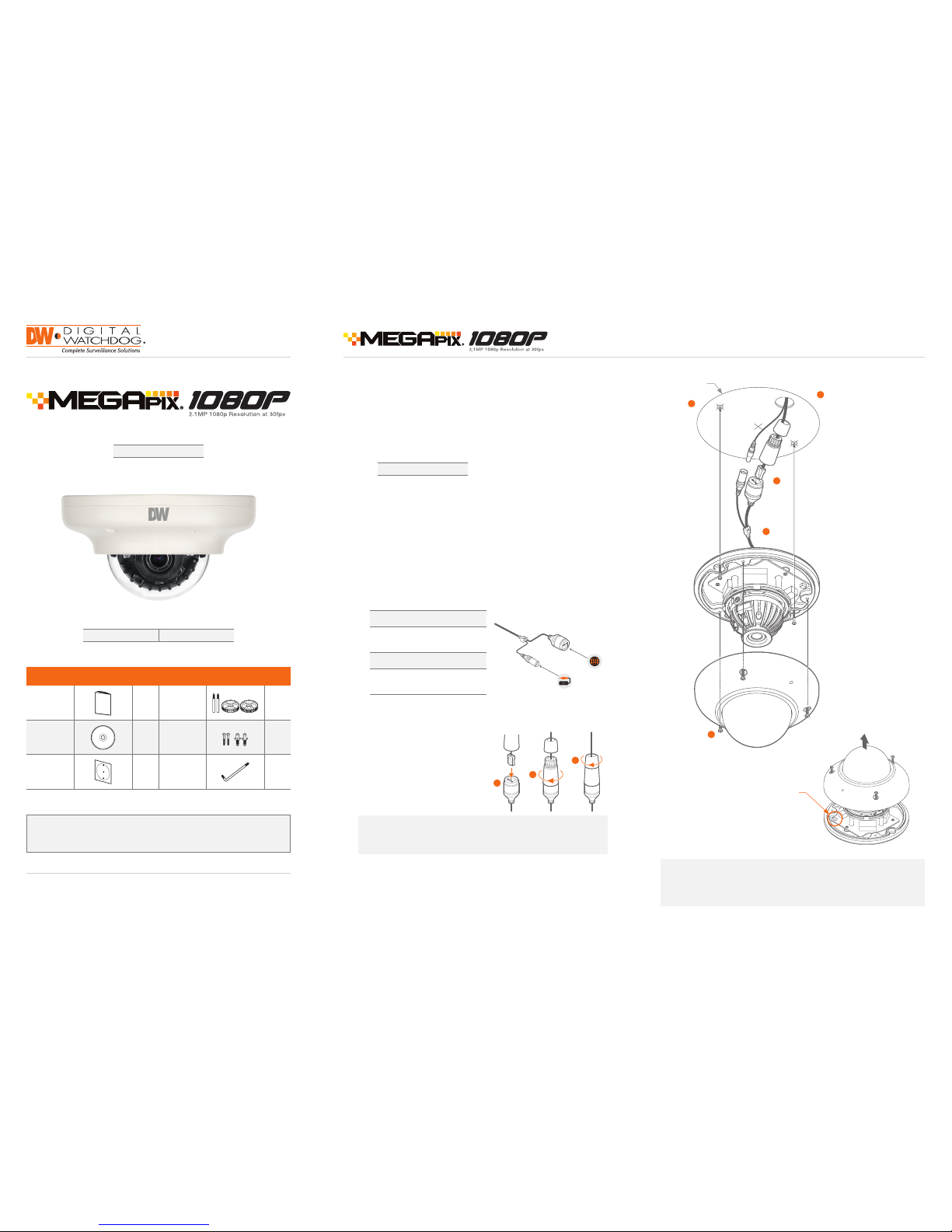
Step 1 – PREPARING TO MOUNT THE CAMERA
Step 3 – INSTALLING THE CAMERA
Step 2 – CABLING THE CAMERA TO EXTERNAL DEVICES
1. The mounting su rface must bear ve times the wei ght of your camera.
2. Do not let the cables g et caught in improper places or the el ectric line cover to
be damaged. This m ay cause a breakdown or re.
3. For the installation process, remove the dome cover from the camera module
by loosening the t hree (3) screws on the dome. Use the wrench provi ded with
the camera.
4. Using the mou nting template sheet or the camera itse lf, mark and dril l the
necessary holes in the wall or ceiling.
6. To use the camera’s water proof wiri ng:
(1)
. Install the LAN cabl e into (a).
(2)
. (b) will be assemble d to (a)
with a 1/4 turn.
(3)
. Thread (c) tightly to (b).
7. Use the ca mera’s 3-Axis gimbal to adjust the came ra’s tilt and angle. The
camera’s maximu m tilting angle is 70.
8. Assemble the do me cover over the camera body and det ach the protecting lm
from the dome bubble.
5. Pass the wires th rough the mount bracket and make all n ecessary connection s.
a. NE TWORK CONNECTIONS – If you a re using a PoE Switch, connect the
camera using a n Ethernet cabl e for both data and power.
b. NET WORK CONNECTIONS – If you are using a n on-PoE switch, connect
the camera to the sw itch using an Ethernet cable for data tra nsmission and
use a power adapter to power t he camera.
Power Requirements
DC 12 V
PoE IEEE 802.3at PoE+ / PoE Class 2
Power Consumption
LED Off: 1.92W, 160mA
LED On: 2.7W, 230mA (IR mo dels only)
NETWORK
CONNECTION
POWER
1
2
3
5
4
Template
Sheet
Reset
Button
Quick Start Guide
Quick Start Guide
Username: admin Password: admin
Attentio n: This document is in tended to serve as a qu ick reference page f or initial set-up.
It is recommen ded that the user rea d the entire instru ction manual for co mplete and proper
camera usage.
Tel: 866-4 46-3595 / 813- 888-9555
Technical Support Hours:
9:00AM – 8:0 0PM EST, Monday thru Friday
digital-watchdog.co m
WHAT’S IN THE BOX
QSG Manua l 1 Set
Mount Bolt &
Nut – 2pcs
1 Set
Manual CD 1 Set
Screw & Plas tic
Anchor – 2pc s
1 Set
Template Sheet
for installing by
Bolt & Nut
1 Set Torx Wren ch 1 Set
Note: To ensure moisture sea l, make sure the o-ri ng is in place between
(a) and (b). In extreme environm ents use of an outdoor rated sealer
is recommended.
Resetting the camera: To reset the camera, use the tip of a pa per clip or
a pencil and pres s the reset button. Pressing the but ton for ve (5) seconds
will initiate a came ra-wide reset of all the settings, includ ing network set tings.
a
b
c
Page 2
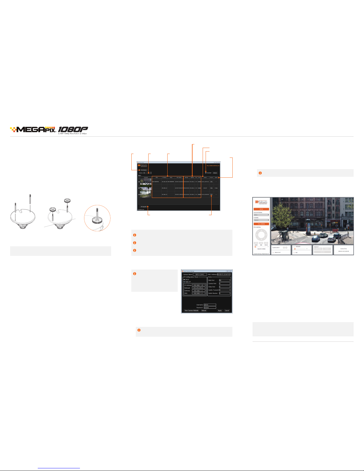
Step 5 – WEB VIEWER
Once the came ra’s network set tings have been setu p properly, you can access the
camera’s web viewer usin g the DW IP Finder™. To open the camera’s web viewer:
1. Find the camera using the DW IP Find er™.
2. Doubl e-click on the camera’s view in the results ta ble.
3. Press th e ‘View Camera Website’. The camera’s web viewer will ope n up in
your default web brows er.
4. Enter the c amera’s username and password (default a re admin / admin).
5. If you are a ccessing the camera for the rst ti me, install the VLC les i n
order to view video f rom the camera.
Step 3 – INSTALLING THE CAMERA (CONT.)
Installation using Mount Bolt and Screws:
1. Using the template she et, make and drill t he cabling holes on the wall/ceiling.
2. Secure the two l ong mounting screws to the camera’s base.
3. Pass the wires thro ugh the mount bracket and make all ne cessary connections.
4. Mount the ca mera to the mounting surface by usi ng the 2 mounting nuts.
Rotate the locking d iscs over the screws until the camera is h eld tightly from
the mounting surface.
Quick Start Guide
Note: The came ra’s maximum til ting angle is 70°
4. The camera’s default network information is:
Network Setup
1. Run the CD included with th e camera and click on the DW IP Finde r™ le.
2. Th e software will scan your net work for all supported came ras and display the
results in the tabl e. Allow up to 5 seconds for t he IP Finder to nd the camera on
the network.
3. Sel ect a camera from the list by double-cl icking on the camera’s image or
clicking on the ‘Cl ick’ button under the IP Co nf. column. The camera’s net work
information will appear. If necessary, you can adjust the camera’s network type.
Select DHC P if the internet servi ce is dynamic IP. This will allow the ca mera to
receive its IP a ddress from the DHCP se rver.
Select STATIC to manuall y enter the camera’s IP addre ss, subnet mask,
Gateway and DNS in formation.
Contact your network administrator for more information.
Default TCP/IP information
• IP: 192.168.1.80
• Subnet Mask: 255.255.255.0
• G atew ay: 192.1 68.1.1
• D NS: 1 68.12 6.6 3.1
6. To save the chan ges made to the camera’s settings, input t he ID and PW of the
camera for authentication and click ‘Save’.
7. If the camera ne eds to be rebooted after the settings we re changed, press the
‘Reboot’ but ton. The camera will cycle power and wil l appear back in the search
results once the re boot is complete.
5. To view the ca mera’s web viewer, click on ‘View C amera Website’.
‘Port Forwa rding’ has to be set in your net work’s router for externa l access
to the camera .
Default ID / PW : ad min / admin
Rev Date: 3/16
Copyright © D igital Watchd og. All right s reser ved. Speci fications
and pricing ar e subject to ch ange without n otice.
Note: Please see th e full product manual for web viewer s etup, functions
and camera set tings options.
Step 4 – DW IP FINDER
™
Use the DW IP Finder™ included in the c amera’s accessory CD to scan the net work
and detect all MEGA pix® cameras, set the ca mera’s network set tings, perform
rmware upgrad e or access the camera’s web client.
DWCMF10M28T
DWCMF21M4TIR
DWCMF10M28T
DWCMF21M4TIR
Firmware Upgrade Open Camer a's IP
Conguration Screen
Camera Uptime
Camera Name,
Model, IP Address,
and MAC Addre ss
Camera's Firmware
Search for
Cameras
View Camer a's
Thumbnail View
Camera's Network Settings
Filter Search
Results
 Loading...