


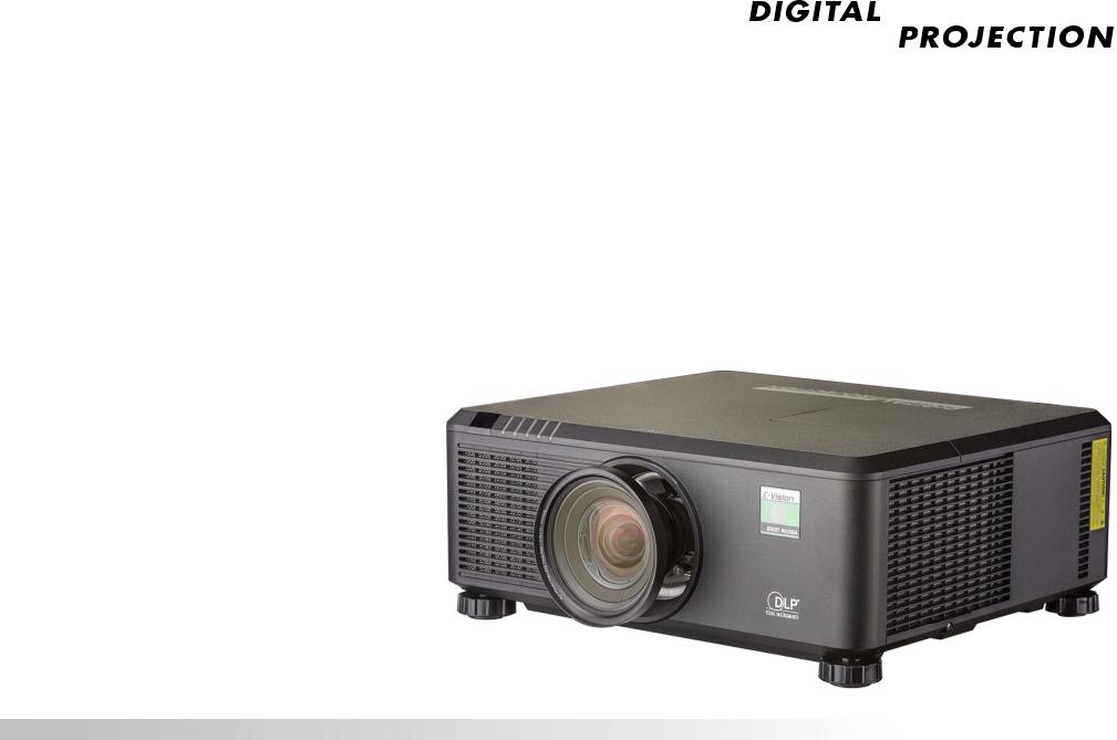
E-Vision 6900 Series
High Brightness Digital Video Projector
4INSTALLATION AND QUICK-START GUIDE
4CONNECTION GUIDE
4OPERATING GUIDE
4REFERENCE GUIDE
Rev A February 2017
118-049A
Digital Projection E-Vision 6900 Series
About This Document |
Notes |
Please follow the instructions in this manual carefully to ensure safe and long-lasting use of the projector.
Keep this manual handy for future reference.
Symbols used in this manual
Many pages in this document have a dedicated area for notes. The information in that area is accompanied by the following symbols:
ELECTRICAL WARNING: this symbol indicates that there is a danger of electrical shock unless the instructions are closely followed.
WARNING: this symbol indicates that there is a danger of physical injury to yourself and/or damage to the equipment unless the instructions are closely followed.
 NOTE: this symbol indicates that there is some important information that you should read.
Product revision
Because we at Digital Projection continually strive to improve our products, we may change specifications and designs, and add new features without prior notice.
Legal notice
Trademarks and trade names mentioned in this document remain the property of their respective owners.
Digital Projection disclaims any proprietary interest in trademarks and trade names other than its own.
Copyright © 2017 Digital Projection Ltd. All rights reserved.
Rev A February 2017
page i

Digital Projection E-Vision 6900 Series
Introduction |
Notes |
Congratulations on your purchase of this Digital Projection product.
Your projector has the following key features:
•Support for Side by Side, Frame Packing, Frame Sequential and Top Bottom 3D formats.
•HDBaseT® for reception of uncompressed High Definition Video up to 100 m from the source.
•Swappable color wheels for high brightness and color critical applications.
•DynamicBlack™ for improved black levels in dark scenes.
•Independent control of hue, saturation and gain for primary and secondary colors.
•Vertical and horizontal keystone correction.
•Control via LAN and RS232.
•Motorized lens mount.
A serial number is located on the product label. Please record it here:
Rev A February 2017
page ii

Digital Projection E-Vision 6900 Series
CONTENTS |
|
INSTALLATION AND QUICK-START GUIDE............................... |
1 |
PROJECTOR OVERVIEW................................................................ |
3 |
Front and rear views.............................................................................. |
3 |
CONNECTING THE POWER SUPPLY.............................................. |
4 |
Voltage selection.................................................................................... |
4 |
REMOTE CONTROL....................................................................... |
5 |
Infrared reception................................................................................... |
8 |
CONTROL PANEL........................................................................... |
9 |
Indicators............................................................................................. |
10 |
CHANGING THE LENS, LAMPS, FILTER AND COLOR WHEEL..... |
11 |
Inserting a new lens............................................................................. |
11 |
Removing the lens............................................................................... |
11 |
Changing the lamps............................................................................. |
12 |
Changing the filter................................................................................ |
13 |
Changing the color wheel.................................................................... |
14 |
POSITIONING THE SCREEN AND PROJECTOR........................... |
15 |
OPERATING THE PROJECTOR.................................................... |
16 |
Switching the projector on................................................................... |
16 |
Selecting an input signal or test pattern............................................... |
16 |
Input signal......................................................................................... |
16 |
Test pattern......................................................................................... |
16 |
Adjusting the lens................................................................................ |
17 |
Zoom................................................................................................ |
17 |
Focus................................................................................................ |
17 |
Shift.................................................................................................. |
17 |
Adjusting the image............................................................................. |
17 |
Orientation.......................................................................................... |
17 |
Aspect ratio........................................................................................ |
17 |
Picture............................................................................................... |
17 |
Switching the projector off................................................................... |
18 |
CONNECTION GUIDE............................................................................. |
19 |
SIGNAL INPUTS AND OUTPUTS .................................................. |
21 |
CONTROL CONNECTIONS........................................................... |
22 |
Rev A February 2017
page iii

Digital Projection E-Vision 6900 Series
CONTENTS (continued) |
|
OPERATING GUIDE................................................................................. |
23 |
USING THE PROJECTOR............................................................. |
25 |
Main menu........................................................................................... |
25 |
Lens menu........................................................................................... |
26 |
Lens Memory...................................................................................... |
27 |
Image menu......................................................................................... |
28 |
Image Mode........................................................................................ |
28 |
Brightness and Contrast......................................................................... |
28 |
Gamma............................................................................................. |
29 |
Dynamic Black..................................................................................... |
29 |
Saturation, Hue, Sharpness and Noise Reduction......................................... |
29 |
Position and Phase............................................................................... |
30 |
Resync.............................................................................................. |
30 |
Color menu.......................................................................................... |
31 |
Color Space........................................................................................ |
31 |
Color Temperature................................................................................ |
32 |
Trim.................................................................................................. |
33 |
Hue / Saturation / Gain.......................................................................... |
33 |
Geometry menu................................................................................... |
35 |
Aspect Ratio....................................................................................... |
35 |
Keystone............................................................................................ |
36 |
Corner Adjustment................................................................................ |
38 |
Overscan........................................................................................... |
39 |
3D menu.............................................................................................. |
40 |
The 3D Swap setting explained................................................................ |
40 |
3D types............................................................................................ |
41 |
Frame rate multiplication in 3D images....................................................... |
42 |
Lamps menu........................................................................................ |
43 |
Setup menu......................................................................................... |
44 |
Network............................................................................................. |
45 |
RS232............................................................................................... |
45 |
Security............................................................................................. |
46 |
Filter................................................................................................. |
46 |
EDID Mode......................................................................................... |
47 |
Projector ID Control.............................................................................. |
47 |
System.............................................................................................. |
48 |
Information menu................................................................................. |
49 |
Source information............................................................................... |
49 |
Factory Reset...................................................................................... |
49 |
MENU MAP................................................................................... |
50 |
Rev A February 2017
page iv

Digital Projection E-Vision 6900 Series |
|
CONTENTS (continued) |
|
REFERENCE GUIDE................................................................................ |
55 |
THE DMD™.................................................................................. |
57 |
SCREEN REQUIREMENTS............................................................ |
59 |
Fitting the image to the DMD™........................................................... |
59 |
WUXGA images displayed full width.......................................................... |
59 |
WUXGA images displayed with a height of 1080 pixels.................................. |
60 |
WUXGA images displayed full height......................................................... |
61 |
Diagonal screen sizes.......................................................................... |
62 |
Fitting the image to the screen............................................................ |
63 |
Positioning the screen and projector................................................... |
64 |
POSITIONING THE IMAGE............................................................ |
65 |
FRAME RATES AND PULLDOWNS EXPLAINED........................... |
67 |
Interlaced and progressive scan.......................................................... |
67 |
Frame rates of image sources............................................................. |
67 |
Pulldowns - conversion into destination formats.................................. |
68 |
2:3 (normal) pulldown............................................................................ |
68 |
2:3:3:2 (advanced) pulldown................................................................... |
69 |
APPENDIX A: LENS PART NUMBERS.......................................... |
70 |
APPENDIX B: SUPPORTED SIGNAL INPUT MODES..................... |
71 |
2D formats........................................................................................... |
71 |
3D formats........................................................................................... |
73 |
APPENDIX C: WIRING DETAILS................................................... |
74 |
RS232.................................................................................................. |
74 |
Trigger 1 & Trigger 2............................................................................ |
75 |
Wired remote control........................................................................... |
75 |
3D Sync IN / OUT................................................................................ |
75 |
APPENDIX D: GLOSSARY OF TERMS.......................................... |
76 |
Rev A February 2017
page v
E-Vision 6900 Series
High Brightness Digital Video Projector
4 INSTALLATION AND QUICK-START GUIDE
Rev A February 2017

Digital Projection E-Vision 6900 Series |
IN THIS GUIDE |
|
|
IN THIS GUIDE |
|
Projector Overview............................................................................................. |
3 |
Front and rear views.................................................................................................... |
3 |
Connecting The Power Supply........................................................................ |
4 |
Voltage selection......................................................................................................... |
4 |
Remote Control.................................................................................................... |
5 |
Infrared reception........................................................................................................ |
8 |
Control Panel......................................................................................................... |
9 |
Indicators.................................................................................................................... |
10 |
Changing The Lens, Lamps, Filter And Color Wheel.............................. |
11 |
Inserting a new lens.................................................................................................. |
11 |
Removing the lens..................................................................................................... |
11 |
Changing the lamps.................................................................................................. |
12 |
Changing the filter..................................................................................................... |
13 |
Changing the color wheel......................................................................................... |
14 |
Positioning The Screen And Projector....................................................... |
15 |
Operating The Projector.................................................................................. |
16 |
Switching the projector on....................................................................................... |
16 |
Selecting an input signal or test pattern................................................................. |
16 |
Input signal...................................................................................................................... |
16 |
Test pattern...................................................................................................................... |
16 |
Adjusting the lens...................................................................................................... |
17 |
Zoom............................................................................................................................... |
17 |
Focus............................................................................................................................... |
17 |
Shift................................................................................................................................. |
17 |
Adjusting the image.................................................................................................. |
17 |
Orientation....................................................................................................................... |
17 |
Aspect ratio...................................................................................................................... |
17 |
Picture............................................................................................................................. |
17 |
Installation and Quick-Start Guide
Switching the projector off....................................................................................... |
18 |
Rev A February 2017
Digital Projection E-Vision 6900 Series |
PROJECTOR OVERVIEW |
|
|
Projector Overview |
1 |
2 |
3 |
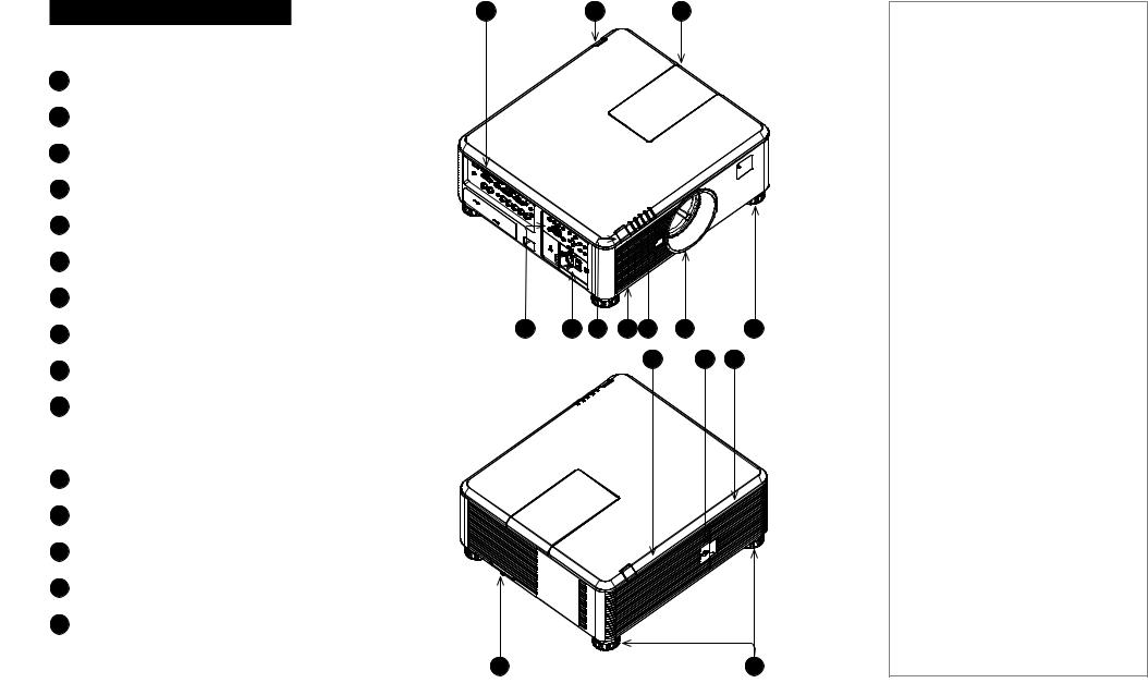
and rear views
Connection panel
Rear infrared window
Color wheel door
Control panel
Power switch and power connection Front infrared window
Air inlet
Indicators
Lens mount
10 Adjustable foot
Lamp compartment with air outlets
Lamp compartment door
Air outlet
Air inlet and filter
15 Adjustable feet
4 |
5 |
6 |
7 |
8 |
9 |
|
10 |
|
|
|
|
11 |
|
12 |
13 |
Notes
14 |
15 |
Installation and Quick-Start Guide |
Rev A February 2017 |
|
page 3 |

Digital Projection E-Vision 6900 Series |
CONNECTING THE POWER SUPPLY |
|
|
Connecting The Power Supply
Adjust the VOLTAGE SELECT |
1 to |
|
the required voltage, then |
|
push the mains |
connector into the |
2 . |
|
1 |
2 |
Voltage selection
The VOLTAGE SELECT switch must be set to match the power supply you are using:
Voltage of power supply used |
Position of VOLTAGE SELECT switch |
AC 100 - 130 V outlet
Notes
 Use only the power cable provided.
 Ensure that the power outlet includes a ground connection as this equipment MUST be earthed.
 Handle the power cable carefully and avoid sharp bends. Do not use a damaged power cable.
AC 200-240 V (single phase) outlet
|
|
|
|
|
|
|
|
|
|
|
|
|
|
|
|
|
|
|
|
|
|
|
|
|
Installation and Quick-Start Guide |
|
|
Rev A February 2017 |
|
|
|
|
|
page 4 |
Digital Projection E-Vision 6900 Series |
REMOTE CONTROL |
|
|
Control
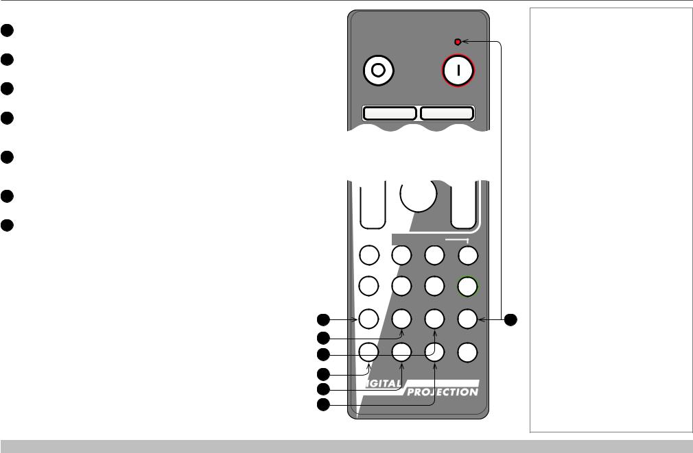
Power ON / OFF
Turns power on and off.
2Pic Mute ON / OFF
Shows and hides the projected image.
When OFF, the light source is completely switched off and the screen is black.
2OSD ON / OFF
Enable and disable screen timeout messages and control whether to show the OSD during projection.
MENU
Access the OSD. If the OSD is open, press this button to go back to the previous menu.
5Navigation (arrows and OK)
Navigate through the menus with the arrows, confirm your choice with OK.
In lens adjustment modes, the arrows are used to move, zoom or focus the lens. See 11 below.
In lens adjustment modes, or when the OSD is not showing, the OK button switches between modes: Shift Adjustment and Zoom / Focus Adjustment.
EXIT
Go up one level in the OSD. When the top level is reached, press to close the OSD.
FREEZE
Freeze the current frame.
DEFAULT
When editing a parameter, press this button to restore the default value.
INFO
Access information about the projector.
10RE-SYNC
Re-synchronise with the current input signal.
continues on next page...
1
2
3
4
5
6
7
Notes
OFF |
|
|
ON |
|
Pic Mute |
|
|
OFF |
ON |
|
|
|
OSD |
|
|
OFF |
ON |
|
|
MENU |
|
DEFAULT |
|
|
|
|
8 |
|
OK |
|
|
|
|
|
9 |
EXIT |
|
|
INFO |
FREEZE |
|
RE-SYNC |
|
|
|
|
10 |
FOCUS |
LENS |
ZOOM |
|
IN |
|
|
IN |
|
SHIFT |
|
|
OUT |
|
|
OUT |
|
USER PRESET |
|
|
A |
B |
C |
D |
HDMI1 |
HDMI2 |
DVI |
ALT |
1 |
2 |
3 |
|
BRI |
CON |
GAMMA |
ADDR |
DISPLAYPORT |
HD-T |
3GSDI |
|
4 |
5 |
6 |
|
R |
G |
B |
ALL |
VGA |
COMP1 |
COMP2 |
TEST |
7 |
8 |
9 |
0 |
3D |
EYE |
PIP |
SWAP |
Installation and Quick-Start Guide |
Rev A February 2017 |
|
page 5 |

Digital Projection E-Vision 6900 Series |
REMOTE CONTROL |
11LENS adjustment
FOCUS IN / OUT: adjust focus.
SHIFT: press and hold this button, then use the Navigation arrow buttons to move the lens.
ZOOM IN / OUT: adjust zoom.
12 |
USER PRESET A, B, C, D |
11 |
|
||
|
This featrure is not supported. |
|
13 |
ALT |
|
|
Press and hold this button to access alternative functions for all |
|
|
buttons with a green label. |
|
14 |
DVI / GAMMA / numeric input 3 |
|
|
Select the DVI input. |
12 |
|
Use with ALT to switch to the next Gamma value: |
|
|
...1.0, 1.8, 2.0, 2.2, 2.35, 2.5... |
|
15HDMI 2 / CON / numeric input 2
Select the HDMI 1 input.
Use with ALT to bring up the Contrast control, then adjust the value with the LEFT and RIGHT arrow buttons.
16HDMI 1 / BRI / numeric input 1
Select the HDMI 1 input.
Use with ALT to bring up the Brightness control, then adjust the value with the LEFT and RIGHT arrow buttons.
17TEST / SWAP / numeric input 0
Show a test pattern. Press again to show the next test pattern:
...Off, White, Black, Red, Green, Blue, CheckerBoard,
CrossHatch, V Burst, H Burst, ColorBar...
The SWAP function is not supported.
continues on next page...
FREEZE |
RE-SYNC |
Notes |
FOCUS |
LENS |
ZOOM |
|
|
IN |
|
|
IN |
|
|
SHIFT |
|
|
|
OUT |
|
|
OUT |
|
|
USER PRESET |
|
|
|
A |
B |
C |
D |
|
HDMI1 |
HDMI2 |
DVI |
ALT |
|
1 |
2 |
3 |
|
13 |
|
|
|
|
|
BRI |
CON |
GAMMA |
ADDR |
14 |
DISPLAYPORT |
HD-T |
3GSDI |
||
4 |
5 |
6 |
|
15 |
|
|
|
|
|
R |
G |
B |
ALL |
16 |
VGA |
COMP1 |
COMP2 |
TEST |
|
7 |
8 |
9 |
0 |
17 |
|
|
|
|
|
3D |
EYE |
PIP |
SWAP |
|
Remote control
Installation and Quick-Start Guide |
Rev A February 2017 |
|
page 6 |
Digital Projection E-Vision 6900 Series |
REMOTE CONTROL |
17DISPLAYPORT / R / numeric input 4
DisplayPort is not supported.
18HD-T / G / numeric input 5
Select the HDBaseT input.
193GSDI / B / numeric input 6
3G-SDI is not supported.
20VGA / 3D / numeric input 7
Select the VGA input.
Use with ALT to toggle the 3D Format setting between Off and Auto.
21COMP1 / EYE / numeric input 8
Select the Component 1 input.
Use with ALT to switch between left and right eye 3D dominance.
22COMP2 / PIP / numeric input 9
Component 2 and PIP are not supported.
23ADDR / ALL (with red indicator at the top)
Assign and unassign an IR remote address.
To assign an address:
1.Press and hold this button until the indicator starts flashing.
2.Release this button and while the indicator is still flashing, enter a two-digit address using the numeric input buttons. The indicator will flash three times quickly to confirm the change.
To unassign an address and return to the default address 00,
•Press and hold ALT and this button simultaneously until the indicator flashes to confirm the change.
17
18
19
20
21
22
OFF |
ON |
Pic Mute
OFF ON
Remote control top
OUT |
|
|
OUT |
|
USER PRESET |
|
|
A |
B |
C |
D |
HDMI1 |
HDMI2 |
DVI |
ALT |
1 |
2 |
3 |
|
BRI |
CON |
GAMMA |
ADDR |
DISPLAYPORT |
HD-T |
3GSDI |
|
4 |
5 |
6 |
|
R |
G |
B |
ALL |
VGA |
COMP1 |
COMP2 |
TEST |
7 |
8 |
9 |
0 |
3D |
EYE |
PIP |
SWAP |
Remote control bottom
Notes
23
Installation and Quick-Start Guide |
Rev A February 2017 |
|
page 7 |
Digital Projection E-Vision 6900 Series REMOTE CONTROL
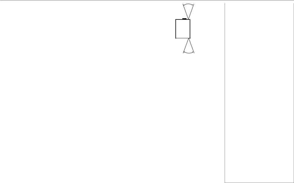
Infrared reception |
|
|
40° |
Notes |
|
The projector has infrared sensors at the front and back. |
|
|
The angle of acceptance is 40°. Make sure that the remote control is within the angle of acceptance when trying to control the projector.
40°
Infrared reception
Installation and Quick-Start Guide |
Rev A February 2017 |
|
page 8 |

Digital Projection E-Vision 6900 Series CONTROL PANEL
|
|
|
|
|
|
|
|
|
|
|
|
|
|
|
|
Panel |
|
|
|
|
|
|
|
|
|
|
|
|
|
Notes |
|
POWER |
1 |
2 |
3 |
4 |
5 |
6 |
|
||||||||
|
|
|
|
|
|
|
|
|
|
|
|
|
|||
Switches the projector on and off |
|
|
|
|
|
|
|
|
|
|
|
|
|
||
(STANDBY). |
|
|
|
|
|
|
|
|
|
|
|
|
|
||
INPUT |
|
|
|
|
|
|
|
|
|
|
|
|
|
||
|
|
|
|
|
|
|
|
|
|
|
|
|
|||
Switches to the next input source. |
POWER |
INPUT |
AUTO |
ASPECT |
CENTER |
SHUTTER |
|||||||||
AUTO SYNC |
SYNC |
LENS |
|||||||||||||
|
|
|
|
|
|
|
|
|
|||||||
|
|
|
|
|
|
|
|
|
|
|
|
|
|||
Re-synchronises with the current input |
|
|
|
|
|
|
|
|
|
|
|
|
|
||
signal. |
|
|
|
|
|
|
|
|
|
|
|
|
|
||
ASPECT
Changes the aspect ratio.
CENTER LENS
Centers the lens.
6 SHUTTER
Shows and hides the projected image. When OFF, the light source is completely switched off and the screen is black.
MENU
Displays and exits the OSD.
8Arrow buttons & ENTER
Navigation buttons used to highlight menu entries in the OSD.
Press ENTER to open or execute the |
7 |
8 |
9 |
10 |
11 |
12 |
highlighted menu entry. |
|
|
|
|
|
|
EXIT
Exits the current OSD page and enters the level above.
LENS SHIFT arrow buttons
Each of these buttons moves the lens in the specified direction.
FOCUS plus and minus buttons
Used to move the focus in and out.
12ZOOM plus and minus buttons
Used to zoom in and out.
Installation and Quick-Start Guide |
Rev A February 2017 |
|
page 9 |
Digital Projection E-Vision 6900 Series CONTROL PANEL
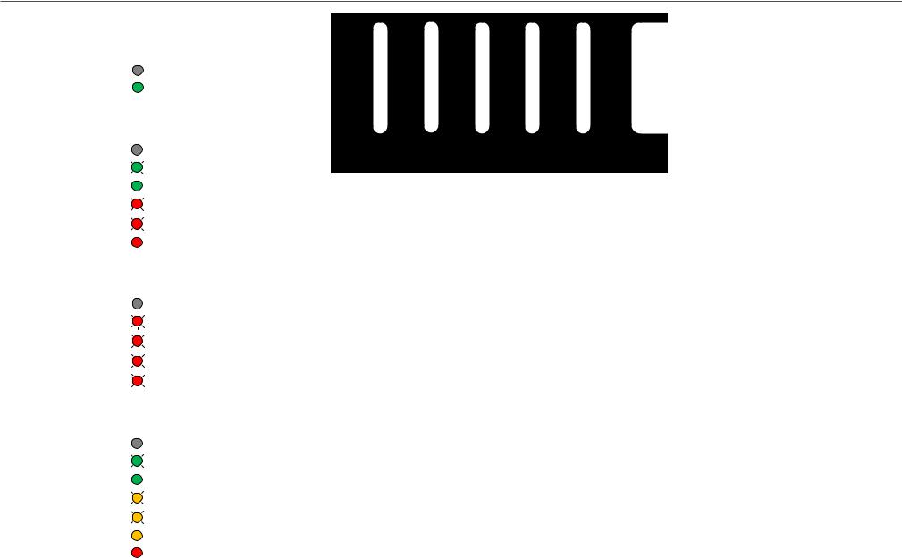
Indicators |
|
|
|
Notes |
|
|||
SHUTTER |
|
|
|
|
|
|||
Behavior |
|
Meaning |
|
|
|
|||
Off |
|
The shutter is open. |
|
|
|
|||
Steady green |
|
The shutter is closed. |
|
|
|
|||
LAMP 2 / LAMP 1 |
|
|
|
|
|
|||
Behavior |
|
Meaning |
|
|
|
|||
Off |
|
The lamp is switched off. |
SHUTTER LAMP 2 LAMP 1 STATUS POWER |
|
||||
Flashing green |
|
The lamp is preparing to switch on. |
|
|
|
|||
Steady green |
|
The lamp is switched on. |
|
|
|
|||
One red flash, pause |
|
No lamp. |
|
|
|
|||
Six red flashes, pause |
|
The lamp failed to switch on. |
|
|
|
|||
Steady red |
|
The lamp is end-of-life. |
|
|
|
|||
STATUS |
|
|
|
|
|
|||
Behavior |
|
Meaning |
|
|
|
|||
Off |
|
No error. |
|
|
|
|||
One red flash, pause |
|
Cover error. |
|
|
|
|||
Two red flashes, pause |
|
|
Temperature error. |
|
|
|
||
|
|
|
|
|
||||
|
|
|
|
|
||||
|
|
|
|
|
|
|
|
|
Three red flashes, pause |
|
|
System error. |
|
|
|
||
|
|
|
|
|
||||
|
|
|
|
|
|
|
|
|
Four red flashes, pause |
|
|
Fan error. |
|
|
|
||
|
|
|
|
|
||||
POWER |
|
|
|
|
|
|||
Behavior |
|
Meaning |
|
|
|
|||
Off |
|
The projector is switched off. |
|
|
|
|||
Flashing green |
|
|
|
The projector is warming up. |
|
|
|
|
|
|
|
|
|
|
|||
|
|
|
|
|
|
|||
Steady green |
|
The projector is switched on. |
|
|
|
|||
Flashing amber |
|
|
The projector is cooling down. |
|
|
|
||
|
|
|
|
|
||||
|
|
|
|
|
||||
|
|
|
|
|
|
|||
One amber flash, pause |
|
|
Keypad Lock warning. |
|
|
|
||
|
|
|
|
|
||||
Steady amber |
|
The projector is in Network STANDBY mode (<3W). |
|
|
||||
Steady red |
|
The projector is in Eco STANDBY mode (<0.5W). |
|
|
||||
|
|
|
|
|
|
|
|
|
Installation and Quick-Start Guide |
Rev A February 2017 |
|
page 10 |

Digital Projection E-Vision 6900 Series |
CHANGING THE LENS, LAMPS, FILTER AND COLOR WHEEL |
|
|
Changing The Lens, Lamps, Filter And Color Wheel
Inserting a new lens
1. Remove the front and rear lens caps.
2.Position the lens so that the labels are at the top, and gently insert it all the way into the lens mount.
3.Push the lens in firmly and turn it clockwise until it clicks into place.
Removing the lens
1. Push in the lens release lever, and turn the lens anti-clockwise. 2. Remove the lens..
Notes
 Always allow the lamp to cool for 5 minutes before:
-disconnecting the power
-moving the projector
 Before changing the lens, always make sure the projector is switched off and fully disconnected from its power supply.
 When changing the lens, avoid using excessive force as this may damage the equipment.
 The lens is shipped separately.
 Take care to preserve the original lens packaging and protective caps for future use.
Installation and Quick-Start Guide |
Rev A February 2017 |
|
page 11 |

Digital Projection E-Vision 6900 Series |
CHANGING THE LENS, LAMPS, FILTER AND COLOR WHEEL |
Changing the lamps
1.Unscrew the captive screw holding the lamp compartment door.
2.Remove the door to reveal the lamp modules.
3.Unscrew the three captive screws holding each lamp module in its place.
4.Pull out the old lamp modules and insert the new ones.
5.Use the three captive screws on each module to hold it into position, then replace the lamp compartment cover and secure it with the screw.
Notes


 Always allow the lamp to cool for
5 minutes before:
- disconnecting the power - moving the projector
 The lamp must be changed only by suitably qualified personnel.
 The projector will shut down if the cover is opened whilst in operation.
 The filters should be changed at the same time as the lamp is changed.
Installation and Quick-Start Guide |
Rev A February 2017 |
|
page 12 |
Digital Projection E-Vision 6900 Series |
CHANGING THE LENS, LAMPS, FILTER AND COLOR WHEEL |
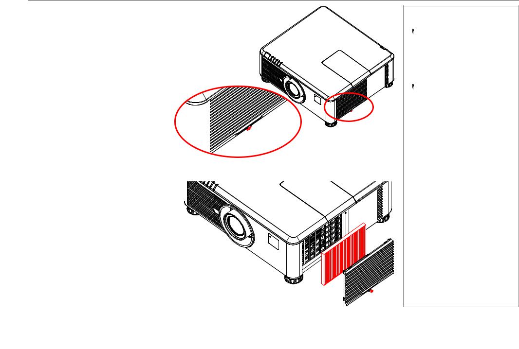
Changing the filter
1.Loosen the captive screw at the bottom of the filter door.
Notes
 Always allow the lamp to cool for 5 minutes before:
-disconnecting the power
-moving the projector
 The lamp must be changed only by suitably qualified personnel.
 The projector will shut down if the cover is opened whilst in operation.
 The filters should be changed at the same time as the lamp is changed.
2.Remove the door and the filter as shown in the illustration.
3.Replace the filter, then close the door and tighten the screw to secure it in place.
Installation and Quick-Start Guide |
Rev A February 2017 |
|
page 13 |

Digital Projection E-Vision 6900 Series |
CHANGING THE LENS, LAMPS, FILTER AND COLOR WHEEL |
Changing the color wheel
1.Slide open the lamp compartment cover as shown in the picture.
2.Unscrew the two captive screws securing the color wheel.
Notes
 Always allow the lamp to cool for 5 minutes before:
-disconnecting the power
-moving the projector
 The color wheel must be changed only by suitably qualified personnel.
 The projector will shut down if the cover is opened whilst in operation.
3.Lift and pull the color wheel handle to remove the color wheel.
4.Insert a new color wheel, lower the handle, fasten the screws and replace the lamp compartment cover.
Installation and Quick-Start Guide |
Rev A February 2017 |
|
page 14 |
Digital Projection E-Vision 6900 Series |
POSITIONING THE SCREEN AND PROJECTOR |
|
|
Positioning The Screen And Projector
1.Install the screen, ensuring that it is in the best position for viewing by your audience.
2.Mount the projector, ensuring that it is at a suitable distance from the screen for the image to fill the screen. Set the adjustable feet so that the projector is level, and perpendicular to the screen.
Alternatively, six M4 bolts (max length 16 mm [0.6 in]) can be used to attach the projector to a ceiling mount (optional accessory,).
Notes
Always allow the lamp to cool for 5 minutes before:
-disconnecting the power
-moving the projector
Ensure that there is at least 50cm (20in) of space between the ventilation outlets and any wall, and 10cm (4in) on all other sides.
If ceiling mounting, ensure there is 30cm (12in) of space between the projector and ceiling.
Do not stack the projectors.
Do not tilt the projector more than ±10° from side to side when in use, as this may cause serious lamp failure, damage the lamp module and cause extra cost on replacement.
±360°
±10°
Location of the ceiling mount holes at the bottom of the projector
Installation and Quick-Start Guide |
Rev A February 2017 |
|
page 15 |

Digital Projection E-Vision 6900 Series |
OPERATING THE PROJECTOR |
|
|
Operating The Projector
Switching the projector on
•Connect the power cable between the mains supply and the projector. Switch on at the switch next to the power connector.
•Wait until the self-test has completed and the Power indicator on the projector control panel shows amber. The lamp will be off and the projector will be in STANDBY mode.
•Press on the control panel or POWER ON on the remote control.
The Power indicator on the control panel will flash green for a few seconds whilst the lamp comes up to full brightness. When the projector is ready for use, the Power indicator will show steady green.
Selecting an input signal or test pattern
Input signal
•Connect an image source to the projector. The signal should be automatically detected by the projector, and should be displayed within a two or three seconds.
•If more than one signal is connected, then select the image you want to display:
• On the control panel, press INPUT to cycle through the inputs,
or
•on the remote control, press the button for the input of your choice,
or
•on any device, press MENU to show the OSD (On-screen DIsplay), then highlight Input, then press OK/ENTER to open the list of inputs.
Test pattern
To display a test pattern:
1.Press MENU to open the OSD. Use the UP and DOWN arrow buttons to highliught Test Pattern, then press OK/ENTER to open the list of test patterns. Alternatively, on the remote control press TEST to open the same list.
2.Use the UP and DOWN arrow buttons to highlight the test pattern you wish to display and press OK/ENTER.
Notes
Before switching on the projector for the first time, make sure
the electric circuit is grounded. Poor grounding may damage the projector.
Always allow the lamp to cool for 5 minutes before:
-disconnecting the power
-moving the projector
 For full details of how to connect an image source to the projector, see the Connection Guide.
 For full details of how to use the controls and the menu system, see the Operating Guide.
Installation and Quick-Start Guide |
Rev A February 2017 |
|
page 16 |

Digital Projection E-Vision 6900 Series |
OPERATING THE PROJECTOR |
Adjusting the lens
Zoom
•Use the ZOOM +/− buttons on the control panel or the ZOOM IN/OUT buttons on the remote control to adjust the lens so that the image fills the screen.
Focus
•Use the FOCUS +/− buttons on the control panel or the FOCUS IN/OUT buttons on the remote control to adjust the lens until the image is sharp.
Shift
•Use the LENS SHIFT arrow buttons on the control panel to adjust the position of the image,
or press the SHIFT button on the remote control then use the arrow buttons to adjust the position of the image.
Adjusting the image
Orientation
•Use the Orientation settings in the Setup menu.
Aspect ratio
•Press the ASPECT button on the control panel to cycle through all the available settings. or
•use the Aspect Ratio setting in the Geometry menu.
Picture
•Open the Image menu, then use the sliders to adjust brightness, contract etc.
Notes
 For full details of how to use the controls and the menu system, see the Operating Guide.
Installation and Quick-Start Guide |
Rev A February 2017 |
|
page 17 |

Digital Projection E-Vision 6900 Series OPERATING THE PROJECTOR
Switching the projector off |
|
||
Notes |
|||
• Press |
on the control panel or POWER OFF on the remote control, then press the button a second time within 5 seconds to confirm. |
|
|
The lamp will go off, and the Power indicator on the control panel will flash amber for a few seconds whilst the lamp cools. The Power |
Always allow the lamp to cool for |
||
indicator on the control panel will then show amber and the projector will be in Standby mode. |
|||
• Switch the projector off completely from the switch next to the power connector. Disconnect the power cable from the projector. |
5 minutes before: |
||
- disconnecting the power |
|||
|
|
||
|
|
- moving the projector |
|
|
|
|
|
Installation and Quick-Start Guide |
Rev A February 2017 |
|
page 18 |

E-Vision 6900 Series
High Brightness Digital Video Projector
4 CONNECTION GUIDE
Rev A February 2017

Digital Projection E-Vision 6900 Series |
IN THIS GUIDE |
IN THIS GUIDE |
|
Signal Inputs And Outputs.............................................................................. |
21 |
Control Connections......................................................................................... |
22 |
Connection Guide |
Rev A February 2017 |
Digital Projection E-Vision 6900 Series |
SIGNAL INPUTS AND OUTPUTS |
|
|
3
4
6
7
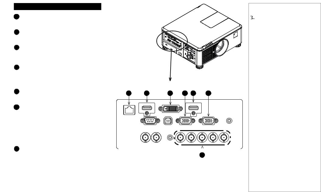
Inputs And Outputs
HDBaseT/LAN
Receives digital signal from HDBaseT-compliant devices.
HDMI II
This HDMI 1.4 input supports HDCP 1.1 and DVI
1.0.
DVI-D
This input can receive digital (DVI-D) signal from a compatible source.
Supports HDCP.
Monitor Out
Connect an analog monitor cable (VGA) to the 15pin D-type connector.
The connected monitor will display signal received via the VGA input.
HDMI I |
1 |
2 |
3 |
4 |
5 |
6 |
|
This HDMI 1.4 input supports HDCP 1.1 and DVI |
|||||||
|
|
|
|
|
|
||
1.0. |
|
|
|
|
|
|
VGA
This input receives analog signals from a computer.
When using this input, it is best to use a fully wired VGA cable to connect the source to the projector. This will allow the source to determine the projector’s capabilities via DDC and show an optimized image. Such cables can be identified as they have a blue connector shell.
Component |
|
|
|
|
|
||
Connect a set of RGsB, RGBHV or YCbCr cables |
|
|
|
7 |
|||
to the BNC connectors. |
|||
|
|
||
Notes
 For a complete listing of pin configurations for all signal and control connectors, see Wiring Details later in this Guide.
Connection Guide |
Rev A February 2017 |
|
page 21 |
Digital Projection E-Vision 6900 Series |
CONTROL CONNECTIONS |
|
|
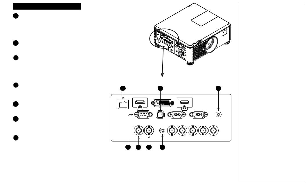
Connections
1HDBaseT/LAN
Receives digital signal from HDBaseT-compliant devices.
All of the projector’s features can be controlled via a LAN connection, using commands described in the Remote Communications Guide.
Service
The USB Service port is used for firmware updates only.
3Screen Trigger
The Trigger output can be connected to an electrically operated screen, automatically deploying the screen when the projector is switched on, and retracting the screen when the projector is switched to standby.
4RS-232
All of the projector’s features can be controlled via a serial connection, using commands described in the Remote Communications Guide.
3D Sync Out
Connect to a Z Screen or 3D IR emitter as appropriate.
63D Sync In
Connect the 3D sync from your graphics card or server.
7Wired Remote
The remote control can be connected using a standard 3.5 mm mini jack cable (tip-ring-sleeve, or TRS).
Notes
1 |
2 |
3 |
 Plugging in the remote control cable will disable infrared transmission.
4 |
5 |
6 |
7 |
Connection Guide |
Rev A February 2017 |
|
page 22 |
 Loading...