


|
USER MANUAL |
|
INSTALLATION AND QUICK-START GUIDE |
|
CONNECTION GUIDE |
|
OPERATING GUIDE |
E-Vision 6500 Series |
REMOTE COMMUNICATIONS GUIDE |
High Brightness Digital Video Projector |
|
|
|
LAMP2 |
TO |
AU |
LAMP1 |
|
|
|
RETURN |
|
ES |
|
|
|
|
|
ENTER |
WARNING  POWER
POWER
MENU
SHIFT |
LENS |
|
 ZOOM
ZOOM  +
+
 –
–
 FOCUS
FOCUS
Rev D July 2014 |
114-758D |

Digital Projection E-Vision 6500 Series |
|
|||
|
|
|
|
|
About This Document |
||||
|
|
Notes |
||
Please follow the instructions in this manual carefully to ensure safe and long-lasting use of the projector.
Keep this manual handy for future reference.
Symbols used in this manual
Many pages in this document have a dedicated area for notes. The information in that area is accompanied by the following symbols:
ELECTRICAL WARNING: this symbol indicates that there is a danger of electrical shock unless the instructions are closely followed.
WARNING: this symbol indicates that there is a danger of physical injury to yourself and/or damage to the equipment unless the instructions are closely followed.
 NOTE: this symbol indicates that there is some important information that you should read.
Product revision
Because we at Digital Projection continually strive to improve our products, we may change specifications and designs, and add new features without prior notice.
Legal notice
Trademarks and trade names mentioned in this document remain the property of their respective owners.
Digital Projection disclaims any proprietary interest in trademarks and trade names other than its own.
Copyright © 2014 Digital Projection Ltd. All rights reserved.
Rev D July 2014 |
i |

Digital Projection E-Vision 6500 Series |
|
|||
|
|
|
|
|
Introduction |
||||
|
|
Notes |
||
Congratulations on your purchase of this Digital Projection product.
Your projector has the following key features:
•Swappable color wheels for high brightness and color critical applications.
•BrilliantColor™ for increased system brightness.
•DynamicBlack™ for improved black levels in dark scenes.
•Frame sequential 3D support at up to 120Hz with support for DLP® Link™ glasses synchronisation only.
•Independent control of hue, saturation and gain for primary and secondary colors.
•Vertical keystone correction.
•Control via LAN and RS232.
•Motorized lens mount.
A serial number is located on the back of the projector. Please record it here:
Rev D July 2014 |
ii |

Digital Projection E-Vision 6500 Series |
|
CONTENTS |
|
INSTALLATION AND QUICK-START GUIDE............................... |
1 |
WHAT’S IN THE BOX?.................................................................... |
3 |
GETTING TO KNOW THE PROJECTOR.......................................... |
4 |
Front and rear views.............................................................................. |
4 |
Remote control...................................................................................... |
4 |
Control panel and indicators.................................................................. |
5 |
CHANGING THE LENS, LAMPS AND COLOR WHEEL..................... |
6 |
Removing the lens................................................................................. |
6 |
Fitting the lens....................................................................................... |
6 |
Changing the lamp................................................................................. |
7 |
Changing the color wheel...................................................................... |
8 |
POSITIONING THE SCREEN AND PROJECTOR ............................. |
9 |
OPERATING THE PROJECTOR.................................................... |
10 |
Switching the projector on................................................................... |
10 |
Selecting an input signal or test pattern............................................... |
10 |
Input signal......................................................................................... |
10 |
Test pattern......................................................................................... |
10 |
Adjusting the lens................................................................................ |
11 |
Zoom................................................................................................ |
11 |
Focus................................................................................................ |
11 |
Shift.................................................................................................. |
11 |
Adjusting the image............................................................................. |
11 |
Orientation.......................................................................................... |
11 |
Aspect ratio........................................................................................ |
11 |
Picture............................................................................................... |
11 |
Switching the projector off................................................................... |
12 |
CONNECTION GUIDE............................................................................. |
13 |
SIGNAL INPUTS AND OUTPUTS .................................................. |
15 |
Computer 1.......................................................................................... |
15 |
Computer 2.......................................................................................... |
15 |
Computer 3.......................................................................................... |
15 |
Component.......................................................................................... |
15 |
Video or S-Video.................................................................................. |
15 |
Monitor Out.......................................................................................... |
15 |
SUPPORTED SIGNAL INPUT MODES........................................... |
16 |
CONTROL CONNECTIONS........................................................... |
18 |
Screen Trigger..................................................................................... |
18 |
USB Service Port................................................................................. |
18 |
Wired Remote Control......................................................................... |
18 |
RS232.................................................................................................. |
18 |
LAN...................................................................................................... |
18 |
Rev D July 2014 |
iii |

Digital Projection E-Vision 6500 Series |
|
WIRING DETAILS......................................................................... |
19 |
Signal inputs and outputs.................................................................... |
19 |
Monitor video output (VGA)..................................................................... |
19 |
Computer 1 video input: analog computer (VGA).......................................... |
19 |
Computer 2 video input: RGBHV, RGsB or YCbCr........................................ |
19 |
Computer 3 video input: DVI-D................................................................ |
20 |
Component video input.......................................................................... |
21 |
Video input......................................................................................... |
22 |
S-Video input...................................................................................... |
22 |
Control connections............................................................................. |
23 |
Screen Trigger output............................................................................ |
23 |
RS232 Serial control input...................................................................... |
23 |
Wired remote control connection............................................................. |
23 |
LAN connection................................................................................... |
24 |
OPERATING GUIDE................................................................................. |
25 |
USING THE REMOTE CONTROL................................................... |
27 |
USING THE MENUS...................................................................... |
28 |
Navigating the menus.......................................................................... |
28 |
Submenus............................................................................................ |
29 |
Sliders.................................................................................................. |
29 |
Selecting parameters........................................................................... |
30 |
Commands.......................................................................................... |
31 |
Editing fields........................................................................................ |
31 |
A TOUR OF THE MENUS.............................................................. |
32 |
Picture menu........................................................................................ |
32 |
Picture Mode....................................................................................... |
32 |
Brilliant Color....................................................................................... |
32 |
Brightness, Contrast, Color, Tint, Sharpness ............................................... |
32 |
Reset................................................................................................ |
32 |
Advance Setting submenu...................................................................... |
33 |
Signal menu......................................................................................... |
35 |
Horizontal and Vertical Position, Phase, Clock............................................. |
35 |
Reset................................................................................................ |
35 |
Resolution.......................................................................................... |
35 |
Auto Sync........................................................................................... |
35 |
Video menu.......................................................................................... |
36 |
Overscan........................................................................................... |
36 |
Video System...................................................................................... |
36 |
Video Setup........................................................................................ |
36 |
Closed Caption.................................................................................... |
36 |
Rev D July 2014 |
iv |

Digital Projection E-Vision 6500 Series |
|
Setup menu......................................................................................... |
37 |
Auto Search........................................................................................ |
37 |
Auto Power Off.................................................................................... |
37 |
Auto Power On.................................................................................... |
37 |
Standby Mode..................................................................................... |
37 |
Background........................................................................................ |
38 |
3D Mode............................................................................................ |
38 |
Aspect Ratio....................................................................................... |
38 |
Advance Setting submenu...................................................................... |
39 |
Security Lock...................................................................................... |
39 |
Keypad Lock....................................................................................... |
39 |
Image Capture..................................................................................... |
39 |
Wall Color.......................................................................................... |
39 |
Digital Zoom....................................................................................... |
39 |
Messaging.......................................................................................... |
40 |
Installation menu.................................................................................. |
41 |
Language........................................................................................... |
41 |
Lamp Control...................................................................................... |
41 |
Lamp Mode........................................................................................ |
41 |
Projection Mode................................................................................... |
41 |
Fan Mode........................................................................................... |
41 |
Test Pattern........................................................................................ |
41 |
Advance Setting................................................................................... |
42 |
Communication Speed........................................................................... |
42 |
Network............................................................................................. |
43 |
Reset................................................................................................ |
44 |
Information......................................................................................... |
44 |
MENU MAP................................................................................... |
45 |
REMOTE COMMUNICATIONS GUIDE |
...........................................49 |
INTRODUCTION........................................................................... |
51 |
RS232 CONTROL COMMANDS..................................................... |
52 |
Header code........................................................................................ |
52 |
Examples........................................................................................... |
52 |
The commands.................................................................................... |
53 |
Command Group 00.............................................................................. |
53 |
Command Group 01.............................................................................. |
53 |
Command Group 02.............................................................................. |
54 |
Command Group 03.............................................................................. |
54 |
Command Group 04 (Remote Control buttons)............................................ |
55 |
PJLINK......................................................................................... |
57 |
Settings................................................................................................ |
57 |
Host Name......................................................................................... |
57 |
Domain Name..................................................................................... |
57 |
Mail.................................................................................................. |
57 |
PJLink............................................................................................... |
57 |
LAN CONTROL UTILITY............................................................... |
58 |
Power ON/STANDBY.......................................................................... |
58 |
Picture controls.................................................................................... |
58 |
Input Select.......................................................................................... |
58 |
AV Mute............................................................................................... |
58 |
Status................................................................................................... |
58 |
Rev D July 2014 |
v |

INSTALLATION AND QUICK-START GUIDE
E-Vision 6500 Series
High Brightness Digital Video Projector
|
|
LAMP2 |
TO |
AU |
LAMP1 |
|
|
|
RETURN |
|
ES |
|
|
|
|
|
ENTER |
WARNING  POWER
POWER
MENU
SHIFT |
LENS |
|
 ZOOM
ZOOM  +
+
 –
–
 FOCUS
FOCUS
Rev D July 2014

Digital Projection E-Vision 6500 Series |
IN THIS GUIDE |
Installation and Quick-Start Guide |
||
|
|
|
|
|
IN THIS GUIDE |
|
|
|
|
What’s In The Box?............................................................................................. |
3 |
|
|
|
Getting To Know The Projector...................................................................... |
4 |
|
|
|
Front and rear views.................................................................................................... |
4 |
|
|
|
Remote control............................................................................................................ |
4 |
|
|
|
Control panel and indicators...................................................................................... |
5 |
|
|
|
Changing The Lens, Lamps And Color Wheel............................................ |
6 |
|
|
|
Removing the lens....................................................................................................... |
6 |
|
|
|
Fitting the lens............................................................................................................. |
6 |
|
|
|
Changing the lamp...................................................................................................... |
7 |
|
|
|
Changing the color wheel........................................................................................... |
8 |
|
|
|
Positioning The Screen And Projector......................................................... |
9 |
|
|
|
Operating The Projector.................................................................................. |
10 |
|
|
|
Switching the projector on....................................................................................... |
10 |
|
|
|
Selecting an input signal or test pattern................................................................. |
10 |
|
|
|
Input signal...................................................................................................................... |
10 |
|
|
|
Test pattern...................................................................................................................... |
10 |
|
|
|
Adjusting the lens...................................................................................................... |
11 |
|
|
|
Zoom............................................................................................................................... |
11 |
|
|
|
Focus............................................................................................................................... |
11 |
|
|
|
Shift................................................................................................................................. |
11 |
|
|
|
Adjusting the image.................................................................................................. |
11 |
|
|
|
Orientation....................................................................................................................... |
11 |
|
|
|
Aspect ratio...................................................................................................................... |
11 |
|
|
|
Picture............................................................................................................................. |
11 |
|
|
|
Switching the projector off....................................................................................... |
12 |
|
|
|
|
|
|
|
|
Rev D July 2014
Digital Projection E-Vision 6500 Series |
What’s In The Box? |
What’s In The Box?
|
AU T |
LAMP2 |
|
O |
LAMP1 |
|
|
RETURN |
|
SOURCE |
WARNING |
|
WERPO |
||
|
|
ENTER |
|
MENU
SHIFT |
LENS |
|
ZOOM |
– |
+ |
FOCUS |
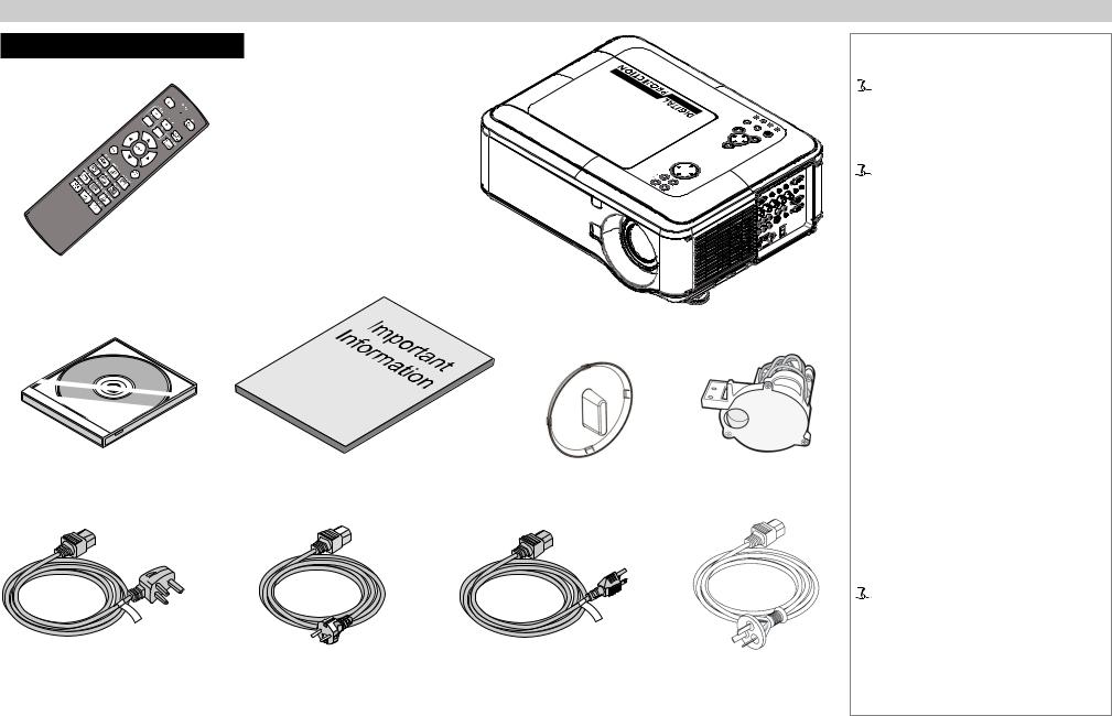
Remote control (112-377)
Projector
User Manual on disc |
Important Information |
Lens cap |
Color wheel |
|
(115-759) |
||||
(114-759) |
|
|
||
|
|
|
Power cable 10A, United |
Power cable 10A, |
Power cable 13A, North |
Power cable, |
Kingdom (102-180) |
Europe (102-163) |
America (102-165) |
China (112-472) |
Installation and Quick-Start Guide
Notes
 Make sure your box contains everything listed. If any pieces are missing, contact your dealer.
 You should save the original box and packing materials, in case you ever need to ship your Projector.
 Only one power cable - dependent on the destination territory - will be supplied with the projector.
Rev D July 2014 |
3 |
Digital Projection E-Vision 6500 Series |
Getting To Know The Projector |
|
|
Getting To Know The Projector |
|
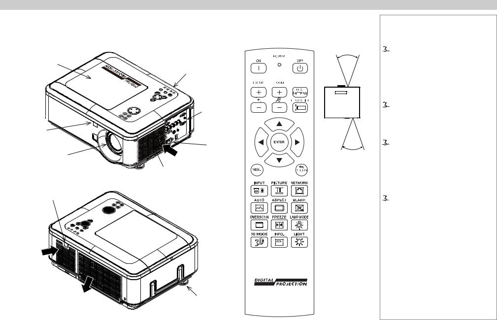
Front and rear views |
Remote control |
Lamp and color wheel cover
Front  infra-red window
Lens
Rear infra-red window
Air inlet
Air filter 
cover Air
outlet
 ZOOM +
|
|
Control |
40° |
|
|
|
panel |
|
|
|
LAMP2 |
|
|
|
OTAU |
LAMP1 |
WARNING |
|
|
RETURN |
SOURCE |
|
|
|
POWER |
|
|
||
|
ENTER |
|
Connection |
|
SHIFT LENS |
|
|
|
|
MENU |
|
|
|
|
– |
|
|
panel |
|
FOCUS |
|
|
|
|
|
|
|
Mains |
40° |
|
|
|
|
|
|
|
Air |
input |
|
|
|
|
Infra-red |
|
|
|
inlet |
|
|
Air filter |
|
reception |
||
cover |
|
|
||
Adjustable
foot
Installation and Quick-Start Guide
Notes
 The projector uses an infra-red remote control.
Some of the controls are duplicated on the projector control panel, as shown on the next page.
 For full details of how to use the controls and the menu system, see the Operating Guide.
 The air filters should be cleaned or changed regularly, depending on the installation environment.
The filters should be changed at the same time as the lamp is changed.
 The projector lens is shipped separately.
Rev D July 2014 |
4 |
Digital Projection E-Vision 6500 Series |
Getting To Know The Projector |
|
||
Control panel and indicators |
|
|
|
|
Some of the controls from the remote control are duplicated on the projector control panel, as |
|
|
|
|
shown on the right. |
|
|
|
|
The CANCEL button has the same function as the RETURN button on the remote control. |
|
|
|
|
Lens |
|
|
||
The SOURCE and AUTO buttons have the same function as the INPUT and AUTO SYNC |
|
|
||
controls |
|
|
||
buttons on the remote control. |
|
|
|
|
|
|
|
|
|
|
|
|
|
|
Menu controls
The Power indicator will show amber when in standby and green when the projector is on, and will flash when the projector is warming up or cooling down.
The Warning indicator will flash to show any error situations.
The Lamp indicators will show which lamp is in use, and whether the projector is in Normal |
Power |
Input |
|
|
|
or Eco mode, and will flash to show lamp status. |
|
|
The chart below shows all possible combinations of indicator lamp color.
Installation and Quick-Start Guide
Notes
 For full details of how to use the controls and the menu system, see the Operating Guide.
|
|
|
|
|
|
|
|
|
|
|
|
|
|
|
|
|
|
|
|
|
|
|
|
|
|
|
|
|
|
|
|
|
|
|
|
|
|
|
|
|
|
|
|
|
|
|
|
|
|
|
|
|
|
|
|
|
|
|
|
|
|
|
|
|
|
|
|
|
|
|
|
|
|
|
|
|
|
|
|
|
|
|
|
|
|
|
|
|
|
|
|
|
|
|
|
|
|
|
|
|
|
|
|
|
|
|
|
|
|
|
|
|
|
|
|
|
|
|
|
|
|
|
|
|
|
|
|
|
|
|
|
|
|
|
|
|
|
|
|
|
|
|
|
|
|
|
|
|
|
|
|
|
|
|
|
|
|
|
|
|
|
|
|
|
|
|
|
|
|
|
|
|
|
|
|
|
|
|
|
|
|
|
|
|
|
|
|
|
|
|
|
|
|
|
|
|
|
|
|
|
|
|
|
|
|
|
|
|
|
|
|
|
|
|
|
|
|
|
|
|
|
|
|
|
|
|
|
|
|
|
|
|
|
|
|
|
|
|
|
|
|
|
|
|
|
|
|
|
|
|
|
|
|
|
|
|
|
|
|
|
|
|
|
|
|
|
|
|
|
|
|
|
|
|
|
|
|
|
|
|
|
|
|
|
|
|
|
|
|
|
|
|
|
|
|
|
|
|
|
|
|
|
|
|
|
|
|
|
|
|
|
|
|
|
|
|
|
|
|
|
|
|
|
|
|
|
|
|
|
|
|
|
|
|
|
|
|
|
|
|
|
|
|
|
|
|
|
|
|
|
|
|
|
|
|
|
|
|
|
|
|
|
|
|
|
|
|
|
|
|
|
|
|
|
|
|
|
|
|
|
|
|
|
|
|
|
|
|
|
|
|
|
|
|
|
|
|
|
|
|
|
|
|
|
|
|
|
|
|
|
|
|
|
|
|
|
|
|
|
|
|
|
|
|
|
|
|
|
|
|
|
|
|
|
|
|
|
|
|
|
|
|
|
|
|
|
|
|
|
|
|
|
|
|
|
|
|
|
|
|
|
|
|
|
|
|
|
|
|
|
|
|
|
|
|
|
|
|
|
|
|
|
|
|
|
|
|
|
|
|
|
|
|
|
|
|
|
|
|
|
|
|
|
|
|
|
|
|
|
|
|
|
|
|
|
|
|
|
|
|
|
|
|
|
|
|
|
|
|
|
|
|
|
|
|
|
|
|
|
|
|
|
|
|
|
|
|
|
|
|
|
|
|
|
|
|
|
|
|
|
|
|
|
|
|
|
|
|
|
|
|
|
|
|
|
|
|
|
|
|
|
|
|
|
|
|
|
|
|
|
|
|
|
|
|
|
|
|
|
|
|
|
|
|
|
|
|
|
|
|
|
|
|
|
|
|
|
|
|
|
|
|
|
|
|
|
|
|
|
|
|
|
|
|
|
|
|
|
|
|
|
|
|
|
|
|
|
|
|
|
|
|
|
|
|
|
|
|
|
|
|
|
|
|
|
|
|
|
|
|
|
|
|
|
|
|
|
|
|
|
|
|
|
|
|
|
|
|
|
|
|
|
|
|
|
|
|
|
|
|
|
|
|
|
|
|
|
|
|
|
|
|
|
|
|
|
|
|
|
|
|
|
|
|
|
|
|
|
|
|
|
|
|
|
|
|
|
|
|
|
|
|
|
|
|
|
|
|
|
|
|
|
|
|
|
|
|
|
|
|
|
|
|
|
|
|
|
|
|
|
|
|
|
|
|
|
|
|
|
|
|
|
|
|
|
|
|
|
|
|
|
|
|
|
|
|
|
|
|
|
|
|
|
|
|
|
|
|
|
|
|
|
|
|
|
|
|
|
|
|
|
|
|
|
|
|
|
|
|
|
|
|
|
|
|
|
|
|
|
|
|
|
|
|
|
|
|
|
|
|
|
|
|
|
|
|
|
|
|
|
|
|
|
|
|
|
|
|
|
|
|
|
|
|
|
|
|
|
|
|
|
Rev D July 2014 |
5 |
||||||||||||||||||||||||||||||||||||||||
Digital Projection E-Vision 6500 Series |
Changing The Lens, Lamps And Color Wheel |
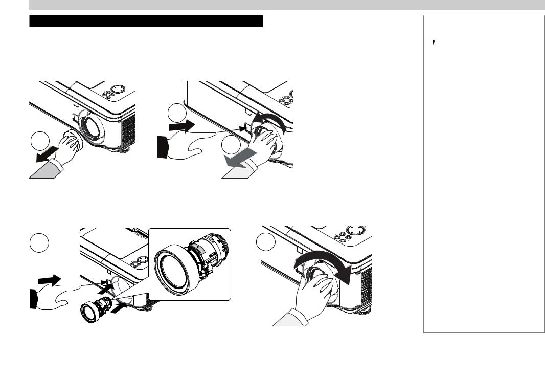
Changing The Lens, Lamps And Color Wheel
Removing the lens
1.Remove the lens cap.
2.Push in the lens release lever, and turn the lens anti-clockwise.
3.Remove the lens.
|
2 |
1 |
3 |
|
Fitting the lens
1.Position the lens so that the label marked ‘O’ is at the top, push in the lens release lever and and gently insert the lens all the way into the lens mount.
2.Turn the lens clockwise until it clicks into place.
1 |
2 |
Installation and Quick-Start Guide
Notes
 Always allow the lamp to cool for 5 minutes before:
-disconnecting the power
-moving the projector
 The projector lens is shipped separately.
Rev D July 2014 |
6 |
Digital Projection E-Vision 6500 Series |
Changing The Lens, Lamps And Color Wheel |
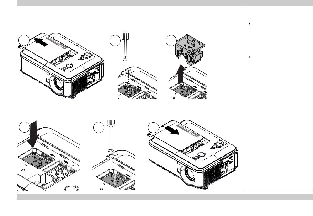
Changing the lamp
1.Slide open the lamp compartment cover as shown in the picture.
2.Unscrew the two captive screws securing the lamp module.
3.Pull firmly upwards on the handle to remove the lamp module.
1 |
2 |
3 |
4. Insert a new lamp module.
5.Fasten the screws.
6.Replace the lamp compartment cover.
4 |
5 |
6 |
Installation and Quick-Start Guide
Notes
 Always allow the lamp to cool for 5 minutes before:
-disconnecting the power
-moving the projector
 The lamp must be changed only by suitably qualified personnel.
 The projector will shut down if the cover is opened whilst in operation.
 The filters should be changed at the same time as the lamp is changed.
Rev D July 2014 |
7 |

Digital Projection E-Vision 6500 Series |
Changing The Lens, Lamps And Color Wheel |
Changing the color wheel
1.Slide open the lamp compartment cover as shown in the picture.
2.Unscrew the four captive screws securing the color wheel.
3.Remove the color wheel.
1 |
2 |
3 |
4. Insert a new color wheel.
5.Fasten the screws.
6.Replace the lamp compartment cover.
4 |
5 |
6 |
Installation and Quick-Start Guide
Notes
 Always allow the lamp to cool for 5 minutes before:
-disconnecting the power
-moving the projector
 The color wheel must be changed only by suitably qualified personnel.
 The projector will shut down if the cover is opened whilst in operation.
Rev D July 2014 |
8 |
Digital Projection E-Vision 6500 Series |
Positioning The Screen And Projector |
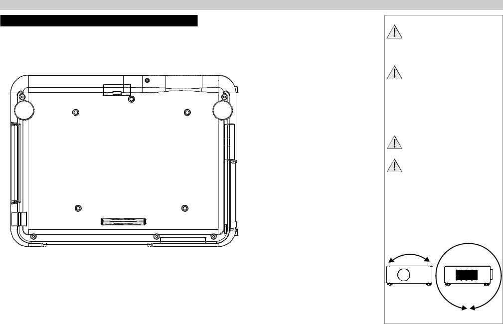
Positioning The Screen And Projector
1.Install the screen, ensuring that it is in the best position for viewing by your audience.
2.Mount the projector, ensuring that it is at a suitable distance from the screen for the image to fill the screen. Set the adjustable feet so that the projector is level, and perpendicular to the screen.
Alternatively, five M4 bolts (max length 12 mm [0.5 in]) can be used to attach the projector to a ceiling mount (optional accessory,).
2
1 |
3 |
4 |
5 |
Location of the ceiling mount holes at the bottom of the projector
Installation and Quick-Start Guide
Notes
Always allow the lamp to cool for 5 minutes before:
-disconnecting the power
-moving the projector
Ensure that there is at least 50cm (20in) of space between the ventilation outlets and any wall, and 10cm (4in) on all other sides.
If ceiling mounting, ensure there is 30cm (12in) of space between the projector and ceiling.
Do not stack the projectors.
Do not tilt the projector more than ±10° from side to side when in use, as this may cause serious lamp failure, damage the lamp module and cause extra cost on replacement.
If you position the projector at an angle, remember to adjust the fan speed accordingly.
±360°
±10°
Rev D July 2014 |
9 |
Digital Projection E-Vision 6500 Series |
Operating The Projector |
Operating The Projector
Switching the projector on
•Connect the power cable between the mains supply and the projector. Switch on at the switch next to the power connector.
•Wait until the self-test has completed and the Power indicator on the projector control panel shows amber. The lamp will be off and the projector will be in STANDBY mode.
•Press on the control panel or POWER ON on the remote control.
The Power indicator on the control panel will flash green for a few seconds whilst the lamp comes up to full brightness. When the projector is ready for use, the Power indicator will show steady green.
Selecting an input signal or test pattern
Input signal
•Connect an image source to the projector. The signal should be automatically detected by the projector, and should be displayed within a two or three seconds.
•If more than one signal is connected, then select the image you want to display: Press SOURCE on the control panel to cycle through the inputs,
or press INPUT on the remote control, then  or
or  to cycle through the inputs.
Test pattern
If you have no image source connected to the projector, then you can display a test pattern instead: Press TEST PATTERN on the remote control, then  or
or  to cycle through the patterns, or select a Test Pattern from the Installation menu.
Installation and Quick-Start Guide
Notes
Before switching on the projector for the first time, make sure
the electric circuit is grounded. Poor grounding may damage the projector.
Always allow the lamp to cool for 5 minutes before:
-disconnecting the power
-moving the projector
 For full details of how to connect an image source to the projector, see the Connection Guide.
 For full details of how to use the controls and the menu system, see the Operating Guide.
Rev D July 2014 |
10 |
Digital Projection E-Vision 6500 Series |
Operating The Projector |
Adjusting the lens
Zoom
•Use the ZOOM +/− buttons on the control panel or on the remote control to adjust the lens so that the image fills the screen.
Focus
•Use the FOCUS +/− buttons on the control panel or on the remote control to adjust the lens until the image is sharp.
Shift |
|
|
|
|
|
|
|
• Use the LENS SHIFT buttons |
, |
, |
and |
on the control panel to adjust the |
|||
position of the image, |
|
|
|
|
|
|
|
or press the LENS SHIFT button on the remote control then use |
, |
, |
and |
||||
to adjust the position of the image. |
|
|
|
|
|
|
|
Adjusting the image
Orientation
•Use the Projection Mode settings, in the Installation Menu.
Aspect ratio
•Press the ASPECT button on the remote control to cycle through all the available settings.
or use the Aspect Ratio setting in the Setup Menu.
Picture
•Press PICTURE on the remote control or use the menu controls, to open the Picture Menu.
Use the sliders in the Picture menu to adjust the brightness, contract etc.
Installation and Quick-Start Guide
Notes
 For full details of how to use the controls and the menu system, see the Operating Guide.
Rev D July 2014 |
11 |

Digital Projection E-Vision 6500 Series |
Operating The Projector |
|
Switching the projector off |
|
|
• Press |
on the control panel or STANDBY on the remote control, then press the button a second time within 5 seconds to confirm your |
|
intention to switch off.
The lamp will go off, and the Power indicator on the control panel will flash amber for a few seconds whilst the lamp cools. The Power indicator on the control panel will then show amber and the projector will be in Standby mode.
•Switch off at the switch next to the power connector. Disconnect the power cable from the projector.
Installation and Quick-Start Guide
Notes
 Always allow the lamp to cool for 5 minutes before:
-disconnecting the power
-moving the projector
Rev D July 2014 |
12 |

CONNECTION GUIDE
E-Vision 6500 Series
High Brightness Digital Video Projector
|
|
LAMP2 |
TO |
AU |
LAMP1 |
|
|
|
RETURN |
|
ES |
|
|
|
|
|
ENTER |
WARNING  POWER
POWER
MENU
SHIFT |
LENS |
|
 ZOOM
ZOOM  +
+
 –
–
 FOCUS
FOCUS
Rev D July 2014

Digital Projection E-Vision 6500 Series |
IN THIS GUIDE |
IN THIS GUIDE |
|
Signal Inputs And Outputs.............................................................................. |
15 |
Computer 1................................................................................................................. |
15 |
Computer 2................................................................................................................. |
15 |
Computer 3................................................................................................................. |
15 |
Component................................................................................................................. |
15 |
Video or S-Video........................................................................................................ |
15 |
Monitor Out................................................................................................................ |
15 |
Supported Signal Input Modes...................................................................... |
16 |
Control Connections......................................................................................... |
18 |
Screen Trigger............................................................................................................ |
18 |
USB Service Port....................................................................................................... |
18 |
Wired Remote Control............................................................................................... |
18 |
RS232.......................................................................................................................... |
18 |
LAN............................................................................................................................. |
18 |
Wiring Details...................................................................................................... |
19 |
Signal inputs and outputs......................................................................................... |
19 |
Monitor video output (VGA)............................................................................................. |
19 |
Computer 1 video input: analog computer (VGA)............................................................ |
19 |
Computer 2 video input: RGBHV, RGsB or YCbCr......................................................... |
19 |
Computer 3 video input: DVI-D........................................................................................ |
20 |
Component video input.................................................................................................... |
21 |
Video input....................................................................................................................... |
22 |
S-Video input................................................................................................................... |
22 |
Control connections.................................................................................................. |
23 |
Screen Trigger output...................................................................................................... |
23 |
RS232 Serial control input............................................................................................... |
23 |
Wired remote control connection.................................................................................... |
23 |
LAN connection............................................................................................................... |
24 |
Connection Guide
Rev D July 2014
 Loading...