

Page 1

Operators Manual
Fort Atkinson, Wisconsin USA
Panningen, The Netherlands
www.digi-star.com
D3664-US Rev G June 2007
Page 2

RF DataLink
D3664-F
Page 3

Operators Manual
RF DataLink Setup 1
Sequence of Operations .............................................. 1
Registering the Software.............................................. 1
Radio Installation and Setup ........................................ 1
Radio Antennas ........................................................... 2
Fresnel Zone................................................................ 3
Radio Interference ....................................................... 3
Standard Range Setup ................................................ 3
Extended Range Setup................................................ 4
USB Black Box Installation .......................................... 5
Passwords ................................................................... 5
Setting the File Paths................................................... 5
Entering Mixer Data ......................................................... 7
Adding Mixers .............................................................. 7
Determining the System Defaults. ............................... 8
Process Selection ........................................................ 9
Pen Data Type............................................................. 9
Make As Fed Data File ................................................ 9
Zone Control ................................................................ 10
Send Mill Demand ....................................................... 10
Pen Delivery List Source.............................................. 11
Batch Number Included ............................................... 11
Timing .......................................................................... 11
Setting the Timing........................................................ 11
Weight Tolerances....................................................... 12
Pen Delivery Weight Tolerances.................................. 12
Operator Acknowledge ................................................ 12
Ration Weight Delivery Tolerances.............................. 13
Operator Acknowledge ................................................ 13
Split Load Minimum Balance ....................................... 13
Operator Interface........................................................ 14
Modify Recipe .............................................................. 15
Modify Pen Enabled..................................................... 15
Manual Load Making ................................................... 15
Wait for Acknowledge .................................................. 15
Bunk Reader .................................................................... 16
Select Bunk Reader Type ............................................ 16
Pen Feeding..................................................................... 17
Pen Delivery Mode ...................................................... 17
Optimize Load to Mixer/Optimize-Split Pens................ 17
Find Pens to Fit............................................................ 18
Mixer Loading .............................................................. 19
Print Mixer Load Sheet ................................................ 19
Weigh Units ................................................................. 19
D3664
Page 4

RF DataLink
Determining the Load Size for the Mixer...................... 19
Feedings To Mixer ....................................................... 20
Transfer Type .............................................................. 20
Full Load Delay............................................................ 20
Variable Mix Control..................................................... 21
Radio Settings ............................................................. 21
Datalink Reserve Channel ........................................... 22
Base Radio Type ......................................................... 22
Installation Test............................................................ 22
Operating the RF DataLink 22
Quantity of Radios to be Used ..................................... 22
Importing the Feeding Data ......................................... 23
Starting the Process .................................................... 23
How the Process Works............................................... 23
Modifying Ration Data.................................................. 25
Changing Ingredients................................................... 25
Deleting Ingredients..................................................... 26
Adding Ingredients....................................................... 27
Modifying Pen Data ..................................................... 27
Changing Pen Rations................................................. 28
Deleting Pens .............................................................. 28
Adding Pens ................................................................ 29
Changing the Pen Order .............................................. 29
Putting an In-Process Pen back in the Feeding ........... 30
Deleting Records ......................................................... 30
Viewing the Error Log .................................................. 31
Test Communications .................................................. 32
Indicator Status............................................................ 32
Reliability Meter ........................................................... 33
Repair Parts – Std. Antenna ........................................ 34
Repair Parts – Extend Range Antenna........................ 35
Page 5
Operators Manual
RF DataLink Setup
Sequence of Operations
After installing your software, please follow this section to setup the RF DataLink for use. It
is important that you follow along with this sequence.
Registering the Software
Once the software has been installed, it must be registered. Contact Digi-Star to obtain
your registration code. The code is case sensitive; all letters must be entered in upper
case.
Radio Installation and Setup
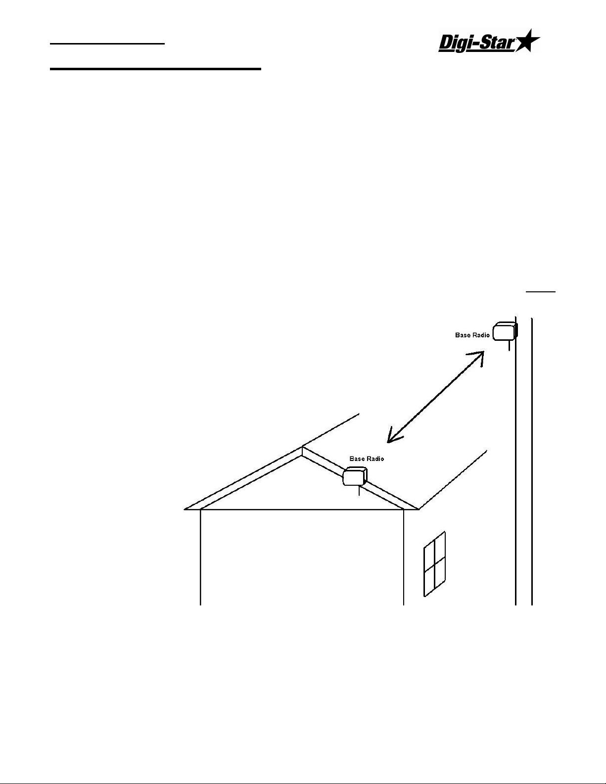
When installing the base radio; make sure the “ram mount” is fully extended away from the
mounting surface.
For greater radio communication and range mount the radio in the highest position that it is
visible from the ground or were the mixers are being loaded. Mount the radio in either
position like the illustration. On the corner of the office or on a utility pole.
D3664
1
Page 6
RF DataLink
Radio Antennas
The location of the antennas is critical. Check the installation of the antennas and the
antenna location.
Indicator and Truck Mounted Antenna: Truck Mounted Antenna, mount the antenna
outside, on the top of the cab, in the center of the roof. Do not modify the cable between
Truck Mounted Antenna and the indicator.
Yes No Are any building near the Base Station Antenna metal?
Yes No Are any metal structures located between the Base Station Antenna and
the mixers?
Yes No When standing at the Base Station Antenna, can you see the mixer?
Yes No Have any of the antenna cables been modified?
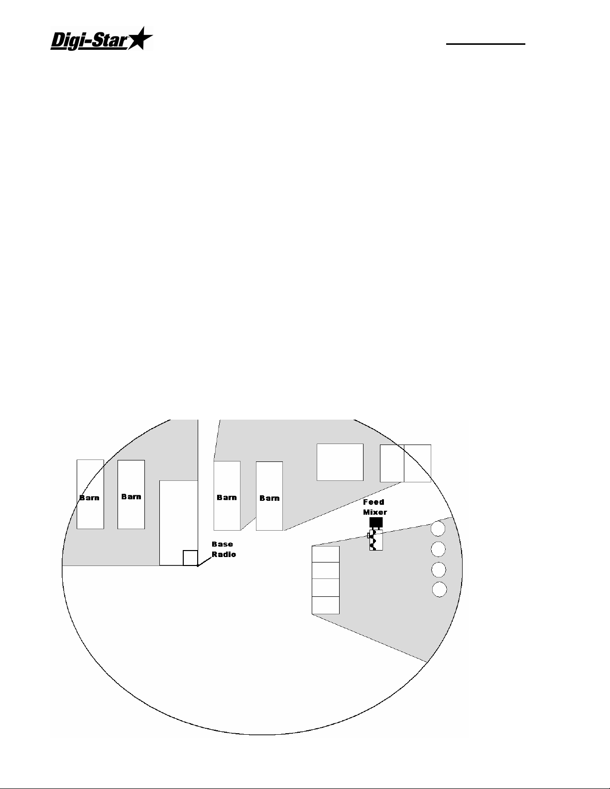
Radio Range:
The picture below shows how radio range would be affected by obstructions like metal
barns or earth. The gray areas show poor radio signal. If the radio is mounted higher, this
may improve radio range.
2
Page 7
Operators Manual
Fresnel Zone
The Fresnel Zone can be thought of as a football-shaped tunnel between two sites that
provides a path for RF signals.
In order to achieve the greatest range, the football-shaped path in which radio waves travel
must be free of obstructions. Buildings, trees or any other obstacles in the path will
decrease the communication range. If the antennas are mounted just barely off the ground,
over half of the Fresnel Zone ends up being obstructed by the earth resulting in significant
reduction in range. To avoid this problem, the antennas should be mounted high enough off
the ground so that the earth does not interfere with the central diameter of the Fresnel Zone.
Minimal height of base radio:
Range Distance Height
1000 ft (305 m) 15 ft (4.6 m)
1 Mile (1.61 km) 25 ft (7.6 m)
1.5 Miles (2.42 km) or more 45 ft (13.7 m)
If you do not have enough cable from the computer to the radio there are different cable
lengths that Digi-Star offers, or you would like a higher powered antenna, contact Digi-Star.
Standard length is 50 ft / 15.25 m (RS-232). Extended length is 150 ft / 45.75 m (RS-422)
or custom lengths are available (150+)
Radio Interference
There are many types of wireless networks or (WIFI) and some can interfere with the
DataLink radio. If DataLink is still showing radio interference, check the WIFI network
number. Changing this number can correct for radio interference. For further information
about WIFI, check the website of the brand of your radio. 802.11 2.4GHZ use channels 1 –
6 and 13 & 14.
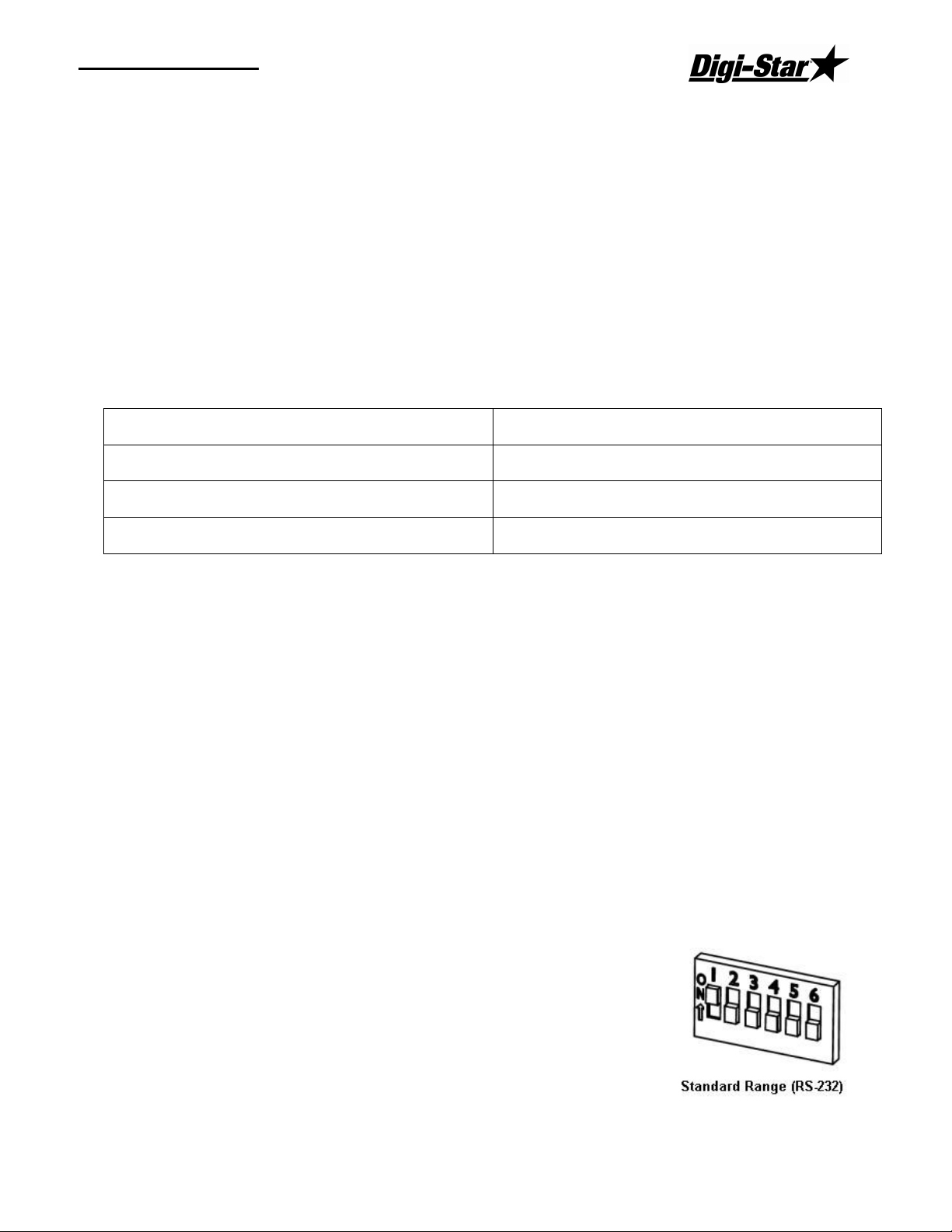
Standard Range Setup
When using the standard range kit, connect the DB9 serial connector to either a serial port on
the PC or use the USB to Serial adapter included and connect the
12VDC power supply to the cable. The base radio is shipped from
Digi-Star setup for standard range. The switch settings on the
radio are set to the picture to the right: Verify this if you are not
able to communicate with the base radio
D3664
3
Page 8
RF DataLink
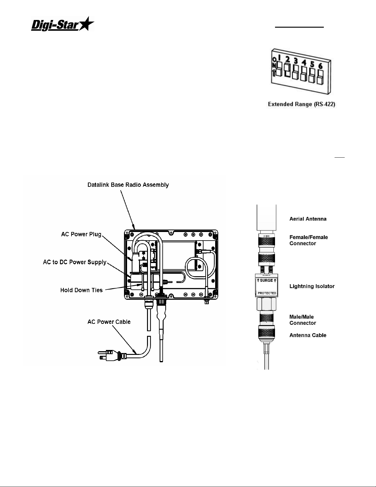
Extended Range Setup
If you are using the extended range radio kit (RS-422) you must
go to System, then Defaults, and select [Radio Settings]. Under
Base Radio Type, select [Extended Range Base Radio (RS-422).
RF Datalink will then pause while looking at the radio for the new
settings.
Next open the housing of the base radio. There is a bank of dip
switches on the right side,
Set switches as the picture on the right:
Install the AC/DC power transformer into the base radio box and run AC power into the unit
as shown. When attaching the female plug to the power cord, remove green ground wire
and attach either of the remaining two wires to either terminal. AC/DC adaptor is not
polarized.
Antenna Assembly
4
Page 9
Operators Manual
USB Black Box Installation
Plug in the Black box into a USB port. Windows will detect
the Black box and at this point Insert the driver CD.
Follow the Windows prompts.
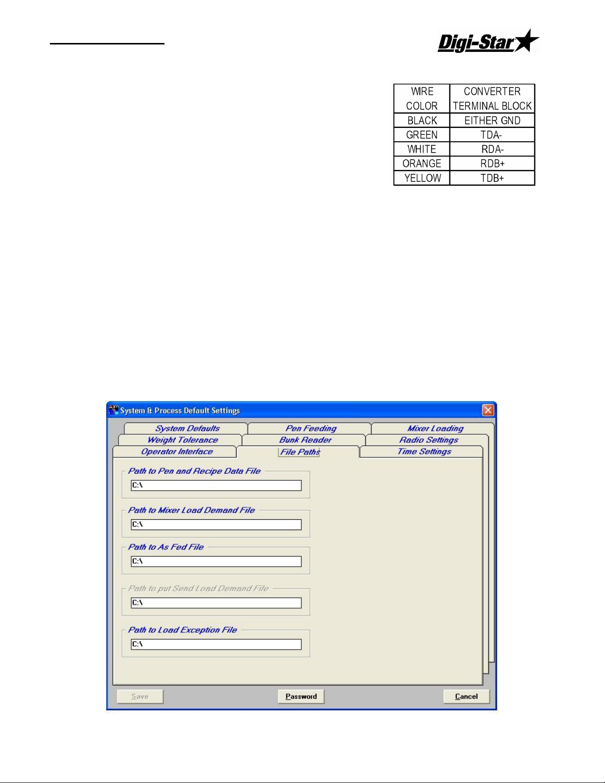
Open the end cover of the Black Box and install the wires
as follows:
Passwords
Many of the settings under the System, Defaults menu are critical to the overall operation of
the RF DataLink program. To protect these settings, you have the ability to set a password
that will prevent unauthorized access to these settings. Once a password has been set on
any default screen, it is set for all default screens.
As with all passwords, please be sure to record your password in a safe place and guard it
from other users. Should you lose or forget your password, you will have to call Digi-Star
to have it reset.
Setting the File Paths
RF DataLink shares files with other software. As such, each program must know where to
send and where to look for these files.
D3664
5
Page 10

RF DataLink
To set the File Paths, from the main menu select [Systems], [Defaults] and [File Paths].
This will display the File Path screen.
1. Path to Pen and Ration Data Files - this is the data that is transferred from the third
party software or TMR Tracker. Ration mixes and pen calls.
2. Path to Mixer Load Demand File - Not used in this application.
3. Path to As Fed File - this is the data that is transferred from the RF DataLink to the third
party software. Completed Ration mixes and pen feedings.
4. Path to put Send Load Demand File - this option will send a file out to a mill demand to
show the total load size of the next load sent to the mixer.
5. Path to Load Exception File - this is the error log for any weight tolerance that you set.
This data does not have to be transferred from the PC running the RF DataLink program.
If you are not using a network, the path settings for 1 and 3 would be set to C:\. If you are
using a network, set the paths to whatever your network drives have been set too.
If you setup a file such as ERROR above, that Folder must exist before you can save the
settings. The RF DataLink will not create the Folder for you.
When complete, click [Save].
6
Page 11

Operators Manual
Entering Mixer Data
Adding Mixers
To access the Mixers screen, select Mixers from the File Menu. This will display the Mixers
screen. In a new installation, the Mixer screen will be blank.
Select the Add button to add a new mixer. Enter the Mixer number 1-12 (this number
should match the Scale Number).
D3664
7
Page 12
RF DataLink
Mixer Number – a two-digit number to identify the Mixer.
Description – a detailed Mixer description. The first letter of this may be displayed on the
Process Screen.
Radio Channel – the radio number will be set on the EZ indicator. To view or change the
number use the direct access number (231). Press (Select) to change the number, and
press (On) to save. Make sure if you are using two or more mixers that you don’t use the
same radio ID.
Mixer Size – Enter the lbs/Kg per cubic foot/Meter or enter the load number. The load
number is used with Bunk reader programs.
Active - to signify that the Mixer is available for feeding, click on [Yes] in the Active box.
Clicking on [No] will make the Mixer un-available for loads or feeding.
Acknowledge – Acknowledge – This option is used to send a message to the scale if the
operator would like to receive another load. If the operator does not press the Tare key
within 10 seconds at the scale, Datalink will continue to other mixers.
To save your entries, click [Save].
If you are using static mixers/dump boxes and delivery wagons, go to the default setting to
change this setting.
Determining the System Defaults.
The system defaults control how you process your feedings. These settings can help to
further optimize your feeding process. Please take some time to read and understand these
settings and their affect on your feeding process.
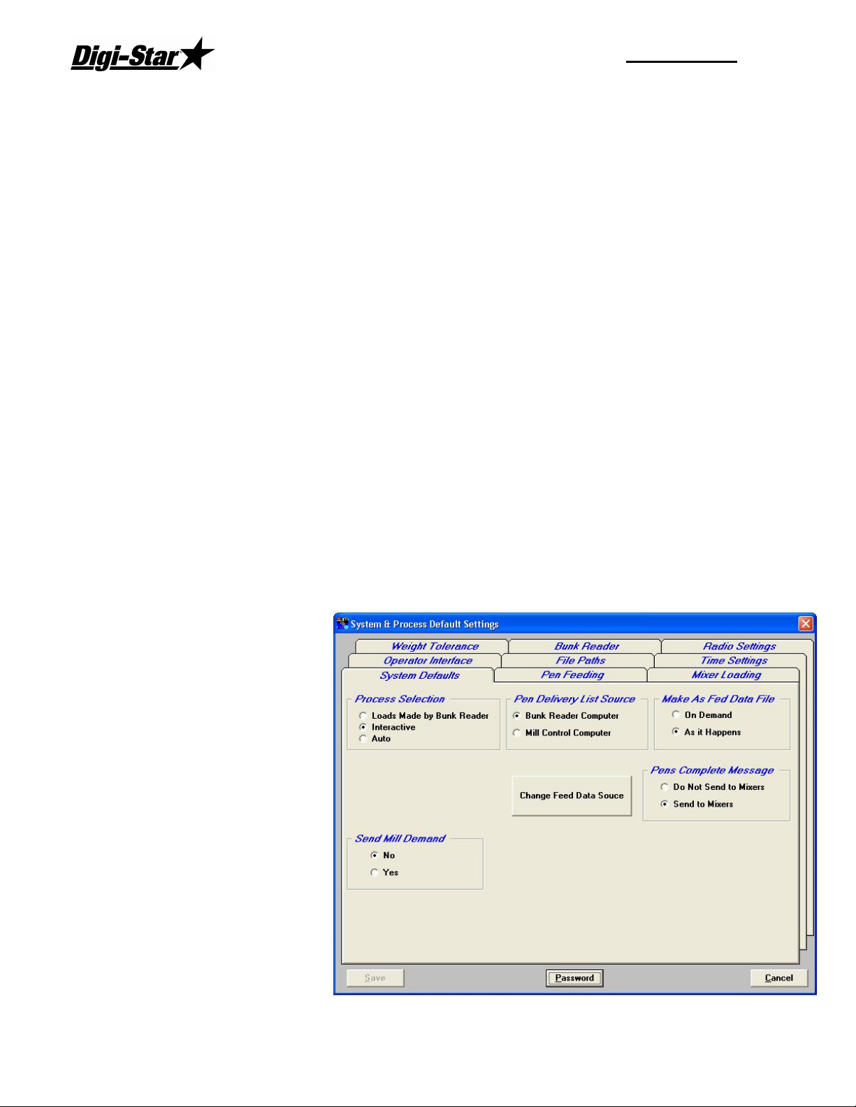
To set the System Default Settings, from the main menu select [Systems], [Defaults], and
[System Defaults].
The system defaults screen
contains all the choices
available to change the
manner in which the RF
DataLink processes your
feedings.
8
Page 13

Operators Manual
Process Selection
Interactive – this process selection allows the input of an external load demand to make
loads for your feed mixers. This external demand will typically
be generated from a mill software package. This selection also
allows an operator at the PC running the RF DataLink to
manually enter loads.
If you do not have a mill software package or do not want to
interface the mill and the RF DataLink, you must have an
operator running the RF DataLink in order to use this selection.
Auto – this process selection will automatically make and send loads to your mixer without
operator intervention. You will still have the ability to send manual loads if you elect to turn
that option on. This selection allows the RF DataLink to operate independent of user
intervention or input.
Notes: [Auto] is the typical selection for most installations. Manual is not an available selection.
When you have completed your entries, click [Save].
Pen Data Type
Single Pen – this mode will send a single pen load at a time to
your mixer. One pen, one load. This mode can be used if your
mixer is undersized for your operation and cannot hold enough
feed to process more than one pen at a time.
(This mode is the least efficient.)
Multiple Pens – this mode will send multiple pens to your mixer based on your vehicles
size and how much of a particular ration it can hold. Multiple pens, one load.
(This mode is the most efficient and is the typical setting for most installations.)
When you have completed your entries, click [Save].
Make As Fed Data File
The As Fed Data File is the completed loading and feeding data
that is transferred to third party software. This file can be sent in
two ways;
On Demand – this selection sends the data file on a demand
basis. When a completed load is received by the RF DataLink program, the file is stored
until a demand for the file is received. The file is then written to the file path set for the As
Fed File. The demand is triggered by selecting Make As Fed File from the File main menu.
D3664
9
Page 14

RF DataLink
As it Happens – this selection writes the data file as it is
received. When a completed load is received by the RF
DataLink program, it is immediately written to the file path
set for the As Fed File.
When you have completed your entries, click [Save].
Zone Control
This setting determines whether the ability to set up zones and
assign pens and Mixers to zones is turned on.
The Zone Control allows you to split your pens into separate
Zones and to assign specific feed mixers to those Zones. If you
set this to On, you must include the Zone field in the pen data being sent. Additionally, you
must set the Zone for the Mixers. To access that
setting, from the main menu, select [Files] and
[Mixers]. If you have already setup Mixers in this
file, click on Modify to assign the Zones.
In the example shown, the Mixer 11 has been set
to service Zones 01 and 02.
By setting up Zones, you limit the pens assigned
to a Mixer to only those assigned to its Zone. You
can override this setting by sending a load outside
of the Mixer’s Zone manually. The RF DataLink
will ask you to verify that you want to send a load
outside of the Mixers Zone. If you select [Yes],
the load will be sent.
When you have completed your entries, click
[Save].
Send Mill Demand
This option is only used of the site has a mill batching
software program that will import batch load sizes. This
option will export the load size that was sent to the next ready
mixer.
10
Page 15

Operators Manual
Pen Delivery List Source
This option sets the source of where RF DataLink will look for
the pen delivery information. From either a bunk reader
program or a mill program. This option will have different
formats in how it will read in the pen delivery information. Be
sure to set this correctly.
Batch Number Included
This option will be used if the third party program sends over
a batch number in the W2T_Pen.dat file.
Timing
The Timing Settings allow you to
optimize the efficiency of the radio
communications within the RF
DataLink program.
The RF DataLink continuously
searches for Mixers. To optimize
this process you can take into
consideration the time required for a
Mixer to service the pens.
Example: It takes your operator 10
minutes to load the ration, 5 minutes
to mix and another 5 minutes to
drive to pen 3. That being the case,
you can tell the RF DataLink
program to ignore the Mixer for the
initial 20 minutes that it will take just
to get to the pen.
Setting the Timing
To set the Timing, from the main menu select [Systems], [Defaults], and [Timing].
Enter the pen numbers and the time delay in seconds. In this example, the time delay for
pens 0 to 5 is 5 minutes (60 seconds x 5).
These settings are optional and do not have to be used.
When you have completed your entries, click [Save].
D3664
11
Page 16

RF DataLink
Weight Tolerances
The weight tolerance
settings allow you to
establish an accuracy
level for the loading and
feeding of your rations
and pens. This tolerance
is applied to each
ingredient in a ration and
each pen in a load. The
tolerance is then used to
compare the call weight
and the actual weight. If
the result is more than the
tolerance established, an
error message is
displayed showing the
resulting error and an
error log is created.
Pen Delivery Weight Tolerances
To set the Weight Tolerances, from the main menu select [Systems], [Defaults], and [Weight
Tolerance].
To set the Pen Delivery Tolerances, first set the Pen Delivery Validate to [On].
To set the Tolerance Weight for the pen deliveries, select the feeding number and enter a
tolerance in pounds. You can set different tolerance weights for each feeding.
Example: You can have a relatively large window (tolerance) for the 1st feeding of the day
when the goal is to get feed in front of the animals, where you may have a much tighter
window (tolerance) in the afternoon when the goal is to get as close to the total amount for
the day as possible.
When you have completed your entries, click [Save].
Operator Acknowledge
This setting determines whether the error message showing the feeding error must be
acknowledged by an operator before the RF DataLink program continues. If you select
[Yes], an operator must acknowledge the error before the RF DataLink program will
continue. If you select [No], the error message will time out after 10 seconds and the RF
DataLink program will continue.
Either choice will write the error to an error log if you have turned on the Pen Delivery
Validate.
When you have completed your entries, click [Save].
12
Page 17

Operators Manual
Ration Weight Delivery Tolerances
To set the Ration Weight Tolerances, from the main menu select [Systems], [Defaults], and
[Weight Tolerance].
To set the Ration Weight Tolerance, first
turn the Ingredient Load Validate [On].
To set the tolerance weight, enter the
tolerance weight in pounds. This is a
global setting that will apply to all
ingredients loaded.
Example:
Tolerance = 500 pounds
Call weight = 4000 pounds
Actual loaded weight = 3600 pounds
Result = No error message
Actual loaded weight = 3400 pounds
Result = error message
When you have completed your entries,
click [Save].
Operator Acknowledge
This setting determines whether the error message showing the loading error must be
acknowledged by an operator before the RF DataLink program continues. If you select
[Yes], an operator must acknowledge the error before the RF DataLink program will
continue. If you select [No], the error message will time out after 10 seconds and the RF
DataLink program will continue.
Either choice will write the error to an error log if you have turned on the Ingredient Load
Validate.
When you have completed your entries, click [Save].
Split Load Minimum Balance
To set the Split Load Minimum Balance setting, from the main menu select [Systems],
[Defaults], and [Weight Tolerances].
The Split Load Minimum Balance determines whether the remaining amount of a split load
will be built
D3664
13
Page 18

RF DataLink
Example: You had a 4000-pound call weight to deliver to pen 1 and a split load occurred
that left 200 pounds to be fed to pen 1. You could set the split load minimum balance to
300 pounds. In this case, the remainder of the call for pen 1 would not be fed.
This setting is typically set to 50
pounds.
To set this, enter the amount in pounds
that you want to set as your split load
minimum. This setting is feeding
specific. Repeat as needed for each
feeding. Each feeding can have
different settings.
When you have completed your
entries, click [Save].
Operator Interface
To access the operator interface, from the main menu select [Systems], [Defaults], and
[Operator Interface].
14
Page 19

Operators Manual
Modify Recipe
To set the Modify Rations Enabled Selection, from the main
menu select [Systems], [Defaults], [Processing]. This will display
the Process Settings screen.
This selection determines whether you will allow rations to be
modified in the RF DataLink program. If you select [Yes], you
will be able to edit a ration.
Selecting [No] will not allow ration modification within the RF DataLink program.
Ration data is created and sent from third party software. If you edit a ration within the RF
DataLink program, you will not be able to obtain accurate reporting on that ration unless you
make the identical changes within third party software.
Modify Pen Enabled
To set the Modify Pens Enabled Selection, from the main menu
select [Systems], [Defaults], [Processing]. This will display the
Process Settings screen.
This selection determines whether you will allow pens to be
modified in the RF DataLink program. If you select [Yes], you will
be able to edit a pen.
Selecting [No] will not allow pen modification within the RF DataLink program.
Pen data is created and sent from third party software. If you edit a pen within the RF
DataLink program, you will not be able to obtain accurate reporting on that pen unless you
make the identical changes within third party software.
Manual Load Making
To set the Manual Load Making Selection, from the main menu
select Systems, Defaults, Processing. This will display the
Process Settings screen.
This selection determines whether you will allow a user at the RF
DataLink to enter a manual load. In the Auto Process, the RF
DataLink will automatically make your loads, if you select [Yes] to allow manual load
making, an operator can override the RF DataLink and force the next load.
If you select No, manual load making is disabled.
Wait for Acknowledge
To set the Wait for Acknowledge Selection, from the main
menu select Systems, Defaults, Processing. This will
display the Process Settings screen.
This setting determines whether the RF DataLink program
will wait for a response from an operator for any programgenerated message.
If you select [Yes], an operator must respond to the message before the program will
resume. If you select [No], the message will automatically time out after 10 seconds and the
program will resume.
D3664
15
Page 20

RF DataLink
Bunk Reader
Select Bunk Reader Type
To set the Bunk Reader type, from the main menu select Systems, Defaults, and then the
Bunk Reader tab.
This option will determine the format in how the data will be received into the RF DataLink
software. You will only use the standard TMR Tracker File Type if you are using TMR
Tracker software to make your batch and pen files.
16
Page 21

Operators Manual
Pen Feeding
Pen Delivery Mode
To set the Pen Delivery Mode, from the main menu select Systems, Defaults, and then the
Pen Feeding tab.
Single Pen – this mode will send a single pen load at a time to the
mixer. One pen, one load. This mode can be used of your mixer is
undersized for your operation and cannot hold enough feed to
process more than one pen at a time. This mode is least efficient.
Multiple Pens – this mode will send multiple pens to your mixer based on your mixers size
and how much of a particular ration it can hold. Multiple pens, one load. This mode is most
efficient and is the typical setting for most installations.
Optimize Load to Mixer/Optimize-Split Pens
To set the Optimize/Split Pens Selection, from the main menu
select Systems, Defaults, and then the Pen Feeding tab.
This setting determines whether the RF DataLink will split pens in
order to fill your mixer to capacity. When you select [Yes], the RF
DataLink program will maximize the load in your feed mixer and
split pens as needed.
Example;
D3664
17
Page 22

RF DataLink
Maximum load size is 8,000 pounds of Ration 1
Pens and call weights: Pen 1 2,000
Pen 2 2,000
Pen 3 2,000
Pen 4 3,000
Pen 5 1,000
If you select [Yes], the load would total 8,000 pounds and would feed pens 1, 2, 3 and 1,000
pounds of the call weight for pen 4. The next load that is built would feed the remaining
2,000 pounds.
This setting is typically set at [Yes].
Find Pens to Fit
To set the Find Pens to Fit Selection, from the main menu select
Systems, Defaults, and then the Pen Feeding tab.
This setting is only available if you have selected [No] at the
Optimize Split Pens selection.
This setting determines how the RF DataLink will optimize your
feeding when you elect Not to maximize the load in your feed
mixer. The system can search the pen list to find smaller pens to get the load as close to
the maximum as possible or can be set to stop at the first pen that will exceed the maximum
load size.
Example;
Maximum load size is 8,000 pounds of Ration 1
Pens and call weights:
Pen 1 2,000
Pen 2 2,000
Pen 3 2,000
Pen 4 3,000
Pen 5 1,000
With the option set to Look for smaller Pens that Fit, the load would total 7,000 pounds
and would feed pens 1, 2, 3 and 5.
With the option set to Stop at first pen that is over, the load would total 6,000 pounds and
would feed pens 1, 2 and 3.
When you have completed your entries, click [Save].
18
Page 23

Operators Manual
Mixer Loading
Print Mixer Load Sheet
To set the Print Load Sheet Selection, from the main menu
select Systems, Defaults, and then the mixer loading tab.
This selection determines whether a Load Sheet will be printed
for each load sent to the EZ Indicator in your mixer. The Load
Sheet contains the ration loading and pen feeding information as
loaded into the EZ Indicator.
This setting is typically set to [No].
Note: You must have a printer connected to the PC running the RF DataLink in order to use
this setting. If you select [Yes] and do not have a printer connected, the RF DataLink
program will not process another load until you either connect the printer or change the
setting to No.
Weigh Units
To set the Weigh Units, from the main menu select Systems,
Defaults, and then the Mixer Loading tab.
This selection sets the weigh units of the RF DataLink to either
pounds or kilograms. Be sure that the EZ indicator is set to the
same weigh units.
Determining the Load Size for the Mixer
To set the Load Size, from the main menu select Systems,
Defaults, and then the Mixer Loading tab.
D3664
19
Page 24

RF DataLink
This setting is used by RF DataLink to determine how much of a particular ration can be
loaded into your feed mixer.
This setting must be set to Mixer Volume.
Feedings To Mixer
To set how the feedings are sent
to the mixer, from the main menu
select Systems, Defaults, and then
the Mixer Loading Tab.
This option allows the PC operator
to either send one load to the
mixer at a time, send the entire
feeding or feedings for the day to
the mixer and allow the PC to only
send the pens for that load, or
send the entire feeding or feedings
for the day to the mixer and have
the scale operator control what pens get the ration. This option is most useful if the ration is
most likely not to change over the coarse of the feeding period. Or the feed mixer is out of
range of the base radio for more than 2 loads.
When you select, [All Loads at one time. PC controls loads] or [All pens and Recipes at one
time to the mixer. Mixer controls the loads]. The “Distribute All Pens to All Mixers” option
will appear. This option is set to [No] if the mixers have zones assigned to them. It will only
send the correct zone to the correct mixer if the option is set to [NO].
Transfer Type
This option determines how the feed data will be sent to
either a stationary mixer/box or a standard mixer system.
When using the stationary mixer/box Datalink will send the
ingredient loading information to the stationary mixer/box
and the pen unloading information to the delivery
mixer/box. When a load is compete at the stationary
mixer/box, Datalink will send a message to the delivery
mixer/box of what stationary mixer/box to pick up the load.
When using a stationary mixer/box and delivery mixer/box
you also have an option to send what pens are in the load
to be displayed at the stationary mixer/box.
Full Load Delay
This option is used with a bunk reader program. If the bunk
reader program sends pens to Datalink when new pens are
20
Page 25

Operators Manual
available, Datalink will wait until there are pens to make a complete
load to send to a mixer.
Variable Mix Control
This option is used when sending a mix time to the mixer/box.
When set to “Yes” Datalink will adjust the mix time based on a
10,000 lbs or kg load. If the mix time is set for 5:00 minutes
and the load is 15,000, the mix time will increase to 7:30
minutes.
Radio Settings
D3664
21
Page 26

RF DataLink
Datalink Reserve Channel
Radio Channel – The radio channel will normally be set to 7. This number can be changed
incase you have neighboring sites causing interference.
Radio Retries – This number is used to by the base radio recheck the EZ indicator to make
sure that the feed data sent is correctly.
Base Radio Type
Standard Range Base Radio (RS-232) – Set this option if the base radio is the standard
range.
Extended Range Base Radio – Set this option if the base radio is the extended range, the
PC will have the “Black Box” signal converter.
Installation Test
This option is useful when testing the range of the radio system. To use this option set
option to YES and save it.
Next set the scale to test mode, to change this enter short cut number (457) and press
(Select). Change the option to (Yes) by pressing (Select) and then press (ON) to save.
Operating the RF DataLink
Now send feedings to DataLink and start the process. DataLink will send feeding data to
the scale. and then press the (Recipe) key to send the data back to the PC. This will repeat
until the number of feeding are gone.
Quantity of Radios to be Used
You may use up to 24 channels. In order to use more than 12 channels you must contact
Digi-Star for an unlock code. (920) 563-1400
22
Page 27

Operators Manual
Importing the Feeding Data
To import the feeding data, select Process from the main menu of the RF DataLink
program. The program will automatically read the feeding data. A screen called Importing
Pen File will be displayed while the feeding data is being read. When the file has been
completed, the Importing Pen File box will be removed from the screen. The second
window will now display the Feeding Number, Ration, Zone, Call Weight, Millmix and
Externally Loaded amounts as shown:
The Call Weight is the total amount of that ration to be fed for that feeding.
Millmix refers to the amount of that ration that is mixed at a mill.
Ex. Loaded is the amount of that ration that will be loaded at the Mixer.
If the RF DataLink program is already running in the Process mode, the program will
automatically read any new feeding data sent from third party software. The RF DataLink
program looks for feeding updates between each conversation with the EZ Indicator.
Starting the Process
Once the feeding data has been read into the RF DataLink program, you can start the
actual feeding process by clicking on the Start button on the Process screen. The feeding
process will not begin until you click on the Start button.
How the Process Works
The feeding process in the RF
DataLink program begins with
a check of all available Mixers.
The program initiates radio
communication with each
Mixer. It determines the status
of the Mixer by reading the
memory of the EZ Indicator. If
the memory contains any
loading or feeding data, then
the RF DataLink program will
not attempt to send a load to
that Mixer. If the memory is
empty, the RF DataLink will
send a load to that Mixer.
D3664
23
Page 28

RF DataLink
After all the Mixers have
been checked, the RF
DataLink program will
begin making loads. It
will begin servicing the
pens in the order sent
from the third party
software.
As the data is being
transferred to the EZ
Indicator at the Mixer, the
upper window in the
Process screen will show
the status of the
communication. The
third window will also
display the load
information for this
specific load.
This information includes the Mixer Number and Description, the Batch Number, Ration,
Total Call Weight, Mill Weight and Externally Loaded amount. The L refers to Loaded and
the F refers to Feeding Number. Each
of these fields are updated when the
communication is complete.
Once the communication is complete,
the bottom window will display the Pen
Numbers and the Call Weights for each
pen in this specific load. The L and F fields will be updated in the third window as well. An
X signifies that the load is complete.
The RF Datalink will now move to the next Mixer and make/send another load. Once all the
Mixers have been loaded, it will then begin to search for each of the loaded Mixers. When it
contacts a loaded Mixer that has completed its load, it will download that data from the EZ
Indicator and send another load.
This process will repeat until all the pens have been fed and no loading or feeding data
remains.
24
Page 29

Operators Manual
Modifying Ration Data
To access the Ration data, from the Process screen, click on Rations or select Rations from
the File menu. This will display the Ration Library screen.
Listed here will be all the loaded rations in the RF DataLink program. Listed are the
following:
Ration – this is the ration code as
assigned by third party software
program.
Lbs/cu.ft. – this is the pounds per cubic
foot rating of this ration. This value is
set in the third party software program
and is used to determine how large a
load can be placed into your feed mixer.
Ingredient – this lists the individual
ingredients that make up the ration.
Percentage – is the load percentage of
each ingredient.
Type – refers to whether the ingredient
is mill loaded or Mixer loaded.
Modifying rations in the RF DataLink
program should only be done on a shortterm fix basis. Rations should always be
created within third party software. The
ability to change rations is available in the RF DataLink program, as a means of quickly
addressing problems not accounted for prior to the ration being built in third party software.
These problems can be running out of a particular ingredient, having to skip an ingredient
for a feeding, etc.
Any changes made to a ration in the RF DataLink program will be overwritten by third party
software when the next feeding data is sent. This will occur only if the ration has the same
name as the ration you edited.
Note: If you access the ration data from the process screen, the process will be halted until
you are done making your changes.
Changing Ingredients
To access the Ration data, from the Process screen, click on Rations or select Rations from
the File menu. This will display the Ration Library screen.
To change an Ingredient in a ration, highlight the ingredient you want to change by clicking
on it with the mouse. This will make the Modify button selectable. Click on the Modify
button. This will display the Ration Data screen.
D3664
25
Page 30

RF DataLink
Click on the ingredient you want to
change.
This will highlight the ingredient and
make the Modify Item button
selectable.
Click on the Modify Item button.
This will display the Ration Ingredient
Data screen.
At this screen you can change the
Ingredient Name, load percentage
and how the ingredient will be loaded.
To change the ration name or
percentage, highlight the current
entry and type in the new name or
percentage.
To change how the ingredient will be
loaded, click on By Mixer to load at
the Mixer (by loader), or click on By
Mill to load by automated process.
Click on [OK] to save your changes. When the Ration
Data main screen is displayed, click [Save Ration] to
save your changes.
Note: Iif you change the percentage of an ingredient
and the overall percentage of the ration is less
than or greater than 100%, an error message will
appear asking you to verify that you want to save
the ration. Choose [Yes] to save the ration, [No]
to exit without saving.
Deleting Ingredients
To access the Ration data, from the Process screen, click on Rations or select Rations from
the File menu. This will display the Ration Library screen.
To delete an Ingredient in a ration, highlight the ingredient you want to delete by clicking on
it with the mouse. This will make the Modify button selectable. Click on [Modify]. This will
display the Ration Data screen.
Click on the ingredient you want to delete.
This will highlight the ingredient and make the Delete Item button selectable.
Click on the [Delete] Item button.
The RF DataLink program will ask you to verify that you want to delete the ingredient.
Choose [Yes] to delete the ingredient, [No] to exit without deleting.
Click [Save Ration] to save your changes.
26
Page 31

Operators Manual
If your change results in making the overall percentage of the ration
less than or greater than 100%, an error message will appear asking you to verify that you
want to save the ration. Choose [Yes] to save the ration, [No] to exit without saving.
Adding Ingredients
To access the Ration data, from the Process screen, click on Rations or select Rations from
the File menu. This will display the Ration Library screen.
To add an Ingredient to a ration, highlight the Ration you want to add an ingredient to by
clicking on it with the mouse. This will make the Modify button selectable. Click on the
Modify button. This will display the Ration Data screen.
Click on the Add Item button. This will display the Ration Ingredient Data screen with No
data entered.
Enter the Ingredient Name, Load Percentage of the
new ingredient and whether the ingredient will be
loaded at the Mixer or at the mill.
Click on [OK] to save your changes. When the Ration
Data main screen is displayed, click [Save Ration] to
save your changes.
Note: If your change results in making the overall
percentage of the ration less than or greater than
100%, an error message will appear asking you
to verify that you want to save the ration.
Modifying Pen Data
To access the Pen data, from the
Process screen, click on Pen List
or select Pen List from the File
menu. This will display the Pens
to Deliver screen.
Listed here will be all the loaded
pens in the RF DataLink
program. The pens will be in the
order sent from the third party
software. Pens can be marked in
three ways:
D3664
27
Page 32

RF DataLink
In-Process – the pen will have an “&” in front of the call weight. This signifies that the pen
is in the process of being fed. It has been loaded into the EZ Indicator.
Split Load – the pen will have an “*” in front of the call weight. This signifies that the pen
has been split into two loads to optimize the Mixer load.
Manual Load – the pen will have an “!” in front of the call weight. This signifies that the pen
was manually added at the EZ Indicator.
Pen – this field displays the pen number.
Feeding – displays the feeding number of this pen.
Ration – shows the ration code or ration to be fed to the pen.
Call Weight – is the amount of ration to be fed to the pen.
Zone – displays the zone assigned to the pen.
Notes: Changes to pens should only be done as a quick fix solution to a problem. Pen feeding
data should always be created in the third party software.
If you access the pen data from the process screen, the process will be halted until you
are done making your changes.
Changing Pen Rations
To access the Pen data, from the Process
screen, click on [Pen List] or select Pen List
from the File menu. This will display the Pens
to Deliver screen.
To change a ration fed to pen, click on the pen
you want to change.
This will highlight the pen and make the Modify
button selectable.
Click on [Modify].
This will display the Pen Delivery – View/Modify screen.
To change the ration, highlight the current entry and enter the new ration. The new ration
must be in the current ration list.
Click [Save] to save your changes.
Deleting Pens
To access the Pen data, from the Process screen, click on [Pen List] or select [Pen List]
from the File menu. This will display the Pens to Deliver screen.
To delete a pen, click on the pen you want to delete.
Click [Delete].
The RF DataLink program will ask you to verify that you want to delete the pen. Choose
[Yes] to delete the pen, [No] to exit without deleting.
Note: Once a pen has been deleted, it cannot be recovered. It would have to be re-created if
deleted by mistake.
28
Page 33

Operators Manual
Adding Pens
To access the Pen data, from the
Process screen, click [Pen List] or select
[Pen List] from the File menu. This will
display the Pens to Deliver screen.
To add a pen, click on the Add button.
This will display the Pen Delivery – Add
screen.
Enter the Pen Number, Feeding Number,
Ration and Call Weight and Zone for the
new pen.
Notes: All added pens are added to the end of the feeding list. If you add a pen for feeding 1
and there are still pens in feeding 1 to be processed, the new pen will be fed last unless
moved in the feeding order.
If an added pen is assigned a feeding number 1 and no feeding number 1s are in
process, the added pen will have priority and will be fed on the next load processed by
the RF DataLink program.
Changing the Pen Order
To access the Pen data, from the Process screen, click [Pen List] or select [Pen List] from the
File menu. This will display the Pens to Delivery screen.
Pens are given priority based
on the Feeding Number and
the Pen Order sent from the
third party software. A
Feeding 1 always has priority
over any other feeding. If no
feeding number 1s are in
process, then the next priority
would be feeding 2. The
priority then goes to the pen
order.
D3664
29
Page 34

RF DataLink
Example: If the pen list contained:
Pen 100 Feeding 1
Pen 200 Feeding 1
Pen 300 Feeding 2
Pen 400 Feeding 2
Pen 500 Feeding 3
Pens 100 and 200 would be fed first, in that order. If you changed the feeding order to:
Pen 500 Feeding 3
Pen 100 Feeding 1
Pen 200 Feeding 1
Pen 300 Feeding 2
Pen 400 Feeding 2
Pens 100 and 200 would still be fed first. This is because those pens are assigned a
feeding 1 and therefore have priority over Pen 500, which is a feeding 3.
To change the pen feeding order, highlight the pen you want to move by clicking on it with
the mouse, this will make the Up and Down arrow buttons selectable.
To move this pen in the feeding order, click the Up arrow to move it up in the order or the
Down arrow to move it down in the order.
If you have a pen scheduled for a feeding number 2 that you want to feed immediately,
change the Feeding Number to 1 and use the Up arrow button to move the pen to the
beginning of the list.
When you have completed making your pen moves, click on Save to save the new feeding
order.
Putting an In-Process Pen back in the Feeding
To access the Pen data, from the Process screen, click on Pen List or select Pen List from
the File menu. This will display the Pens to Delivery screen.
Pens that are InProcess are marked with an “&” in front of the call weight. To place these
pens back into the feeding order, click on the pen you want to change.
This will highlight the pen and make the Modify button selectable.
Click on the Modify button.
This will display the Pen Delivery –
View/Modify screen.
Highlight the “&” in front of the call weight
and press the backspace key. This will
delete the “&”.
Click on Save to place the pen back in the
feeding list.
Deleting Records
30
Page 35

Operators Manual
The RF DataLink program retains a copy of
all data sent to and from the program. This
includes the data sent from third party
software and all communications with the EZ
Indicator. This data is kept for backup and
troubleshooting purposes. These records
need to be periodically deleted.
To delete these records, select Delete Daily
Records from the File menu.
This will display the file choices available for
deletion.
All – will delete the entire currently loaded
pen and ration files. This should not be
done unless you are going to re-send the entire feeding from third party software.
Batches – will delete the current ration data file.
Completed – this will delete the completed/fed data. Deleting this data will prevent the third
party software from recording the feeding.
In Process – will delete only the pens and batches in process.
Pens – will delete the pen list.
As Fed Data – this is a backup file of the completed data sent to the third party software
program. It is recommended that this file be kept for 30 days and then deleted.
Delete History Records – will delete all the communication files between the RF DataLink
and the EZ Indicator. This should be deleted every 30 days.
To delete any of these records, click on the file with the mouse. The RF DataLink will ask
you to verify that you want to delete the record. Click [Yes] to delete the record.
Notes: Once a file has been deleted, it cannot be recovered.
Failing to delete the History Records over a period of time will result in slowing down the
operation of the RF DataLink program.
Viewing the Error Log
If you are using the Weight Tolerance settings, each load that results in an error will create
an error log. This file is called T2w_excp. This file is a simple text file and can be opened
by any text-editing program.
The file displays data in this order:
D3664
31
Page 36

RF DataLink
• User ID
• Batch Number
• Ration
• Ingredient or Feeding Number
• Ingredient Code or Pen Number
• Call Weight
• Actual Loaded or Delivered Weight
• Resulting Error
• Tolerance
• Time
• Date
Using the above example, ALPHAY had a call weight of 4620 pounds, actual loaded weight
of 4410 pounds resulting in an error of 210 pounds.
The error log should be deleted periodically.
Test Communications
To access this screen select Utility, and then Test
Communications.
The option will allow you to test communications with the
EZ indicator.
In this screen you can select the EZ indicator to
communicate with and view that status of the indicator.
Indicator Status
The status of the indicator is what information is in the scales internal memory.
Example: If you send one load of 6 ingredients and 2 pens the status will show:
U0008D0000 This shows that there are 8 records in the scale memory of undone
information. As the operator completes each ingredient and pen the undone records will
then move to the done side. In order for the scale to send back complete data to RF
Datalink there cannot be any undone records in the memory. The status must show:
Example: U0000D0008 at this time the scale will then start to send back the completed
data.
If a load was sent to the EZ indicator that needs to be removed you have the ability to clear
the batches in that indicator by clicking on the “Clear Mixer” button. If the status is:
D9999U9999 this means that the scale is not in range or the scale is scrolling a message.
The scale must be in weighing mode: Net or Gross for the scale to be cleared. Select the
Get Feeding Status to refresh the status screen. Then select Clear Mixer.
You will have the same control in this screen as you would have at the indicator. You can
click on the keys and also send a text message to the indicator. The indicator will continue
to display the message until a key is press.
32
Page 37

Operators Manual
Reliability Meter
This meter will show how well the scale and the base radio is communicating. The Good
Data and Missed Data show how many times the base radio has received an “OK” message
from the scale. Excellent reliability would be over 95%. If you are dropping below into Good
refer to the front section about maximizing radio range.
D3664
33
Page 38

RF DataLink
Repair Parts – Std. Antenna
(P/N 403965 KIT-DATA LINK STANDARD BASE)
KEY QTY. PART NO DESCRIPTION
1 1 404007 HOUSING-DATALINK BASE RADIO
2 1 403987 BRKT-DATALINK BASE RAM MOUNT
3 1 403314 MOUNT-RAM-111 1.5" BALL 7.3"LG
4 1 403986 PLATE-RADIO MOUNTING
5 1 403967 RADIO ASSY-2.4GHZ BASE,RS232
6 1 403988 CABLE-COAX 12" RPSMA M TO F
7 1 403989 CABLE-DATALINK RS232/RS422
8 1 403990 CABLE, DATALINK RS 232 W/POWER
9 1 141885 RELIEF - STRAIN HEYCO
10 1 146724 ROD-PLASTIC 1/4"
11 1 403972 ANTENNA-DATALINK BASE
12 1 403991 DECAL-DATALINK BASE
13 4 403495 SCR- #10-24 X .5 CRG ZP GR2
14 8 145339 SCR-#6-32 x 1/4 PHMS
15 4 403774 SCR-#6x5/16 PHSTS 48-2 ZP
16 4 141967 SCR-#4-40 x 3/8 PHMS PHL
17 4 403501 NUT-#10-24 KEPS ZP
18 4 834109 NUT-#6-32 KEPS
19 4 141966 NUT-#4-40 KEP SS
20 (not shown) 404044 POWER SUPPLY-UNIVERSAL 12V, .42AMP
21 (not shown) 403975 COVERTER-USB TO RS232
22 (not shown) 404045 PLUGS-AC R-SERIES KIT
34
Page 39

Operators Manual
Repair Parts – Extend Range Antenna
(P/N 403966 KIT-EXTENDED RANGE ANTENNA)
KEY QTY PART NO DESCRIPTION
1 1 404010 ANTENNA-2.4GHZ, 6 DB
2 1 404012 SURGE PROTECTOR
3 1 404013 CABLE-COAX N-MALE TO RPSMA 36"
4 1 404014 POWER PLUG-2 TERMINAL, SCREW
5 1 404015 POWER CORD-18 AWG, 3 COND 6 FT
6 1 404016 CABLE-DATALINK RS422 150 FT
7 1 404017 CONVERTER-USB TO RS422
8 2 PS2144 - CABLE TIE-.14x11.625" BLACK
9 1 404011 ADAPTOR-COAX N-MALE TO N-MALE
10 1 404018 ADAPTER-COAX N-FEMALE-N-FEMALE
D3664
35
 Loading...