

Page 1
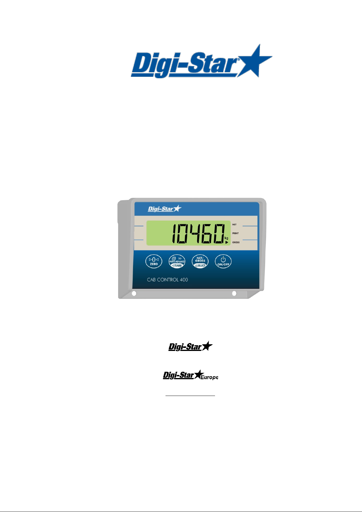
CC400
User Manual
Ft. Atkinson, Wisconsin USA
Panningen, the Netherlands
www.digi-star.com
D3674-GB Rev C June 28, 2011
Page 2

Cab Control 400
Page 3

Operators Manual
3
Contents
Getting Started ................................................................................................................ 1
Installing Cab Control 400 ............................................................................................... 1
Operating the Cab Control 400........................................................................................ 2
Setting-Up the Indicator................................................................................................... 3
Setting-Up the Cab Control 400 ...................................................................................... 4
Running Self Test............................................................................................................ 5
Low Battery Indication ..................................................................................................... 5
FCC Notifications ............................................................................................................ 5
D3674-GB Rev C
Page 4

Page 5

Operators Manual
1
Wire Color
Wire Function
RED
Battery (+12VDC)
BLACK
GROUND
Getting Started
The Cab Control 400 allows the loader operator to communicate via radio signal to a
properly equipped EZ indicator. Once in contact with an indicator, the Cab Control allows
the loader operator to view the indicator display and control the indicator by pressing buttons
on the Cab Control front panel.
Installing Cab Control 400
Mounting Location
Metal structures surrounding the indicator and the Cab Control 400 may block the radio
signal. The Cab Control 400 is designed to work with the EZ indicator mounted inside the
cab of a truck or tractor and the Cab Control 400 mounted in a loader or tractor cab at
dashboard level or above.
Connecting Power
Power can be obtained directly from either a 12 Volt or a 24 Volt electrical system or for
stationary applications, from a 120VAC to 12VDC power cube that plugs into a wall outlet.
Warning! Disconnect the Cab Control 400 power cord before jump-starting
or fast-charging the battery.
Connect the RED wire from the power cable to 12VDC or 24VDC and the BLACK wire to
GROUND. The Cab Control 400 is fused internally at 2 Amps but typically uses less than
0.20 Amps. The Orange and Blue wires are not connected.
D3674-GB Rev C
Page 6

Cab Control 400
2
Zero
Print and Tare
On/Off
Net/Gross and Select
Operating the Cab Control 400
Cab Control 400 Keys
Three of the four Cab Control 400 keys have dual function. The function listed on the top of
the key is actuated by momentarily pressing the button. The function listed on the bottom of
the key requires the operator to “press and hold” the key.
Zero .................... Pre s s mo mentarily.
Print .................... Press mo mentarily .
Tare .................... Press for 1-1/2 seconds.
Net/Grs ............... Press momentarily.
Select .................. Press for 1-1/2 seconds.
On ....................... Press momentarily.
Off ....................... Press for 3 seconds.
NOTE: Use the “Print” key on the Cab Control 400 to advance ingredient when in the
batching mode.
Turn on the Cab Control 400
Press [On].
- A brief hello and Cab Control message will be displayed.
- If no signal is being received, the indicator will flash NODATA and the scale number.
- If a signal is being received, the Cab Control 400 display will match the display on the
- Pressing a key on the Cab Control 400 front panel causes that key-press to be
NOTE: To turn Cab Control 400 off, press and hold [On/Off] until “
Example: SCL 2.
scale.
entered on the scale indicator.
indicator cannot be turned on or off from the Cab Control 400.
BYE
” is displayed. Scale
Page 7

Operators Manual
3
Communicate with a Different Truck
1. Press and hold [Net/Grs] 1-1/2 seconds to enter the “select” mode. The Cab
Control 400 will display the indicator number that is currently communicating.
2. Press [Select] again (within 3 seconds) until desired indicator number is
displayed.
NOTE: After 3 seconds, the Cab Control 400 displays the currently selected scale.
- If a signal is being received, the Cab Control 400 display will match the display on the
scale.
- If the desired scale number is not being displayed, see “Set Up the Cab Control
400” steps 1 through 7 on page 4.
Setting-Up the Indicator
The EZ indicator has a factory-installed and configured radio that is assigned a unique scale
number (SCL NO). Two indicators cannot operate using the same scale number. The
following setup parameters are required for proper radio operation:
Remote - on
Scl no - (Select 1 – 12)
NOTE: For best performance on systems with six or less indicators, use scales
numbered 1 - 6.
Change Scale Number on Indicator Using Long Form Setup
1. Enter the Long Form Setup by holding [Net/Grs] and [On] for three seconds.
2. Press [Net/Grs] or [Select] to advance to Menu 2.
3. Press [On] to advance to REMOTE.
4. Press [Net/Grs] or [Select] to set to ON.
5. Press [On] to save setting and advance to SCL N0.
6. Press [Net/Grs] or [Select] to set to desired scale.
7. Press [On] to save setting and advance to end of menu.
D3674-GB Rev C
Page 8

Cab Control 400
4
Setting-Up the Cab Control 400
The Cab Control 400 is setup at the factory. There is one selection for the buzzer, one for
AUTOFF and twelve selections to enable or disable communications from each of the twelve
available scales. If necessary to re-configure the setup parameters, see below.
Buzzer - T ur n audio alarm OFF or ON.
AUTOFF - Set Cab Control 400 to turn off after 15, 30 or 60 minutes.
SCL NO - Disable or enable each of the twelve scale selections.
Note: Disabling unused scale selections allows the operator to avoid selecting scales
that are not in use.
Setup Cab Control 400
1. Follow steps “a” and “b” to enter the “SETUP” menu:
a. Turn the unit off.
b. Press [On] while holding either [Net/Grs] or [Select] for 8 seconds.
setup and Buzzer will show on the display followed by the current setting.
2. Press [Net/Grs] or [Select] to toggle the buzzer on or off.
3. Press [On] to save the setting and advance to AUTOFF.
4. Press [Net/Grs] or [Select] to select OFF, 15, 30 or 60.
5. Press [On] to save the setting and advance to the next selection.
6. Press [Net/Grs] or [Select] to enable (Y) or disable (N) each of the twelve available
scales.
7. Press [On] to save the setting and advance to the next selection.
8. After scale number twelve has been set, press [On] to exit or [Net/Grs] to run self-
test.
Example below illustrates how to set up a system with two scales. Buzzer is set to on,
Autoff is set to 60 minutes and Scale #1 and Scale #2 are enabled:
buzzer - on
autoff - 60
scllst
sco1-y sco5-n sc09-n
Sco2-y sco6-n sc10-n
sco3-n sc07-n sc11-n
sco4-n sc08-n sc12-n
NOTE: On systems with six or less scales, use scales numbered 1 through 6.
Page 9

Operators Manual
5
Running Self Test
To run the self-test on the Cab Control 400, follow instructions under “Setup Cab Control
400” steps 1 through 7 on page 4 and press [Net/Grs] in step 8.
Low Battery Indication
If the power supply voltage drops below the (10.5 Volts), the message RECHARGE BATTERY TURNING OFF” and L0 PWR will periodically show on the display to alert the operator of the low
battery condition.
LO BAT
NOTE: If
Warning! Disconnect the Cab Control 400 power cord before jump-
is displayed, the indicator power (not the Cab Control 400 power) is below
10.5 volts.
starting or fast-charging the battery.
FCC Notifications
FCCID: OUR-24XTREAM
This device complies with part 15 of the FCC rules. Operation Is subject to the following
conditions:
(1) This device may not cause harmful interference and (2) this device must accept any
interference received, including interference that may cause undesirable operation.
To comply with FCC regulations, this device may be used only with approved antennas.
Contact Digi-Star Customer Support for additional information.
Warning! This equipment is approved only for mobile and base station
transmitting devices, separation distances of 20 centimeters (8
inches) or more should be maintained between the antenna and
nearby persons during operation. To ensure compliance, operation
at distances closer than this is not recommended.
D3674-GB Rev C
 Loading...