

Page 1

Case IH
1250 - 12/16/24 Row
Planter Scale
Instructions
And
Repair Parts
Ft. Atkinson, Wisconsin USA
Panningen, The Netherlands
www.digi-star.com
D3870-US Rev B August 26, 2011
Page 2
Table Of Contents
TABLE OF CO NTENTS
INTRODUCTION ...................................................................................................................................................................................... 1
Charging Battery and Welding ............................................................................................................................................................... 1
SCALE KIT MOUNTING INSTALLATION – 12, 16 ROW............................................................................................................................ 2
Front Load Cell ..................................................................................................................................................................................... 3
Right Side View .................................................................................................................................................................................... 4
Rear Load Cell ...................................................................................................................................................................................... 5
Rear Scale Mount Components ............................................................................................................................................................. 6
Junction Box ......................................................................................................................................................................................... 6
SCALE KIT MOUNTING INSTALLATION - 24 ROW .................................................................................................................................. 7
Right/Left Load Cell Bracket .................................................................................................................................................................. 7
Front Bracket ........................................................................................................................................................................................ 8
Rear Load Cell and Bracket .................................................................................................................................................................. 9
JUNCTION BOX MOUNTING ................................................................................................................................................................. 10
Connect Load Cell and J-Box Cable .................................................................................................................................................... 10
Installing wires into Terminal Block ...................................................................................................................................................... 10
INDICATOR MOUNTING ........................................................................................................................................................................ 11
Power Connection:.............................................................................................................................................................................. 11
Load Cell Connection: ......................................................................................................................................................................... 11
TROUBLE SHOOTING ........................................................................................................................................................................... 12
How to Check the Drill Scale after Installation ...................................................................................................................................... 12
REPAIR PARTS ..................................................................................................................................................................................... 13
406429 Kit – Scale CNH1250, 12, 16 Row ........................................................................................................................................... 13
406467 Kit – Scale CNH1250, 12, 16 Row, Indicator in Tractor Cab ..................................................................................................... 13
406306 Kit – Scale CNH1250, 24 Row ................................................................................................................................................ 14
406307 Kit – Scale CNH1250, 24 Row, Indicator in Tractor Cab ........................................................................................................... 14
INDICATOR SWIVEL MOUNT ................................................................................................................................................................ 15
LICENSE AGREEMENT ......................................................................................................................................................................... 16
All rights reserved. Reproduction of any part of this manual in any form whatsoever without Digi-Star’s express written permission is forbidden. The contents of this manual are subject
to change without notice. All efforts have been made to assure the accuracy of the contents of this manual. However, should any errors be detected, Digi-Star would greatly appreciate
being informed of them. The above notwithstanding, Digi-Star can assume no responsibility for errors in this manual or their consequence.
© Copyright! 2008 Digi-Star, Fort Atkinson (U.S.A.).
Case IH Planter Scale D3870-US Rev B
Page 3
Introduction
p
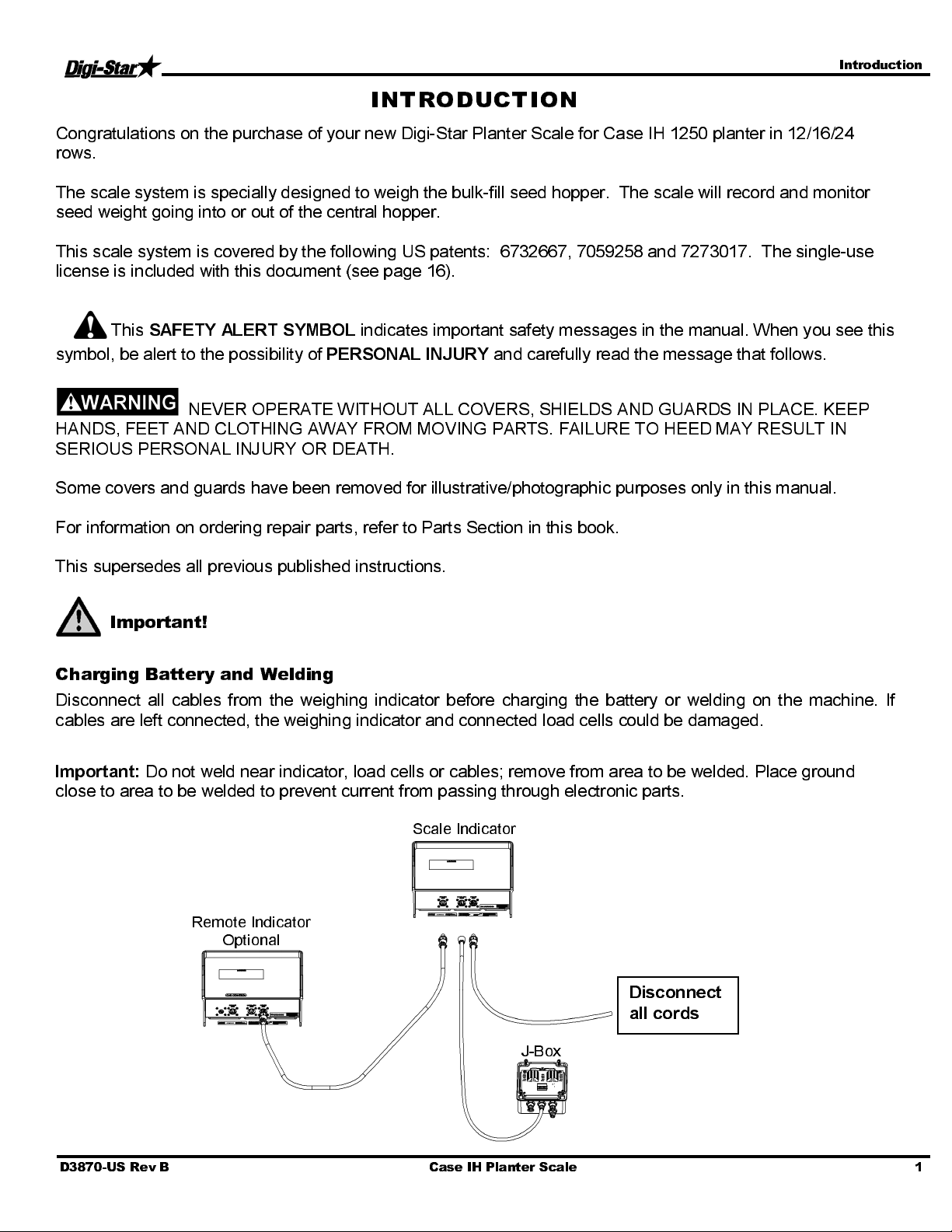
INTRODUCTION
Congratulations on the purchase of your new Digi-Star Planter Scale for Case IH 1250 planter in 12/16/24
rows.
The scale system is specially designed to weigh the bulk-fill seed hopper. The scale will record and monitor
seed weight going into or out of the central hopper.
This scale system is covered by the following US patents: 6732667, 7059258 and 7273017. The single-use
license is included with this document (see page 16).
This
SAFETY ALERT SYMBOL
symbol, be alert to the possibility of
NEVER OPERATE WITHOUT ALL COVERS, SHIELDS AND GUARDS IN PLACE. KEEP
HANDS, FEET AND CLOTHING AWAY FROM MOVING PARTS. FAILURE TO HEED MAY RESULT IN
SERIOUS PERSONAL INJURY OR DEATH.
Some covers and guards have been removed for illustrative/photographic purposes only in this manual.
For information on ordering repair parts, refer to Parts Section in this book.
This supersedes all previous published instructions.
indicates important safety messages in the manual. When you see this
PERSONAL INJURY
and carefully read the message that follows.
Important!
Charging Battery and Welding
Disconnect all cables from the weighing indicator before charging the battery or welding on the machine. If
cables are left connected, the weighing indicator and connected load cells could be damaged.
Important:
Do not weld near indicator, load cells or cables; remove from area to be welded. Place ground
close to area to be welded to prevent current from passing through electronic parts.
Scale Indicator
Remote Indicator
tional
O
Disconnect
all cords
J-Box
D3870-US Rev B Case IH Planter Scale 1
Page 4
Scale Kit Mounting Installation – 12, 16 Row
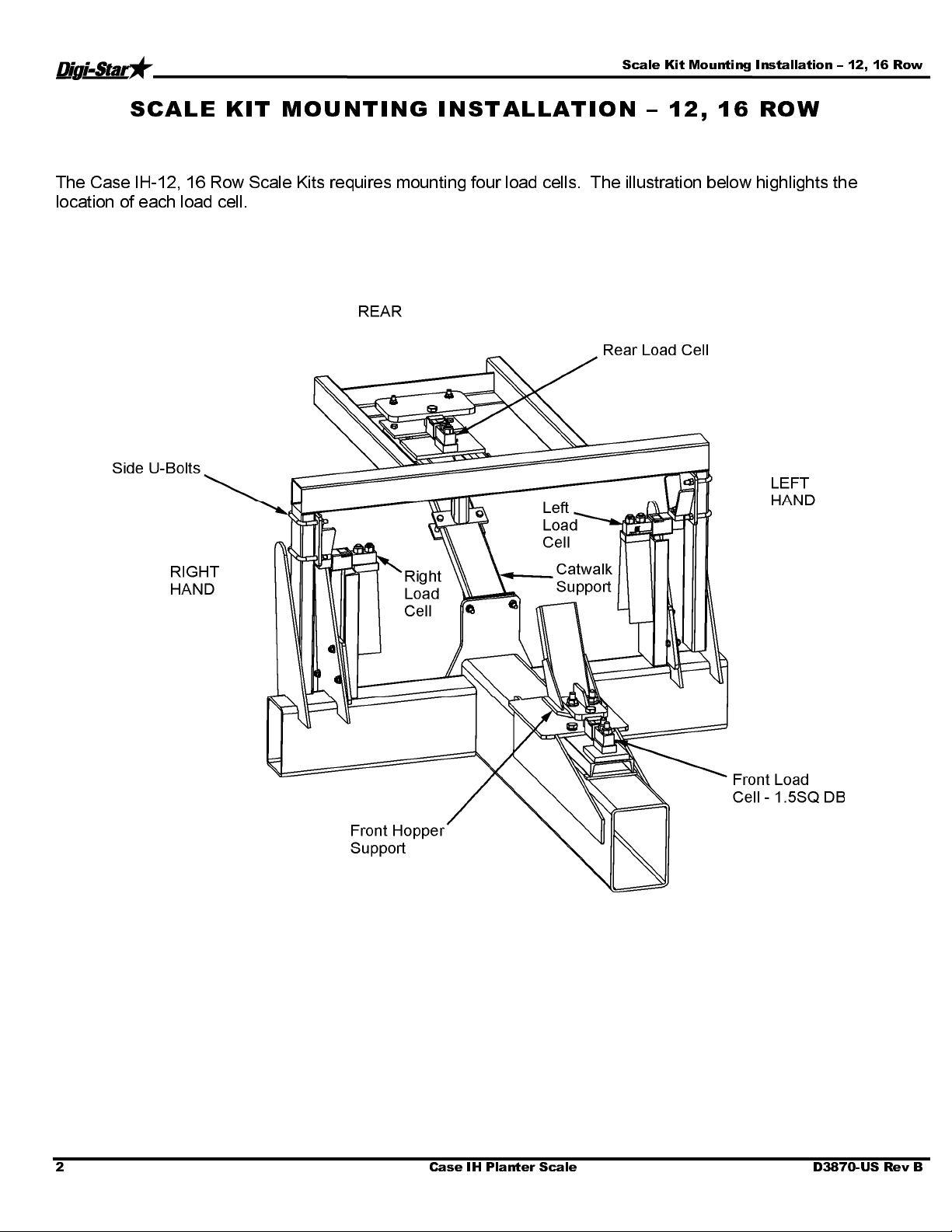
SCALE KIT MOUNTI NG INSTALLA TION – 12 , 16 ROW
The Case IH-12, 16 Row Scale Kits requires mounting four load cells. The illustration below highlights the
location of eac h loa d cell.
2 Case IH Planter Scale D3870-US Rev B
Page 5
Scale Kit Mounting Installation – 12, 16 Row
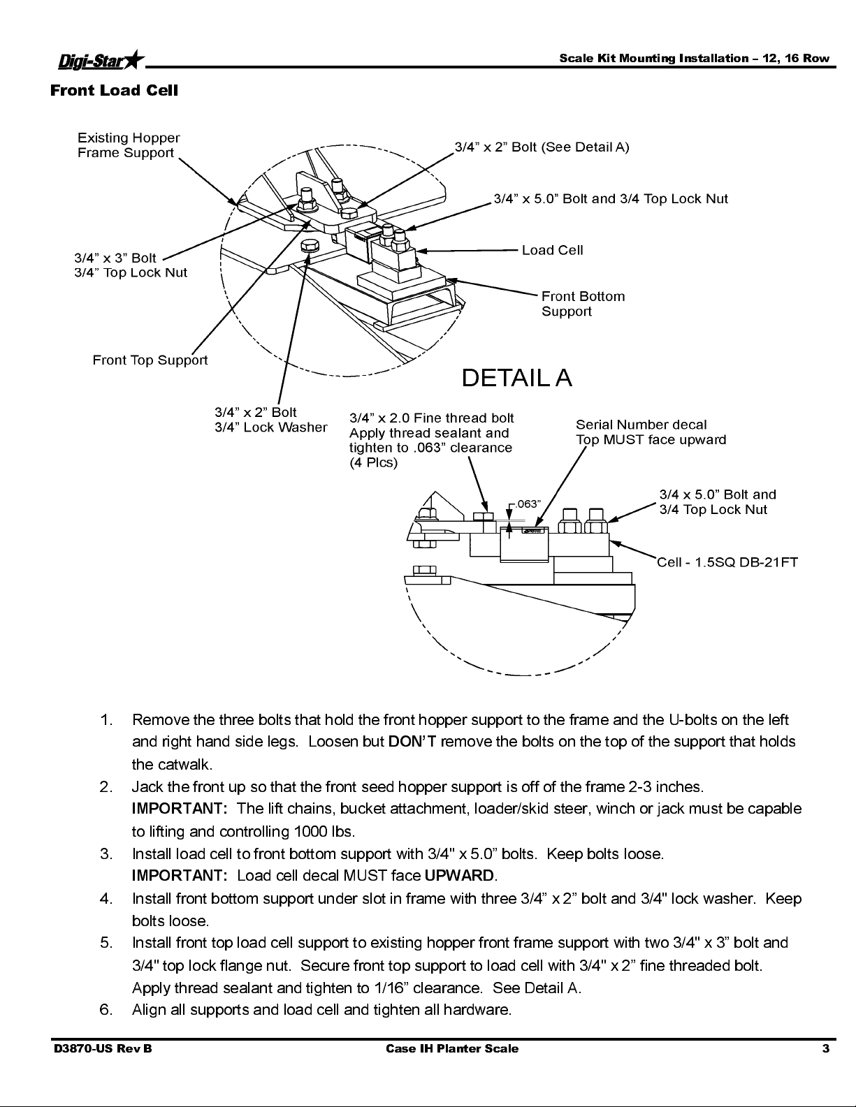
Front Load Cell
1. Remove the three bolts th at hol d the fro nt ho pp er sup port to th e fr ame and the U-bolts on the left
and right hand side legs. Loosen but
DON’T
remove the bolts on the top of the support that holds
the catwalk.
2. Jack the front up so th at the fro nt see d ho pp er supp ort is of f o f th e fram e 2-3 inch es.
IMPORTANT:
The lift chains, bucket attachment, loader/skid steer, winch or jack must be capable
to lifting and controlling 1000 lbs.
3. Install load cell to front bottom support with 3/4" x 5.0” bolts. Keep bolts loose.
IMPORTANT:
Load cell decal MUST face
UPWARD
.
4. Install front bottom support under slot in frame with three 3/4” x 2” bolt and 3/4" lock washer. Keep
bolts loose.
5. Install front top load cell support to existing hopper front frame support with two 3/4" x 3” bolt and
3/4" top lock flange nut. Secure front top support to load cell with 3/4" x 2” fine threaded bolt.
Apply thread sealant and tighten to 1/16” clearance. See Detail A.
6. Align all supports and load cell and tighten all hardware.
D3870-US Rev B Case IH Planter Scale 3
Page 6
Scale Kit Mounting Installation – 12, 16 Row
Right Side View
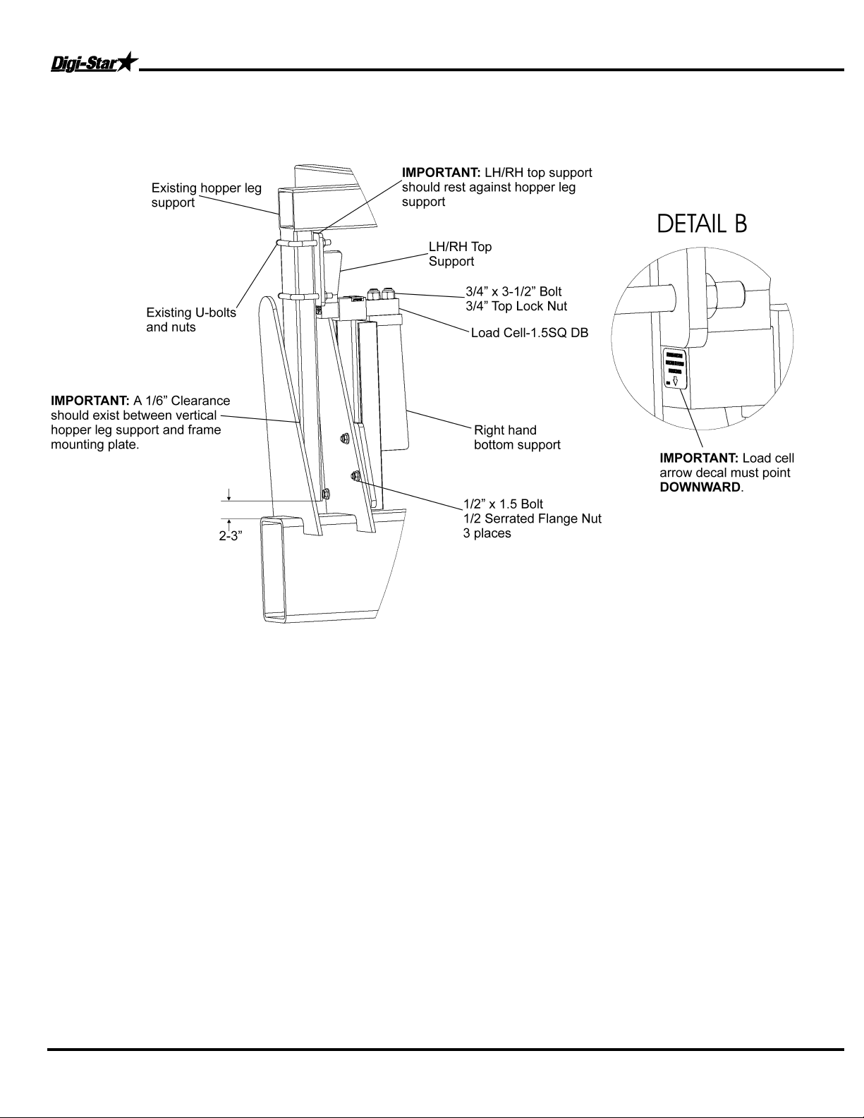
7. Raise hopper leg support 2-3” and mount right hand top support to hopper leg support with two
existing U-bolts and nuts.
Note: Top support should rest against hopper leg support.
8. Mount right hand bottom support to inner planter frame plate with 1/2" x 1.5 bolt and 1/2" serrated
flange nut.
9. Mount load cell to right hand bottom support with 3/4" x 3-1/2” bolt and 3/4" top lock nut.
IMPORTANT: Make sure the arrow on the end of the load cell is pointed down. Mount short
load cell end (side with single mounting hole) to top support with 3/4" x 2.0 fine thread bolt. Apply
thread sealant and tighten to 1/16” clearance. See Detail A on page 3.
10. Align all supports and load cell and tighten all hardware.
11. Repeat for left hand side.
4
Case IH Planter Scale D3870-US Rev B
Page 7

Scale Kit Mounting Installation – 12, 16 Row
Rear Load Cell
12. Remove two bolts that hold the existing catwalk support to catwalk frame. Raise catwalk two
inches.
13. Mount load cell mounting plate to top side of catwalk angle iron frame with 1/2" x 2-1/4” bolt and
1/2" serrated flange nut. Tighten hardware. See Detail C on page 6.
14. Mount rear top bracket to existing catwalk brace with 1/2" x 3-1/2” bolt and 1/2" serrated flange nut.
Leave hardware loose.
15. Mount extra rear center brace to bottom existing catwalk brace with 1/2" x 3.0 bolt and 1/2"
serrated flange nut.
16. Mount Load Cell-1.5SQ DB to rear top bracket with 3/4" x 3.0 bolt and 3/4" top lock nut.
MPORTANT: Make sure the arrow on the end of the load cell is pointed down. Mount short
load cell end (side with single mounting hole) to load cell mounting plate with 3/4" x 2.0 fine
threaded bolt. Apply thread sealant and tighten to 1/16” clearance. See Detail A on page 3.
17. Align all supports and load cell and tighten all hardware.
D3870-US Rev B Case IH Planter Scale
5
Page 8

Scale Kit Mounting Installation – 12, 16 Row
Rear Scale Mount Components
Junction Box
•
Clean the area thoroughly and let dry.
•
Peel the ad hesiv e tap e o f f an d press on .
Press firmly for at least 30 secon ds.
•
Run the wires from the weigh bars in a safe
spot where they cannot get pinched or
rubbed. If possible run the wires along with
other wires or hoses on the planter.
•
Mount the indicator on the rear catwalk
tubing where it is most convenient. Make
sure wires are protected from bei ng
pinched or rubbed.
6 Case IH Planter Scale D3870-US Rev B
Page 9

Scale Kit Mounting Installation - 24 Row
SCALE KIT MOUNTI NG INSTALLA TION - 24 ROW
The Case-IH-24-Row Scale Kits requires mounting four load cells. The illustration below highlights the location
of each load cells.
1. Remove the one U-bolt on
the bracket which sits
between the steps and the
main planter frame on the
rear of the planter.
2. Loosen the U-bolts on the
front leg bracket located
between the front of the
hopper and the main frame.
3. Loosen the bolt on the two
left brackets th at are locat ed
under the catwalk.
4. Remove the bolts on the two
right leg brackets.
5. Lift up the two right legs
about 1-1/2”.
IMPORTANT:
chains, bucket att achm en ts,
loader/skid steer, winch or
jack must be capable of
lifting and contr olling 1 00 0
lbs.
The lift
Right/Left Load Cell Bracket
D3870-US Rev B Case IH Planter Scale 7
Page 10
Scale Kit Mounting Installation - 24 Row
6. Mount RH bottom bracket with supplied U-bolts 5/8” x 7-3/4” and 5/8” top lock flange. Insert part
number 400525 Cell-2-1/8” DW with 11 foot cable into bottom bracket and secure with 3/4” x 3-1/2” bolt
and 3/4” lock nut. The short end of load cell is installed in the bottom bracket; the long end is installed
in the top bracket. IMPORTANT: Load cell
arrow decal must point UP.
7. Bolt the top load cell bracket and support
bracket together. With 5/8” x 7.0 bolt and 5/8”
top lock flange nut. The two existing planter
frame legs are bolted between the top bracket
and 4 x 2 x 34” tubing. The top bracket needs
to be adjacent to the frame under the catwalk.
8. Repeat the same procedure for the left side
load cell.
Front Bracket
8
Case IH Planter Scale D3870-US Rev B
Page 11

Scale Kit Mounting Installation - 24 Row
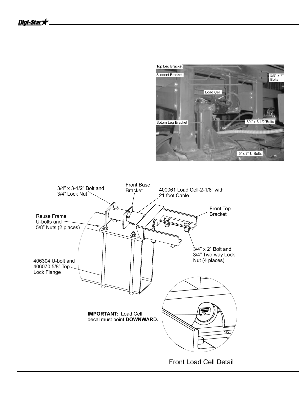
9. Remove the U-bolt on the front bracket and lift up the hopper 1-1/2”.
10. Bolt front top bracket to existing front hopper leg using 3/4" x 2” bolt and 3/4" two-way lock nut.
11. Install load cell (part number 400061) to the front base bracket using 3/4" x 3-1/2” bolt and 3/4" lock nut.
Make sure arrow load cell decal is pointing
downward (
See Front Load Cell Detail). Install the short
load cell end to the front top bracket using 3/4" x 3-1/2” bolt and 3/4" lock nut. Reuse frame U-bolts and
5/8” nuts.
Rear Load Cell and Bracket
12. Install rear brackets in the same manner as the front brackets. Use one existing 5/8” U-bolt, plus one
new 5/8” x 8.75 U-bolt and 5/8” top lock flange nut to bolt the rear base bracket to planter main frame.
Install rear top step bracket with 3/4" x 2.0 bolt and 3/4" two way lock nut. Install 400061Load Cell-2-
1/8” DB with 3/4" x 3-1/2” bolt and 3/4" lock nut. Make sure load cell decal must point
downward
.
D3870-US Rev B Case IH Planter Scale 9
Page 12

Junction Box Mounting
JUNCTION BOX MOUNTING
The junction box is water resistant, not water-proof. It should be mounted to avoid submersion during wet
weather and to avoid physical abuse. The junction box can be mounted on the front or rear of the drill,
planter or seeder. All load cell cables must reach the J-Box. Install by removing the double sided tape
backing and apply to cleaned surface.
Connect Load Cell and J-Box Cable
1. Route front and rear load cell cables to J-box location.
Make sure they are not bound or pinched. Cable tie
(customer provided) load cell cables in place.
2. Insert load cell and J-box cables through each of the
water-tight strain-reliefs.
3. Remove each terminal block from the J-box.
4. Connect wires of the same color to the same terminal
block. See instructions below.
5. Install terminal block into the J-box as shown (location
not important).
6. Tighten nuts on the water-tig ht strain-relie f s.
7. Assure that gasket is properly installed in the cover.
8. Attach cover using 4 screws (provided).
Installing wires into Terminal Block
1. Open levers 90º to locked position.
2. Insert individual wires into terminal.
3. Close lever.
4. Tug wire to assure solid connection.
Note: Wire strip length is 7/16” (11mm).
406232 J-Box Lever Nut 4Pt (Planter)
141837 Cable - 30Ft J-Box
406074 Cable - 45Ft J-Box
403335 Cable - Power 17Ft 2-Wire
406073 Cable - Power 36Ft 2-Wire
406072 Cable - Power 6Ft 2-Wire
824316 Cable - 15Ft-J-Box
145096 Cable - 70Ft-J-Box
406276 Cable – Power 65Ft 2-Wire
10 Case IH Planter Scale D3870-US Rev B
Page 13

Indicator Mounting
r
W
D
INDICATO R MOUNTI NG
The scale indicator can be mounted in the tractor cab or on the planter with swivel mounting pack (406629).
Depending on which kit you purchase, two cables must be connected to the indicator bottom panel, J-Box and
power cables. Refer to Indicator Manual D3831-US for details of indicator mounting options and connection of
power cord.
1. Bolt the readout in the cab, or mount the swivel bracket on the drill, planter or seeder.
2. Install power cord to a 12-volt negative ground battery.
3. Route J-box cable to indicator and install to indicator bottom panel.
4. Program indicator with set-up #125040 and calibration #32000 (see Indicator Manual) for Case IH 24
Row; set-up #145016 and calibration #15000 for Case IH 12/16 Row.
INDICATOR MOUNTINGS
TRACTOR CAB MOUNTING U-BOLT RAM MOUNT
Power Connection:
The power cable should be connected directly to a vehicle battery or regulated power supply. The scale end of
the power cable is attached to the J901 connector located on the bottom panel of the indicator.
Connect the RED wire from the power cable to +12 VDC and the BLACK wire to GROUND. The indicator is
fused inter nally at 4 amps.
Power Cable Connections:
Wire colo
Red
Black
ire Function
Battery (+12 VDC)
GROUN
Load Cell Connection:
The indicator is designed to operate with strain gage load cells. The indicator will normally be supplied with a
“J-BOX” cable going between the scale and the load cell junction box. Extension kits
are available from your
dealer in various lengths.
Load Cell Wire Digi-Star Function
1 RED +EX
2 GREEN -SIG
3 WHITE +SIG
4 BLACK -EX
5 CLEAR SHIELD
D3870-US Rev B Case IH Planter Scale 11
Page 14
Trouble Shooting
TROUBLE SHOOTI NG
How to Check the Drill Scale after Installation
For the first test, lift the drill, planter or seeder all the way up, to a level area. Put 200-250 pounds of weight on
the right side, then compare it to the left. Both sides should be within four to six pounds of each other.
•
If the weight is not within the four to six pound range, inspect the scale system for loose or misalign
mounts.
The second test is to lift the drill, planter or seeder to a level area and zero the scale. Lift the
drill/planter/seeder up and down two to three times, checking to see if the scale zeros out. Each time the scale
is in the up position, it should be within four to six pounds.
If further assistance is necessary, please call Digi-Star, LLC at 920-563-9700.
***The example we are using is 2000 lbs of seed evenly filled in both hoppers. There is 25 lbs of seed left from
the last fill.
Push the “Start” button. The screen will show zero, and the arrow is now pointing to “Net” on the screen. This
is a temporary zero point to start loading the planter with seed. You will now fill 1000 lbs of seed into the left
hopper.
Push the “Stop” button, the readout now reads 1025 lbs of seed inventory.
Push the “Start” button again. The screen will say zero again. Load another 1000 lbs of seed into the right
side.
Now push “Stop” and the screen will read 2025 lbs of seed. The number will decrease as the seed is planted.
12 Case IH Planter Scale D3870-US Rev B
Page 15

Repair Parts
REPAIR PARTS
406429 Kit – Scale CNH1250, 12, 16 Row
406467 Kit – Scale CNH1250, 12, 16 Row, Indicator in Tractor Cab
KEY QTY.
1 1 406417 Weld – R e a r C e n t e r B r a ce ( CNH1250) 12 4 406067 S c r – 3 / 4 -16 x 2. 0 HHCS Grd 5 ZP
2 1 406421 We l d – Rear Top Br ac ke t (CNH 1250 ) 13 4 406458 Scr – 1 / 2 - 1 3 x 3 . 5 HHCS Grd 5 ZP
3 1 406430 Plate – LC Mount 3/4" 14 4 405854 Scr – 1/2 -13 x 2-1/4 HHCS Grd 5 ZP
4 2 406434 W e l d – L H / R H T op S u p po r t ( C N H1 2 5 0) 15 6 406459 Scr – 1/ 2 -13 x 1.5 HHCS Grd 5 ZP
5 1 406448 Weld – LH Side Support (CNH1250) 16 8 405921 Nut – 3/4-10 Top Lock ZP
6 1 406449 Weld – RH Side Support (CNH1250) 17 4 405988 Nut – 3/4-10 Top-Lock Flange ZP
7 1 406431 Weld – F r o n t T o p S upport (CNH1250) 18 14 406085 Nut – 1/2-13 Ser Flange ZP
8 1 406438 W e l d – F r o n t B ottom S upport (CNH1250) 19 3 405273 Washer – 3/4 Split Lock ZP
9 6 406068 Scr – 3/4-10 x 3.5 HHCS Grd 8 ZP 20 4 404284 Cell – 1.5 Sq. DB-21 Ft
10 2 405272 Scr – 3/4-10 x 3.0 HHCS Grd 5 ZP 21 2 405937 Scr – 3/4 x 5.0 HHCS ZP Grd 5
11 5 406301 Scr – 3/4-10 x 2.0 HHCS Grd 5 ZP
PART
NO.
DESCRIPTION KEY QTY.
PART
NO.
DESCRIPTION
D3870-US Rev B Case IH Planter Scale 13
Page 16

Repair Parts
406306 Kit – Scale CNH1250, 24 Row
406307 Kit – Scale CNH1250, 24 Row, Indicator in Tractor Cab
KEY QTY.
1 2 406295 W e l d – R ea r B a se B r a c ke t ( C N H 12 5 0 ) 10 4 406305 U-Bolt 5/8-11 x 7.75W x 4.5L
2 1 406288 W e l d – R e a r T op B r a c k e t (C N H 12 5 0 ) 11 8 406068 Scr 3/4-10 x 3.5 HHCS Grd 8 ZP
3 1 406289 W e l d – F r o n t T o p B r a c k e t (CN H 1250) 12 6 406301 Scr 3/4- 10 x 2. 0 HHC S Gr d 5 ZP
4 1 406278 W e l d – R H Bo t t o m B r a c ke t ( C N H 12 5 0 ) 13 8 406302 Scr 5/8-11 x 7.0 HHCS Grd 5 ZP
5 1 406277 W e l d – L H Bo t t o m B r a c ke t ( C N H 12 5 0 ) 14 14 406303 Nut 3/4-10 2-Wa y Lock ZP
6 1 406283 We l d – R H T o p B r a c k e t ( CNH 1250) 15 18 406070 Nut 5/8-11 Top-Lock Flange ZP
7 1 406284 We l d – L H T o p B r a c k e t ( CNH 1250) 16 2 400525 Cell - 2.125 DB
8 2 406335 Tube – Rect Support 34” Red 17 2 400061 Cell – 2-1/8 DB Pin H - 4140
9 1 406304 U-Bolt 5/8-11 x 8.75W x 17.5L Grd
14 Case IH Planter Scale D3870-US Rev B
PART
NO.
DESCRIPTION KEY QTY.
5 ZP
PART
NO.
DESCRIPTION
Grd 5 Zp
Page 17

Indicator Swivel Mount
INDICATO R SWIVEL M OUNT
406629
KEY QTY. PART NO. DESCRIPTION
1 1 403180 Assembly – 1” Ram Mount
2 1 403179 Mount Base – 1” Ball U-Bolt
3 4 403779 SCR #10 x 5/8” PHSTS 48-2 Blk ZP
406385
KEY QTY. PART NO. DESCRIPTION
1 1 404230 Ram Suction Cup with Twist Lock
2 1 403180 Assembly – 1” Ram Mount
3 4 403779 Scr - #10 x 5/8 PHSTS 48-2 Blk ZP
406385 – 1” Ram Mount with Suction Cup 406629 – 1” Ram Mount with U-Bolt Mount
D3870-US Rev B Case IH Planter Scale 15
Page 18

License Agreement
LICENSE AGREEMENT
IMPORTANT NOTICE: Acceptance and use of the enclosed electronic scale products (hereinafter referred to as
“Purchased Product”) constitutes your agreement to the following terms and conditions. Please carefully read the
following terms and conditions before using or reselling the Purchased Product.
1. Limited License
(“Owner”) is the owne r of the fo llowing U.S. Patents r elated to grain
drills: 6,732,667, 7,059,258, 7,273,017, 7,357,087, 7,448,335,
7,523,710 and any other patents which result from continuation
applicatio ns there of (“Patents”). Owner he reby grants t o the custom er
(“Customer”) a non-exclusive, non-transferable, revocable, limited
license to use the technology described in the Patents to use the
Purchased P roduct to assembl e a seed planter p roduct cov ered b y th e
Patents (“L i c ense d Pr o du ct”) , and t o s ell an d o f f e r f o r sal e on e (1) un i t
of the Licensed Product in accordance with the terms and conditions set
forth herein. Alternatively, Customer may resell the Purchased Product
to another entity for the purpose of that entity assembling one (1) unit of
a Lic ensed Product under a permit ted sublicense from the Customer
with the same terms as this Agreement. If Customer would like to
assemble, use, sell or offer for sale more than one (1) Licensed Product,
or resell m ore than one (1) Purchas ed Product, Custom er understands
and agrees that it must purchase another Purchased Product from Owner
or acqui r e a sepa rat e l ic e nse b y r equ esti ng and pu r chasing an o th er un i t
of the same SKU number that resulted in this purchase.
2. Acceptance of Terms and Conditions
authority to enter int o this binding agreement. If Custom er does not
accept th e te rms and cond itio ns, Custome r shall not us e the Pur chase d
Product . Cust om er und ers tands and ag re es that i f it us es th e Pur chas e d
Product as p ermitte d herein , it will be d eemed t o have a ccept ed these
terms and conditions and they shall become a binding agreement.
3. Limitations on Use
Product only as e xpressly au thorize d in this Agreemen t, and that any
use not e xpr essl y auth o ri z ed in t his Agr e em ent is pr oh ibi te d. Cust om e r
agrees that it will n o t: (i ) l oan, r en t, l ease , assign, subli c ense , distr ibut e
or ot herwise trans fer its rights under th is Agreemen t to a third party ,
other than to resell the Purchased Product to another entity for the
purpose o f that entit y assembling one un it of a Li censed Produ ct; (ii)
copy or r eprodu ce the L icens ed Produc t; or (ii i) grant any subl icense s
other tha n to a n en d us er of the Lice nse d Prod uct , or to a nothe r ent ity for
the purpose of that entit y assembling on e unit of a Li censed Pro duct.
Customer agr ees t o use r easonabl e e ff or ts to pr ev ent an y unauth ori ze d
use or copying of the Licensed Product and will notify Owner
immediatel y upon learning o f any such unauthori zed use or copy ing.
Customer’s obl igati o ns und er th is se ct i on shall sur v i v e an y t e rmina ti o n
of th is Agre emen t o r the lic ense g ranted h er eunder . Any unauth ori ze d
use of the Licensed Product will result in, among other things, the
imm ed i a te te r m in a t io n of t h i s l ice n s e.
4.
Ownership of Proprietary Rights
Lic ensed Produc t is cover ed intelle ctual and/or pr oprietary rights, and
that all such inte llectual and propr ietary righ ts are owned by Own er.
Customer hereby acknowledges that it has no rights in the
foregoing except as expressly granted herein.
5. NO WARRANTY
the Purchased Product and Customer acknowledges and agrees
that Owner will not assume any product liability or any other
. Digi-Star, LLC, a Wisconsin limited liability company
. Customer warrants that it has the
. Customer agrees that it will use the Licensed
. Customer acknowledges that the
. Customer agrees to fully test and evaluate
liability for th e Purchased Product or the L icensed Produ ct. Th e
Purchased Product is furnished to Customer “AS IS.”
otherwise provided by separate documentation
MAKES NO WARRANTIES, EITHER EXPRESS OR
IMPLIED, WITH RESPECT TO THE PURCHASED
PRODUCT. Customer agrees that Owner shall have no liability
resulting from Customer’s use of the Purchased Product f or any
indirect damages including consequential, incidental or special
damages for loss of profit, good will or otherwise. Customer
shall indemnify and hold Owner harmless from any and all
losses, expenses, damages, costs or expenses of any kind,
including but not limited to reasonable attorneys’ fees, incurre d
by Owner resulting from Customer’s use of the Purchased
Product. NO ORAL OR WRITTEN STATEMENTS MADE BY
OWNER OR ITS EMPLOYEES INCLUDING BUT NOT
LIMITED TO STATEMENTS REGARDING CAPACITY,
SUITABILITY FOR USE, OR PERFORMANCE OF THE
PURCHASED PRODUCT SHALL BE DEEMED A
WARRANTY OR REPRESENTATION BY OWNER FOR
ANY PURPOSE NOR GIVE RISE TO ANY LIABILITY OR
OBLIGATION OF OWNER.
6. Remedies for Violations
remedies available at law and in equity for violations of this
Agreement, including but not limited to the right to r ecove r the
Licensed Product.
7. Fees
8. Entire Agreement
9. Severability
10. Governing Law
. In consideration for the rights granted under this
Agreement, Customer has paid a license fee that was included in
the amount invoiced to the Customer for the sale of the
Purchased Product.
contrary, this Agreement constitutes the entire agreement
between the parties regarding the subject matter hereof, and no
verbal or written pri or statements or repr esentations of an y sort
made by any party shall be effective or valid for an y purpose
whatsoever. This Agreement may be amended only upon the
mutual consent of all parties in writing.
. If any provision of this Agreement shall be held to
be invalid, illegal or unenforceable, the validity, legality and
enforc eability of the r emaining provisions shall not in any way
be affected or impaired thereby. The failure of any party to
enforc e any pro vision of this Agreement shall not be considere d
a waiver thereof, nor shall such failure prevent the future
enforcement of any such provision.
. This Agreement and the relationship between
the parties shall be governed in all respects by the laws of the
State of Wisconsin and the United States of America. The
parties consent to the jurisdiction and venue of the Wisconsin
and United States courts located in Wisconsin for resolution o f
any dispute under to this Agreement.
.
Owner reserves the right to seek all
. Except as expressly stated herein to the
Except as
, OWNER
Use or sale of the Licensed Product or of Purchased Product shall bind Customer to all terms and
conditions herein without the necessity of signatures on this Agreement.
16 Case IH Planter Scale D3870-US Rev B
 Loading...