

Page 1
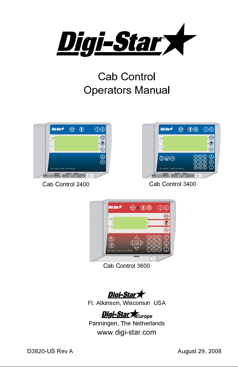
Cab Control
Operators Manual
Cab Control 2400
Cab Control 3600
Cab Control 3400
Ft. Atkinson, Wisconsin USA
Panningen, The Netherlands
www.digi-star.com
D3820-US Rev A August 29, 2008
Page 2
Cab Control
Table Of Contents
BEFORE CHARGING BATTERY OR WELDING......................................3
OPERATION ..............................................................................................4
TURN ON INDICATOR .................................................................... 4
COMMUNICATE WITH DIFFERENT TRUCK ................................. 4
SETTING UP INDICATOR.........................................................................5
SETTING UP THE CAB CONTROL .......................................................... 6
INSTALLATION..........................................................................................7
CAB CONTROL MOUNTING...........................................................7
CAB CONTROL CONNECTION ...................................................... 7
FCC NOTIFICATIONS ............................................................................... 8
2
Page 3
Operators Manual
BEFORE CHARGING BATTERY OR
WELDING
Important Precaution
Disconnect all indicator leads before charging battery or welding.
Damage may occur to indicator.
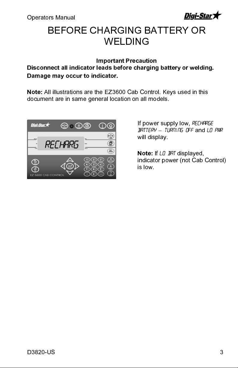
Note:
All illustrations are the EZ3600 Cab Control. Keys used in this
document are in same general location on all models.
Recharg
If power supply low,
battery – turning off
will display.
Note:
If
lo bat
indicator power (not Cab Control)
is low.
recharge
and
displayed,
lo pwr
D3820-US 3
Page 4
Cab Control
See page 7 for installation instructions.
OPERATION
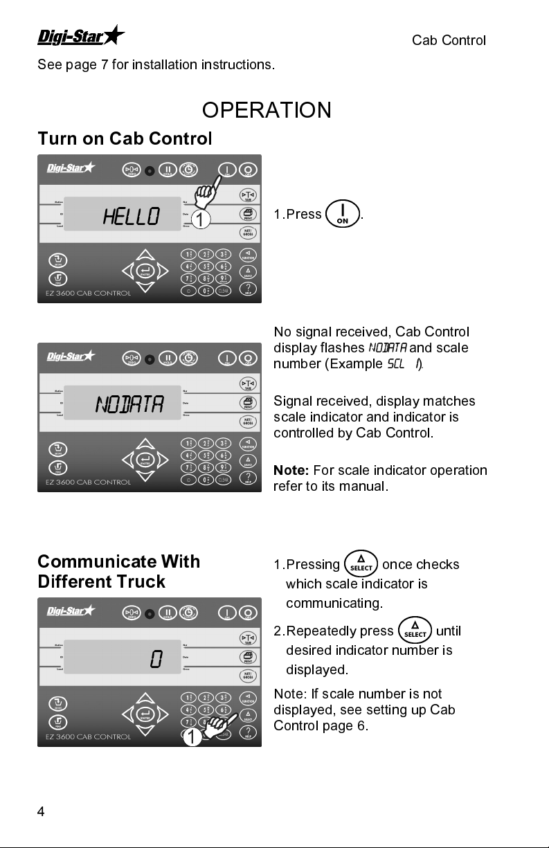
Turn on Cab Control
HELLO
1
Nodata
Communicate With
Different Truck
1. Press .
No signal received, Cab Control
display flashes
number (Example
Signal received, display matches
scale indicator and indicator is
controlled by Cab Control.
Note:
For scale indicator operation
refer to its manual.
1. Pressing once checks
which scale indicator is
communicating.
NODATA
SCL 1).
and scale
2. Repeatedly press until
0
1
4
desired indicator number is
displayed.
Note: If scale number is not
displayed, see setting up Cab
Control page 6.
Page 5

Operators Manual
SETTING UP SCALE INDICATOR
EZ scale indicator has internal radio installed that is assigned a scale
number. Two indicators cannot operate using the same scale number.
To set proper radio operation:
1
1
1. Press and hold a then
press holding both for 3
seconds.
2. Press advances to Menu 2.
2
4
3
4
3
5
6
5
3. Press advances to
Press sets to on.
4. Press saves setting and
advance to
sets desired scale number.
5. Press and hold and
press to return to scale
operation.
6. Press .
Note:
For best performance with six
or less indicators, use numbers 1-6.
scl no
. Press
remote
.
D3820-US 5
Page 6

Cab Control
SETTING UP THE CAB CONTROL
setup
7
6
5
6
1
2
2
4
5
4
1. Press .
2. Press and hold then
press holding both for 10
seconds.
3.
SETUP
and
BUZZER
will show on
display followed by current
setting.
4. Press toggles buzzer on/off
then press to advance to
autoff
.
5. Press set to off, 15, 30 or
60 seconds. Press .
6. Press to enable or disable
each of twelve available scales.
Press .
7. After last scale set press to
exit.
6
Page 7
Operators Manual
INSTALLATION
Cab Control Mounting
The Cab Control communicates with a scale indicator using an internal
radio. For best results, place both indicator and Cab Control in locations
not surrounded by metal. Glass does not block radio signals.
NOTE: The Cab Control usually works fine if the scale indicator is
mounted inside the truck cab and the Cab Control is mounted inside the
loader at dashboard level.
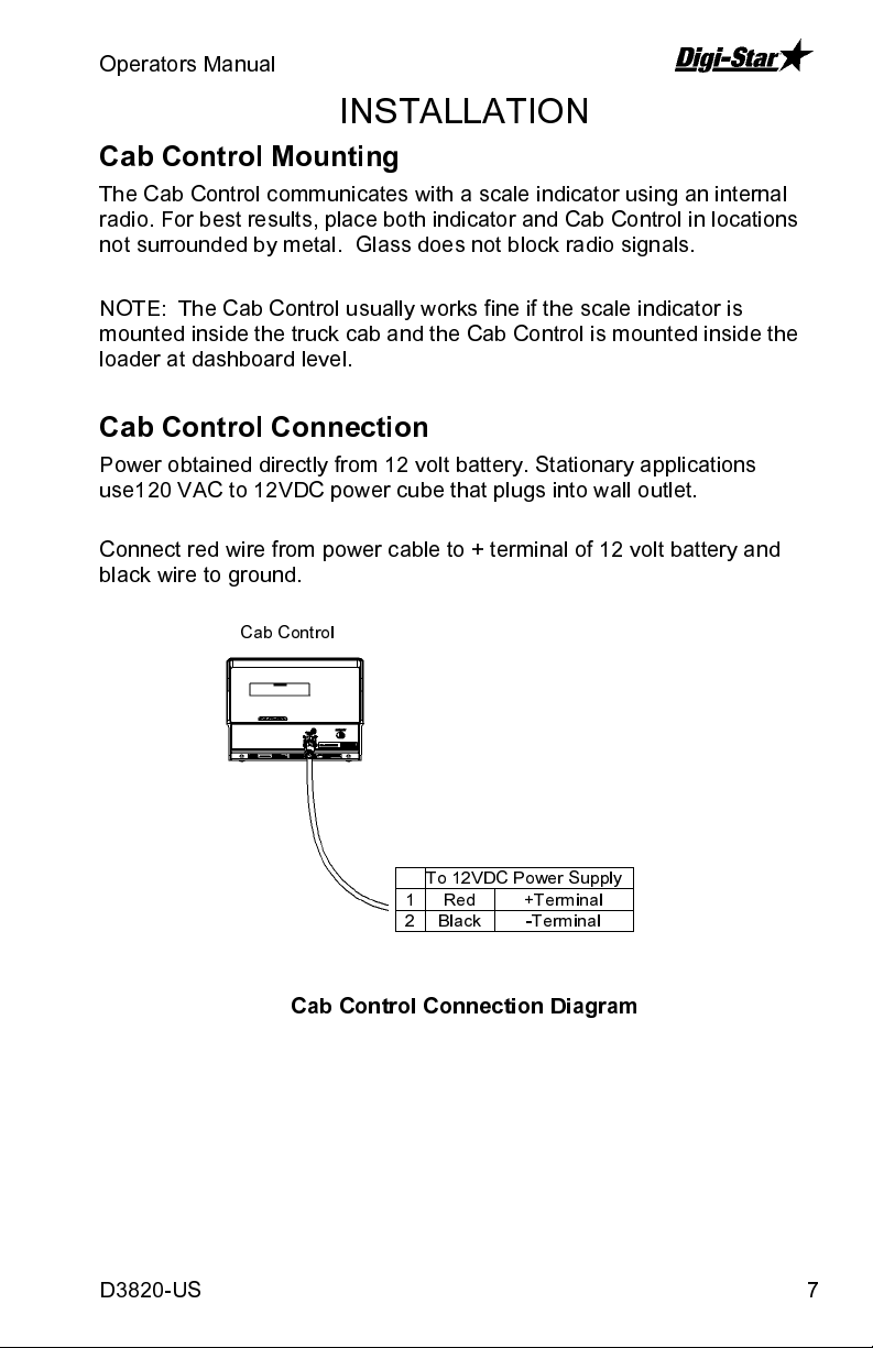
Cab Control Connection
Power obtained directly from 12 volt battery. Stationary applications
use120 VAC to 12VDC power cube that plugs into wall outlet.
Connect red wire from power cable to + terminal of 12 volt battery and
black wire to ground.
Cab Control
To 12VDC Power Supply
Cab Control Connection Diagram
D3820-US 7
1 Red +Terminal
2 Black -Terminal
Page 8

Cab Control
FCC NOTIFICATIONS
FCCID: OUR-24XTREAM
FCC ID: OUR9XSTREAM
This device complies with part 15 of the FCC rules. Operation is subject to
the following conditions:
1. this device may not cause harmful interference
2. this device must not accept any interference received,
including interference that may cause undesirable operation.
To comply with FCC regulations, this device may be used only with
approved antennas. Contact Digi-Star Customer Support for additional
information.
This equipment has been tested and found to comply with the limits for a
Class B digital device, pursuant to Part 15 of the FCC Rules. These limits
are designed to provide reasonable protection against harmful interference
in a residential installation. This equipment generates, uses and can
radiate radio frequency energy and, if not installed and used in accordance
with the instructions, may cause harmful interference to radio
communications. However, there is no guarantee that interference will not
occur in a particular installation. If this equipment does cause harmful
interference to radio or television reception, which can be determined by
turning the equipment off and on, the user is encouraged to try to correct
the interference by one or more of the following measures:
• Re-orient or relocate the receiving antenna.
• Increase the separation between the equipment and receiver.
• Connect the equipment into an outlet on a circuit different from that to
which the receiver is connected.
• Consult the dealer or an experienced radio/TV technician for help.
Caution - This equipment is approved only for mobile and base
transmitting devices, separation distances of (i) 20 centimeters or more for
antennas with gains 6 dbi or (ii) 2 meters or more for antennas with gains =
or > 6 dbi should be maintained between the antenna of this device and
nearby persons during operation. To ensure compliance, operation at
distances closer that this is not recommended.
IMPORTANT: The 9XStream (900 MHz) and 24XStream (2.4 GHz)
Modules have been certified by the FCC for use with other products
without any further certification (as per FCC section 2.1091). Changes or
modifications not expressly approved by MaxStream could void the user’s
authority to operate the equipment.
8
 Loading...