

Page 1
If you have questions or comments, contact us.
Pour toute question ou tout commentaire, nous contacter.
Si tiene dudas o comentarios, contáctenos.
1-800-4-DeWALT • www.dewalt.com
INSTRUCTION MANUAL
GUIDE D’UTILISATION
MANUAL DE INSTRUCCIONES
DWMIIIFN
Hardwood Flooring Tool
Outil pour parquet en bois dur
Herramienta para revestimiento
de piso de madera dura
Page 2
Table of Contents
Safety Instructions ......................................................................3
Operation....................................................................................5
Maintaince ..................................................................................7
Troubleshooting Guide ..............................................................10
Français ....................................................................................12
Español ....................................................................................24
WARNING: BEFORE OPERATING THIS TOOL, ALL OPERATORS SHOULD
STUDY THIS MANUAL TO UNDERSTAND AND FOLLOW THE SAFETY
WARNINGS AND INSTRUCTIONS. KEEP THESE INSTRUCTIONS WITH THE
TOOL FOR FUTURE REFERENCE. IF YOU HAVE ANY QUESTIONS, CONTACT
YOUR DeWALT REPRESENTATIVE OR DISTRIBUTOR.
Definitions: Safety Guidelines
The definitions below describe the level of severity for each signal word.
Please read the manual and pay attention to these symbols.
DANGER: Indicates an imminently hazardous situation which, if not
avoided, will result in death or serious injury.
WARNING: Indicates a potentially hazardous situation which, if not
avoided, could result in death or serious injury.
CAUTION: Indicates a potentially hazardous situation which, if not
avoided, may result in minor or moderate injury.
NOTICE: Indicates a practice not related to personal injury which, if not
avoided, may result in property damage.
Introduction
DeWALT tools are precision-built tools, designed for precise, high volume nailing. These
tools will deliver efficient, dependable service when used correctly and with care. As
with any fine power tool, for best performance the manufacturer’s instructions must be
followed. Please study this manual before operating the tool and understand the safety
warnings and cautions. The instructions on installation, operation and maintenance
should be read carefully, and the manual kept for reference. NOTE: Additional safety
measures may be required because of your particular application of the tool. Contact
your DeWALT representative or distributor with any questions concerning the tool and
its use. DeWALT Industrial Tool Co., 701 East Joppa Road, Towson, MD 21286, call
1-800-4-DeWALT (1-800-433-9258) or visit our website www.dewalt.com.
NOTE: DeWALT tools have been engineered to provide excellent customer satisfaction
and are designed to achieve maximum performance when used with fasteners
engineered to the same exacting standards. DeWALT cannot assume responsibility for
product performance if our tools are used with fasteners or accessories not meeting
the specific requirements established for fasteners, staples and accessories.
2- ENG
Page 3
INTENDED USE
This DWMIIIFN Flooring Tool is intended for use by construction professionals for
installing unfinished hardwood flooring.
Precautions Regarding Use of this Tool to Install Prefinished Flooring
It may also be used to install prefinished wood flooring materials, however precautions
must be taken to assure that the finish will not be damaged by the tool. Before using the
tool on prefinished material, test a sample section to assure that the tool and installation
technique does not leave marks on the finish. This procedure must be followed for every
installation due to variations in flooring materials and condition of the tool.
Do not discharge fasteners into open air, concrete, stone, or any other material too
hard for the fastener to penetrate. Use of this tool by inexperienced operators must be
supervised.
WARNING: Some dust created by power sanding, sawing, grinding, drilling and
other construction activities contains chemicals known to the State of California to
cause cancer, birth defects and other reproductive harm. Some examples of these
chemicals are lead from lead-based paints, crystalline silica from bricks and cement
and other masonry products , and arsenic and chromium from chemically treated
lumber.
Your risk from exposure varies, depending on how often you do this type of work. To
reduce your exposure to these chemicals, work in a well-ventilated area, and work with
approved safety equipment, such as those dust masks that are specially designed to
filter out microscopic particles."
SAFETY INSTRUCTIONS
WARNING: EYE PROTECTION which conforms to ANSI specifications
and provides protection against flying particles both from the FRONT
and SIDE should ALWAYS be worn by the operator and others in the
work area when connecting to air supply, loading, operating or servicing
this tool. Eye protection is required to guard against flying fasteners and
debris, which could cause severe eye injury.
The employer and/or user must ensure that proper eye protection is
worn. Eye protection equipment must conform to the requirements of
the American National Standards Institute, ANSI CAN/CSA Z94.3 and
provide both frontal and side protection. NOTE: Non-side shielded
spectacles and face shields alone do not provide adequate protection.
CAUTION: Additional Safety Protection will be required in some
environments. For example, the working area may include exposure to
noise level which can lead to hearing damage. The employer and user
must ensure that any necessary hearing protection is provided and
used by the operator and others in the work area. Some environments
will require the use of head protection equipment. When required, the
employer and user must ensure that head protection conforming to
ANSI CAN/CSA Z89.1 is used.
Safety Instructions - Air Supply and Connections
WARNING: Do not use oxygen, combustible gases, or bottled gases as a power
source for this tool as tool may explode, possibly causing injury.
WARNING: Do not use supply sources which can potentially exceed 200 p.s.i.g.
(14kg/cm2 ) as tool may burst, possibly causing injury.
WARNING: The connector on the tool must not hold pressure when air supply
is disconnected. If a wrong fitting is used, the tool can remain charged with air
after disconnecting and thus will be able to drive a fastener even after the air line is
disconnected possibly causing injury.
3- ENG
Page 4

WARNING: Always disconnect air supply: 1.) Before making adjustments; 2.)
When servicing the tool; 3.) When clearing a jam; 4.) When tool is not in use; 5.) When
moving to a different work area, as accidental actuation may occur, possibly causing
injury.
Safety Instructions - Loading Tool
WARNING: When loading tool: 1.) Never place a hand or any part of body in
fastener discharge area of tool; 2.) Never point tool at anyone; possibly causing injury.
Safety Instructions - Operation
WARNING: Always handle the tool with care: 1.) Never engage in horseplay; 2.)
Keep others a safe distance from the tool while tool is in operation as accidental
actuation may occur, possibly causing injury.
WARNING: Keep hands and body away from the discharge area of the tool. A
contact arm tool may bounce from the recoil of driving a fastener and an unwanted
second fastener may be driven possibly causing injury.
WARNING: Check operation of the contact arm mechanism frequently. Do not use
the tool if the arm is not working correctly as accidental driving of a fastener may result.
Do not interfere with the proper operation of the contact arm mechanism.
WARNING: Do not drive fasteners on top of other fasteners or with the tool at an
overly steep angle as this may cause deflection of fasteners which could cause injury.
WARNING: Do not drive fasteners close to the edge of the work piece as the wood
may split, allowing the fastener to be deflected possibly causing injury.
WARNING: This nailer produces SPARKS during operation. NEVER use the nailer
near flammable substances, gases or vapors including lacquer, paint, benzine, thinner,
gasoline, adhesives, mastics, glues or any other material that is -- or the vapors, fumes
or byproducts of which are -- flammable, combustible or explosive. Using the nailer
in any such environment could cause an EXPLOSION resulting in personal injury or
death to user and bystanders.
Safety Instructions - Maintaining the Tool
WARNING: When working on air tools note the warnings in this manual and use
extra care when evaluating problem tools.
TOOL SPECIFICATIONS
All dimensions in inches unless otherwise specified
MODEL LENGTH HEIGHT WIDTH WEIGHT
DWMIIIFN
FASTENER SPECIFICATIONS
MODEL FASTENER GAUGE FASTENER
DWMIIIFN
17-1/4"
(438mm)
DWFLN-200 or
FLN-200
11-1/2"
(292mm)
16 Ga. 1-1/2" (38 mm)
3-1/8"
(80mm)
RANGE
to 2" (50 mm)
11.2lbs
(5.1kg)
Tool Air Fitting
This tool uses a 3/8" N.P.T. male plug. The inside diameter should be .275" (7mm) or
larger. The fitting must be capable of discharging tool air pressure when disconnected
from the air supply.
4- ENG
Page 5

Operating Pressure
70 to 90 p.s.i.g. (4.9 to 6.3 kg/cm2). Select the operating pressure within this
range for best fastener performance. DO NOT EXCEED THIS RECOMMENDED
OPERATING PRESSURE.
Air Consumption
The DWMIIIFN requires 4.2 cubic feet per minute (221 liters per minute) of free air to
operate at the rate of 60 fasteners per minute, at 80 p.s.i. (5.6 kg/cm2). Take the actual
rate at which the tool will be run to determine the amount of air required. For instance,
if your fastener usage averages 30 fasteners per minute, you need 50% of the tool’s
c.f.m. of free air which is required to operate the tool at 60 fasteners per minute.
OPERATION
Air Supply and Connections
WARNING: Do not use oxygen, combustible gases, or bottled gases as a
power source for this tool as tool may explode, possibly causing injury.
FITTINGS
Install a male plug on the tool which is free flowing and which will release air pressure
from the tool when disconnected from the supply source.
HOSES
Air hoses should have a minimum of 150 p.s.i. (10.6 kg/cm2) working pressure rating
or 150 percent of the maximum pressure that could be produced in the air system.
The supply hose should contain a fitting that will provide “quick disconnecting” from
the male plug on the tool.
SUPPLY SOURCE
Use only clean regulated compressed air as a power source for this tool. NEVER
USE OXYGEN, COMBUSTIBLE GASES, OR BOTTLED GASES, AS A POWER
SOURCE FOR THIS TOOL AS TOOL MAY EXPLODE.
REGULATOR
A pressure regulator with an operating pressure of 0 - 125 p.s.i. (0 - 8.79 kg/cm2)
is required to control the operat iing pressure for safe operation of this tool. Do not
connect this tool to air pressure which can potentially exceed 200 p.s.i. (14 kg/cm2) as
tool may fracture or burst, possibly causing injury.
OPERATING PRESSURE
Do not exceed recommended maximum operating pressure as tool wear will be greatly
increased. The air supply must be capable of maintaining the operating pressure at the
tool. Pressure drops in the air supply can reduce the tool’s driving power. Refer to Tool
Specifications for setting the correct operating pressure for the tool.
FILTER
Dirt and water in the air supply are major causes of wear in pneumatic tools. A filter will
help to get the best performance and minimum wear from the tool. The filter must have
adequate flow capacity for the specific installation. The filter has to be kept clean to
be effective in providing clean compressed air to the tool. Consult the manufacturer’s
instructions on proper maintenance of your filter. A dirty and clogged filter will cause a
pressure drop which will reduce the tool’s performance.
5- ENG
Page 6
Lubrication
Frequent, but not excessive, lubrication is required for best performance. Use Air Tool
Lubricant, Mobil Velocite #10, or equivalent. Do not use detergent oil or additives as
these lubricants will cause accelerated wear to the seals and bumpers in the tool,
resulting in poor tool performance and frequent tool maintenance. Only a few drops
of oil at a time is necessary. Too much oil will only collect inside the tool and will be
noticeable in the exhaust cycle.
COLD WEATHER OPERATION:
For cold weather operation, near and below freezing, the moisture in the air line may
freeze and prevent tool operation. We recommend the use of winter formula air tool
lubricant or permanent antifreeze (ethylene glycol) as a cold weather lubricant.
NOTICE: Do not store tools in a cold weather environment to prevent frost or ice
formation on the tools operating valves and mechanisms that could cause tool failure.
NOTICE: Some commercial air line drying liquids are harmful to “O”-rings
and seals – do not use these low temperature air dryers without checking
compatibility.
Loading The DWMIIIFN
WARNING: EYE PROTECTION which conforms to ANSI specifications
and provides protection against flying particles both from the FRONT and
SIDE should ALWAYS be worn by the operator and others in the work area
when connecting to air supply, loading, operating or servicing this tool. Eye
protection is required to guard against flying fasteners and debris, which
could cause severe eye injury.
The employer and/or user must ensure that proper eye protection is
worn. Eye protection equipment must conform to the requirements of the
American National Standards Institute, ANSI CAN/CSA Z89.1 and provide
both frontal and side protection. Non-side shielded spectacles and face
shields alone do not provide adequate protection.
WARNING: TO PREVENT ACCIDENTAL INJURIES:
• Never place a hand or any other part of the body in nail discharge area
of tool while the air supply is connected.
• Never point the tool at anyone else.
• Never engage in horseplay.
• Never actuate the tool unless nose is directed at the work.
• Always handle the tool with care.
• Do not actuate the tool while loading.
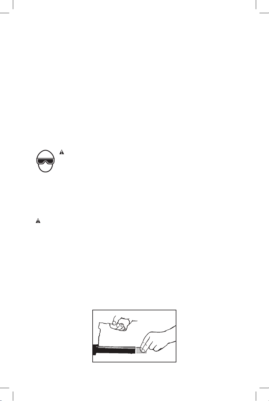
CLEAT LOADING
Insert cleats. Pull pusher assembly back to engage pusher to strip of cleats. Tool is
now ready to operate.
NOTE: Use only cleats recommended for use in the DWMIIIFN nailer or nails which
meet the DeWALT Cleat specifications.
6- ENG
Page 7
BEFORE HANDLING OR OPERATING THIS TOOL
WARNING:
I. READ AND UNDERSTAND THE WARNINGS CONTAINED IN THIS
MANUAL.
II. REFER TO “TOOL SPECIFICATIONS” IN THIS MANUAL TO IDENTIFY
THE OPERATING SYSTEM ON YOUR TOOL.
IN ADDITION TO THE OTHER WARNINGS CONTAINED IN THIS MANUAL
OBSERVE THE FOLLOWING FOR SAFE OPERATION
WARNING:
• Use the DeWALT pneumatic tool only for the purpose for which it was
designed.
• Never use this tool in a manner that could cause a fastener to be
directed toward the user or others in the work area.
• Do not use the tool as a hammer.
• Always carry the tool by the handle. Never carry the tool by the air hose.
• Do not alter or modify this tool from the original design or function
without approval from DeWA LT.
• Always be aware that misuse and improper handling of this tool can
cause injury to yourself and others.
• Before using the tool, verify that the actuator is in the non-actuated
position. With the tool disconnected from the air supply, depress the
actuator and confirm it returns to the non-actuated position.
• Never leave a tool unattended with the air hose attached.
• Do not operate this tool if it does not contain a legible WARNING
LABEL.
• Do not continue to use a tool that leaks air or does not function properly.
Notify your nearest DeWALT representative if your tool continues to
experience functional problems.
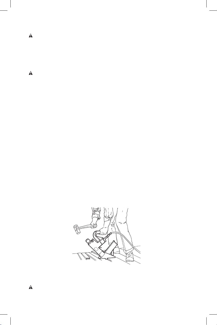
Using the Tool
1. Position the tool on the tongued edge of the flooring strip aligning the driver guide
against the front of the flooring strip.
2. Hold the handle firmly and strike the rubber cap sharply with the rubber end of
the mallet. The tool will then drive the cleat. DO NOT USE THE METAL END OF
THE MALLET TO STRIKE THE RUBBER CAP, use the rubber end only.
MAINTENANCE
Maintaining the Pneumatic Tool
WARNING: Disconnect air line from tool and remove fasteners from magazine
before making adjustments or repairs.
7- ENG
Page 8

WARNING: When working on air tools, note the warnings in this manual and use
extra care evaluating problem tools.
CAUTION: Pusher spring (constant force spring). Caution must be used when
working with the spring assembly. The spring is wrapped around, but not attached
to, a roller. If the spring is extended beyond its length, the end will come off the roller
and the spring will roll up with a snap, with a chance of pinching your hand. Also the
edges of the spring are very thin and could cut. Care must also be taken to insure no
permanent kinks are put in the spring as this will reduce the springs force.
REPLACEMENT PARTS
Use only DeWALT replacement parts.
ASSEMBLY PROCEDURE FOR SEALS
When repairing a tool, make sure the internal parts are clean and lubricated. Use
Parker “O”-LUBE or equivalent on all “O”-rings. Coat each “O”-ring with “O”-LUBE
before assembling. Use a small amount of oil on all moving surfaces and pivots. After
reassembly add a few drops of DeWALT Air Tool Lubricant through the air line fitting
before testing.
AIR SUPPLY-PRESSURE AND VOLUME
Air volume is as important as air pressure. The air volume supplied to the tool may
be inadequate because of undersize fittings and hoses, or from the effects of dirt
and water in the system. Restricted air flow will prevent the tool from receiving an
adequate volume of air, even though the pressure reading is high. The results will be
slow operation, misfeeds or reduced driving power. Before evaluating tool problems for
these symptoms, trace the air supply from the tool to the supply source for restrictive
connectors, swivel fittings, low points containing water and anything else that would
prevent full volume flow of air to the tool.
Maintaining The DWMIII Series Tools
TO REPLACE PISTON
A. Insert the flats on the lower end of the driver piston stem carefully into the end of
piston and plunger wrench, BC1009.
B. Using another special wrench, BC1009, or another wrench of the proper size,
unscrew the plunger from the upper end of the stem. After this is done, it will be
possible to lift the poppet off the stem.
C. Place the special wrench, BC1009, down over the piston stem onto the driver
piston, locking the piston ears in the slots in the wrench. Unscrew the piston from
the stem.
TO REPLACE DRIVER
A. It is not necessary to disassemble the piston-poppet-driver assembly to replace
the driver. Pull the poppet up on the driver piston stem as far as it will go.
B. Insert special wrench, BC1009, over the driver piston, locking the piston ears in
the slots in the wrench. Unscrew the piston from threaded portion of the stem.
C. To remove the driver blade from the piston stem, push the driver blade pin out of
the stem. This will release the blade.
D. Insert new driver blade into the slot in the end of the driver piston stem and
assemble the driver blade pin. Test the side play in the driver blade by grasping the
driver piston stem in one hand and the blade in the other and moving the blade
sideways in alignment with the slot in the stem. There should be a small amount
of side play in the blade. This is necessary to take care of any slight misalignment
between the blade and guide in the nose. If there is no side play, the blade should
8- ENG
Page 9
be removed and the top (pin end) just barely dressed off with a stone. It is not
necessary to do more than smooth off the top to get the necessary side play. Do
not grind. Reinsert the blade and pin in the stem and test for side play once more.
Repeat as necessary to get this small amount of side play. Carefully examine the
large threaded portion of the piston stem. A nylon lock can be seen imbedded in a
recessed hole in the stem. It is very important that this nylon lock can be replaced
when its locking efficiency has been reduced through several disassemblies of the
piston. It is necessary to use the sharp point of a knife, or some such instrument,
to remove this nylon lock. Insert a new one by setting it into the recessed hole in
the stem, and tapping it gently until firmly seated. Reverse these instructions to
reassemble.
E. Assemble plunger flush with end of piston stem.
Accessories
WARNING: Since accessories, other than those offered by DeWALT, have not been
tested with this product, use of such accessories with this tool could be hazardous.
To reduce the risk of injury, only DeWALT recommended accessories should be used
with this product.
Recommended accessories for use with your tool are available at extra cost from
your local dealer or authorized service center. If you need assistance in locating any
accessory, please contact DeWALT Industrial Tool Co., 701 East Joppa Road, Towson,
MD 21286, call 1-800-4-DeWALT (1-800-433-9258) or visit our website: www.dewalt.
com.
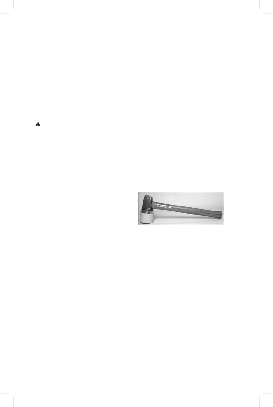
Accessories Available
9R199607 Mallet, wooden
Register Online
Thank you for your purchase. Register your product now for:
• WARRANTY SERVICE: Registering your product will help you obtain more
efficient warranty service in case there is a problem with your product.
• CONFIRMATION OF OWNERSHIP: In case of an insurance loss, such as fire,
flood or theft, your registration of ownership will serve as your proof of purchase.
• FOR YOUR SAFETY: Registering your product will allow us to contact you in the
unlikely event a safety notification is required under the Federal Consumer Safety
Act.
Register online at www.dewalt.com/register.
Seven Year Limited Warranty
DeWA LT will repair, without charge, any defects due to faulty materials or workmanship
for seven years from the date of purchase. This warranty does not cover part failure
due to normal wear or tool abuse. For further detail of warranty coverage and warranty
repair information, visit www.dewalt.com or call 1-800-4-DeWALT (1-800-433-9258).
This warranty does not apply to accessories or damage caused where repairs have
been made or attempted by others. This warranty gives you specific legal rights and
you may have other rights which vary in certain states or provinces.
9- ENG
Page 10
In addition to the warranty, DeWALT tools are covered by our:
1 YEAR FREE SERVICE
DeWA LT will maintain the tool and replace worn parts caused by normal use, for free,
any time during the first year after purchase. Nailer wear items, such as o-rings and
driver blades, are not covered.
90 DAY MONEY BACK GUARANTEE
If you are not completely satisfied with the performance of your DeWA LT Power Tool,
Laser, or Nailer for any reason, you can return it within 90 days from the date of
purchase with a receipt for a full refund – no questions asked.
LATIN AMERICA: This warranty does not apply to products sold in Latin America. For
products sold in Latin America, see country specific warranty information contained in
the packaging, call the local company or see website for warranty information.
FREE WARNING LABEL REPLACEMENT: If your warning labels become illegible or
are missing, call 1-800-4-DeWALT (1-800-433-9258) for a free replacement.
TROUBLESHOOTING GUIDE
PROBLEM CAUSE CORRECTION
Frame/nose leaks air Loose nose screws Tighten and recheck
O-ring or Gasket is cut or
cracked
Bumper cracked/worn Replace bumper
Frame/cap leaks air Damaged gasket or seal Replace gasket or seal
Cracked/worn head valve
bumper
Loose cap screws Tighten and recheck
Failure to cycle Air supply restriction Check air supply
Tool dry, lack of lubrication Use Air Tool Lubricant
Worn head valve O-rings Replace O-rings
Broken cylinder cap spring Replace cylinder cap
Head valve stuck in cap Disassemble/Check/
Replace O-ring or gasket
Replace bumper
equipment
spring
Lubricate
10- ENG
Page 11

PROBLEM CAUSE CORRECTION
Lack of power; slow
to cycle
Tool dry, lacks lubrication Use Air Tool Lubricant
Broken cylinder cap spring Replace cap spring
O-rings/seals cut or cracked Replace O-rings/seals
Exhaust blocked Check bumper, head valve
spring, muffler
Dirt/tar build up on driver Disassemble nose/driver
to clean
Cylinder sleeve not seated
Disassemble to correct
correctlyon bottom bumper
Head valve dry Disassemble/lubricate
Air pressure too low Check air supply
equipment
Skipping fasteners;
intermittent feed
Worn bumper Replace bumper
Tar/dirt in driver channel Disassemble and clean
nose and driver
Air restriction/inadequate air
flow through quick disconnect
Replace quick disconnect
fittings
socket and plug
Worn piston O-ring Replace O-ring, check
driver
Tool dry, lacks lubrication Use Air Tool Lubricant
Damaged pusher spring Replace spring
Low air pressure Check air supply system
to tool
Loose magazine nose screws Tighten all screws
Fasteners too short for tool Use only recommended
fasteners
Bent fasteners Discontinue using these
fasteners
Wrong size fasteners Use only recommended
fasteners
Leaking head cap gasket Tighten screws/replace
gasket
Broken/chipped driver Replace driver (check
piston O-ring)
Dry/dirty magazine Clean/lubricate use Air Tool
Lubricant
Worn magazine Replace magazine
Fasteners jam in tool Driver channel worn Replace nose/check door
Wrong size fasteners Use only recommended
fasteners
Bent fasteners Discontinue using these
fasteners
Loose magazine/nose screws Tighten all screws
Broken/chipped driver Replace driver
11- ENG
Page 12

Table des matières
Instructions De Sécurité............................................................13
Opération..................................................................................15
Maintenance .............................................................................18
Guide De Dépannage ...............................................................22
English ........................................................................................2
Español ....................................................................................24
AVERTISSEMENT: LIRE ATTENTIVEMENT LE PRÉSENT MANUEL AVANT
D’UTILISER L’APPAREIL. PRÉTER UNE ATTENTION TOUTE PARTICULIÈRE
AUX CONSIGNES DE SÉCURITÉ ET AUX AVERTISSEMENTS. GARDER
CE MANUEL AVEC L’OUTIL POUR FUTUR RÉFÉRENCE. SI VOUS AVEZ
DES QUESTIONS, CONTACTEZ VOTRE REPRÉSENTANT OU VOTRE
CONCESSIONNAIRE DeWA LT.
Définitions: lignes directrices en
matière de sécurité
Les définitions ci-dessous décrivent le niveau de danger pour chaque
mot-indicateur employé. Lire le mode d’emploi et porter une attention particulière
à ces symboles.
DANGER: indique une situation dangereuse imminente qui, si elle n’est pas
évitée, entraînera la mort ou des blessures graves.
AVERTISSEMENT : indique une situation potentiellement dangereuse qui,
si elle n’est pas évitée, pourrait entraîner la mort ou des blessures graves.
ATTENTION : indique une situation potentiellement dangereuse qui, si elle
n’est pas évitée, pourrait entraîner des blessures légères ou modérées.
AVIS : indique une pratique ne posant aucun risque de dommages corporels
mais qui par contre, si rien n’est fait pour l’éviter, pourrait poser des risques de
dommages matériels.
Introduction
Les outils DEWALT sont précision construit des outils, conçus pour clouer exactement
un volume élevé de clous. Ces cloueurs sont faits pour assurer un service efficace
et durable, à condition d’être utilisés avec un inimum d’attention et dans des
conditions normales d’utilisation. Comme pour tout autre appareil pneumatique, les
consignes du fabricant doivent être impérativement suivies, afin d’obtenir de bonnes
performances de ce matériel. Lire attentivement le présent manuel avant d’utiliser le
cloueur en prétant une attention toute particulière aux consignes de sécurité. Lire les
instructions concernant l’installation, le fonctionnement et l’entretien de l’appareil.
REMARQUE : des mesures supplémentaires de sécurité peuvent être requises
selon l’usage destiné. Pour toute question concernant l’outil ou son usage,
veuillez contacter votre représentant ou votre concessionnaire. DeWALT
Industrial Tool Co., 701 East Joppa Road, Towson, MD 21286 aux États-Unis;
composer le 1 800 433-9258 (1 800 4-DeWA LT ) ou visiter notre site Web : www.
dewalt.com.
REMARQUE : Les outils DeWALT répondent aux attentes des consommateurs et
offrent des performances optimales, lorsqu’ils sont utilisés en conjonction avec les
dispositifs de fixation obéissant au même standard. Ne garantit pas les performances
de vos outils s’ils sont utilisés avec des dispositifs de fixation ou accessoires ne
répondant pas strictement aux exigences établies en matière de clous, agrafes
etaccessoires.
12- FR
Page 13

USAGE PRÉVU
Cet outil pour parquet DWMIIIFN a été conçu pour les professionnels de la construction
pour installer des parquets en bois dur brut.
Précautions propres à l’utilisation de cet outil pour installer des parquets en
bois préfini
Il peut également être utilisé pour installer des revêtements de sol en bois préfini,
cependant certaines précautions doivent être prises pour assurer que le fini du bois
ne sera pas endommagé par l’outil. Avant d’utiliser l’outil sur des matériaux préfinis,
faire un test sur un rebus pour s’assurer que l’outil et l’installation technique ne
laisseront aucune marque sur le fini. Cette procédure doit être suivie pour chacune des
installations à cause des variations au niveau des revêtements de sol et de la condition
de l’outil.
Ne pas tirer les attaches en l’air, dans le béton, la pierre, ou tout autre matériau trop
dur pour être pénétré par les attaches. L’utilisation de cet outil par des individus non
expérimentés doit se faire sous supervision.
AVERTISSEMENT: certains outils électriques, tels que les sableuses, les scies,
les meules, les perceuses ou autres outils de construction peuvent produire des
poussières contenant des produits chimiques reconnus par l’état californien pour
causer cancers, malformations congénitales ou être nocifs au système reproducteur.
Parmi ces produits chimiques, on retrouve : le plomb dans les peintures à base
de plomb, la silice cristallisée dans les briques et le ciment ou autres articles de
maçonnerie, l’arsenic et le chrome dans le bois traité chimiquement.
Le risque associé à de telles expositions varie selon la fréquence à laquelle on effectue
ces travaux. Pour réduire toute exposition à ces produits: travailler dans un endroit
bien aéré, en utilisant le matériel de sécurité conforme, tel un masque anti-poussières
spécialement conçu pour filtrer les particules microscopiques.
INSTRUCTIONS DE SÉCURITÉ
AVERTISSEMENT: une PROTECTION DES YEUX, conforme aux
normes ANSI et fournissant une protection contre les projectiles en
provenance de l’AVANT et des CÔTÉS, doit TOUJOURS être portée
par l’opérateur et les personnes présentes dans la zone de travail, lors
du raccordement à une source d’air, du chargement, du fonctionnement
et de la maintenance de l’outil. Une telle protection est indispensable
pour vous protéger contre les attaches et débris projetés, susceptibles
d’entraîner des blessures sérieuses.
L’employeur et/ou l’utilisateur doivent s’assurer de porter une bonne
protection oculaire. L’équipement de protection doit être conforme à
la norme ANSI CAN/CSA Z89.3 et doit fournir une protection frontale
et latérale. REMARQUE : Des lunettes sans protection latérale et des
masques faciaux ne fournissent pas la protection nécessaire.
ATTENTION: des mesures de sécurité supplémentaire sont requises
dans certains environnements. Par exemple, la zone de travail peut
favoriser l’exposition à un niveau de bruit susceptible d’entraîner une
surdité. L’employeur et l’utilisateur doivent s’assurer qu’une protection
de l’ouïe sera utilisée par l’opérateur et les personnes présentes dans
la zone de travail. Certains environnements exigeront l’utilisation d’un
équipement de protection de la tête. Lorsque cela s’avère nécessaire,
l’employeur et l’utilisateur doivent s’assurer que la protection de la tête
est conforme à la norme ANSI CAN/CSA Z89.1.
13- FR
Page 14

Instructions de sécurité - Alimentation en air et
connexions
AVERTISSEMENT: n’utilisez jamais de l’oxygène, des gaz combustibles ou des
bouteilles de gaz pour alimenter cet outil; il pourrait exploser et causer des blessures.
AVERTISSEMENT : N’utilisez pas de sources d’alimentation pouvant excéder
200lb/po2 (14 kg/cm2) de pression manométrique; l’outil pourrait exploser et causer
des blessures.
AVERTISSEMENT: le connecteur de l’outil ne doit pas être sous pression après
avoir été déconnecté de l’alimentation d’air. Si un raccord incorrect est utilisé, l’outil
peut rester sous pression après déconnexion et être capable d’enfoncer un dispositif
même si la conduite d’air est déconnectée, occasionnant le cas échéant des blessures.
AVERTISSEMENT: veillez à toujours déconnecter l’alimentation d’air : 1.) Avant
d’effectuer tout réglage; 2.) Lors de la maintenance de l’outil; 3.) Au moment de
déloger une obstruction; 4.) Lorsque l’outil n’est pas utilisé; 5.) Lors du transport de
l’outil dans une autre zone de travail – une mise en marche accidentelle pourrait causer
des blessures.
Instructions de sécurité - Chargement de l’outil
AVERTISSEMENT: lors du chargement de l’outil : 1.) Ne placez jamais une main
ou une partie quelconque du corps sur la trajectoire de sortie des dispositifs de
fixation; 2.) Ne pointez jamais l’outil vers une autre personne – une mise en marche
accidentelle pourrait causer des blessures.
Instructions de sécurité - Fonctionnement
AVERTISSEMENT: veillez à toujours manipuler l’outil avec précaution : 1.) Ne
chahutez pas; 2.) Conservez une distance de sécurité avec l’outil lorsqu’il est en
fonctionnement, car un déclenchement accidentel est possible, et peut occasionner
des blessures.
AVERTISSEMENT : gardez votre corps ainsi que vos mains à l’écart de la
trajectoire de sortie des dispositifs de fixation. Un outil à bras de contact peut rebondir
lors de la fixation d’une attache – une seconde attache indésirable peut alors sortir et
causer des blessures.
AVERTISSEMENT: vérifiez fréquemment le fonctionnement du mécanisme de bras
de contact. N’utilisez pas l’outil si le bras est défaillant, car l’éjection accidentelle d’une
attache peut se produire. N’empêchez pas le bon fonctionnement du mécanisme de
bras de contact.
AVERTISSEMENT: ne fixez pas les dispositifs les uns par-dessus les autres, ou
avec un angle trop prononcé, car ils pourraient dévier et occasionner des blessures.
AVERTISSEMENT: ne fixez pas les dispositifs trop près des bords d’un ouvrage,
car si le bois se fend les dispositifs pourraient dévier et occasionner des blessures.
AVERTISSEMENT : pendant son fonctionnement, cette cloueuse génère des
ÉTINCELLES. NE JAMAIS utiliser la cloueuse près de substances, gaz ou vapeurs
inflammables, y compris : laque, peinture, benzène, solvant, essence, adhésifs,
mastics, colles ou tous autres produits qui sont, eux ou leurs vapeurs, brumes ou
produits dérivés, inflammables, combustibles ou explosifs. L’utilisation de la cloueuse
dans un tel environnement pourrait mener à une EXPLOSION pouvant causer des
blessures ou le décès de l’utilisateur ou de personnes à proximité.
14- FR
Page 15

Instructions de sécurité - Entretien de l’appareil
AVERTISSEMENT: lors de l’utilisation d’un outil fonctionnant sous-pression, lire
les avertissements du manuel et user d’extrêmes précautions lors de la découverte
d’un problème.
SPÉCIFICATIONS DE L’OUTIL
Toutes les mesures des vis et des boulons sont dans le système anglais.
MODELE LONGEUR HAUTEUR LARGEUR POIDS
DWMIIIFN
CARACTÉRISTIQUES DES ÉLÉMENTS D’ASSEMBLAGE
MODELE
DWMIIIFN
438mm
(17-1/4po.)
ELEMENTS
DWFLN-200
ou FLN-200
292mm
(11-1/2po.)
JAUGE ELEMENTS GAMME
16 jauge 38 mm) (1-1/2po.) –
80mm
(3-1/8po.)
50 mm (2po.)
(11,2lbs)
5,1kg
Raccordements à l’air
Cet outil utilise un raccord de 3/8 N.P.T. Son diamètre intérieur doit être de 7 mm
(0,275 po) ou plus. Lors du désaccouplement de la source d’air, le raccord doit
permettre rapidement la mise à l’atmosphère de toute pression résiduelle.
Pression d’utilisation
4,9 à 6,3 kg/cm2 (4,8 bars à 6,2 bars). Régler la pression d’air en suivant ces
recommandations pour obtenir le meilleur rendement possible. NE PAS DÉPASSER
LA PRESSION MAXIMALE RECOMMANDÉE.
Consommation d’air
Le DWMIIIFN consomme 221 l d’air détendu par minute (4,2 pieds cubes/mn) lorsqu’il
fonctionne à la cadence de 60 éléments d’assemblage par minute. On déterminera la
quantité d’air en fonction de la cadence utilisée, par exemple, si la cadence moyenne
est de 30 clous/minute, l’appareil aura besoin de 50% des 221 l d’air par minute, qui
représente la quantité d’air pour une cadence de 60 clous/minute.
OPÉRATION
Alimentation en air et connexions
AVERTISSEMENT: n’utilisez jamais de l’oxygène, des gaz combustibles ou
des bouteilles de gaz comme source d’alimentation pour cet outil; il pourrait
exploser et causer des blessures.
GARNITURES
Installez une fiche mâle sur l’outil capable de délivrer un débit d’air continu et de libérer
la pression d’air de l’outil lorsqu’il est déconnecté de la source d’alimentation.
CONDUITS
Les conduits d’air doivent être soumis à un minimum de 150 lb/po2 (10,6 kg/cm2)
de pression nominale de fonctionnement, ou 150 pour cent de la pression maximum
qui peut être produite par le système d’alimentation d’air. Le conduit d’alimentation
doit contenir une garniture permettant une « déconnexion rapide » de la fiche mâle
del’outil.
15- FR
Page 16

SOURCE D’ALIMENTATION
Veillez à n’utiliser qu’une source d’air comprimé régulée et propre pour alimenter
cet outil. N’UTILISEZ JAMAIS D’OXYGÈNE, DE GAZ COMBUSTIBLES NI DE
BOUTEILLES DE GAZ POUR ALIMENTER CET OUTIL, CAR IL POURRAIT
EXPLOSER.
RÉGULATEUR
Un régulateur de pression capable de maintenir une pression de fonctionnement de
0 à 125 lb/po2 (0 à 8,79 kg/cm2) est requis pour garantir la sécurité d’utilisation de
cet outil. Ne connectez pas cet outil si la pression d’air est susceptible de dépasser
14kg/cm2 (200 lb/po2), car l’outil pourrait exploser et occasionner des blessures.
PRESSION DE FONCTIONNEMENT
Ne dépassez pas la pression de fonctionnement recommandée, car l’usure de l’outil
augmenterait de façon considérable. L’alimentation d’air doit être en mesure de
maintenir la pression de fonctionnement de l’outil. Une baisse de pression subite de
l’alimentation d’air est susceptible de réduire la puissance motrice de l’outil. Consultez
les Spécifications de L’outil pour régler correctement la pression de fonctionnement
de l’outil.
FILTRE
La poussière et la vapeur d’eau dans l’air constituent la cause majeure de l’usure
des outils pneumatiques. L’utilisation d’un filtre permettra d’obtenir de meilleures
performances ainsi qu’une usure minimum de l’outil. Le filtre doit permettre un débit
d’air suffisant pour une installation donnée. Il doit aussi demeurer propre afin de fournir
une source d’air comprimé optimale à l’outil. Consultez les instructions du fabricant
pour assurer une maintenance correcte de votre filtre. Un filtre sale et bouché a pour
effet une baisse de pression susceptible de réduire les performances de l’outil.
Lubrification
Une lubrification fréquente mais sans excès est nécessaire pour assurer un
fonctionnement optimal. Utilisez le lubrifiant pour outil pneumatique, Mobil Velocite
n° 10, ou un équivalent. N’utilisez pas d’huile détergente ni d’additifs. Ces lubrifiants
accélèrent l’usure des joints et des butées de l’outil, ce qui a un effet négatif sur les
performances et la fréquence d’entretien. Quelques gouttes suffisent. Tout excès
s’accumule dans l’outil et apparaîtra lors du cycle d’échappement.
FONCTIONNEMENT EN BASSE TEMPÉRATURE
Pour un fonctionnement par temps froid (une température proche ou inférieure à
0 °C), la conduite d’air peut geler et empêcher le fonctionnement de l’outil. Nous vous
recommandons d’utiliser la formule hivernale du lubrifiant pour outil pneumatique ou, à
défaut, un antigel permanent (éthylène-glycol).
AVIS : Ne stockez pas les outils à basse température afin d’éviter la formation de
gel ou de glace dans les soupapes et mécanismes. Cela pourrait causer un mauvais
fonctionnement de l’outil.
AVIS : Certains liquides commerciaux de séchage de conduite d’air ne
conviennent pas aux joints toriques. Évitez d’utiliser de tels liquides avant de
vous être assuré qu’ils sont compatibles.
Chargement des outils de la DWMIIIFN
AVERTISSEMENT : une PROTECTION DES YEUX, conforme aux
normes ANSI et fournissant une protection contre les projectiles en
provenance de l’AVANT et des CÔTÉS, doit TOUJOURS être portée par
l’opérateur et les personnes présentes dans la zone de travail, lors du
raccordement à une source d’air, du chargement, du fonctionnement et de
la maintenance de l’outil. Une telle protection est indispensable pour vous
16- FR
Page 17

protéger contre les attaches et débris projetés, susceptibles d’entraîner des
blessures sérieuses.
L’employeur et/ou l’utilisateur doivent s’assurer qu’une protection des
yeux est portée. L’équipement de protection doit être conforme à la norme
ANSI CAN/CSA Z89.1 et doit fournir une protection frontale et latérale. Les
lunettes sans coques latérales et les masques faciaux ne fournissent pas la
protection nécessaire.
AVERTISSEMENT: POUR PRÉVENIR TOUT ACCIDENT :
• Ne placez jamais une main ou une partie quelconque du corps dans la
zone de sortie du clou lorsque la source d’alimentation est connectée.
• Ne pointez jamais l’outil vers une autre personne.
• Ne chahutez jamais.
• Ne jamais actionner l’instrument excepté s’il est orienté vers la zone de
travail.
• Veillez à toujours manipuler l’outil avec précaution.
• Ne pas actionner l’instrument lorsqu’il est en charge.
CHARGEMENT DES CLOUS
Insérez les clous. Repoussez le dispositif du poussoir pour l’engager sur la bande de
clous. L’outil est alors prêt à fonctionner.
REMARQUE : utiliser exclusivement les clous recommandés avec l’utilisation de la
cloueuse DWMIIIFN ou les clous conformes aux spécifications DeWALT.
PRÉALABLEMENT À LA MANIPULATION OU À L’UTILISATION DE CET
OUTIL
AVERTISSEMENT:
I. VEILLEZ À LIRE ET COMPRENDRE LES AVERTISSEMENTS CONTENUS
DANS CE MANUEL.
II. REPORTEZ-VOUS AUX SPÉCIFICATIONS DE L’OUTIL DANS CE
MANUEL POUR IDENTIFIER LE PRINCIPE DE FONCTIONNEMENT DE
VOTRE OUTIL.
EN PLUS DES AUTRES AVERTISSEMENTS CONTENUS DANS CE MANUEL,
VEILLEZ À OBSERVER LES PRÉCAUTIONS SUIVANTES
AVERTISSEMENT:
• N’utilisez jamais l’outil pneumatique DeWALT dans un but autre que
celui pour lequel il a été conçu.
• N’orientez jamais l’outil de façon à ce qu’il puisse éjecter une attache en
direction de l’utilisateur ou d’autres personnes dans la zone de travail.
• N’utilisez jamais l’outil comme un marteau.
• Veillez à toujours transporter l’outil à l’aide de la poignée. Ne transportez
jamais l’outil par le conduit d’air.
• Ne modifiez pas la conception ou la fonction originale de l’outil sans
avoir obtenu l’accord de DeWA LT.
17- FR
Page 18

• Gardez toujours présent à l’esprit qu’une utilisation ou une manipulation
incorrecte de cet outil est susceptible d’occasionner des blessures à
vous-même et à d’autres personnes.
• Avant d’utiliser l’outil, assurez-vous que l’actionneur se trouve en
position non actionné. Débranchez l’outil de l’alimentation en air, puis
enfoncez l’actionneur et assurez-vous qu’il revient en position non
actionné.
• Ne laissez jamais un outil sans surveillance avec le conduit d’air
attaché.
• Ne faites pas fonctionner l’outil s’il ne comporte pas une ÉTIQUETTE
D’AVERTISSEMENT lisible.
• Cessez d’utiliser l’outil en cas de fuite d’air ou s’il ne fonctionne pas
correctement. Si le problème
persiste, communiquez avec le représentant DeWALT le plus proche.
Utilisation de l’outil
1. Positionnez l’outil sur la languette de la lame de parquet, en alignant le guide de
course contre la lame de parquet.
2. Maintenez la poignée fermement et donnez un coup sec sur l’embout en
caoutchouc avec l’extrémité en caoutchouc du maillet. L’outil enfoncera alors
le clou. NE PAS UTILISER L’EXTRÉMITÉ MÉTALLIQUE DU MAILLER
POUR TAPER SUR L’EMBOUT EN CAOUTCHOUC, utiliser exclusivement
l’extrémité en caoutchouc.
MAINTENANCE
Maintenance de l’outil pneumatique
AVERTISSEMENT: déconnecter la ligne d’air de l’outil et retirer les attaches du
chargeur avant tout réglage ou toute réparation.
AVERTISSEMENT : lorsque vous travaillez avec des outils pneumatiques,
veuillez observer les avertissements contenus dans le manuel et prêter une attention
redoublée en cas de problème.
ATTENTION: ressort-pousseur (ressort à force constante). Soyez vigilant lorsque
vous utilisez le ressort. Il entoure un cylindre sans y être attaché. Si vous étirez le
ressort au-delà de sa longueur, son extrémité se séparera du cylindre et le ressort
pourrait vous blesser à la main en se rétractant. Notez aussi que les bords effilés du
ressort sont coupants. Vérifiez qu’il n’est pas vrillé, afin qu’il puisse exercer la force
prescrite.
PIÈCES DE RECHANGE
Utiliser exclusivement des pièces de rechange DeWALT.
18- FR
Page 19

PROCÉDURE DE MONTAGE DES JOINTS
Lors de la réparation d’un outil, assurez-vous que les pièces internes sont propres et
lubrifiées. Utilisez le produit « O »-LUBE de Parker ou un équivalent sur tous les joints
toriques. Avant l’assemblage, recouvrez chaque joint torique de lubrifiant. Utilisez
un peu d’huile sur les surfaces mobiles et les axes. Après le réassemblage et avant
de procéder au test, ajoutez quelques gouttes de lubrifiant pour outil pneumatique
DeWALT dans la garniture de conduite d’air.
PRESSION ET VOLUME DE L’ALIMENTATION D’AIR
Le volume d’air est aussi important que la pression. Le volume d’air fourni à l’outil
peut être inadéquat en raison de garnitures et conduits trop justes, ou en raison de la
présence de poussière ou d’eau dans le système. Un débit d’air restreint empêchera
que l’outil reçoive suffisamment d’air, même si la pression est haute. Il en résulte un
fonctionnement ralenti, un défaut d’alimentation ou une force motrice réduite. Avant
de rechercher l’existence éventuelle de ces problèmes, retracez le parcours de
l’alimentation d’air de l’outil à la source. Notez l’existence possible de tout élément
susceptible de diminuer la circulation de l’air vers l’outil, comme un conduit ou une
garniture à rotule obstrués, ou un point inférieur contenant de l’eau.
Entretien des outils de la série DWMIII
POUR REMPLACER LE PISTON
A. Insérer les flasques sur l’extrémité inférieure de la tige de piston d’entraînement
avec précautions dans l’extrémité du piston et la clé de démontage de piston,
BC1009.
B. En utilisant une autre clé spéciale BC1009, ou une autre clé de taille adéquate,
dévisser le piston de la partie supérieure de la tige. Une fois cela fait, il est alors
possible de dégager le manchon de la tige.
C. Placer la clé spéciale BC1009 sur la tige du piston dans le piston d’entraînement,
verrouillant ainsi les épaulements du piston dans les fentes de la clé. Dévisser le
piston de la tige.
POUR REMPLACER L’ENTRAINEMENT
A. Il n’est pas nécessaire de démonter l’ensemble piston, soupape à tige,
entraînement, pour remplacer l’entraînement. Tirer la soupape à tige du piston de
l’entraînement aussi loin que possible.
B. Insérer la clé spéciale BC1009 sur le piston de l’entraînement, verrouillant ainsi les
épaulements du piston dans les fentes de la clé. Dévisser le piston de la portion
filetée de la tige.
C. Pour retirer la lame de l’entraînement de la tige du piston, pousser l’axe de la lame
d’entraînement hors de la tige. Ceci va libérer la lame.
D. Insérer une nouvelle lame d’entraînement dans la fente à l’extrémité de la tige du
piston d’entraînement et monter l’axe de la lame d’entraînement. Vérifier le jeu
latéral de la lame d’entraînement en aggripant la tige de piston d’entraînement
d’une main et la lame de l’autre et en faisant jouer la lame latéralement pour
l’aligner avec la fente de la tige. La lame devrait jouer légèrement. Cette vérification
est nécessaire pour corriger toute erreur d’alignement entre la lame et le guide
du nez. S’il n’existe pas de jeu, la lame doit être retirée et l’extrémité supérieure
(extrémité de l’axe) légèrement parée au moellon. Il n’est pas nécessaire de faire
plus que d’émousser l’extrémité pour obtenir le jeu nécessaire. Ne pas affûter.
Réinsérer la lame et l’axe dans la tige et vérifier le jeu latéral de la lame. Répéter
si nécessaire jusqu’à obtenir le léger jeu latéral. Examiner soigneusement la large
partie effilée de la tige du piston. Un frein en nylon peut être aperçu, encastré dans
une niche de la tige. Il est très important de pouvoir remplacer ce frein quand
19- FR
Page 20

l’efficacité de freinage a diminué à cause de plusieurs démontages du piston. Il
faut utiliser la partie pointue de la lame d’un couteau, ou d’un instrument similaire,
pour retirer le frein en nylon. Insérer un nouveau frein en le plaçant dans la niche
de la tige, et en tapant légèrement dessus jusqu’à ce qu’il soit fermement logé.
Procéder au remontage en refaisant les étapes en sens inverse.
E. Assembler l’enfonceur en l’alignant avec l’extrémité de la tige du piston.
Accessoires
AVERTISSEMENT : puisque les accessoires autres que ceux offerts par DeWALT
n’ont pas été testés avec ce produit, leur utilisation pourrait s’avérer dangereuse.
Pour réduire le risque de blessures, utiliser exclusivement les accessoires DeWALT
recommandés avec le présent produit.
Les accessoires recommandés pour cet outil sont vendus séparément au centre de service
de votre région. Pour obtenir de l’aide concernant l’achat d’un accessoire, communiquer
avec DeWALT Industrial Tool Co., 701 East Joppa Road, Towson, MD 21286 aux États-Unis;
composer le 1 800 433-9258 (1 800 4-DeWA LT ) ou visiter notre site Web : www.
dewalt.com.
Accessoires disponibles
9R199607 Maillet en bois
Registre en ligne
Merci pour votre achat. Enregistrez dès maintenant votre produi:
• RÉPARATIONS SOUS GARANTIE: cette carte remplie vous permettra de vous
prévaloir du service de réparations sous garantie de façon plus efficace dans le cas
d’un probléme avec le produit.
• CONFIRMATION DE PROPRIÉTÉ: en cas de perte provoquée par un incendie,
une inondation ou un vol, cette preuve de propriété vous servira de preuve auprès
de votre compagnie d’assurances.
• SÉCURITÉ: l’enregistrement de votre produit nous permettra de communiquer
avec vous dans l’éventualité peu probable de l’envoi d’un avis de sécurité régi par
la loi fédérale américaine de la protection des consommateurs.
Registre en ligne à www.dewalt.com/register.
Garantie à vie limitée de sept (7) ans
DeWALT réparera gratuitement tous les problèmes dus à des défauts de matériau ou
de fabrication pendant sept (7) ans à compter de la date d’achat. Cette garantie ne
couvre pas des défaillances de pièce dues à une usure normale ou à une mauvaise
utilisation de l’outil. Pour en savoir plus sur la protection et les réparations sous
garantie, visiter le site Web www.dewalt.com ou composer le 1 800 433-9258 (1
800 4-DeWA LT ). Cette garantie ne s’applique pas aux accessoires ni aux dommages
causés par des réparations réalisées ou tentées par des tiers. Cette garantie vous
accorde des droits légaux précis et il est possible que vous ayez d’autres droits qui
varient d’un État ou d’une province à l’autre.
En plus de la garantie, les outils DeWA LT sont couverts par notre:
SERVICE D’ENTRETIEN GRATUIT DE 1 AN
DeWA LT entretiendra l’outil et remplacera les pièces usées par une utilisation normale
et ce, gratuitement, à tout moment pendant la première année à compter de la date
20- FR
Page 21

d’achat. L’usure de pièces comme les joints toriques ou les mécanismes de lames
n’est pas couverte.
GARANTIE DE REMBOURSEMENT DE 90 JOURS
Si vous n’êtes pas entièrement satisfait des performances de votre outil électrique,
laser ou de votre cloueuse DeWA LT pour quelque raison que ce soit, vous pouvez le
renvoyer accompagné d’un reçu dans les 90 jours suivant la date d’achat, et nous
vous rembourserons entièrement – sans poser de questions.
AMÉRIQUE LATINE : Cette garantie ne s’applique pas aux produits vendus en
Amérique latine. Pour ceux-ci, veuillez consulter les informations relatives à la garantie
spécifique présente dans l’emballage, appeler l’entreprise locale ou consulter le site
Web.
REMPLACEMENT GRATUIT DES ÉTIQUETTES D’AVERTISSEMENT : Si
l’étiquette d’avertissement devient illisible ou est manquante, composer le 1 800 4339258 (1 800 4-DeWA LT ) pour un remplacement gratuit.
21- FR
Page 22

GUIDE DE DÉPANNAGE
PROBLÈME CAUSE SOLUTION
Fuite d’air du
châssis/nez de
pose
Fuite d’air
du châssis/
capuchon
Cycle non
amorcé
Manque de
puissance, l’outil
tourne au ralenti
Vis d’assemblage desserrées Resserrez et vérifiez de
nouveau
Le joint torique ou étanche est
coupé ou craquelé
L’amortisseur est craquelé ou
usé
Joint endommagé Remplacez le joint
L’amortisseur de soupape est
craquelé ou trop usé
Vis d’assemblage desserrées Resserrez et vérifiez de
Restriction dans l’alimentation
d’air
L’outil manque de lubrification Utilisez le lubrifiant pour outil
Les joints toriques de la
soupape sont trop usés
Le ressort du chapeau de
bouteille est brisé
La soupape est coincée dans
le chapeau
Outil manquant de lubrification Utilisez le lubrifiant pour outil
Le ressort du chapeau de
bouteille est brisé
Les joints toriques/joints sont
coupés ou craquelés
Échappement bloqué Vérifiez la butée, le ressort de
Des impuretés se sont
accumulées sur le mandrin
La chemise de cylindre n’est
pas correctement placée sur
la butée inférieure
La soupape manque de
lubrification
Pression d’air trop basse Vérifiez l’équipement
Remplacez le joint torique ou
étanche
Remplacez l’amortisseur
Remplacez l’amortisseur
nouveau
Vérifiez l’équipement
d’alimentation d’air
pneumatique
Remplacez les joints toriques
Remplacez le ressort du
chapeau de bouteille
Démontez, vérifiez et lubrifiez
pneumatique
Remplacez le ressort
Remplacez les joints toriques/
joints
soupape, la sourdine
Démontez le nez de pose et le
mandrin afin de les nettoyer
Démontez afin de corriger le
problème
Démontez/lubrifiez
d’alimentation d’air
22- FR
Page 23

PROBLÈME CAUSE SOLUTION
Saut d’attaches;
alimentation
intermittente
Amortisseur usé Remplacez l’amortisseur
Du goudron/des impuretés
se sont accumulés dans la
Démontez le nez de pose et le
mandrin afin de les nettoyer
rainure du mandrin
Alimentation d’air restreinte
ou débit d’air inadéquat dans
Remplacez les raccords de
débranchement rapide
la douille de débranchement
rapide et la fiche
Joint torique du piston trop
usé
Remplacez le joint torique,
vérifiez le mandrin
Outil manquant de lubrification Utilisez le lubrifiant pour outil
pneumatique
Ressort-pousseur
Remplacez le ressort
endommagé
Pression d’air basse Vérifiez le système
d’alimentation d’air vers l’outil
Les vis du nez de pose ou
Resserrez toutes les vis
magasin sont desserrées
Les dispositifs de fixation sont
trop petits pour l’outil
N’utilisez que les dispositifs
recommandés
Dispositifs de fixation pliés Cessez d’utiliser ce type de
dispositif
Taille incorrecte des dispositifs
de fixation
N’utilisez que les dispositifs
recommandés
Le joint statique fuit Serrez les vis et remplacez le
joint statique
Attaches
coincées dans
l’outil
Mandrin brisé ou détérioré Remplacez le mandrin (vérifiez
le joint torique du piston)
Le magasin contient des
impuretés ou n’est pas
suffisamment lubrifié
Nettoyez/lubrifiez; utilisez
le lubrifiant pour outil
pneumatique
Magasin trop usé Remplacez le magasin
Rainure du mandrin usée Remplacez le nez de pose et
vérifiez la porte
Taille incorrecte des dispositifs
de fixation
N’utilisez que les dispositifs
recommandés
Dispositifs de fixation pliés Cessez d’utiliser ce type de
dispositif
Les vis du nez de pose ou
Resserrez toutes les vis
magasin sont desserrées
Mandrin brisé ou détérioré Remplacez le mandrin
23- FR
Page 24

Índice
Instrucciones de Seguridad ......................................................25
Operación .................................................................................27
Mantenimiento ..........................................................................30
Guía de Solución de Problemas ...............................................34
English ........................................................................................2
Français ....................................................................................12
ADVERTENCIA: ANTES DE OPERAR ESTA HERRAMIENTA, TODOS
LOS OPERADORES DEBERÁN ESTUDIAR ESTE MANUAL PARA PODER
COMPRENDER Y SEGUIR LAS ADVERTENCIAS SOBRE SEGURIDAD Y
LAS INSTRUCCIONES. MANTENGA ESTAS INSTRUCCIONES CON LA
HERRAMIENTA PARA FUTURA REFERENCIA, SI TIENE ALGUNA DUDA,
COMUNÍQUESE CON SU REPRESENTANTE DE DeWALT O CON SU
DISTRIBUIDOR.
Definiciones: Normas de seguridad
Las siguientes definiciones describen el nivel de gravedad de cada palabra de
señal. Lea el manual y preste atención a estos símbolos.
PELIGRO: indica una situación de peligro inminente que, si no se evita,
provocará la muerte o lesiones graves.
ADVERTENCIA: indica una situación de peligro potencial que, si no se evita,
podría provocar la muerte o lesiones graves.
ATENCIÓN: indica una situación de peligro potencial que, si no se evita,
posiblemente provocaría lesiones leves o moderadas.
AVISO: se refiere a una práctica no relacionada a lesiones corporales que de
no evitarse puede resultar en daños a la propiedad.
Introducción
Las herramientas DeWALT son herramientas construidas a precisión, diseñadas
para clavar con exactitud un alto volumen de clavos. Estas herramientas entregan
un servicio eficiente y fiable cuando se usan correctamente y con cuidado. Al igual
que con toda herramienta automática de calidad, deben seguirse las instrucciones
del fabricante para obtener el óptimo rendimiento. Estudie este manual antes
de operar la herramienta y tome nota de las advertencias y precauciones de
seguridad. Deben leerse en detalle las instrucciones sobre la instalación, operación
y mantenimiento, y debe conservarse el manual para referencia. NOTA: Pueden
necesitarse medidas adicionales de seguridad según la aplicación particular de
la herramienta. Diríjase al representante o distribuidor de DeWALT si tiene alguna
pregunta referente a la herramienta y su uso. DeWA LT Industrial Tool Co., 701 East
Joppa Road, Towson, MD 21286, llame al 1-800-4-DeWA LT (1-800-433-9258) o
visite nuestro sitio Web: www.dewalt.com.
NOTA: Las herramientas DeWALT se han diseñado para brindar una satisfacción
excelente al cliente y lograr máximo rendimiento al utilizarse con fijaciones diseñadas
con las mismas normas estrictas. No puede asumir responsabilidad alguna por
el rendimiento del producto si se utilizan nuestras herramientas con fijaciones o
accesorios que no reúnen los requisitos específicos establecidos para los clavos,
grapas y accesorios.
24- SP
Page 25

USO PREVISTO
Esta herramienta para revestimiento de piso DWMIIIFN está diseñada para ser
utilizada por profesionales de la construcción para instalar revestimientos de piso de
maderadura.
Precauciones relativas al uso de esta herramienta para instalar revestimientos
de piso prefabricados
Puede utilizarse también para instalar materiales de revestimiento de piso de madera
prefabricado, sin embargo deben tomarse precauciones para asegurar que no se dañe
el acabado con la herramienta. Antes de usar la herramienta en material prefabricado,
pruebe una sección de muestra para verificar que la herramienta y la técnica de
instalación no dejen marcas sobre el acabado. Debe seguirse este procedimiento para
cada instalación debido a las variaciones en los materiales de revestimiento de piso y
al estado de la herramienta.
No descargue clavos directamente al aire, ni sobre hormigón, piedra o cualquier otro
material que sea demasiado duro para que el clavo penetre. Si el operador no tiene
experiencia utilizando esta herramienta, deberá ser supervisado.
ADVERTENCIA: Parte del polvo generado al lijar, serrar, esmerilar y taladrar, así
como al realizar otras actividades de construcción, contiene sustancias químicas
que según el Estado de California causan cáncer, defectos de nacimiento y otras
afecciones reproductivas. Algunos ejemplos de estas sustancias químicas son
el plomo de pinturas a base de plomo, la sílice cristalina de ladrillos y cemento y
otros productos de mampostería, y el arsénico y el cromo de la madera tratada
químicamente.
El riesgo de exposición varía, dependiendo de la frecuencia con que realiza este tipo de
trabajo. Para reducir su exposición a estas sustancias químicas, trabaje en una zona
bien ventilada y utilice un equipo de seguridad aprobado, como mascarillas antipolvo
que estén diseñadas específicamente para filtrar las partículas microscópicas.
INSTRUCCIONES DE SEGURIDAD
ADVERTENCIA: Al cargar, operar o dar servicio a esta herramienta,
el operador y los demás presentes en el área de trabajo deben usar
SIEMPRE PROTECCIÓN DE LOS OJOS en conformidad con las
especificaciones ANSI y que proteja contra partículas que vuelen por
DELANTE y por el LADO, cuando se haga la conexión al suministro de
aire. Se exige protegerse la vista para resguardarse contra fijaciones o
residuos que vuelen, lo cual puede causar lesiones graves a los ojos.
El empleador o el usuario deben asegurar que se protejan debidamente
los ojos. El equipo de protección ocular debe estar en conformidad con
los requisitos del Instituto Nacional Americano de Normas (American
National Standards Institute), ANSI CAN/CSA Z89.3 y proteger por
delante y por el costado. NOTA: Los anteojos o máscaras sin
protección lateral por sí solos no dan una protección adecuada.
ATENCIÓN: En algunos ambientes se necesitará protección
adicional de seguridad. Por ejemplo, el área de trabajo puede exponer
a un nivel de ruido que lesione el oído. El empleador y el usuario deben
comprobar que se cuente con la protección necesaria del oído y que el
operador y los demás presentes en el área la usen. Algunos ambientes
exigirán el uso de casco protector. Cuando sea necesario, el empleado
y el usuario deben verificar que se proteja la cabeza en conformidad
con la norma ANSI CAN/CSA Z89.1.
25- SP
Page 26

Instrucciones de aeguridad - Suministro de aire y
conexiones
ADVERTENCIA: No use oxígeno, gases combustibles ni gases envasados en
cilindros para operar esta herramienta porque puede explotar, causando posibles
lesiones.
ADVERTENCIA: No use fuentes de suministro que tengan el potencial de superar
200 p.s.i.g. (14 kg/cm2) dado que la herramienta puede explotar, causando posibles
lesiones.
ADVERTENCIA: El conector de la herramienta no debe contener presión cuando
se desconecte el suministro de aire. Si se usa el conector indebido, la herramienta
puede mantenerse cargada con aire después de desconectarla y podría impulsar una
fijación incluso después de desconectar la línea de aire, causando posibles lesiones.
ADVERTENCIA: Siempre desconecte el suministro de aire: 1.) Antes de hacer
ajustes; 2.) Al dar servicio a la herramienta; 3.) Al eliminar un atasco; 4.) Cuando no
esté en uso la herramienta; 5.) Al trasladarse a un área de trabajo diferente, porque
puede activarse la unidad casualmente, causando posibles lesiones.
Instrucciones de seguridad - Carga de la
herramienta
ADVERTENCIA: Al cargar la herramienta: 1.) Nunca ponga la mano ni ninguna
parte del cuerpo en el área aplicadora de descarga de la herramienta; 2.) Nunca
apunte la herramienta hacia nadie, causando posibles lesiones.
Instrucciones de seguridad - Funcionamiento
ADVERTENCIA: Siempre maneje la herramienta con cuidado: 1.) Nunca participe
en juegos rudos; 2.) Mantenga a los demás a una distancia segura de la herramienta
mientras esté en funcionamiento porque puede activarse accidentalmente, causando
posibles lesiones.
ADVERTENCIA: Mantenga las manos y el cuerpo alejados del área de descarga
de la herramienta. Una herramienta con brazo de contacto puede rebotar al aplicar
una fijación haciendo salir otra, causando posibles lesiones.
ADVERTENCIA: Revise frecuentemente el funcionamiento del mecanismo del
brazo de contacto. No use la herramienta si el brazo no funciona correctamente ya
que puede impulsarse accidentalmente una fijación. No interfiera con el funcionamiento
adecuado del mecanismo del brazo de contacto.
ADVERTENCIA: No aplique fijaciones unas encima de otras ni con la herramienta
en un ángulo demasiado agudo pues esto puede ocasionar la deflexión de las
fijaciones, pudiendo causar lesiones.
ADVERTENCIA: No aplique fijaciones cerca del borde de la pieza con la cual esté
trabajando pues la madera puede dividirse, permitiendo la deflexión de la fijación,
causando posibles lesiones.
ADVERTENCIA: Esta clavadora produce CHISPAS durante la operación. NUNCA
use la clavadora cerca de sustancias, gases ni vapores inflamables, incluidos
diluyentes, lacas, pintura, bencina, gasolina, adhesivos, mástique, pegamentos ni
ningún otro material que sea inflamable, combustible o explosivo -- o vapores,
emanaciones o subproductos que puedan serlo. Si se usa la clavadora en cualquier
ambiente de este tipo podría causar una EXPLOSION produciendo lesiones físicas o
fatales para el usuario y las personas en la cercanía.
26- SP
Page 27

Instrucciones de seguridad - Mantenimiento de la
herramienta
ADVERTENCIA: Tome nota de las advertencias en este manual al trabajar con
herramientas neumáticas y tenga mayor cuidado al evaluar herramientas problemáticas.
ESPECIFICACIONES DE LA HERRAMIENTA
Todos las medidas de tornillos y tuercas son inglés.
MODELO LARGO ALTURA ANCHO PESO
DWMIIIFN 438mm
(17-1/4")
ESPECIFICACIONES DEL SUJETADOR
MODELO SUJETADORE CALIBRE RANGO DEL SUJETADOR
DWMIIIFN
DWFLN-200 o
FLN-200
292mm
(11-1/2")
16 calibre 38 mm (1-1/2") – 50 mm (2")
80mm
(3-1/8")
5,1kg
(11,2lbs)
Conexión de aire de la herramienta
Esta herramienta usa un enchufe macho de 3/8” N.P.T. El diámetro interior debe ser
de 7,0mm (0,275") o mayor. La conexión debe ser capaz de descargar la presión de
aire de la herramienta cuando es desconectada del suministro de aire.
Presión de operación
4,9 a 6,3 kg/cm2 (4,8 a 6,2 bars). Seleccione la presión de operación dentro de este
rango para el mejor rendimieto. NO EXCEDA ESTA PRESIÓN DE OPERACIÓN
RECOMENDADA.
Consumo de aire
El modelo DWMIIIFN requiere 4,2 pies cúbicos por minuto de aire libre para operar
a razón de 60 clavos por minuto a 5,6 kg/cm2 (5,5 bars) Use la velocidad de clavar
verdadera a la cual se operará la herramienta para determinar la cantidad de aire
requerida. Por ejemplo, si usa un promedio de 30 clavos por minuto, necesitará el
50% de los 4,2pies cúbicos por minuto requeridos para 60 clavos por minuto.
OPERACIÓN
Suministro de aire y conexiones
ADVERTENCIA: No use oxígeno, gases combustibles ni gases envasados
en cilindros para operar esta herramienta porque puede explotar, causando
posibles lesiones.
CONECTORES
Instale un enchufe macho en la herramienta que está fluyendo libremente y que liberará
presión de aire de la herramienta al desconectarse de la fuente de alimentación.
MANGUERAS
Las mangueras de aire deben tener un mínimo de 10.6 kg/cm2 (150 p.s.i.) de
capacidad nominal de presión de trabajo o un 150 por ciento de la presión máxima
que podría producirse en el sistema de aire. La manguera de suministro debe contar
con un conector de “desconexión rápida” del enchufe macho en la herramienta.
27- SP
Page 28

FUENTE DE SUMINISTRO
Use solamente aire comprimido regulado limpio como fuente de energía para esta
herramienta. NUNCA USE OXÍGENO, GASES COMBUSTIBLES O GASES
ENVASADOS EN CILINDROS COMO FUENTE DE ENERGÍA PARA ESTA
HERRAMIENTA, PUES LA HERRAMIENTA PUEDE EXPLOTAR.
REGULADOR
Se necesita un regulador de presión con una presión operativa de 0 - 8,79 kg/cm
2
(0 - 125 p.s.i.) para controlar la presión operativa con el fin de que la herramienta
funcione en forma segura. No conecte esta herramienta a la presión de aire que
potencialmente pueda superar 14 kg/cm2 (200 p.s.i.) pues la herramienta puede
fracturarse o explotar, causando posibles lesiones.
PRESIÓN OPERATIVA
No supere la presión operativa máxima recomendada porque aumentará
considerablemente el desgaste de la herramienta. El suministro de aire debe ser
capaz de mantener la presión operativa de la herramienta. Las caídas de presión en el
suministro de aire pueden reducir la energía impulsora de la herramienta. Consulte las
Especificaciones de la herramienta para establecer la presión operativa correcta
de la herramienta.
FILTRO
La suciedad y el agua en el suministro de aire son las causas principales de desgaste en
las herramientas neumáticas. Resultará útil un filtro para obtener el mejor rendimiento
y minimizar el desgaste de la herramienta. El filtro debe tener una capacidad de flujo
adecuada para la instalación específica. El filtro debe mantenerse limpio para ser eficaz
en el suministro de aire comprimido limpio a la herramienta. Consulte las instrucciones
del fabricante para ver el mantenimiento adecuado del filtro. Si el filtro está sucio y
obstruido ocasionará una caída de presión que a su vez reduce el rendimiento de la
herramienta.
Lubricación
Se necesita una lubricación frecuente, pero no excesiva, para obtener el óptimo
rendimiento. Use el Lubricante para herramientas neumáticas, Mobil Velocite #10
u otro equivalente. No use aceite ni aditivos detergentes porque estos lubricantes
causarán un desgaste acelerado a los sellos y topes de la herramienta, ocasionando
un rendimiento deficiente y mantenimiento frecuente de la herramienta. Solamente
se necesitan unas pocas gotas de aceite a la vez. El exceso de aceite se acumulará
dentro de la herramienta y se notará en el ciclo de escape.
FUNCIONAMIENTO EN CLIMA FRÍO
Para el funcionamiento en clima frío, cerca o bajo cero grados centígrados, la humedad
de la línea de aire puede congelarse e impedir el funcionamiento de la herramienta.
Recomendamos el uso del lubricante invernal para herramientas neumáticas winter
formula o anticongelante permanente (etilenglicol) como lubricante en clima frío.
AVISO: No guarde herramientas en un ambiente de clima frío para evitar la formación
de escarcha o hielo en las válvulas y mecanismos de funcionamiento de las
herramientas que pudieran ocasionarles fallas.
AVISO: Algunos líquidos comerciales secantes de línea de aire son dañinos
para las juntas tóricas y sellos – no use estos secadores de aire de baja
temperatura sin revisar la compatibilidad.
28- SP
Page 29

Carga de las herramientas DWMIIIFN
ADVERTENCIA: Al cargar, operar o dar servicio a esta herramienta, el
operador y los demás presentes en el área de trabajo deben usar SIEMPRE
PROTECCIÓN DE LOS OJOS en conformidad con las especificaciones
ANSI y que proteja contra partículas que vuelen por DELANTE y por el
LADO, cuando se haga la conexión al suministro de aire. Se exige
protegerse la vista para resguardarse contra fijaciones o residuos que
vuelen, lo cual puede causar lesiones graves a los ojos.
El empleador y/o el usuario deben asegurar que se protejan debidamente
los ojos. El equipo de protección ocular debe estar en conformidad con los
requisitos del Instituto Nacional Americano de Normas (American National
Standards Institute), ANSI CAN/CSA Z89.1 y proteger por delante y por el
costado. Las gafas o caretas sin protección lateral por sí solas no dan una
protección adecuada.
ADVERTENCIA: PARA PREVENIR LESIONES ACCIDENTALES:
• Nunca coloque la mano ni ninguna parte del cuerpo en el área de
descarga de clavos de la herramienta mientras esté conectado el
suministro de aire.
• Nunca apunte la herramienta hacia una persona.
• Nunca participe en juegos rudos.
• Nunca active la herramienta a menos que la nariz apunte al lugar de
trabajo.
• Siempre maneje la herramienta con cuidado.
• No active la herramienta mientras la carga.
CARGA DE LOS TACOS
Insertar los tacos. Tirar de la unidad del propulsor hacia atrás para engranar el
propulsor a la tira de tacos. La herramienta está ahora lista para funcionar.
NOTA: Use solamente los tacos recomendados para utilizarse en la clavadora
DWMIIIFN o los clavos que cumplan con las especificaciones de tacos DeWALT.
ANTES DE MANIPULAR U OPERAR ESTA HERRAMIENTA
ADVERTENCIA:
I. LEA DETALLADAMENTE LAS ADVERTENCIAS CONTENIDAS EN ESTE
MANUAL.
II. CONSULTE LAS ESPECIFICACIONES DE LA HERRAMIENTA EN
ESTE MANUAL PARA IDENTIFICAR EL SISTEMA OPERATIVO DE LA
HERRAMIENTA.
29- SP
Page 30

ADEMÁS DE LAS OTRAS ADVERTENCIAS CONTENIDAS EN ESTE MANUAL
OBSERVE LO SIGUIENTE PARA LA OPERACIÓN SEGURA
ADVERTENCIA:
• Use la herramienta neumática DeWALT solamente para el fin que fue
diseñada.
• Nunca use esta herramienta en forma que pueda causar la salida de
una fijación hacia el usuario u otros presentes en el área de trabajo.
• No use la herramienta como martillo.
• Siempre lleve la herramienta tomándola por la empuñadura. Nunca
lleve la herramienta tomándola por la manguera de aire.
• No altere ni modifique el diseño o función original de esta herramienta
sin la aprobación de DeWA LT.
• Siempre tenga presente que el uso indebido o la manipulación
incorrecta de esta herramienta puede causarle lesiones a usted y a los
demás.
• Antes de utilizar la herramienta, verifique que el actuador esté en la
posición no activada. Con la herramienta desconectada del suministro
de aire, presione el actuador y confirme que vuelva a la posición no
activada.
• Nunca deje una herramienta sin supervisión con la manguera de aire
conectada.
• No opere esta herramienta si no cuenta con una ETIQUETA DE
ADVERTENCIA legible.
• Deje de usar la herramienta si tiene fugas de aire o no funciona bien.
Notifique al representante más cercano de DeWALT si la herramienta
sigue presentando problemas funcionales.
Utilización de la herramienta
1. Coloque la herramienta en el borde de lengüeta de la tira de revestimiento de piso
alineando la guía del impulsor contra la parte delantera de la tira de revestimiento
de piso.
2. Sujete el mango firmemente y golpee fuerte la tapa de goma con el extremo de
goma del martillo. La herramienta entonces clavará el taco. NO UTILICE LA
PARTE METÁLICA DEL MARTILLO PARA GOLPEAR LA TAPA DE GOMA,
use solamente el extremo de goma.
MANTENIMIENTO
Mantenimiento de la herramienta neumática
ADVERTENCIA: Desconecte la línea de aire de la herramienta y retire los clavos
del cargador antes de realizar ajustes o reparaciones.
30- SP
Page 31

ADVERTENCIA: Al trabajar con herramientas neumáticas, observe las advertencias
de este manual y tenga sumo cuidado al evaluar herramientas con problemas.
ATENCIÓN: Resorte de empuje (resorte de fuerza constante). Debe tenerse
cuidado al trabajar con el ensamblaje del resorte. El resorte va envuelto alrededor de
un rodillo, no conectado al mismo. Si el resorte se extiende más allá de su longitud, el
extremo se saldrá del rodillo y el resorte se enrollará con un chasquido, posiblemente
pellizcándole la mano. Los bordes del resorte también son muy finos y podrían cortar.
Debe tenerse cuidado para asegurar que no se hagan dobleces permanentes en el
resorte porque esto reducirá la fuerza del mismo.
PIEZAS DE REPUESTO
Use solamente repuestos aprobados por DeWALT.
PROCEDIMIENTO DE ENSAMBLAJE PARA LOS SELLOS
Al reparar una herramienta, fíjese en que las piezas internas estén limpias y lubricadas.
Use Parker “O”-LUBE u otro lubricante equivalente en todas las juntas tóricas. Cubra
cada junta tórica con “O”-LUBE antes del ensamblaje. Use un poco de aceite en todas
las superficies y pivotes móviles. Después del reensamblaje añada unas pocas gotas
de Lubricante para herramientas neumáticas DeWALT (Air Tool Lubricant) a través de
la grasera de la línea de aire antes de probar.
PRESIÓN Y VOLUMEN DEL SUMINISTRO DE AIRE
El volumen de aire es tan importante como la presión de aire. El volumen de aire
suministrado a la herramienta puede ser inadecuado debido a accesorios y mangueras
de tamaño inferior o por los efectos de suciedad y agua en el sistema. El flujo de aire
restringido impedirá que la herramienta reciba un volumen de aire adecuado, aun
cuando la lectura de presión sea alta. Los resultados serán: funcionamiento lento,
fijaciones mal dirigidas o menor potencia de impulso. Antes de evaluar los problemas
de las herramientas según estos síntomas, inspeccione el suministro de aire desde la
herramienta a la fuente de suministro en busca de conectores restrictivos, accesorios
giratorios, puntos bajos que tengan agua y cualquier otra cosa que impida el flujo del
volumen completo de aire a la herramienta.
Mantenimiento de las herramientas de la Serie
DWMIII
PARA REEMPLAZAR EL PISTÓN
A. Inserte con cuidado el extremo plano de la sección inferior del vástago del pistón
del impulsor en el extremo del pistón y de la llave de émbolo, BC1009.
B. Con ayuda de otra llave especial BC1009 u otra de tamaño adecuado, destornille
el émbolo del extremo superior del vástago. Habiendo hecho esto, se podrá
levantar el cabezal del vástago.
C. Coloque la llave especial BC1009 encima del vástago del pistón en el pistón del
impulsor, trabando las orejas del pistón en las ranuras de la llave. Destornille el
pistón del vástago.
PARA REEMPLAZAR EL IMPULSOR
A. No es necesario desmontar el conjunto pistón-cabezal-impulsor para reemplazar
el impulsor. Hale el cabezal hacia arriba en el vástago del pistón del impulsor lo
más que se pueda.
B. Inserte la llave especial BC1009 encima del pistón del impulsor, trabando las
orejas del pistón en las ranuras de la llave. Destornille el pistón para sacarlo de la
parte roscada del vástago.
C. Para separar del vástago del pistón la cuchilla del impulsor, empuje el perno de la
cuchilla del impulsor hacia afuera del vástago. Esto soltará la cuchilla.
31- SP
Page 32

D. Inserte la nueva cuchilla del impulsor en la ranura que se encuentra en el extremo
del vástago del pistón del impulsor y monte el perno de dicha cuchilla del impulsor.
Verifique el juego lateral de la cuchilla del impulsor sujetando el vástago del
pistón del impulsor con una mano y la cuchilla con la otra, moviendo la cuchilla
lateralmente alineada con la ranura del vástago. Debe haber una pequeña cantidad
de juego lateral en la cuchilla. Esto es necesario para compensar cualquier falta de
alineamiento leve entre la cuchilla y la guía en la nariz. Si no hay juego lateral, debe
removerse la cuchilla y pulirse apenas lo suficiente la parte superior (extremo del
perno) con una piedra. No hace falta más que pulir la parte superior para obtener
el juego lateral necesario. No use esmeril. Vuelva a insertar la cuchilla y el perno
en el vástago y verifique de nuevo el juego lateral. Repita este procedimiento hasta
obtener la pequeña cantidad de juego lateral necesaria. Examine con cuidado la
parte grande roscada del vástago del pistón. Podrá observar una traba de nylon
empotrada en un agujero rebajado en el vástago. Es muy importante reemplazar
esta traba de nylon cuando su eficacia de trabado se haya reducido debido a los
repetidos desmontajes del pistón. Para quitar esta traba de nylon, esnecesario
usar la punta afilada de un cuchillo, u otro instrumento parecido. Introduzca
una nueva traba colocándola en el agujero rebajado del vástago y golpeándola
delicadamente hasta que se asiente firmemente. Invierta estas instrucciones para
volver a montar.
E. Monte el émbolo a ras con el extremo del vástago del pistón.
Accesorios
ADVERTENCIA: Debido a que no se han probado con este producto otros
accesorios que no sean los que ofrece DeWALT, el uso de dichos accesorios con esta
herramienta podría ser peligroso. Para reducir el riesgo de lesiones, con este producto
deben usarse sólo los accesorios recomendados por DeWALT.
Los accesorios que se recomiendan para utilizar con la herramienta están
disponibles a un costo adicional en su distribuidor local o en un centro de
mantenimiento autorizado. Si necesita ayuda para localizar algún accesorio,
póngase en contacto con DeWA LT Industrial Tool Co., 701 East Joppa
Road, Towson, MD 21286, llame al 1-800-4-DeWA LT (1-800-433-9258) o
visite nuestro sitio Web: www.dewalt.com.
Accesorios disponibles
9R199607 Martillo, de madera
Registro en línea
Gracias por su compra. Registre su producto ahora para:
• SERVICIO EN GARANTÍA: Si completa esta tarjeta, podrá obtener un servicio
en garantía más eficiente, en caso de que exista un problema con su producto.
• CONFIRMATCIÓN DE PROPIEDAD: En caso de una pérdida que cubra el
seguro, como un incendio, una inundacíon o un robo, el registro de propiedad
servirá como comprobante de compra.
• PARA SU SEGURIDAD: Si registra el producto, podremos comunicarnos con
usted en el caso improbable que se deba enviar una notificación de seguridad
conforme a la Federal Consumer Safety Act (Ley Federal de Seguridad de
Productos para el Consumidor).
Registro en línea en www.dewalt.com/register.
32- SP
Page 33

Garantía limitada por siete años
DeWALT
DeWALT
DeWALT
DeWALT
DeWALT
DeWALT
reparará, sin cargo alguno, los defectos en materiales o por mano de obra
defectuosa por siete años a partir de la fecha de compra. Esta garantía no cubre la
falla de piezas debido al desgaste normal o abuso de la herramienta. Para obtener
más información sobre la cobertura de la garantía y la información de reparación de
la garantía, visite www.dewalt.com o llame al 1 800 433-9258 (1 800 4Esta garantía no se aplica a accesorios o daños causados en caso de que terceros
realicen o intenten realizar reparaciones. Esta garantía le proporciona derechos legales
específicos y usted puede tener otros derechos que varían en ciertos estados o
provincias.
Además de esta garantía, las herramientas
SERVICIO GRATUITO DE 1 AÑO
mantendrá la herramienta y reemplazará las piezas desgastadas por el
uso normal sin costo y en cualquier momento durante el primer año después de la
compra. Los elementos que sufren desgaste de la clavadora, como juntas tóricas y
hojas de transmisión, no están cubiertos.
GARANTÍA DE REEMBOLSO DE 90 DÍAS
Si usted no está completamente satisfecho con el rendimiento de su herramienta
eléctrica, láser o clavadora
los 90 días posteriores a la fecha de compra con un recibo para obtener un reembolso
completo, sin ninguna pregunta.
AMÉRICA LATINA: Esta garantía no es de aplicación a productos vendidos en
América Latina. Para productos vendidos en América Latina, consulte la información
de la garantía específica del país incluida en el embalaje, contacte a la compañía local
o consulte el sitio web para obtener información acerca de la garantía.
REEMPLAZO GRATUITO DE LA ETIQUETA DE ADVERTENCIA: Si sus etiquetas
de advertencia son ilegibles o se extravían, llame al 1 800 433-9258 (1 800 4para obtener un reemplazo gratuito.
por algún motivo, puede devolverlos dentro de
están cubiertas por nuestro:
).
)
33- SP
Page 34

GUÍA DE SOLUCIÓN DE PROBLEMAS
PROBLEMA CAUSA CORRECCIÓN
El armazón o la
punta tiene fuga
de aire
El armazón o la
tapa tiene fuga
de aire
No hace ciclos El suministro de aire está
Falta
alimentación; el
ciclo es lento
Los tornillos de la punta están
sueltos
La junta tórica o la
empaquetadura está cortada
o agrietada
El tope está agrietado o
desgastado
La empaquetadura o el sello
está dañado
El tope de la válvula cabezal
está agrietado o desgastado
Los tornillos de casquete
están sueltos
restringido
La herramienta está seca,
falta lubricación
Las juntas tóricas están
desgastadas en la válvula
cabezal
El resorte en la tapa del
cilindro está roto
La válvula cabezal está
pegada en la tapa
La herramienta está seca,
falta lubricación
El resorte en la tapa del
cilindro está roto
Las juntas tóricas o los sellos
están cortados o agrietados
El escape está bloqueado Revise el tope, el resorte
Hay acumulación de suciedad
o alquitrán en el impulsor
El manguito del cilindro
no está asentado
correctamenteen el tope
inferior
La válvula cabezal está seca Desármela y lubríquela
La presión de aire está
demasiado baja
Apriete y revíselos de nuevo
Cambie la junta tórica o la
empaquetadura
Cambie el tope
Cambie la empaquetadura o
el sello
Cambie el tope
Apriete y revíselos de nuevo
Revise el equipo de
suministro de aire
Use el Lubricante para
herramientas neumáticas
Cambie las juntas tóricas
Cambie el resorte de la tapa
del cilindro
Desarme/Revise/Lubrique lo
necesario
Use el Lubricante para
herramientas neumáticas
Cambie el resorte de la tapa
Cambie las juntas tóricas o
los sellos
de la válvula cabezal, el
silenciador
Desarme la punta o el
impulsor para limpiar
Desármelo para corregir esto
Revise el equipo de
suministro de aire
34- SP
Page 35

PROBLEMA CAUSA CORRECCIÓN
Se saltan
fijaciones; la
alimentación
es interminente
El tope está desgastado Cambie el tope
Hay alquitrán o suciedad en el
canal del impulsor
Restricción de aire/flujo
indebido de aire del enchufe
Desarme y limpie la punta y el
impulsor
Cambie los accesorios de
desconexión rápida
y la toma de desconexión
rápida
Está desgastada la junta
tórica del pistón
La herramienta está seca,
falta lubricación
El resorte de empuje está
Cambie la junta tórica y revise
el impulsor
Use el Lubricante para
herramientas neumáticas
Cambie el resorte
dañado
Hay baja presión de aire Revise el sistema de
suministro de aire a la
herramienta
Los tornillos en la punta del
Apriete todos los tornillos
depósito están sueltos
Las fijaciones son demasiado
cortas para la herramienta
Use solamente las fijaciones
recomendadas
Hay fijaciones dobladas Deje de usar estas fijaciones
Las fijaciones son del tamaño
incorrecto
La empaquetadura de la tapa
cabezal tiene fugas
Use solamente las fijaciones
recomendadas
Apriete los tornillos o cambie
la empaquetadura
El impulsor está roto o picado Cambie el impulsor (revise la
junta tórica del pistón)
El depósito está seco o sucio Limpie/lubrique con
Lubricante para herramientas
neumáticas
El depósito está desgastado Cambie el depósito
Se atascan las
fijaciones en la
herramienta
El canal del impulsor está
desgastado
Las fijaciones son del tamaño
incorrecto
Cambie la punta, revise la
puerta
Use solamente las fijaciones
recomendadas
Hay fijaciones dobladas Deje de usar estas fijaciones
Hay tornillos sueltos en el
Apriete todos los tornillos
depósito o la punta
El impulsor está roto o picado Cambie el impulsor
35- SP
Page 36

DeWALT Industrial Tool Co., 701 East Joppa Road, Towson, MD 21286
(JUN16) Part No. 9R214323 DWMIIIFN Copyright © 2015, 2016 DeWA LT
The following are trademarks for one or more DeWALT power tools: the yellow and
black color scheme; the “D” shaped air intake grill; the array of pyramids on the handgrip; the kit box configuration; and the array of lozenge-shaped humps on the surface
of the tool.
 Loading...