

Page 1
DeWALT
Instruction Manual
Guide D’utilisation
Manual de instrucciones
DWMFN-201
Manual Flooring Cleat Nailer
Clavadora manual para pisos
Cloueuse manuelle de crampons à plancher
If you have questions or comments, contact us.
Pour toute question ou tout commentaire, nous contacter.
Si tiene dudas o comentarios, contáctenos.
1-800-4-
Page 2

INTRODUCTION
DeWALT
DeWALT
DeWALT
DeWALT
DeWALT tools are precision-built tools, designed for precise, high volume nailing. These tools will deliver
efficient, dependable service when used correctly and with care. As with any fine tool, for best performance the
manufacturer’s instructions must be followed. Please study this manual before operating the tool and understand
the safety warnings and cautions. The instructions on installation, operation and maintenance should be read
carefully, and the manual kept for reference. NOTE: Additional safety measures may be required because of
your particular application of the tool. Contact your DeWALT representative or distributor with any questions
concerning the tool and its use. DeWALT Industrial Tool Co., 701East Joppa Road, Towson, MD 21286, call
1-800-4-DeWALT (1-800-433-9258) or visit our website: www.DeWALT.com
INDEX
Safety Instructions ....................................................3
Tool Specifications ....................................................4
Fastener Specifications .................................................4
Tool Setup ..........................................................4
Loading the Tool .....................................................5
Operation ..........................................................6
Ratchet Operation .....................................................6
Fastener Depth .......................................................7
Maintenance .........................................................7
Other DeWALT Products ................................................8
NOTE:
tools have been engineered to provide excellent customer satisfaction and are designed to achieve
maximum performance when used with precision
cannot assume responsibility for product performance if our tools are used with fasteners or
accessories not meeting the specific requirements established for genuine
accessories.
fasteners engineered to the same exacting standards.
nails, staples and
SEVEN YEAR LIMITED WARRANTY
DeWALT will repair, without charge, any defects due to faulty materials or workmanship for seven years from the
date of purchase. This warranty does not cover part failure due to normal wear or tool abuse. For further detail
of warranty coverage and warranty repair information, visit www.dewalt.com or call 1-800-4-DeWALT (1-800433-9258). This warranty does not apply to accessories or damage caused where repairs have been made or
attempted by others. This warranty gives you specific legal rights and you may have other rights which vary in
certain states or provinces.
In addition to the warranty, DeWALT tools are covered by our:
DeWALT will maintain the tool and replace worn parts caused by normal use, for free, any time during the first year
after purchase. Nailer wear items, such as o-rings and driver blades, are not covered.
If you are not completely satisfied with the performance of your DeWALT Power Tool, Laser, or Nailer for any
reason, you can return it within 90 days from the date of purchase with a receipt for a full refund – no questions
asked.
LATIN AMERICA: This warranty does not apply to products sold in Latin America. For products sold in Latin
America, see country specific warranty information contained in the packaging, call the local company or see
website for warranty information.
FREE WARNING LABEL REPLACEMENT: If your warning labels become illegible or are missing, call
1-800-4-DeWALT (1-800-433-9258) for a free replacement.
1 YEAR FREE SERVICE
90 DAY MONEY BACK GUARANTEE
2
Page 3
DeWALT
DEFINITIONS - SAFETY GUIDELINES
The definitions below describe the level of severity for each signal word. Please read the manual and pay attention to these symbols.
Indicates an imminently hazardous situation which, if not avoided, will result in death or
serious injury.
Indicates a potentially hazardous situation which, if not avoided, could result in death
or serious injury.
Indicates a potentially haz ard ous situation which, if not avoided, may result in minor or
mod er ate injury.
Used without the safety alert symbol indicates a situation which, if not avoided, may result
in property damage.
SAFETY INSTRUCTIONS
EYE PROTECTION which conforms to ANSI specifications and provides protection against
flying particles both from the FRONT and SIDE should ALWAYS be worn by the operator
and others in the work area when loading, operating or servicing this tool. Eye protection is
required to guard against flying fasteners and debris, which could cause severe eye injury.
The employer and/or user must ensure that proper eye protection is worn. Eye protection
equipment must conform to the requirements of the American National Standards
Institute, ANSI Z87.1 and provide both frontal and side protection. NOTE: Non-side shielded
spectacles and face shields alone do not provide adequate protection.
Additional Safety Protection will be required in some environments. For
lead to hearing damage. The employer and user must ensure that any necessary hearing
protection is provided and used by the operator and others in the work area. Some
environments will require the use of head protection equipment. When required, the
employer and user must ensure that head protection conforming to ANSI Z89.1 is used.
NEVER USE MALLET WITH A LOOSE HEAD OR SPLINTERED HANDLE.
When loading tool: 1.) Never place a hand or any part of body in fastener discharge area of
tool; 2.) Never point the tool at anyone.
example, the working area may include exposure to noise level which can
Replace worn or damaged parts immediately.
To avoid accidental injury, to yourself and others, bystanders must maintain
a safe distance from you, during use of this tool especially when swinging
the mallet.
The operator should always wear safety shoes.
Use only cleats manufactured from
Never hit the plunger with the metal face of the mallet.
.
LOADING TOOL
OPERATION
Always handle the tool with care: 1.) Never engage in horseplay; 2.) Never actuate the tool
unless fastener discharge area of tool is directed toward the work; 3.) Keep others a safe
distance from the tool while tool is in operation as accidental actuation may occur, possibly
causing injury.
Keep hands and body away from the discharge area of the tool.
Do not drive fasteners on top of other fasteners or with the tool at an overly steep angle as
this may cause deflection of fasteners which could cause injury.
Do not drive fasteners close to the edge of the work piece as the wood may split, allowing
the fastener to be deflected possibly causing injury.
This tool produces SPARKS during operation. NEVER use the tool near flammable
substances, gases or vapors including lacquer, paint, benzine, thinner, gasoline, adhesives,
mastics, glues or any other material that is - or the vapors, fumes or by-products of which
are -- flammable, combustible or explosive. Using the tool in any such environment could
cause an EXPLOSION resulting in personal injury or death to user and bystanders.
MAINTAINING THE TOOL
When working on tools note the warnings in this manual and use extra care when
evaluating problem tools.
3
Page 4
DWMFN-201 TOOL SPECIFICATIONS
All dimensions in inches unless otherwise specified
DWMFN-201
Description Manual Flooring Nailer
Fastener Type “L” Type 16 Gauge Flooring Cleats
Magazine Capacity 120 cleats
Length 13-7/16" (340mm)
Width 3-1/2" (89mm)
Height 17-1/2" (444mm)
Weight 8.6 lbs (3.9kg)
DWMFN-201 FASTENER SPECIFICATIONS
Tool Model Fastener Type Fastener SKU Gauge Length
DWMFN-201 Manual DWFLN-150 16 1-1/2” (38.1mm)
DWFLN-200 16 2” (50.8 mm)
NOTE:
DeWALT tools have been engineered to provide superior customer satisfaction and are designed to achieve
maximum performance when used with precision DeWALT fasteners engineered to the same exacting standards.
DeWALT cannot assume responsibility for product performance if our tools are used with fasteners
or accessories not meeting the specific requirements established for genuine DeWALT fasteners and
accessories.
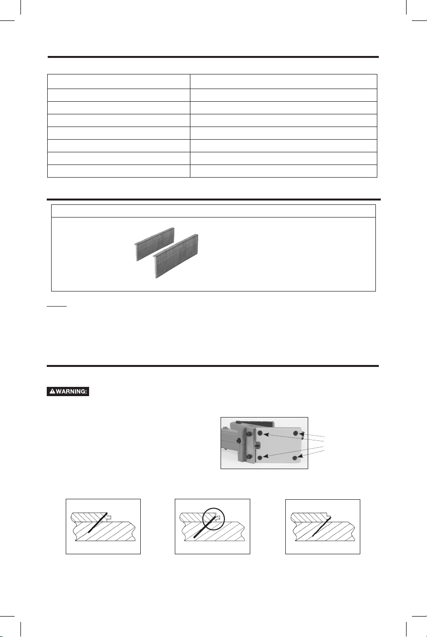
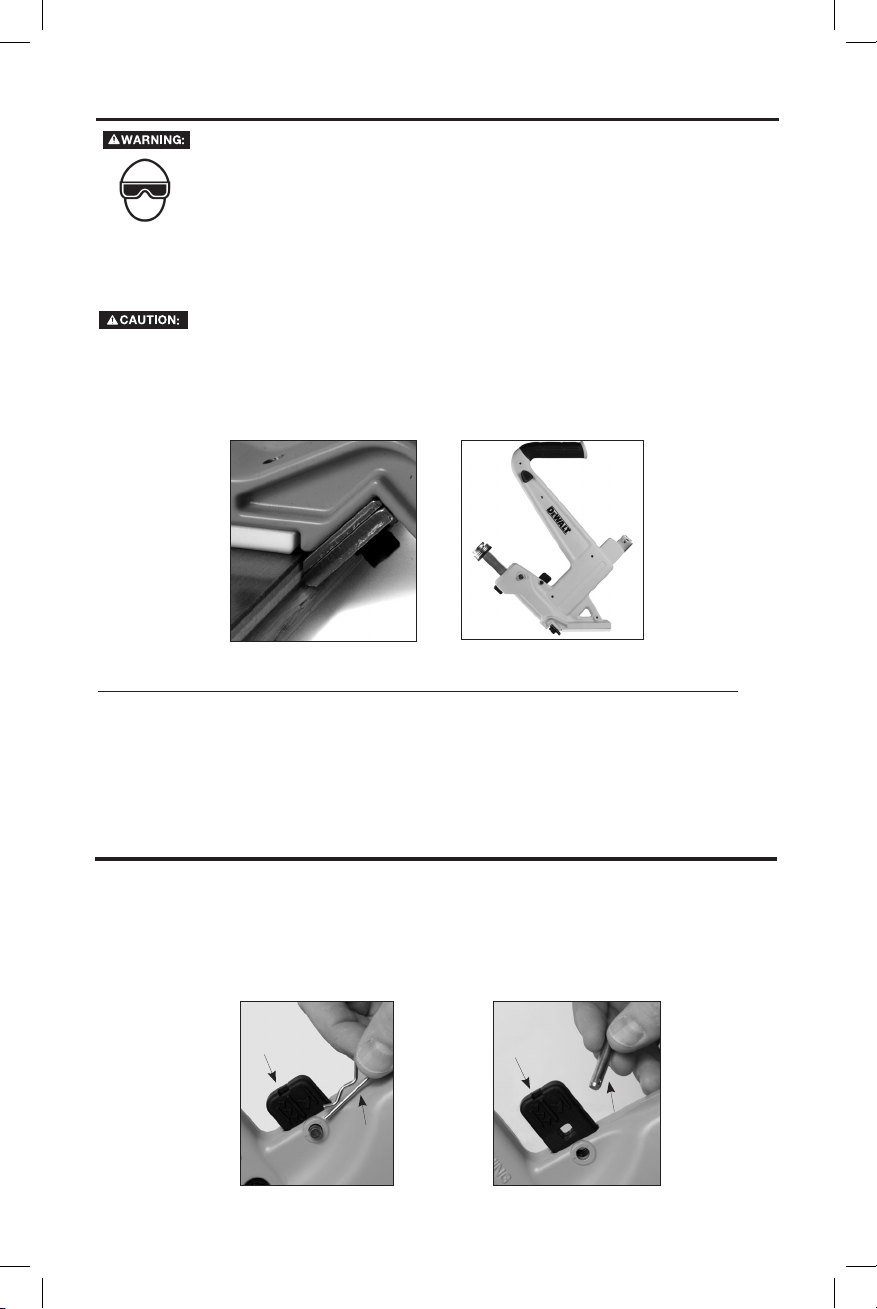
TOOL SETUP
The DWMFN-201 was designed to install 1/2” to 3/4” tongue and groove hardwood flooring. The tool is factory set for
3/4” flooring. Two additional foot plates are included with this tool to accommodate 1/2” and 5/8” flooring.
Flooring products will vary and the user must ensure the tool is properly adjusted each time
flooring is being installed. Dimensions listed on the footplates are suggestions. Test fastener
placement on scrap pieces of wood before installing floor.
To change footplates:
1. Remove 4 flat head cap screws.
2. Change to desired plate.
3. Replace 4 flat head cap screws.
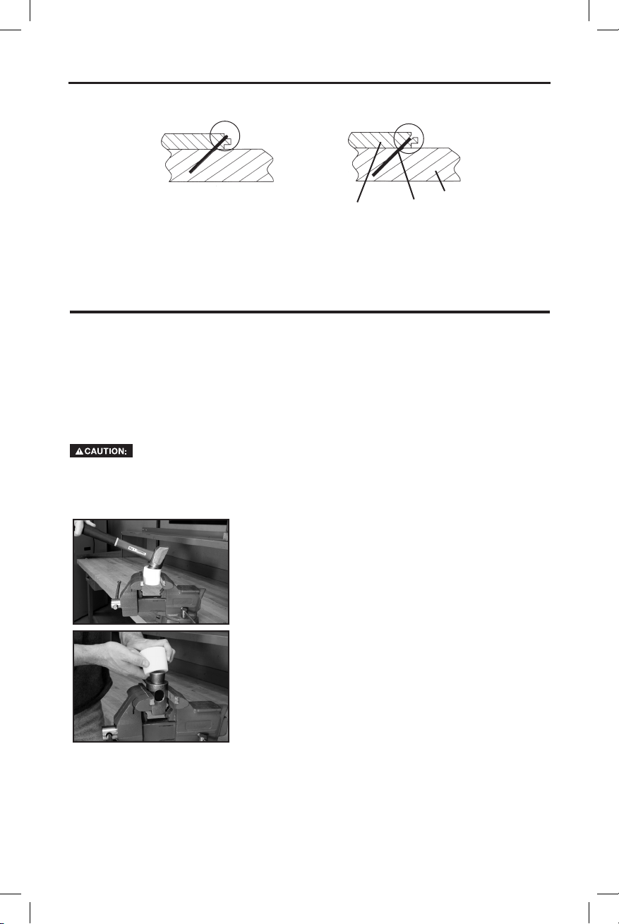
FASTENER PLACEMENT:
Too High Correct Too Low
4
Flat head
cap screws
Page 5
LOADING THE DWMFN-201
EYE PROTECTION which conforms to ANSI specifications and provides protection against
flying particles both from the FRONT and SIDE should ALWAYS be worn by the operator
and others in the work area when loading, operating or servicing this tool. Eye protection
is required to guard against flying fasteners and debris, which could cause severe eye
injury.
The employer and/or user must ensure that proper eye protection is worn. Eye protection
equipment must conform to the requirements of the American National Standards Institute,
ANSI Z87.1 and provide both frontal and side protection. NOTE: Non-side shielded spectacles
and face shields alone do not provide adequate protection.
TO PREVENT ACCIDENTAL INJURIES:
• Never place a hand or any other part of the body in nail discharge area of tool.
• Never point the tool at anyone else.
• Never engage in horseplay.
• Always handle the tool with care.
• Do not contact the actuator while loading the tool.
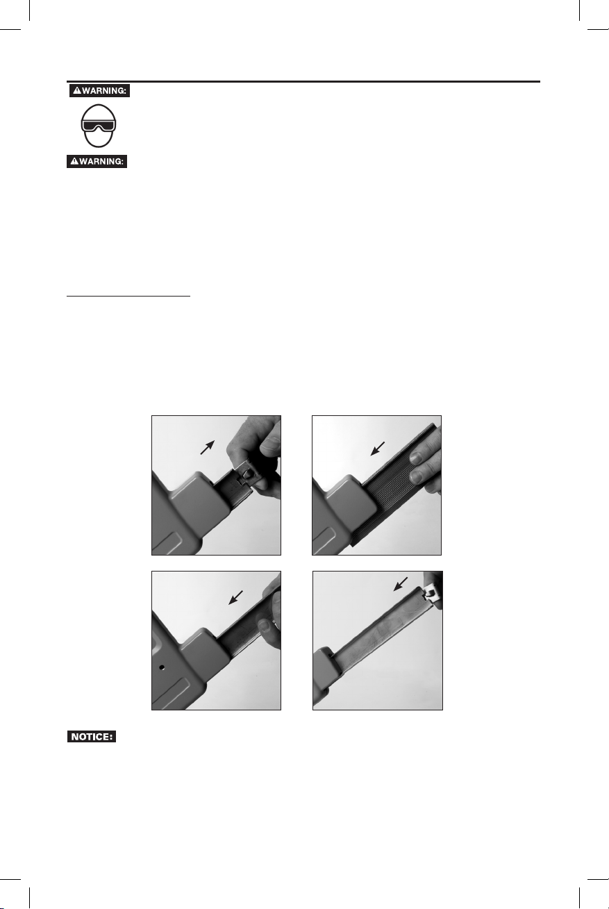
LOADING THE TOOL
1. Release the pusher spring clip and remove the pusher blade.
2. Load the fasteners into guide channel.
3. Insert rounded end of pusher blade into channel to retain fasteners.
4. Latch pusher spring clip to notched end of pusher blade. Ensure sufficient engagement of pusher blade for
smooth fastener feeding.
1.
3.
FASTENER MAY NOT FEED CONSISTENTLY IF PUSHER BLADE IS NOT INSTALLED.
BEFORE HANDLING OR OPERATING THIS TOOL READ AND UNDERSTAND THE WARNINGS
CONTAINED IN THIS MANUAL.
2.
4..
5
Page 6
DeWALT
DeWALT
OPERATION
EYE PROTECTION which conforms to ANSI specifications and provides protection against
flying particles both from the FRONT and SIDE should ALWAYS be worn by the operator
and others in the work area when loading, operating or servicing this tool. Eye protection
is required to guard against flying fasteners and debris, which could cause severe eye
injury.
The employer and/or user must ensure that proper eye protection is worn. Eye protection
equipment must conform to the requirements of the American National Standards Institute,
ANSI Z87.1 and provide both frontal and side protection. NOTE: Non-side shielded spectacles
and face shields alone do not provide adequate protection.
The DWMFN-201 was designed to install 1/2” - 3/4” tongue and groove hardwood flooring.
NOTE: Always test on a scrap piece of flooring.
NEVER HIT THE PLUNGER WITH THE METAL END OF THE MALLET.
1. Position the flooring per the manufacture’s specifications.
2. Place the tool with the guide plate above the tongue and firmly against the forward face of the flooring material.
3. Ensure that the foot plate is firmly held against the top surface of the flooring.
4. Using the rubber face of the mallet strike the top end of the metal plunger.
2.
NOTE: Sufficient force is required to completely drive a single fastener with one strike of the mallet .
4.
NOTE: REGARDING THE USE OF THIS TOOL TO INSTALL PRE-FINISHED FLOORING
The
flooring products, including pre-finished flooring. Due to the ever changing products and manufacturing processes
used in producing pre-finished hardwood flooring, caution must be used to ensure that the flooring finish is not
damaged by the tool. Always test the tool and installation technique on a sample section of flooring to be certain
that both the tool and the installation technique do not damage the pre-finished flooring. This procedure should be
followed before each job due to variations in flooring and tool condition.
for any flooring damage.
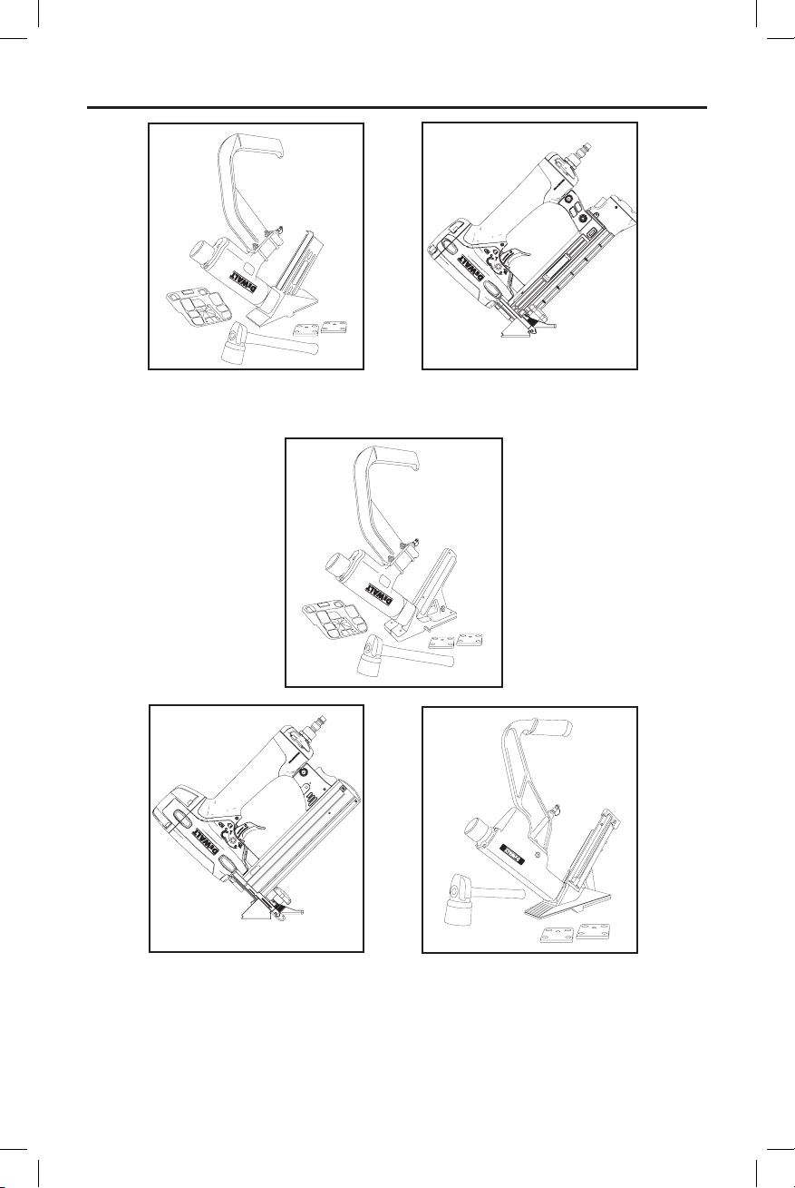
RATCHET OPERATION
To change drive mode:
1. Remove the cotter pin and then the clevis pin.
2. Position ratchet mechanism.
• For ratcheting (multi-blow) operation, set as shown in Fig. 1.
• For non-ratcheting (single-blow) operation, set as shown in Fig. 2.
3. Replace clevis pin and the cotter pin after adjustment.
DWMFN-201 has been precisely engineered to be compatible with today’s vast array of hardwood
cannot assume responsibility
Ratcheting
Cotter
pin
Fig. 1
NONRatcheting
Clevis
pin
Fig. 2
6
Page 7
FASTENER DEPTH
DeWALT
UNDER DRIVEN FASTENER
In ratchet mode, if the plunger does not fully return the nail has not been completely driven. When this happens,
use the rubber face of the mallet to strike the top end of the metal plunger again. When the nail is completely
driven the ratcheting mechanism will allow the plunger to return.
PROPERLY DRIVEN FASTENER
Floor
Fastener
Sub Floor
MAINTENANCE
Tool
As with any quality tool regular maintenance will improve its operation and life span.
are recommended. Do not use modified parts or parts which will not give equivalent performance to the original
equipment.
1. To inspect or replace any parts of the plunger, first remove the retaining clip and pull out the locking pin.
2. Pull out the plunger assembly.
3. Clean old grease, dirt and abrasive particles off of all parts.
4. Replace all damaged or worn parts.
WHEN REPLACING THE DRIVER BLADE, ENSURE THAT THE WORD “FRONT” STAMPED
ON THE BLADE IS VISIBLE AFTER YOU HAVE INSTALLED IT ON THEPLUNGER.
Mallet
Over time the rubber face on the mallet may became worn, cracked, or chipped. These are signs that a new
rubber face will need to be installed.
Remove old rubber face:
1. Secure the rubber face in a bench vise.
2. Pull upward on the handle till the rubber face is released from the steel
stud.
To install a new rubber face on the mallet, we recommend doing it in the
shop with the use of an arbor press. If you must do it manually follow
these instructions.
1. Secure the mallet head in a bench vise.
2. Put the rubber cap slightly inclined on top of the steel stud, push
downward with a twisting motion to engage the rubber cavity
over the edge of the steel stud.
3. Once fully engaged over the edge, you can release the mallet
from the vise and hit it on solid surface to properly seat the rubber
face on the mallet head.
replacement parts
7
Page 8
DeWALT
OTHER
DeWALT
FLOORING PRODUCTS
DWMIIIFS
15.5 GAUGE
FLOORING STAPLER
20 GAUGE FLOORING STAPLER
DWLHF2025K
DWMIIIFN
16 GAUGE
FLOORING NAILER
DWEHF1838K
18 GAUGE MANUAL
FLOORING STAPLER
2-IN-1 15.5 GAUGE FLOORING
STAPLER AND 16 GAUGE
CLEAT NAILER
For more information log on to: www.
8
DWFP12569
.com
Page 9

INTRODUCCIÓN
DeWALT
DeWALT
DeWALT
DeWALT
DeWALT
DeWALT
Las herramientas DeWALT son herramientas construidas a precisión, diseñadas para clavar con exactitud
un alto volumen de clavos. Estas herramientas entregan un servicio eficiente y fiable cuando se usan
correctamente y con cuidado. Al igual que con toda herramienta de calidad, deben seguirse las instrucciones
del fabricante para obtener el óptimo rendimiento. Estudie este manual antes de operar la herramienta y
tome nota de las advertencias y precauciones de seguridad. Deben leerse en detalle las instrucciones sobre
la instalación, operación y mantenimiento, y debe conservarse el manual para referencia. NOTA: Pueden
necesitarse medidas adicionales de seguridad según la aplicación particular de la herramienta. Diríjase al
representante o distribuidor de DeWALT si tiene alguna pregunta referente a la herramienta y su uso. DeWALT
Industrial Tool Co., 701 East Joppa Road, Towson, MD 21286, llame al 1-800-4-DeWalt (1-800-433-9258) o
visite nuestro sitio Web: www.dewalt.com.
Instrucciones de seguridad .............................................10
Especificaciones de la herramienta ......................................11
Especificaciones de fijaciones ...........................................11
Configuración de la herramienta..........................................11
Carga de la herramienta ..............................................12
Funcionamiento ......................................................13
Operación de trinquete ................................................13
La profundidad de la fijación ............................................14
M antenimiento ......................................................14
Otros productos DeWALT ..............................................15
Las herramientas DeWALT se han diseñado para brindar una satisfacción excelente al cliente y lograr máximo
rendimiento al utilizarse con fijaciones de precisión DeWALT diseñadas con las mismas normas estrictas. DEWALT
no puede asumir responsabilidad alguna por el rendimiento del producto si se utilizan nuestras
herramientas con fijaciones o accesorios que no reúnen los requisitos específicos establecidos para
los clavos, grapas y accesorios genuinos de DeWA LT.
GARANTÍA LIMITADA POR SIETE AÑOS
reparará, sin cargo alguno, los defectos en materiales o por mano de obra defectuosa por siete años
a partir de la fecha de compra. Esta garantía no cubre la falla de piezas debido al desgaste normal o abuso de
la herramienta. Para obtener más información sobre la cobertura de la garantía y la información de reparación
de la garantía, visite www.dewalt.com o llame al 1 800 433-9258 (1 800 4a accesorios o daños causados en caso de que terceros realicen o intenten realizar reparaciones. Esta garantía
le proporciona derechos legales específicos y usted puede tener otros derechos que varían en ciertos estados
o provincias.
Además de esta garantía, las herramientas
están cubiertas por nuestro:
). Esta garantía no se aplica
ÍNDUCE
NOTA
SERVICIO GRATUITO DE 1 AÑO
mantendrá la herramienta y reemplazará las piezas desgastadas por el uso normal sin costo y en
cualquier momento durante el primer año después de la compra. Los elementos que sufren desgaste de la
clavadora, como juntas tóricas y hojas de transmisión, no están cubiertos.
GARANTÍA DE REEMBOLSO DE 90 DÍAS
Si usted no está completamente satisfecho con el rendimiento de su herramienta eléctrica, láser o clavadora
por algún motivo, puede devolverlos dentro de los 90 días posteriores a la fecha de compra con un
recibo para obtener un reembolso completo, sin ninguna pregunta.
AMÉRICA LATINA: Esta garantía no es de aplicación a productos vendidos en América Latina. Para productos
vendidos en América Latina, consulte la información de la garantía específica del país incluida en el embalaje,
contacte a la compañía local o consulte el sitio web para obtener información acerca de la garantía.
REEMPLAZO GRATUITO DE LA ETIQUETA DE ADVERTENCIA: Si sus etiquetas de advertencia son ilegibles
o se extravían, llame al 1 800 433-9258 (1 800 4-
) para obtener un reemplazo gratuito.
9
Page 10

ATENCIÓN:
ATENCIÓN:
DeWALT
Las siguientes definiciones describen el nivel de gravedad de cada advertencia. Lea el manual y preste
ATENCIÓN:
atención a estos símbolos.
Indica una situación de peligro inminente que, si no se evita,
provocará la muerte o
lesiones graves.
Indica una situación de peligro potencial que, si no se evita,
podría
provocar la
muerte o lesiones graves.
Indica una situación de peligro potencial que, si no se evita,
puede
provocar
lesiones
leves o moderadas.
Si se utiliza sin el símbolo de alerta de seguridad, indica una situación que si no se evita,
resultar en
daño a la propiedad
.
puede
INSTRUCCIONES DE SEGURIDAD
PAUTAS DE SEGURIDAD/DEFINICIONES
Al cargar, operar o dar servicio a esta herramienta, el operador y los demás presentes en
el área de trabajo deben usar SIEMPRE PROTECCIÓN DE LOS OJOS en conformidad con
las especificaciones ANSI y que proteja contra partículas que vuelen por DELANTE y por
el LADO. Se exige protegerse la vista para resguardarse contra fijaciones o residuos que
vuelen, lo cual puede causar lesiones graves a los ojos.
El empleador o el usuario deben asegurar que se protejan debidamente los ojos. El equipo
de protección ocular debe estar en conformidad con los requisitos del Instituto Nacional
Americano de Normas (American National Standards Institute), ANSI Z87.1 y proteger por
delante y por el costado. NOTA: Los anteojos o máscaras sin protección lateral por sí solos
no dan una protección adecuada.
ATENCIÓN:
dañar el oído. El empleador y el usuario deben asegurarse de que cualquier protección necesaria para
los oídos sea provista y utilizada por el operador y demás personas en el área de trabajo. Algunos
entornos requieren el uso de aparatos de protección para la cabeza. Cuando sea necesario, el
empleador y el usuario deben asegurarse de que se utilice protección para la cabeza en conformidad
con la norma ANSI Z89.1.
NUNCA USE EL MAZO SI TIENE LA CABEZA SUELTA O EL MANGO ASTILLADO.
ATENCIÓN:
ATENCIÓN:
ATENCIÓN:
AL CARGAR LA HERRAMIENTA
Al cargar la herramienta: 1.) Nunca coloque una mano o cualquier otra parte del cuerpo en el
área de descarga del sujetador de la herramienta; 2.) Nunca apunte la herramienta hacia otra
persona.
En algunos entornos será necesaria protección de seguridad adicional. Por ejemplo,
es posible que el área de trabajo incluya la exposición a niveles de ruido que pueden
Reemplace las piezas desgastadas o dañadas inmediatamente.
Para evitar lesiones accidentales, a usted y otros, los presentes en la
cercanía deben mantenerse a distancia segura de usted durante el uso de
esta herramienta especialmente al utilizar el mazo.
El operador debe usar siempre zapatos de seguridad.
Use solamente clavos fabricados por
Nunca golpee el émbolo con la cara de metal del mazo.
.
OPERACIÓN
Siempre maneje la herramienta con cuidado: 1.) Nunca participe en juegos rudos; 2.) Nunca accione
el gatillo a menos que la punta esté dirigida hacia el trabajo; 3.) Mantenga a los demás a una distancia
segura de la herramienta mientras esté en funcionamiento porque puede activarse accidentalmente,
causando posibles lesiones.
Mantenga las manos y el cuerpo alejados del área de descarga de la herramienta.
No aplique fijaciones unas encima de otras ni con la herramienta en un ángulo demasiado agudo pues
esto puede ocasionar la deflexión de las fijaciones, pudiendo causar lesiones.
No aplique fijaciones cerca del borde de la pieza con la cual esté trabajando pues la madera puede
dividirse, permitiendo la deflexión de la fijación, causando posibles lesiones.
Esta clavadora produce CHISPAS durante la operación. NUNCA use la clavadora cerca de sustancias,
gases ni vapores inflamables, incluidos diluyentes, lacas, pintura, bencina, gasolina, adhesivos, mástique,
pegamentos ni ningún otro material que sea inflamable, combustible o explosivo -- o vapores, emanaciones
o subproductos que puedan serlo. Si se usa la clavadora en cualquier ambiente de este tipo podría causar
una EXPLOSION produciendo lesiones físicas o fatales para el usuario y las personas en la cercanía.
MANTENIMIENTO DE LA HERRAMIENTA
Al trabajar con herramientas, observe las advertencias de este manual y tenga sumo
cuidado al evaluar herramientas con problemas.
10
Page 11

DeWALT
DeWALT
DeWALT
DeWALT
ESPECIFICACIONES DE LA HERRAMIENTA DWMFN-201
Todas las dimensiones están en pulgadas a menos que se especifique lo contrario
DWMFN-201
Descripción Clavadora manual para pisos
Tipo de fijación Clavos para pisos tipo “L” calibre 16
Capacidad del depósito 120 Clavos
Largo 340 mm (13-7/16")
Ancho 89mm (3-1/2" )
Altura 444mm (17-1/2")
Peso 3,9kg (8,6 lbs,)
ESPECIFICACIONES DE FIJACIONES DWMFN-201
Modelo de
herramient
DWMFN-201
Clavadora Manual
Para Pesos
NOTA:
Las herramientas
utilizarse con fijaciones de precisión
abilidad alguna por el rendimiento del producto si se utilizan nuestras herramientas con fijaciones o accesorios que
no reúnen los requisitos específicos establecidos para fijaciones y accesorios genuinos de
Tipo de fijación SKU de la
se han diseñado para brindar una satisfacción excelente al cliente y lograr máximo rendimiento al
diseñadas con las mismas normas estrictas.
fijación
DWFLN-150 16 38.1 mm (1-1/2”)
DWFLN-200 16 50.8 mm (2”)
Calibre Largo
no puede asumir respons-
.
CONFIGURACIÓN DE LA HERRAMIENTA
El modelo DWMFN-201 fue diseñado para instalar pisos de madera machihembrada de 12.7 a 19 mm. La herramienta
viene fija de fábrica para pisos de 19 mm. Se incluyen dos placas de pie adicionales con esta herramienta para
adecuarse a pisos de 12.7 y 15.9 mm.
Los productos de pisos varían y el usuario debe asegurar que la herramienta se ajuste
debidamente cada vez que se instale pisos. Las dimensiones indicadas en las placas
de pie son sugerencias. Pruebe la colocación de las fijaciones en trozos excedentes de
madera antes de instalar el piso.
Para cambiar placas de pie:
1. Retire los 4 tornillos de casquete de cabeza plana.
2. Cambie a la placa deseada.
3. Vuelva a colocar los 4 tornillos de casquete de cabeza plana.
COLOCACIÓN DE FIJACIONES:
Muy alto Correcto Muy bajo
Tornillos de
casquete
de cabeza
plana
11
Page 12

CARGA DE DWMFN-201
Al cargar, operar o dar servicio a esta herramienta, el operador y los demás presentes en el
área de trabajo deben usar SIEMPRE PROTECCIÓN DE LOS OJOS en conformidad con las
especificaciones ANSI y que proteja contra partículas que vuelen por DELANTE y por el LADO.
Se exige protegerse la vista para resguardarse contra fijaciones o residuos que vuelen, lo cual
puede causar lesiones graves a los ojos.
El empleador o el usuario deben asegurar que se protejan debidamente los ojos. El equipo
de protección ocular debe estar en conformidad con los requisitos del Instituto Nacional
Americano de Normas (American National Standards Institute), ANSI Z87.1 y proteger por
delante y por el costado. NOTA: Los anteojos o máscaras sin protección lateral por sí solos
no dan una protección adecuada.
PARA PREVENIR LESIONES ACCIDENTALES:
• Nunca coloque la mano ni ninguna otra parte del cuerpo en el área de descarga de clavos de la
herramienta.
• Nunca apunte la herramienta hacia una persona.
• Nunca participe en juegos rudos.
• Siempre maneje la herramienta con cuidado.
• No contacte el activador al cargar la herramienta.
CARGA DE LA HERRAMIENTA:
1. Libere el clip con resorte del empujador y retire la hoja del empujador.
2. Cargue las fijaciones en el canal guía.
3. Inserte el extremo redondeado de la hoja del empujador dentro del canal para retener las fijaciones.
4. Enganche el clip con resorte del empujador al extremo con muesca de la hoja del empujador. Asegure el
enganche suficiente de la hoja del empujador para alimentar suavemente las fijaciones.
1.
3.
ES POSIBLE QUE LAS FIJACIONES NO SE ALIMENTEN UNIFORMEMENTE SI NO SE
INSTALA LA HOJA DEL EMPUJADOR.
ANTES DE MANIPULAR U OPERAR ESTA HERRAMIENTA, LEA DETALLADAMENTE LAS
ADVERTENCIAS CONTENIDAS EN ESTE MANUAL.
2.
4..
12
Page 13

DeWALT
DeWALT
FUNCIONAMIENTO
ATENCIÓN:
Al cargar, operar o dar servicio a esta herramienta, el operador y los demás presentes en
el área de trabajo deben usar SIEMPRE PROTECCIÓN DE LOS OJOS en conformidad con
las especificaciones ANSI y que proteja contra partículas que vuelen por DELANTE y por
el LADO. Se exige protegerse la vista para resguardarse contra fijaciones o residuos que
vuelen, lo cual puede causar lesiones graves a los ojos.
El empleador o el usuario deben asegurar que se protejan debidamente los ojos. El equipo
de protección ocular debe estar en conformidad con los requisitos del Instituto Nacional
Americano de Normas (American National Standards Institute), ANSI Z87.1 y proteger por
delante y por el costado. NOTA: Los anteojos o máscaras sin protección lateral por sí solos
no dan una protección adecuada.
El modelo DWMFN-201 fue diseñado para instala pisos de madera machihembrada de 12 - 19 mm
(1/2”-3/4”).
NOTA: Siempre pruebe en un trozo de piso de muestra.
NUNCA GOLPEE EL ÉMBOLO CON EL EXTREMO DE METAL DEL MAZO.
1. Posicione el piso siguiendo las especificaciones del fabricante.
2. Ponga la herramienta con la placa guía encima de la lengüeta y firmemente contra la cara delantera del material
de piso.
3. Asegúrese de que le placa de pie quede firmemente sujeta contra la superficie superior del piso.
4. Usando la cara de caucho del mazo golpee el extremo superior del émbolo de metal.
NOTA: Se requiere suficiente fuerza para instalar completamente una sola fijación con un golpe del mazor.
NOTA: CON RESPECTO AL USO DE ESTA HERRAMIENTA PARA INSTALAR
PISOS PRETERMINADOS
La
de pisos de madera actuales, incluyendo los pisos preterminados. Debido a los productos siempre cambiantes
y a los procesos de manufactura que se emplean al producir los pisos de madera preterminados, debe tenerse
cuidado para asegurar que no se dañe el acabado del piso con la herramienta. Siempre pruebe la herramienta
y la técnica de instalación en una sección de muestra del piso para tener la certeza de que ni la herramienta
ni la técnica de instalación vayan a dañar el piso preterminado. Debe seguirse este procedimiento antes de
cada trabajo debido a variaciones en pisos y condiciones de la herramienta.
responsabilidad por ningún daño a los pisos.
Para cambiar de modo impulsor:
1. Retire el pasador de chaveta y luego el pasador de
2. Posicione el mecanismo de trinquete
• Para funcionar con trinquete (golpes múltiples),
• Para funcionar sin trinquete (un solo golpe), siga
3. Vuelva a colocar el pasador de chaveta y el de horquilla
DWMFN-201 se ha diseñado precisamente para ser compatible con la amplia gama de productos
no puede asumir
Pasador
de
chaveta
SIN
trinquete
Fig. 2
horquilla.
siga los pasos que se muestran en la Fig.1.
los pasos que se muestran en la Fig.2.
después del ajuste.
OPERACIÓN DE TRINQUETE
Con
trinquete
Fig. 1
13
Pasador
de
horquilla
Page 14

LA PROFUNDIDAD DE LA FIJACIÓN
DeWALT
FIJACIÓN MAL INSTALADA
Durante modo de trinquete, si el émbolo no se devuelve totalmente, no se ha instalado completamente el clavo.
Cuando ocurre esto, use la cara de caucho del mazo para golpear de nuevo el extremo superior del émbolo
de metal. Cuando se instale completamente el clavo, el mecanismo de trinquete permitirá que se devuelva el
émbolo.
FIJACIÓN BIEN INSTALADA
Piso
Fijación
Subpiso
MANTENIMIENTO
Herramienta
Al igual que con cualquier herramienta de calidad, el mantenimiento mejorará su funcionamiento y duración. Se
recomienda usar repuestos
equivalente al equipo original.
1. Para inspecciones o reemplazar componentes del émbolo, quite primero el clip de retención y extraiga
el pasador de seguridad.
2. Extraiga el ensamblaje del émbolo.
3. Limpie la grasa vieja, la suciedad y las partículos abrasivas de todas las piezas.
4. Reemplace todas las piezas dañadas o desgastadas.
ATENCIÓN:
Mazo
Con el tiempo la cara de caucho en el mazo puede desgastarse, agrietarse o picarse. Estas son señales de que
se necesita instalar una nueva cara de caucho.
AL REEMPLAZAR LA HOJA IMPULSORA, REVISE QUE SE VEA LA PALABRA
“FRONT” ESTAMPADA EN LA HOJA DESPUÉS DE HABERLA INSTALADO EN EL
ÉMBOLO.
. No use piezas modificadas ni componentes que no tengan un rendimiento
Retire la cara de caucho desgastada:
1. Asegúrela en un tornillo de banco.
2. Mueva hacia arriba el mango hasta que se libere la cara de
caucho del perno de acero.
Para instalar una nueva cara de caucho en el mazo, recomendamos
hacerlo en el taller y usando una prensa de árbol. Si debe hacerlo manualmente, siga estas instrucciones.
1. Asegure la cabeza del mazo en un tornillo de banco.
2. Ponga la tapa de caucho ligeramente inclinada encima del
perno de acero, y hacia abajo con un movimiento de giro para
enganchar la cavidad de caucho sobre el borde del perno de
acero.
3. Una vez totalmente enganchada encima del borde, puede
soltar el mazo del tornillo de banco y golpearlo sobre una
superficie sólida para asentar debidamente la cara de caucho
en la cabeza del mazo.
14
Page 15

PRODUCTOS DeWALT PARA PISOS
DeWALT
DWMIIIFS
ENGRAPADORA PARA DUELA
CALIBRE 15.5
DWLHF2025K
ENGRAPADORA PARA DUELA
CALIBRE 20
DWMIIIFN
CLAVADORA PARA MANUAL
PARA PISO CALIBRE 16
DWEHF1838K
ENGRAPADORA PARA MANUAL
PARA PISO CALIBRE 18
MADERA 2 EN 1 DE CALIBRE 15.5 Y
CLAVADORA DE TACOS DE CALIBRE 16
DWFP12569
ENGRAPADORA PARA PISOS DE
Para obtener más información visite: www.
15
.com
Page 16

INTRODUCTION
DeWALT
DeWALT
DeWALT
DeWALT
Les outils
un service efficace et fiable lorsque utilisés correctement et avec soin. Comme pour tout outil de précision, il est
nécessaire de suivre les instructions du fabricant pour obtenir de meilleures performances. Prière d’étudier ce manuel
avant la mise en fonction de l’outil, et s’assurer d’avoir compris les avertissements et consignes de sécurité inclus.
Lire avec précaution les instructions d’installation, de fonctionnement et de maintenance; conserver le manuel pour
référence ultérieure. REMARQUE : Des mesures de sécurité supplémentaires peuvent être requises en fonction de
votre utilisation particulière de l’outil. Pour toute question concernant l’outil et son utilisation, contacter un représentant
ou distributeur DeWALT Industrial Tool Co., 701 East Joppa Road, Towson, MD 21286 aux États-Unis;
composer le 1 800 433-9258 (1 800 4-DeWALT) ou visiter notre site Web : www.dewalt.com.
sont des outils de précision conçus pour un clouage exact et à haut rendement. Ces outils offrent
INDEX
Consignes de sécurité ................................................17
Specifications de l’outil ...............................................18
Spécifications des attaches .............................................18
Réglage de l’outil ....................................................18
Chargement de l’outil .................................................19
Fonctionnement ......................................................20
Fonctionnement à rochet ...............................................20
Profondeur de fixation .................................................21
Maintenance ........................................................21
Autres produits dewalt .................................................22
REMARQUE:
Les outils
sont utilisés en conjonction avec les dispositifs de fixation
ne garantit pas les performances de vos outils s’ils sont utilisés avec des dispositifs de fixation ou
accessoires ne répondant pas strictement aux exigences établies en matière de clous, agrafes et
accessoires.
répondent aux attentes des consommateurs et offrent des performances optimales, lorsqu’ils
obéissant au même standard.
GARANTIE À VIE LIMITÉE DE SEPT (7) ANS
DeWALT réparera gratuitement tous les problèmes dus à des défauts de matériau ou de fabrication pendant
sept (7) ans à compter de la date d’achat. Cette garantie ne couvre pas des défaillances de pièce dues à une
usure normale ou à une mauvaise utilisation de l’outil. Pour en savoir plus sur la protection et les réparations sous
garantie, visiter le site Web www.dewalt.com ou composer le 1 800 433-9258 (1 800 4-DeWALT). Cette garantie
ne s’applique pas aux accessoires ni aux dommages causés par des réparations réalisées ou tentées par des
tiers. Cette garantie vous accorde des droits légaux précis et il est possible que vous ayez d’autres droits qui
varient d’un État ou d’une province à l’autre.
En plus de la garantie, les outils DeWALT sont couverts par notre:
DeWALT entretiendra l’outil et remplacera les pièces usées par une utilisation normale et ce, gratuitement, à tout
moment pendant la première année à compter de la date d’achat. L’usure de pièces comme les joints toriques
ou les mécanismes de lames n’est pas couverte.
GARANTIE DE REMBOURSEMENT DE 90 JOURS
SERVICE D’ENTRETIEN GRATUIT DE 1 AN
Si vous n’êtes pas entièrement satisfait des performances de votre outil électrique, laser ou de votre cloueuse
DeWALT pour quelque raison que ce soit, vous pouvez le renvoyer accompagné d’un reçu dans les 90 jours
suivant la date d’achat, et nous vous rembourserons entièrement – sans poser de questions.
AMÉRIQUE LATINE : Cette garantie ne s’applique pas aux produits vendus en Amérique latine. Pour ceux-ci,
veuillez consulter les informations relatives à la garantie spécifique présente dans l’emballage, appeler l’entreprise
locale ou consulter le site Web.
REMPLACEMENT GRATUIT DES ÉTIQUETTES D’AVERTISSEMENT: Si l’étiquette d’avertissement devient
illisible ou est manquante, composer le 1 800 433-9258 (1 800 4-DeWALT) pour un remplacement gratuit.
16
Page 17

DeWALT
MESURES DE SÉCURITÉ - DÉFINITIONS
Les définitions ci-dessous décrivent le niveau de gravité pour chaque symbole. Veuillez lire le mode
d’emploi et porter une attention particulière à ces symboles.
indique une situation dangereuse imminente qui, si elle n’est pas évitée,
ou des blessures graves.
indique une situation potentiellement dangereuse qui, si elle n’est pas évitée,
pourrait
indique une situation potentiellement dangereuse qui, si elle n’est pas évitée
solder par
Si l'outil est utilisé sans respecter le symbole d'avertissement, cela risque de causer des dom-
mages matériels.
se solder par un
des blessures mineures ou modérées
décès ou des blessures graves
.
causera la mort
.
pourrait
se
CONSIGNES DE SÉCURITÉ
UNE PROTECTION DES YEUX, conforme aux normes ANSI et fournissant une protection
contre les projectiles en provenance de l’AVANT et des CÔTÉS, doit TOUJOURS être portée
par l’opérateur et les personnes présentes dans la zone de travail, lors du chargement, du
fonctionnement et de la maintenance de l’outil. Une telle protection est indispensable pour
vous protéger contre les attaches et débris projetés, susceptibles d’entraîner des blessures
sérieuses.
L’employeur et/ou l’utilisateur doivent s’assurer de l’utilisation d’une bonne protection
oculaire. L’équipement de protection doit être conforme à la norme ANSI Z87.1 et fournir
une protection frontale et latérale. REMARQUE : Des lunettes sans protection latérale et
des masques faciaux ne fournissent pas la protection nécessaire.
environnements. Par exemple, la zone de travail peut comporter une exposition à des niveaux
de bruit pouvant conduire à un dommage auditif. L’employeur et l’utilisateur doivent alors
s’assurer qu’une protection auditive adéquate est offerte et utilisée par l’opérateur et toute
autre personne se trouvant dans la zone de travail. Certains environnements de travail
nécessitent le port d’un casque de sécurité. Dans ce cas, l’employeur et l’utilisateur doivent
s’assurer qu’un casque de sécurité conforme à la norme ANSI Z89.1 est toujours porté.
NE JAMAIS UTILISER LE MAILLET SI SA T TE EST DESSERRÉE OU QUE SON MANCHE
EST F LÉ.
Lors du chargement de l’appareil : 1) Ne jamais placer la main ou toute autre partie du corps
dans la direction de projection de l’élément d’assemblage de l’outil; 2) Ne jamais pointer
l’outil vers quelqu’un.
Des mesures de sécurité supplémentaires seront nécessaires dans certains
Remplacer immédiatement toute pièce usée ou endommagée.
Afin d’éviter les blessures à l’utilisateur et aux autres, assurez-vous que
toute tierce personne garde ses distances durant l’utilisation de l’outil,
particulièrement au moment d’élancer le maillet.
L’opérateur doit toujours porter des chaussures de sécurité.
N’utiliser que des crampons fabriqués par
Ne jamais frapper le plongeur avec la face métallique du maillet.
CHARGEMENT DE L’APPAREIL
.
FONCTIONNEMENT
Manipuler l’appareil avec précaution : 1) Ne pas jouer ou chahuter avec l’appareil; 2) Ne
jamais appuyer sur la détente tant que le nez de l’appareil n’est pas dirigé vers la pièce à
assembler; 3) Tenir les autres personnes à distance raisonnable de l’outil lors de l’utilisation
de celui-ci, car un déclenchement accidentel peut se produire et causer des blessures.
Garder le corps et les mains à l’écart de la trajectoire de sortie des attaches.
Ne pas enfoncer des attaches lorsque l’outil est trop penché ou par-dessus d’autres attaches
car cela pourrait faire dévier ces dernières et entraîner des blessures.
Ne pas enfoncer des attaches près du bord de la pièce car le bois pourrait se fendre et faire
dévier les attaches, entraînant ainsi des blessures.
Pendant son fonctionnement, cette cloueuse génère des ÉTINCELLES. NE JAMAIS utiliser
la cloueuse près de substances, gaz ou vapeurs inflammables, y compris : laque, peinture,
benzène, solvant, essence, adhésifs, mastics, colles ou tous autres produits qui sont, eux
ou leurs vapeurs, brumes ou produits dérivés, inflammables, combustibles ou explosifs.
L’utilisation de la cloueuse dans un tel environnement pourrait mener à une EXPLOSION
pouvant causer des blessures ou le décès de l’utilisateur ou de personnes à proximité.
ENTRETIEN DE L’APPAREIL
Au moment de travailler avec des outils, s’assurer d’observer les avertissements contenus
dans ce manuel et prêter une attention redoublée en cas de problème.
17
Page 18

DeWALT
DeWALT
DeWALT
DeWALT
SPÉCIFICATIONS DES OUTIL DWMFN-201
Toutes les dimensions sont en métrique (impérial) sauf avis contraire
DWMFN-201
Description Outil pour revêtement de plancher
Type d’attache Crampons pour plancher type “L” calibre 16
Capacité du magasin 120 Crampons
Longeur 340mm (13-7/16 po)
Largeur 89mm (3-1/2 po )
Hauteur 444mm (17-1/2 po)
Poids 3,9kg (8,6 lbs.)
SPÉCIFICATIONS DES ATTACHES DWMFN-201
Modèle d’outil Type d’attache N° stock de
DWMFN-201 Outil
Pour Revêtement de
Plancher
REMARQUE:
Les outils
conjonction avec les dispositifs de fixation
de vos outils s’ils sont utilisés avec des dispositifs de fixation ou accessoires ne répondant pas strictement aux
exigences établies pour les clous, attaches et accessoires d’origine
répondent aux attentes des consommateurs et offrent des performances supérieures lorsqu’ils sont utilisés en
obéissant au même standard.
RÉGLAGE DE L’OUTIL
Le DWMFN-201 a été conçu pour installer des revêtements de plancher à rainure et languette de 1,27 cm à 1,90 cm.
L’outil est réglé en usine pour un revêtement de 1,90 cm. Deux plaques d’assise additionnelles sont incluses avec cet
outil pour les revêtements de 1,27 cm et 1,59 cm.
Les produits de revêtements peuvent varier et l’utilisateur doit s’assurer que l’outil est
ajusté correctement chaque fois qu’un revêtement est posé. Les dimensions indiquées sur
les plaques d’assise sont des suggestions Vérifier l’enfoncement des crampons sur des
retailles de bois avant de procéder à l’installation du plancher.
Pour changer les plaques d’assise :
1. Enlever les 4 vis d’assemblage à tête plate.
2. Changer pour la plaque désirée.
3. Réinstaller les 4 vis d’assemblage à tête plate.
ENFONCEMENT DES CRAMPONS :
Trop haut Correct Trop bas
l’attache
DWFLN-150 16 38,1 mm (1-1/2”)
DWFLN-200 16 50,8 mm (2”)
Calibre Longueur
ne garantit pas les performances
.
d’assemblage
Vis
à tête plate
18
Page 19

CHARGEMENT DU DWMFN-201
UNE PROTECTION DES YEUX, conforme aux normes ANSI et fournissant une protection
contre les projectiles en provenance de l’AVANT et des CÔTÉS, doit TOUJOURS être portée
par l’opérateur et les personnes présentes dans la zone de travail, lors du chargement, du
fonctionnement et de la maintenance de l’outil. Une telle protection est indispensable pour
vous protéger contre les attaches et débris projetés, susceptibles d’entraîner des blessures
sérieuses.
L’employeur et/ou l’utilisateur doivent s’assurer de l’utilisation d’une bonne protection
oculaire. L’équipement de protection doit être conforme à la norme ANSI Z87.1 et fournir
une protection frontale et latérale. REMARQUE : Des lunettes sans protection latérale et des
masques faciaux ne fournissent pas la protection nécessaire.
POUR PRÉVENIR TOUT ACCIDENT :
• Ne jamais placer une main ou une partie quelconque du corps sur la trajectoire de sortie des
attaches.
• Ne jamais pointer l’outil vers une autre personne.
• Ne jamais chahuter.
• Veiller à toujours manipuler l’outil avec précaution.
• Ne jamais appuyer sur l’activateur en chargeant l’outil.
CHARGEMENT DE L’OUTIL :
1. Dégager la pince du ressort-poussoir puis retirer la lame du poussoir.
2. Charger les attaches dans la rainure-guide.
3. Insérer l’extrémité arrondie de la lame du poussoir dans la rainure pour
maintenir les attaches en place.
4. Enclencher la pince du ressort-poussoir sur l’extrémité encochée de la lame
du poussoir. S’assurer que la lame du poussoir s’enfonce suffisamment pour assurer une avance des
attaches en douceur.
1.
3.
LES ATTACHES N’AVANCERONT PAS UNIFORMÉMENT SI LA LAME DU POUSSOIR N’EST
PAS INSTALLÉE.
AVANT DE MANIPULER OU D’UTILISER CET OUTIL, VEILLER À LIRE ET COMPRENDRE LES
AVERTISSEMENTS CONTENUS DANS CE MANUEL.
2.
4..
19
Page 20

FONCTIONNEMENT
DeWALT
DeWALT
UNE PROTECTION DES YEUX, conforme aux normes ANSI et fournissant une protection
contre les projectiles en provenance de l’AVANT et des CÔTÉS, doit TOUJOURS être portée
par l’opérateur et les personnes présentes dans la zone de travail, lors du chargement, du
fonctionnement et de la maintenance de l’outil. Une telle protection est indispensable
pour vous protéger contre les attaches et débris projetés, susceptibles d’entraîner des
blessures sérieuses.
L’employeur et/ou l’utilisateur doivent s’assurer de l’utilisation d’une bonne protection
oculaire. L’équipement de protection doit être conforme à la norme ANSI Z87.1 et fournir
une protection frontale et latérale. REMARQUE : Des lunettes sans protection latérale et
des masques faciaux ne fournissent pas la protection nécessaire.
Le DWMFN-201 a été conçu pour la pose de plancher 12 - 19 mm (1/2” - 3/4”) à emboîtement double
(rainure et languette).
REMARQUE : Faites toujours un essai sur une retaille de plancher.
1. Placer le revêtement de plancher selon les instructions du fabricant.
2. Placer l’outil, la plaque-guide au-dessus de la languette, fermement contre la face avant du revêtement de
plancher.
3. S’assurer que le plaque d’assise est bien maintenu contre la surface supérieure du revêtement de plancher.
4. À l’aide de la face caoutchoutée du maillet, frapper l’extrémité supérieure du plongeur en métal.
NE JAMAIS FRAPPER LE PLONGEUR AVEC LA FACE MÉTALLIQUE DU MAILLET.
2.
REMARQUE : Une certaine force est requise pour enfoncer complètement une attache d’un seul coup
de maillet.
4.
REMARQUE : À PROPOS DE L’UTILISATION DE CET OUTIL POUR INSTALLER
UN PLANCHER PRÉFINI
Le DWMFN-201 de
actuels de plancher en bois dur, y compris les planchers préfinis. Étant donné le renouvellement constant des
produits et procédés de fabrication des planchers préfinis de bois dur, veiller à ce que l’outil n’endommage
pas le fini du plancher. Tester toujours l’outil et la technique d’installation sur un échantillon pour vous assurer
qu’aucun de ces deux aspects ne cause de dommages au plancher préfini. Cette vérification doit être effectuée
avant chaque ouvrage, étant donné les variations dans les revêtements de plancher et l’état de l’outil.
n’est aucunement responsable de quelque dommage à un revêtement de plancher.
FONCTIONNEMENT À ROCHET
Pour changer le mode d’enfoncement :
1. Enlever la goupille fendue, puis l’axe de chape.
2. Positionner le mécanisme du à rochet.
• Pour un fonctionnement à rochet (plusieurs
décharges), régler tel qu’indiqué à la fig. 1.
• Pour un fonctionnement sans rochet (une seule
décharge), régler tel qu’indiqué à la fig. 2.
3. Réinstaller la goupille fendue et l’axe de chape après
l’ajustement.
a été conçu avec soin pour être compatible avec la vaste gamme des produits
Fonctionnement à
rochet
Goupille
fendue
Fig. 1 Fig. 2
Fonctionnement
SANS rochet
Axe de
chape
20
Page 21

PROFONDEUR DE FIXATION
DeWALT
ATTACHE PAS SUFFISAMMENT ENFONCÉE
Pendant le mode de cliquet, si le plongeur ne retourne pas complètement à sa position originale, l’enfoncement
de l’attache est insuffisant. Dans un tel cas, frapper l’extrémité supérieure du plongeur en métal à l’aide de la
face caoutchoutée du maillet. Une fois l’attache complètement enfoncée, le mécanisme à cliquet permettra le
retour du plongeur.
ATTACHE CORRECTEMENT ENFONCÉE
Plancher
Attache
Sous-plancher
MAINTENANCE
Outil
Comme pour n’importe quel outil, un entretien régulier améliorera sa qualité de fonctionnement et prolongera sa
durée de vie. Nous recommandons les pièces de rechange
fournissant pas une performance équivalente à celle de l’équipement d’origine.
1. Pour inspecter ou remplacer toute pièce du plongeur, retirer d’abord la pince de retenue puis enlever la
goupille d’arrêt.
2. Retirer le montage du plongeur.
3. Nettoyer la vieille graisse, la saleté et les particules abrasives de toutes les pièces.
4. Remplacer immédiatement toute pièce usée ou endommagée.
AU MOMENT DE REMPLACER LA LAME DU MANDRIN, S’ASSURER QUE LE MOT «
FRONT », ESTAMPILLÉ SUR LA LAME, EST VISIBLE UNE FOIS CETTE DERNIÈRE INSTALLÉE SUR LE PLONGEUR.
Maillet
Avec le temps, la face de caoutchouc du maillet peut s’user, se fissurer ou s’écailler. Cela indique qu’il faut
remplacer la face du maillet.
Démontage de la vieille face de caoutchouc :
1. Immobiliser la face de caoutchouc dans un étau d’établi.
2. Tirer le manche vers le haut jusqu’à ce que la face de caoutchouc
se dégage du goujon d’acier.
Nous recommandons d’installer la nouvelle face en atelier, à l’aide d’une
perceuse à colonne. Si l’installation se fait à la main, suivre les instructions suivantes :
1. Immobiliser la tête du maillet dans un étau d’établi.
2. Placer le capuchon de caoutchouc legerement incline sur dessus
du goujon d’acier, puis pousser vers le bas avec un mouvement de
torsion pour placer la cavite de caoutchouc au-dessus du rebord
dugoujon.
3. Une fois complètement sur le rebord, relâcher le maillet de l’étau
puis le cogner sur une surface solide afin de bien appuyer la face de
caoutchouc sur la tête du maillet.
. Ne pas utiliser de pièces modifiées ou ne
21
Page 22

PRODUITS
DeWALT
DeWALT
POUR PLANCHER
DWMIIIFS
AGRAFEUSE À PLANCHER
DE CALIBRE15,5
DWLHF2025K
AGRAFEUSE À PLANCHER
CALIBRE 20
DWMIIIFN
CLOUEUSE À PLANCHER
CALIBRE 16
DWEHF1838K
AGRAFEUSE À PLANCHER DE
CALIBRE18
2 EN 1 : AGRAFEUSE À PLANCHER DE
CALIBER 15,5 ET CLOUEUSE DE CRAMPON
DWFP12569
À PLANCHER DE CALIBRE 16
Pour plus de renseignements, allez au : www.
22
.com
Page 23

NOTES AND RECORDS
NOTAS Y REGISTROS
REMARQUES ET RAPPORTS
23
Page 24

DeWALT Industrial Tool Co., 701 East Joppa Road, Towson, MD 21286
(JUL16) Part No. 9R214380 DWMFN-201 Copyright © 2016 DeWALT
The following are trademarks for one or more DeWALT power tools: the yellow and black color
scheme, the “D” shaped air intake grill, the array of pyramids on the handgrip, the kit box
configuration, and the array of lozenge-shaped humps on the surface of the tool.
 Loading...