

Page 1

DWMC150
Metal Connector Nailer
Cloueuse pour connecteurs métalliques
Clavadora de conectores de metal
INSTRUCTION MANUAL
GUIDE D’UTILISATION
MANUAL DE INSTRUCCIONES
INSTRUCTIVO DE OPERACIÓN, CENTROS DE SERVICIO Y PÓLIZA DE
GARANTÍA. ADVERTENCIA: LÉASE ESTE INSTRUCTIVO ANTES DE
USAR EL PRODUCTO.
If you have questions or comments, contact us.
Pour toute question ou tout commentaire, nous contacter.
Si tiene dudas o comentarios, contáctenos.
1-800-4-DEWALT • www.dewalt.com
Page 2

Page 3
BEFORE OPERATING THIS TOOL, CAREFULLY READ AND
UNDERSTAND ALL INSTRUCTIONS IN THE IMPORTANT
SAFETY INSTRUCTIONS SECTION.
Defi nitions: Safety Guidelines
The definitions below describe the level of severity for each
signal word. Please read the manual and pay attention to these
symbols.
DANGER: Indicates an imminently hazardous situation
which, if not avoided, will result in death or serious injury.
WARNING: Indicates a potentially hazardous situation which,
if not avoided, could result in death or serious injury.
CAUTION: Indicates a potentially hazardous situation which,
if not avoided, may result in minor or moderate injury.
NOTICE: Indicates a practice not related to personal injury
which, if not avoided, may result in property damage.
IF YOU HAVE ANY QUESTIONS OR COMMENTS ABOUT THIS OR
ANY D
E
WALT TOOL, CALL US TOLL FREE AT: 1-800-4-DEWALT
(1-800-433-9258)
SAVE ALL WARNINGS AND INSTRUCTIONS
FOR FUTURE REFERENCE
Important Safety Instructions
WARNING: Do not operate this unit until you read this instruction
manual for safety, operation and maintenance instructions.
WARNING: This product contains chemicals known to the State
of California to cause cancer, and birth defects or other reproductive
harm. Wash hands after handling.
WARNING: Some dust contains chemicals known to the State of
California to cause cancer, birth defects or other reproductive harm such
as asbestos and lead in lead based paint.
• Actuating tool may result in flying
FIG. A
FIG. B
FIG. C
FIG. D
debris, collation material, or dust
which could harm operator’s eyes.
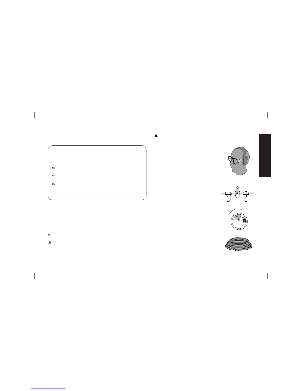
The operator and all those persons in the
general area should wear safety glasses
with permanently attached side shields.
Approved safety glasses are imprinted
with the characters “Z87.1”. It is the
employer’s responsibility to enforce the
use of eye protection equipment by the
tool operator and other people in the work
area. (Fig. A)
• Always wear appropriate personal
hearing and other protection during
use. Under some conditions and duration
of use, noise from this product may
contribute to hearing loss. (Fig. A)
• Use only clean, dry, regulated air.
Conden sation from an air compressor can
rust and damage the internal workings of
the tool. (Fig. B)
• Regulate air pressure. Use air
pressure compatible with ratings on
the nameplate of the tool. (Not to
exceed 120 psi, 8.3 bar) Do not connect
the tool to a compressor rated at over
200 psi. The tool operating pressure must
never exceed 200 psi even in the event of
regulator failure. (Fig. C)
English
1
Page 4
• Only use air hose that is rated for a maximum working
pressure of at least 150 PSI (10.3 BAR) or 150% of the
maximum system pressure, which ever is greater. (Fig. D)
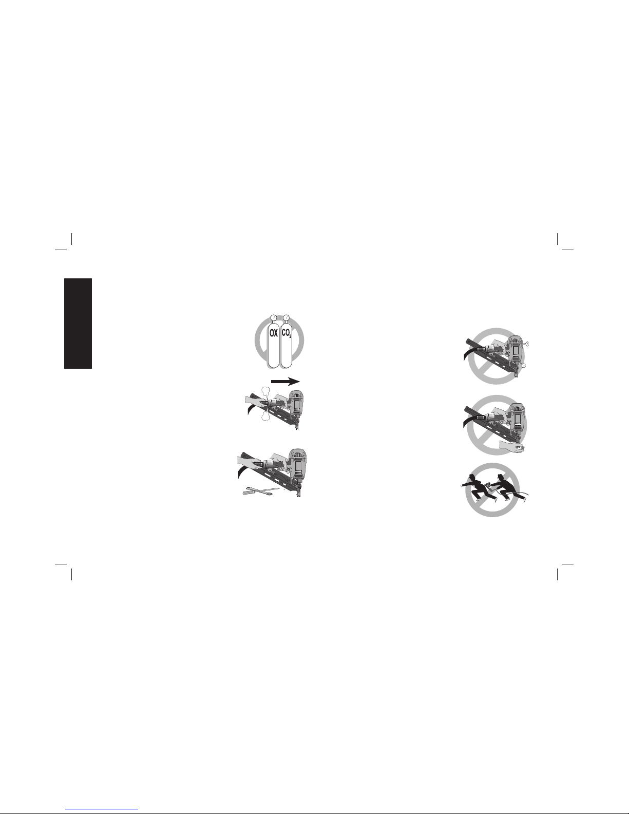
• Do not use bottled gases to power this
FIG. E
FIG. F
FIG. G
tool. Bottled compressed gases such as
oxygen, carbon dioxide, nitrogen, hydrogen,
propane, acetylene or air are not for use
with pneumatic tools. Never use
combustible gases or any other reactive
gas as a power source for this tool. Danger
of explosion and/or serious personal injury
may result. (Fig. E)
• Use couplings that relieve all pressure
from the tool when it is disconnected
from the power supply. Use hose
connectors that shut off air supply from
compressor when the tool is disconnected.
(Fig. F)
• Disconnect tool from air supply when
not in use. Always disconnect tool
from air supply and remove fasteners
from magazine before leaving the
area or passing the tool to another
operator. Do not carry tool to another
work area in which changing location
involves the use of scaffoldings, stairs,
ladders, and the like, with air supply
connected. Do not make adjustments,
remove magazine, perform maintenance or clear jammed
fasteners while connected to the air supply. If the contact trip is
adjusted when the tool is connected to the air supply and nails are
loaded, accidental discharge may occur. (Fig. G)
• Connect tool to air supply before loading fasteners, to
prevent a fastener from being fired during connection. The
tool driving mechanism may cycle when tool is connected to
the air supply. Do not load fasteners with trigger or contact trip
depressed, to prevent unintentional firing of a fastener.
• Do not remove, tamper with, or
FIG. H
FIG. I
FIG. J
otherwise cause the tool, trigger, or
contact trip to become inoperable.
Do not tape or tie trigger or contact trip in
the ON position. Do not remove spring
from contact trip. Make daily inspections
for free movement of trigger and contact
trip. Uncontrolled discharge could result.
• Inspect tool before use. Do not
operate a tool if any portion of the tool,
trigger, or contact trip is inoperable,
disconnected, altered, or not working
properly. Leaking air, damaged parts
or missing parts should be repaired or
replaced before use. (Fig.H)
• Do not alter or modify the tool in any
way. (Fig. I)
• Always assume that the tool contains
fasteners.
• Do not point the tool at co-workers
or yourself at any time. No horseplay!
Work safe! Respect the tool as a working
implement. (Fig. J)
English
2
Page 5
• Keep bystanders, children, and visitors away while operating
a power tool. Distractions can cause you to lose control. When
tool is not in use, it should be locked in a safe place, out of the
reach of children.
• Remove finger from trigger when
not driving fasteners. Never carry
tool with finger on trigger. Accidental
discharge could result. Using the trigger
lock-off will prevent accidental discharge.
• Do not overreach. Maintain proper
footing and balance at all times. Loss of
balance may cause cause personal injury.
(Fig. K)
• Make sure hose is free of obstructions
or snags. Entangled or snarled hoses can
cause loss of balance or footing.
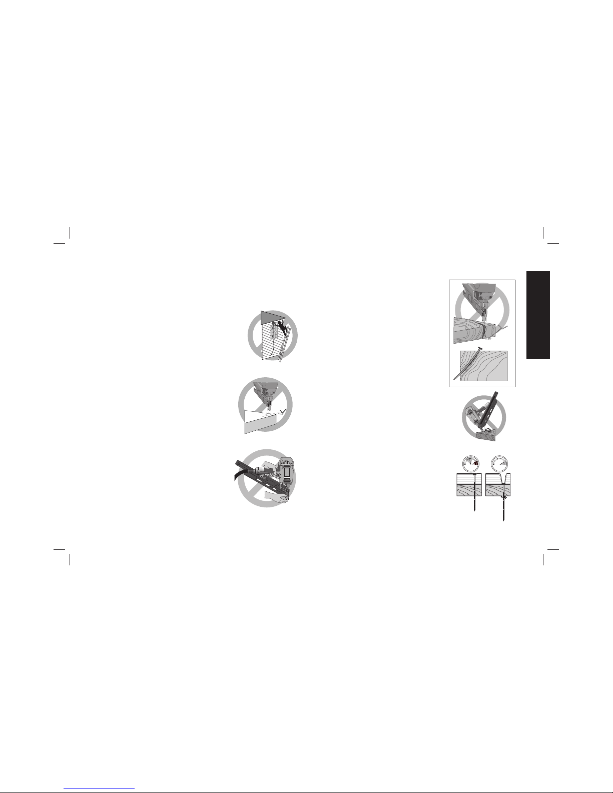
• Use the tool only for its intended use.
Do not discharge fasteners into open
air, concrete, stone, extremely hard
woods, knots or any material too hard
for the fastener to penetrate. Do not
use the body of the tool or top cap as
a hammer. Discharged fasteners may
follow unexpected path and cause injury.
(Fig. L)
• Always keep fingers clear of contact
trip to prevent injury from inadvertent
release of nails. (Fig. M)
• Refer to the Maintenance and Repairs
sections for detailed information on
the proper maintenance of the tool
• Always operate the tool in a clean,
FIG. P
FIG. N
FIG. O
lighted area. Be sure the work surface
is clear of any debris and be careful not
to lose footing when working in elevated
environments such as rooftops.
• Do not drive fasteners near edge
of material. The workpiece may split
causing the fastener to ricochet, injuring
you or a co-worker. Be aware that the nail
may follow the grain of the wood (shiner),
causing it to protrude unexpectedly from
the side of the work material. Drive the
nail perpendicular to the grain to reduce
risk of injury. (Fig. N)
• Do not drive nails onto the heads
of other fasteners or with the tool
at too steep an angle. Personal injury
from strong recoil, jammed fasteners, or
ricocheted nails may result. (Fig. O)
• Be aware of material thickness when
using the nailer. A protruding nail may
cause injury.
• Be aware that when the tool is being
utilized at pressures on the high end
of its operating range, nails can be
driven completely through thin or
very soft work material. Make sure
the pressure in the compressor is set so
that nails are set into the material and not
pushed completely through. (Fig. P)
FIG. K
FIG. L
FIG. M
English
3
Page 6
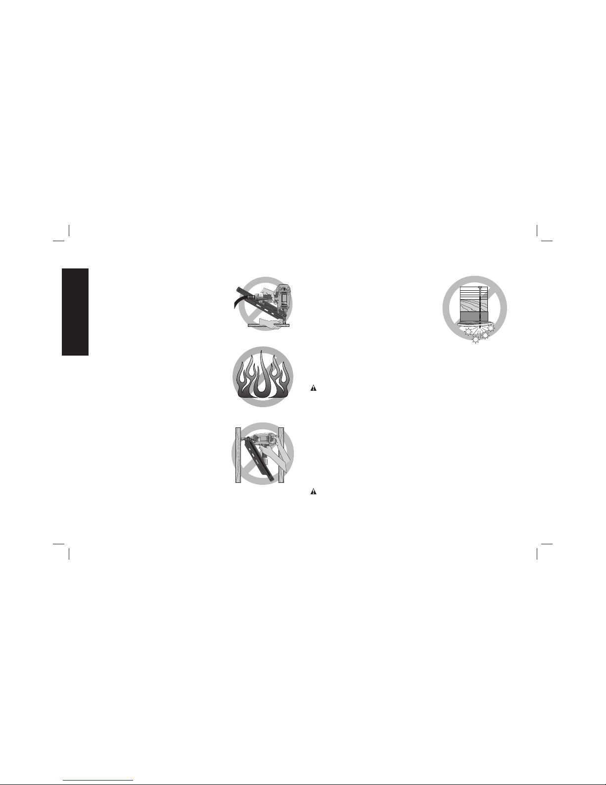
• Keep hands and body parts clear of
FIG. Q
FIG. R
FIG. S
immediate work area. Hold workpiece
with clamps when necessary to keep
hands and body out of potential harm. Be
sure the workpiece is properly secured
before pressing the nailer against the
material. The contact trip may cause the
work material to shift unexpectedly.
(Fig.Q)
• Do not use tool in the presence of
flammable dust, gases or fumes. The
tool may produce a spark that could
ignite gases causing a fire. Driving a nail
into another nail may also cause a spark.
(Fig.R)
• Keep face and body parts away from
back of the tool cap when working
in restricted areas. Sudden recoil can
result in impact to the body, especially
when nailing into hard or dense material.
(Fig. S)
• Grip tool firmly to maintain control
while allowing tool to recoil away
from work surface as fastener is
driven. In “Contact Actuation Mode” if
contact trip is allowed to recontact work
surface before trigger is released an
unwanted fastener will be fired.
• When using the sequential action
FIG. T
trigger, do not actuate the tool
unless the tool is placed firmly
against the workpiece.
• Do not drive nails blindly into walls,
floors or other work areas. Fasteners
driven into live electrical wires, plumbing,
or other types of obstructions can result
in injury. (Fig.T)
• Stay alert, watch what you are
doing and use common sense when
operating a power tool. Do not use tool while tired or under
the influence of drugs, alcohol, or medication. A moment
of inattention while operating power tools may result in serious
personal injury.
WARNING: Some dust created by power sanding, sawing,
grinding, drilling, and other construction activities contains chemicals
known to the State of California to cause cancer, birth defects or other
reproductive harm. Some examples of these chemicals are:
• lead from lead-based paints,
• crystalline silica from bricks and cement and other masonry
products, and
• arsenic and chromium from chemically-treated lumber.
Your risk from these exposures varies, depending on how often you
do this type of work. To reduce your exposure to these chemicals:
work in a well ventilated area, and work with approved safety
equipment, such as those dust masks that are specially designed to
filter out microscopic particles.
WARNING: ALWAYS USE SAFETY GLASSES. Everyday
eyeglasses are NOT safety glasses. Also use face or dust mask
if operation is dusty. ALWAYS WEAR CERTIFIED SAFETY
EQUIPMENT:
English
4
Page 7
• ANSI Z87.1 eye protection (CAN/CSA/Z94.3),
• ANSI S12.6 (S3.19) hearing protection,
• NIOSH/OSHA/MSHA respiratory protection.
SAVE ALL WARNINGS AND INSTRUCTIONS
FOR FUTURE REFERENCE
Tool Specifi cations
MODEL DWMC150
HEIGHT 10-3/4" (274 mm
WIDTH 4-1/4" (108 mm)
LENGTH/ 11-3/4" (296 mm)
WEIGHT/ 4.6 lb (2.1 kg)
MAGAZINE ANGLE 35°
OPERATING PRESSURE
70 – 120 psig (4.9 – 8.43kg/cm2)
AIR CONSUMPTION PER
100 CYCLES *
6.7 cfm @ 80 psi
LOADING CAPACITY
Up to 29 nails
FASTENER LENGTHS 1-1/2" (38 mm)
SHANK DIAMETERS .131"–.148"
(3.33 mm–3.76 mm)
FASTENER COLLATION 35° Paper tape
FASTENER TYPE 35° paper collated full round head
metal connector nails
*Take the actual rate at which the tool will be run to determine the
amount of air required. For instance, if your fastener usage averages
50 nails per minute, you need 50% of the 6.7 cfm (190 liters per
minute) which is required to operate the tool at 100 nails per minute.
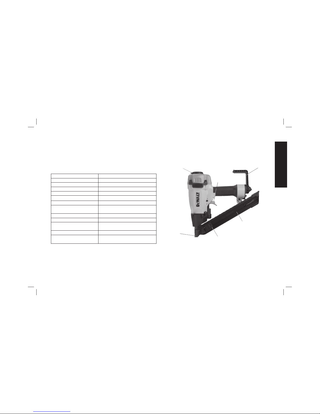
COMPONENTS (FIG. 1)
A. Trigger
B. Exhaust
C. Rafter hook
D. Moveable nose (trip)
E. Pusher
F. Magazine
FIG. 1
E
A
D
C
F
B
English
5
Page 8
OPERATION
Preparing the Tool (Fig. 2, 3)
WARNING: Read the section titled Important Safety Instructions
at the beginning of this manual. Always wear eye and ear protection
when operating this tool. Keep the nailer pointed away from yourself
and others. For safe operation, complete the following procedures
and checks before each use of the nailer.
1. Before you use the nailer, be sure that the compressor tanks
have been properly drained.
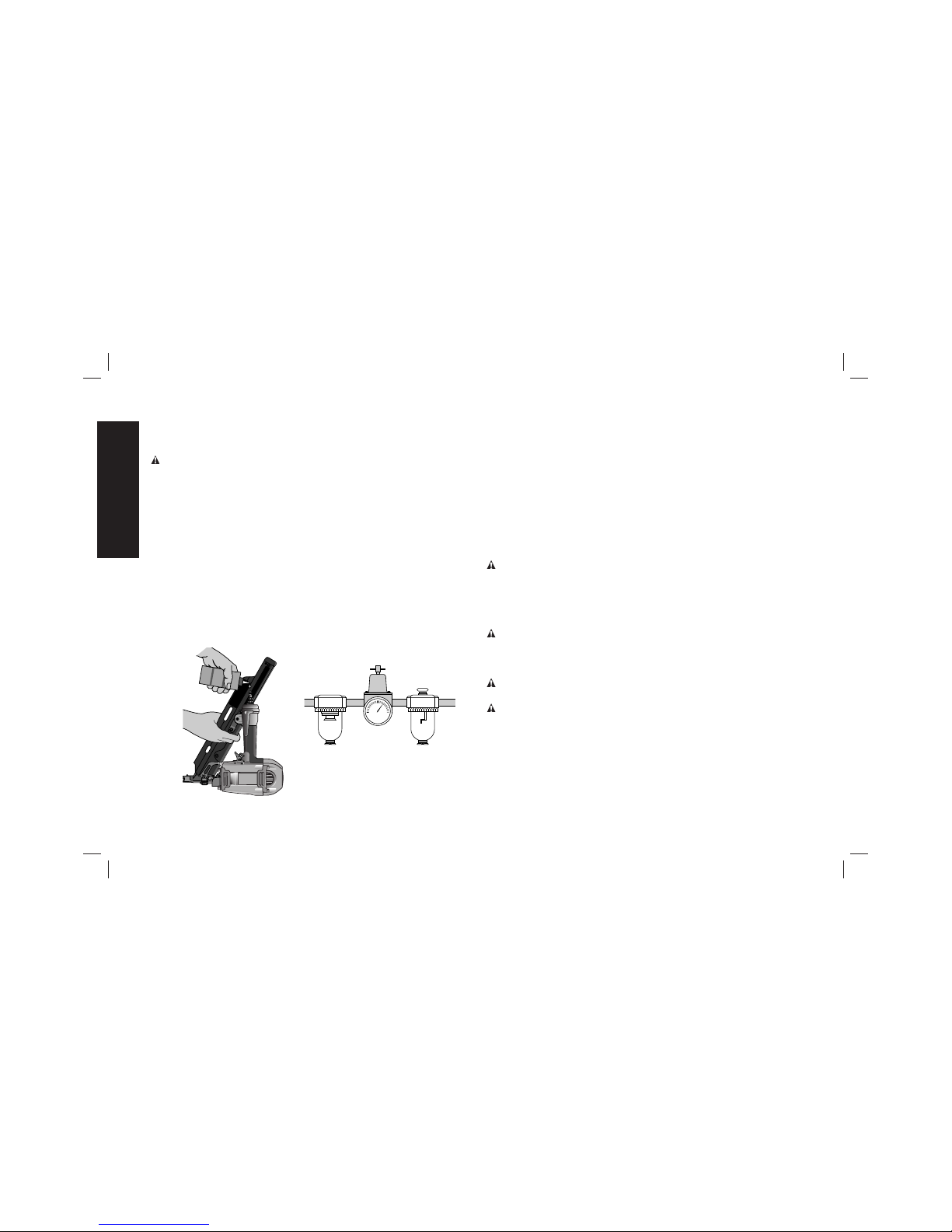
2. Lubricate the tool following these directions:
a. Use D
EWALT pneumatic tool oil or a non-detergent S.A.E. 20
weight oil. DO NOT use detergent oil or additives as they will
damage o-rings and rubber parts.
b. Use a filter-regulator-lubricator in the air line between the
compressor and the tool when possible.
c. If a lubricator is not available, add 5 to 10 drops of oil in the air
fitting a least twice a day or every 4 hours of use.
FIG. 2
FIG. 3
3. Wear proper eye, hearing and respiratory protection.
4. Remove all fasteners from the magazine.
5. Check for smooth and proper operation of contact trip and
pusher assemblies. Do not use tool if either assembly is not
functioning properly. NEVER use a tool that has the contact trip
restrained in the up position.
6. Check air supply. Ensure that air pressure does not exceed
recommended operating limits, refer to Tool Specifications.
7. Connect air hose.
8. Check for audible leaks around valves and gaskets. Never use a
tool that leaks or has damaged parts.
WARNING: To reduce the risk of personal injury, disconnect tool
from air supply before performing maintenance, clearing a jammed
fastener, leaving work area, moving tool to another location or
handing the tool to another person.
Trigger (Fig. 1, 4)
WARNING: The operator must not hold the trigger pulled except
during fastening operation, as serious injury could result if the trip
accidentally contacted someone or something, causing the tool to
cycle.
WARNING: Keep hands and body away from the discharge area
of the tool.
WARNING: Never use rafter hook to hang tool from body, clothing
or belt.
The sequential triggering system gets its name from the “sequence”
required to drive a fastener.
1. Sequential Triggering: offers a positive safety advantage since it
will not accidentally drive a fastener if the tool is bumped against
any surface or anybody while the operator is holding the tools
with the trigger pulled.
English
6
Page 9
2. Sequential Triggering: allows “place nailing” without the
possibility of driving a second, unwanted fastener on recoil.
D
EWALT offers only one mode of operation with this tool.
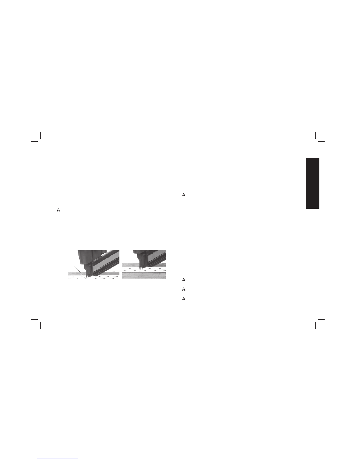
NOTE: This tool operates sequentially, it’s operation is unique from
all other D
EWALT tools. The moveable nose (D), which acts as the
contact trip, is in the “depressed” position at rest to allow visibility of
the nail points used for positive placement. When the tip of the nail is
placed in the preformed metal connector hole (G) and the trigger is
pulled, the moveable nose moves out from the tool to detect the work
surface. If the moveable nose does not detect the work surface close
to the nose of the tool, the tool will not actuate.
WARNING: To avoid serious injury from fasteners and flying debris
when installing metal connectors using the mcn nailer:
• Use only genuine D
EWALT metal connector nails.
• Metal connector nails are not designed to penetrate metal. When
installing metal connectors, always place the exposed point of
the metal connector nail into the metal connector’s pre-formed
hole, and orient so the nail is perpendicular to the hole before
attempting to drive a fastener.
FIG. 4
CORRECT
PLACEMENT OF NAIL
INCORRECT
PLACEMENT OF NAIL
G
TO DRIVE A FASTENER (FIG. 1, 4)
Place the tip of the nail into the metal connectors preformed hole (G),
while holding the moveable nose (the “trip”) FULLY against the work
surface then, pull the trigger (A).
To drive a second nail the operator must lift the tool from the work
surface, release the trigger and then repeat the sequence.
Tool Operation Check (Fig.1)
WARNING: Remove all fasteners from tool before performing tool
operation check.
SEQUENTIAL TRIGGERING OPERATION:
A. Press the moveable nose against the work surface, without
touching the trigger (A).
THE TOOL MUST NOT CYCLE.
B. Hold the tool off the work surface and pull the trigger.
THE TOOL MUST NOT CYCLE.
Release the trigger. The trigger must return to the trigger stop on
the frame.
C. Pull the trigger and press the moveable nose against the work
surface.
THE TOOL MUST NOT CYCLE.
D. With finger off the trigger, press the moveable nose against the
work surface. Pull the trigger.
THE TOOL MUST CYCLE.
Loading the Tool (Fig. 1, 5)
WARNING: Keep tool pointed in a safe direction when loading
nails.
WARNING: Never load nails with the contact trip or trigger
activated.
WARNING: Never mix different length nails in the magazine.
English
7
Page 10
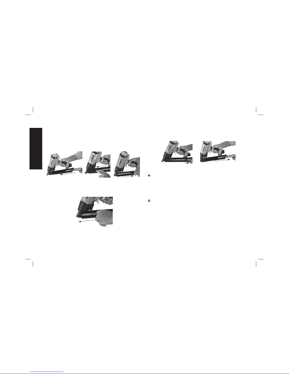
1. Hold nailer with magazine (F) tilted downward and insert
appropriate collated nail sticks into magazine. Refer to Tool
Specifications to determine correct fasteners.
2. Slide nails all the way to the front of magazine.
3. Pull pusher (E) towards rear of magazine past the last nail, then
release to engage pusher to strip of nails.
FIG. 5
TO REMOVE NAILS (FIG. 1, 6, 7)
1. Depress the pusher (E) and slowly slide pusher forward past the
nails to the nosepiece.
FIG. 6
2. Remove nails by releasing the pusher spring and sliding nails
backwards.
3. Depress the pusher (E) and slide nails past magazine tab and
out the magazine.
FIG. 7
Rafter Hook (Fig. 1)
WARNING: Never use rafter hook to hang tool from body, clothing
or belt.
The integrated rafter hook (C) can be rotated to either side of the tool
to accommodate left- or right-handed users.
NOTE: The rafter hook can not be removed.
Cold Weather Operation
WARNING: Read the section titled Important Safety Instructions
at the beginning of this manual. Always wear eye and ear protection
when operating this tool. Keep the nailer pointed away from yourself
and others. For safe operation, complete the following procedures
and checks before each use of the nailer.
When operating tools at temperatures below freezing, complete
preparation procedures outlined above and follow the directions
below.
1. Make sure compressor tanks have been properly drained prior
to use. Always drain the compressor tanks at least once daily
while using the nailer. This is especially important in cold weather
English
8
Page 11

because any moisture in the air in the tanks will condense in the
cold temperature.
2. Keep the tool as warm as possible prior to use.
3. Put 5 to 10 drops of D
EWALT Pneumatic Tool Oil or winter weight
pneumatic oil containing ethylene glycol in the end cap.
4. Lower air pressure to 80 psi or less.
5. Actuate the tool 5 or 6 times into scrap lumber to lubricate o-rings.
6. Turn pressure up to operating level (not to exceed 120 psi) and
use tool as normal.
7. Re-lubricate with D
EWALT Pneumatic Tool Oil or winter weight
pneumatic oil containing ethylene glycol in the end cap at least
twice a day or after 4 hours of use.
Hot Weather Operation
Tool should operate normally. However, keep tool out of direct sunlight
as excessive heat can damage bumpers, o-rings and other rubber
parts.
MAINTENANCE
WARNING: Disconnect air line from tool and remove fasteners
from magazine before making adjustments or personal injury may
result.
Daily Maintenance Chart
ACTION Lubricate tool with 5-10 drops of DEWALT Pneumatic
Tool Oil
WHY Prevents failure of o-rings
HOW Insert drops into air fitting on end cap of tool
ACTION Drain compressor tanks and hoses daily
WHY Prevents accumulation of moisture in compressor and
nailer
HOW Open petcocks or other drain valves on compressor
tanks. Allow any accumulated water to drain from
hoses
ACTION Clean magazine, pusher, and contact trip mechanism
WHY Permits smooth operation, reduces wear, and
prevents jams
HOW Blow clean with compressed air. The use of oils or
solvents is not recommended as they tend to attract
debris
ACTION Before each use, check to ensure all screws, nuts and
fasteners are tight and undamaged
WHY Prevents jams, leaks and premature failure of tool
parts
HOW Tighten loose screws or other fasteners using the
appropriate hex wrench or screwdriver
Cleaning
WARNING: Blow dirt and dust out of all air vents with clean, dry air
at least once a week. To minimize the risk of eye injury, always wear
ANSI Z87.1 approved eye protection when performing this.
WARNING: Never use solvents or other harsh chemicals for
cleaning the non-metallic parts of the tool. These chemicals may
weaken the plastic materials used in these parts. Use a cloth
dampened only with water and mild soap. Never let any liquid get
inside the tool; never immerse any part of the tool into a liquid.
Repairs
WARNING: To reduce the risk of serious personal injury, remove
nails from magazine before making any adjustments or servicing this
tool.
English
9
Page 12

WARNING: Never tamper with or disassemble contact trip (CT)
housing assembly, it can cause severe injury to the user or to
bystanders. Contact trip housing must be replaced as a complete
assembly only.
CAUTION: Pusher spring (constant force spring). Caution must
be used when working with the spring assembly. The spring is
wrapped around, but not attached to, a roller. If the spring is
extended beyond its length, the end will come off the roller and the
spring will roll up with a snap, with a chance of pinching your hand.
Also the edges of the spring are very thin and could cut. Care must
also be taken to insure no permanent kinks are put in the spring as
this will reduce the springs force.
Refer to the Troubleshooting Guide at the end of this section.
To assure product SAFETY and RELIABILITY, repairs, maintenance
and adjustment should be performed by a D
EWALT factory service
center, a D
EWALT authorized service center or other qualified service
personnel. Always use identical replacement parts.
Accessories
WARNING: Since accessories, other than those offered by
D
EWALT, have not been tested with this product, use of such
accessories with this tool could be hazardous. To reduce the risk of
injury, only D
EWALT, recommended accessories should be used with
this product.
Recommended accessories for use with your tool are available
at extra cost from your local dealer or authorized service center.
If you need assistance in locating any accessory, please contact
DEWALT Industrial Tool Co., 701 East Joppa Road, Towson, MD
21286, call 1-800-4-DEWALT (1-800-433-9258) or visit our website
www.dewalt.com.
Register Online
Thank you for your purchase. Register your product now for:
• WARRANTY SERVICE: Registering your product will help you
obtain more efficient warranty service in case there is a problem
with your product.
• CONFIRMATION OF OWNERSHIP: In case of an insurance
loss, such as fire, flood or theft, your registration of ownership will
serve as your proof of purchase.
• FOR YOUR SAFETY: Registering your product will allow us to
contact you in the unlikely event a safety notification is required
under the Consumer Product Safety Act.
Register online at www.dewalt.com/register.
Seven Year Limited Warranty
DEWALT will repair, without charge, any defects due to faulty materials
or workmanship for seven years from the date of purchase. This
warranty does not cover part failure due to normal wear or tool
abuse. For further detail of warranty coverage and warranty repair
information, visit www.dewalt.com or call 1-800-4-D
EWALT (1-800-
433-9258). This warranty does not apply to accessories or damage
caused where repairs have been made or attempted by others. This
warranty gives you specific legal rights and you may have other rights
which vary in certain states or provinces.
In addition to the warranty, D
EWALT tools are covered by our:
1 YEAR FREE SERVICE
D
EWALT will maintain the tool and replace worn parts caused by
normal use, for free, any time during the first year after purchase.
Nailer wear items, such as o-rings and driver blades, are not covered.
English
10
Page 13
90 DAY MONEY BACK GUARANTEE
If you are not completely satisfied with the performance of your
D
EWALT Power Tool, Laser, or Nailer for any reason, you can return
it within 90 days from the date of purchase with a receipt for a full
refund – no questions asked.
LATIN AMERICA: This warranty does not apply to products sold
in Latin America. For products sold in Latin America, see country
specific warranty information contained in the packaging, call the
local company or see website for warranty information.
FREE WARNING LABEL REPLACEMENT: If your warning labels
become illegible or are missing, call 1-800-4-D
EWALT (1-800-433-
9258) for a free replacement.
English
11
Page 14
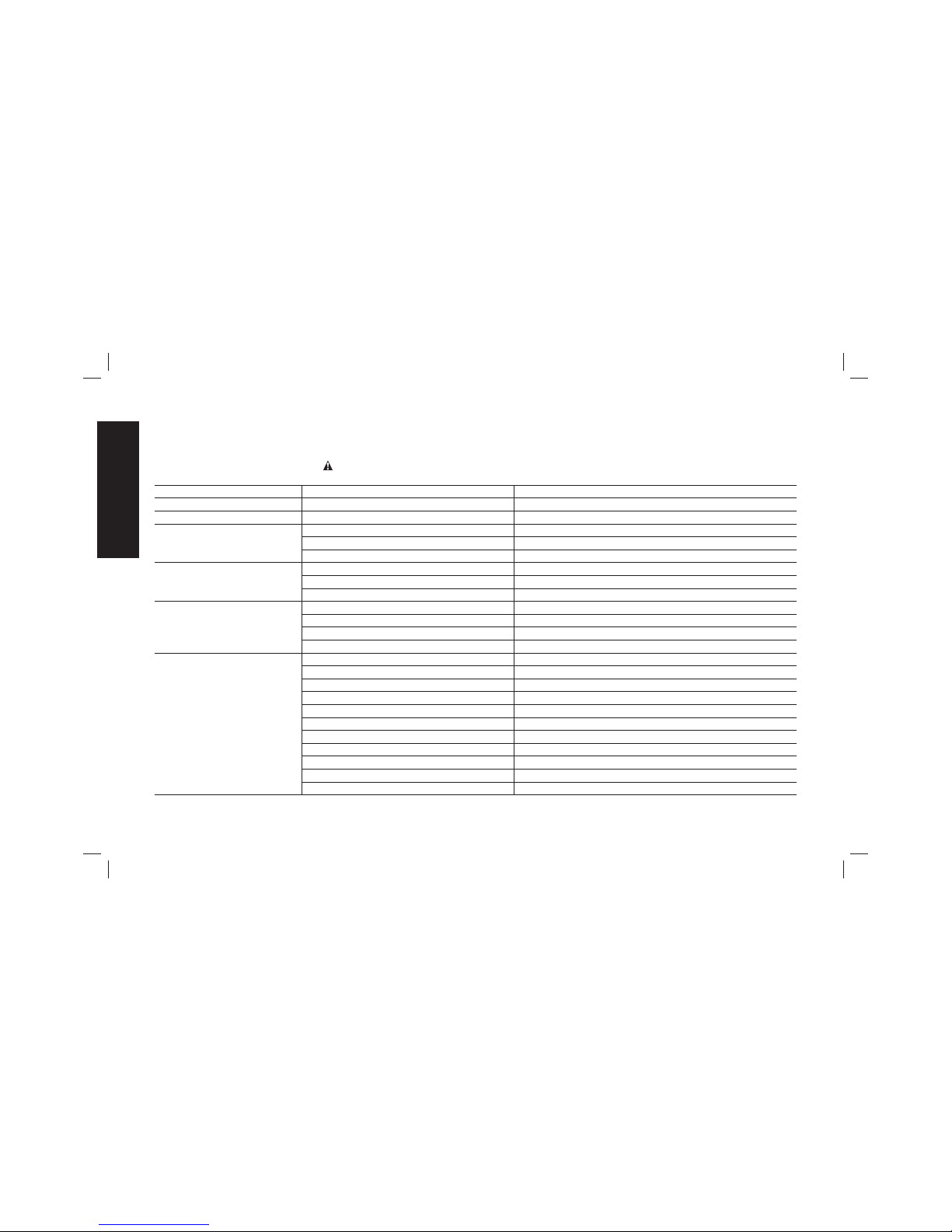
TROUBLESHOOTING GUIDE
MANY COMMON PROBLEMS CAN BE SOLVED EASILY BY UTILIZING THE CHART BELOW.
FOR MORE SERIOUS OR PERSISTENT PROBLEMS, CONTACT A D
EWALT SERVICE CENTER OR CALL 1-(800)-4-DEWALT.
WARNING: To reduce the risk of serious personal injury, remove
fasteners from magazine before making any adjustments or servicing this tool.
SYMPTOM CAUSE FIX
Trigger valve housing leaks air O-ring cut or cracked Replace O-ring
Trigger valve O-ring cut or cracked Replace trigger valve assembly
CT housing leaks air CT housing O-ring cut or cracked Replace CT housing assembly
Shuttle O-ring cut or cracked Replace O-ring
CT housing plate loosened or damaged Replace CT housing assembly
Frame/Nose leaks air Loose nose screws Tighten screws and recheck
O-ring cut or cracked Replace O-ring
Bumper cracked or worn Replace bumper
Frame/Deflector leaks air Damaged gasket Replace gasket
Cracked or worn head valve piston Replace head valve piston
Cracked or damaged sleeve Replace sleeve
Loose deflector screws Tighten screws and recheck
Failure to cycle Air supply restriction Check air supply equipment
Tool dry, lack of lubrication
Lubricate tool using DEWALT pneumatic tool oil
Worn head valve O-rings Replace O-rings
Broken head valve spring Replace head valve spring
Head valve stuck in cap Disassemble/Check/Lubricate
Trigger valve O-ring cut or cracked Replace trigger valve assembly
Wishbone cam pin broken or missing Replace wishbone cam pin
Wishbone cam broken, worn or missing Replace wishbone cam
Cam spring broken or missing Replace cam spring
Cam follower broken or missing Replace cam follower
Moveable nose broken Replace moveable nose
English
12
Page 15
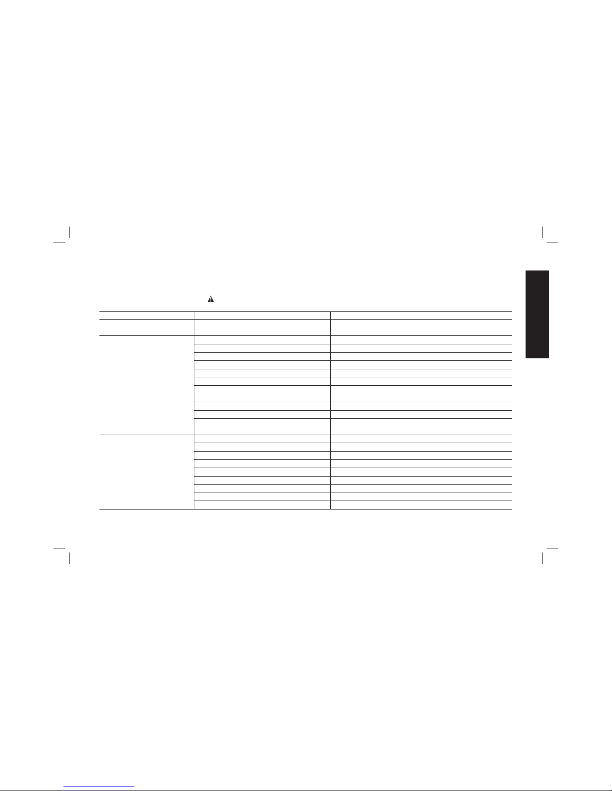
TROUBLESHOOTING GUIDE
MANY COMMON PROBLEMS CAN BE SOLVED EASILY BY UTILIZING THE CHART BELOW.
FOR MORE SERIOUS OR PERSISTENT PROBLEMS, CONTACT A D
EWALT SERVICE CENTER OR CALL 1-(800)-4-DEWALT.
WARNING: To reduce the risk of serious personal injury, remove
fasteners from magazine before making any adjustments or servicing this tool.
SYMPTOM CAUSE FIX
Failure to cycle Moveable nose too far from workpiece Place nail point in metal connector hole/make sure tool is
not tipped so magazine is in contact with work surface
Lack of power; slow to cycle Tool dry, lacks lubrication
Lubricate tool using DEWALT pneumatic tool oil
Broken head valve spring Replace head valve spring
O-rings cut or cracked/gasket damaged Replace O-rings/gasket
Exhaust blocked Check top seal, head valve, deflector cover; replace
Trigger valve worn/leaks Replace trigger valve assembly
Dirt/grime built up on driver Disassemble to remove driver; clean driver
Sleeve not seated correctly on nose Disassemble to correct
Head valve not seated correctly on sleeve Disassemble to correct; replace
Head valve dry Disassemble/lubricate
Air pressure too low Check air supply equipment
Contact arm valve exhaust/port/channel
blocked
Disassemble/Check/Clean; replace assembly
Skipping fasteners; intermittent
feed
Worn magazine Replace magazine
Dry/dirty magazine Clean/lubricate
using DEWALT pneumatic tool oil
Broken/chipped driver Replace driver (check driver piston O-ring)
Trigger valve O-ring cut or cracked Replace trigger valve assembly
Leaking deflector gasket Tighten screws; replace gasket
Wrong sized fasteners Use only recommended fasteners
Bent/damaged fasteners or collation Discontinue using these fasteners
Loose magazine nose screws Tighten all screws
Low air pressure Check air supply system to tool
English
13
Page 16
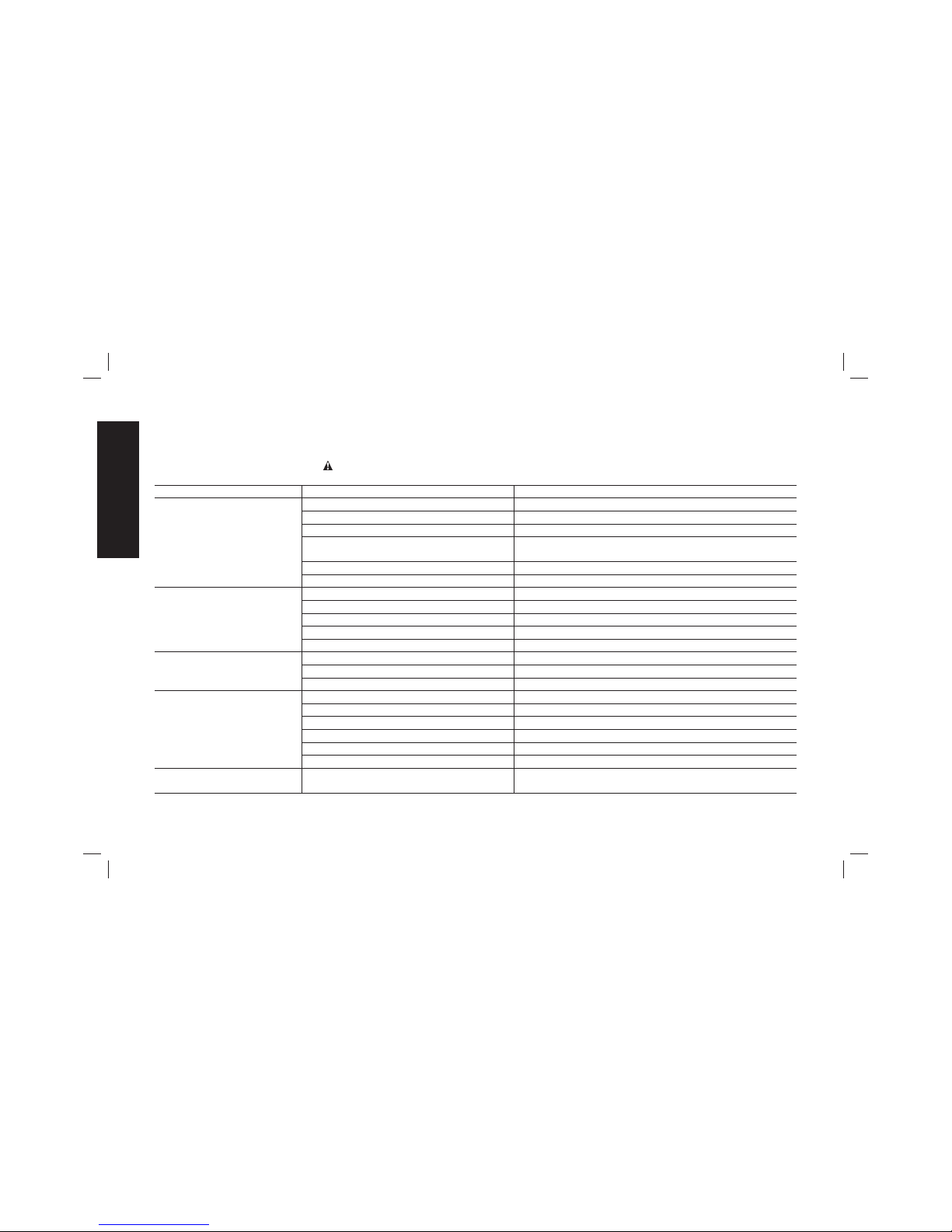
TROUBLESHOOTING GUIDE
MANY COMMON PROBLEMS CAN BE SOLVED EASILY BY UTILIZING THE CHART BELOW.
FOR MORE SERIOUS OR PERSISTENT PROBLEMS, CONTACT A D
EWALT SERVICE CENTER OR CALL 1-(800)-4-DEWALT.
WARNING: To reduce the risk of serious personal injury, remove
fasteners from magazine before making any adjustments or servicing this tool.
SYMPTOM CAUSE FIX
Skipping fasteners; intermittent
feed
Damaged pusher spring Replace spring
Tool dry, lacks lubrication Use
DEWALT pneumatic tool oil
Worn driver piston O-ring Replace O-ring, check driver
Air restriction/inadequate airflow through
socket and plug
Replace quick disconnect fittings
Dirt/grime in driver channel Disassemble and clean driver and sleeve
Worn bumper Replace bumper, check driver and driver piston O-ring
Fasteners jam in tool Driver channel worn Replace Fixed nose
Wrong sized fasteners Use only recommended fasteners
Bent/damaged fasteners or collation Discontinue using these fasteners
Loose magazine/nose screws Tighten all screws
Broken/chipped driver Replace driver
Fastener misses metal
connector hole
Damaged moveable nose Replace moveable nose
Nail not fully positioned in the drive channel Check for debris/collation in drive channel; remove
Hole not properly located with point of nail Place nail point in metal connector hole before firing
Nail point not visible Trigger stem depressed Release trigger; disconnect and reconnect air; replace
Nose spring broken Replace nose spring
Nail jammed in drive channel Disconnect air/clear jam
Cam spring broken or missing Replace cam spring
Cam/shuttle jammed Disconnect air/remove cover/separate cam and
Less than 5 nails/tool in lockout mode Disconnect from air and add new strip of nails
CT housing vibrates, buzzes
or has a delay during actuation
Shuttle O-ring cut or cracked Replace O-ring
English
14
Page 17

AVANT DE FAIRE FONCTIONNER CET OUTIL, LIRE
ATTENTIVEMENT ET COMPRENDRE TOUTES LES DIRECTIVES
DE LA SECTION “CONSIGNES DE SÉCURITÉ IMPORTANTES”
Défi nitions: lignes directrices en
matière de sécurité
Les définitions ci-dessous décrivent le niveau de danger pour
chaque mot-indicateur employé. Lire le mode d’emploi et porter
une attention particulière à ces symboles.
DANGER: indique une situation dangereuse imminente qui,
si elle n’est pas évitée, entraînera la mort ou des blessures
graves.
AVERTISSEMENT : indique une situation potentiellement
dangereuse qui, si elle n’est pas évitée, pourrait entraîner la
mort ou des blessures graves.
ATTENTION : indique une situation potentiellement
dangereuse qui, si elle n’est pas évitée, pourrait entraîner des
blessures légères ou modérées.
AVIS : indique une pratique ne posant aucun risque de
dommages corporels mais qui par contre, si rien n’est fait
pour l’éviter, pourrait poser des risques de dommages
matériels.
POUR TOUTE QUESTION OU REMARQUE AU SUJET DE CET
OUTIL OU DE TOUT AUTRE OUTIL D
E
WALT, COMPOSEZ LE
NUMÉRO SANS FRAIS : 1 800 4-DEWALT (1 800 433-9258)
CONSERVER CES CONSIGNES POUR
UTILISATION ULTÉRIEURE
Directives de sécurité importantes
AVERTISSEMENT: ne pas utiliser cet appareil avant d’avoir lu
le mode d’emploi ainsi que l’intégralité des directives de sécurité,
d’utilisation et d’entretien.
AVERTISSEMENT : ce produit contient
des produits chimiques reconnus par l’État
de la Californie comme étant cancérigènes et
pouvant entraîner des anomalies congénitales
ou d’autres problèmes liés aux fonctions
reproductrices. Se laver les mains après
toute manipulation.
AVERTISSEMENT : certaines poussières
contiennent des produits chimiques reconnus
par l’État de la Californie comme cancérigènes
et pouvant entraîner des anomalies congénitales
et d’autres problèmes liés aux fonctions
reproductrices, te
• La mise en marche de l’outil peut
projeter des débris, du matériel
amalgamé ou de la poussière pouvant
causer des blessures oculaires à
l’opérateur. L’opérateur et toutes les
personnes dans la zone environnante
doivent porter des lunettes de sécurité
avec écrans latéraux fixes. Les lunettes
de sécurité approuvées sont estampillées
avec la mention “Z87.1”. L’employeur a la
responsabilité d’imposer à l’opérateur et à
toutes autres personnes dans la zone de
travail le port d’équipement de protection
des yeux. (fig. A)
FIG. A
FIG. B
FIG. C
FIG. D
Français
15
Page 18

• Toujours porter des protecteurs d’oreilles appropriés et
autres dispositifs de protection durant l’utilisation. Selon les
conditions et la durée d’utilisation, le bruit émis par cet outil peut
causer une perte auditive. (fig. A)
• Utiliser uniquement de l’air propre, sec et régulé. La conden
sation provenant d’un compresseur d’air peut faire rouiller et
endommager les composantes internes de l’outil. (fig. B)
• Réguler la pression d’air. Utiliser une pression compatible
avec la pression nominale indiquée
sur la fiche signalétique de l’outil.
(Ne doit pas excéder 120 psi, 8,3
bars.) Ne pas raccorder l’outil à un
compresseur d’une puissance nominale
supérieure à 200 psi. La pression de
fonctionnement de l’outil ne doit jamais
excéder 200 psi même dans l’éventualité
d’une défaillance du régulateur. (fig. C)
• Utiliser exclusivement un tuyau
d’air prévu pour une pression de
fonctionnement maximale d’au moins
10,3 bars (150 psi) ou 150 % de la
pression maximale du système, selon
la pression la plus élevée. (Fig. D)
• Ne pas utiliser de gaz en bouteille
pour faire fonctionner cet outil. Les
gaz comprimés en bouteille comme
l’oxygène, le bioxyde de carbone, l’azote,
l’hydrogène, le propane, l’acétylène ou
l’air ne doivent pas être utilisés avec les
outils pneumatiques. Ne jamais utiliser
de gaz combustibles ou tout autre type
de gaz réactif comme source d’énergie pour cet outil. Leur
utilisation représente un danger d’explosion et peut se solder par
des blessures corporelles. (fig. E)
• Utiliser des raccords qui libèrent
toute la pression de l’outil lorsqu’il est
débranché de la source d’alimentation.
Utiliser des connecteurs de tuyau
qui coupent l’alimentation d’air du
compresseur quand l’outil est débranché.
(fig. F)
• Débrancher l’outil de la source
d’alimentation en air lorsqu’il n’est
pas utilisé. Toujours débrancher l’outil
de la source d’alimentation en air et
retirer les attaches qui se trouvent
dans le magasin avant de quitter la
zone de travail ou de remettre l’outil à
un autre opérateur. Ne pas transporter
l’outil vers une autre zone de travail
qui comprend des échafaudages, des
marches, des échelles etc., avec la
source d’alimentation en air raccordée.
Ne pas effectuer de réglages, retirer
le magasin, effectuer l’entretien ou
débloquer des attaches coincées
pendant que l’outil est raccordé à
la source d’alimentation en air. Une
décharge accidentelle pourrait se produire
si le déclencheur est réglé alors que l’outil est raccordé à la source
d’alimentation en air et que des clous sont chargés. (fig. G)
•
Brancher l’outil à la source d’alimentation en air avant
de charger les attaches afin de prévenir qu’une attache
FIG. E
FIG. F
FIG. G
FIG. H
FIG. I
FIG. J
Français
16
Page 19

soit éjectée au cours du branchement. Le mécanisme
d’entraînement de l’outil peut être mis en cycle lorsque l’outil est
branché à la source d’alimentation en air. Ne pas enfoncer la
détente ou le déclencheur lors du chargement des attaches pour
prévenir un clouage par inadvertance.
• Ne pas retirer, modifier ou rendre non
FIG. K
FIG. L
FIG. M
fonctionnel, l’outil, la détente ou le
déclencheur de l’outil de quelque
façon que ce soit. Ne pas fixer de ruban
ou d’attache sur la détente ou le
déclencheur pour le maintenir en position
de MARCHE. Ne pas retirer le ressort du
déclencheur. Inspecter quotidiennement
le bon fonctionnement de la détente et du
déclencheur. Une décharge non contrôlée
pourrait survenir.
• Inspecter l’outil avant de l’utiliser. Ne
pas faire fonctionner un outil si une
partie de l’outil, de la détente ou du
déclencheur n’est pas fonctionnelle,
est débranchée, modifiée ou ne
fonctionne pas correctement. Les fuites
d’air ainsi que les pièces endommagées
ou manquantes doivent être réparées ou
remplacées avant utilisation. (fig. H)
• Ne pas transformer ou modifier l’outil
de quelque façon que ce soit. (fig. I)
• Toujours considérer que l’outil contient
des attaches.
• Ne jamais pointer l’outil en direction
d’un collègue de travail ou de soi-
même. Pas de chamaillerie! Toujours travailler prudemment!
Respecter l’outil en tant qu’élément essentiel au travail. (fig. J)
• Tenir les spectateurs, les enfants et les visiteurs à l’écart
durant l’utilisation d’un outil mécanique. Les distractions
peuvent entraîner une perte de maîtrise. Verrouiller l’outil dans un
endroit sûr, hors de la portée des enfants lorsqu’il n’est pas utilisé.
• Enlever le doigt de la détente lorsque vous ne clouez pas. Ne
jamais transporter l’outil avec le doigt sur la détente. Cette
pratique pourrait se solder par une décharge intempestive. Utiliser le
bouton de verrouillage de la détente pour empêcher une décharge
intempestive
• Ne pas tendre le bras trop loin. Il faut demeurer bien campé
sur ses pieds et en équilibre en tout temps. Une perte d’équilibre
risquerait d’entraîner une blessure corporelle. (fig. K)
• S’assurer que le tuyau est exempt d’obstructions ou
d’emmêlements. Des tuyaux entremêlés ou vrillés peuvent faire
perdre l’équilibre ou perdre pied.
• N’utiliser l’outil que pour les travaux pour lesquels il a été
conçu; ne pas décharger les attaches à l’air libre ni dans
des matériaux durs, comme le béton, la pierre, le bois ou les
noeuds ou tout autre matériel trop difficile à pénétrer. Ne pas
utiliser le corps de l’outil ou le couvercle supérieur en guise
de marteau. Les attaches éjectées peuvent suivre une trajectoire
inattendue et causer des blessures. (fig. L)
• Toujours garder les doigts éloignés du déclencheur par
contact afin d’éviter une décharge accidentelle et les
risques de blessure. (fig. M)
• Consulter les sections Entretien et Réparations pour obtenir
les renseignements détaillés sur l’entretien approprié de
l’outil.
Français
17
Page 20

• Toujours utiliser l’outil dans un endroit
FIG. P
FIG. N
FIG. O
propre et bien éclairé; s’assurer que la
surface de travail est exempte de débris et
prendre soin de ne pas perdre l’équilibre
lorsqu’on travaille dans un endroit surélevé,
tel un toit.
• Ne pas enfoncer les attaches près des
bords de la pièce; celle-ci pourrait se
fractionner, ce qui risque de faire ricocher
l’attache et de blesser quelqu’un, y compris
l’utilisateur ou un collègue de travail.
S’assurer de ne pas enfoncer l’attache en
direction du fil du bois afin qu’il ne dépasse
pas le bord de la pièce. Enfoncer le clou
perpendiculaire au fil du bois afin de réduire
les risques de blessure. (fig. N)
• Ne pas enfoncer de clous sur les têtes
d’autres attaches ou à un angle trop
aigu. Cette pratique peut se solder par une
blessure corporelle provoquée par un recul,
un coincement d’attache ou un ricochet de
clou. (fig. O)
• S’informer de l’épaisseur du matériau
lorsque vous utilisez une cloueuse. Un
clou en saillie peut causer des blessures.
• Être conscient que lorsque l’outil est
utilisé à des pressions du côté élevé
de sa gamme de fonctionnement, les
clous peuvent passer complètement
à travers un matériau mince ou très
souple. S’assurer que la pression dans
le compresseur est réglée de sorte que les clous sont fixés dans le
matériau et non poussés entièrement dans celui-ci. (Fig.P)
• Garder les mains et les parties du
FIG. Q
FIG. R
FIG. S
corps éloignées de la zone de travail
immédiate. Au besoin, maintenir la pièce
à travailler avec des serres afin de garder
les mains et les parties du corps éloignées
du danger potentiel. S’assurer que la pièce
à travailler est adéquatement fixée avant de
pousser la cloueuse contre sa surface. Le
déclencheur peut entraîner le déplacement
inopiné de la pièce à travailler. (fig. Q)
• Ne pas utiliser l’outil en présence de
poussières, de gaz ou d’émanations
inflammables. L’outil peut générer une
étincelle qui risque d’enflammer les gaz,
provoquant ainsi un incendie. Une étincelle
peut également survenir si un clou est
enfoncé sur un autre clou. (fig. R)
• Garder le visage et les parties du corps
éloignés de l’arrière du couvercle de
l’outil lorsque le travail est effectué
dans des endroits restreints. Un recul
soudain peut entraîner un impact au corps,
particulièrement durant un clouage dans
des matériaux durs ou denses. (fig. S)
• Saisir l’outil fermement pour
en garder la maîtrise tout en lui
permettant de reculer hors de la
surface de travail lorsque l’attache
est enfoncée. En « mode d’actionnement
Français
18
Page 21

par contact », si le déclencheur retouche la pièce avec la détente
enfoncée, l’outil clouera.
• Lorsqu’on utilise la détente à action séquentielle, ne pas
actionner l’outil à moins qu’il ne soit solidement appuyé sur
la pièce à travailler.
• Ne pas enfoncer de clous à l’aveugle
FIG. T
dans les murs, les planchers ou
autres zones de travail. Des attaches
enfoncées dans des fils électriques sous
tension, de la plomberie ou d’autres
types d’obstacles peuvent entraîner des
blessures. (fig. T)
• Demeurer alerte, prêter attention au
travail à effectuer et faire preuve de
bons sens pendant l’utilisation d’un
outil mécanique. Ne pas utiliser un outil lorsqu’on ressent
de la fatigue ou après avoir consommé des drogues, de
l’alcool ou des médicaments. Un moment d’inattention durant
l’utilisation d’outils mécaniques peut entraîner de graves blessures.
AVERTISSEMENT: les scies, meules, ponceuses, perceuses
ou autres outils de construction peuvent produire des poussières
contenant des produits chimiques reconnus par l’État californien
pour causer cancers, malformations congénitales ou être nocifs au
système reproducteur. Parmi ces produits chimiques, on retrouve :
• le plomb dans les peintures à base de plomb ;
• la silice cristallisée dans les briques et le ciment ou autres
articles de maçonnerie ; et
• l’arsenic et le chrome dans le bois ayant subi un traitement
chimique.
Le risque associé à de telles expositions varie selon la fréquence à
laquelle on effectue ces travaux. Pour réduire toute exposition à ces
produits : travailler dans un endroit bien aéré, en utilisant du matériel
de sécurité homologué tel un masque les microscopiques.
AVERTISSEMENT: TOUJOURS PORTER DES LUNETTES
DE SÉCURITÉ. Les lunettes optiques ne constituent PAS des
lunettes de sécurité. Utiliser également un masque facial
ou anti-poussières si l’opération génère de la poussière.
TOUJOURS PORTER UN ÉQUIPEMENT DE PROTECTION
HOMOLOGUÉ :
• protection oculaire conforme à la norme ANSI Z87.1 (CAN/
CSA Z94.3),
• protection auditive conforme à la norme ANSI S12.6 (S3.19) et
• protection des voies respiratoires conformes aux normes
NIOSH/OSHA/MSHA.
CONSERVER CES CONSIGNES POUR
UTILISATION ULTÉRIEURE
Français
19
Page 22

Fiche technique de l’outil
MODÈLE DWMC150
HAUTEUR 274 mm (10 3/4 po)
LARGEUR 108 mm (4 1/4 po)
LONGUEUR 296 mm (11 3/4 po)
POIDS 2,1kg (4,6lb)
ANGLE DU CHARGEUR 35°
PRESSION DE SERVICE 4,9 à 8,43kg/cm
2
(70 à 120psig)
CONSOMMATION D’AIR
PAR 100 CYCLES*
6,7pi
3
/min à 80psi
CAPACITÉ DU
CHARGEUR
Jusqu’à 29clous
LONGUEUR DES
FIXATIONS
38 mm (1 1/2 po)
DIAMÈTRE DE TIGE 3,33mm à 3,76 mm
(0,131poà 0,148po)
BANDES DE FIXATIONS Bande de papier de 35°
TYPE DE FIXATIONS Clous pour connecteurs métalliques
à tête ronde sur bande de papier
de 35°
*Tenir compte de la vitesse réelle de fonctionnement de l’outil
pour déterminer la quantité d’air nécessaire. Par exemple, si votre
cloueuse utilise environ 50clous à la minute, vous avez besoin de 50
% de 190l/min (6,7pi
3
/min), qui est le volume nécessaire pour faire
fonctionner l'outil à 100clous par minute.
COMPOSANTS (FIG. 1)
A. Gâchette
B. Échappement
C. Crochet à chevron
D. Nez amovible (déclencheur)
E. Poussoir
F. Chargeur
FIG. 1
E
A
D
C
F
B
FONCTIONNEMENT
Préparation de l’outil (Fig. 2, 3)
AVERTISSEMENT: lire la section intitulée Directives de sécurité
importantes début ce manuel. Toujours porter une protection
oculaire et auditive durant l’utilisation de cet outil. Toujours porter
une protection oculaire et une protection auditive lors de l’utilisation
de l’outil. Ne pas pointer la cloueuse dans votre direction ou celle
d’autres personnes. Pour une utilisation sécuritaire, effectuer toutes
les procédures et vérifier tous les points qui suivent avant chaque
utilisation de la cloueuse.
Français
20
Page 23

1. Avant d’utiliser la cloueuse, s’assurer que les réservoirs du
compresseur ont été correctement purgés.
2. Lubrifier l’outil comme suit:
a. Utiliser de l’huile pour outil pneumatique DEWALT ou une huile
S.A.E. de grade 20 non détergente. NE PAS utiliser une huile
détergente ou des additifs pour éviter d’endommager les joints
toriques et les pièces en caoutchouc.
b. Lorsque c’est possible, utiliser un ensemble filtre-régulateur-
lubrificateur avec le tuyau d’air, entre le compresseur et l’outil.
c. Si un lubrificateur n’est pas disponible, ajouter 5 à 10 gouttes
d’huile dans le raccord d’air au moins deux fois par jour ou
après toutes les quatre heures d’utilisation.
FIG. 2
FIG. 3
3. Porter une protection oculaire, auditive et respiratoires adéquates.
4. Retirer toutes les attaches du chargeur.
5. Vérifier le bon fonctionnement régulier du déclencheur et des
ensembles du poussoir. Ne pas utiliser l’outil si un des ensembles
ne fonctionne pas correctement. NE JAMAIS utiliser un outil dont
le déclencheur est coincé en position de marche.
6. Vérifier la source d’alimentation en air. Vérifier que la pression ne
dépasse pas les limites recommandées (se reporter à la fiche
technique de l’outil).
7. Raccorder le tuyau d’air.
8. Vérifier la présence de fuites audibles autour des soupapes et des
joints. Ne jamais utiliser un outil qui présente des fuites ou dont
certaines pièces sont endommagées.
AVERTISSEMENT : pour réduire les risques de blessures
corporelles, débrancher l’outil de la source d’alimentation en air avant
d’effectuer l’entretien, de dégager une attache bloquée, de quitter la
zone de travail, de déplacer l’outil dans un autre endroit ou de donner
l’outil à une autre personne.
Gâchette (fi g. 1, 4)
AVERTISSEMENT: sauf lors du clouage, l’utilisateur ne doit pas
maintenir la gâchette enfoncée, car il existe un risque de blessures
graves si la gâchette entre accidentellement en contact avec une
personne ou un objet et provoque le déclenchement de l’outil.
AVERTISSEMENT : éloigner les mains et le corps de la zone
d'expulsion des clous.
AVERTISSEMENT: ne jamais utiliser un crochet à chevron pour
suspendre l’outil sur le corps, sur un vêtement ou à la ceinture.
Le système de déclenchement séquentiel tire son nom de la
«séquence» nécessaire pour libérer une fixation.
1. Le déclenchement séquentiel : constitue un avantage sur
le plan de la sécurité, puisqu’il interdit tout déclenchement
accidentel si l’outil heurte une surface ou une personne alors que
l’utilisateur appuie sur la gâchette.
2. Le déclenchement séquentiel : permet de « positionner les
clous » tout en évitant qu'une deuxième fixation soit libérée
accidentellement lors du recul.
Français
21
Page 24

DEWALT propose un seul mode de fonctionnement sur cet outil.
REMARQUE: Cet outil fonctionne de manière séquentielle, ce qui
le rend unique parmi les outils de la gamme D
EWALT. Au repos, le
nez amovible (D), qui agit comme déclencheur par contact, reste
en position «enfoncé» afin qu'il soit possible de voir la pointe des
clous, ce qui favorise leur positionnement. Au déclenchement de la
gâchette, lorsque la pointe du clou se trouve dans l'orifice préformé
du connecteur métallique (G), le nez amovible s'écarte de l'outil pour
détecter la surface de travail. S'il ne détecte pas la surface de travail
près du nez de l'outil, ce dernier ne se déclenche pas.
AVERTISSEMENT: pour éviter toute blessure grave causée par
des fixations ou des débris lors de la pose de connecteurs de métal
avec la cloueuse mcn:
• N'utiliser que de véritables clous pour connecteurs métalliques
D
EWALT.
• Les clous pour connecteurs métalliques ne sont pas conçus pour
traverser le métal. Lors de la pose de connecteurs métalliques,
toujours placer la pointe exposée du clou dans le trou préformé
du connecteur, et orienter ce dernier de manière que le clou soit
perpendiculaire au trou.
FIG. 4
CLOU BIEN
POSITIONNÉ
CLOU MAL
POSITIONNÉ
G
LIBÉRATION DE FIXATIONS (FIG. 1, 4)
Placer l’extrémité du clou dans le trou préformé des connecteurs
métalliques (G), tout en appuyant FRANCHEMENT le nez amovible
(le «déclencheur») contre la surface de travail, puis appuyer sur la
gâchette (A).
Pour libérer un deuxième clou, écarter l'outil de la surface de travail,
relâcher la gâchette et répéter la procédure.
Vérifi cation du fonctionnement de l’outil
(fi g.1)
AVERTISSEMENT: toujours retirer toutes les fixations avant de
vérifier le fonctionnement de l’outil.
FONCTIONNEMENT DU DÉCLENCHEMENT SÉQUENTIEL:
A. Appuyer le nez amovible contre la surface de travail sans toucher
à la gâchette(A).
L’OUTIL NE DOIT PAS SE DÉCLENCHER.
B. Tenir l’outil à l’écart de la surface de travail et appuyer sur la
gâchette.
L’OUTIL NE DOIT PAS SE DÉCLENCHER.
Relâcher la gâchette. Elle doit revenir à l’arrêt se trouvant sur le
châssis de l’outil.
C. Appuyer sur la gâchette et presser le nez amovible contre la
surface de travail.
L’OUTIL NE DOIT PAS SE DÉCLENCHER.
D. Sans toucher la gâchette, appuyer le nez amovible contre la
surface de travail. Appuyer sur la gâchette.
L’OUTIL DOIT SE DÉCLENCHER.
Chargement de l’outil (fi g. 1, 5)
AVERTISSEMENT: lors du chargement des clous, toujours diriger
l’outil vers une direction ne présentant aucun danger.
Français
22
Page 25

AVERTISSEMENT : ne jamais charger de clous lorsque le
déclencheur par contact ou la gâchette sont activés.
AVERTISSEMENT: ne jamais mélanger des clous de différentes
longueurs dans le chargeur.
1. Tenir la cloueuse avec le chargeur (F) incliné vers le bas, et insérer
la rame de clous de dimension adaptée dans le chargeur. Pour
savoir quelles fixations utiliser, consulter la fiche technique de
l’outil.
2. Faire glisser les clous jusqu’à l’avant du chargeur.
3. Tirer le poussoir (E) jusque l’arrière du chargeur, après le dernier
clou, puis le relâcher pour qu’il vienne s’appuyer sur la bande de
clous.
FIG. 5
RETRAIT DES CLOUS (FIG. 1, 5, 6)
1. Enfoncer le poussoir (E) et le faire glisser lentement vers l’arrière,
après les clous, en direction de l’embout.
FIG. 6
2. Retirer les clous en libérant le ressort du poussoir et en les faisant
glisser vers l’arrière.
3. Appuyer sur le poussoir (E) et faire glisser les clous au-delà
pour les sortir du chargeur.
FIG. 7
Crochet à chevron (fi g. 1)
AVERTISSEMENT: ne jamais utiliser un crochet à chevron pour
suspendre l’outil sur le corps, sur un vêtement ou à la ceinture.
Il est possible de faire pivoter le crochet à chevron intégré (C) d’un
côté ou de l’autre de l’outil pour une utilisation par un droitier ou par
un gaucher.
REMARQUE : Il est impossible de démonter le crochet à chevron.
Fonctionnement par temps froid
AVERTISSEMENT: lire la section intitulée Directives de sécurité
importantes début ce manuel. Toujours porter une protection
oculaire et auditive durant l’utilisation de cet outil. Garder la cloueuse
pointée en direction opposée de l’opérateur et des autres personnes.
Pour un fonctionnement sécuritaire, effectuer toutes les procédures
et vérifications suivantes avant chaque utilisation de la cloueuse.
Lorsque les outils sont utilisés à des températures inférieures au point
de congélation, effectuer les procédures de préparation ci-dessus et
suivre les directives ci-dessous.
Français
23
Page 26

1. S’assurer que les réservoirs du compresseur ont été purgés
adéquatement avant l’utilisation. Toujours purger les réservoirs
du compresseur au moins une fois par jour durant l’utilisation de
la cloueuse. Ceci est particulièrement important par temps froid
parce que l’humidité dans l’air des réservoirs se condensera.
2. Garder l’outil le plus chaud possible avant l’utilisation.
3. Ajouter dans le capuchon d’extrémité 5 à 10 gouttes d’huile pour
outil pneumatique D
EWALT ou d’huile pneumatique de grade
d’hiver contenant de l’éthylène glycol.
4. Abaisser la pression d’air à 80 psi ou moins.
5. Actionner l’outil à 5 ou 6 reprises dans du bois non utilisable pour
lubrifier les joints toriques.
6.. Augmenter la pression jusqu’au niveau de fonctionnement
(sans excéder 120 psi) et utiliser l’outil normalement.
7. Lubrifier le capuchon d’extrémité de nouveau avec de l’huile pour
outil pneumatique D
EWALT ou de l’huile pneumatique de grade
d’hiver contenant de l’éthylène glycol au moins deux fois par jour
ou toutes les quatre heures d’utilisation.
Fonctionnement par temps chaud
L’outil devrait fonctionner normalement. Cependant, garder l’outil
à l’abri de la lumière directe du soleil étant donné que la chaleur
excessive peut endommager les amortisseurs, les joints toriques et
les autres pièces de caoutchouc.
ENTRETIEN
AVERTISSEMENT : afin d’éviter les risques de blessures,
débrancher le tuyau à air de l’outil et retirer les fixations du chargeur
avant de procéder au réglage.
Tableau d’entretien journalier
ACTION Lubrifier l’outil avec 5 à 10 gouttes d’huile pour outils
pneumatiques DEWALT
POURQUOI Prévenir la défaillance des joints toriques
COMMENT Introduire les gouttes dans le raccord d’air de
l’embout de l’outill
ACTION Vider les réservoirs et les tuyaux du compresseur
quotidiennement
POURQUOI Prévenir l’accumulation d’humidité dans le
compresseur et le clouer
COMMENT Ouvrir les robinets de purge ou les autres robinets
des réservoirs du compresseur
ACTION Nettoyer le magasin, le poussoir et mécanisme du
déclencheur
POURQUOI Permettre un fonctionnement doux, réduire l’usure
et prévenir les blocages
COMMENT Nettoyer à l’air comprimé. L’utilisation d’huiles ou
de solvants n’est pas recommandée car ils ont
tendance à retenir les particules
ACTION Avant chaque utilisation, vérifier si les écrous,vis et
attaches sont serrés et intacts
POURQUOI Prévenir les blocages, les fuites et la défaillance
prématurée des pièces de l’outil
COMMENT Utiliser la clé hexagonale ou le tournevisapproprié(e)
pour serrer les vis ou autres attaches.
Nettoyage
AVERTISSEMENT : enlever les saletés et la poussière hors des
évents au moyen d’air comprimé propre et sec, au moins une fois
par semaine. Pour minimiser le risque de blessure aux yeux, toujours
porter une protection oculaire conforme à la norme ANSI Z87.1 lors
du nettoyage.
Français
24
Page 27

AVERTISSEMENT : ne jamais utiliser de solvants ni d’autres
produits chimiques puissants pour nettoyer les pièces non métalliques
de l’outil. Ces produits chimiques peuvent affaiblir les matériaux
de plastique utilisés dans ces pièces. Utiliser un chiffon humecté
uniquement d’eau et de savon doux. Ne jamais laisser de liquide
pénétrer dans l’outil et n’immerger aucune partie de l’outil dans un
liquide.
Réparations
AVERTISSEMENT : afin d’éviter les risques de blessures,
débrancher le tuyau à air de l’outil et retirer les fixations du chargeur
avant de procéder au réglage.
AVERTISSEMENT : ne jamais modifier ni démonter le boîtier du
déclencheur par contact, sous peine de provoquer des blessures
graves pour l’utilisateur ou les personnes à proximité. Le cas échéant,
le boîtier du déclencheur par contact doit être remplacé dans son
intégralité.
ATTENTION : poussoir à ressort (ressort à force constante). Tout
travail avec le ressort doit s’accompagner de précautions de sécurité.
Le ressort est enroulé autour d’un rouleau auquel il n’est pas fixé.
Lorsqu’il est étiré, son extrémité dépasse le rouleau et il se rétracte
brusquement, ce qui risque de vous pincer la main. Par ailleurs, ses
rebords très fins sont coupants. Il faut également éliminer les
éventuels plis permanents, susceptibles de réduire sa résistance.
Se reporter à la rubrique Guide de dépannage à la fin de cette
section.
Pour assurer la SÉCURITÉ et la FIABILITÉ du produit, les réparations,
l’entretien et les réglages doivent être réalisés par un centre de
réparation en usine D
EWALT, un centre de réparation agréé DEWALT
ou par d’autres techniciens qualifiés. Toujours utiliser des pièces de
rechange identiques.
Accessoires
AVERTISSEMENT : puisque les accessoires autres que ceux
offerts par D
EWALT n’ont pas été testés avec ce produit, leur utilisation
pourrait s’avérer dangereuse. Pour réduire le risque de blessures,
utiliser exclusivement les accessoires D
EWALT recommandés avec
le présent produit.
Les accessoires recommandés pour cet outil sont vendus séparément
au centre de service de votre région. Pour obtenir de l’aide concernant
l’achat d’un accessoire, communiquer avec D
EWALT Industrial Tool
Co., 701 East Joppa Road, Towson, MD 21286 aux États-Unis;
composer le 1 800 433-9258 (1 800 4-D
EWALT) ou visiter notre site
Web : www.dewalt.com.
Registre en ligne
Merci pour votre achat. Enregistrez dès maintenant votre produi:
• RÉPARATIONS SOUS GARANTIE: cette carte remplie vous
permettra de vous prévaloir du service de réparations sous
garantie de façon plus efficace dans le cas d’un probléme avec
le produit.
• CONFIRMATION DE PROPRIÉTÉ: en cas de perte provoquée
par un incendie, une inondation ou un vol, cette preuve de
propriété vous servira de preuve auprès de votre compagnie
d’assurances.
• POUR VOTRE SÉCURITÉ : Enregistrez votre produit. Nous
pourrons ainsi communiquer avec vous dans l’éventualité, peu
probable, où la Consumer Product Safety Act (Loi sur la sécurité
des consommateurs) exige la diffusion d’un avis sur la sécurité.
Registre en ligne à www.dewalt.com/register.
Français
25
Page 28

Garantie à vie limitée de sept (7) ans
DEWALT réparera gratuitement tous les problèmes dus à des défauts
de matériau ou de fabrication pendant sept (7) ans à compter de la
date d’achat. Cette garantie ne couvre pas des défaillances de pièce
dues à une usure normale ou à une mauvaise utilisation de l’outil.
Pour en savoir plus sur la protection et les réparations sous garantie,
visiter le site Web www.dewalt.com ou composer le 1 800 433-9258
(1 800 4-D
EWALT). Cette garantie ne s’applique pas aux accessoires
ni aux dommages causés par des réparations réalisées ou tentées
par des tiers. Cette garantie vous accorde des droits légaux précis et
il est possible que vous ayez d’autres droits qui varient d’un État ou
d’une province à l’autre.
En plus de la garantie, les outils D
EWALT sont couverts par notre:
SERVICE D’ENTRETIEN GRATUIT DE 1 AN
D
EWALT entretiendra l’outil et remplacera les pièces usées par une
utilisation normale et ce, gratuitement, à tout moment pendant la
première année à compter de la date d’achat. L’usure de pièces
comme les joints toriques ou les mécanismes de lames n’est pas
couverte.
GARANTIE DE REMBOURSEMENT DE 90 JOURS
Si vous n’êtes pas entièrement satisfait des performances de votre
outil électrique, laser ou de votre cloueuse D
EWALT pour quelque
raison que ce soit, vous pouvez le renvoyer accompagné d’un reçu
dans les 90 jours suivant la date d’achat, et nous vous rembourserons
entièrement – sans poser de questions.
AMÉRIQUE LATINE : Cette garantie ne s’applique pas aux
produits vendus en Amérique latine. Pour ceux-ci, veuillez consulter
les informations relatives à la garantie spécifique présente dans
l’emballage, appeler l’entreprise locale ou consulter le site Web.
REMPLACEMENT GRATUIT DES ÉTIQUETTES
D’AVERTISSEMENT: Si l’étiquette d’avertissement devient illisible
ou est manquante, composer le 1 800 433-9258 (1 800 4-D
EWALT)
pour un remplacement gratuit.
Français
26
Page 29

GUIDE DE DÉPANNAGE
IL EST POSSIBLE DE RÉSOUDRE FACILEMENT LES PROBLÈMES LES PLUS COMMUNS À L’AIDE DU TABLEAU CI-DESSOUS. POUR
DES PROBLÈMES PLUS GRAVES OU DES PROBLÈMES QUI PERSISTENT, COMMUNIQUER AVEC UN CENTRE DE RÉPARATION
D
EWALT OU COMPOSER LE 1 800 4-DEWALT.
AVERTISSEMENT : pour réduire les risques de blessures graves,
retirer les fixations du chargeur avant de régler, entretenir ou réparer l’outil.
SYMPTÔME CAUSE SOLUTION
Fuite d’air dans le logement de
la valve de gâchette
Joint torique coupé ou fendu Remplacer le joint torique
Valve de gâchette Joint torique coupé ou fendu Remplacer la valve de gâchette
Fuite d’air au logement du
déclencheur par contact
Joint torique du logement du déclencheur par
contact coupé ou fendu
Remplacer le logement du déclencheur par contact
Joint torique de la navette coupé ou fendu Remplacer le joint torique
Plaque du logement du déclencheur par
contact desserrée ou endommagée
Remplacer le logement du déclencheur par contact
Fuite d’air au châssis/nez Vis du nez desserrées Resserrer les vis et refaire une vérification
Joint torique coupé ou fendu Remplacer le joint torique
Butoir fendu ou usé Remplacer le butoir
Fuite d’air au châssis/
déflecteur
Joint d’étanchéité endommagé Remplacer le joint d’étanchéité
Piston de la soupape principale fendu ou
endommagé
Remplacer le piston de la soupape principale
Chemise fendue ou endommagée Remplacer la chemise
Vis du déflecteur desserrées Resserrer les vis et refaire une vérification
Cycle non amorcé Alimentation d’air restreinte Vérifier l’équipement de l’alimentation d’air
Outil sec, manque de lubrifiant
Lubrifier l’outil avec de l’huile pour outils pneumatiques DEWALT
Joints toriques de la soupape principale usés Remplacer les joints toriques
Ressort de soupape principale cassé Remplacer le ressort de soupape principale
Soupape principale coincée dans la tête Démonter, vérifier, lubrifier
Joint torique de la valve de gâchette coupé
ou fendu
Remplacer la valve de gâchette
Français
27
Page 30

GUIDE DE DÉPANNAGE
IL EST POSSIBLE DE RÉSOUDRE FACILEMENT LES PROBLÈMES LES PLUS COMMUNS À L’AIDE DU TABLEAU CI-DESSOUS. POUR
DES PROBLÈMES PLUS GRAVES OU DES PROBLÈMES QUI PERSISTENT, COMMUNIQUER AVEC UN CENTRE DE RÉPARATION
D
EWALT OU COMPOSER LE 1 800 4-DEWALT.
AVERTISSEMENT : pour réduire les risques de blessures graves,
retirer les fixations du chargeur avant de régler, entretenir ou réparer l’outil.
SYMPTÔME CAUSE SOLUTION
Cycle non amorcé
Axe de came oscillante cassé ou fendu Remplacer l’axe de came oscillante
Came oscillante cassée, usée ou fendue Remplacer la came oscillante
Ressort de came cassé ou manquant Remplacer le ressort de came
Galet de came cassé ou manquant Remplacer le galet de came
Nez amovible cassé Remplacer le nez amovible
Nez amovible trop éloigné de la surface de
travail
Placer la pointe du clou dans l’orifice du connecteur
métallique et vérifier que rien ne bouche l’outil de manière
que le chargeur soit en contact avec la surface de travail
Manque de puissance, l’outil
tourne au ralenti
Outil sec, manque de lubrifiant
Lubrifier l’outil avec de l’huile pour outils pneumatiques DEWALT
Ressort de soupape principale cassé Remplacer le ressort de soupape principale
Joints toriques coupés ou fendus/joints
d’étanchéité endommagés
Remplacer les joints toriques/d’étanchéité
Échappement bloqué Vérifier le joint supérieur, la soupape principale, le couvercle
du déflecteur et les remplacer au besoin
Valve de gâchette usée ou qui fuit Remplacer la valve de gâchette
Saleté/crasse accumulées sur l’entraînement Démonter l’entraînement pour le retirer et le nettoyer
Chemise mal posée sur le nez Démonter et corriger
Soupape principale mal posée sur la chemise Démonter et corriger, remplacer
Soupape principale sèche Démonter et lubrifier
Pression d’air trop basse Vérifier l’équipement de l’alimentation d’air
Échappement de la vanne du bras de
contact/port/canal bloqués
Démonter, vérifier, nettoyer; remplacer
Français
28
Page 31

GUIDE DE DÉPANNAGE
IL EST POSSIBLE DE RÉSOUDRE FACILEMENT LES PROBLÈMES LES PLUS COMMUNS À L’AIDE DU TABLEAU CI-DESSOUS. POUR
DES PROBLÈMES PLUS GRAVES OU DES PROBLÈMES QUI PERSISTENT, COMMUNIQUER AVEC UN CENTRE DE RÉPARATION
D
EWALT OU COMPOSER LE 1 800 4-DEWALT.
AVERTISSEMENT : pour réduire les risques de blessures graves,
retirer les fixations du chargeur avant de régler, entretenir ou réparer l’outil.
SYMPTÔME CAUSE SOLUTION
Fixations non utilisées;
alimentation intermittente
Chargeur usé Remplacer le chargeur
Chargeur sale ou sec Nettoyer/lubrifier avec de l’huile pour outils pneumatiques
D
EWALT
Entraînement cassé/abîmé Remplacer l’entraînement (vérifier le joint torique du piston)
Joint torique de la valve de gâchette coupé
ou fendu
Remplacer la valve de gâchette
Fuite au joint d’étanchéité du déflecteur Serrer les vis; remplacer le joint d’étanchéité
Fixations de dimension incorrecte N’utiliser que les fixations recommandées
Bandes ou fixations pliées/endommagées Ne plus utiliser ces fixations
Vis du nez du chargeur desserrées Resserrer toutes les vis
Pression d’air basse Vérifier l’alimentation d’air vers l’outil
Ressort du pousseur endommagé Remplacer le ressort
Outil sec, manque de lubrifiant Utiliser
de l’huile pour outils pneumatiques DEWALT
Joint d’étanchéité de l’entraînement du piston
usé
Remplacer le joint torique, vérifier l’entraînement
Débit d’air limité ou inadapté à travers la
douille et la prise
Remplacer les raccords à dégagement rapide
Saleté/crasse dans le canal d’entraînement Démonter et nettoyer l’entraînement et la chemise
Butoir usé Remplacer le butoir, vérifier l’entraînement et le joint
d’étanchéité du piston
Français
29
Page 32

GUIDE DE DÉPANNAGE
IL EST POSSIBLE DE RÉSOUDRE FACILEMENT LES PROBLÈMES LES PLUS COMMUNS À L’AIDE DU TABLEAU CI-DESSOUS. POUR
DES PROBLÈMES PLUS GRAVES OU DES PROBLÈMES QUI PERSISTENT, COMMUNIQUER AVEC UN CENTRE DE RÉPARATION
D
EWALT OU COMPOSER LE 1 800 4-DEWALT.
AVERTISSEMENT : pour réduire les risques de blessures graves,
retirer les fixations du chargeur avant de régler, entretenir ou réparer l’outil.
SYMPTÔME CAUSE SOLUTION
Fixations coincées dans l’outil Canal d’entraînement usé Remplacer le nez fixe
Fixations de dimension incorrecte N’utiliser que les fixations recommandées
Bandes ou fixations pliées/endommagées Ne plus utiliser ces fixations
Vis du nez/chargeur desserrées Resserrer toutes les vis
Entraînement cassé/abîmé Remplacer l’entraînement
Fixations incapables d’entrer
dans l’orifice du connecteur
métallique
Nez amovible endommagé Remplacer le nez amovible
Clou mal placé dans le canal d’entraînement Chercher la présence de débris/bandes dans le canal
d’entraînement; les retirer
Orifice et pointe du clou mal alignés Placer la pointe du clou dans l’orifice du connecteur
métallique avant d’appuyer sur la gâchette
Pointe de clou non visible Tige de la gâchette enfoncée Relâcher la gâchette; débrancher et rebrancher l’air;
remplacer
Ressort du nez cassé Remplacer le ressort du nez
Clou coincé dans le canal d’entraînement Débrancher l’air, retirer le clou
Ressort de came cassé ou manquant Remplacer le ressort de came
Came/navette coincée Débrancher l’air, retirer le couvercle, débloquer la came
Moins de 5 clous/outil en mode verrouillage Débrancher l’alimentation en air et ajouter des bandes de
clous
Vibrations dans le logement
du déclencheur par contact,
bourdonnement ou retard à
l’activation
Joint torique de la navette coupé ou fendu Remplacer le joint torique
Français
30
Page 33

ANTES DE OPERAR ESTA HERRAMIENTA LEA CON
DETENIMIENTO LAS INSTRUCCIONES DEL APARTADO
“INSTRUCCIONES IMPORTANTES DE SEGURIDAD”.
Defi niciones: Normas de seguridad
Las siguientes definiciones describen el nivel de gravedad de
cada palabra de señal. Lea el manual y preste atención a estos
símbolos.
PELIGRO: Indica una situación de peligro inminente que, si no
se evita, provocará la muerte o lesiones graves.
ADVERTENCIA: Indica una situación de peligro potencial que,
si no se evita, podría provocar la muerte o lesiones graves.
ATENCIÓN: Indica una situación de peligro potencial que,
si no se evita, posiblemente provocaría lesiones leves o
moderadas.
AVISO: Se refiere a una práctica no relacionada a lesiones
corporales que de no evitarse puede resultar en daños a la
propiedad.
SI TIENE ALGUNA PREGUNTA O DESEA HACER ALGÚN COMENTARIO
SOBRE ESTA O CUALQUIER OTRA HERRAMIENTA DEWALT, LLAME
SIN COSTO AL: 1-800-4-DEWALT (1-800-433-9258)
GUARDE ESTAS INSTRUCCIONES
PARA FUTURAS CONSULTASOUR
UTILISATION ULTÉRIEURE
Instrucciones de seguridad importantes
ADVERTENCIA: No opere esta unidad hasta que haya leído este
manual de instrucciones de seguridad, operación y mantenimiento.
ADVERTENCIA: Este producto contiene
sustancias químicas,incluido el plomo,
reconocidas por el Estado de California como
causantes de cáncer, defectos de nacimiento
u otros problemas reproductivos. Lávese las
manos después de utilizarlo.
ADVERTENCIA: Algunos tipos de polvo
contienen sustancias químicas, como
el amianto y el plomo de las pinturas de
base plomo, reconocidas por el Estado
de California como causantes de cáncer,
defectos de nacimiento u otros problemas.
• El funcionamiento de la herramienta
puede despedir residuos, material de
colación o polvo, que podrían dañar
los ojos del operador. El operador y
todas las personas cercanas deben llevar
lentes de seguridad con protectores
laterales permanentes. Los lentes de
seguridad certificados se distinguen
por los caracteres impresos “Z87.1”. Es
responsabilidad del empleador asegurarse
de que tanto el operador de la herramienta
como las personas situadas en el área
de trabajo utilicen equipos de protección
ocular. (Fig. A)
• Utilice siempre la apropiada protección,
tanto auditiva como de otro tipo,
durante la utilización. En determinadas
condiciones y con utilizaciones prolongadas, el ruido generado por
este producto puede contribuir a la pérdida de audición. (Fig. A)
FIG. A
FIG. B
FIG. C
FIG. D
Español
31
Page 34

• Utilice solamente aire limpio, seco y
regulado. La condensación debida al
compresor de aire puede oxidar y dañar
las piezas internas de la herramienta.
(Fig.B)
• Regule la presión del aire. Utilice
una presión compatible con los
valores indicados en la placa de
características. (No debe exceder
de 120 psi, 8.3 bar.) No conecte la
herramienta a un compresor con un
valor superior a 200 psi. La presión de
funcionamiento de la herramienta no debe
exceder nunca los 200 psi, incluso en el
caso de que falle el regulador. (Fig.C)
• Utilice únicamente una manguera de
aire que tenga una capacidad nominal
para una presión de trabajo máxima
de 10,3 BAR (150 PSI), como mínimo,
o el 150% de la presión máxima del
sistema, el valor que sea mayor. (Fig.D)
• No utilice gas embotellado
para suministrar energía a esta
herramienta. Los gases comprimidos y
embotellados, como el oxígeno, el dióxido
de carbono, el nitrógeno, el hidrógeno, el propano, el acetileno o
el aire no se deben usar para las herramientas neumáticas. Nunca
utilice gases combustibles o cualquier otro gas reactivo como fuente
de energía para esta herramienta. Podría provocarse un peligro de
explosión y/o lesiones personales graves. (Fig. E)
• Utilice conexiones que alivien toda la presión de la herramienta
cuando se desconecte de la toma de corriente. Utilice
conectores de mangueras que bloqueen
el suministro de aire del compresor
cuando la herramienta se desconecte.
(Fig. F)
• Desconecte la herramienta del
suministro de aire cuando no se
vaya a usar. Siempre desconecte la
herramienta del suministro de aire y
retire los clavos del cargador antes de
dejar la zona de trabajo o de pasar la
herramienta a otro operador. No lleve
la herramienta a otra área de trabajo
en la que el cambio de ubicación
involucre el uso de andamios,
escalones, escaleras, etc., con el
suministro de aire conectado. No
realice ajustes ni extraiga el cargador
ni realice labores de mantenimiento
o desatascado de la herramienta con
el suministro de aire conectado. Si
se ajusta el activador por contacto con
la herramienta conectada al suministro
de aire y los clavos cargados, puede
producirse una descarga accidental.
(Fig.G)
• Conecte la herramienta al suministro de aire antes de cargar
los elementos de fijación, para evitar que uno de ellos
se dispare durante la conexión. El mecanismo impulsor de
la herramienta puede presentar ciclos cuando se conecta la
herramienta al suministro de aire. No cargue elementos de fijación
si el disparador o el activador por contacto están presionados, para
evitar el disparado intencional.
FIG. E
FIG. F
FIG. G
FIG. H
FIG. I
FIG. J
Español
32
Page 35

• No extraiga, altere, ni provoque el cese
FIG. K
FIG. L
FIG. M
del funcionamiento de la herramienta,
el gatillo o el activador por contacto.
No ate ni fije con cinta adhesiva el gatillo ni
el activador por contacto en la posición de
ENCENDIDO. No extraiga el resorte del
activador por contacto. Inspeccione
diariamente para ver si el disparador y el
activador por contacto se mueven
libremente. Se puede producir una
descarga incontrolada.
• Revise la herramienta antes de usarla.
No trabaje con la herramienta si
alguna parte de ésta, el gatillo o el
activador por contacto no funcionan;
o si está desconectada o modificada o
no funciona adecuadamente. Las fugas
de aire y las piezas dañadas o que falten
se deben reparar o reemplazar antes de la
utilización. (Fig. H)
• No modifique ni cambie nunca la
herramienta. (Fig. I)
• Siempre tenga en cuenta que la
herramienta contiene clavos.
• No apunte en ningún momento con
la herramienta a ningún compañero
ni a usted mismo. No juegue con la
herramienta. Trabaje con seguridad. Considere que la herramienta
es un utensilio de trabajo. (Fig. J)
• Mientras opere una herramienta eléctrica, mantenga lejos a
los observadores, niños y visitantes. Las distracciones pueden
ocasionar que pierda el control. Cuando la herramienta no esté en
uso, se debe guardarla en un lugar seguro, fuera del alcance de los
niños.
• Quite el dedo del disparador cuando no esté colocando
elementos de fijación. Nunca transporte la herramienta con
el dedo en el disparador. Podría producirse una descarga
accidental. El uso del bloqueo del disparador evitará la descarga
accidental.
• No ponga en peligro su estabilidad. Manténgase siempre bien
apoyado y equilibrado. La pérdida del equilibrio podría provocar una
lesión personal. (Fig. K)
• La manguera debe estar libre de obstrucciones o enganches.
Las mangueras enredadas o enmarañadas pueden provocar una
pérdida de equilibrio o una falta de apoyo.
• Use la herramienta sólo para lo que fue diseñada. No
descargue grapas al aire, en concreto, piedra, maderas muy
duras, nudos o cualquier otro material que sea demasiado
duro para que la grapa lo penetre. No utilice la herramienta ni
la tapa superior como martillo. Las grapas descargadas podrían
seguir trayectorias inesperadas y causar lesiones. (Fig. L)
• Mantenga siempre los dedos alejados del activador por
contacto para evitar lesiones por la descarga inadvertida de
clavos. (Fig. M)
• Consulte los apartados de Mantenimiento y Reparaciones
para obtener más información sobre el mantenimiento
adecuado de la herramienta.
• Opere siempre la herramienta en un área limpia e iluminada.
Asegúrese de que la superficie de trabajo esté limpia de todo
desecho y tenga cuidado de no perder el equilibrio cuando trabaje
en entornos elevados como tejados.
Español
33
Page 36

• No intente insertar grapas cerca del
FIG. P
FIG. N
FIG. O
borde del material. La pieza de trabajo
podría quebrarse y hacer que la grapa
rebotase, lesionándolo a usted o a un
compañero. Observe también que la
grapa puede insertarse siguiendo la
dirección de la veta de la madera,
haciendo que sobresalga
inesperadamente de un lado del material
de trabajo. Inserte el clavo perpendicular
al grano de la madera para reducir el
riesgo de lesiones. (Fig. N)
• No coloque clavos en las cabezas
de otros elementos de fijación o
con la herramienta en un ángulo
demasiado pronunciado. Podría
producirse una lesión personal a causa
de un fuerte retroceso, el atascamiento
de los elementos de fijación o el rebote
de los clavos. (Fig. O)
• Conozca el espesor del material
cuando utilice la clavadora. Un clavo
que sobresale puede provocar una lesión.
• Tenga en cuenta que cuando se
utiliza la herramienta a presiones
del extremo superior del margen
de operación, los clavos pueden
atravesar completamente los
materiales delgados o muy blandos.
Asegúrese de que la presión del
compresor esté definida para que
los clavos se introduzcan en el material y no lo traspasen
completamente. (Fig.P)
• Mantenga las manos y otras partes
FIG. Q
FIG. R
FIG. S
del cuerpo alejadas del área de
trabajo más inmediata. Sostenga la
pieza con abrazaderas cuando sea
necesario, para mantener las manos y el
cuerpo alejados de la zona de peligro. La
pieza debe estar adecuadamente sujeta
antes de presionar la clavadora contra el
material. El activador por contacto puede
provocar que el material de trabajo se
mueva inesperadamente. (Fig. Q)
• No utilice la herramienta en presencia
de polvo, gases o humos inflamables.
La herramienta puede producir chispas
que podrían encender los gases y
provocar un incendio. Si clava un clavo
encima de otro se pueden producir
chispas. (Fig. R)
• Mantenga la cara y otras partes del
cuerpo lejos de la parte posterior
de la tapa de la herramienta cuando
trabaje en espacios limitados. El
retroceso repentino puede provocar
impactos en el cuerpo, especialmente
cuando clave en materiales duros o
compactos. (Fig. S).
• Agarre la herramienta con firmeza
para mantener el control pero
permita que la herramienta retroceda
Español
34
Page 37

de la superficie de trabajo cuando se clava el elemento
de fijación. En el “Modo accionamiento por contacto” si se
permite que el activador por contacto vuelva a tocar la superficie
de trabajo antes de que se suelte el disparador, se disparará un
elemento de fijación innecesario.
• Cuando utilice el gatillo secuencial no opere la herramienta
a menos que esté firmemente colocada contra la pieza.
• No clave indiscriminadamente en
FIG. T
paredes, suelos u otras superficies
de trabajo. Los clavos introducidos en
cables eléctricos, cañerías u otro tipo de
obstrucciones pueden provocar lesiones.
(Fig. T)
• Al utilizar una herramienta eléctrica,
esté atento, concéntrese en lo que
hace y aplique el sentido común. No
utilice la herramienta si se encuentra
fatigado o bajo la influencia de
drogas, alcohol o fármacos. Mientras se utilizan herramientas
eléctricas, basta un instante de distracción para sufrir lesiones
graves.
ADVERTENCIA: Algunas partículas de polvo generadas al lijar,
serrar, esmerilar y taladrar con herramientas eléctricas, así como al
realizar otras actividades de construcción, contienen químicos que
el Estado de California sabe que pueden producir cáncer, defectos
congénitos u otras afecciones reproductivas. Ejemplos de estos
químicos son:
• plomo de algunas pinturas,
• polvo de sílice proveniente de ladrillos y cemento y otros
productos de albañilería, y
• Arsénico y cromo proveniente de madera tratada químicamente.
El peligro derivado de la exposición a estos materiales varía en
función de la frecuencia con que se realice este tipo de trabajo.
Para reducir su exposición a estos químicos: trabaje en una zona
bien ventilada y llevando equipos de seguridad aprobados, como
mascarillas antipolvo especialmente diseñadas para filtrar partículas
microscópicas.
ADVERTENCIA: USE SIEMPRE LENTES DE SEGURIDAD.
Los anteojos de uso diario NO son lentes de seguridad.
Utilice también máscaras faciales o para polvo si la operación
produce polvillo. UTILICE SIEMPRE EQUIPOS DE SEGURIDAD
CERTIFICADOS:
• Protección para los ojos ANSI Z87.1(CAN/CSA Z94.3),
• protección auditiva ANSI S12.6 (S3.19),
• Protección respiratoria según las normas NIOSH/OSHA/MSHA.
GUARDE ESTAS INSTRUCCIONES
PARA FUTURAS CONSULTASOUR
UTILISATION ULTÉRIEURE
Español
35
Page 38

Especifi caciones de la herramienta
MODELO DWMC150
ALTURA 274 mm (10-3/4")
ANCHO 108 mm (4-1/4")
LARGO 296 mm (11-3/4")
PESO 2,1 kg (4,6 lb)
ÁNGULO DEL CARGADOR 35°
PRESIÓN DE
FUNCIONAMIENTO
4,9 - 8,43kg/cm
2
(70 - 120 psig)
CONSUMO DE AIRE
CADA 100 CICLOS *
6,7 cfm a 80 psi
CAPACIDAD DE CARGA Hasta 29 clavos
LONGITUD DE LOS
REMACHES
38 mm (1-1/2")
DIÁMETRO DEL VÁSTAGO 3,33 mm - 3,76 mm
(0,131" - 0,148")
UNIÓN DE LOS
REMACHES
Cinta de papel a 35°
TIPO DE REMACHE Clavos conectores de metal con
cabeza redonda unidos con papel
a 35°
*Tome la tasa real en que la herramienta funcionará para determinar
la cantidad de aire necesario. Por ejemplo, si su uso de remaches
alcanza un promedio de 50 clavos por minuto, necesita un 50 %
de los 6,7 cfm (190 litros por minuto) requeridos para utilizar la
herramienta a 100 clavos por minuto.
COMPONENTES (FIG. 1)
A. Gatillo
B. Escape
C. Gancho transversal
D. Nariz móvil (interruptor)
E. Impulsor
F. Cargador
FIG. 1
E
A
D
C
F
B
FUNCIONAMIENTO
Preparación de la herramienta (Fig. 2, 3)
ADVERTENCIA: Lea la sección titulada Instrucciones de
seguridad importantes al principio de este manual. Siempre use
protección adecuada para ojos y oídos cuando use la herramienta.
Español
36
Page 39

No dirija la herramienta hacia usted o hacia otras personas. Para
una utilización segura, lleve adelante los siguientes procedimientos y
controles cada vez que vaya a usar la clavadora.
1. Antes de usar la herramienta, asegúrese de que los tanques del
compresor se hayan vaciado adecuadamente.
2. Lubrique la herramienta siguiendo estas instrucciones:
a. Utilice aceite DEWALT para herramientas neumáticas o un
aceite no detergente de peso 20 S.A.E. NO utilice aceite
detergente o aditivos, ya que se dañarán las juntas tóricas y
las piezas de goma.
b. Utilice un filtro-regulador-lubricador en la línea de aire entre el
compresor y la herramienta siempre que sea posible.
c. Si no hay un lubricador disponible, coloque de 5 a 10 gotas de
aceite en el accesorio de aire dos veces al día como mínimo o
cada 4 horas de uso.
FIG. 2
FIG. 3
3. Use protección ocular, auditiva y respiratoria adecuada.
4. Extraiga todos los elementos de fijación del depósito.
5. Verifique que el activador por contacto y los conjuntos del
impulsador funcionen fácil y correctamente. No use la herramienta
si algún conjunto no funciona adecuadamente. NUNCA use una
herramienta que tenga el activador por contacto restringido en la
posición hacia arriba.
6. Controle el suministro de aire. Verifique que la presión de aire no
supere los límites recomendados de funcionamiento; consulte
Especificaciones de la herramienta.
7. Conecte la manguera de aire.
8. Controle si hay pérdidas audibles alrededor de válvulas y sellos.
Nunca utilice una herramienta que tenga pérdidas o piezas
dañadas
ADVERTENCIA: Para reducir el riesgo de lesiones personales,
desconecte la herramienta del suministro de aire antes de realizarle
mantenimiento, extraer un elemento de fijación atascado, dejar el
área de trabajo, mover la herramienta a otra ubicación o alcanzarle la
herramienta a otra persona.
Gatillo (Fig. 1, 4)
ADVERTENCIA: El operador no debe mantener el gatillo apretado,
excepto durante la tarea de ajuste, ya que podrían producirse
lesiones graves si el interruptor accidentalmente hiciera contacto con
un objeto o una persona, provocando que la herramienta se accione.
ADVERTENCIA: Mantenga las manos y el cuerpo alejados del
área de descarga de la herramienta.
ADVERTENCIA: Nunca use el gancho transversal para colgar la
herramienta del cuerpo, la indumentaria o el cinturón.
El sistema de gatillo secuencial obtiene su nombre de la “secuencia”
requerida para aplicar un remache.
Español
37
Page 40

1. Interruptor secuencial: ofrece una ventaja de seguridad positiva
ya que no aplicará accidentalmente un remache si la herramienta
toca una superficie o una persona mientras el operador sostiene
las herramientas con el gatillo presionado.
2. Interruptor secuencial: permite el “clavado en el lugar” sin la
posibilidad de aplicar un segundo remache no deseado en el
rebote.
D
EWALT ofrece solo un modo de funcionamiento con esta herramienta.
NOTA: Esta herramienta funciona secuencialmente. Su funcionamiento
es diferente al de todas las demás herramientas D
EWALT. La nariz
móvil (D) que actúa como interruptor de contacto está en posición
“presionada” en reposo para permitir la visibilidad de las puntas de los
clavos usados para la colocación positiva. Cuando la punta del clavo
se coloca en el orificio del conector de metal preformado (G) y se
presiona el gatillo, la nariz móvil sale de la herramienta para detectar
la superficie de trabajo. Si la nariz móvil no detecta la superficie de
trabajo cerca de la nariz de la herramienta, la herramienta no se
accionará.
ADVERTENCIA: Para evitar lesiones graves con los remaches y
los desechos que salgan volando al instalar los conectores de metal
usando la clavadora mcn:
• Use solo clavos conectores de metal D
EWALT originales.
• Los clavos conectores de metal no están diseñados para penetrar
metal. Al instalar conectores de metal, siempre coloque la punta
expuesta del clavo conector de metal en el orificio preformado
del conector de metal y oriéntelo de forma tal que el clavo quede
perpendicular al orificio antes de intentar colocar un remache.
FIG. 4
COLOCACIÓN
CORRECTA DEL
CLAVO
COLOCACIÓN
INCORRECTA DEL CLAVO
G
PARA COLOCAR UN REMACHE (FIG. 1, 4)
Coloque la punta del clavo en el orificio preformado para conectores
de metal (G), al tiempo que sostiene la nariz móvil (el “interruptor”)
TOTALMENTE contra la superficie de trabajo; luego presione el
gatillo(A).
Para aplicar un segundo clavo, el operador debe levantar la
herramienta de la superficie de trabajo, liberar el gatillo y luego repetir
la secuencia.
Comprobación de funcionamiento de la
herramienta (Fig. 1)
ADVERTENCIA: Quite todos los remaches de la herramienta
antes de realizar la comprobación de funcionamiento de esta.
FUNCIONAMIENTO DEL INTERRUPTOR SECUENCIAL:
A. Presione la nariz móvil contra la superficie de trabajo, sin tocar el
gatillo (A).
LA HERRAMIENTA NO DEBE ACCIONARSE.
B. Sostenga la herramienta sin apoyar sobre la superficie de trabajo
y presione el gatillo.
LA HERRAMIENTA NO DEBE ACCIONARSE.
Español
38
Page 41

Libere el gatillo. El gatillo debe volver a la posición de detención
del gatillo en el marco.
C. Presione el gatillo y presione la nariz móvil contra la superficie de
trabajo.
LA HERRAMIENTA NO DEBE ACCIONARSE.
D. Con el dedo fuera del gatillo, presione la nariz móvil contra la
superficie de trabajo. Presione el gatillo.
LA HERRAMIENTA DEBE ACCIONARSE.
Carga de la herramienta (Fig. 1, 5)
ADVERTENCIA: Mantenga la herramienta apuntando a una
dirección segura al cargar los clavos.
ADVERTENCIA: Nunca cargue clavos con el interruptor de
contacto o el gatillo activados.
ADVERTENCIA: Nunca mezcle diferentes longitudes de clavos
en el cargador.
1. Mantenga la clavadora con el cargador (F) inclinada hacia abajo
e inserte cartuchos apropiados de clavos unidos en el cargador.
Consulte Especificaciones de la herramienta para determinar
los remaches correctos.
2. Deslice los clavos totalmente hacia el frente del cargador.
3. Presione el impulsor (E) hacia la parte posterior del cargador,
pasando el último clavo, luego suelte para acoplar el impulsor a
la franja de clavos.
FIG. 5
PARA QUITAR CLAVOS (FIG. 1, 5, 6)
1. Presione el impulsor (E) y deslice lentamente el impulsor hacia
adelante, pasando los clavos, hacia la nariz.
FIG. 6
2. Quite los clavos liberando el resorte del impulsor y deslizando los
clavos hacia atrás.
3. Presione el impulsor (E) y deslice los clavos pasando la
pestaña del cargador y fuera del cargador.
FIG. 7
Gancho transversal (Fig. 1)
ADVERTENCIA: Nunca use el gancho transversal para colgar la
herramienta del cuerpo, la indumentaria o el cinturón.
El gancho transversal integrado (C) puede girarse a cualquier lado de
la herramienta para ajustarse a usuarios diestros o zurdos.
Español
39
Page 42

NOTA: El gancho transversal no puede quitarse.
Funcionamiento en climas fríos
ADVERTENCIA: Lea el apartado titulado Instrucciones
importantes de seguridad a principios de este manual. Lleve
siempre protección ocular y auditiva cuando trabaje con esta
herramienta. No apunte con la clavadora a ninguna persona ni a usted
mismo. Para una operación segura lleve a cabo los procedimientos y
comprobaciones siguientes antes de cada utilización de la clavadora.
Si va a operar herramientas con temperaturas bajo cero, siga los
preparativos indicados anteriormente y las instrucciones siguientes.
1. Los tanques del compresor se deben haber drenado
adecuadamente antes de la utilización. Drene siempre los
tanques del compresor al menos una vez al día mientras utilice
la clavadora. Esto es especialmente importante en climas fríos,
porque cualquier tipo de humedad en el aire de los tanques
puede condensarse con temperaturas bajas.
2. Mantenga la herramienta tan caliente como pueda antes de
usarla.
3. Ponga de 5 a 10 gotas de aceite para herramientas neumáticas
de D
EWALT o aceite viscoso para invierno que contenga
etilenglicol en la tapa superior.
4. Baje la presión del aire a 80 psi o menos.
5. Accione la herramienta 5 o 6 veces en madera de deshecho para
lubricar las juntas tóricas.
6. Suba la presión al nivel de funcionamiento (no debe exceder de
120 psi) y utilice la herramienta de manera normal.
7. Vuelva a lubricar la tapa superior con aceite para herramientas
neumáticas de D
EWALT, o aceite neumático viscoso para invierno
que contenga etilenglicol, al menos dos veces al día o cada
cuatro horas de utilización.
Funcionamiento en climas cálidos
La herramienta debe funcionar con normalidad. No obstante, no
exponga la herramienta a la luz solar directa, ya que el calor excesivo
puede dañar los topes, las juntas tóricas u otras piezas de goma.
MANTENIMIENTO
ADVERTENCIA: Desconecte la línea de aire de la herramienta y
quite los remaches del cargador antes de realizar ajustes o pueden
producirse lesiones personales.
Cuadro de mantenimiento diario
ACCIÓN Lubrique la herramienta con 5-10 gotas de aceite
para herramientas neumáticas D
EWALT
MOTIVO Evita averías en las juntas tóricas
MÉTODO Ponga unas gotas en el suministro de aire situado en
la tapa superior de la herramienta
ACCIÓN Drene los tanques del compresor y las mangueras
diariamente
MOTIVO Evita la acumulación de humedad en el compresor y
en la clavadora
MÉTODO Abra los grifos de descompresión u otras válvulas
de drenaje en los tanques del compresor. Permita el
drenaje del agua acumulada de las mangueras
ACCIÓN Limpie el depósito, el liberador del propulsor y el
mecanismo del activador por contacto
MOTIVO Permite un funcionamiento suave, reduce la fatiga y
evita los atascos
MÉTODO Sople con aire comprimido limpio. No se recomienda
la utilización de aceites ni disolventes, ya que tienden
a atraer residuos
Español
40
Page 43

ACCIÓN Antes de cada utilización compruebe que todos los
tornillos, tuercas y clavos estén intactos y rectos
MOTIVO Evita los atascos, las fugas y la avería prematura de
las piezas de la herramienta
MÉTODO Ajuste los tornillos u otros sujetadores flojos con la
llave hexagonal o el destornillador adecuado
Limpieza
ADVERTENCIA: Sople la suciedad y el polvo de todos los
conductos de ventilación con aire seco, al menos una vez por
semana. Para reducir el riesgo de lesiones, utilice siempre protección
para los ojos aprobada ANSI Z87.1 al realizar esta tarea.
ADVERTENCIA: Nunca utilice solventes ni otros químicos
abrasivos para limpiar las piezas no metálicas de la herramienta.
Estos productos químicos pueden debilitar los materiales plásticos
utilizados en estas piezas. Utilice un paño humedecido sólo con
agua y jabón neutro. Nunca permita que penetre líquido dentro de la
herramienta ni sumerja ninguna de las piezas en un líquido.
Reparaciones
ADVERTENCIA: Para reducir el riesgo de lesiones personales
graves, quite los clavos del cargador antes de realizar ajustes o
reparar esta herramienta.
ADVERTENCIA: Nunca manipule ni desensamble la unidad de la
carcasa del interruptor de contacto (CT) ya que puede ocasionar
lesiones graves al usuario o a otras personas en el lugar. La carcasa
del interruptor de contacto debe reemplazarse solo como unidad
completa.
ATENCIÓN: Resorte del impulsor (resorte de fuerza constante).
Debe tenerse precaución al trabajar con la unidad del resorte. El
resorte está envuelto alrededor de un rodillo pero no sujeto a él. Si
el resorte se extiende más allá de su longitud, el extremo se saldrá
del rodillo y el resorte se enrollará de golpe, con la posibilidad de
atraparle la mano. También los bordes del resorte son muy delgados
y podrían cortar. Debe tenerse cuidado de asegurar que no se
coloquen fijaciones permanentes en el resorte ya que esto reducirá
la fuerza del resorte..
Consulte la Guía para solucionar problemas al final de esta
sección.
Para asegurar la SEGURIDAD y la CONFIABILIDAD del producto, las
reparaciones, el mantenimiento y los ajustes deben ser realizados
en un centro de mantenimiento en la fábrica D
EWALT, en un
centro de mantenimiento autorizado D
EWALT u por otro personal
de mantenimiento calificado. Utilice siempre piezas de repuesto
idénticas.
Accesorios
ADVERTENCIA: Debido a que no se han probado con este
producto otros accesorios que no sean los que ofrece D
EWALT, el
uso de dichos accesorios podría ser peligroso. Para reducir el riesgo
de lesiones, con este producto deben usarse sólo los accesorios
D
EWALT recomendados.
Los accesorios que se recomiendan para utilizar con la herramienta
están disponibles a un costo adicional en su distribuidor local
o en un centro de mantenimiento autorizado. Si necesita ayuda
para localizar algún accesorio, póngase en contacto con D
EWALT
Industrial Tool Co., 701 East Joppa Road, Towson, MD 21286,
llame al 1-800-4-D
EWALT (1-800-433-9258) o visite nuestro sitio
web www.dewalt.com.
Español
41
Page 44

Registro en línea
Gracias por su compra. Registre su producto ahora para:
• SERVICIO EN GARANTÍA: Si completa esta tarjeta, podrá
obtener un servicio en garantía más eficiente, en caso de que
exista un problema con su producto.
• CONFIRMATCIÓN DE PROPIEDAD: En caso de una pérdida
que cubra el seguro, como un incendio, una inundacíon o un
robo, el registro de propiedad servirá como comprobante de
compra.
• POR SU SEGURIDAD: Registrar su producto nos permitirá
contactarlo en el caso poco probable de que se requiera una
notificación de seguridad en virtud de la Ley de Seguridad de
Productos de Consumo.
Registro en línea en www.dewalt.com/register.
Garantía limitada por siete años
DEWALT reparará, sin cargo alguno, los defectos en materiales o
por mano de obra defectuosa por siete años a partir de la fecha de
compra. Esta garantía no cubre la falla de piezas debido al desgaste
normal o abuso de la herramienta. Para obtener más información
sobre la cobertura de la garantía y la información de reparación de la
garantía, visite www.dewalt.com o llame al 1 800 433-9258 (1 800
4-D
EWALT). Esta garantía no se aplica a accesorios o daños causados
en caso de que terceros realicen o intenten realizar reparaciones. Esta
garantía le proporciona derechos legales específicos y usted puede
tener otros derechos que varían en ciertos estados o provincias.
Además de esta garantía, las herramientas D
EWALT están cubiertas
por nuestro:
SERVICIO GRATUITO DE 1 AÑO
D
EWALT mantendrá la herramienta y reemplazará las piezas
desgastadas por el uso normal sin costo y en cualquier momento
durante el primer año después de la compra. Los elementos que
sufren desgaste de la clavadora, como juntas tóricas y hojas de
transmisión, no están cubiertos.
GARANTÍA DE REEMBOLSO DE 90 DÍAS
Si usted no está completamente satisfecho con el rendimiento de su
herramienta eléctrica, láser o clavadora D
EWALT por algún motivo,
puede devolverlos dentro de los 90 días posteriores a la fecha de
compra con un recibo para obtener un reembolso completo, sin
ninguna pregunta.
AMÉRICA LATINA: Esta garantía no es de aplicación a productos
vendidos en América Latina. Para productos vendidos en América
Latina, consulte la información de la garantía específica del país
incluida en el embalaje, contacte a la compañía local o consulte el
sitio web para obtener información acerca de la garantía.
REEMPLAZO GRATUITO DE LA ETIQUETA DE ADVERTENCIA:
Si sus etiquetas de advertencia son ilegibles o se extravían, llame
al 1 800 433-9258 (1 800 4-D
EWALT) para obtener un reemplazo
gratuito.
Español
42
Page 45

GUÍA DE SOLUCIÓN DE PROBLEMAS
CON LA TABLA SIGUIENTE, PODRÁ SOLUCIONAR MUCHOS PROBLEMAS COMUNES CON FACILIDAD.
PARA PROBLEMAS PERSISTENTES O MÁS GRAVES, PÓNGASE EN CONTACTO CON EL CENTRO
DE MANTENIMIENTO D
EWALT O LLAME AL 1-(800)-4-DEWALT.
ADVERTENCIA: Para reducir el riesgo de lesiones personales graves,
quite los remaches del cargador antes de realizar ajustes o reparar esta herramienta
SYMPTOM CAUSE FIX
La carcasa de la válvula del
gatillo tiene una fuga de aire
Junta tórica cortada o rajada Reemplace la junta tórica
Válvula del gatillo Junta tórica cortada o rajada Reemplace la unidad de la válvula del gatillo
La carcasa del CT tiene una
fuga de aire
Junta tórica de la carcasa de CT cortada o
rajada
Reemplace la unidad de la carcasa del CT
Junta tórica del puente cortada o rajada Reemplace la junta tórica
Placa de la carcasa del CT floja o dañada Reemplace la unidad de la carcasa del CT
El marco o la nariz tienen una
fuga de aire
Tornillos flojos de la nariz Ajuste los tornillos y vuelva a revisar
Junta tórica cortada o rajada Reemplace la junta tórica
Tope rajado o desgastado Reemplace el tope
Español
43
Page 46

GUÍA DE SOLUCIÓN DE PROBLEMAS
CON LA TABLA SIGUIENTE, PODRÁ SOLUCIONAR MUCHOS PROBLEMAS COMUNES CON FACILIDAD.
PARA PROBLEMAS PERSISTENTES O MÁS GRAVES, PÓNGASE EN CONTACTO CON EL CENTRO
DE MANTENIMIENTO D
EWALT O LLAME AL 1-(800)-4-DEWALT.
ADVERTENCIA: Para reducir el riesgo de lesiones personales graves,
quite los remaches del cargador antes de realizar ajustes o reparar esta herramienta
SYMPTOM CAUSE FIX
El marco o el deflector tienen
una fuga de aire
Burlete dañado Reemplace el burlete
Pistón de la válvula del cabezal rajado o
desgastado
Reemplace el pistón de la válvula del cabezal
Manga rajada o dañada Reemplace la manga
Tornillos del deflector flojos Ajuste los tornillos y vuelva a revisar
No se acciona Restricción del suministro de aire Revise el equipo de suministro de aire
Herramienta seca, falta de lubricación
Lubrique la herramienta con aceite para herramientas
neumáticas D
EWALT
Juntas tóricas de la válvula del cabezal
desgastadas
Reemplace las juntas tóricas
Resorte de la válvula del cabezal roto Reemplace el resorte de la válvula del cabezal
Válvula del cabezal atascada en la tapa Desensamble/Revise/Lubrique
Junta tórica de la válvula del gatillo cortada
o rajada
Reemplace la unidad de la válvula del gatillo
No se acciona
Clavija de la leva en Y rota o faltante Reemplace la clavija de la leva en Y
Leva en Y rota, desgastada o faltante Reemplace la leva en Y
Resorte de leva roto o faltante Reemplace el resorte de leva
Seguidor de leva roto o faltante Reemplace el seguidor de leva
Nariz móvil rota Reemplace la nariz móvil
Nariz móvil demasiado alejada de la pieza de
trabajo
Coloque la punta del clavo en el orificio del conector de
metal/Asegúrese de que la herramienta no esté inclinada
para que el cargador esté en contacto con la superficie de
trabajo
Español
44
Page 47

GUÍA DE SOLUCIÓN DE PROBLEMAS
CON LA TABLA SIGUIENTE, PODRÁ SOLUCIONAR MUCHOS PROBLEMAS COMUNES CON FACILIDAD.
PARA PROBLEMAS PERSISTENTES O MÁS GRAVES, PÓNGASE EN CONTACTO CON EL CENTRO
DE MANTENIMIENTO D
EWALT O LLAME AL 1-(800)-4-DEWALT.
ADVERTENCIA: Para reducir el riesgo de lesiones personales graves,
quite los remaches del cargador antes de realizar ajustes o reparar esta herramienta
SYMPTOM CAUSE FIX
Falta de corriente;
accionamiento lento
Herramienta seca, falta de lubricación
Lubrique la herramienta con aceite para herramientas
neumáticas D
EWALT
Resorte de la válvula del cabezal roto Reemplace el resorte de la válvula del cabezal
Junta tórica cortada o rajada/Burlete dañado Reemplace las juntas tóricas/el burlete
Escape bloqueado Revise el sello superior, la válvula del cabezal, la cubierta del
deflector; reemplace
Válvula del gatillo desgastada/con fugas Reemplace la unidad de la válvula del gatillo
Acumulación de suciedad/hollín en la
transmisión
Desensamble para quitar la transmisión; limpie la
transmisión
Manga no asentada correctamente en la
nariz
Desensamble para corregir
La válvula del cabezal no está asentada
correctamente en la manga
Desensamble para corregir; reemplace
Válvula del cabezal seca Desensamble/Lubrique
Falta de corriente;
accionamiento lento
Presión de aire demasiado baja Revise el equipo de suministro de aire
Escape/puerto/canal de la válvula del brazo
de contacto bloqueados
Desensamble/Revise/Limpie; reemplace la unidad
Español
45
Page 48

GUÍA DE SOLUCIÓN DE PROBLEMAS
CON LA TABLA SIGUIENTE, PODRÁ SOLUCIONAR MUCHOS PROBLEMAS COMUNES CON FACILIDAD.
PARA PROBLEMAS PERSISTENTES O MÁS GRAVES, PÓNGASE EN CONTACTO CON EL CENTRO
DE MANTENIMIENTO D
EWALT O LLAME AL 1-(800)-4-DEWALT.
ADVERTENCIA: Para reducir el riesgo de lesiones personales graves,
quite los remaches del cargador antes de realizar ajustes o reparar esta herramienta
SYMPTOM CAUSE FIX
Remaches faltantes;
alimentación intermitente
Cargador desgastado Reemplace el cargador
Cargador seco/sucio Limpie/lubrique con aceite para herramientas neumáticas
D
EWALT
Transmisión rota/desgastada Reemplace la transmisión (revise la junta tórica del pistón de
la transmisión)
Junta tórica de la válvula del gatillo cortada
o rajada
Reemplace la unidad de la válvula del gatillo
Sello del burlete con fugas Ajuste los tornillos; reemplace el burlete
Remaches de tamaño incorrecto Use solo remaches recomendados
Remaches o unión doblados/dañados Deje de utilizar estos remaches
Tornillos flojos de la nariz del cargador Ajuste todos los tornillos
Baja presión de aire Revise el sistema de suministro de aire de la herramienta
Resorte del impulsor dañado Reemplace el resorte
Herramienta seca, falta de lubricación Use aceite para herramientas neumáticas
DEWALT
Junta tórica del pistón de la transmisión
dañada
Reemplace la junta tórica; revise la transmisión
Restricción de aire/Flujo de aire inadecuado
por el enchufe
Reemplace los accesorios de desconexión rápida
Suciedad/hollín en el canal de transmisión Desensamble y limpie la transmisión y manga
Remaches faltantes;
alimentación intermitente
Tope desgastado Reemplace el tope, revise la transmisión y la junta tórica del
pistón de la transmisión
Español
46
Page 49

GUÍA DE SOLUCIÓN DE PROBLEMAS
CON LA TABLA SIGUIENTE, PODRÁ SOLUCIONAR MUCHOS PROBLEMAS COMUNES CON FACILIDAD.
PARA PROBLEMAS PERSISTENTES O MÁS GRAVES, PÓNGASE EN CONTACTO CON EL CENTRO
DE MANTENIMIENTO D
EWALT O LLAME AL 1-(800)-4-DEWALT.
ADVERTENCIA: Para reducir el riesgo de lesiones personales graves,
quite los remaches del cargador antes de realizar ajustes o reparar esta herramienta
SYMPTOM CAUSE FIX
Los remaches se atascan en la
herramienta
Canal de la transmisión desgastado Reemplace la nariz fija
Remaches de tamaño incorrecto Use solo remaches recomendados
Remaches o unión doblados/dañados Deje de utilizar estos remaches
Tornillos flojos del cargador/de la nariz Ajuste todos los tornillos
Transmisión rota/desgastada Reemplace la transmisión
El remache no se inserta en el
orificio del conector de metal
Nariz móvil dañada Reemplace la nariz móvil
Clavo no colocado por completo en el canal
de transmisión
Compruebe la presencia de desechos/material de unión en
el canal de transmisión; retire
Orificio no ubicado correctamente con la
punta del clavo
Coloque la punta del clavo en el orificio del conector de
metal antes de disparar
Punta del clavo no visible Vástago del gatillo presionado Libere el gatillo; desconecte y vuelva a conectar el aire;
reemplace
Resorte de la nariz roto Reemplace el resorte de la nariz
Clavo atascado en el canal de transmisión Desconecte el aire/Elimine el atasco
Resorte de leva roto o faltante Reemplace el resorte de leva
Leva/puente atascados Desconecte el aire/Retire la cubierta/Separe la leva y
Menos de 5 clavos/herramienta en modo de
bloqueo
Desconecte del aire y agregue nueva franja de clavos
La carcasa del CT vibra, zumba
o tiene un retraso durante el
accionamiento
Junta tórica del puente cortada o rajada Reemplace la junta tórica
Español
47
Page 50

Page 51

Page 52

DEWALT Industrial Tool Co., 701 East Joppa Road, Towson, MD 21286
(NOV14) Part No. 9R208202 DWMC150 Copyright © 2014 D
EWALT
The following are trademarks for one or more D
EWALT power tools: the yellow and black color scheme; the “D” shaped air intake grill; the array
of pyramids on the handgrip; the kit box configuration; and the array of lozenge-shaped humps on the surface of the tool.
Compressor will be sufficient for tools at all production rates.
Le compresseur sera suffisant pour les outils à tous les taux de production.
El compresor será suficiente para las herramientas a cualquier velocidad de
trabajo
Compressor will be sufficient at slow or moderate production rates, but may
have difficulty at very rapid rates.
Le compresseur est suffisant pour les cadences de production lentes ou
modérées, mais son rendement pourrait être insuffisant pour les cadences
très rapides.
El compresor será suficiente a velocidades de trabajo bajas o moderadas, pero
puede tener dificultades en velocidades muy rápidas.
8+
NUMBER OF TOOLS CONNECTED TO COMPRESSOR
NOMBRE D’OUTILS RACCORDÉS AU COMPRESSEUR
NÚMERO DE HERRAMIENTAS CONECTADAS AL COMPRESOR
1 2 3 4 5
6
7
Portable Handcarry 3.2 - 4 CFM
Portable à la main 3,2 à 4 pieds cubes
par minute
Transportable 3.2 - 4 CFM
5.5 HP Gas/2 HP Elec. 8 - 9 CFM
5.5 HP Essence/ 2 CH Élec. 8 à 9 pieds
cubes par minute
5.5 CV Gas/ 2 CV Elec. 8 -9 CFM
8 HP Gas 14 - 16 CFM
8 CH Essence 14 à 16 pieds cubes par
minute
8 CV Gas 14 -16 CFM
Industrial 23+ CFM
Industriel 23 pieds cubes par minute et +
Industrial 23+ CFM
Compressor will be adequate only when tools are utilized at slow production
rates. (punch-out or occasional use)
Le compresseur est adéquat uniquement quand les outils sont utilisés à des
cadences de production lentes (perforation ou utilisation occasionnelle).
El compresor sólo será adecuado cuando las herramientas se utilicen en
velocidades de trabajo lentas (perforación o uso ocasional).
Not Recommended
Non recommandé
No recomendado
 Loading...