

Page 1

1
DW870,220/383823 5/3/02 1:29 PM Page 1
Page 2

DEWALT Industrial Tool Company, P.O. Box 158, 626 Hanover Pike, Hampstead, MD 21074 Printed in Korea (SEP97-1) Form No. 383823
DW870/DW870-220 Copyright © 1997
DW870,220/383823 5/3/02 1:29 PM Page 2
Page 3

INSTRUCTION MANUAL
GUIDE D'UTILISATION
MANUAL DE INSTRUCCIONES
DW870/DW870-220
14" (355 mm) Heavy Duty Chop Saw
Scie fendeuse de service intensif de 355 mm (14 po)
Cortadora de metales de 355 mm (14")
INSTRUCTIVO DE OPERACIÓN, CENTROS DE SERVICIO Y PÓLIZA
DE GARANTÍA. ADVERTENCIA: LÉASE ESTE INSTRUCTIVO ANTES
DE USAR EL PRODUCTO.
DW870,220/383823 5/3/02 1:29 PM Page 3
Page 4

4
English
IF YOU HAVE ANY QUESTIONS OR COMMENTS ABOUT THIS
OR ANY DEWALT TOOL, CALL US TOLL FREE AT
1-800-4-DEWALT (1-800-433-9258).
IMPORTANT SAFETY INSTRUCTIONS
FOR ALL TOOLS
IMPORTANT: Please make certain that the person who is to
use this equipment carefully reads and understands these
instructions before starting operations.
WARNING: When using electric tools, basic safety precautions
should always be followed to reduce risk of fire, electric shock,
and personal injury, including the following:
READ ALL INSTRUCTIONS
Important Safety Instructions
• KEEP GUARDS IN PLACE and in working order.
• REMOVE ADJUSTING KEYS AND WRENCHES. Form habit of
checking to see that keys and adjusting wrenches are removed
from tool before turning it on.
• KEEP WORK AREA CLEAN. Cluttered areas and benches
invite injuries.
• DON’T USE IN DANGEROUS ENVIRONMENT. Don’t use
power tools in damp or wet locations, or expose them to rain.
Keep work area well lighted.
• KEEP CHILDREN AWAY. All visitors should be kept safe
distance from work area.
• MAKE WORKSHOP KID PROOF with padlocks, master
switches, or by removing starter keys.
• DON’T FORCE TOOL. It will do the job better and safer at the
rate for which it was designed.
• USE RIGHT TOOL. Don’t force tool or attachment to do a job for
which it was not designed.
• USE PROPER EXTENSION CORD. Make sure your extension
cord is in good condition. When using an extension cord, be sure
to use one heavy enough to carry the current your product will
draw. An undersized cord will cause a drop in line voltage
resulting in loss of power and overheating. The following table
shows the correct size to use depending on cord length and
nameplate ampere rating. If in doubt, use the next heavier gage.
The smaller the gage number, the heavier the cord.
Minimum Gage for Cord Sets
Volts Total Length of Cord in Feet
120V 0-25 26-50 51-100 101-150
240V 0-50 51-100 101-200 201-300
Ampere Rating
More Not more AWG
Than Than
0- 6 18 16 16 14
6 - 10 18 16 14 12
10- 12 16 16 14 12
12- 16 14 12 Not Recommended
• WEAR PROPER APPAREL. Do not wear loose clothing, gloves,
neckties, rings, bracelets, or other jewelry which may get caught
in moving parts. Non-slip footwear is recommended. Wear
protective hair covering to contain long hair.
• ALWAYS USE SAFETY GLASSES. Also use face or dust mask
if cutting operation is dusty. Everyday eyeglasses only have
impact resistant lenses, they are not safety glasses.
• DON’T OVERREACH. Keep proper footing and balance at all
times.
• MAINTAIN TOOLS WITH CARE. Keep tools sharp and clean for
best and safest performance. Follow instructions for lubricating
and changing accessories.
• DISCONNECT TOOLS before servicing; when changing
accessories, such as blades, bits, cutters, and the like.
DW870,220/383823 5/3/02 1:29 PM Page 4
Page 5
1
English
• REDUCE THE RISK OF UNINTENTIONAL STARTING. Make
sure switch is in off position before plugging in.
• USE RECOMMENDED ACCESSORIES. Consult the instruction
manual for recommended accessories. The use of improper
accessories may cause risk of injury to persons.
• NEVER STAND ON TOOL. Serious injury could occur if the tool
is tipped or if the cutting tool is unintentionally contacted.
• CHECK DAMAGED PARTS. Before further use of the tool, a
guard or other part that is damaged should be carefully checked
to determine that it will operate properly and perform its intended
function–check for alignment of moving parts, binding of moving
parts, breakage of parts, mounting, and any other conditions that
may affect its operation. A guard or other part that is damaged
should be properly repaired or replaced.
• NEVER LEAVE TOOL RUNNING UNATTENDED. TURN
POWER OFF. Don’t leave tool until it comes to a complete stop.
• REPLACEMENT PARTS. When servicing, use only identical
replacement parts.
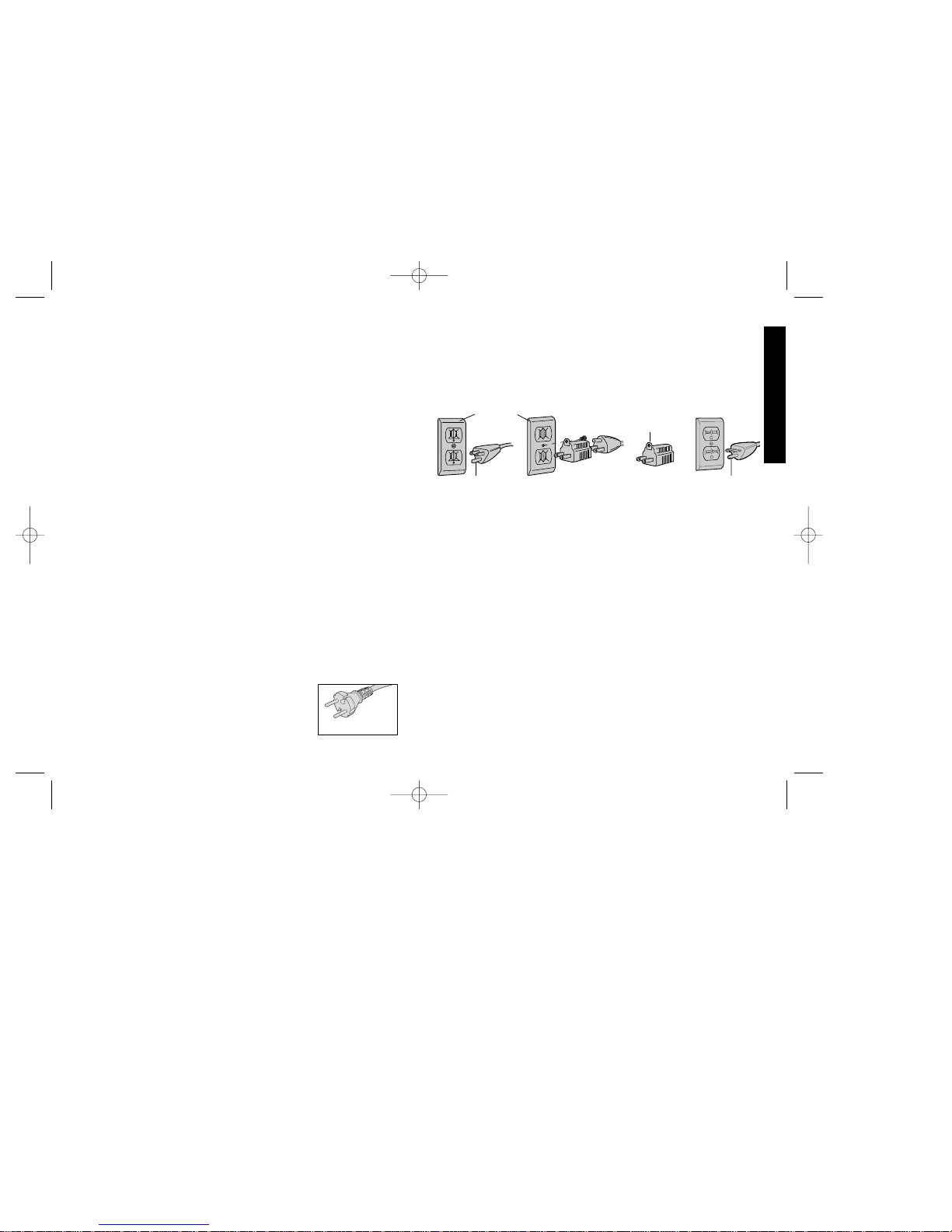
Grounding Instructions (DW870-220)
This tool should be grounded while in use to protect the operator
from electric shock. The tool is equipped with a
3-conductor cord and 3-prong grounding type plug to fit the proper
grounding type receptacle. The green (or green and yellow)
conductor in the cord is the grounding wire. Never connect the
green (or green and yellow) wire to a live terminal. If your unit is
intended for use on less than 150 V, it has a plug that looks like
that shown in sketch A. If it is for use on 150 to 250 V, it has a plug
that looks like that shown in sketch D. An adapter, sketches B and
C, is available for connecting sketch A type plugs
to 2-prong receptacles. The green-colored rigid
ear, lug, or the like, extending from the adapter
must be connected to a permanent ground, such
as a properly grounded outlet box. No adapter is
available for a plug as shown in sketch D. ADAPTER SHOWN IN
FIGURES B and C IS NOT FOR USE IN CANADA. Use only 3wire extension cords that have 3-prong grounding-type plugs and 3pole receptacles that accept the tool’s plug. Replace or repair
damaged cords.
Additional Safety Rules for Chop Saws
• Always wear safety goggles or other eye protection when using this
tool.
• Before using, inspect each cutting wheel for cracks or flaws. If a
crack or flaw is evident—discard the wheel! The wheel should also
be inspected whenever you think the tool may have been dropped.
• When starting the tool (with a new or replacement wheel installed)
place the tool in a well protected area. If the wheel has an
undetected crack or flaw, it should burst in less than one minute.
Never start the tool with a person in line with the wheel. This
includes the operator.
• In operation, avoid bouncing the wheel or giving it rough treatment.
If this occurs, stop the tool and inspect the wheel.
• Clean your chop saw periodically following the procedure in this
manual.
• Do not remove wheel guard.
• Always use the vise or special fixturing to clamp work.
• Use only wheels rated at 4100 rpm or higher.
• Allow cut off parts to cool before handling.
• Do not attempt to cut wood or plastic with this tool.
AB CD
GROUNDING PIN
GROUNDED
OUTLET
BOX
GROUNDING
MEANS
GROUNDING PIN
ADAPTER
220 VOLT PLUG
DW870,220/383823 5/3/02 1:29 PM Page 1
Page 6
2
English
• NEVER CUT MAGNESIUM WITH THIS TOOL.
• Use chop saw in a well-ventilated area.
• Turn chop saw off before removing any pieces from the base.
• DO NOT CUT ELECTRICALLY LIVE MATERIAL.
• NEVER USE A CIRCULAR SAW BLADE IN THIS CHOP SAW.
DO NOT USE TOOTHED BLADES.
• DO NOT OPERATE THIS TOOL NEAR FLAMMABLE LIQUIDS,
GASES OR DUST. Sparks from cutting or motor may ignite dust
and fumes.
SAVE THESE INSTRUCTIONS
Power Supply
Be sure your power supply agrees with the nameplate marking.
120 volts, “60 Hz” means alternating current (normal 120 volt, 60
Hz house current).
A voltage decrease of more than 10% will cause a loss of power and
overheating.
Switch
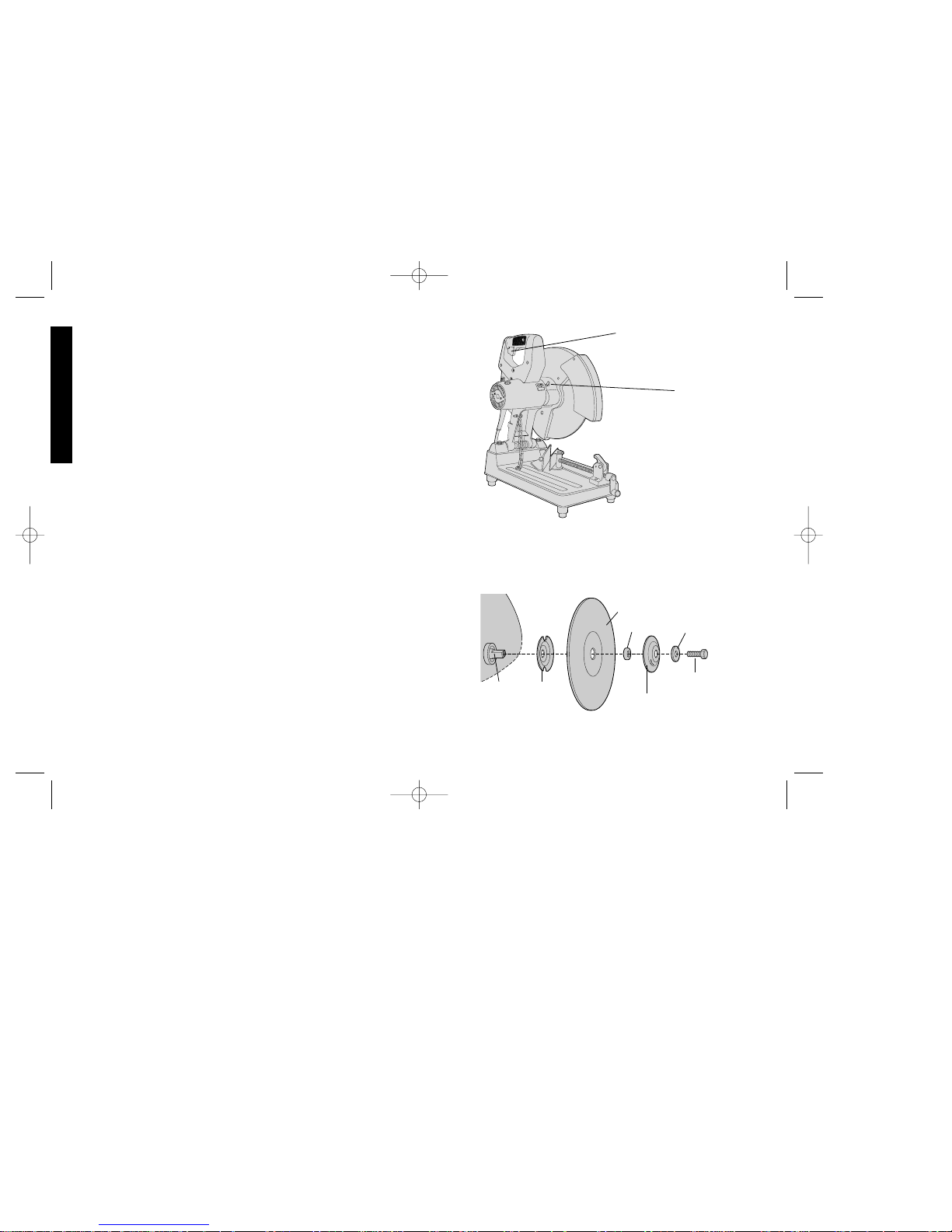
To start the tool, depress the trigger switch shown in Figure 1. To
turn the tool off, release the switch.
Features and Benefits
• AC/DC permits use with a DC power source such as a welder.
• Switch handle is human engineered for maximum convenience
when the saw is used on a bench, or on the floor.
• Lightweight, sure-grip carrying handle, and fold-down design
combine to make it easy to carry the machine from job to job.
• Rugged steel base with rubber padded feet provide durability
and vibration-free operation for stable cutting.
S
T
O
P
P
E
R
P
I
N
FIG. 1
TRIGGER SWITCH
BLADE LOCK
LEVER
FIG. 2
GEAR
SHAFT
FLANGE,
INSIDE
ABRASIVE WHEEL
ADAPTER
FLANGE, OUTSIDE
WASHER
HEX HEAD BOLT
DW870,220/383823 5/3/02 1:29 PM Page 2
Page 7
3
English
• Pivoting fence for convenience and accuracy in making miter
cuts. Right position graduations for 0°, 15°, 30° and 45°. Left
position graduations for 0°, 15° and 30°.
• Blade spindle lock simplifies and speeds blade changing.
• Blade/Fence wrench is conveniently stored in holder at rear of
base.
• Tough steel wheel guard protects operator from the wheel.
Spark guard in base minimizes escaping sparks and protects
surroundings.
• Heavy duty brush system extends brush life.
• High efficiency cooling fan and improved housing design assure
high airflow for cooler operation and long life.
• 8’ power supply cord with separate cord protector is convenient
and simplifies servicing.
• 100% ball and roller bearing construction for longer tool life.
Removal and Installation of Wheels
1. Be sure tool is disconnected from power supply.
2. Push in blade lock lever (Fig. 1) and rotate wheel by hand until
blade lock lever engages slot in inside flange to lock wheel.
Loosen the hex head bolt in the center of the abrasive wheel
with the wrench provided at rear of base. Bolt has right hand
thread.
3. Remove the bolt, washer, outside flange, adapter, and old
wheel (Fig. 2).
4. Install the new abrasive wheel by reversing the above steps.
Make sure adapter is on gear shaft and centered in wheel.
5. Do not overtighten bolt.
WARNING: Check the work surface that the chop saw rests on
when replacing with a new abrasive wheel. It is possible that the
wheel may contact the work surface (through the base) when the
arm is fully lowered.
DO NOT MAKE ANY ADJUSTMENTS WHILE WHEEL IS IN
MOTION. DO NOT MAKE ANY ADJUSTMENTS WHILE CHOP
SAW IS PLUGGED INTO POWER SUPPLY.
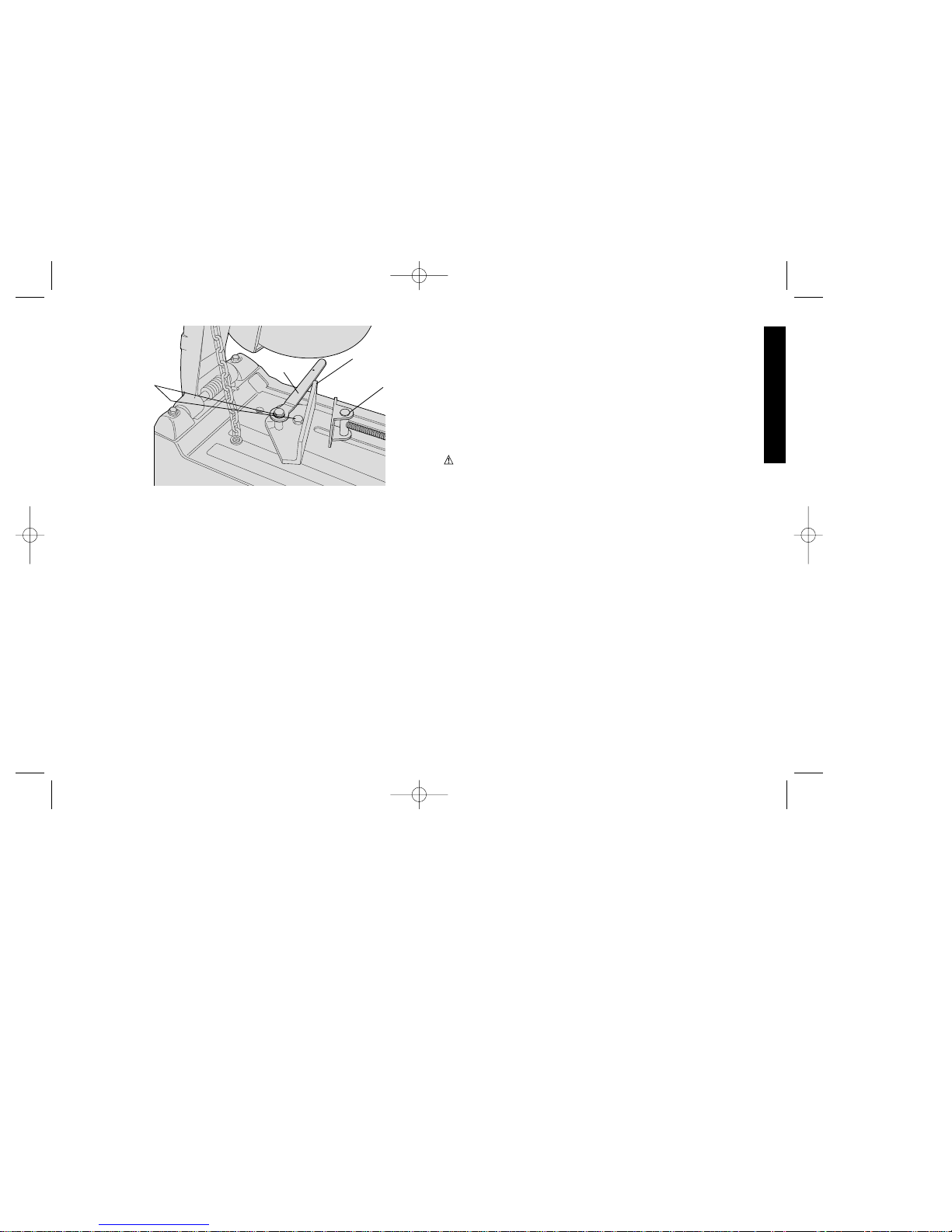
Quick Release Vise
Your saw features a quick release vise for greater convenience. To
release the vise, turn the crank handle a turn or two
counterclockwise to release the pressure on the vise jaw. With the
crank loose, lift the release lever on top of the moveable jaw, as
shown in Figure 3. Hold the lever up as you pull back on the crank
and open the jaws. When clamping an object, you need only to
push in the crank handle to the desired position. The moveable jaw
will slide freely until contact is made with the workpiece. Turn the
crank clockwise to clamp the workpiece in place.
To Adjust Vise Stop
CUTTING ANGLE
Use the wrench to loosen the two hex bolts (Fig. 3). (Do not
remove the bolts). The fence can be rotated in either direction.
Securely tighten both the bolts before use.
30
15
FIG. 3
WRENCH
FENCE
FENCE
BOLTS
VISE
DW870,220/383823 5/3/02 1:29 PM Page 3
Page 8
4
English
FIG. 4
30
15
1
5
0
4
5
30
FIG. 5
30
15
15
0
45
30
INDEX LINE
FIG. 6
FIG. 7
0.3"
7.62 mm
BRUSH
WEAR LINE
OPENING ADJUSTMENT
Remove both fence bolts. Move fence forward or backward to
desired location. Install both bolts. Tighten both bolts.
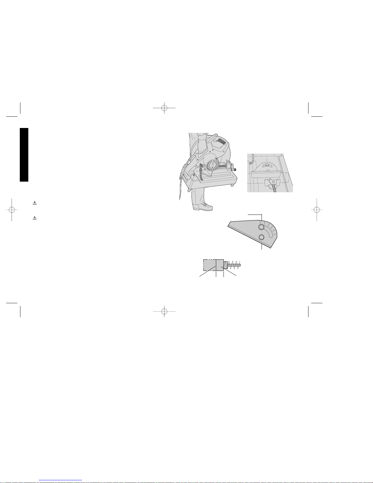
To Carry
Fold down unit to position where you can attach chain to pin on tool
arm (Fig. 4).
Cutting Capacity
The wide vise opening and high pivot point provide cutting capacity
for many large pieces. Use this chart to determine total maximum
size of cuts that can be made with a new wheel. Recommended
applications are: metal studs, electrical conduit up to 4" diameter,
bar stock and reinforcing bar up to 3/4" diameter.
NOTE: As cutting width increases, cutting height decreases.
CAUTION: CERTAIN LARGE , CIRCULAR OR IRREGULARLY SHAPED OBJECTS MAY REQUIRE ADDITIONAL
HOLDING MEANS.
CAUTION: DO NOT CUT MAGNESIUM WITH THIS TOOL.
Maximum Cutting Depth
To obtain maximum cutting depth, move the fence to the rear
position (Fig. 5).
NOTE: A new wheel, when pushed all the way down, will extend
below the base and cut into the work surface.
Degree Setting
Align the index line stamped in the base with the appropriate
degree for the desired angle of cut (Fig. 6). For very accurate cuts,
use a protractor.
DW870,220/383823 5/3/02 1:29 PM Page 4
Page 9

5
English
Maintenance of Tool
Lubrication
Closed-type, grease-sealed ball bearings are used throughout.
These bearings have sufficient lubrication packed in them at the
factory to last the life of the bearing.
Gears should be relubricated every 60 to 90 days, depending upon
use. This lubrication should only be attempted by experienced
power tool repairmen like the mechanics at D
EWALT certified
service centers. (See “Tools, Electric in yellow pages.) The gear
case should be wiped clean and 3/4 oz. (20 grams) of grease
placed in the gear case.
Cleaning
Blowing dust and grit out of the main housing by means of an air
hose is recommended and may be done as often as dirt is seen
collecting in and around the air vents.
Motor Brushes (Fig. 7)
Be sure tool is unplugged before inspecting brushes. Brushes
should be regularly inspected for wear. To inspect brushes,
unscrew the plastic brush caps (located in the sides of the motor
housing) and the spring and brush assemblies may be removed
from the tool. Keep brushes clean and sliding freely in their
guides. When the brushes wear to the point that the wear line
shown in Fig. 7 is even with the end of the brush holder, the
brush/spring assemblies (both) should be replaced.
Mounting Methods
To improve stability during use, the saw should be firmly mounted
as described below. To enhance the tool’s portability, it can be
bolted to a piece of 1/2" or thicker plywood which can be clamped
to a suitable horizontal work surface.
16-3/8"
(416 mm)
8-1/2"
(216 mm)
FIG. 8
S
T
O
P
P
E
R
P
I
N
FIG. 9
20"
2"-3"
NAIL
4"
NOTE: CAPACITY SHOWN ON THE FOLLOWING CHART
ASSUMES NO WHEEL WEAR.
FENCE AT FORWARD
POSITION
FENCE AT REAR
POSITION
6”
5”
4”
3”
2”
1”
0” 1” 2” 3” 4” 5” 6” 7” 8” 9”
4.75”
3.93”
6.25” 7.75”
HEIGHT
WIDTH
DW870,220/383823 5/3/02 1:29 PM Page 5
Page 10

6
English
manual. The use of any other accessory or attachment may be
hazardous. Use only D
EWALT 14", 4100 RPM saw blades.
ALWAYS WEAR SAFETY GLASSES. SECURE WORK IN VISE.
DISCONNECT TOOL FROM POWER SUPPLY BEFORE
CHANGING WHEEL.
Full Warranty
DEWALT heavy duty industrial tools are warranted for one year
from date of purchase. We will repair, without charge, any defects
due to faulty materials or workmanship. Arrangements have been
made with the Industrial Tool Division of Black & Decker (U.S.)
Inc. to provide warranty repairs for D
EWALT tools. Please return
the complete unit, transportation prepaid, to any Black & Decker
(U.S.) Inc. Industrial service center or authorized service station
listed under “Tools, Electric” in the yellow pages. This warranty
does not apply to accessories or damage caused where repairs
have been made or attempted by others. This warranty gives you
specific legal rights and you may have other rights which vary
from state to state.
In addition to the warranty, D
EWALT tools are covered by our:
30 DAY NO RISK SATISFACTION GUARANTEE
If you are not completely satisfied with the performance of your
D
EWALT heavy duty industrial tool, simply return it to the
participating seller within 30 days for a full refund. Please return the
complete unit, transportation prepaid. Proof of purchase may be
required.
Procedure For Permanent Mounting
1. Drill four holes, 5/16" diameter minimum, through the work
surface (Fig. 8).
2. Remove screws from feet.
3. Insert 1/4-20 screws through underside of work surface, through
feet, into holes in tool base. The proper screw length is equal to
the thickness of the work surface plus 1 inch
(25 mm).
Cradle Mounting (Fig. 9)
1. Cut two boards 20" long x 2" - 3" high x 4" wide.
2. Place chop saw at desired work location.
3. Place boards tightly along side, and nail to work surface
(Fig. 9).
Important!
To assure product SAFETY and RELIABILITY, repairs,
maintenance and adjustment (including brush inspection and
replacement) should be performed by authorized service centers or
other qualified service organizations, always using identical
replacement parts.
Accessories
Recommended accessories for use with your tool are available at
extra cost from your local dealer or authorized service center. A
complete listing of service centers is located at the end of this
manual If you need assistance in locating any accessory for your
tool, please contact your local dealer or authorized service center.
CAUTION: The use of any other accessory not recommended
for use with this tool could be hazardous.
CAUTION: Recommended saw blades for your saw are in this
DW870,220/383823 5/3/02 1:29 PM Page 6
Page 11

7
Français
Importantes mesures de sécurité pour
tous les outils
IMPORTANT : S’assurer que l’utilisateur lit attentivement et
comprend bien les mesures de sécurité avant de se servir l’outil.
AVERTISSEMENT : Afin de réduire les risques d'incendie, de
secousses électriques ou de blessures lorsqu'on utilise des outils
électriques, il faut toujours respecter les mesures de sécurité
suivantes.
LIRE TOUTES LES DIRECTIVES.
Importantes mesures de sécurité
• MAINTENIR LES PROTECTEURS EN PLACE et en bon état.
• ENLEVER LES CLÉS DE RÉGLAGE. Prendre l'habitude de
vérifier si les clés de réglage ont été retirées avant de faire
démarrer l'outil.
• BIEN DÉGAGER LA SURFACE DE TRAVAIL. Des surfaces et
des établis encombrés peuvent être la cause de blessures.
• TENIR COMPTE DU MILIEU DE TRAVAIL. Protéger les outils
électriques de la pluie. Ne pas s'en servir dans des endroits
humides ou mouillés. Bien éclairer la surface de travail.
• ÉLOIGNER LES ENFANTS. Tous les visiteurs doivent être tenus
à l'écart de l'aire de travail.
• S'ASSURER QUE L'ATELIER EST À L'ÉPREUVE DES
ENFANTS. Utiliser des cadenas, un interrupteur principal et
retirer les clés servant au démarrage.
• NE JAMAIS FORCER L'OUTIL. Afin d'obtenir un rendement sûr
et efficace, utiliser l'outil à son rendement nominal.
• UTILISER L'OUTIL APPROPRIÉ. Ne jamais exiger d'un petit
outil ou d'un accessoire le rendement d'un outil de fabrication plus
robuste.
• CORDONS DE RALLONGE. S'assurer que le cordon de rallonge
est en bon état. Lorsqu'on se sert d'un cordon de rallonge,
s'assurer qu'il est de calibre approprié pour la tension nécessaire
au fonctionnement de l'outil. L'utilisation d'un cordon de calibre
inférieur occasionne une baisse de tension entraînant une perte
de puissance et la surchauffe. Le tableau suivant indique le
calibre approprié selon la longueur du cordon et les mentions de
la plaque signalétique de l'outil. En cas de doute, utiliser un
cordon de calibre supérieur. Le chiffre indiquant le calibre est
inversement proportionnel au calibre du cordon.
Calibre minimal des cordons de rallonge
TensionLongueur totale du cordon en pieds
120 V 0-25 26-50 51-100 101-150
240 V 0-50 51-100 101-200 201-300
Intensité (A)
Au Au Calibre moyen de fil (AWG)
moins plus
0- 6 18 16 16 14
6 - 10 18 16 14 12
10 - 12 16 16 14 12
12 - 16 14 12 Non recommandé
• PORTER DES VÊTEMENTS APPROPRIÉS. Éviter de porter des
vêtements amples, des gants, des cravates, des bagues, des
bracelets et d'autres bijoux qui peuvent être happés par les pièces
en mouvement. Porter des chaussures à semelle antidérapante
pour travailler à l'extérieur. Protéger la chevelure si elle est
longue.
• TOUJOURS PORTER DES LUNETTES DE SÉCURITÉ. Porter
également un masque respiratoire si le travail de coupe produit de
la poussière. Les lentilles des verres correcteurs ordinaires
résistent seulement aux chocs; il ne s'agit pas de lunettes de
sécurité.
• NE PAS DÉPASSER SA PORTÉE. Toujours demeurer dans une
position stable et garder son équilibre.
• PRENDRE SOIN DES OUTILS. Conserver les outils propres et
DW870,220/383823 5/3/02 1:29 PM Page 7
Page 12

8
Français
affûtés pour qu'ils donnent un rendement supérieur et sûr.
Suivre les directives concernant la lubrification et le remplacement
des accessoires.
• DÉBRANCHER LES OUTILS NON UTILISÉS. Respecter cette
mesure lorsqu'on ne se sert pas de l'outil, ou qu'on doit le réparer
ou en changer un accessoire (comme une lame, un foret ou un
couteau).
• ÉVITER LES DÉMARRAGES ACCIDENTELS. S'assurer que
l'interrupteur est à la position hors circuit lorsqu'on branche l'outil.
• UTILISER DES ACCESSOIRES RECOMMANDÉS. Consulter le
guide d'utilisation pour connaître la liste des accessoires
recommandés. L'utilisation de tout autre accessoire présente des
risques de blessures.
• NE JAMAIS SE TENIR DEBOUT SUR L'OUTIL. Cela présente
des risques de blessures si l'outil bascule ou si on entre en
contact avec le tranchant par inadvertance.
• VÉRIFIER LES PIÈCES ENDOMMAGÉES. Avant de continuer
à utiliser l’outil, il faut vérifier si le protecteur ou toute autre pièce
endommagée remplit bien la fonction pour laquelle il a été prévu.
Vérifier l’alignement et les attaches des pièces mobiles, le degré
d’usure des pièces et leur montage, ainsi que tout autre facteur
susceptible de nuire au bon fonctionnement de l’outil. Faire
réparer ou remplacer tout protecteur ou toute autre pièce
endommagée .
• NE JAMAIS LAISSER L'OUTIL SANS SURVEILLANCE,
METTRE L'OUTIL HORS TENSION. Attendre l'immobilisation
complète de l'outil avant de s'en éloigner.
• PIÈCES DE RECHANGE. Lors de l'entretien, utiliser seulement
des pièces de rechange identiques.
Mise à la terre (DW870-220)
L'outil doit être mis à la terre lorsqu'on s'en sert
afin de protéger l'utilisateur contre les secousses
électriques. D'ailleurs, l'outil est muni d'un cordon
trifilaire et d'une fiche à trois broches convenant
aux prises mises à la terre. Le conducteur vert (ou vert et jaune) du
cordon constitue la mise à la terre. Ne jamais relier le conducteur
vert (ou vert et jaune) à une borne sous tension. Lorsque l'outil est
conçu pour être alimenté à une tension maximale de 150 volts, sa
fiche ressemble à celle illustrée à la figure A. Lorsque l'outil est
conçu pour être alimenté à une tension maximale de 150 à 250
volts, sa fiche ressemble à celle illustrée à la figure D. Il existe
des adaptateurs (figures B et C) pour brancher le type de fiche
illustré à la figure A dans des prises à deux trous. L'oreille ou la
cosse rigide et verte doit être reliée à une mise à la terre
permanente, comme une prise bien mise à la terre. Il n'y a pas
d'adaptateur pour les fiches semblables à celle illustrée à la figure
D. AU CANADA, ON NE PEUT PAS SE SERVIR DE
L'ADAPTATEUR ILLUSTRÉ AUX FIGURES B ET C. Utiliser
seulement des cordons de rallonge trifilaires ayant une fiche à 3
broches mise à la terre ainsi qu'une prise à 3 trous acceptant la
fiche de l'outil. Remplacer ou réparer les cordons de rallonge
endommagés.
Mesures de sécurité relatives aux scies
fendeuses
• Toujours porter des lunettes de sécurité ou tout autre dispositif de
protection pour les yeux en utilisant l'outil.
• Avant d'utiliser l'outil, vérifier si la meule comporte des fissures ou
des défectuosités. Le cas échéant, jeter la meule. Il faut
AB CD
BROCHE DE PRISE
MISE À LA TERRE
BROCHE DE PRISE
MISE À LA TERRE
PRISE MISE
À LA TERRE
DISPOSITIF DE
MISE À LA TERRE
ADAPTATEUR
BROCHE
220 V
DW870,220/383823 5/3/02 1:29 PM Page 8
Page 13

9
Français
également vérifier la meule lorsque l'outil est tombé.
• Lorsqu'on met l'outil en marche (avec une meule neuve ou de
rechange), il faut le tenir dans un endroit à l'écart et le laisser
fonctionner pendant une minute. Si la meule comporte une
fissure ou une défectuosité non décelée, elle éclate en moins
d'une minute. Ne jamais mettre l'outil en marche lorsqu'une
personne (y compris l'utilisateur) se trouve devant la scie.
• Éviter de faire faire un rebond à la meule ou de la manipuler
rudement. Le cas échéant, mettre l’outil hors circuit et inspecter
la meule.
• Nettoyer l’outil régulièrement conformément aux directives
d’entretien du présent guide.
• Ne jamais enlever le protecteur.
• Utiliser la bride de serrage pour fixer la pièce à découper.
• Utiliser seulement des meules d'une vitesse nominale d'au
moins 4 100 trs/min.
• Laisser refroidir les pièces découpées avant de les manipuler.
• Ne pas tenter de couper du bois ni du plastique avec l'outil.
• NE JAMAIS DÉCOUPER DU MAGNÉSIUM AVEC L'OUTIL.
• Utiliser la scie fendeuse seulement dans une pièce bien aérée.
• Mettre la scie fendeuse hors circuit avant de retirer les pièces qui
s'y trouvent.
• NE PAS COUPER UN MATÉRIAU SOUS TENSION.
• NE JAMAIS UTILISER UNE LAME DE SCIE CIRCULAIRE
AVEC LA SCIE FENDEUSE. NE PAS SE SERVIR DE LAMES À
DENTS.
• NE PAS UTILISER l'outil PRÈS DE LIQUIDES, DE GAZ OU DE
POUSSIÈRES INFLAMMABLES. Les étincelles que produit la
coupe ou le moteur en marche pourraient enflammer ces
produits.
CONSERVER CES MESURES.
Alimentation
Veiller à ce que la tension d'alimentation soit conforme aux
exigences de la plaque signalétique de l'outil. La mention «120
volts, 60 Hz» signifie que l'outil fonctionne seulement sur du courant
alternatif (courant domestique standard de 120 volts, 60 Hz).
Une baisse de tension de plus de 10 p. 100 entraîne une perte de
puissance et la surchauffe.
Interrupteur
Enfoncer la détente illustrée à la figure 1 pour mettre le moteur en
marche et la relâcher pour arrêter le moteur.
Caractéristiques et avantages
• L'alimentation en courant alternatif ou direct permet d'utiliser une
source de courant direct, comme une soudeuse.
• La poignée de l'interrupteur a été conçue afin d'en optimiser le
confort lorsqu'on se sert de la scie sur un établi ou sur le sol.
• La poignée légère et profilée se replie afin de faciliter le transport
de l'outil d'un endroit à un autre.
• Le socle robuste en acier est doté de pieds en caoutchouc afin
d'assurer la durabilité et le fonctionnement en douceur de l'outil.
• Le guide orientable pratique et précis permet de faire des coupes
en onglets à angles de 0°, 15°, 30° et 45° vers la droite, et à
angles de 0°, 15° et 30° vers la gauche.
• Le dispositif de verrouillage de l'arbre de la meule simplifie et
accélère le remplacement de la meule.
• La clé de démontage de la meule et du guide se range
commodément dans une case située à l'arrière du socle.
• Le robuste protecteur en acier de la meule protège l'utilisateur
des risques de coupe. Le pare-étincelles minimise les fuites
d'étincelles et les risques d'incendies.
• Le système de balais de service intensif prolonge la durée des
balais.
DW870,220/383823 5/3/02 1:29 PM Page 9
Page 14

10
Français
• Le ventilateur de rendement supérieur et le concept amélioré du
boîtier assure un fort débit d'air afin d'optimiser la ventilation et la
durée de l'outil.
• Le protège-cordon amovible du cordon d'alimentation de7,3 m
(8 pi) est des plus pratiques et il en simplifie l'entretien.
• L'outil est entièrement monté sur des roulements à billes et à
rouleaux afin d'en prolonger la durée.
Retrait et installation de la meule
1. S'assurer que l'outil est débranché.
2. Enfoncer le levier de verrouillage de la meule (fig. 1) et faire
tourner la meule à la main jusqu'à ce que le levier de verrouillage
de la meule s'enclenche dans la fente de la bride intérieure afin
de verrouiller la meule. Desserrer le boulon à tête hexagonale
qui se trouve au centre de la meule abrasive à l'aide de la clé
fournie à l'arrière du socle de l'outil. Le boulon est fileté à droite.
3. Retirer le boulon, la rondelle, la bride extérieure, l'adaptateur et
l'ancienne meule (fig. 2).
4. Installer la nouvelle meule abrasive en se conformant aux étapes
précédentes dans le sens inverse. S'assurer que l'adaptateur se
trouve sur l'arbre de transmission au centre de la meule.
5. Éviter de trop serrer le boulon.
AVERTISSEMENT : Vérifier la surface sur laquelle repose la
scie fendeuse lorsqu'on en remplace la meule abrasive. Cette
dernière pourrait entrer en contact avec la surface à ouvrer (du
côté du socle) lorsqu'on abaisse le bras de la scie.
N'EFFECTUER AUCUN RÉGLAGE LORSQUE LA MEULE
TOURNE. N'EFFECTUER AUCUN RÉGLAGE LORSQUE LA
SCIE FENDEUSE EST BRANCHÉE.
Bride de serrage à dégagement rapide
La scie comporte une bride de serrage à dégagement rapide pour
plus de commodité. Pour dégager la bride, faire tourner la
S
T
O
P
P
E
R
P
I
N
FIG. 1
INTERRUPTEUR
À DÉTENTE
LEVIER DE
VERROUILLAGE
DE LA LAME
FIG. 2
LEVIER DE
VITESSES
BRIDE
INTERNE
MEULE ABRASIVE
ADAPTATEUR
BRIDE EXTERNE
RONDELLE
BOULON À TÊTE
HEXAGONALE
30
15
FIG. 3
CLÉ
GUIDE
BOULONS
DU GUIDE
BRIDE DE
SERRAGE
FIG. 4
DW870,220/383823 5/3/02 1:29 PM Page 10
Page 15

11
Français
manivelle dans le sens antihoraire de un ou deux tours afin de
dégager la pression de la mâchoire. Desserrer la manivelle et
soulever le levier de dégagement sur le dessus de la mâchoire
mobile (fig. 3). Laisser le levier soulevé en tirant la manivelle vers
l'arrière et ouvrir les mâchoires. Pour fixer un objet, il suffit de
pousser la poignée de la manivelle dans la position voulue. La
mâchoire mobile glisse librement jusqu'à ce qu'elle entre en contact
avec la pièce à ouvrer. Faire tourner la manivelle dans le sens
horaire pour serrer la pièce à ouvrer.
Réglage de la bride de serrage
ANGLE de coupe
Utiliser la clé pour desserrer les deux boulons à tête hexagonale (fig.
3). (Ne pas retirer les boulons.) On peut faire tourner la réglette
dans un sens ou dans l'autre. Bien serrer les deux boulons avant
d'utiliser la scie de nouveau.
Réglage de l'ouverture
Retirer les deux boulons de la réglette. Déplacer la réglette vers
l'avant ou l'arrière selon la position voulue. Réinstaller les deux
boulons et bien les serrer.
Transport
Plier l'outil de façon à pouvoir attacher la chaîne à la tige du bras
(fig. 4).
Capacité de coupe
La grande ouverture de la bride de serrage ainsi que l'articulation
exceptionnelle de la scie permettent de couper de nombreuses
pièces de grandes dimensions. Utiliser le tableau suivant afin de
déterminer la dimension maximale totale de coupe que la nouvelle
meule peut faire. Il est conseillé de l'utiliser pour découper : des
montants métalliques, des conduites électriques d'un diamètre
maximal de 100 mm (4 po), des barres et des barres de
renforcement d'un diamètre maximal de 19 mm (3/4 po).
NOTE : Prière de noter que la largeur augmente pendant la coupe
tandis que la hauteur de coupe diminue.
MISE EN GARDE : IL PEUT ÊTRE NÉCESSAIRE DE FIXER
CERTAINS OBJETS DE DIMENSIONS EXTRAORDINAIRES,
CIRCULAIRES OU DE FORMES IRRÉGULIÈRES.
MISE EN GARDE : NE PAS COUPER DU MAGNÉSIUM AVEC LA
SCIE.
Profondeur de coupe maximale
Afin de maximiser la profondeur de coupe, déplacer la réglette vers
l'arrière (fig. 5).
NOTE : Lorsqu'on abaisse à fond une nouvelle meule, celle-ci
dépasse la base de l'outil et découpe la surface de travail.
Réglage des angles
Aligner la marque imprimée sur le socle sur l'angle de coupe
30
1
5
1
5
0
4
5
30
FIG. 5
30
15
15
0
45
30
MARQUE
SUR LE
SOCLE
FIG. 6
FIG. 7
0.3"
7.62 mm
BALAI
LIGNE
D'USURE
DW870,220/383823 5/3/02 1:29 PM Page 11
Page 16

12
Français
approprié (fig. 6). Utiliser un rapporteur afin d'obtenir des coupes
des plus précises.
NOTE : LES CAPACITÉS INDIQUÉES SUR CE TABLEAU NE
TIENNENT PAS COMPTE DE L'USURE DE LA MEULE.
Entretien de l'outil
Lubrification
L'outil est entièrement monté sur des roulements à rouleaux scellés
et graissés. Ces derniers sont lubrifiés en permanence à l'usine.
Il faut lubrifier les engrenages à des intervalles entre 60 et 90 jours,
selon le degré d'utilisation de l'outil. Il faut confier ces travaux à des
techniciens qualifiés comme ceux des centres de service de produits
DeWalt. Il faut essuyer l'outil et ajouter 20 grammes (3/4 oz) de
graisse dans le boîtier des engrenages.
Nettoyage
Il est conseillé de nettoyer le boîtier principal de l'outil en y soufflant
de l'air comprimé pour en chasser la poussière et les charpies dès
qu'il s'en accumule autour des évents.
Balais du moteur (Fig. 7)
S'assurer que l'outil est débranché avant d'en vérifier les balais. Il
faut examiner ces derniers régulièrement afin d'en observer le degré
d'usure. Pour ce faire, dévisser les bouchons en plastique (qui se
trouvent sur les côtés du carter de l'outil) et retirer les porte-balais de
l'outil. S'assurer que les balais sont propres et qu'ils glissent bien
dans leurs guides. Lorsque les balais sont usés jusqu'à la ligne
illustrée à la figure 7, il faut remplacer les balais et les porte-balais.
Montage
Afin d'améliorer la stabilité de l'outil pendant son utilisation, il faut
solidement monter la scie de la façon décrite plus bas. Pour
optimiser la mobilité de l'outil, on peut le visser à une pièce de
contreplaqué d'au moins 13 mm (1/2 po) qu'on fixe ensuite à une
surface de travail horizontale appropriée.
16-3/8"
(416 mm)
8-1/2"
(216 mm)
FIG. 8
S
T
O
P
P
E
R
P
I
N
FIG. 9
20"
2"-3"
CLOU
4"
GUIDE À LA POSITION
AVANT
GUIDE À LA POSITION
ARRIÈRE
6”
5”
4”
3”
2”
1”
0” 1” 2” 3” 4” 5” 6” 7” 8” 9”
4.75”
3.93”
6.25” 7.75”
HAUTEUR
LARGEUR
DW870,220/383823 5/3/02 1:29 PM Page 12
Page 17

13
Français
Montage permanent
1. Percer quatre trous d'un diamètre minimal de 8 mm (5/16 po)
dans la surface de travail (fig. 8).
2. Retirer les vis des pieds de la base.
3. Insérer des vis nº 20 de 7 mm (1/4 po) sous la surface de
travail jusque dans les pieds de la base. La longueur appropriée
de la vis correspond à l'épaisseur de la surface de travail plus
25 mm (1 po).
Montage sur chevalet (Fig. 9)
1. Découper deux planches d'une longueur de 508 mm (20 po) sur
une hauteur de 50 à 76 mm (de 2 à 3 po), sur une largeur de
100 mm (4 po).
2. Placer la scie fendeuse à l'emplacement voulu.
3. Placer les deux planches tout contre chaque côté de la scie et les
clouer dans la surface de travail (fig. 9).
Important!
Pour assurer la SÉCURITÉ D’EMPLOI et la FIABILITÉ de l’outil,
n’en confier la réparation, l’entretien et les rajustements (y compris
l'inspection et le remplacement des balais) qu’au personnel d'un
centre de service ou d'un atelier d’entretien autorisé n’utilisant que
des pièces de rechange identiques.
Accessoires
Les accessoires recommandés pour l’outil sont vendus séparément
chez les détaillants et au centre de service de la région. La liste
complète des centres de service se trouve à la fin du présent guide.
Pour trouver un accessoire, communiquer avec les détaillants ou le
centre de service de la région.
MISE EN GARDE : L’utilisation de tout accessoire non
recommandé peut être dangereuse.
MISE EN GARDE : Les meules recommandées pour l'outil sont
indiquées dans le présent guide. L’utilisation de tout autre
accessoire peut être dangereuse. Utiliser seulement des meules
DeWalt de 350 mm (14 po) et de 4 100 trs/min.
TOUJOURS PORTER DES LUNETTES DE SÉCURITÉ. FIXER LA
PIÈCE À OUVRER DANS LA BRIDE DE SERRAGE.
DÉBRANCHER L'OUTIL AVANT D'EN REMPLACER LA MEULE.
Garantie complète
Les outils industriels de service intensif DeWALT sont garantis
pendant un an à partir de la date d’achat. Toute pièce d’un outil
DeWALT qui s’avérait défectueuse en raison d’un vice de matière ou
de fabrication sera réparée ou remplacée sans frais. Selon une
entente convenue entre DeWALT et la Division des outils industriels
de Black & Decker, celle-ci s’engage à effectuer les réparations
couvertes par la présente garantie. Il suffit de retourner l’outil port
payé à l’un des centres de service d’outils industriels Black &
Decker ou à tout autre atelier d’entretien d’outils industriels inscrit à
la rubrique «Outils électriques» des Pages Jaunes. La présente
garantie ne couvre pas les accessoires ni les dommages causés
par des réparations tentées ou effectuées par des tiers. Les
modalités de la présente garantie donnent des droits légaux
spécifiques. L'utilisateur peut également se prévaloir d'autres droits
selon l'état ou la province qu'il habite.
En outre, la garantie suivante couvre les outils DeWALT.
GARANTIE DE SATISFACTION DE 30 JOURS OU ARGENT
REMIS
Si, pour quelque raison que ce soit, l'outil industriel de service
intensif DeWalt ne donne pas entière satisfaction, il suffit de le
retourner chez le marchand participant dans les 30 jours suivant la
date d'achat afin d'obtenir un remboursement complet. Il faut
retourner, port payé, l'outil complet. On peut exiger une preuve
d'achat.
Voir la rubrique “Outils électriques”
des Pages Jaunes
pour le service et les ventes.
IMPORTADOR: BLACK & DECKER S.A. DE C.V.
BOSQUES DE RADIATAS NO. 42
BOSQUES DE LAS LOMAS, 05120 MEXICO, D.F.
TEL 326-7100
DW870,220/383823 5/3/02 1:29 PM Page 13
Page 18

14
Español
INSTRUCCIONES IMPORTANTES DE
SEGURIDAD PARA TODAS LAS
HERRAMIENTAS
IMPORTANTE: Por favor, asegúrese que la persona que emplee
este equipo lea cuidadosamente estas instrucciones y las entienda
antes de iniciar las operaciones.
ADVERTENCIA: Es indispensable sujetarse a las precauciones
básicas de seguridad, con la finalidad de reducir el peligro de
incendio, choque eléctrico y lesiones personales, en todas las
ocasiones en que se utilicen herramientas eléctricas. Entre estas
precauciones se incluyen las siguientes.
LEA TODAS LAS INSTRUCCIONES
Instrucciones de seguridad para todas
las herramientas
• CONSERVE LAS GUARDAS EN SU SITIO y listas para el
trabajo.
• RETIRE LAS LLAVES DE AJUSTE Y OTRAS
HERRAMIENTAS. Hágase el hábito de revisar para verificar que
las llaves se hayan retirado de la herramienta antes de
encenderla.
• CONSERVE LIMPIA EL AREA DE TRABAJO. Los lugares y los
bancos desordenados propician los accidentes.
• NO SE UTILICE EN AMBIENTES PELIGROSOS. No utilice
herramientas eléctricas en lugares húmedos o inundados, ni las
exponga a la lluvia. Conserve el área de trabajo bien iluminada.
• CONSERVE APARTADOS A LOS NIÑOS. Todos los visitantes
deben permanecer a distancia segura del área de trabajo.
• HAGA SU TALLER A PRUEBA DE NIÑOS con candados,
interruptores maestros o quitando las llaves de encendido.
• NO FUERCE LA HERRAMIENTA. Esta hará el trabajo mejor y de
manera más segura bajo las especificaciones para las que se
diseñó.
• UTILICE LA HERRAMIENTA ADECUADA. No fuerce a una
herramienta o sus dispositivos a hacer trabajos para los que no
se han diseñado.
• UTILICE CABLES DE EXTENSION ADECUADOS. Asegúrese
que su cable de extensión esté en buenas condiciones. Cuando
utilice una extensión, asegúrese que tenga el calibre necesario
para soportar la corriente que su herramienta requiere. Un cale
con calibre menor causará una caída en el voltaje de la línea,
ocasionando pérdida de potencia y sobrecalentamiento. El
cuadro siguiente muestra el calibre correcto para usarse de
acuerdo con la longitud y el amperaje descrito en la placa de
identificación. Si tiene dudas, utilice el calibre siguiente. Mientras
más pequeño sea el número del calibre, mayor será su
capacidad.
Calibre mínimo requerido (AWG) para cables de extensión
Volts Longitud total de la extensión
(metros)
120 V 0 - 7.5 7.6 - 15.2 15. 3 - 30.4 30.5 - 45.7
240 V 0 - 15.2 15.3 - 30.4 30.5 - 60.8 60.9 - 121.2
Amperaje en la placa de identificación
Más No más Calibre promedio del alambre
de de
0 - 6 18 16 16 14
6 - 10 18 16 14 12
10 - 12 16 16 14 12
12 - 16 14 12 No se recomienda
• UTILICE LAS ROPAS ADECUADAS. No utilice prendas flojas,
guantes corbatas, anillos brazaletes ni otros artículos de joyería
que pudiesen quedar atrapados por las piezas en movimiento. Se
recomienda el uso de calzado antiderrapante. Cúbrase el cabello
DW870,220/383823 5/3/02 1:29 PM Page 14
Page 19

15
Español
si lo tiene largo.
• SIEMPRE UTILICE ANTEOJOS DE SEGURIDAD. También
utilice una máscara contra polvo si la operación que efectuará lo
produce. Los anteojos de diario solamente tienen lentes
resistentes al impacto, no son anteojos de seguridad.
• NO SE SOBREEXTIENDA. Conserve los pies bien apoyados, lo
mismo que el equilibrio.
• CUIDE SUS HERRAMIENTAS. Consérvelas afiladas y limpias
para un rendimiento más seguro y más eficaz. Siga las
instrucciones para la lubricación y el cambio de accesorios.
• DESCONECTE LAS HERRAMIENTAS antes de darles servicio
y cuando cambie de accesorios, tales como discos, brocas,
cuchillas, y otros similares.
• EVITE EL RIESGO DE ENCENDIDO ACCIDENTAL. Asegúrese
que el interruptor esté en posición de apagado antes de conectar
la herramienta.
• UTILICE LOS ACCESORIOS RECOMENDADOS. Consulte el
manual de instrucciones para conocer los accesorios
recomendados. El empleo de accesorios no apropiados puede
ocasionar riesgos de lesiones a las personas.
• NUNCA SE PARE EN LA HERRAMIENTA. Se puede lesionar
gravemente si la herramienta se vuelca o hace contacto accidental
con la pieza de corte.
• REVISE LAS PARTES DAÑADAS. Antes de seguir utilizando la
herramienta, una guarda u otra pieza que esté dañada debe ser
examinada cuidadosamente para determinar si funcionará
apropiadamente y cumplirá con su función. Revise la alineación de
las piezas móviles, su montaje, la ruptura de las piezas, montajes
y cualesquiera otras condiciones que pudiesen afectar su
operación. Una guarda u otra parte dañada debe ser reparada
correctamente o reemplazada.
• NUNCA DEJE LA HERRAMIENTA EN OPERACION
DESATENDIDA. APAGUELA. No deje la herramienta hasta que
se haya detenido completamente.
• PARTES DE REPUESTO. Utilice únicamente piezas de repuesto
idénticas cuando haga servicio.
• ASEGURE LAS PIEZAS DE TRABAJO. Utilice prensas para
sujetar su trabajo cuando le sea práctico. Esto es más seguro que
usar sus manos y le deja ambas libres para operar la herramienta.
Instrucciones de aterrizaje (DW870-220)
Esta herramienta debe conectarse a tierra para
proteger al operador de choques eléctricos. Esta
unidad está equipada con un cordón eléctrico de
tres hilos aprobado y una clavija para aterrizaje de
tres patas para conectarse a la toma de corriente
adecuada. El conductor verde (o verde y amarillo)
es el cable de tierra. Nunca conecte el cable verde (o verde y amarillo)
a una terminal viva. Si su unidad está hecha para funcionar con menos
de 150 volts, tiene una clavija similar a la que se muestra en la figura
A. Si es para usarse con corriente de 150 a 250 volts, tiene una
clavija como la que se muestra en la figura D. Hay adaptadores,
figuras B y C, para conectar clavijas del tipo de la figura A a tomas de
corriente para dos patas. La oreja de color verde deberá conectarse a
tierra permanente, tal como una toma de corriente aterrizada
adecuadamente. No hay adaptadores para clavijas como la de la
figura D. EL ADAPTADOR MOSTRADO EN LAS FIGURAS B Y C NO
ESTA HECHO PARA USARSE EN CANADA. Unicamente utilice
cordones de extensión que tengan clavijas de tres patas y tomas de
corriente de tres ranuras que acepten estas clavijas. Reemplace o
repare los cordones eléctricos dañados.
CLAVIJA PARA
220 V
AB CD
PATA DE CONEXION A TIERRA
TOMA DE
CORRIENTE
ATERRIZADA
MEDIO DE
ATERRIZAJE
PATA DE
CONEXION A TIERRA
ADAPTADOR
DW870,220/383823 5/3/02 1:29 PM Page 15
Page 20

16
Español
Reglas de seguridad adicionales para
cortadoras de metales
• Utilice siempre anteojos de seguridad u otra protección ocular
cuando emplee esta herramienta.
• Antes de usar un disco, revíselo en busca de cuarteaduras o
fallas. Si tales son evidentes, deseche el disco. También deberá
inspeccionar el disco si piensa que la herramienta pudo haber
caído.
• Cuando encienda la herramienta (con un disco nuevo o después
de haberlo cambiado) colóquela en un área bien protegida. Si la
herramienta tiene una falla o cuarteadura no detectada, el disco
estallará en menos de un minuto. Nunca encienda la herramienta
con una persona parada en línea con el disco; esto incluye al
operador.
• Durante la operación, evite que el disco rebote, no lo trate
descuidadamente. Si esto ocurre, apague la herramienta y revise
el disco.
• Limpie la sierra periódicamente siguiendo el procedimiento
descrito en este manual.
• No quite la guarda del disco.
• Utilice siempre la prensa o el dispositivo especial para sujetar la
pieza de trabajo.
• Utilice siempre discos especificados para 4100 o más rpm.
• Permita que las partes cortadas se enfríen antes de manipularlas.
• No intente cortar madera o plástico con esta herramienta.
• NUNCA CORTE MAGNESIO CON ESTA HERRAMIENTA.
• Utilice la cortadora de metales en un área bien ventilada.
• Apague la cortadora antes de retirar cualquier pieza de la base.
• NO CORTE MATERIAL ELECTRICAMENTE VIVO.
• NUNCA UTILICE UN DISCO PARA SIERRA CIRCULAR EN
ESTA HERRAMIENTA. NO UTILICE DISCOS DENTADOS.
• NO UTILICE ESTA HERRAMIENTA CERCA DE LIQUIDOS,
GASES O POLVOS INFLAMABLES. Las chispas emitidas por el
motor pueden originar las ignición de estos polvos o vapores.
CONSERVE ESTAS
INSTRUCCIONES
Alimentación
Asegúrese que su fuente de alimentación concuerde con la
especificada en la placa de identificación de la herramienta. “120
volts, 60 Hz” significa corriente alterna (corriente doméstica normal
de 120 volts a 60 ciclos).
Disminuciones en el voltaje superiores al 10% causarán pérdida de
potencia y sobrecalentamiento.
Interruptor
Para encender la herramienta, oprima el interruptor de gatillo
ilustrado en la figura 1. Para apagar la herramienta, libere el
interruptor.
Características y beneficios
• Al poder utilizar corriente alterna y corriente continua es posible
emplear una fuente de poder portátil, tal como una planta de
soldar.
• El mango del interruptor está diseñado pensando en el factor
humano para máxima comodidad al usar la sierra en una banca,
o en el piso.
• El peso ligero, el mango de acarreo de empuñadura segura, y el
diseño plegable se combinan para facilitar el transporte de la
máquina de un lado a otro.
• Resistente base de acero con patas de goma que permiten
durabilidad y operación libre de vibraciones para cortes estables.
• Guía giratoria para comodidad y precisión en cortes angulares.
Graduaciones a la derecha para 0°, 15ª, 30ª y 45ª. Graduaciones
a la izquierda para 0ª, 15ª, 30ª.
• Seguro en la flecha que simplifica el cambio de discos.
DW870,220/383823 5/3/02 1:29 PM Page 16
Page 21

17
Español
• La llave para el disco y la guía se guarda en la parte posterior de
la base.
• Guarda para el disco en acero que protege al operador. La
guarda contra chispas en la base reduce el número de chispas
que escapan y protege a los alrededores.
• Sistema de carbones para trabajo pesado de larga duración.
• El ventilador de alta eficiencia y el diseño mejorado de la carcaza
aseguran un alto flujo de aire para una operación más fría y
mayor durabilidad.
• Cable de alimentación de 2,4 m con protector por separado que
simplifica el servicio.
• Construcción 100% con baleros de bolas y rodillos para mayor
duración de la herramienta.
Remoción e instalación de discos
1. Asegúrese que la herramienta esté desconectada de la toma de
corriente.
2. Empuje la palanca del disco (Fig. 1) y gire el disco con la mano
hasta que la palanca se enganche con la ranura de la arandela
interior para fijar el disco. Afloje el tornillo con cabeza hexagonal
que se encuentra en el centro del disco abrasivo con la llave que
le proporcionamos. El tornillo tiene cuerda derecha.
3. Quite el tornillo, la roldana, la arandela exterior, el adaptador, y
el disco viejo (Fig. 2).
4. Instale el nuevo disco abrasivo invirtiendo los pasos anteriores.
Asegúrese que el adaptador esté en el eje de engranaje y
centrado en el disco.
5. No apriete excesivamente el tornillo.
ADVERTENCIA: Revise la superficie de trabajo sobre la que
descansa la cortadora cuando cambie de disco abrasivo. Es posible
que el disco haga contacto con la superficie de trabajo (a través de
la base) cuando se baja el brazo totalmente.
S
T
O
P
P
E
R
P
I
N
FIG. 1
INTERRUPTOR DE
GATILLO
PALANCA DE
SEGURO DEL
DISCO
FIG. 2
EJE DE
ENGRANAJE
ARANDELA
INTERIOR
DISCO ABRASIVO
ADAPTADOR
ARANDELA
EXTERIOR
ROLDANA
TORNILLO CON
CABEZA
HEXAGONAL
DW870,220/383823 5/3/02 1:29 PM Page 17
Page 22

18
Español
determinar el tamaño total máximo de los cortes que pueden
hacerse con un disco nuevo. Las aplicaciones recomendadas son:
pernos metálicos, conduit hasta de 10 cm de diámetro y barras de
refuerzo hasta de 19 mm de diámetro.
NOTA: Al aumentar el ancho de corte se disminuye la altura de
corte.
PRECAUCION: ALGUNOS OBJETOS GRANDES CON FORMA
CIRCULA IRREGULAR PUEDEN REQUERIR DE MEDIOS DE
SUJECION ADICIONALES.
PRECAUCION: NO CORTE MAGNESIO CON ESTA
HERRAMIENTA.
Profundidad máxima de corte
Para obtener la profundidad máxima de corte, mueva la guía a la
posición trasera (Fig. 5).
NOTA: Un disco nuevo, cuando se baja completamente, se
extenderá por debajo de la base y cortará la superficie de trabajo.
Ajuste de inclinación
Haga coincidir la línea indicadora grabada en la base con el número
30
15
FIG. 3
LLAVE
GUIA
TORNILLO
S DE LA
GUIA
PRENSA
NO HAGA NINGUN AJUSTE CUANDO EL DISCO ESTE EN
MOVIMIENTO. NO HAGA NINGUN AJUSTE CUANDO LA
CORTADORA ESTE CONECTADA A LA TOMA DE CORRIENTE.
Prensa de liberación rápida
Su cortadora cuenta con un sistema de liberación rápida para mayor
comodidad. Para liberar la prensa, gire la manivela una o dos
vueltas en sentido opuesto a las manecillas del reloj para reducir la
presión en la mordaza. Una vez floja la manivela, levante la palanca
de liberación que se encuentra en la parte superior de la mordaza
móvil, como se muestra en la figura 3. Sujete arriba la palanca
mientas tira de la manivela y abre las mordazas. Cuando prense un
objeto, usted solo necesita empujar el mango de la manivela hasta
la posición deseada. Una mordaza móvil se deslizará libremente
hasta hacer contacto con la pieza de trabajo. Gire la manivela en el
sentido de las manecillas del reloj para sujetar la pieza en posición.
Ajuste de los topes de prensa
ANGULO DE CORTE
Utilice la llave para aflojar los dos tornillos con cabeza hexagonal
(Fig. 3). (No saque los tornillos.) La guía puede girarse en cualquier
dirección. Apriete con firmeza ambos tornillos antes de emplear la
cortadora.
AJUSTE DE LA ABERTURA
Saque ambos tornillos de la guía. Mueva la guía hacia adelante o
hacia atrás hasta la posición que desee. Instale ambos tornillos y
apriételos.
Acarreo
Pliegue la unidad hasta la posición en que pueda enganchar la
cadena al perno del brazo de la herramienta (Fig. 4).
Capacidad de corte
La gran abertura de prensa y el alto punto de giro proporcionan
capacidad para cortar piezas grandes. Utilice la tabla para
DW870,220/383823 5/3/02 1:29 PM Page 18
Page 23

19
Español
apropiado para el ángulo de corte que desee (Fig. 6). Para cortes
muy precisos, utilice un protractor.
NOTA : LA CAPACIDAD ILUSTRADA EN LA TABLA SIGUIENTE
ASUME QUE NO HAY DESGASTE EN EL DISCO.
Mantenimiento de la herramienta
Lubricación
Se han empleado en toda su herramienta rodamientos engrasados
sellados, de tipo cerrado. Estos rodamientos cuentan con la
lubricación necesaria en su interior para toda su vida útil.
Los engranes deben lubricarse cada 60 a 90 días de acuerdo con el
uso. Esta lubricación solamente deberá realizarla personal experto
como los mecánicos de los centros de servicio autorizados
DeWALT. (Busque “ herramientas eléctricas” en la sección
amarilla.) La caja de engranes debe limpiarse y después deben
agregarse 20 gr. (3/4 de oz.) de grasa.
Limpieza
Se recomienda sopletear la carcaza principal con aire comprimido
con la frecuencia que la mugre se acumule dentro y alrededor de las
tomas de aire.
Carbones del motor (Fig. 7)
Asegúrese que la herramienta esté desconectada antes de revisar
los carbones. Estos deben revisarse con regularidad en busca de
desgaste. Para inspeccionar los carbones, destornille las tapas de
plástico (Se encuentran a los lados de la carcaza del motor) y saque
los montajes de resortes y carbones de la herramienta. Conserve
los carbones limpios y deslizándose libremente en sus guías.
Cuando los carbones se desgasten hasta el punto en que la línea
de desgaste ilustrada en la figura 7 este al ras del extremo del
porta carbones, deberán reemplazarse ambos carbones.
Métodos de montaje
Para aumentar la estabilidad durante el uso, la sierra debe
FIG. 4
30
1
5
1
5
0
4
5
30
FIG. 5
30
15
15
0
45
30
LINEA INDICADORA
FIG. 6
FIG. 7
0.3"
7.62 mm
CARBON
LINEA DE
DESGASTE
DW870,220/383823 5/3/02 1:29 PM Page 19
Page 24

20
Español
montarse con firmeza como se describe a continuación. Para
aumentar la portabilidad de la herramienta, puede atornillarse a una
pieza de madera contraplacada de 13 mm de espesor (o mayor),
misma que puede prensarse a una superficie de trabajo horizontal.
Procedimiento para montaje permanente
1. Perfore cuatro orificios con diámetro mínimo 8 mm (5/16”) a
través de la superficie de trabajo (Fig. 8).
2. Quite los tornillos de las patas.
3. Inserte tornillos 1/4-20 desde el lado inferior de la superficie de
trabajo, a través de las patas dentro de los orificios de la base de
la herramienta. La longitud apropiada para los tornillos es igual
al espesor de la superficie de trabajo mas 25 mm.
Montaje de cuna (Fig. 9)
1. Corte dos tablas de 50 cm. de largo por 5 a 7,5 cm de altura por
10 cm de ancho.
2. Coloque la cortadora de metales en el lugar que desee.
3. Coloque las tablas juntas a lo largo de los laterales y clávelas a
la superficie de trabajo (Fig. 9).
Importante
Para garantizar la SEGURIDAD y la CONFIABILIDAD del producto,
las reparaciones, el mantenimiento y los ajustes (incluyendo
inspección y cambio de carbones) deberán realizarse en los centros
de servicio autorizado u otras organizaciones de servicio calificado
que empleen siempre refacciones originales.
Accesorios
Los accesorios recomendados para emplearse con su herramienta
están a su disposición con costo adicional con su distribuidor o
centro de servicio autorizado. Se incluye una lista completa de los
centros de servicio al final de este manual. Si necesita ayuda para
encontrar cualquier accesorio para su herramienta, por favor
16-3/8"
(416 mm)
8-1/2"
(216 mm)
FIG. 8
S
T
O
P
P
E
R
P
I
N
FIG. 9
20"
2"-3"
CLAVO
4"
GUIA EN LA POSICION
DELANTERA
GUIA EN LA POSICION
TRASERA
6”
5”
4”
3”
2”
1”
0” 1” 2” 3” 4” 5” 6” 7” 8” 9”
4.75”
3.93”
6.25” 7.75”
ALTURA
ANCHO
NOTA : LA CAPACIDAD ILUSTRADA EN LA TABLA SIGUIENTE
ASUME QUE NO HAY DESGASTE EN EL DISCO.
DW870,220/383823 5/3/02 1:29 PM Page 20
Page 25

21
Español
PARA REPARACION Y SERVICIO DE SUS HERRAMIENTAS
ELECTRICAS FAVOR DE DIRIGIRSE AL CENTRO DE SERVICIO MAS
CERCANO
CULIACAN
Av. Nicolas Bravo #1063 Sur (91 671) 242 10
GAUDALAJARA
Av. La Paz #1770 (91 3) 826 69 78.
LEON
Polara #32 (91 471) 314 56
MEXICO
Eje Lázaro Cárdenas No. 18 Local D, Col. Obrera 553-9979
MERIDA
Calle 63 #459 (91 99) 23 54 90
MONTERREY
Av. Francisco I. Madero Pte. 1820-A (91 83) 72 11 25
PUEBLA
17 Norte #2057 (91 22) 46 90 20
QUERETARO
Av. Madero 139 Pte. (91 42) 14 60 60
SAN LOUIS POTOSI
Pedro Moreno #408 Fracc. la Victoria (91 48) 14 25 67
TORREON
Blvd. Independencia, 96 pte. (91 17) 16 52 65
VERACRUZ
Prolongación Diaz Miron #4280 (91 29) 21 70 18
VILLAHERMOSA
Zaragoza #105 (91 93) 12 53 17
PARA OTRAS LOCALIDADES LLAME AL: 326 7100
comuníquese con el distribuidor o centro de servicio autorizado de
su localidad.
PRECAUCION: El uso de cualquier accesorio no recomendado
para emplearse con su herramienta puede ser peligroso.
PRECAUCION: Los discos recomendados para emplearse con
su herramienta se indican en este manual. El empleo de cualquier
otro accesorio o dispositivo puede ser peligrosos. utilice únicamente
discos DeWALT de 355 mm (14”) para 4100 rpm.
UTILICE SIEMPRE GAFAS DE SEGURIDAD. ASEGURE LA
PIEZA DE TRABAJO EN LA PRENSA.
DESCONECTE LA HERRAMIENTA DE LA TOMA DE CORRIENTE
ANTES DE CAMBIAR EL DISCO.
Accesorios
Dispone usted de los accesorios para su herramienta con cargo
adicional con su distribuidor local autorizado o centro de servicio
autorizado.
PRECAUCION: Es peligroso emplear cualquier accesorio no
recomendado para emplearse con esta herramienta.
Importante
Para garantizar la SEGURIDAD y la CONFIABILIDAD, deberán
hacerse reparaciones, mantenimiento y ajustes de esta herramienta
(inclusive inspección y cambio de carbones) en los centros
autorizados de servicio u otras organizaciones autorizadas que
empleen siempre refacciones legítimas.
DW870,220/383823 5/3/02 1:29 PM Page 21
Page 26

22
Español
Garantía Completa
Las herramientas industriales DEWALT están garantizadas durante
un año a partir de la fecha de compra. Repararemos, sin cargos,
cualquier falla debida a material o mano de obra defectuosos. Hemos
hecho arreglos con la División de Herramientas Industriales de Black
& Decker para que hagan las reparaciones en garantía a las
herramientas D
EWALT. Por favor regrese la unidad completa, con el
transporte pagado, a cualquier Centro de Servicio para Herramientas
Industriales de Black & Decker o a las estaciones de servicio
autorizado enlistadas bajo “Herramientas Eléctricas” en la Sección
Amarilla. Esta garantía no se aplica a los accesorios ni a daños
causados por reparaciones efectuadas por terceras personas. Esta
garantía le otorga derechos legales específicos, y usted puede tener
otros derechos que pueden variar de estado a estado.
En adición a la garantía, las herramientas D
EWALT están amparadas
por nuestra:
GARANTIA DE SATISFACCION SIN RIESGO POR 30 DIAS
Si usted no se encuentra completamente satisfecho con el
desempeño de su herramienta industrial DEWALT, sencillamente
devuélvala a los vendedores participantes durante los primeros 30
días después de la fecha de compra para que le efectúen un
reembolso completo. Por favor regrese la unidad completa, con el
transporte pagado. Se puede requerir prueba de compra.
IMPORTADO: BLACK & DECKER S.A. DE C.V.
AVE CENTRAL 186 COL. NVA. IND.
VALLEJO C.P. 07700 MÉXICO, D.F.
TEL 747-95-00
SECCI N
AMARILLA
Si funciona…
y funciona muy bien.
Para servicio y ventas consulte
“HERRAMIENTAS ELECTRICAS”
en la sección amarilla.
DW870,220/383823 5/3/02 1:29 PM Page 22
 Loading...