

Page 1

DEWALT Industrial Tool Co., 701 East Joppa Road, Baltimore, MD 21286 Printed in U.S.A. (JUN98-CD-1) Form No. 384621-01
DW866 Copyright © 1998
384621-01/DW866 1/8/02 2:27 PM Page 2
Page 2

INSTRUCTIVO DE OPERACIÓN, CENTROS DE SERVICIO Y PÓLIZA
DE GARANTÍA. ADVERTENCIA: LÉASE ESTE INSTRUCTIVO ANTES
DE USAR EL PRODUCTO.
INSTRUCTION MANUAL
GUIDE D'UTILISATION
MANUAL DE INSTRUCCIONES
DW866
12” (105mm) Cut-off Machine
Machine à tronçonner de 105 mm (12 po)
Máquina cortadora de 105 mm (12”)Máquina cortadora de 105 mm (12”)
384621-01/DW866 1/8/02 2:27 PM Page 3
Page 3

ELECTRICAL SAFETY
• Grounded tools must be plugged into an outlet properly
installed and grounded in accordance with all codes and
ordinances. Never remove the grounding prong or modify the
plug in any way. Do not use any adapter plugs. Check with a
qualified electrician if you are in doubt as to whether the outlet
is properly grounded. If the tools should electrically malfunction or
break down, grounding provides a low resistance path to carry
electricity away from the user.
• Double insulated tools are equipped with a polarized plug (one
blade is wider than the other.) This plug will fit in a polarized
outlet only one way. If the plug does not fit fully in the outlet,
reverse the plug. If it still does not fit, contact a qualified
electrician to install a polarized outlet. Do not change the plug
in any way. Double insulation eliminates the need for the three
wire grounded power cord and grounded power supply system.
• Avoid body contact with grounded surfaces such as pipes,
radiators, ranges and refrigerators. There is an increased risk of
electric shock if your body is grounded.
• Don’t expose power tools to rain or wet conditions. Water
entering a power tool will increase the risk of electric shock.
• Do not abuse the cord. Never use the cord to carry the tools or
pull the plug from an outlet. Keep cord away from heat, oil,
sharp edges or moving parts. Replace damaged cords
immediately. Damaged cords increase the risk of electric shock.
• When operating a power tool outside, use an outdoor
extension cord marked “W-A” or “W .” These cords are rated for
outdoor use and reduce the risk of electric shock. When using an
extension cord, be sure to use one heavy enough to carry the
current your product will draw. An undersized cord will cause a drop
in line voltage resulting in loss of power and overheating. The
following table shows the correct size to use depending on cord
length and nameplate ampere rating. If in doubt, use the next
heavier gage. The smaller the gage number, the heavier the cord.
English
IF YOU HAVE ANY QUESTIONS OR COMMENTS ABOUT THIS
OR ANY D
EWALT TOOL, CALL US TOLL FREE AT:
1-800-4-DEWALT (1-800-433-9258)
General Safety Rules
WARNING! Read and understand all instructions. Failure to
follow all instructions listed below may result in electric shock, fire
and/or serious personal injury.
SAVE THESE INSTRUCTIONS
WARNING: Improper connection of the equipment grounding
conductor can result in the risk of electric shock. Check with a
qualified electrician or service person if you are in doubt as to
whether the outlet is properly grounded. Do not modify the plug
provided with the appliance. If it will not fit the outlet, a proper outlet
must be installed by a qualified electrician.
We recommend that you never disassemble the tool or try to do any
rewiring in the electrical system. Any repairs should be performed
only by authorized service centers. Should you be determined to
make a repair yourself, remember that the green colored wire is the
grounding wire. Never connect this green wire to a live terminal. If
you replace the plug on the power cord, be sure to connect the green
wire only to the grounding (longest) prong on a three-prong plug.
Never remove the grounding prong.
WORK AREA
• Keep your work area clean and well lit. Cluttered benches and
dark areas invite accidents.
• Do not operate power tools in explosive atmospheres, such as
in the presence of flammable liquids, gases, or dust. Power
tools create sparks which may ignite the dust or fumes.
• Keep bystanders, children, and visitors away while operating a
power tool. Distractions can cause you to lose control.
384621-01/DW866 1/8/02 2:27 PM Page 4
Page 4
Minimum Gage for Cord Sets
Volts Total Length of Cord in Feet
120V 0-25 26-50 51-100 101-150
240V 0-50 51-100 101-200 201-300
Ampere Rating
More Not more AWG
Than Than
0-6 18161614
6 - 10 18 16 14 12
10-1216161412
12 - 16 14 12 Not Recommended
Grounding
This tool should be grounded while in use to protect the operator from
electric shock. The tool is equipped with an approved threeconductor cord and three-prong grounding type plug to fit the proper
grounding type receptacle. The green (or green and yellow)
conductor in the cord is the grounding wire. Never connect the green
(or green and yellow wire to a live terminal.
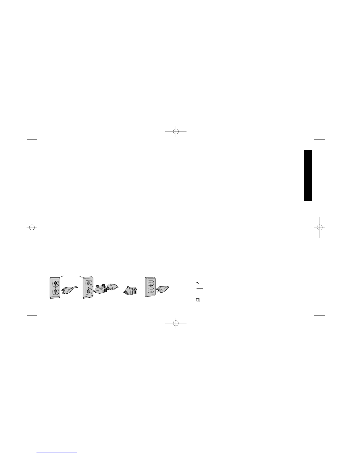
If your unit is intended for use on less than 150 volts, it has a plug
similar to that shown in Figure A. An adapter, Figures B and C, is
available for connecting Figure A plugs to two-prong receptacles.
The green-colored rigid ear, lug, etc., must be connected to a
permanent ground such as a properly grounded outlet box.
Whenever the adapter is used, it must be held in place by a metal
screw.
ADAPTER SHOWN IN FIGURES B and C IS NOT FOR USE IN
CANADA.
1
English
AB CD
GROUNDING PIN
GROUNDED
OUTLET
BOX
GROUNDING
MEANS
GROUNDING PIN
ADAPTER
PERSONAL SAFETY
• Stay alert, watch what you are doing and use common sense
when operating a power tool. Do not use tool while tired or
under the influence of drugs, alcohol, or medication. A moment
of inattention while operating power tools may result in serious
personal injury,
• Dress properly. Do not wear loose clothing or jewelry. Contain
long hair. Keep your hair, clothing, and gloves away from
moving parts. Loose clothing, jewelry, or long hair can be caught
in moving parts.
• Avoid accidental starting. Be sure switch is off before
plugging in. Carrying tools with your finger on the switch or
plugging in tools that have the switch on invites accidents.
• Remove adjusting keys or wrenches before turning the tool
on. A wrench or key that is left attached to a rotating part of the tool
may result in personal injury.
• Do not overreach. Keep proper footing and balance at all
times. Proper footing and balance enables better control of the tool
in unexpected situations.
• Use safety equipment. Always wear eye protection. Dust mask,
non-skid safety shoes, hard hat, or hearing protection must be used
for appropriate conditions.
• The label on your tool may include the following symbols.
V ................................volts
A ................................amperes
Hz ................................hertz
W....................................watts
min..................................minutes
....................................alternating current
................................direct current
n
o....................................no load speed
....................................Class II Construction
384621-01/DW866 1/8/02 2:27 PM Page 1
Page 5
• When servicing a tool, use only identical replacement parts.
Follow instructions in the Maintenance section of this manual.
Use of unauthorized parts or failure to follow Maintenance
Instructions may create a risk of electric shock or injury.
Additional Safety Instructions for
Cut-Off Machine
CAUTION: When cutting into walls, floors or wherever live
electrical wires may be encountered, DO NOT TOUCH ANY METAL
PARTS OF THE TOOL! Hold the tool only by insulated grasping
surfaces to prevent electric shock if you cut into a live wire.
• ALWA YS WEAR EYE PROTECTION WHEN USING THIS T OOL.
• Use of accessories not specified in this manual is not
2
…/min ..............revolutions or reciprocation per minute
....................earthing terminals
....................safety alert symbol
TOOL USE AND CARE
• Use clamps or other practical way to secure and support the
workpiece to a stable platform. Holding the work by hand or
against your body is unstable and may lead to loss of control.
• Do not force tool. Use the correct tool for your application. The
correct tool will do the job better and safer at the rate for which it is
designed.
• Do not use tool if switch does not turn it on or off. Any tool that
cannot be controlled with the switch is dangerous and must be
repaired.
• Disconnect the plug from the power source before making any
adjustments, changing accessories, or storing the tool. Such
preventative safety measures reduce the risk of starting the tool
accidentally.
• Store idle tools out of reach of children and other untrained
persons. T ools are dangerous in the hands of untrained users.
• Maintain tools with care. Keep cutting tools sharp and clean.
Properly maintained tools, with sharp cutting edges are less likely to
bind and are easier to control.
• Check for misalignment or binding of moving parts, breakage
of parts, and any other condition that may affect the tools
operation. If damaged, have the tool serviced before using.
Many accidents are caused by poorly maintained tools.
• Use only accessories that are recommended by the
manufacturer for your model. Accessories that may be suitable
for one tool, may become hazardous when used on another tool.
SERVICE
• Tool service must be performed only by qualified repair
personnel. Service or maintenance performed by unqualified
personnel could result in a risk of injury.
English
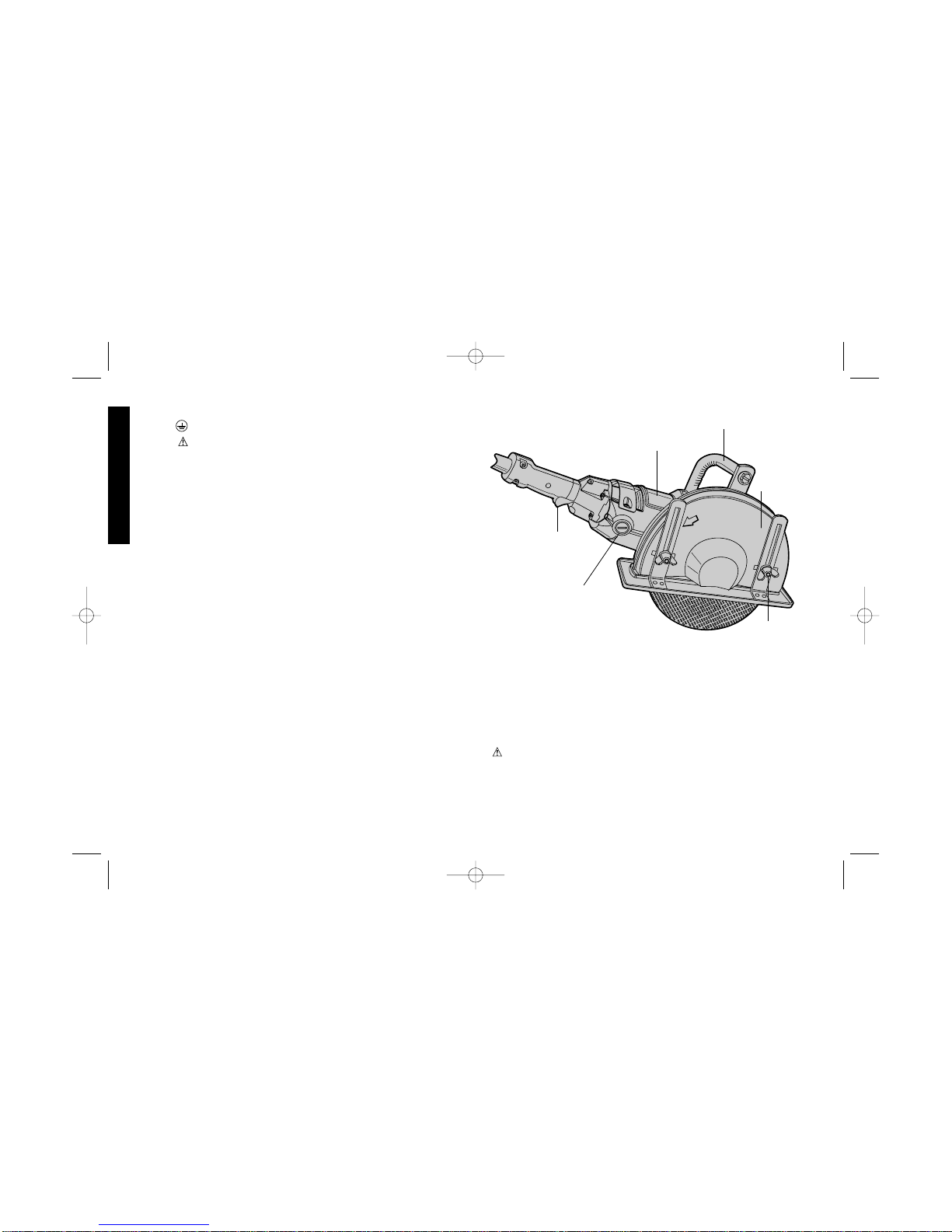
TRIGGER
SWITCH
BRUSH
CAP
FIELD
CASE
BAIL
HANDLE
GUARD
DEPTH
ADJUSTMENT
WING NUT
384621-01/DW866 1/8/02 2:27 PM Page 2
Page 6

recommended and may be hazardous. Use of power boostersthat
would cause the tool to be driven at speeds greater than its rated
speed constitutes misuse.
• Before attaching any wheel, check its manufacturer’s specifications and be sure that its safe operating speed is higher than
the no-load speed of the tool as shown on the nameplate.
• Before using, inspect each grinding wheel for cracks or flaws. If
such a crack or flaw is evident- discard the wheel. The wheel
should also be inspected whenever you think the tool may have
been dropped. Do not set unit down on wheel.
• When starting the tool (with a new or replacement wheel installed)
hold the tool in a well protected area. Never start the tool with a
person in line with the wheel. This includes the operator.
• In operation, avoid bouncing the wheel or giving it rough treatment.
If this occurs, stop the tool and inspect the wheel.
• Clean your tool out periodically.
• Protect personnel and combustible material in work area from
sparks generated by this tool.
SAVE THESE INSTRUCTIONS
Motor
Be sure your power supply agrees with the nameplate marking.
Voltage decrease of more than 10% will cause loss of power and
overheating. All D
EWalt tools are factory tested; if this tool does not
operate, check the power supply.
Controls (Figures 1 and 2)
CAUTION: Grasp tool firmly with both hands before attempting to
start.To start, grasp switch handle firmly and squeeze to depress
trigger. To stop tool, release trigger.
GUARD ADJUSTMENT: Disconnect tool from power supply and be
sure switch is in off position before adjusting guard. Guard may be
adjusted approximately 80˚ by loosening the guard adjustment knob.
3
English
Grasp the guard firmly and rotate to desired angle. Lock in position
by tightening the guard adjustment knob.
NOTE: The two guard mounting screws on each end of the clamp
should not be over-tightened, in order to allow the guard to rotate.
SPINDLE LOCK PIN is used to lock the spindle when changing
accessories. To engage the lock pin, disconnect the tool from the
power supply and be sure switch is in off position. Depress the lock
pin and turn the wheel and spindle until the lock pin engages the
spindle. Use wrench, supplied with the unit, to unscrew the spindle
nut and remove or mount accessories. Spindle and nut have right
hand threads.
NOTE: Slot in wrench handle may be used for additional leverage
when tightening or loosening wing nuts. Wrench is a standard part
furnished with the unit. Shoe can be adjusted to give a 4” maximum
depth of cut.
Operation
1. The tool is supplied with a cord and a 3-prong plug. Compare
voltage marked on nameplate of tool with that of your power supply
before plugging in tool. The voltages must be the same.
2. Before turning on tool, grasp both handles firmly and pick up tool.
Make sure nothing is near or in line with the wheel. Line up wheel
with material to be cut.
3. Turn on unit and feed wheel into work slowly, but with firm
pressure, while keeping the shoe firmly and squarely against the
work. Don not force the tool. For maximum efficiency and wheel
life, keep the wheel speed high.
Depth of Cut
The depth of cut can be adjusted by loosening the two wing nuts on
the outside of the guard. NOTE: The slot in handle of included
wrench may be used for additional leverage when loosening or
tightening the wing nuts.
384621-01/DW866 1/8/02 2:27 PM Page 3
Page 7
4
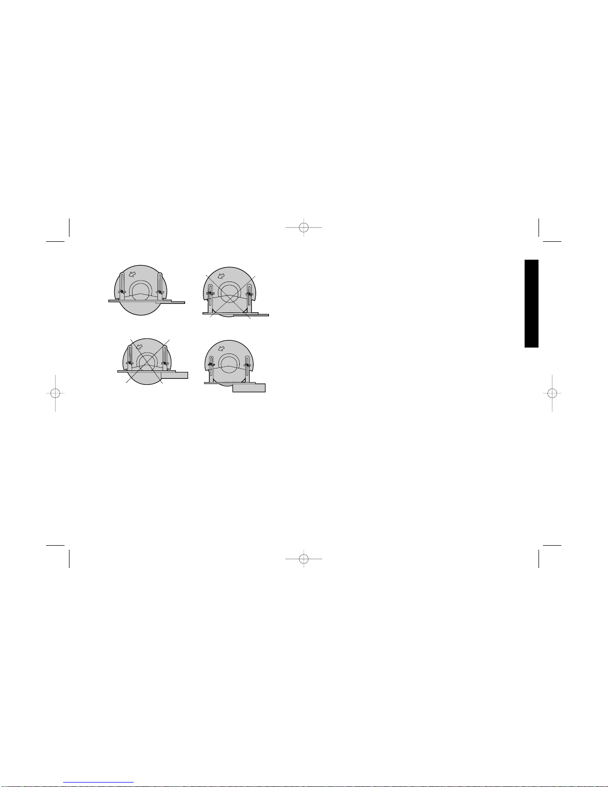
TO CUT METALS AND THIN MATERIALS
For minimum operator effort and greatest efficiency when cutting
metals and other thin materials, adjust shoe for maximum depth of
cut (Figure 3).
TO CUT STONE OR MASONRY MATERIALS
For maximum effectiveness, set the wheel exposure to about 1/2”
(13mm)beyond the shoe. For many applications, the material will
readily break along the 1/2” (13mm) deep scored line. If a deeper
cut is needed, increase the depth of cut in approximately 1/2” (13mm)
increments. See Figure 4.
Installing Abrasive Wheels (Figure 5)
1. TURN OFF TOOL AND DISCONNECT FROM POWER SUPPL Y.
2. Lay unit on a firm surface with bottom of shoe facing up.
3. Loosen shoe adjustment wing nuts, bring shoe up to minimum
cutting depth and tighten wing nuts. This step allows more
freedom in removing spindle nut and washers.
4. Using 1 1/8” (28mm) open end wrench (supplied with unit) remove
spindle nut, outer clamp washer and used wheel if one is installed.
Hold spindle from turning with spindle lock pin. Spindle threads
are right hand.
5. Select proper wheel, use only those approved accessories
specified in this manual. Never use wheels rated lower than
nameplate speed of unit.
6. Make sure inner clamp washer is in place and ears are engaged
with spindle flats. Slip wheel through bottom of shoe and slip
wheel over spindle. Be sure wheel goes over pilot diameter. of
inner clamp washer. Slip on outer clamp washer. Start threading
on spindle nut which will self align outer clamp washer. Engage
spindle lock pin and tighten nut with wrench. Do not over tighten
spindle nut.
7. Turn wheel by hand to make sure the wheel is properly centered,
that the wheel does not hit the shoe or guard and nut and that nut
and flanges are tight.
English
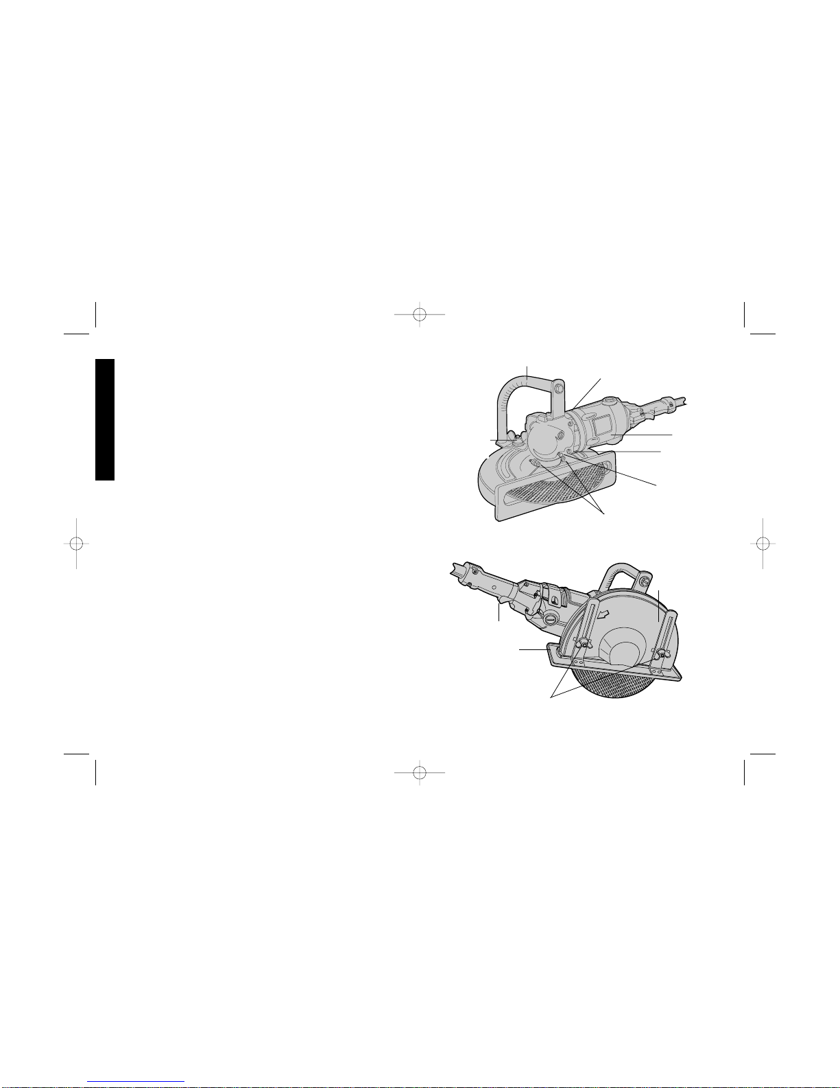
Figure 1
Figure 2
BAIL HANDLE
WEAR RING (GEAR CASE
COVER UNDERNEATH)
FIELD
SPINDLE
LOCK PIN
GUARD MOUNTING
SCREWS
GUARD
ADJUSTMEN
T KNOB
GEAR CASE
MOUNTING
SCREWS (4)
TRIGGER
SHOE
GUARD
DEPTH ADJUSTMENT
WING NUTS
384621-01/DW866 1/8/02 2:27 PM Page 4
Page 8
5
English
Figure 3
Figure 4
YES
NO
NO
YES
METALS OR THIN
MATERIAL
MASONRY
MATERIAL
Applications
1/8” (3mm) max. gauge sheet metal
concrete, cinder blocks and bricks
reinforcing rod- generally under 3/4” (19mm) diameter
1/8”(3mm) diameter concrete wire mesh
corrugated floor and ceiling form (concrete forms)
electrical conduit 1/8” (3mm) wall thickness
1/8” (3mm) max. thick structural forms such as channel, angles,
plate, etc.
NOTE: The cutting of materials heavier than those listed above are
not recommended due to the possibility of electrical overloading.
Conversion From Right Handed to Left
Handed
Operation
NOTE: This machine is assembled at the factory with the spindle on
right side of the unit for right handed operation.
1. TURN OFF TOOL AND DISCONNECT FROM POWER SUPPLY.
2. Place unit on a firm, flat work surface.
3. Remove brush caps and brushes.
4. Remove bail handle by removing guard adjusting knob and hex
bolt.
5. Remove the 4 gear case mounting screws.
6. Remove gear case.
7. Remove wear ring.
8. Pry the gear case cover, with armature attached, from field case.
The armature and gear case cover are one subassembly.
9. IMPORTANT:Notice a flat tab projecting from the gear case cover
and a corresponding recess in the gear case opposite the spindle.
Line up these two features and reassemble the gear case and
cover.
10. Replace the wear ring on the field case.
11.Rotate the field case and switch handle assembly 180˚. Then,
when viewing from the cord end, with the trigger switch down, the
spindle should be on the left side of the unit.
12. Replace the 4 gear case mounting screws.
13. Rotate the guard until the shoe faces in the same direction as the
switch guard. Be sure the guard is on the spindle bearing hub as
far as it will go and tighten guard mounting screws.
14. Replace the bail handle with the bolt and the guard adjusting knob.
15. Replace brushes and brush caps.
Accessories
Recommended accessories for use with your tool are available at
extra cost from your distributor or authorized service center.
384621-01/DW866 1/8/02 2:27 PM Page 5
Page 9

6
CAUTION: The use of any non-recommended accessory may be
hazardous.
Accessory Maximum Safe Speed
Masonry Wheel* 6300 RPM
(Silicon Carbide) 12” Dia. x 1/8” Thick x 1” Hole
Metal Cutting Wheel* 6300 RPM
(Aluminum Oxide) 12” Dia. x 1/8” Thick x 1” Hole
*Internally Reinforced
Cleaning
Blowing dust and grit out of the main housing by means of an air
hose is recommended and may be done as often as dirt is seen
collecting in and around the air vents. The motor should be running
while air is being blown into the vents.
Lubrication
Except for the needle roller bearings used at the upper end of the
spindle, closed-type, grease-sealed ball bearings are used
throughout. These bearings have sufficient lubrication packed in
them at the factory to last the life of the bearing. The needle bearings
mentioned above receive their lubrication from the grease in the gear
case.
Gears should be relubricated every 60 to 90 days, depending upon
use. This lubrication should only be attempted by experienced power
tool repair technicians like the mechanics at B&D service centers.
Brushes
Inspect carbon brushes often. Replace when brushes are worn down
to the identifying groove or when spring exerts insufficient pressure
to hold brush against commutator. Keep brushes clean and sliding
free in brass inserts.
English
Figure 5
SPINDLE NUT
ABRASIVE
WHEEL
OUTER
CLAMP
WASHER
INNER CLAMP
WASHER
WRENCH
SPINDLE
LOCK PIN
384621-01/DW866 1/8/02 2:27 PM Page 6
Page 10

7
English
TO REMOVE BRUSHES:
1. TURN OFF TOOL AND DISCONNECT FROM POWER SUPPLY.
2. Remove brush cap.
3. Pull brush assembly out of brass insert.
Motor Brushes
DEWALT uses an advanced brush system which automatically stops
the drill when the brushes wear out. This prevents serious damage to
the motor.
Maintenance
Use only mild soap and damp cloth to clean the tool. Never let any
liquid get inside the tool; never immerse any part of the tool into a
liquid.
Self-lubricating bearings are used in the tool and periodic
relubrication is not required. In the unlikely event that service is ever
needed, take your tool to an authorized service location.
Accessories
Recommended accessories for use with your tool are available at
extra cost from your distributor or local service center.
ACCESSORY MUST BE RATED FOR USE AT SPEED EQUAL TO
OR HIGHER THAN NAMEPLATE R.P.M. OF T OOL WITH WHICH IT
IS BEING USED.
If you need assistance in locating any accessory, please contact
D
EWALT Industrial Tool Company, 626 Hanover Pike, P.O. Box 158,
Hampstead, MD 21074 or call 1-800-4-D
EWALT (1-800-732-4441).
CAUTION: The use of any non-recommended accessory may be
hazardous.
Important
To assure product SAFETY and RELIABILITY, repairs, maintenance
and adjustment (including brush inspection and replacement) should
be performed by authorized service centers or other qualified service
organizations, always using identical replacement parts.
Full Warranty
DEWALT heavy duty industrial tools are warranted for one year from
date of purchase. We will repair, without charge, any defects due to
faulty materials or workmanship. For warranty repair information, call
1-800-4-D
EWALT. This warranty does not apply to accessories or
damage caused where repairs have been made or attempted by
others. This warranty gives you specific legal rights and you may have
other rights which vary in certain states or provinces.
In addition to the warranty, D
EWALT tools are covered by our:
30 DAY NO RISK SATISFACTION GUARANTEE
If you are not completely satisfied with the performance of your
DEWALTheavy duty industrial tool, simply return it to the participating
seller within 30 days for a full refund. Please return the complete unit,
transportation prepaid. Proof of purchase may be required.
384621-01/DW866 1/8/02 2:27 PM Page 7
Page 11

Importantes mesures de sécurité
• S’ASSURER QUE LES PROTECTEURS sont en place et en bon
état.
• BIEN DÉGAGER LA SURFACE DE TRAVAIL. Des surfaces et
des établis encombrés peuvent être la cause de blessures.
• TENIR COMPTE DU MILIEU DE TRAVAIL. Protéger les outils
électriques de la pluie. Ne pas s’en servir dans des endroits
humides ou mouillés. Bien éclairer la surface de travail.
• ÉLOIGNER LES ENFANTS. Tous les visiteurs doivent être tenus
à l’écart de l’aire de travail.
• RENDRE L’ATELIER SÛR POUR LES ENFANTS à l’aide de
cadenas, de disjoncteurs, ou en retirant les clés de mise en
tension.
• NE JAMAIS FORCER L’OUTIL. Afin d’obtenir un rendement sûr
et efficace, utiliser l’outil à son rendement nominal.
• UTILISER L’OUTIL APPROPRIÉ. Ne jamais exiger d’un petit outil
ou d’un accessoire le rendement d’un outil de fabrication plus
robuste.
• UTILISER DES CORDONS DE RALLONGE APPROPRIÉS.
S’assurer que le cordon de rallonge est en bon état. Lorsqu’on se
sert d’un cordon de rallonge, s’assurer qu’il est de calibre approprié
pour la tension nécessaire au fonctionnement de l’outil. L’utilisation
d’un cordon de calibre inférieur occasionne une baisse de tension
entraînant une perte de puissance et la surchauffe. Le tableau
suivant indique le calibre approprié selon la longueur du cordon et
les mentions de la plaque signalétique de l’outil. En cas de doute,
utiliser un cordon de calibre supérieur. Le chiffre indiquant le
calibre est inversement proportionnel au calibre du cordon.
• CORDONS DE RALLONGE POUR L’EXTÉRIEUR. Lorsque l’outil
sert à l’extérieur, utiliser seulement des cordons de rallonge prévus
à cet effet et portant la mention appropriée.
Calibre minimal des cordons de rallonge
Tension Longueur totale du cordon en pieds
120 V 0-25 26-50 51-100 101-150
240 V 0-50 51-100 101-200 201-300
Intensité (A)
Au Au Calibre moyen de fil (AWG)
moins plus
0-6 18161614
6 - 10 18 16 14 12
10-1216161412
12 - 16 14 12 Non recommandé
• PORTER DES VÊTEMENTS APPROPRIÉS. Éviter de porter des
vêtements amples, des gants, des cravates, des bagues, des
bracelets ou d’autres bijoux qui peuvent être happés par les pièces
en mouvement. Le port des chaussures à semelle antidérapante
est recommandé. Protéger la chevelure si elle est longue.
• TOUJOURS PORTER DES LUNETTES DE SÉCURITÉ. Porter
également un masque respiratoire si le travail de coupe produit de
la poussière. Des lunettes de correction de la vue standard
comportent seulement des verres résistant aux chocs; ce NE sont
PAS des lunettes de sécurité.
• NE PAS DÉPASSER SA PORTÉE. Toujours demeurer dans une
position stable et garder son équilibre.
• PRENDRE SOIN DES OUTILS. Conserver les outils propres et
affûtés pour qu’ils donnent un rendement supérieur et sûr. Suivre
les directives relatives à la remplacement des accessoires.
• DÉBRANCHER L’OUTIL avant de le réparer ou d’en changer un
accessoire (comme une lame, un foret ou un couteau).
• MINIMISER LES RISQUES DE DÉMARRAGES ACCIDENTELS.
S’assurer que l’interrupteur est en position hors tension avant de
brancher l’outil.
• UTILISER LES ACCESSOIRES RECOMMANDÉS. Consulter le
guide d’utilisation afin de connaître les accessoires recommandés.
L’utilisation d’accessoires inappropriés présente des risques de
blessures.
8
Français
384621-01/DW866 1/8/02 2:27 PM Page 8
Page 12

Réparer ou remplacer immédiatement les cordons endommagés ou
usés.
L ‘outil est conçu pour être branché sur un circuit dont les prises
ressemblent à celle illustrée à la figure A. L’outil comporte une fiche
de terre qui ressemble à celle illustrée à la figure A. On peut se servir
d’un adaptateur temporaire (comme celui des figures B et C) pour
brancher la fiche dans une prise à 2 orifices (fig. B) lorsqu’il n’y a
pas de prise mise à la terre. Il faut seulement se servir de
l’adaptateur temporaire jusqu’à ce qu’un électricien certifié puisse
installer une prise mise à la terre appropriée. Il faut alors relier l’oreille
rigide, la cosse ou tout autre objet du genre de couleur verte à une
mise à la terre permanente (comme à la boîte d’une prise bien mise
à la terre).
Mesures de sécurité additionnelles
relatives aux machines à tronçonner
MISE EN GARDE : Lorsqu’on coupe dans les murs, les planchers
ou tout autre endroit o∫ peuvent se trouver des fils sous tension,
NE PAS TOUCHER ÀTOUT COMPOSANT MÉTALLIQUE DE
L’OUTIL. Ne le saisir que par ses surfaces de prise isolées afin de se
protéger des secousses électriques.
• TOUJOURS PORTER DES LUNETTES DE SÉCURITÉ
LORSQU’ON SE SERT DE L’OUTIL.
• L’utilisation d’accessoires non mentionnés dans le présent guide
9
Français
• NE JAMAIS SE TENIR SUR L’OUTIL. Cela présente des risques
de blessures graves si l’outil bascule ou si on touche à la lame par
inadvertance.
• VÉRIFIER LES PIÈCES ENDOMMAGÉES. Avant de continuer à
utiliser l’outil, il faut vérifier si le protecteur ou toute autre pièce
endommagée remplit bien la fonction pour laquelle il a été prévu.
Vérifier l’alignement et les attaches des pièces mobiles, le degré
d’usure des pièces et leur montage, ainsi que tout autre facteur
susceptible de nuire au bon fonctionnement de l’outil. Il faut réparer
ou remplacer tout protecteur ou autre composant endommagé.
• NE JAMAIS LAISSER UN OUTIL EN MARCHE SANS
SURVEILLANCE. LE METTRE HORS TENSION. Ne pas laisser
l’outil avant l’immobilisation complète de la lame.
Mise à la terre
En cas de mauvais fonctionnement ou de bris de l’outil, la mise à la
terre procure un chemin de moindre résistance au courant électrique
afin de minimiser les risques de secousses électriques. Le cordon de
l’outil comporte un conducteur de terre et une fiche de mise à la terre.
La fiche doit être branchée dans une prise de machine bien installée
et mise à la terre conformément aux lois et règlements locaux. Ne
pas modifier la fiche fournie. Lorsque la fiche n’entre pas dans la
prise, demander à un électricien qualifié d’installer une prise
appropriée.
La mauvaise connexion du conducteur de terre de l’outil présente
des risques de secousses électriques. Le conducteur dont l’isolant
est vert ou vert avec des lignes jaunes constitue la mise à la terre. En
cas de réparation ou de remplacement du cordon ou de la fiche, ne
pas relier le conducteur de terre à une borne sous tension.
Consulter un électricien qualifié ou le personnel des centres de
service an cas d’incompréhension des instructions relatives à la mise
à la terre ou en cas de doute quant à la mise à la terre de l’outil.
Utiliser seulement des cordons de rallonge trifilaires dotés de fiche
mise à la terre à trois broches, ainsi que des prises à 3 orifices
acceptant la fiche de l’outil.
AB C
BROCHE DE PRISE
MISE À LA TERRE
PRISE MISE
À LA TERRE
DISPOSITIF DE
MISE À LA TERRE
ADAPTATEUR
384621-01/DW866 1/8/02 2:27 PM Page 9
Page 13

10
Français
INTERRUPTEUR
À DÉTENTE
COUVERCLE DES
BALAIS
BOÎTER
DU CHAMP
POIGNÉECONTOUR
PROTECTEUR
ÉCROU À OREILLES
DU RÉGLAGE DE LA
PROFONDEUR
Commandes (Figures 1 et 2)
MISE EN GARDE : Saisir fermement l’outil des deux mains avant
de le mettre en marche. Pour l’actionner, bien saisir la poignée de
l’interrupteur et l’écraser afin d’enfoncer la détente. Pour arrêter
l’outil, relâcher la détente.
RÉGLAGE DU PROTECTEUR : Débrancher l’outil et s’assurer que
l’interrupteur est à la position hors tension avant de régler le
protecteur. On peut régler le protecteur d’environ 80¡ en desserrant
le bouton de réglage du protecteur. Saisir fermement le protecteur et
le faire tourner à l’angle voulu. Verrouiller en place en serrant le
bouton de réglage du protecteur. NOTE: Il ne faut pas trop serrer les
deux vis de montage du protecteur à chaque extrémité de la bride
afin de permettre au protecteur de tourner.
n’est pas recommandé et peut être dangereuse. L’utilisation de
dispositifs de suralimentation permettant de faire fonctionner l’outil
plus vite que sa vitesse nominale constitue une mauvaise
utilisation.
• Avant d’installer une meule, en vérifier les spécifications du
fabricant et s’assurer la vitesse nominale de la meule est
supérieure à la vitesse sous vide indiquée sur la plaque
signalétique de l’outil.
• Avant d’utiliser une meule, s’assurer qu’elle n’est ni craquée, ni
fêlée. Le cas échéant, jeter la meule. Il faut également inspecter
la meule lorsqu’on pense que l’outil est tombé. Ne pas déposer
l’outil sur la meule.
• Lorsqu’on démarre l’outil (aprés avoir installé une nouvelle meule),
le saisir dans un endroit bien protégé. Ne jamais mettre l’outil en
marche lorsque quelqu’un se tient devant la meule (y compris
l’utilisateur).
• Lors de l’utilisation, éviter de faire sauter la meule ou de la
maltraiter. Le cas échéant, arrêter l’outil et vérifier la meule.
• Nettoyer l’outil régulièrement.
• Protéger les objets personnels combustibles de la zone de travail
des étincelles que produit l’outil.
CONSERVER CES MESURES.
Moteur
Veiller à ce que la tension d’alimentation soit conforme aux exigences de la
plaque signalétique de l’outil. Une baisse de tension de plus de 10 p. 100
entra”ne une perte de puissance et la surchauffe. Tous les outils DEWALT
sont essayés avant de quitter l’usine. Lorsque celui-ci refuse de fonctionner,
vérifier la source de courant électrique.
384621-01/DW866 1/8/02 2:27 PM Page 10
Page 14

LA TIGE DE VERROUILLAGE DE L’ARBRE sert lors du
remplacement des accessoires. Pour l’engager, débrancher l’outil et
s’assurer que l’interrupteur est à la position hors tension. Enfoncer
la tige de verrouillage et faire tourner la meule et l’arbre jusqu’à ce
que la tige de verrouillage s’engage dans l’arbre. Se servir de la clé
fournie pour dévisser l’écrou de l’arbre, puis retirer ou installer des
accessoires. L’arbre et l’écrou ont des filets à droite.
NOTE : La fente dans la poignée de la clé peut servir de levier
lorsqu’on serre ou qu’on desserre les écrous ˆ oreilles. La clé est
comprise dans l’emballage. On peut régler le patin afin d’obtenir une
profondeur de coupe maximale de 100 mm (4 po).
Fonctionnement
1. L’outil comprend un cordon et une fiche à3 broches. Comparer la
tension indiquée sur la plaque signalétique de l’outil à celle
d’alimentation avant de brancher l’outil. Les tensions doivent être
identiques.
2. Avant de mettre l’outil en marche, bien saisir les deux poignées et
soulever l’outil. S’assurer qu’il n’y a rien à proximité ni devant la
meule. Aligner la meule sur le matériau à découper.
3. Mettre l’outil en marche et faire avancer lentement la meule dans
le matériau, en y exerçant une pression ferme, tout en maintenant
le patin à plat contre le matériau. Éviter de forcer l’outil. Afin de
maximiser le rendement et la durée de l’outil, utiliser l’outil à sa
vitesse nominale.
Profondeur de coupe
On peut régler la profondeur de coupe en desserrant les deux écrous
à oreilles qui se trouvent sur la face extérieure du protecteur..
NOTE : La fente dans la poignée de la clé fournie peut servir de
levier lorsqu’on serre ou qu’on desserre les écrous à oreilles.
COUPE DE MÉTAUX ET DE MATÉRIAUX MINCES
Afin de minimiser les efforts de l’utilisateur et optimiser l’efficacité de
l’outil lors de la coupe de m≥taux ou de mat≥riaux minces, r≥gler le
11
Français
Figure 1
Figure 2
POIGNÉE-CONTOUR
BAQUE D´USURE (OUVERCLE
DU BOÎTIER DES ENGRENAGES
SOUS LA BAGUE)
BOÎTIER DU
CHAMP
TIGE DE
VERROUILLAGE
DE LARBRE
VIS DE MONTAGE
DU PROTECTEUR
BOUTON DE
RÉGLAGE DU
PROTECTEUR
VIS DE MONTAGE
DU BOÎTIER DES
ENGRENAGES (4)
INTERRUPTEUR
À DÉTENTE
PATIN
PROTECTEUR
ÉCROUS À OREILLES DU
RÉGLAGE DE LA PROFONDEUR
384621-01/DW866 1/8/02 2:27 PM Page 11
Page 15

12
7. Faire tourner la meule ˆ la main afin de s’assurer que la meule
est bien centr≥e, qu’elle ne frappa pas le patin ni le protecteur et
l’≥crou, et que les brides et l’≥crou sont serr≥s.
Utilisations
tôle d’une épaisseur maximale de 3 mm (1/8 po)
béton, blocs de cendre et brique
barre d’armature - habituellement d’un diamètre de moins de 19 mm
(3/4 po)
treillis métallique d’un diamètre de 3 mm (1/8 po)
plancher ondulé et coffrage de plafond (coffrages de béton)
conduit électrique à gaine de 3 mm (1/8 po)
profilés d’une épaisseur maximale de 3 mm (1/8 po) comme des
Français
Figure 3
Figure 4
OUI
NON
NON
OUI
MÉTAUX OU
MATÉRIAU
MINCE
MAÇONNERIE
patin ˆ la profondeur de coupe maximale (fig. 3).
COUPE DE PIERRE OU DE MA≤ONNERIE
Afin de maximiser l’efficacité de l’outil, régler l’ouverture de la meule
à environ 13 mm (1/2 po) au-delà du patin. Dans de nombreux cas,
le matériau se brise aisément le longe du trait gravé de 13 mm
(1/2 po) de profondeur. Lorsque la coupe doit être plus profonde,
augmenter la profondeur de coupe en multiples de 13 mm (1/2 po)
(fig. 4).
Installation de la meule (Figure 5)
1. METTRE L’OUTIL HORS TENSION ET LE DÉBRANCHER.
2. Déposer l’outil sur une surface ferme avec le dessous du patin
vers le haut.
3. Desserrer les écrous à oreilles du réglage du patin, soulever le
patin à la profondeur de coupe minimale et serrer les écrous
à oreilles. On facilite de la sorte le retrait de l’écrou et des
rondelles de l’arbre.
4. Utiliser la clé à fourche de 28 mm (1 1/8 po) fournie pour retirer
l’écrou de l’arbre, la rondelle de fixation externe et la meule usée
(le cas échéant). Empêcher l’arbre de tourner à l’aide de la tige
de verrouillage. Les filets de l’arbre sont à droite.
5. Choisir la meule appropriée, utiliser seulement un des
accessoires spécifés dans le présent guide. Ne jamais utiliser des
meules dont la vitesse nominale est inférieure à celle de l’outil.
6. S’assurer que la rondelle de fixation interne est en place et que
les oreilles sont engagées sur les côtés plats de l’arbre. Faire
glisser la meule sous le patin et sur l’arbre. S’assurer que la
meule passe par-dessus le diamètre du guide de la rondelle de
fixation interne. La faire glisser sur la rondelle de fixation externe.
La fileter sur l’écrou de l’arbre ce qui permet le centrage
automatique de la rondelle de fixation externe. Engager la tige de
verrouillage de l’arbre et serrer l’écrou à l’aide de la clé. Éviter
de trop serrer l’≥crou de l’arbre.
384621-01/DW866 1/8/02 2:27 PM Page 12
Page 16

poutres en U, des cornières et des plaques
NOTE : Il n’est pas conseillé de couper des matériaux plus épais que
ceux mentionnés en raison d’une éventuelle surcharge électrique
de l’outil.
Conversion de l’outil pour les droitiers ou
les gauchers
Fonctionnement
NOTE : En usine, l’arbre est installé du côté droit de l’outil pour les
droitiers.
1. METTRE L’OUTIL HORS TENSION ET LE DÉBRANCHER.
2. Déposer l’outil sur une surface solide et plane.
3. Retirer les couvercles des balais et les balais.
4. Retirer la poignée-contour en enlevant le bouton de réglage du
protecteur et le boulon hexagonal.
5. Retirer les quatre vis de montage du boîtier des engrenages.
6. Retirer le boîtier des engrenages.
7. Retirer la bague d’usure.
8. Soulever le couvercle du boîtier des engrenages du boîtier du
champ avec l’induit fixé. Le couvercle du boîtier des engrenages
et l’induit forment un sous-assemblage.
9. IMPORTANT: Remarquer l’ergot plat du couvercle du boîtier des
engrenages et le creux correspondant du boîtier des engrenages
à l’opposé de l’arbre. Aligner ces deux éléments et remonter le
boîtier des engrenages et le couvercle.
10. Remettre la bague d’usure sur le boîtier du champ.
11.Faire tourner le boîtier du champ et la poignée de l’interrupteur
sur 180¡. Ensuite, lorsqu’on se place à l’extrémité o∫ se trouve le
cordon et avec l’interrupteur à détente vers le bas, l’arbre devrait
se trouver du côté gauche de l’outil.
12. Remettre les quatre vis de montage du boîtier des engrenages.
13. Faire tourner le protecteur jusqu’à ce que le patin soit dans le
même sens que le protecteur de l’interrupteur. S’assurer que le
13
Français
Figure 5
ÉCROU DE
L´ARBRE
MEULE
ABRASIVE
RONDELLE DE
FIXATION
EXTERNE
RONDELLE DE
FIXATION
INTERNE
CLÉ
TIGE DE VERROUILLAGE
DE L´ARBRE
384621-01/DW866 1/8/02 2:27 PM Page 13
Page 17

14
Il faut lubrifier les engrenages entre 60 et 90 jours, selon l’utilisation
de l’outil. Confier cette lubrification seulement au personnel
qualifiéd’un centre de service autorisé.
Balais
Vérifier souvent les balais au carbone. Les remplacer lorsqu’ils sont
usés jusqu’à la rainure d’identité ou lorsque le ressort n’exerce plus
la pression suffisante pour maintenir le balai contre le commutateur.
S’assurer que les balais sont propres et qu’ils glissent librement dans
les pièces rapportés de laiton.
Faire ce qui suit pour retirer les balais.
1. METTRE L’OUTIL HORS TENSION ET LE DÉBRANCHER.
2. Retirer le couvercle des balais.
3. Tirer le balai hors de la pièce rapportée de laiton.
IImportant
Pour assurer la SÉCURITÉ D’EMPLOI et la FIABILITÉ de l’outil, n’en
confier la réparation, l’entretien et les rajustements (y compris
l’inspection et le remplacement des balais) qu’au personnel d’un
centre de service D
EWALT ou d’un atelier d’entretien autorisé
n’utilisant que des pièces de rechange identiques.
Garantie complète
Les outils industriels de service intensif D
EWALT sont garantis
pendant un an à partir de la date d’achat. Toute pièce d’un outil
D
EWALT qui s’avérait défectueuse en raison d’un vice de matière ou
de fabrication sera réparée ou remplacée sans frais. Pour obtenir de
plus amples renseignements sur les réparations couvertes par la
garantie, composer le 1 (800) 4-D
EWALT (! (800) 433-9258). La ga
rantie ne couvre pas les accessories ni les réparations tentées ou
effectuées par des tiers. Les modalités de la présente garantie
donnent des droits légaux spécifiques. L’utilisateur peut également
se prévaloir d’autres droits selon l’état ou la province qu’il habite.
Français
protecteur soit à fond sur le moyeu de soutien de l’arbre et serrer
les vis de montage du protecteur.
14. Remettre la poignée-contour en place à l’aide du boulon et du
bouton de réglage du protecteur.
15. Remettre en place les balais et les couvercles des balais.
Accessoires
Les accessoires recommandés sont vendus séparément au centre
de service de la région.
MISE EN GARDE : L’utilisation de tout accessoire non
recommandé peut être dangereuse.
Accessoire Vitesse nominale
Meule pour maéonnerie* 6 300 trs/min
(carbure de silicium) Diam. de 304 mm (12 po), épaiss. de
4 mm (1/8 po) et trou de 25 mm (1 po)
Meule pour métaux* 6 300 trs/min
(oxyde d’aluminium) Diam. de 304 mm (12 po), épaiss. de
4 mm (1/8 po) et trou de 25 mm (1 po)
*Armature interne
Nettoyage
Il est conseilé d’utiliser un boyau d’air pour souffler la poussière et les
saletés hors du bo”tier de l’outil. On peut souffler de l’air dès que les
saletés s’accumulent dans les évents du ventilateur et autour de
ceux-ci. Le moteur devrait fonctionner lorsqu’on souffle de l’air dans
les évents.
Lubrification
À l’exception des roulements à rouleaux et à aiguilles utilisés
àl’extrémité supérieure de l’arbre, l’outil comporte des roulements
scellés et lubrifiés. Ces derniers renferment suffisamment de graisse
pour la durée du roulement. Les roulements à aiguilles sont lubrifiés
par la graisse du bo”tier des engrenages.
384621-01/DW866 1/8/02 2:27 PM Page 14
Page 18

En outre, la garantie suivante couvre les outils DEWALT.
GARANTIE DE SATISFACTION DE 30 JOURS OU ARGENT REMIS
Si, pour quelque raison que ce soit, l’outil industriel de service intensif
D
EWALT ne donne pas entière satisfaction, il suffit de le retourner
chez le marchand participant dans les 30 jours suivant la date
d’achat afin d’obtenir un remboursement complet. Il faut retourner,
port payé, l’outil complet. On peut exiger une preuve d’achat.
15
Français
384621-01/DW866 1/8/02 2:27 PM Page 15
Page 19

16
Español
Instrucciones importantes de seguridad
ADVERTENCIA: Es indispensable sujetarse a las precauciones
básicas de seguridad, con la finalidad de reducir el peligro de
incendio, choque eléctrico y lesiones personales, en todas las
ocasiones en que se utilicen herramientas eléctricas. Entre estas
precauciones se incluyen las siguientes.
LEA TODAS LAS INSTRUCCIONES
Instrucciones de conexión a tierra
En el caso de mal funcionamiento, la tierra proporciona una vía de
menor resistencia a la corriente eléctrica para reducir el riesgo de
choque eléctrico. Esta herramienta está equipada con un cable
eléctrico con un conductor a tierra y pata de aterrizaje. La clavija debe
conectarse a una toma de corriente instalada correctamente y
aterrizada de conformidad con todos los reglamentos locales. No
modifique la clavija, si no se ajusta a la toma de corriente, haga que
un electricista calificado le instale una toma adecuada.
La conexión incorrecta del conductor a tierra del equipo puede
originar riesgos de choque eléctrico. El conductor cuyo aislamiento es
de color verde con o sin franjas amarillas es el conductor a tierra del
equipo. Si se requiere reparación o cambio del cable eléctrico o la
clavija, no conecte el conductor a tierra a una terminal viva.
Consulte con un electricista si no comprende perfectamente las
instrucciones de aterrizaje, o si tiene dudas acerca de la conexión a
tierra de su equipo.
Utilice solamente extensiones de tres cables que tengan clavijas de
tres patas y tomas de corriente de tres polos que acepten la clavija de
la herramienta.
Repare o reemplace inmediatamente los cables dañados o
desgastados.
Esta herramienta está diseñada para utilizarse en circuitos que
tengan una toma de corriente similar a la ilustrada en la figura A. Se
INTERRUPTOR
DE GATILLO
TAPA DE
CARBONES
CAJA DEL CAMPO
MANGO EN ARCO
GUARDA
MARIPOSA DE AJUSTE
GUARDA
Epecificaciones
Tensión de alimentación 120 V CA/CD
Potencia nominal: 500 W
Frecuencia de operación: 50/60 Hz
Consumo de corriente: 15 A
384621-01/DW866 1/8/02 2:27 PM Page 16
Page 20

17
Español
puede utilizar un adaptador temporal, que se parece al mostrado en
las figuras B y C, para conectar esta clavija a una toma de corriente
de dos polos como se observa en la figura B si no dispone de una
toma aterrizada. Solamente debe utilizar el adaptador temporal hasta
que un electricista le instale una toma apropiada.
La oreja, lengüeta, o similar de color verde que se extiende del
adaptador debe conectarse a tierra permanente, como una toma de
corriente aterrizada.
Instrucciones importantes de seguridad
• CONSERVE LAS GUARDAS EN SU SITIO y listas para trabajar.
• CONSERVE LIMPIA EL AREA DE TRABAJO. Las áreas y bancos
con objetos acumulados en desorden propician los accidentes.
• NO SE EMPLEE EN AMBIENTES PELIGROSOS. No utilice
herramientas eléctricas en ligares inundados o mojados, ni las
exponga a la lluvia. Conserve bien iluminada el área de trabajo.
• CONSERVE APARTADOS A LOS NIÑOS. Todos los visitantes
deben permanencer a distancia segura de la zona de trabajo.
• HAGA SU TALLER A PRUEBA DE NIÑOS con candados,
interruptores maestros y retirando las llaves de encendido.
• NO FUERCE LA HERRAMIENTA. Esta cumplirá mejor con su
trabajo y de manera más segura bajo las especificaciones para las
que se diseñó.
• EMPLEE LA HERRAMIENTA ADECUADA. No fuerce una
herramienta o sus dispositivos en una tarea para los que no han
sido diseñados.
• UTILICE UN CABLE DE EXTENSION ADECUADO. Asegúrese
que su extensión esté en buenas condiciones. Cuando utilice una
extensión, asegúrese de emplear una que soporte la corriente que
su herramienta necesita. Una extensión con calibre insuficiente
provocará una caída en el voltaje de la línea, ocasionando pérdida
de potencia y sobrecalentamiento. El cuadro siguiente muestra el
calibre correcto a utilizarse de acuerdo con la longitud y el
amperaje indicado en la placa de identificación. Si tiene dudas,
utilice el calibrte siguiente. Mientras más pequeño sea el número
del calibre, mayor será su capacidad.
Calibre mínimo para cordones de extensión
Volts Longitud total del cordón en metros
120V 0-7,6 7,6-15,2 15,2-30,4 30,4-45,7
240V 0-15,2 15,2-30,4 30,4-60,9 60,9-91,4
AMPERAJE
Más No más Calibre del cordón AWG
de de
0-6 18161614
6 - 10 18 16 14 12
10-1216161412
12 - 16- 14 12 No recomendado
• CORDONES DE EXTENSION PARA INTEMPERIE. Cuando
utilice la herramienta a la intemperie, solamente utilice extensiones
diseñadas para ello y así marcadas.
• VISTA LAS PRENDAS ADECUADAS. No utilice prendas de
vestir flojas, guantes, corbatas, anillos, brazaletes ni otras piezas
de joyería que pudiesen quedar atrapadas en las partes móviles.
Se recomienda el empleo de calzado antiderrapante. Cúbrase el
cabello si lo tiene largo.
• SIEMPRE UTILICE GAFAS DE SEGURIDAD. También utilice una
máscara contra polvo si la operación a efectuar lo produce. Los
anteojos de uso diario solamente tienen lentes resistentes al
impacto, NO SON anteojos de seguridad.
• NO SE SOBREEXTIENDA. Conserve siempre bien apoyados los
pies, lo mismo que el equilibrio.
AB C
PATA DE
CONEXION A
TIERRA
TOMA DE
CORRIENTE
ATERRIZADA
MEDIO DE
ATERRIZAJE
ADAPTADOR
384621-01/DW866 1/8/02 2:27 PM Page 17
Page 21

• CUIDE SUS HERRAMIENTAS. Conserve sus herramientas
afiladas y limpias para que funcionen mejor y de manera más
segura. Siga las instrucciones de cambio de accesorios.
• DESCONECTE LA HERRAMIENTAS antes de efectuarles
servicio y cuando les cambie acesorios, como cuchillas, brocas y
similares.
• REDUZCA EL RIESGO DE ENCENDIDO ACCIDENTAL.
Asegúrese que el interruptor esté en posición de apagado antes
de conectar la herramienta.
• UTILICE LOS ACCESORIOS RECOMENDADOS. Busque en el
manual de instrucciones los accesorios recomendados. El uso de
accesorios inadecuados puede causar riesgos de lesiones.
• NUNCA SE PARE EN LA HERRAMIENTA. Puede provocarse
lesiones graves si la herramienta se vuelca o si hace contacto
accidental con la herramienta de corte.
• REVISE LAS PARTES DAÑADAS. Antes de seguir utilizando la
herramienta, debe revisar cuidadosamente una guarda o cualquier
otra pieza que esté dañada para determinar si cumplirá
adecuadamente con su función; revise la alineación de las piezas
móviles, sus montajes, ruptura de partes y cualesquiera otras
condiciones que pudiesen afectar su operación. Repare o
reemplace las piezas dañadas.
• NUNCA DEJE LA HERRAMIENTA EN FUNCIONAMIENTO Y
DESATENDIDA. APAGUELA. No deje la herramienta hasta que
se haya detenido por completo.
Instrucciones adicionales de seguridad
para la máquina cortadora
PRECAUCION: Cuando emplee esta herramienta para el corte
sobre paredes, pisos u otras zonas en las que puedan encontrarse
cables eléctricos “vivos”, ¡NO TOQUE NINGUNA PARTE
METÁLICA DE LA MISMA! Sostenga la herramienta sólo por las
superficies de sujeción aislantes para evitar el choque eléctrico si la
segueta entrara en contacto con un cable “vivo”.
18
Español
Figura 1
Figura 2
MANGO EN ARCO
ANILLO DE DESGASTE (TAPA DE
CAJA DE ENGRANES DEBAJO)
CAJA DEL
CAMPO
PERNO DE
SEGURO DE LA
FLECHA
TORNILLOS DE MONTAJE DE
LA GUARDA
PERILLA DE
AJUSTE DE
LA GUARDA
TORNILLOS DE
MONTAJE DE LA CAJA
DE ENGRANES (4)
GATILLO
ZAPATA
GUARDA
MARIPOSAS DE AJUSTE DE
PROFUNDIDAD
384621-01/DW866 1/8/02 2:27 PM Page 18
Page 22

• SIEMPRE UTILICE ANTEOJOS DE SEGURIDAD CUANDO
EMPLEE ESTA HERRAMIENTA.
• No se recomienda el empleo de accesorios no especificados en
este manual. El uso de amplificadores de potencia que permitan
que la herramienta funcione a mayor velocidad que la especificada
constituye mal uso.
• Antes de instalar cualquier disco, verifique las especificaciones del
fabricante y cerciórese que la velocidad de operación segura es
mayor que la velocidad sin carga especificada en la placa de
identificación de la herramienta.
• Antes de usar la unidad, revise los discos de corte en busca de
cuarteaduras. Si hay cuarteaduras, deseche el disco. También
debe revisarse el disco si usted piensa que se ha golpeado. Nunca
deje la unidad apoyada sobre el disco.
19
Español
Figura 3
Figura 4
SI
NO
NO
SI
METALES O
MATERIAL
DELGADO
MATERIAL DE
MAMPOSTERIA
• Cuando encienda la herramienta (con un disco nuevo, o después
de haberlo cambiado), colóquela en un área protegida. Si el disco
se cuartea, puede estallar en menos de un minuto. Nunca
encienda la unidad si hay personas en línea con la herramienta,
incluyendo al operador.
• Durante la operación, evite que el disco rebote. Si esto ocurre,
detenga la unidad y revise el disco.
• Limpie su cortadora periódicamente.
• Proteja a personal y material combustible que se encuentren en
el área de trabajo de las chispas generadas por esta herramienta.
CONSERVE ESTAS
INSTRUCCIONES
Motor
Asegúrese que su alimentación de corriente concuerde con la
marcada en la placa de identificación de la herramienta.
Disminuciones en el voltaje mayores a 10% causarán pérdida de
potencia y sobrecalentamiento. Todas las herramientas DeWALT se
prueban en la fábrica; si esta herramienta no funciona, revise la
alimentación de corriente.
Controles (figuras 1 y 2)
PRECAUCION: Sujete la herramienta firmemente con ambas
manos antes de intentar encenderla. Para encenderla, sujete el
mango del interruptor con firmeza y oprima el gatillo.
AJUSTE DE LA GUARDA: Desconecte la herramienta de la toma
de corriente y asegúrese que el interruptor esté en posición de
apagado antes de ajustar la guarda. La guarda se puede ajustar
aproximadamente 80° aflojando la perilla de ajuste. Tome la guarda
con firmeza y gírela hasta el ángulo que desee. Asegúrela en
posición apretando la perilla de ajuste. NOTA: No deben
sobreapretarse los dos tornillos de montaje de la guarda que se
384621-01/DW866 1/8/02 2:27 PM Page 19
Page 23

20
Español
PARA CORTAR METALES Y MATERIALES DELGADOS
Para que el operador haga esfuerzo mínimo y obtenga la mayor
eficiencia al cortar metales y otros materiales delgados, ajuste la
zapata para la máxima profundidad de corte (figura 3).
PARA CORTAR PIEDRA Y MATERIALES DE ALBAÑILERIA
Para obtener la máxima efectividad, ajuste la exposición del disco a
aproximadamente 13 mm (1/2”) por debajo de la zapata. En muchas
aplicaciones, el material se romperá con la línea de corte a 13 mm
(1/2”), si llegase a requerir mayor profundidad, auméntela en
incrementos de aproximadamente 13 mm (1/2”). Observe la figura 4.
Instalación de los discos abrasivos
(figura 5)
1. APAGUE Y DESCONECTE LA HERRAMIENTA DE LA TOMA
DE CORRIENTE.
2. Deje la unidad sobre una superficie firme con la parte inferior de
la zapata apuntando hacia arriba.
3. Afloje las mariposas de ajuste de la zapata, lleve la zapata hasta
la profundidad mínima de corte y apriete las mariposas. Este paso
le permite mayor libertad para quitar la tuerca de la flecha y las
roldanas.
4. Afloje la tuerca de la flecha con la llave de 28 mm (1 1/8”)
(suministrada con la unidad), quite la roldana y el disco usado, si
es que hay uno instalado. Evite que la flecha gire por medio del
seguro. La cuerda de la flecha es derecha.
5. Seleccione el disco apropiado; utilice únicamente los accesorios
especificados en este manual. Nunca utilice discos para
velocidades inferiores a la señalada en la placa de identificación
de la unidad.
6. Asegúrese que la roldana de sujeción interior esté en su sitio y
que las orejas estén enganchadas con los planos de la flecha.
Deslice el disco a través de la parte inferior de la zapata y sobre
la flecha. Asegúrese que el disco quede sobre el diámetro piloto
Figura 5
TUERCA DE
LA FLECHA
DISCO
ABRASIVO
ROLDANA DE
SUJECION
EXTERIOR
ROLDANA DE
SUJECION
INTERIOR
LLAVE
PERNO DE
SEGURO DE LA
FLECHA
384621-01/DW866 1/8/02 2:27 PM Page 20
Page 24

encuentran en cada extremo del soporte, para permitir que la guarda
gire.
EL PERNO DE SEGURO DE LA FLECHA se utiliza para fijar la
flecha para cambiar accesorios. Para accionar el seguro, desconecte
la herramienta de la toma de corriente y asegúrese que el interruptor
esté en posición de apagado. Oprima el perno del seguro y gire el
disco y la flecha hasta que el perno se enganche. Utilice la llave
suministrada con la unidad para destornillar la tuerca y desmontar o
instalar accesorios. La flecha y la tuerca tienen cuerda derecha.
NOTA: La ranura del mango de la llave se puede utilizar para hacer
palanca adicional al apretar o aflojar las mariposas. La llave es una
parte de serie que acompaña a la unidad. Se puede ajustar la zapata
para ofrecer una profundidad máxima de corte de 101 mm (4”).
Operación
1. La herramienta viene con cable y clavija de 3 patas. Compare el
voltaje señalado en la placa de identificación con el de su
alimentación de corriente antes de conectar la unidad. Los voltajes
deben ser los mismos.
2. Antes de encender la unidad, sujete ambos mangos con firmeza
y levante la herramienta. Asegúrese que no haya objetos en línea
con ella o cercanos. Haga coincidir el disco con la línea que desee
cortar.
3. Encienda la unidad y avance el disco en la pieza de trabajo con
lentitud, pero con presión firme, al mismo tiempo que conserva la
zapata firme y a escuadra contra la pieza. No fuerce la
herramienta. Para máxima eficiencia y duración del disco,
conserve alta la velocidad de trabajo.
Profundidad de corte
Se puede ajustar la profundidad de corte aflojando las dos mariposas
de la parte exterior de la guarda. NOTA: La ranura del mango de la
llave se puede utilizar para hacer palanca adicional al apretar o
aflojar las mariposas.
21
Español
de la roldana de sujeción interior. Deslícelo en la roldana de
sujeción exterior. Comience a enroscar la tuerca de la flecha que
alineará automáticamente al roldana de sujeción exterior. Accione
el perno de seguro de la flecha y apriete la tuerca con la llave.
No sobreapriete la tuerca de la flecha.
7. Gire el disco a mano para verificar que esté bien centrado, que no
golpee con la zapata o la guarda y que la tuerca y las arandelas
están apretadas.
Aplicaciones
Lámina metálica con espesor máximo de 3 mm (1/8”)
Concreto, tabicón y ladrillo
Varilla reforzada, generalmente por debajo de 19 mm (3/4”) de
diámetro
Mezcla de alambre y concreto de 3 mm (1/8”) de diámetro máximo
Pisos y techos corrugados (preformados de concreto)
Preformados estructurales de 3 mm (1/8”) máximo como canales,
ángulos, placa, etc.
NOTA: No se recomienda el corte de materiales con espesores
mayores a los señalados debido a la posibilidad de sobrecarga
eléctrica.
Conversión de uso derecho a izquierdo
Operación
NOTA:Esta máquina está ensamblada en la fábrica con la flecha del
lado derecho de la unidad para operación derecha.
1. APAGUE LA HERRAMIENTA Y DESCONECTELA DE LA
ALIMENTACION DE CORRIENTE.
2. Coloque la unidad sobre una superficie firme y plana.
3. Retire las tapas de los carbones y los carbones.
4. Retire el mango en arco quitando la perilla de ajuste de la guarda
384621-01/DW866 1/8/02 2:27 PM Page 21
Page 25

y el tornillo hexagonal.
5. Retire los 4 tornillos de montaje de la caja de engranes
6. Retire la caja de engranes.
7. Retire el anillo de desgaste
8. Levante la cubierta de la caja de engranes, con la armadura
desmontada de la caja del campo. La armadura y la caja de
engranes son un subensamble.
9. IMPORTANTE:Observe una pequeña protuberancia que sale de
la cubierta de la caja de engranes y una muesca correspondiente
en la caja de engranes opuesta a la flecha. Haga coincidir estas
dos partes y rearme la caja de engranes y la cubierta.
10.Coloque de nuevo el anillo de desgaste en la caja del campo.
11.Gire el montaje de la caja del campo y el mango del interruptor
180°. A continuación, viendo del extremo del cable, con el
interruptor de gatillo abajo, la flecha debe quedar del lado
izquierdo de la unidad.
12.Coloque de nuevo los 4 tornillos de montaje de la caja de
engranes.
13.Gire la guarda hasta que la zapata quede en la misma dirección
que la guarda del interruptor. Asegúrese que la guarda entre en el
cubo del balero de la flecha tanto como sea posible y apriete los
tornillos de montaje de la guarda.
14.Coloque de nuevo el mango en arco con el tornillo y la perilla de
ajuste.
15.Coloque de nuevo los carbones y las tapas.
Accesorios
Los accesorios recomendados para emplearse con su herramienta
están a su disposición con costo extra con su distribuidor o centro de
servicio local.
PRECAUCION: El empleo de cualquier accesorio no reco-
mendado puede ser peligroso.
Accesorio Velocidad máxima segura
Disco para mampostería* 6300 rpm
(carburo de silicio)
304 mm diá. x 3 mm
esp. x 25 mm orificio
Disco para corte de metal* 6300 rpm
(óxido de aluminio)
304 mm diá. x 3 mm
esp. x 25 mm orificio
*Refuerzo interno
Lubricación
Con excepción de los baleros de aguja que se emplean en el
extremo superior de la flecha, todos los demás son baleros de bolas
de tipo cerrado, sellados. Estos baleros tienen suficiente lubricación
interna para que dure mientras el balero funcione. Los baleros de
agujas mencionados arriba reciben su lubricación de la grasa de la
caja de engranes.
Los baleros deben relubricarse cada 60 a 90 días, dependiendo del
uso. Esta lubricación deberá ser realizada únicamente por técnicos
de servicio expertos como los mecánicos en los centros de servicio
B&D.
Carbones
Revise los carbones frecuentemente. Reemplácelos cuando se
hayan desgastado hasta el nivel del canal de identificación, o cuando
a los muelles les falte presión para sujetarlos contra el conmutador.
Conserve los carbones limpios y deslizándose en sus guías.
PARA SACAR LOS CARBONES:
1. APAGUE Y DESCONECTE LA HERRAMIENTA DE LA TOMA
DE CORRIENTE.
22
Español
384621-01/DW866 1/8/02 2:27 PM Page 22
Page 26

23
Español
2. Quite la tapa de carbones.
3. Retire el montaje del carbón hacia fuera del inserto de latón.
Mantenimiento
1. Todos los rodamientos son baleros de bolas sellados. Están
lubricados de por vida y no necesitan otro mantenimiento. No
utilice WD-40 ni cualquier otro lubricante.
2. Limpie periódicamente todo serrín y astillas de alrededor del área
de la sierra. A pesar de que hay aberturas para que el polvo pase,
algo se acumulará.
3. Los carbones están diseñados para varios años de uso. Si alguna
vez necesitan reemplazarse, siga las instrucciones de la página
46 o llévela a un centro de servicio para reparación. Los centros
de servicio están anotados al final de este manual.
Importante
Para garantizar la SEGURIDAD y la CONFIABILIDAD, deberán
hacerse reparaciones, mantenimiento y ajustes de esta herramienta
en los centros de servicio para herramientas industriales de D
EWALT.
u otras organizaciones calificadas. Estas organizaciones prestan
servicio a las herramientas D
EWALTy emplean siempre refacciones
legítimas D
EWALT.
PARA REPARACION Y SERVICIO DE SUS HERRAMIENT AS
ELECTRICAS FAVOR DE DIRIGIRSE AL CENTRO DE SERVICIO MAS
CERCANO
CULIACAN
Av. Nicolas Bravo #1063 Sur (91 671) 242 10
GAUDALAJARA
Av. La Paz #1779 (91 3) 826 69 78.
MEXICO
Eje Lázaro Cárdenas No. 18 Local D, Col. Obrera 588-9377
MERIDA
Calle 63 #459-A (91 99) 23 54 90
MONTERREY
Av. Francisco I. Madero Pte. 1820-A (91 83) 72 11 25
PUEBLA
17 Norte #205 (91 22) 46 37 14
QUERETARO
Av. Madero 139 Pte. (91 42) 14 16 60
SAN LOUIS POTOSI
Pedro Moreno #100 Centro (91 48) 14 25 67
TORREON
Blvd. Independencia, 96 pte. (91 17) 16 52 65
VERACRUZ
Prolongación Diaz Miron #4280 (91 29) 21 70 16
VILLAHERMOSA
Constitucion 516-A (91 93) 12 53 17
PARA OTRAS LOCALIDADES LLAME AL: 326 7100
384621-01/DW866 1/8/02 2:27 PM Page 23
Page 27

24
Español
Garantía Completa
Las herramientas industriales DEWalt están garantizadas durante un año a
partir de la fecha de compra. Repararemos, sin cargos, cualquier falla debida
a material o mano de obra defectuosos. Por favor regrese la unidad completa,
con el transporte pagado, a cualquier Centro de Servicio para Herramientas
Industriales de DEWalt o a las estaciones de servicio autorizado enlistadas
bajo "Herramientas Eléctricas" en la Sección Amarilla. Esta garantía no se
aplica a los accesorios ni a daños causados por reparaciones efectuadas
por terceras personas. Esta garantía le otorga derechos legales específicos,
y usted puede tener otros derechos que pueden variar de estado a estado.
En adición a la garantía, las herramientas DEWALT están amparadas por
nuestra:
GARANTÍA DE SATISFACCIÓN SIN RIESGO POR 30 DÍAS
Si usted no se encuentra completamente satisfecho con el desempeño de
su herramienta industrial D
EWalt, sencillamente devuélvala a los vendedores
participantes durante los primeros 30 días después de la fecha de compra
para que le efectúen un reembolso completo. Por favor regrese la unidad
completa, con el transporte pagado. Se puede requerir prueba de compra.
IMPORTADO: DEWALT S.A. DE C.V.
BOSQUES DE CIDROS ACCESO RADIATAS NO. 42
COL. BOSQUES DE LAS LOMAS.
05120 MÉXICO, D.F
TEL. 326-7100
SECCI N
AMARILLA
Si funciona…
y funciona muy bien.
Para servicio y ventas consulte
“HERRAMIENTAS ELECTRICAS”
en la sección amarilla.
384621-01/DW866 1/8/02 2:27 PM Page 24
 Loading...