

Page 1

D
EWALT Industrial Tool Co., 701 East Joppa Road, Baltimore, MD 21286 Printed in China (98-1) Form No. 569590-01
DW830,DW840,DW841 Copyright © 1998
DW830,etc./569590-01 8/3/00 2:46 PM Page 2
Page 2

INSTRUCTION MANUAL
GUIDE D'UTILISATION
MANUAL DE INSTRUCCIONES
DW830,DW840,DW841
5"(127mm)Heavy Duty Angle Grinder
Rectifieuse coudée de service intensif de 127 mm (5 po)
Esmeriladora angular para trabajo pesado de 127 mm (5")
INSTRUCTIVO DE OPERACIÓN, CENTROS DE SERVICIO Y PÓLIZA
DE GARANTÍA. ADVERTENCIA: LÉASE ESTE INSTRUCTIVO ANTES
DE USAR EL PRODUCTO.
Questions? See us in the World Wide Web at www.dewalt.com
DW830,etc./569590-01 8/3/00 2:46 PM Page 3
Page 3

English
General Safety Instructions
WARNING! Read and understand all instructions. Failure to
follow all instructions listed below, may result in electric shock, fire
and/or serious personal injury.
SAVE THESE INSTRUCTIONS
WORK AREA
• Keep your work area clean and well lit. Cluttered benches and
dark areas invite accidents.
• Do not operate power tools in explosive atmospheres, such
as in the presence of flammable liquids, gases, or dust. Power
tools create sparks which may ignite the dust or fumes.
• Keep bystanders, children, and visitors away while operating a
power tool. Distractions can cause you to lose control.
ELECTRICAL SAFETY
• Grounded tools must be plugged into an outlet properly
installed and grounded in accordance with all codes and
ordinances. Never remove the grounding prong or modify the plug
in any way. Do not use any adaptor plugs. Check with a qualified
electician if you are in doubt as to whether the outlet is properly
grounded. If the tools should electrically malfunction or break down,
grounding provides a low resistance path to carry electricity away
from the user. Applicable only to Class I (grounded) tools.
• Double insulated tools are equipped with a polarized plug (one
blade is wider than the other.) This plug will fit in a polarized outlet
only one way. If the plug does not fit fully in the outlet, reverse the
plug. If it still does not fit, contact a qualified electrician to install a
polarized outlet. Do not change the plug in any way. Double
insulation eliminates the need for the three wire grounded power
cord and grounded power supply system.
• Avoid body contact with grounded surfaces such as pipes,
radiators, ranges and refrigerators. There is an increased risk of
electric shock if your body is grounded. Applicable only to Class II
(double insulated ) tools.
• Don’t expose power tools to rain or wet conditions. Water
entering a power tool will increase the risk of electric shock.
• Do not abuse the cord. Never use the cord to carry the tools or pull
the plug from an outlet. Keep cord away from heat, oil, sharp edges
or moving parts. Replace damaged cords immediately. Damaged
cords increase the risk of electric shock.
• When operating a power tool outside, use an outdoor
extension cord marked “W-A” or “W.” These cords are rated for
outdoor use and reduce the risk of electric shock.
Minimum Gage for Cord Sets
Volts Total Length of Cord in Feet
120V 0-25 26-50 51-100 101-150
240V 0-50 51-100 101-200 201-300
Ampere Rating
More Not more AWG
ThanThan
0-618161614
6 - 10 18 16 14 12
10-1216161412
12 - 16 14 12 Not Recommended
PERSONAL SAFETY
• Stay alert, watch what you are doing and use common sense
when operating a power tool. Do not use tool while tired or under
the influence of drugs, alcohol, or medication. A moment of
inattention while operating power tools may result in serious
personal injury,
• Dress properly. Do not wear loose clothing or jewelry. Contain long
hair. Keep your hair, clothing , and gloves away from moving parts.
Loose clothes, jewelry, or long hair can be caught in moving parts.
IF YOU HAVE ANY QUESTIONS OR COMMENTS ABOUT THIS OR
ANY D
EWALT TOOL, CALL US TOLL FREE AT:
1-800-4-DEWALT (1-800-433-9258)
DW830,etc./569590-01 8/3/00 2:46 PM Page 4
Page 4

1
English
• Avoid accidental starting. Be sure switch is off before plugging
in. Carrying tools with your finger on the switch or plugging in tools
that have the switch on invites accidents.
• Remove adjusting keys or wrenches before turning the tool
on. A wrench or a key that is left attached to a rotating part of the
tool may result in personal injury.
• Do not overreach. Keep proper footing and balance at all times.
Proper footing and balance enables better control of the tool in
unexpected situations.
• Use safety equipment. Always wear eye protection. Dust mask,
non-skid safety shoes, hard hat, or hearing protection must be used
for appropriate conditions.
TOOL USE AND CARE
• Use clamps or other practical way to secure and support the
workpiece to a stable platform. Holding the work by hand or
against your body is unstable and may lead to loss of control.
• Do not force tool. Use the correct tool for your application. The
correct tool will do the job better and safer at the rate for which it is
designed.
• Do not use tool if switch does not turn it on or off. Any tool that
cannot be controlled with the switch is dangerous and must be
repaired.
• Disconnect the plug from the power source before making any
adjustments, changing accessories, or storing the tool. Such
preventative safety measures reduce the risk of starting the tool
accidentally.
• Store idle tools out of reach of children and other untrained
persons. Tools are dangerous in the hands of untrained users.
• Maintain tools with care. Keep cutting tools sharp and clean.
Properly maintained tools, with sharp cutting edges are less likely to
bind and are easier to control.
• Check for misalignment or binding of moving parts, breakage
of parts, and any other condition that may affect the tools
operation. If damaged, have the tool serviced before using. Many
accidents are caused by poorly maintained tools.
• Use only accessories that are recommended by the manufacturer
for your model. Accessories that may be suitable for one tool, may
become hazardous when used on another tool.
SERVICE
• Tool service must be performed only by qualified repair
personnel. Service or maintenance performed by unqualified
personnel could result in a risk of injury.
• When servicing a tool, use only identical replacement parts.
Follow instructions in the Maintenance section of this manual. Use
of unauthorized parts or failure to follow Maintenance Instructions
may create a risk of electric shock or injury.
Additional Specific Safety Instructions for
Grinders
• Always use proper guard with grinding wheel. A guard protects
operator from broken wheel fragments.
• Accessories must be rated for at least the speed recommended on the tool warning label. Wheels and other accessories
running over rated speed can fly apart and cause injury.
• Hold tool by insulated gripping surfaces when performing an
operation where the cutting tool may contact hidden wiring
or its own cord. Cortact with a “live” wire will make exposed metal
parts of the tool “live” and shock the operator.
• Before using, inspect recommended accessory for cracks or
flaws. If such a crack or flaw is evident, discard the accessory. The
accessory should also be inspected whenever you think the tool
may have been dropped.
• When starting the tool (with a new or replacement wheel
installed) hold the tool in a well protected area and let it run for
one minute. If the wheel has an undetected crack or flaw, it should
burst in less than one minute. Never start the tool with a person in
line with the wheel. This includes the operator.
• In operation, avoid bouncing the wheel or giving it rough
treatment. If this occurs, stop the tool and inspect the wheel.
• Always use Side handle. The side handle should always be used
DW830,etc./569590-01 8/3/00 2:46 PM Page 1
Page 5
2
to maintain control of the tool at all times.
• Clean out your tool periodically. Dust and grit containing metal
particles often accumulate on interior surfaces and could create an
electric shock hazard.
WARNING: Some dust created by power sanding, sawing, grinding,
drilling, and other construction activities contains chemicals known to
cause cancer, birth defects or other reproductive harm. Some
examples of these chemicals are:
• lead from lead-based paints,
• crystalline silica from bricks and cement and other masonry
products, and
• arsenic and chromium from chemically-treated lumber (CCA).
Your risk from these exposures varies, depending on how often you do
this type of work. To reduce your exposure to these chemicals: work in
a well ventilated area, and work with approved safety equipment, such
as those dust masks that are specially designed to filter out
microscopic particles.
• The label on your tool may include the following symbols.
V..........................volts
A..........................amperes
Hz........................hertz
W ........................watts
min ......................minutes
........................alternating current
....................direct current
n
o ........................no load speed
........................
Class II Construction
…/min ..................revolutions or reciprocation per minute
........................earthing terminal
........................safety alert symbol
English
FIG. 1
FIG. 1A
FIG. 2
FIG. 3
DW830,etc./569590-01 8/3/00 2:46 PM Page 2
Page 6
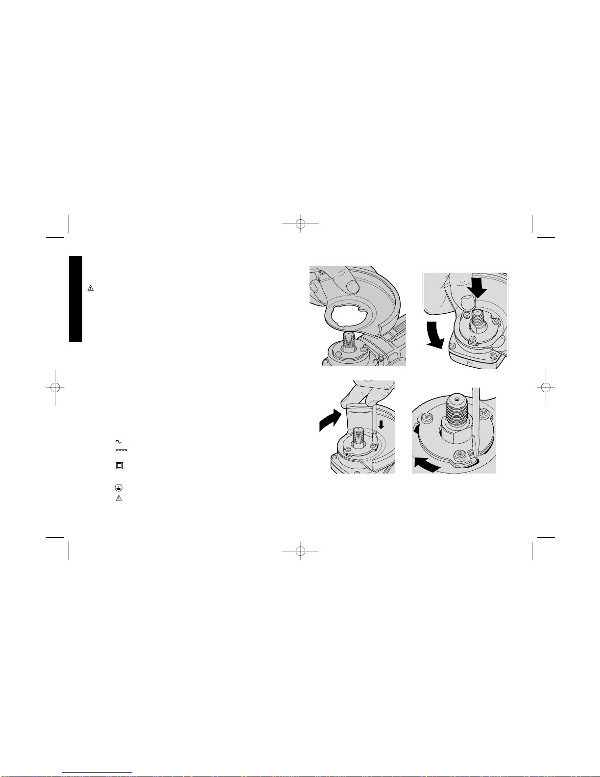
Fitting and Removing the Guard DW830
(Fig. 1 & 1A)
A guard is not required when using the tool for sanding with the
backing pad. To fit the guard for other applications:
1. Align the lug on the guard with the slot in the bracket fixed to the
base of the gear case (Fig. 1).
2. Press the guard down toward the gear case, and then rotate the
guard in the direction of the arrow (Fig. 1A).
3. In this position, the guard locking pin located in the slot prevents the
guard from coming loose, but allows rotation through 105°.
To remove the guard:
1. Place the tool upside down on a flat surface.
2. Hold the tool, and using your thumb, rotate the guard in the
direction of the arrow (Fig. 2). At the same time, using a screwdriver
or other pointed instrument, press the locking pin in the slot so the
lug on the guard comes into view (Fig. 3).
3. The locking pin does not hold the guard, and the guard can be
pushed free.
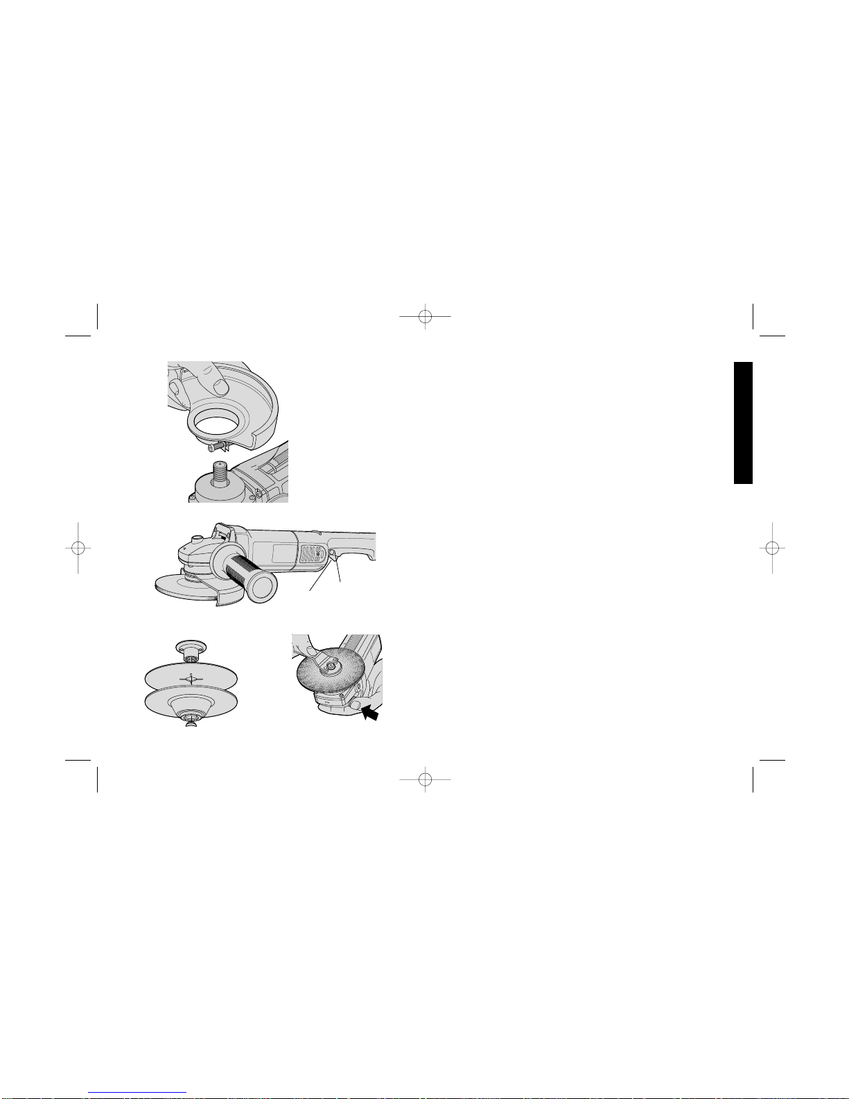
Fitting and Removing the Guard DW840
and DW841 (Fig 4)
1. Place the angle grinder on a table, spindle up.
2. Press the guard down.
4. Position the guard between your body and the work piece.
5. T ighten the cinch collar firmly around the neck of the spindle..
IMPORTANT: Unplug the tool before mounting or removing the guard.
Use the tool without the guard only when sanding with the rubber
backing pad.
Switch (Fig. 5)
To start the tool, squeeze the trigger switch (A) shown in Figure 5. To
turn the tool off, release the switch.The tool can be locked on for
continuous use by holding the trigger switch depressed while you
3
English
FIG. 4
FIG. 5
B
A
FIG. 6
FIG. 7
DW830,etc./569590-01 8/3/00 2:47 PM Page 3
Page 7
4
English
FIG. 8
FIG. 10
FIG. 11
FIG. 9
depress the switch locking button next to the trigger (B). Hold the
locking button in as you gently release the trigger. Release the locking
button and the tool will continue to run. T o turn the tool off from a locked
on condition, squeeze and release the trigger once.
Fitting a Rubber Backing Pad (Fig. 6)
The rubber backing pad is available as an optional accessory. To fit the
pad:
1. Unplug the tool.
2. Remove the guard from the tool.
3. Insert the backing pad onto the machine spindle (Fig. 6). The inner
driven flange in Fig. 9 is not needed.
4. Position the abrasive disc on the pad.
5. Screw the outer flange with the two grip holes, together with the pad
fitted, onto the machine spindle (Fig. 7).
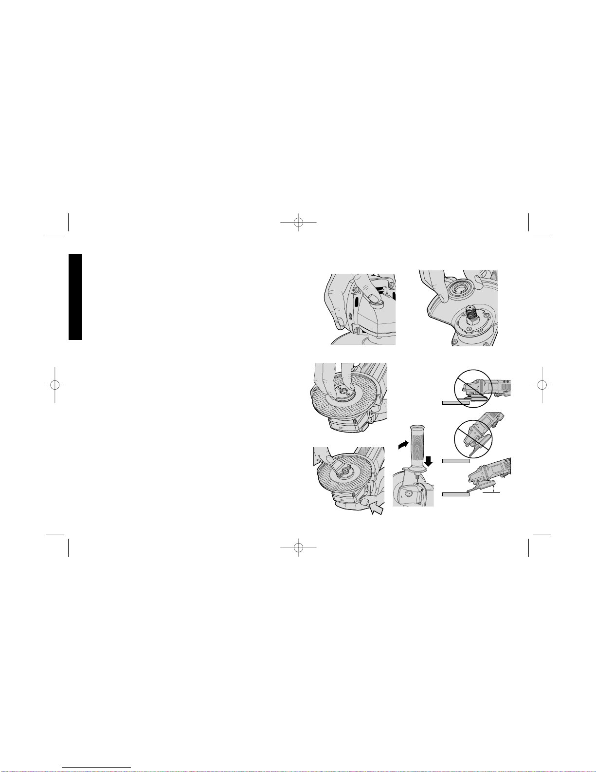
6. With your finger firmly on the spindle lock (Fig. 8), tighten the outer
flange with the pin spanner supplied.
7. Release the spindle lock. You can now plug the tool in and start
work.
8. To remove the backing pad, follow the instructions in reverse order.
IMPORTANT: When using the tool for sanding, allow only a segment
of the disc to contact the work and refrain from high-pressure
application.
Mounting Grinding Wheels
The grinding wheels are available as optional accessories. To fit a
grinding wheel:
1. Disconnect the plug.
2. Locate the inner driven flange on the drive flats on the machine
spindle (Fig. 9).
3. Place the wheel against the flange.
4. Screw the threaded flange onto the spindle (Fig. 10).
5. Rotate the grinding wheel while pressing the spindle lock (on the
front of the gear case) fully until it has found its locking location and
hold the spindle still.
FIG. 12
10° - 15°
FIG. 13
DW830,etc./569590-01 8/3/00 2:47 PM Page 4
Page 8

5
English
6. Firmly tighten the threaded flange with the two-pin spanner
supplied (Fig. 11). You can now plug the tool in and start work.
FOR GRINDING:
Using a depressed center disc, use the tool at an angle of
approximately 30° to the work for roughing. (See figure 13.)
Fitting Wire Cup Brushes
The wire cup brush screws directly on the spindle of the machine
without the use of flanges.
Side-handle (Fig. 12)
The side handle can be fitted to either side of the gear case.
Precautions To Take When Sanding Paint
1. Sanding of lead based paint is NOT RECOMMENDED due to the
difficulty of controlling the contaminated dust. The greatest danger
of lead poisoning is to children and pregnant women.
2. Since it is difficult to identify whether or not a paint contains lead
without a chemical analysis, we recommend the following
precautions when sanding any paint:
PERSONAL SAFETY
a. No children or pregnant women should enter the work area where
the paint sanding is being done until all clean up is completed.
b. A dust mask or respirator should be worn by all persons entering
the work area. The filter should be replaced daily or whenever the
wearer has difficulty breathing.
NOTE: Only those dust masks suitable for working with lead paint
dust and fumes should be used. Ordinary painting masks do not
offer this protection. See your local hardware dealer for the proper
N.I.O.S.H. approved mask.
c. NO EATING, DRINKING or SMOKING should be done in the work
area to prevent ingesting contaminated paint particles. Workers
should wash and clean up BEFORE eating, drinking or smoking.
Articles of food, drink, or smoking should not be left in the work
area where dust would settle on them.
ENVIRONMENTAL SAFETY
a. Paint should be removed in such a manner as to minimize the
amount of dust generated.
b. Areas where paint removal is occurring should be sealed with
plastic sheeting of 4 mils thickness.
c. Sanding should be done in a manner to reduce tracking of paint dust
outside the work area.
CLEANING AND DISPOSAL
a.All surfaces in the work area should be vacuumed and thoroughly
cleaned daily for the duration of the sanding project. Vacuum filter
bags should be changed frequently.
b.Plastic drop cloths should be gathered up and disposed of along
with any dust chips or other removal debris. They should be placed
in sealed refuse receptacles and disposed of through regular trash
pick-up procedures.
During clean up, children and pregnant women should be kept away
from the immediate work area.
c.All toys, washable furniture and utensils used by children should be
washed thoroughly before being used again.
Maintenance
Cleaning
Blowing dust and grit out of the motor housing using compressed air
is a necessary regular maintenance procedure. Dust and grit
containing metal particles often accumulate on interior surfaces and
could create an electrical shock hazard if not frequently cleaned out.
ALWAYS WEAR SAFETY GLASSES.
CAUTION: Never use solvents or other harsh chemicals for
cleaning the non-metallic parts of the tool. Use clean, dry rag only.
Lubrication
DEWALTtools are properly lubricated at the factory and are ready for
use. Tools should be relubricated regularly every sixty days to six
DW830,etc./569590-01 8/3/00 2:47 PM Page 5
Page 9

POUR TOUT RENSEIGNEMENT SUPPLÉMENTAIRE SUR CET
OUTIL OU TOUT AUTRE OUTIL D
E
WALT, COMPOSER SANS
FRAIS LE NUMÉRO SUIVANT.
1 800 4-DEWALT (1 800 433-9258)
Importantes mesures de sécurité
AVERTISSEMENT! Lire et comprendre toutes les directives. Le
non-respect de toutes les directives suivantes présente des risques de
secousses électriques, d'incendie ou de blessures graves.
CONSERVER CES MESURES
Régles de sécurité générales
AVERTISSEMENT! Vous devez lire et comprendre toutes les
instructions. Le non-respect, même partiel, des instructions ci-après
entraîne un risque de choc électrique, d’incendie et/ou de blessures
graves.
ZONE DE TRAVAIL
• S'assurer que la zone de travail est propre et bien éclairée.
Des établis encombrés et des endroits sombres présentent des
risques d'accidents.
• Ne pas utiliser des outils électriques en présence de vapeurs
explosives (comme celles dégagées par des liquides, des gaz
ou des poussières inflammables). Les étincelles générées par
le moteur des outils électriques peuvent enflammer les poussières
ou les vapeurs.
• Éloigner les curieux, les enfants et les visiteurs de la zone de
travail lorsqu'on utilise un outil électrique. Une distraction peut
entraîner la perte de maîtrise de l'outil.
MESURES DE SÉCURITÉ RELATIVES À L'ÉLECTRICITÉ
• Les outils mis à la terre doivent être branchés dans une prise
bien installée et mise à la terre conformément à tous les codes
et règlements en vigueur. Ne jamais retirer la broche de terre ni
modifier la fiche. Ne pas utiliser d'adaptateur pour fiche. Vérifier
auprès d'un électricien certifié en cas de doute quant à la mise à la
6
English
months, depending on usage. (T ools used constantly on production or
heavy-duty jobs and tools exposed to heat may require more frequent
lubrication.) This lubrication should only be attempted by trained power
tool repairpersons, such as those at D
EWALT service centers or in
other qualified service organizations.
Motor Brushes
When brushes become worn, the tool will automatically stop and
prevent damage to the motor. Brush replacement should be performed
by D
EWALTauthorized service centers.
Accessories
Recommended accessories for use with your tool are available at extra
cost from your local dealer or authorized service center. If you need
assistance in locating any accessory for your tool, contact:
DEWALT Industrial Tool Co., 701 East Joppa Road, Baltimore, MD
21286
CAUTION: The use of any other accessory not recommended for
use with this tool could be hazardous.
Full Warranty
DEWALT heavy duty industrial tools are warranted for one year from
date of purchase. We will repair, without charge, any defects due to
faulty materials or workmanship. For warranty repair information, call
1-800-4-D
EWALT. This warranty does not apply to accessories or
damage caused where repairs have been made or attempted by
others. This warranty gives you specific legal rights and you may have
other rights which vary in certain states or provinces.
In addition to the warranty, D
EWALT tools are covered by our:
30 DAY NO RISK SATISFACTION GUARANTEE
If you are not completely satisfied with the performance of your
D
EWALTheavy duty industrial tool, simply return it to the participating
seller within 30 days for a full refund. Please return the complete unit,
transportation prepaid. Proof of purchase may be required.
DW830,etc./569590-01 8/3/00 2:47 PM Page 6
Page 10

7
Français
terre de la prise. En cas de défaillance électrique ou de bris de
l'outil, la mise à la terre procure un chemin de faible résistance au
courant qui autrement traverserait l'utilisateur.
• Les outils à double isolation comportent une fiche polarisée
(une lame plus large que l'autre). La fiche n'entre que d'une
façon dans une prise polarisée. Lorsque la fiche n'entre pas à fond
dans la prise, essayer de nouveau après avoir inversé les broches
de la fiche. Si la fiche n'entre toujours pas dans la prise,
communiquer avec un électricien certifié afin de faire installer une
prise polarisée. Ne modifier en aucune façon la fiche. La double
isolation élimine le besoin d'un cordon trifilaire mis à la terre et d'un
système d'alimentation mis à la terre.
• Éviter de toucher à des surfaces mises à la terre comme des
tuyaux, des radiateurs, des cuisinières et des réfrigérateurs.
Les risques de secousses électriques sont plus élevés si le corps
de l'utilisateur est mis à la terre.
• Protéger les outils électriques de la pluie ou des conditions
mouillées. Une infiltration d'eau dans l'outil augmente les risques
de secousses électriques.
• Manipuler le cordon avec soin. Ne jamais se servir du cordon
afin de transporter l'outil ni tirer sur le cordon pour débrancher l'outil.
Éloigner le cordon des sources de chaleur, des flaques d'huile, des
arêtes tranchantes et des pièces mobiles. Remplacer
immédiatement les cordons endommagés. Les cordons
endommagés augmentent les risques de secousses électriques.
• Lorsqu'on utilise un outil électrique à l'extérieur, se servir d'un
cordon de rallonge prévu pour l'extérieur, portant la mention
«W-A» ou «W». Ces cordons sont conçus pour servir à l'extérieur
et minimisent les risques de secousses électriques.
Calibre minimal des cordons de rallonge
Tension Longueur totale du cordon en pieds
120 V 0-25 26-50 51-100 101-150
240 V 0-50 51-100 101-200 201-300
Intensité (A)
Au Au Calibre moyen de fil (AWG)
moins plus
0-6 18161614
6 - 10 18 16 14 12
10-1216161412
12 - 16 14 12 Non recommandé
SÉCURITÉ DES PERSONNES
• Demeurer vigilant, prendre soin et faire preuve de jugement
lorsqu'on utilise un outil électrique. Ne pas s'en servir lorsqu'on
est fatigué ou affaibli par des drogues, de l'alcool ou des
médicaments. De graves blessures peuvent résulter d'un moment
d'inattention lors de l'utilisation d'un outil électrique.
• Porter des vêtements appropriés. Éviter de porter des
vêtements amples ou des bijoux. Recouvrir la chevelure si elle est
longue. Éloigner les cheveux, les vêtements et les gants des
pièces en mouvement qui peuvent les happer.
• Éviter les démarrages accidentels. S'assurer que l'interrupteur
est en position hors tension avant de brancher l'outil. Afin d'éviter
les risques de blessures, ne pas transporter l'outil avec le doigt sur
l'interrupteur ni brancher un outil dont l'interrupteur est en position
sous tension.
• Enlever les clés de réglage avant de mettre l'outil sous
tension. Une clé qui est laissée sur une pièce rotative de l'outil
présente des risques de blessures.
• Ne pas dépasser sa portée. Garder son équilibre en tout temps.
On s'assure d'une meilleure maîtrise de l'outil dans des situations
imprévues grâce à une position stable et un bon équilibre.
• Porter de l'équipement de sécurité. Toujours porter des lunettes
de sécurité. Dans certaines conditions, il faut porter des masques
respiratoires, des chaussures antidérapantes, un casque de
sécurité ou des protège-tympans.
DW830,etc./569590-01 8/3/00 2:47 PM Page 7
Page 11

Utilisation et entre tien de l'outil
• Utiliser des pinces de serrage ou de tout autre moyen pratique
afin de fixer et de soutenir la pièce à ouvrer sur une plateforme stable. La pièce est instable lorsqu'elle est retenue par la
main ou le corps de l'utilisateur. Cela présente des risques de perte
de maîtrise de l'outil.
• Ne pas forcer l'outil. Utiliser l'outil approprié à la tâche. L'outil
approprié fonctionne mieux et sûrement lorsqu'on s'en sert à son
rendement nominal.
• Ne pas se servir de l'outil lorsque l'interrupteur est défectueux.
Le cas échéant, l'outil est dangereux et il faut le réparer.
• Débrancher l'outil de la source d'alimentation avant de le
régler, d'en remplacer les accessoires ou de le ranger. On
minimise de la sorte le risque de démarrage accidentel de l'outil.
• Ranger l'outil hors de portée des enfants et de toute autre
personne qui n'en connaît pas le fonctionnement. L'outil est
dangereux entre les mains de ces personnes.
• Prendre soin des outils. S'assurer que les outils de coupe sont
tranchants et propres. Des outils bien entretenus à arêtes
tranchantes ont moins tendance à se coincer et ils se maîtrisent
mieux.
• Vérifier l'alignement et les attaches des pièces mobiles, le
degré d'usure des pièces ainsi que tout autre facteur susceptible de
nuire au bon fonctionnement de l'outil. Faire réparer un outil
endommagé avant de s'en servir. Des outils mal entretenus sont
la cause de nombreux accidents.
• Utiliser seulement les accessoires recommandés par le
fabricant. Des accessoires qui conviennent à un outil peuvent
présenter des risques avec un autre outil.
Entretien
• Confier l'entretien de l'outil seulement à du personnel qualifié. Le
non-respect de la présente directive présente des risques de
blessures.
• Lors de l'entretien de l'outil, utiliser seulement des pièces de
rechange identiques. Respecter les consignes relatives à
l'entretien du présent guide d'utilisation. Il y a risque de secousses
électriques ou de blessures lorsqu'on utilise des pièces non
autorisées ou lorsqu'on ne respecte pas les consignes relatives à
l'entretien.
Mesures de sécurité relatives aux
rectifieuses
• Toujours utiliser le protecteur approprié à la meule. Le
protecteur protège l'utilisateur des fragments de meule cassés.
• Utiliser seulement des accessoires dont le régime nominal
équivaut au moins au régime indiqué sur la plaque
signalétique de l’outil. Une meule ou tout accessoire utilisé à une
vitesse excessive peut se détacher de l'outil et provoquer des
blessures.
• Saisir les surfaces isolées de l’outil lorsqu’on s’en sert là où il
pourrait y avoir des fils sous tension et lorsqu’il pourrait entrer
en contact avec son propre fil. En cas de contact avec un fil sous
tension, les composantes métalliques à découvert de l’outil
deviendraient sous tension et l’utilisateur subirait des secousses
électriques.
• Avant de s’en servir, vérifier si les accessoires recommandés
ne renferment aucune fêlure ni défaut. Le cas échéant, jeter
l’accessoire. Il faut également inspecter l’accessoire lorsque l’outil
est tombé.
• Au moment du démarrage (après avoir installé une nouvelle
meule), saisir l’outil dans un endroit bien protégé et le laisser
fonctionner pendant une minute. Si la meule renferme une fêlure
ou un défaut non décelé, elle éclatera en moins de une minute. Ne
jamais mettre l’outil en marche lorsqu’une personne se trouve dans
la trajectoire de la meule. Cette mesure vaut également pour
l’utilisateur.
8
Français
DW830,etc./569590-01 8/3/00 2:47 PM Page 8
Page 12

9
Français
• Pendant les travaux, éviter de faire sauter la meule ou de la
maltraiter. Le cas échéant, arrêter l’outil et inspecter la meule.
• Toujours utiliser la poignée latérale. Il faut toujours se servir de la
poignée latérale afin de bien maîtriser l'outil en tout temps.
• Nettoyer l’outil régulièrement. De la poussière et des saletés
renfermant des particules métalliques s'accumulent souvent sur les
surfaces internes de l'outil et cette accumulation présente un risque
de secousses électriques.
AVERTISSEMENT : Certains outils, tels que les sableuses
électriques, les scies, les meules, les perceuses ou certains autres
outils de construction, peuvent soulever de la poussière contenant des
produits chimiques susceptibles d’entraîner le cancer, des
malformations congénitales ou pouvant être nocifs pour le système
reproductif. Parmi ces produits chimiques, on retrouve :
• le plomb dans les peintures à base de plomb;
• la silice cristalline dans les briques et le ciment et autres produits de
maçonnerie;
• l’arsenic et le chrome dans le bois de sciage ayant subi un
traitement chimique (CCA).
Le risque associé à de telles expositions peut varier selon la fréquence
avec laquelle on effectue ces travaux. Pour réduire l’exposition à de
tels produits, il faut travailler dans un endroit bien ventilé et utiliser
l’équipement de sécurité approprié tel un masque anti-poussières
spécialement conçu pour filtrer les particules microscopiques.
•L’étiquette de l’outil peut comporter les symboles suivants.
V ................................volts
A ................................ampères
Hz ..............................hertz
W ..............................watts
min ............................minutes
............................courant alternatif
..........................courant continu
n
o ..........................sous vide
..............................construction de classe II
/min............................tours ou courses à la minute
..............................borne de mise à la terre
............................symbole d´avertissement
Installation et retrait du protecteur
(Fig. 1)
On peut enlever le protecteur pour effectuer des travaux de ponçage
à l’aide du disque d’appui. Faire ce qui suit pour installer le
protecteur lors de toute autre utilisation.
1. Aligner l’oreille du protecteur dans la fente du support fixé au socle
du boîtier des engrenages (fig. 1).
2. Abaisser le protecteur vers le boîtier des engrenages, puis le faire
pivoter dans le sens de la flèche (fig. 2).
3. Dans cette position, la tige de verrouillage du protecteur située dans
la fente empêche le protecteur de se détacher, mais elle en permet
la rotation jusqu’à 105°.
Faire ce qui suit pour retirer le protecteur.
1. Déposer l’outil à l’envers sur une surface plane.
2. Saisir l’outil et, à l'aide du pouce, faire pivoter le protecteur dans le
sens de la flèche (fig. 3). Simultanément, pousser sur la tige de
verrouillage dans le fente à l’aide d’un tournevis ou d’un autre
instrument pointu jusqu’à ce que l’oreille du protecteur soit visible
(fig. 4).
3. La tige de verrouillage ne retient alors plus le protecteur, qu’on
peut retirer en le poussant.
IMPORTANT : Débrancher l’outil avant d’installer ou de retirer le
protecteur. Utiliser l’outil sans protecteur seulement pour les travaux
de ponçage avec le disque d’appui en caoutchouc.
DW830,etc./569590-01 8/3/00 2:47 PM Page 9
Page 13

10
Français
Interrupteur
Pour actionner l'outil, enfoncer l'interrupteur à détente (fig. 5). Pour
l'arrêter, relâcher l'interrupteur. On peut verrouiller l'outil en mode de
fonctionnement continu en enfonçant l'interrupteur à détente tout en
enfonçant le bouton de verrouillage de l'interrupteur qui se trouve près
de la détente (fig. 5). Maintenir le bouton de verrouillage enfoncé et
relâcher doucement l'interrupteur. On peut alors relâcher le bouton
de verrouillage et l'outil continue de fonctionner. Pour arrêter l'outil
alors qu'il est en mode de fonctionnement continu, enfoncer et relâcher
immédiatement la détente.
Installation d'un disque d'appui en caoutchouc (Fig. 6)
Le disque d’appui en caoutchouc est vendu séparément. Faire ce qui
suit pour l’installer.
1. Débrancher l’outil.
2. Retirer le protecteur de l’outil.
3. Insérer le disque d’appui sur l’arbre (fig. 6). La bride interne (fig. 9)
n’est pas nécessaire.
4. Placer le disque abrasif sur le disque d’appui.
5. Une fois le disque installé, visser la bride externe sur l’arbre en se
servant des deux trous de serrage (fig. 7).
6. En appuyant fermement sur le dispositif de verrouillage de l’arbre
avec un doigt (fig. 8), serrer la bride externe à l’aide de la clé à
griffes fournie.
7. Relâcher le dispositif de verrouillage de l’arbre. L’outil est prêt à être
branché et utilisé.
8. Pour retirer le disque d’appui, répéter les étapes précédentes dans
l’ordre inverse.
IMPORTANT : Lors du ponçage avec l’outil, ne laisser qu’une portion
du disque entrer en contact avec la pièce et éviter d’exercer une trop
grande pression.
Installation de la meule
Les meules sont vendues séparément. Faire ce qui suit pour les
installer.
1. Débrancher l’outil.
2. Placer la bride interne sur les surfaces planes de l’arbre (fig. 9).
3. Placer la meule sur la bride.
4. Visser la bride filetée sur l’arbre (fig. 10).
5. Faire pivoter la meule tout en enfonçant complètement le dispositif
de verrouillage de l’arbre (à l’avant du boîtier des engrenages)
jusqu’à ce que la meule s’enclenche et immobilise l’arbre.
6. Serrer la bride filetée fermement avec la clé à deux griffes incluse
(fig. 11). L’outil est prêt à être branché et utilisé.
Meulage
Lorsqu’on travaille avec un disque à moyeu creux, il faut toujours
donner un angle d’environ 30° à l’outil pour dégrossir (fig. 13).
Installation d'une brosse boisseau
métallique
Visser la brosse boisseau métallique directement sur l’arbre sans avoir
recours aux brides.
Poignée latérale (Fig. 12)
La poignée latérale peut être fixée d’un côté ou de l’autre du boîtier des
engrenages.
Mesures à prendre lors du ponçage de
peinture
1. IL N’EST PAS RECOMMANDÉ de poncer de la peinture à base de
plomb puisqu’il est difficile d’en maîtriser la poussière contaminée.
Ce genre de ponçage présente de sérieux risques
d’empoisonnement au plomb pour les femmes enceintes et les
enfants.
2. Puisqu’il est difficile de déterminer si la peinture renferme du plomb
sans en faire une analyse chimique, il est conseillé de se conformer
DW830,etc./569590-01 8/3/00 2:47 PM Page 10
Page 14

11
Français
aux mesures suivantes lors du ponçage de tout type de peinture.
SÉCURITÉ PERSONNELLE
a. Ne laisser aucun enfant ni aucune femme enceinte entrer dans la
pièce où il y a ponçage de peinture jusqu’à ce que la pièce soit
nettoyée.
b. Toute personne entrant dans la pièce de travail devrait porter un
masque ou un respirateur. L’utilisateur devrait en remplacer le
filtre chaque jour ou dès qu’il éprouve de la difficulté à respirer.
NOTE : Il faut seulement utiliser des masques conçus pour le travail
en présence de poussières ou de vapeurs de plomb. Les masques
ordinaires ne sont pas conçus à cet effet. Consulter le quincaillier pour
choisir le masque approprié.
c. IL EST DÉCONSEILLÉ DE MANGER, DE BOIRE ET DE FUMER
dans la pièce de travail afin de ne pas ingérer de particules
contaminées. L’utilisateur doit se laver et se nettoyer AVANT de
manger, de boire ou de fumer. Il ne faut pas laisser dans la pièce
de travail de la nourriture, des boissons ou des cigarettes car de la
poussière pourrait se déposer sur ces articles.
PROTECTION DE L’ENVIRONNEMENT
a. Il faut enlever la peinture de manière à produire un minimum de
poussière.
b. Il faut sceller la zone de travail à l’aide de feuilles de plastique d’une
épaisseur minimale de 4 mils.
c. Il faut poncer de façon à réduire la propagation de la poussière hors
de la pièce de travail.
NETTOYAGE ET DÉCHETS
a. Il faut bien aspirer toutes les surfaces de la pièce de travail et les
nettoyer à fond chaque jour pendant la durée des travaux. Il faut
remplacer fréquemment le filtre de l’aspirateur.
b. Ramasser les feuilles de plastique et les jeter avec la poussière et
les autres débris dans des contenants étanches à placer avec les
ordures ménagères pour l’enlèvement.
Tenir les enfants et les femmes enceintes à l’écart de la zone de
travail pendant les travaux de nettoyage.
c. Il faut nettoyer à fond les jouets, les meubles et les ustensiles des
enfants avant de les utiliser de nouveau.
Entretien
NETTOYAGE
Le retrait de la poussière du carter du moteur à l’aide d’un jet d’air
comprimé fait partie de l’entretien normal de l’outil. De la poussière
contenant des particules métalliques s’accumule fréquemment sur les
surfaces intérieures et cela présente un risque de secousses
électriques si la poussière n’est pas enlevée régulièrement.
TOUJOURS PORTER DES LUNETTES DE SÉCURITÉ.
MISE EN GARDE : Ne jamais utiliser de solvants ni de produits
chimiques puissants pour nettoyer les composants non métalliques
de l’outil. Utiliser seulement un chiffon sec et propre.
Lubrification
Les outils DeWalt sont lubrifiés et prêts à être utilisés à leur sortie de
l’usine. Ils devraient être lubrifiés régulièrement, entre 60 jours et six
mois, selon l’usage qu’on en fait. (Les outils constamment utilisés ou
servant aux travaux de service intensif ainsi que ceux exposés à la
chaleur peuvent nécessiter des lubrifications plus fréquentes.) Confier
la lubrification à des techniciens qualifiés, comme ceux des centres
de service DeWalt et des autres centres de service autorisés.
Balais du moteur
Lorsque les balais sont usés, l’outil s’arrête automatiquement afin de
ne pas endommager le moteur. Confier le remplacement des balais du
moteur au personnel des centres de service autorisés DeWalt.
Accessoires
On peut se procurer en sus les accessoires recommandés pour l’outil
chez les détaillants ou aux centres de service autorisés. Pour trouver
un accessoire pour l’outil, communiquer à l’adresse suivante.
DW830,etc./569590-01 8/3/00 2:47 PM Page 11
Page 15

12
Français
DEWALT Industrial Tool Co., 701 East Joppa Road, Baltimore, MD
21286 É.-U.
MISE EN GARDE : L’utilisation de tout autre accessoire non
recommandé pour l’outil peut être dangereuse.
Garantie complète
Les outils industriels de service intensif DEWALT sont garantis
pendant un an à partir de la date d’achat. Toute pièce d’un outil
D
EWALT qui s’avérait défectueuse en raison d’un vice de matière ou
de fabrication sera réparée ou remplacée sans frais. Pour obtenir de
plus amples renseignements sur les réparations couvertes par la
garantie, composer le 1 (800) 4-D
EWALT (! (800) 433-9258). La ga
rantie ne couvre pas les accessories ni les réparations tentées ou
effectuées par des tiers. Les modalités de la présente garantie
donnent des droits légaux spécifiques. L’utilisateur peut également
se prévaloir d’autres droits selon l’état ou la province qu’il habite.
En outre, la garantie suivante couvre les outils D
EWALT.
GARANTIE DE SATISFACTION DE 30 JOURS OU ARGENT REMIS
Si, pour quelque raison que ce soit, l’outil industriel de service intensif
D
EWALT ne donne pas entière satisfaction, il suffit de le retourner
chez le marchand participant dans les 30 jours suivant la date
d’achat afin d’obtenir un remboursement complet. Il faut retourner,
port payé, l’outil complet. On peut exiger une preuve d’achat.
Imported by / Importé par
D
EWalt Canada Inc.
100 Central Ave.
Brockville (Ontario) K6V 5W6
Voir la rubrique “Outils électriques”
des Pages Jaunes
pour le service et les ventes.
Instrucciones importantes de seguridad
ADVERTENCIA: Lea y comprenda todas las instrucciones. No
seguir todas las instrucciones enlistadas a continuación puede
resultar en choque eléctrico, incendio y (o) lesiones personales de
gravedad.
CONSERVE ESTAS
INSTRUCCIONES
AREA DE TRABAJO
• Conser ve su área de trabajo limpia y bien iluminada. Los
bancos con objetos acumulados en desorden y las zonas oscuras
propician los accidentes.
• No opere herramientas eléctricas en atmósferas explosivas,
como en presencia de líquidos gases o polvos inflamables. Las
herramientas eléctricas producen chispas que pueden originar la
ignición de estos polvos o vapores.
• Conserve a observadores, niños y visitantes alejados mientras
opera una herramienta eléctrica. Las distracciones pueden
ocasionar que pierda el control.
SEGURIDAD ELECTRICA
• Las herramientas con tierra deben conectarse a una toma de
corriente instalada y aterrizada correctamente de conformidad con todos los códigos y regulaciones locales. Nunca
elimine la pata de conexión a tierra ni modifique la clavija en
ninguna manera. No utilice clavijas adaptadoras. Consulte con un
electricista calificado si tiene dudas acerca de la conexión correcta
a tierra de su toma de corriente. En el caso que su herramienta
tenga una falla eléctrica, el aterrizaje proporciona una vía de baja
resistencia para llevar la electricidad lejos del operador.
• Las herramientas con doble aislamiento están equipadas con una
clavija polarizada (con una pata más ancha que la otra). Esta clavija
se acoplará únicamente a una toma de corriente polarizada en
una manera. Si la clavija no se acopla al contacto, inviértala. Si
DW830,etc./569590-01 8/3/00 2:47 PM Page 12
Page 16

13
Français
aún así no se ajusta, comuníquese con un electricista calificado
para que le instalen una toma de corriente polarizada apropiada.
El doble aislamiento elimina la necesidad de cables con tres
hilos y sistemas de alimentación con conexión a tierra.
• Evite el contacto corporal con superficies aterrizadas tales
como tuberías, radiadores, hornos y refrigeradores. Hay un
gran riesgo de choque eléctrico si su cuerpo hace tierra.
• No exponga las herramientas eléctricas a la lluvia o a
condiciones de mucha humedad. El agua que se introduce a las
herramientas aumenta el riesgo de descargas eléctricas.
• No maltrate el cable. Nunca tome el cable para transportar una
herramienta ni para desconectarla de la toma de corriente.
Consérvelo alejado de calor, aceite, bordes afilados o piezas
móviles. Cambie inmediatamente los cables dañados. Los cables
dañados aumentan el riesgo de choque eléctrico.
• Cuando opere una herramienta eléctrica a la intemperie,
utilice una extensión marcada “W-A” o “W”. Estas extensiones
está clasificadas para usarse a la intemperie y para reducir el riesgo
de choques eléctricos.
Calibre mínimo para cordones de extensión
Volts Longitud total del cordón en metros
120V 0-7,6 7,6-15,2 15,2-30,4 30,4-45,7
240V 0-15,2 15,2-30,4 30,4-60,9 60,9-91,4
AMPERAJE
Más No más Calibre del cordón AWG
de de
0-6 18161614
6 - 10 18 16 14 12
10-1216161412
12 - 16- 14 12 No recomendado
SEGURIDAD PERSONAL
• Esté alerta, concéntrese en lo que está haciendo. recurra al
sentido común cuando opere una herramienta eléctrica. No
opere ninguna herramienta si se encuentra fatigado o bajo la
influencia de drogas, alcohol o medicamentos. Un momento de
desatención mientras se operan herramientas eléctricas puede
ocasionar lesiones graves.
• Vístase de manera adecuada. No tenga puestas ropas o artículos
de joyería flojos. Cubra su cabello si lo tiene largo. Conserve su
cabello, sus ropas y guantes alejados de las piezas móviles. Las
piezas de vestir flojas, las joyas y el cabello largo pueden quedar
atrapados por las piezas móviles.
• Evite el encendido accidental. Asegúrese que el interruptor esté
en posición de apagado antes de conectar. Sostener una
herramienta con el dedo en el interruptor, o conectarla sin fijarse si
el interruptor está en posición de encendido propicia los accidentes.
• Retire las llaves de ajuste antes de encender la herramienta.
Una llave que se deja en una pieza giratoria puede ocasionar
lesiones personales.
• No se sobreextienda. Conserve siempre los pies bien apoyados,
al igual que el equilibrio. La posición correcta de los pies y el
equilibrio permiten controlar mejor la herramienta en situaciones
inesperadas.
• Utilice equipo de seguridad. Siempre utilice protección en los
ojos. Se deben utilizar mascarillas contra polvo, zapatos
antiderrapantes, casco o protectores para los oídos para tener las
condiciones de trabajo adecuadas.
USO Y CUIDADOS DE LA HERRAMIENTA
• Utilice prensas u otros medios prácticos para asegurar y
apoyar la pieza de trabajo en una plataforma estable. Sujetar
las piezas con la mano o contra su cuerpo es inestable y puede
originar la pérdida de control.
• No fuerce la herramienta. Utilice la herramienta adecuada para
su aplicación. La herramienta correcta hará el trabajo mejor y de
manera más segura bajo las especificaciones para las que se
diseñó.
• No utilice la herramienta si el interruptor no enciende y apaga.
Cualquier herramienta que no pueda controlarse por medio del
interruptor es peligrosa y éste debe reemplazarse.
DW830,etc./569590-01 8/3/00 2:47 PM Page 13
Page 17

14
Español
• Desconecte la clavija de la toma de corriente antes de hacer
cualquier ajuste, cambio de accesorios o de guardar la
herramienta. Tales medidas de seguridad reducen el riesgo de
encender la herramienta por accidente.
• Guarde las herramientas que no emplee fuera del alcance de
niños y otras personas sin entrenamiento. Las herramientas son
peligrosas en manos de personas sin entrenamiento.
• Cuide sus herramientas. Conserve las herramientas de corte
afiladas y limpias. Las herramientas con mantenimiento adecuado
y con bordes cortantes afilados, son menos propensas a atorarse
y provocar la pérdida de control.
• Revise en busca de mala alineación o piezas móviles atoradas,
ruptura de piezas y cualesquiera otras condiciones que
pudiesen afectar la operación de la herramienta. Si su
herramienta está dañada, haga que le efectúen servicio antes de
utilizarla. Muchos accidentes son ocasionados por herramientas
con mantenimiento pobre.
• Utilice únicamente los accesorios recomendados por el
fabricante para su modelo. Los accesorios que sirven para una
herramienta, pueden volverse peligrosos cuando se emplean con
otra.
SERVICIO
• El ser vicio a las herramientas deberá ser efectuado únicamente por personal calificado. El servicio o mantenimiento
realizado por personal no calificado puede resultar en un riesgo de
lesión.
• Cuando haga servicio a una herramienta, utilice únicamente
refacciones idénticas. Siga las instrucciones de la sección de
mantenimiento de este manual. El empleo de partes no
autorizadas, o no seguir las instrucciones de mantenimiento puede
crear riesgos de choque eléctrico o lesiones.
Doble aislamiento
Las herramientas doblemente aisladas se han elaborado de manera
integral con dos “capas” separadas, o una de DOBLE espesor, de
aislamiento eléctrico entre usted y el sistema eléctrico que contienen.
Las herramientas elaboradas con este sistema de aislamiento no
requieren conectarse a tierra. Como resultado, su unidad está
equipada con una clavija de dos patas que le permite emplear
cordones de extensión sin preocuparse por tener una conexión a
tierra.
NOTA: el doble aislamiento no substituye a las precauciones normales
de seguridad cuando se opera esta herramienta. La finalidad de este
sistema de aislamiento es ofrecer a usted protección añadida contra la
lesión resultante de fallas en el aislamiento eléctrico interno de la
unidad.
PRECAUCION: UTILICE SOLAMENTE REFACCIONES
IDENTICAS cuando se haga servicio a cualquier herramienta. Repare
o reemplace los cordones eléctricos dañados.
Clavija polarizada
Se emplean clavijas polarizadas (con una pata más ancha que la otra)
para reducir los riesgos de choque eléctrico. Cuando el cordón
eléctrico cuente con este tipo de clavija, ajustará en un contacto
polarizado solamente de una manera. Si la clavija no ajusta
completamente en su contacto, inviértala. Si aún así no ajusta, llame
a un electricista calificado para que le instale un contacto polarizado
apropiado. No modifique o haga cambios en la clavija por ningún
motivo.
•
Instrucciones adicionales de seguridad
para esmeriladoras
• Utilice siempre la guarda adecuada para su piedra de esmeril.
La guarda protege al operador de los fragmentos de la piedra que
se desprenden.
• Los accesorios deben estar clasificados para al menos la
velocidad recomendada en la etiqueta de advertencia de la
herramienta. Los discos y otros accesorios que funcionen por
arriba de su velocidad de operación nominal pueden estallar, con el
consiguiente riesgo de lesiones.
• Sujete la herramienta por las superficies aislantes cuando
DW830,etc./569590-01 8/3/00 2:47 PM Page 14
Page 18

15
Español
realice operaciones en las que la herramienta de corte pueda
tocar cableados ocultos o su propio cable. Hacer contacto con
un cable “vivo” hará que las partes metálicas de la herramienta
que quedan expuestas se vuelvan “vivas” dando una descarga al
operador.
• Antes de emplear un accesorio recomendado, revíselo en
busca de fallas o cuarteaduras. Si tal falla es evidente, deseche
el accesorio. Debe revisar el accesorio siempre que usted piense
que la herramienta se ha caído.
• Cuando encienda la herramienta (con un disco nuevo o uno de
repuesto instalado) sujete la herramienta en una zona bien
protegida y déjela funcionar durante un minuto. Si la piedra tiene
una cuarteadura que no se haya detectado, deberá estallar en
menos de un minuto. Nunca encienda la herramienta cuando haya
una persona alineada con el disco; esto incluye al propio operador.
• Evite que la rueda opere a saltos o se maltrate mientras está
en funcionamiento. Si sucediera así, apague y desconecte la
herramienta y revise la piedra.
• UTILICE SIEMPRE EL MANGO LATERAL.Debe utilizar el mango
lateral para conservar el control de la herramienta siempre.
• Limpie su herramienta periódicamente. El polvo de esmeril
contiene a menudo partículas metálicas que se acumulan en el
interior y pueden originar un riesgo de choque eléctrico.
PRECAUCION: Algunos tipos de madera contienen conservadores
como el arsenato cúprico de cromo (CCA) que pueden ser tóxicos.
Cuando lije estos materiales, debe tener precaución para evitar la
inhalación y minimizar el contacto de estas sustancias con la piel.
• La etiqueta de su herramienta puede incluir los siguientes
símbolos.
V .............. volts
A .............. amperes
Hz.............. hertz
W .............. watts
.../min ........ minutos
.............. corriente alterna
.......... corriente directa
n
o.............. velocidad sin carga
.............. construcción Clase II
/min .......... revoluciones o reciprocaciones por minuto
.............. erminales de conexión a tierre
..............símbolo de alerta de seguridad
Carbones del motor
DEWALT utiliza un avanzado sistema de carbones que detiene
automáticamente el motor del taladro cuando se desgastan estas
piezas. Esto impide que el motor se dañe seriamente.
CONSERVE EST AS INSTRUCCIONES
Instalación y remoción de la guarda
(fig. 1)
No se requiere usar una guarda cuando emplee la herramienta para
lijar con la base de respaldo. Para colocar la guarda para otras
aplicaciones:
1. Haga coincidir la protuberancia de la guarda con la ranura en el
soporte fijado a la base de la caja de engranes (fig. 1).
2. Oprima la guarda contra la caja de engranes, y a continuación gírela
en dirección de la flecha (fig. 2).
3. En esta posición, el perno de seguridad de la guarda que se localiza
en la ranura evita que la guarda se afloje, pero permite girarla hasta
105°.
Para quitar la guarda:
1. Coloque la herramienta de cabeza sobre una superficie plana.
2. Sujete la herramienta, gire la guarda con la ayuda de su pulgar en
dirección de la flecha (fig. 3). Al mismo tiempo, con un destornillador
u otro instrumento puntiagudo, oprima el perno de seguridad que se
encuentra en la ranura para que la protuberancia de la guarda
quede a la vista (fig. 4).
DW830,etc./569590-01 8/3/00 2:47 PM Page 15
Page 19

16
Español
3. El perno de seguridad no sujeta la guarda, y puede empujarse
libremente.
IMPORTANTE: Desconecte la herramienta antes de montar o
desmontar la guarda. Use la herramienta sin la guarda solamente
cuando lije con el respaldo de goma instalado.
Interruptor
Para encender la herramienta, oprima el interruptor de gatillo que se
muestra en la figura 5. Para apagar la herramienta, libere el gatillo. La
herramienta puede asegurarse en modo de encendido permanente
para operación continua sujetando el interruptor al mismo tiempo que
oprime el botón del seguro del interruptor que se encuentra junto al
gatillo. Sujete el botón del seguro y libere suavemente el interruptor de
gatillo. Suelte el botón del seguro y la herramienta continuará en
funcionamiento. Para apagar la herramienta desde la posición de
encendido permanente, oprima y libere el gatillo una vez.
Encendido de la herramienta (fig. 5)
Para encender la esmeriladora, deslice hacia atrás y oprima el
interruptor de ENCENDIDO y APAGADO. Para sujetar la unidad de
manera más cómoda a dos manos, presione el interruptor de
ENCENDIDO y APAGADO y oprima la palanca del interruptor. Sujete
la palanca del interruptor mientras suelta el interruptor de ENCENDIDO
y APAGADO. La herramienta continuará en funcionamiento mientras
cualquier parte de la palanca del interruptor de conserve oprimida.
Operación continua
Para operar la herramienta en modo de encendido permanente, sujete
el interruptor de encendido y apagado y oprima y DESLICE HACIA
ADELANTE el botón de seguro del interruptor. Libere el botón del
seguro y el interruptor y la herramienta continuará en funcionamiento.
Para apagara la herramienta desde el modo de operación continua,
oprima y suelte el interruptor de encendido y apagado una vez.
Instalación del disco de respaldo de
goma (fig. 6)
Los discos de esmeril son accesorios opcionales. Para instalar un
disco de esmeril.
1 .Desconecte la clavija.
2. Coloque la arandela interior sobre los planos del cuadro de mando
en la flecha de la máquina (figura 9).
3. Coloque el disco contra la arandela.
4. Enrosque la arandela con cuerda en la flecha (fig. 10).
5. Gire el disco mientras oprime completamente el seguro de la flecha
(al frente de la caja de engranes) hasta que llegue a posición
segura y conserve fija la flecha.
6. Apriete con firmeza la arandela con cuerda con la llave de pernos
que se suministra (fig. 11). Ahora puede conectar la herramienta y
comenzar a trabajar.
Instalación de discos de esmeril
y de corte
Los discos de esmeril y de corte son accesorios opcionales. Para
instalar un disco de esmeril o de corte:
1. Desconecte la clavija.
2. Coloque la arandela interior sobre los planos del cuadro de mando
en la flecha de la máquina (fig. 9).
3. Coloque la piedra o el disco contra la arandela.
4. Enrosque la arandela con cuerda en la flecha (fig. 10).
5. Gire el disco o la piedra mientras oprime el seguro de la flecha (al
frente de la caja de engranes) completamente hasta que llegue a
posición segura y conserve fija la flecha.
6. Apriete con firmeza la arandela con cuerda con la llave de pernos
que se suministra (fig. 11). Ahora puede conectar la herramienta y
comenzar a trabajar.
DW830,etc./569590-01 8/3/00 2:47 PM Page 16
Page 20

17
Español
PARA ESMERILAR:
Cuando utilice piedras con centro realzado, sujete la herramienta de
manera que haya un ángulo aproximado a 30° en relación con la
superficie que vaya a desbastar (figura 13).
PARA CORTAR:
Con disco plano de corte, siempre aproxímese a la pieza e trabajo en
el ángulo en el que desee hacer el corte. Conserve este ángulo
durante todo el corte y no aplique presión lateral al disco.
Instalación de cepillos cónicos de
alambre
Los cepillos cónicos de alambre se enroscan directamente en la flecha
de la máquina sin usar las arandelas.
Mango lateral (fig. 12)
El mango lateral puede colocarse a cualquier lado de la caja de
engranes.
Precauciones cuando lije pintura
1. NO SE RECOMIENDA el lijado de pintura con base de plomo, por
la dificultad para controlar el polvo contaminado. Los niños y las
mujeres embarazadas son las personas con mayor peligro de sufrir
envenenamiento por plomo.
2. Ya que es difícil identificar si una pintura contiene plomo sin un
análisis químico, recomendamos seguir las precauciones que
siguen cuando se lije cualquier tipo de pintura.
SEGURIDAD PERSONAL
a. No deben tener acceso al área de trabajo niños ni mujeres
embarazadas hasta que ésta se encuentre perfectamente limpia.
b. Todas las personas que ingresen en el área de trabajo deberán
utilizar máscara contra polvo o un respirador. El filtro deberá
reemplazarse diariamente o en el momento en que el usuario
perciba dificultad para respirar a través del dispositivo.
NOTA: Sólo deben emplearse máscaras contra polvo adecuadas
para vapores y polvos originados en pintura que contiene plomo.
Las máscaras ordinarias para pintar no ofrecen ésta protección.
Consulte a su distribuidor local de ferretería para que le recomiende
el equipo adecuado.
c. NO se deberá COMER, BEBER NI FUMAR en el área de trabajo,
para evitar la ingestión de partículas de pintura contaminadas. El
operador deberá lavarse y limpiarse ANTES de comer, beber o
fumar. No se deben dejar artículos de estas clases en un área de
trabajo en la que se puede asentar polvo.
SEGURIDAD AMBIENTAL
a. La pintura debe removerse de manera que se minimice la cantidad
generada de polvo.
b. Se deben sellar los accesos a las áreas en donde se está
removiendo pintura con hojas de plástico cuyo espesor mínimo sea
de 0.1 mm.
c. El lijado se debe realizar de manera que se reduzca la salida de
polvo de pintura fuera del área de trabajo.
LIMPIEZA Y DESECHO
a. Todas las superficies en el área de trabajo deben aspirarse y
limpiarse diariamente mientras dure el lijado. Se deben cambiar
con frecuencia los filtros de bolsa de la aspiradora.
b. Las telas plásticas de recolección se deben recoger y desechar con
todos los restos de polvo y de pintura. Se colocarán en recipientes
desechables sellados, y se desecharán por medio del servicio de
recolección regular de basura. Debe procurarse que, durante la
limpieza, no haya niños ni mujeres embarazadas en las
proximidades del área de trabajo.
c. Todos los juguetes, mobiliario y utensilios usados por niños deben
lavarse a conciencia antes de que se vuelvan a utilizar.
Limpieza
Un procedimiento indispensable de mantenimiento de su unidad es la
eliminación, con regularidad, del polvo y las rebabas que se acumulan
DW830,etc./569590-01 8/3/00 2:47 PM Page 17
Page 21

18
Español
en la coraza de la herramienta mediante sopleteado con aire
comprimido. A menudo se acumulan en la superficie interior de ésta
polvo y partículas metálicas que crean el peligro de choque eléctrico,
por lo que es necesaria su eliminación con frecuencia. SIEMPRE
UTILICE GAFAS DE SEGURIDAD.
PRECAUCION: Nunca utilice solventes o productos químicos
agresivos para limpiar las partes no metálicas de la herramienta.
Utilice exclusivamente trapo limpio y seco.
Mantenimiento
Lubricación
La herramientas DeWalt vienen lubricadas de origen y están listas
para emplearse. Deben relubricarse con regularidad cada 60 días a
seis meses, según la frecuencia con que se utilicen. (Pueden requerir
lubricación más frecuente las unidades que se emplean
constantemente en trabajos pesados, lo mismo que las expuestas al
calor). Debe efectuar esta lubricación personal especializado, como
el de los Centros de Servicio Black & Decker o de otras organizaciones
de servicio autorizadas.
Carbones del motor
DEWALT utiliza un avanzado sistema de escobillas que detiene
automáticamente el motor de la esmeriladora cuando se desgastan
estas piezas. Esto impide que el motor se dañe seriamente. El cambio
de carbones debe ser realizado únicamente por los centros de servicio
autorizado D
EWALT.
Accesorios
Dispone usted de los accesorios recomendados para su herramienta
con cargo adicional con su distribuidor local o en los centros de
servicio autorizado. Si necesita usted ayuda para encontrar algún
accesorio, haga por favor contacto con:
D
EWALT Industrial Tool Co., 701 East Joppa Road, Baltimore, MD
21286
Importante
Para garantizar la SEGURIDAD y la CONFIABILIDAD, deberán
hacerse reparaciones, mantenimiento y ajustes de esta herramienta
en los centros de servicio para herramientas industriales de D
EWALT.
u otras organizaciones calificadas. Estas organizaciones prestan
servicio a las herramientas D
EWALT y emplean siempre refacciones
legítimas D
EWALT.
PRECAUCION: El uso de cualquier accesorio no recomendado
para emplearse con esta herramienta puede ser peligroso.
PARA REPARACION Y SERVICIO DE SUS HERRAMIENTAS
ELECTRICAS FAVOR DE DIRIGIRSE AL CENTRO DE SERVICIO MAS
CERCANO
CULIACAN
Av. Nicolas Bravo #1063 Sur (91 671) 242 10
GAUDALAJARA
Av. La Paz #1779 (91 3) 826 69 78.
MEXICO
Eje Lázaro Cárdenas No. 18 Local D, Col. Obrera 588-9377
MERIDA
Calle 63 #459-A (91 99) 23 54 90
MONTERREY
Av. Francisco I. Madero Pte. 1820-A (91 83) 72 11 25
PUEBLA
17 Norte #205 (91 22) 46 37 14
QUERETARO
Av. Madero 139 Pte. (91 42) 14 16 60
SAN LOUIS POTOSI
Pedro Moreno #100 Centro (91 48) 14 25 67
TORREON
Blvd. Independencia, 96 pte. (91 17) 16 52 65
VERACRUZ
DW830,etc./569590-01 8/3/00 2:47 PM Page 18
Page 22

19
Español
Epecificaciones (DW830 (DW840,DW841)
Tensión de alimentación 120 V CA 120 V CA
Potencia nominal: 225 W 225 W
Frecuencia de operación: 60 Hz 60 Hz
Consumo de corriente: 6,5 A 6,5 A
Prolongación Diaz Miron #4280 (91 29) 21 70 16
VILLAHERMOSA
Constitucion 516-A (91 93) 12 53 17
PARA OTRAS LOCALIDADES LLAME AL: 326 7100
Garantía Completa
Las herramientas industriales DEWALT están garantizadas durante un año a
partir de la fecha de compra. Repararemos, sin cargos, cualquier falla debida
a material o mano de obra defectuosos. Por favor regrese la unidad completa,
con el transporte pagado, a cualquier Centro de Servicio para Herramientas
Industriales de DEWALT o a las estaciones de servicio autorizado enlistadas
bajo "Herramientas Eléctricas" en la Sección Amarilla. Esta garantía no se
aplica a los accesorios ni a daños causados por reparaciones efectuadas
por terceras personas. Esta garantía le otorga derechos legales específicos,
y usted puede tener otros derechos que pueden variar de estado a estado.
En adición a la garantía, las herramientas DE
WALT están amparadas por
nuestra:
GARANTÍA DE SATISFACCIÓN SIN RIESGO POR 30 DÍAS
Si usted no se encuentra completamente satisfecho con el desempeño de
su herramienta industrial D
EWALT, sencillamente devuélvala a los
vendedores participantes durante los primeros 30 días después de la fecha
de compra para que le efectúen un reembolso completo. Por favor regrese
la unidad completa, con el transporte pagado. Se puede requerir prueba de
compra.
IMPORTADO: DEWALT S.A. DE C.V.
BOSQUES DE CIDROS ACCESO RADIATAS NO. 42
COL. BOSQUES DE LAS LOMAS.
05120 MÉXICO, D.F
TEL. 326-7100
SECCI N
AMARILLA
Si funciona…
y funciona muy bien.
Para servicio y ventas consulte
“HERRAMIENTAS ELECTRICAS”
en la sección amarilla.
DW830,etc./569590-01 8/3/00 2:47 PM Page 19
 Loading...