

Page 1

DEWA LT Industrial Tool Co., 701 East Joppa Road, Baltimore, MD 21286 (FEB04 CD1)
Form No. 622422-00 DW828 Copyright © 2004
The following are trademarks for one or more DEWA LT power tools: the yellow and black color scheme;
the “D” shaped air intake grill; the array of pyramids on the handgrip; the kit box configuration; and the
array of lozenge-shaped humps on the surface of the tool.
IF YOU HAVE A N Y QUESTIONS OR COMMENTS A B O U T THIS OR A N Y DEWA LT TO O L ,
C A L L US TO L L FREE AT: 1 - 8 0 0 - 4 - DEWA LT (1-800-433-9258)
General Safety Rules
WARNING! Read and understand all instructions. Failure to follow all
instructions listed below may result in electric shock, fire and/or serious
personal injury.
SAVE THESE INSTRUCTIONS
WORK A R E A
• Keep your work area clean and well lit. Cluttered benches and dark areas invite accidents.
• Do not operate power tools in explosive atmospheres, such as in the presence of
flammable liquids, gases, or dust. Power tools create sparks which may ignite the dust or
f u m e s .
• Keep bystanders, children, and visitors away while operating a power tool. D i s t r a c t i o n s
can cause you to lose control.
E L E C T R I C A L S A F E T Y
• Grounded tools must be plugged into an outlet properly installed and grounded in
accordance with all codes and ordinances. Never remove the grounding prong or
modify the plug in any way. Do not use any adapter plugs. Check with a qualified
electrician if you are in doubt as to whether the outlet is properly grounded. If the tools
should electrically malfunction or break down, grounding provides a low resistance path to
carry electricity away from the user. Applicable only to Class I (grounded) tools.
• Double insulated tools are equipped with a polarized plug (one blade is wider than the
o t h e r .) This plug will fit in a polarized outlet only one way. If the plug does not fit fully in
the outlet, reverse the plug. If it still does not fit, contact a qualified electrician to install
a polarized outlet. Do not change the plug in any way. Double insulation eliminates the
need for the three wire grounded power cord and grounded power supply system. A p p l i c a b l e
only to Class II (double insulated) tools.
• Avoid body contact with grounded surfaces such as pipes, radiators, ranges and
r e f r i g e r a t o r s . There is an increased risk of electric shock if your body is grounded.
• D o n ’ t expose power tools to rain or wet conditions. Water entering a power tool will
increase the risk of electric shock.
• Do not abuse the cord. Never use the cord to carry the tools or pull the plug from an
outlet. Keep cord away from heat, oil, sharp edges or moving parts. Replace damaged
cords immediately. Damaged cords increase the risk of electric shock.
• When operating a power tool outside, use an outdoor extension cord marked “W-A” or
“ W.” These cords are rated for outdoor use and reduce the risk of electric shock. When using
an extension cord, be sure to use one heavy enough to carry the current your product will
d r a w . An undersized cord will cause a drop in line voltage resulting in loss of power and
overheating. The following table shows the correct size to use depending on cord length and
nameplate ampere rating. If in doubt, use the next heavier gage. The smaller the gage
n u m b e r, the heavier the cord.
Recommended Minimum Wire Size for Extension Cords
Total Length of Cord
25 ft. 50 ft. 75 ft. 100 ft. 125 ft. 150 ft. 175 ft.
7.6 m 15.2 m 22.9 m 30.5 m 38.1 m 45.7 m 53.3 m
Wire Size AW G
1 8 1 8 1 6 1 6 1 4 14 1 2
P E R S O N A L S A F E T Y
• Stay alert, watch what you are doing and use common sense when operating a power
tool. Do not use tool while tired or under the influence of drugs, alcohol, or medication.
A moment of inattention while operating power tools may result in serious personal injury,
• Dress properly. Do not wear loose clothing or jewelry. Contain long hair. Keep your
h a i r, clothing, and gloves away from moving parts. Loose clothing, jewelry, or long hair
can be caught in moving parts. Air vents often cover moving parts and should also be avoided.
• Avoid accidental starting. Be sure switch is off before plugging in. Carrying tools with
your finger on the switch or plugging in tools that have the switch on invites accidents.
• Remove adjusting keys or wrenches before turning the tool on. A wrench or key that is
left attached to a rotating part of the tool may result in personal injury.
• Do not overreach. Keep proper footing and balance at all times. Proper footing and
balance enables better control of the tool in unexpected situations.
• Use safety equipment. Always wear eye protection. Dust mask, non-skid safety shoes,
hard hat, or hearing protection must be used for appropriate conditions.
TO O L USE AND CARE
• Use clamps or other practical way to secure and support the workpiece to a stable
platform. Holding the work by hand or against your body is unstable and may lead to loss of
c o n t r o l .
• Do not force tool. Use the correct tool for your application.The correct tool will do the job
better and safer at the rate for which it is designed.
• Do not use tool if switch does not turn it on or off . Any tool that cannot be controlled with
the switch is dangerous and must be repaired.
• Disconnect the plug from the power source before making any adjustments, changing
accessories, or storing the tool. Such preventative safety measures reduce the risk of
starting the tool accidentally.
• Store idle tools out of reach of children and other untrained persons. Tools are
dangerous in the hands of untrained users.
• Maintain tools with care. Keep cutting tools sharp and clean. Properly maintained tools,
with sharp cutting edges are less likely to bind and are easier to control.
• Check for misalignment or binding of moving parts, breakage of parts, and any other
condition that may affect the tools operation. If damaged, have the tool serviced before
u s i n g . Many accidents are caused by poorly maintained tools.
• Use only accessories that are recommended by the manufacturer for your model.
Accessories that may be suitable for one tool, may become hazardous when used on another
t o o l .
S E R V I C E
• Tool service must be performed only by qualified repair personnel. Service or
maintenance performed by unqualified personnel could result in a risk of injury.
• When servicing a tool, use only identical replacement parts. Follow instructions in the
Maintenance section of this manual. Use of unauthorized parts or failure to follow
Maintenance Instructions may create a risk of electric shock or injury.
Additional Specific Safety Instructions for Cut-Off To o l s
• Always use proper guard with grinding wheel. A guard protects operator from broken
wheel fragments and wheel contact.
• Accessories must be rated for at least the speed recommended on the tool warning
l a b e l . Wheels and other accessories running over rated speed can fly apart and cause
i n j u r y. Accessory ratings must be above listed minimum wheel speed as shown on tool
n a m e p l a t e .
• Hold tool by insulated gripping surfaces when performing an operation where the
cutting tool may contact hidden wiring or its own cord. Contact with a “live” wire will
make exposed metal parts of the tool “live” and shock the operator.
• Do not use Type 11 (flaring cup) wheels on this tool. Using inappropriate accessories
can result in injury.
• Use only 6" x 1/8" or less thick cutting wheels on this tool. Using other accessories is
not recommended and may cause injury and tool damage.
• Always use Type 1 guard with cutting wheel. A guard protects operator from broken
wheel fragments and wheel contact. Type 1 guards cover both sides of the wheel and offer
maximum protection for cutting operation.
• A L WAYS WEAR EYE PROTECTION WHEN USING THIS TO O L .
• Use of accessories not specified in this manual is not recommended and may be
hazardous. Use of power boosters that would cause the tool to be driven at speeds greater
than its rated speed constitutes misuse.
• Do not use circular saw blades or any other toothed blades with this tool. S e r i o u s
injury may result.
• Before using, inspect recommended accessory for cracks or flaws. If such a crack or
flaw is evident, discard the accessor y. The accessory should also be inspected
whenever you think the tool may have been dropped. Flaws may cause wheel break -
age. Do not set unit down on wheel.
• When starting the tool with a new or replacement wheel installed, or if you are unsure
of the condition of the wheel, hold the tool in a well protected area and let it run for
one minute. If the wheel has an undetected crack or flaw, it should burst in less than one
minute. Never start the tool with a person in line with the wheel. This includes the operator.
• Avoid bouncing the wheel or giving it rough treatment. If this occurs, stop the tool and
inspect the wheel for cracks or flaws.
• Direct sparks away from operator, bystanders or flammable materials. Sparks may be
produced while cutting. Sparks may cause burns or start fires.
• Always use side handle. Tighten the handle securely. The side handle should always
be used to maintain control of the tool at all times.
• Never cut into area that may contain electrical wiring or piping. Serious injury may
r e s u l t .
• Clean out your tool often, especially after heavy use. Dust and grit containing metal par ticles often accumulate on interior surfaces and could create an electric shock hazard.
• Do not operate this tool for long periods of time. Vibration caused by the operating
action of this tool may cause permanent injury to fingers, hands, and arms. Use gloves to
provide extra cushion, take frequent rest periods, and limit daily time of use.
• The label on your tool may include the following symbols:
V . . . . . . . . . . . . . . . . . . . . . .v o l t s A . . . . . . . . . . . . . . . . . . . .a m p e r e s
H z . . . . . . . . . . . . . . . . . . . .h e r t z W . . . . . . . . . . . . . . . . . .w a t t s
m i n . . . . . . . . . . . . . . . . . .m i n u t e s . . . . . . . . . . . . . . . . . .alternating current
. . . . . . . . . . . . . . . .dire ct current
n
o . . . . . . . . . . . . . . . . . .no load speed
. . . . . . . . . . . . . . . . . . . .Cla ss II . . . . . . . . . . . . . . . . . .safety alert symbol
. . . . . . . . . . . . . . . . . . . . . . . .C o n s t r u c t i o n . . . . . . . . . . . . . . . . . .earthing terminal
… / m i n . . . . . . . . . . . . . .rev olutions per minute s f p m . . . . . . . . . . . . . .surface feet per minute
Causes and Operator Prevention
of Kickback
• Kickback is a sudden reaction to a pinched, bound or misaligned cutting wheel, causing an
uncontrolled cut-off tool to lift up and out of the workpiece toward the operator.
• When the wheel is pinched or bound tightly by the workpiece, the wheel stalls and the motor
reaction drives the unit rapidly back toward the operator.
• Kickback is the result of tool misuse and/or incorrect operating procedures or conditions
and can be avoided by taking proper precautions as given below:
• Maintain a firm grip with both hands on the unit and position your body and arm
to allow you to resist kickback forces. Kickback forces can be controlled by the oper a t o r , if proper precautions are taken.
• When wheel is binding, or when interrupting a cut for any reason, release the trig -
ger and hold the unit motionless in the material until the wheel comes to a com plete stop. Never attempt to remove the unit from the work or pull the unit back ward while the wheel is in motion or kickback may occur. Investigate and take cor -
rective actions to eliminate the cause of wheel binding.
• When restarting a cut-off tool in the workpiece, check that the wheel is not
engaged into the material. If wheel is binding, it may walk up or kickback from the work piece as the tool is restarted.
• Support large panels to minimize the risk of wheel pinching and kickback. L a r g e
panels tend to sag under their own weight. Support must be placed under the panel on
both sides, near the line of cut and near the edge of the panel.
WARNING: Some dust created by power sanding, sawing, grinding, drilling, and other
construction activities contains chemicals known to cause cancer, birth defects, or other
reproductive harm. Some examples of these chemicals are:
• lead from lead-based paints,
• crystalline silica from bricks and cement and other masonry products, and
• arsenic and chromium from chemically-treated lumber (CCA).
Page 2
Your risk from these exposures varies, depending on how often you do this type of work. To
reduce your exposure to these chemicals: work in a well ventilated area, and work with
approved safety equipment, such as those dust masks that are specially designed to
filter out microscopic particles.
• Avoid prolonged contact with dust from power sanding, sawing, grinding, drilling,
and other construction activities. Wear protective clothing and wash exposed areas
with soap and water. Allowing dust to get into your mouth, eyes, or lay on the skin may pro -
mote absorption of harmful chemicals.
WARNING: Use of this tool can generate and/or disburse dust, which may cause serious
and permanent respiratory or other injury. Always use NIOSH/OSHA approved respiratory pro tection appropriate for the dust exposure. Direct particles away from face and body.
CAUTION: Use extra care when working into a corner because a sudden, sharp move -
ment of the cut-off tool may be experienced when the wheel or other accessory contacts a
secondary surface or a surface edge.
CAUTION: Wear appropriate personal hearing protection during use. Under some
conditions and duration of use, noise from this product may contribute to hearing loss.
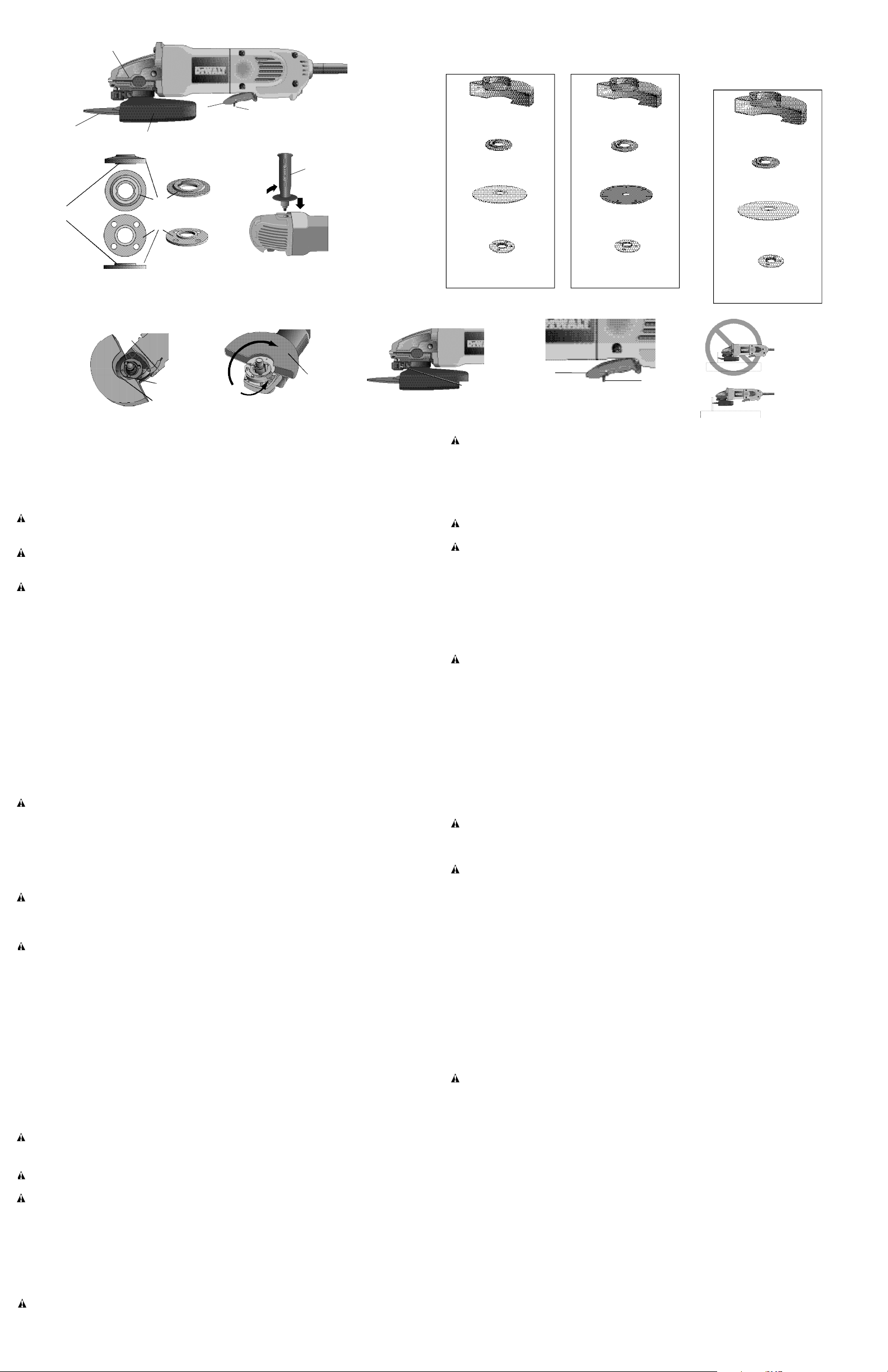
COMPONENTS (Fig. 1)
A . Paddle Switch F. 6" Cutting Wheel
B . L o c k - O f f Lever G . Anti-Lockup Backing Flange
C . Spindle Lock Button H . Threaded Clamp Nut
D . Spindle (not shown) I . G u a r d
E . Side Handle
ASSEMBLY
Attaching Side Handle (Fig. 1)
The side handle (E) can be fitted to either side of the gear case in the threaded holes, as
shown. Before using the tool, check that the handle is tightened securely.
OPERATION
Guards and Flanges
It is important to choose the correct guards and flanges to use with the cut-off tool accessories.
See Figure 2 for the correct accessories.
CAUTION: Accessories must be rated for at least the speed recommended on the tool
warning label. Wheels and other accessories running over rated accessory speed may fly
apart and cause injury. Every unthreaded accessory must have a 7/8" arbor hole. If it does not,
it may have been designed for a circular saw. Use only the accessories shown in Figure 2.
Accessory ratings must be above listed minimum wheel speed as shown on tool nameplate.
Mounting and Using Cutting Wheels (Type 1)
Cutting wheels include diamond wheels and abrasive discs. Abrasive cutting wheels for metal
and concrete use are available. Diamond cutting wheels for concrete cutting can also be used.
WARNING: A 4-1/2" closed, 2-sided cutting wheel guard is not included with this tool but is
required when using 4-1/2" cutting wheels. Failure to use proper flange and guard can result
in injury resulting from wheel breakage and wheel contact. See Figure 2 for more information.
MOUNTING GUARD (FIG. 3, 4)
CAUTION: Turn off and unplug the tool before making any adjustments or remov -
ing/installing attachments or accessories.
1 . Open the guard latch (J), and align the arrow (K) on the guard with the arrow (L) on the
hub. This will align the lugs with slots on the gear case cover. Position the guard facing
b a c k w a r d .
2 . Push the guard down until the guard lug engages and rotates freely in the groove on the
gear case hub.
3 . Rotate guard (I) into desired working position. The guard body should be positioned
between the spindle and the operator to provide maximum operator protection.
4 . Close the guard latch to secure the guard on the gear case cover. You should be unable
to rotate the guard by hand when the latch is in closed position. Do not operate grinder
with a loose guard or clamp lever in open position.
5 . To remove the guard, open the guard latch, rotate the guard so that the arrows are aligned
and pull up on the guard.
N O T E : The guard is pre-adjusted to the diameter of the gear case hub at the factory. If, after
a period of time, the guard becomes loose, tighten the adjusting screw (M) with the clamp lever
in the closed position (Fig. 5).
CAUTION: Do not tighten adjusting screw with clamp lever in open position. Undetectable
damage to guard or mounting hub may result.
MOUNTING CUTTING WHEELS
CAUTION: Turn off and unplug the tool before making any adjustments or removing
/installing attachments or accessories.
C A U T I O N : Matching diameter threaded backing flange and clamp nut (included with tool)
must be used.
1 . Place the anti-lockup backing flange on spindle with the pilot (N) facing up. Be sure the
backing flange recess is seated onto the flats of the spindle before placing wheel. The pilot
(N) on the backing flange will be against the wheel when the wheel is installed.
2 . Place the wheel on the backing flange, centering the wheel on the pilot.
3 . Install the threaded clamp nut with the pilot facing away from the wheel.
4 . Depress the spindle lock button and tighten clamp nut with a wrench.
5 . To remove the wheel, grasp the wheel and turn while depressing the spindle lock button.
WA R N I N G : When wheel is tightened, always make sure the clamp nut has rotated at least
1-1/2 turns to ensure proper thread engagement. Failure to do so could result in wheel dis mount and may result in injury.
SWITCH
C A U T I O N : Hold the side handle and body of the tool firmly to maintain control of the tool at
start up and during use and until the wheel stops rotating. Make sure the wheel has come to
a complete stop before laying the tool down.
PADDLE SWITCH (FIG. 6)
To turn the tool on, push the lock-off lever (B) toward the back of the tool, then depress the
paddle switch (A). The tool will run while the switch is depressed. Turn the tool off by releasing the paddle switch.
WA R N I N G: Do not disable the lock-off lever. If the lock-off lever is disabled, the tool may
start unexpectedly when it is laid down.
C A U T I O N : Allow the tool to reach full speed before touching tool to the work surface. Lift
the tool from the work surface before turning the tool off.
SPINDLE LOCK
The spindle lock pin is provided to prevent the spindle from rotating when installing or removing wheels. Operate the spindle lock pin only when the tool is turned off, unplugged from the
power supply, and has come to a complete stop. Do not engage the spindle lock while the tool
is operating because damage to the tool will result. To engage the lock, depress the spindle
lock button and rotate the spindle until you are unable to rotate the spindle further.
USING CUTTING WHEELS (FIG. 7)
WA R N I N G : Do not use cutting wheels for surface grinding applications because these
wheels are not designed for side pressures encountered with surface grinding. Wheel break age and injury may result.
1 . Allow tool to reach full speed before touching tool to work surface.
2 . Apply minimum pressure to work surface, allowing tool to operate at high speed. Cutting
rate is greatest when the tool operates at high speed.
3. Once a cut is begun and a notch is established in the workpiece, do not change the
angle of the cut. Changing the angle will cause the wheel to bend and may cause wheel
breakage.
4 . Remove the tool from work surface before turning tool off. Allow the tool to stop rotating
before setting it down.
MAINTENANCE
Cleaning
WARNING: Blow dust and grit out of the motor housing regularly using clean, dry com -
pressed air. Dust and grit containing metal particles often accumulate on interior surfaces and
could create an electrical shock hazard if not frequently cleaned out. A L WAYS WEAR SAFET Y
G L A S S E S .
WA R N I N G : Never use solvents or other harsh chemicals for cleaning the non-metallic parts
of the tool. Use a clean, dry cloth only.
Lubrication
DEWA LT tools are properly lubricated at the factory and are ready for use.
Motor Brushes
When brushes become worn, the tool will automatically stop and prevent damage to the motor.
Brush replacement should be performed by a DEWA LT authorized service center or other
qualified service personnel.
Repairs
To assure product SAFETY and RELIABILITY, repairs, maintenance and adjustments should
be performed by authorized service centers or other qualified service personnel. Always use
identical replacement parts.
ACCESSORIES
Recommended accessories for use with your tool are available at extra cost from your local
dealer or authorized service center. If you need assistance in locating any accessory for your
tool, contact: DEWA LT Industrial Tool Co., 701 East Joppa Road, Baltimore, MD 21286.
WARNING: The use of any other accessory not recommended for use with this tool could
be hazardous.
Three Year Limited Warranty
DEWA LT will repair, without charge, any defects due to faulty materials or workmanship for
three years from the date of purchase. For warranty repair information, call 1-800-4-DEWA LT.
This warranty does not apply to accessories or damage caused where repairs have been
made or attempted by others. This warranty gives you specific legal rights and you may have
other rights which vary in certain states or provinces.
In addition to the warranty, DEWA LT tools are covered by our:
1 YEAR FREE SERV I C E
DEWA LT will maintain the tool and replace worn parts caused by normal use, for free, any time
during the first year after purchase.
90 DAY M O N E Y BACK GUARANTEE
If you are not completely satisfied with the performance of your DEWA LT Power Tool, Laser,
or Nailer for any reason, you can return it within 90 days from the date of purchase with a
receipt for a full refund – no questions asked.
FREE WARNING LABEL R E P L A C E M E N T : If your warning labels become illegible or are
missing, call 1-800-4-DEWA LT for a free replacement.
I
L
K
6" Cutting Wheels
Meules à tronçonner
de 152 mm (6 po.)
Disco de corte
de 152 mm (6 pulg.)
4-1/2" Cutting Wheels
Meules à tronçonner de 114 mm (4-1/2 po.)
Disco de corte de 114 mm (4-1/2 pulg.)
Type 1 guard
protège-lame de type 1
Protector Tipo 1
backing flange
bride de soutien
pestaña de respaldo
abrasive cutting wheel
meule abrasive
disco de corte abrasivo
clamp nut
écrou de blocage
tuerca de fijación
diamond cutting wheel
meule diamant
disco de corte de diamante
M
J
A
B
FIG. 3
FIG. 4
FIG. 5
FIG. 6
FIG. 7
FIG. 2
H
A
B
C
F
G
I
E
FIG. 1
N
Type 1 guard
protège-lame de type 1
Protector Tipo 1
backing flange
bride de soutien
pestaña de respaldo
clamp nut
écrou de blocage
tuerca de fijación
Type 1 guard
protège-lame de type 1
Protector Tipo 1
backing flange
bride de soutien
pestaña de respaldo
clamp nut
écrou de blocage
tuerca de fijación
abrasive cutting wheel
meule abrasive
disco de corte abrasivo
Page 3

F r a n ç a i s
SI VOUS AVEZ DES QUESTIONS OU VOUS VOULEZ NOUS FAIRE PA R T DE VOS
C O M M E N TAIRES CONCERNANT C E T O U T I L OU TO U T AUTRE OUTIL D E WA L T,
COMPOSEZ SANS FRAIS LE : 1 8 0 0 433-9258. (1-800-4-DEWA LT ).
Règles de sécurité – Généralités
AV E R TISSEMENT : Lire, comprendre et suivre toutes les directives précisées
ci-dessous, y compris les consignes de sécurité, afin d’éviter les risques de choc
électrique, d’incendie ou de blessure grave.
CONSERVER CES DIRECTIVES
AIRE DE TRAVA I L
• L’aire de travail doit être propre et bien éclairée. Les établis encombrés et les endroits
sombres peuvent entraîner des accidents.
• Ne pas faire fonctionner des outils électriques dans des atmosphères explosives,
comme en présence de liquides, de gaz et de poussières inflammables. Les outils
électriques produisent des étincelles qui peuvent enflammer la poussière ou les vapeurs
• Tenir les enfants, les visiteurs ou toute autre personne à l’écart lorsqu’on utilise un
outil électrique; les distractions peuvent faire perdre la maîtrise de ce dernier.
MESURES DE SÉCURITÉ – ÉLECTRICITÉ
• Les outils mis à la terre doivent être branchés dans une prise correctement installée
et mise à la terre tel que l’indiquent les codes et règlements en vigueur. Ne jamais
retirer la broche de mise à la terre ou modifier la prise en aucune façon. Ne pas utilis er de fiche d’adaptation. Consulter un électricien qualifié s’il y a un doute en ce qui
concerne la mise à la terre de la prise. En cas de défaillance électrique ou de bris de
l’outil, la mise à la terre procure un chemin de faible résistance au courant afin de réduire
les risques de choc électrique. Cette protection ne s’applique qu’aux outils de classe I
(mis à la terre).
• Les outils à double isolation sont munis d’une fiche polarisée (c’est-à-dire que l’une
des lames est plus large que l’autre), laquelle ne peut être raccordée qu’à une prise
polarisée et ce, dans un seul sens; on doit l’inverser si on est incapable de l’enfon cer complètement. Si la fiche ne s’adapte toujours pas, on doit faire appel à un élec tricien qualifié pour qu’il installe la prise appropriée. On ne doit jamais modifier la
f i c h e . La double isolation élimine le besoin d’installer un cordon d’alimentation trifilaire
et un système d’alimentation électrique pourvus d’une mise à la terre; seuls les outils de
classe II (à double isolation) sont munis d’une telle protection.
• Éviter tout contact entre le corps et les éléments mis à la terre, comme les tuyaux,
les radiateurs, les cuisinières et les réfrigérateurs, afin de réduire les risques de choc
é l e c t r i q u e .
• Ne pas utiliser l’outil électrique dans des endroits mouillés, ni l’exposer à la pluie;
l’infiltration d’eau à l’intérieur de l’outil augmente les risques de choc électrique.
• Ne pas utiliser le cordon de manière abusive; on ne doit pas transporter l’outil en le
tenant par le cordon, ou utiliser ce dernier pour le débrancher. On doit tenir le cor don à l’écart des sources de chaleur, de l’huile, des bords tranchants ou des pièces
mobiles. Remplacer immédiatement les cordons endommagés, car ces derniers aug -
mentent les risques de choc électrique.
• Lorsqu’on utilise un outil électrique à l’extérieur, on ne doit utiliser que des rallonges
conçues pour cet usage, comme celles de type « W- A » ou « W », afin de réduire les
risques de choc électrique. S’assurer que la rallonge est en mesure de porter le courant
nécessaire à l’outil. Une rallonge de calibre inférieur entraînera une chute de tension se
traduisant par une perte de puissance et une surchauffe. Le tableau ci-dessous illustre les
calibres que l’on doit utiliser selon la longueur de la rallonge et l’intensité nominale indiquée
sur la plaque signalétique. En cas de doute, utiliser le calibre suivant. Plus le calibre est
petit, plus la rallonge peut porter de courant.
Calibre de fil minimum recommandé pour les rallonges
Longueur totale de la rallonge
25 pi 50 pi 75 pi 100 pi 125 pi 150 pi 175 pi
7,6 m 15,2 m 22,9 m 30,5 m 38,1 m 45,7 m 53,3 m
Calibre AW G
18 18 1 6 16 14 1 4 1 2
SÉCURITÉ PERSONNELLE
• Rester vigilant en tout temps et faire preuve de jugement lorsqu’on utilise un outil
électrique. Ne pas utiliser l’outil lorsqu’on est fatigué ou sous l’influence de drogues,
d’alcool ou de médicaments, car un moment d’inattention pourrait entraîner des
blessures graves.
• Porter des vêtements appropriés. Ne pas porter des vêtements amples ou des
bijoux. Couvrir ou attacher les cheveux longs. Garder les cheveux, les vêtements,
les bijoux et les gants éloignés des pièces mobiles, car ceux-ci peuvent s’y coincer. S e
tenir éloigné des évents puisque ces derniers pourraient camoufler des pièces mobiles.
• Éviter les démarrages accidentels; s’assurer que l’interrupteur est en position d’ar -
rêt avant de brancher l’outil. Ne pas transporter l’outil en laissant le doigt sur l’interrup teur ni le brancher lorsque l’interrupteur est en position de marche, car cela pourrait causer
un accident.
• Retirer les clés de réglage avant de démarrer l’outil.Une clé laissée sur une pièce rota -
tive pourrait entraîner des blessures.
• Ne pas trop étendre les bras. Les pieds doivent rester ancrés fermement au sol afin
de maintenir son équilibre en tout tempset de mieux maîtriser l’outil dans des situations
i m p r é v u e s .
• Utiliser le matériel de sécurité approprié; toujours porter des lunettes de protection.
Porter un masque anti-poussières, des chaussures antidérapantes, un casque de sécurité
ou des protecteurs auditifs lorsque la situation le requiert.
U T I L I S ATION ET ENTRETIEN DE L’ O U T I L
• Fixer et soutenir la pièce sur une plate-forme stable au moyen d’une bride de serrage
ou de tout autre dispositif semblable. La pièce est instable lorsqu’on la retient manuelle -
ment ou qu’on l’appuie contre le corps, ce qui pourrait faire perdre la maîtrise de l’outil.
• Ne pas forcer l’outil ni l’utiliser pour des travaux autres que ceux pour lesquels il a
été conçu. Pour obtenir de meilleurs résultats et prévenir les risques de blessure, laisser
l’outil couper à la vitesse pour laquelle il a été conçu.
• Ne pas utiliser l’outil lorsque l’interrupteur marche-arrêt ne fonctionne pas. Tout outil
qui ne peut être commandé au moyen de l’interrupteur est dangereux et doit être réparé.
• Débrancher l’outil de la source d’alimentation électrique avant d’effectuer un
réglage, de changer les accessoires ou de ranger l’outil; ces mesures de sécurité
préventives réduisent les risques de démarrage accidentel.
• Lorsqu’on n’utilise pas l’outil, le ranger hors de la portée des enfants ou des per -
sonnes non qualifiées. Les outils sont dangereux entre les mains de personnes inex p é r i m e n t é e s .
• Bien entretenir l’outil; s’assurer qu’il est toujours bien propre et aiguisé. Les outils
bien entretenus et dont les bords sont bien tranchants sont moins susceptibles de rester
coincés et sont plus faciles à maîtriser.
• Vérifier les pièces mobiles afin de s’assurer qu’elles sont bien alignées et qu’elles
ne restent pas coincées. Vérifier également les pièces afin de s’assurer qu’il n’y a
aucun bris ni aucune autre condition susceptible de nuire au bon fonctionnement de
l’outil. Faire réparer l’outil si ce dernier est endommagé avant de s’en servir à nou v e a u , car les accidents sont souvent causés par des outils mal entretenus.
• N’utiliser que les accessoires recommandés par le fabricant pour le modèle con c e r n é . Un accessoire destiné à un outil particulier peut devenir dangereux lorsqu’il est util -
isé avec un autre.
E N T R E T I E N
• L’outil doit être entretenu par le personnel qualifié seulement; toute maintenance
effectuée par une personne non qualifiée pourrait entraîner des risques de blessure.
• Lors de l’entretien, n’utiliser que des pièces de rechange identiques et suivre les
directives précisées à la section « Entretien » du présent guide afin de prévenir les
risques de choc électrique ou de blessure.
Régles de sécurité particuliéres additionnelles pour
tronçonneuses
• Utiliser toujours le dispositif de protection qui convient à la meule afin de protéger
l’opérateur des fragments pouvant être projetés par une meule brisée ou d’empêcher tout
contact avec la meule.
• La vitesse des accessoires doit correspondre à la vitesse minimale recommandée
indiquée sur l’étiquette d’avertissement de l’outil, car les meules et les accessoires qui
sont réglés à une vitesse trop élevée peuvent se briser et occasionner des blessures
lorsque des fragments de métal sont projetés. S’assurer que l’intensité nominale des
accessoires utilisés est supérieure à la vitesse minimum des meules indiquée sur la plaque
s i g n a l é t i q u e .
• Tenir l’outil par les surfaces isolées prévues à cette fin lorsqu’il risque d’entrer en
contact avec des fils cachés ou son propre cordon, car de tels contacts peuvent met -
tre les pièces métalliques de l’outil sous tension, engendrant des risques de choc élec t r i q u e .
• Ne pas utiliser de meules boisseau coniques (type 11) avec cet outil. L’utilisation d’ac cessoires inadéquats pose des risques de blessure.
• N’utiliser que des meules à tronçonner d’une épaisseur maximum de 152 mm (6 po.)
sur 3mm (1/8 po.) avec cet outil. Le fait d’utiliser d’autres accessoires n’est pas recom -
mandé et pose des risques de blessure ou d’endommager l’outil.
• Toujours utiliser des protège-lames de type 1 avec les meules à tronçonner. Le pro -
tège-lame protège l’utilisateur contre toute projection de fragments et tout contact avec la
meule. Les protège-lames de type 1 couvrent les deux faces de la meule offrant ainsi une
protection maximum lors de leur utilisation.
• TOUJOURS PORTER DES LUNETTES DE PROTECTION LORSQU’ON UTILISE CET
O U T I L .
• L’utilisation d’accessoires non spécifiés dans le présent guide n’est pas recom mandée et peut présenter un danger. L’utilisation d’un compresseur en vue de faire fonc -
tionner l’outil à une vitesse supérieure à la vitesse nominale recommandée constitue un
emploi abusif de l’outil.
• Ne jamais utiliser de lames pour scie circulaire avec cet outil, ni de lames dentées,
afin d’éviter les risques de blessure grave.
• Avant d’utiliser un accessoire recommandé, le vérifier afin de s’assurer qu’il n’y a
aucun bris ni fissure. Si on y trouve de tels défauts, mettre l’accessoire au rebut.
Inspecter également l’accessoire chaque fois qu’il subit un choc, car un accessoire
défectueux risque de briser la meule. Ne pas reposer l’outil sur la meule.
• Lorsqu’on démarre l’outil (après y avoir installé une meule neuve ou de rechange)
ou qu’on doute de son état de fonctionnement,se tenir dans un endroit bien protégé
et le faire fonctionner pendant une minute, car si l’outil est fissuré ou brisé, i l d e v r a i t
éclater en moins d’une minute. Ne jamais démarrer un outil lorsque quelqu’un, y compris
l ’ o p é r a t e u r , se tient directement devant lui.
• Éviter de faire rebondir la meule durant son fonctionnement ou de l’utiliser sans
m é n a g e m e n t . Si la meule subit de tels traitements, arrêter l’outil et inspecter cette
d e r n i è r e .
• Orienter les étincelles dans le sens opposé de l’opérateur ou de toute autre person -
ne se trouvant à proximité, ainsi que des matériaux inflammables. Des étincelles peu vent se produire pendant la coupe, et poser ainsi des risques de brûlure ou d’incendie.
• Toujours utiliser la poignée latérale. Fixer la poignée solidement. La poignée latérale
doit toujours être utilisée pour maîtriser l’outil en tout temps.
• Ne jamais couper dans une zone pouvant camoufler des tuyaux ou des fils élec -
triques afin d’éviter les risques de blessure grave.
• Bien nettoyer l’outil périodiquement, surtout après l’avoir utilisé longuement, car la
poussière et les particules métalliques tendent à s’accumuler sur les surfaces internes et
peuvent entraîner des risques de choc électrique.
• Ne pas utiliser cet outil pendant des périodes prolongées. Les vibrations causées par
l’action de fonctionnement de l’outil peuvent blesser en permanence les doigts, les mains
et les bras. Porter des gants pour amortir les vibrations, faire des pauses fréquentes et lim iter le temps d’utilisation quotidien de l’outil.
• L’étiquette apposée sur l’outil peut afficher les symboles suivants :
V . . . . . . . . . . . . . .v o l t s A . . . . . . . . . . . . . .a m p è r e s
Hz . . . . . . . . . .h e r t z W . . . . . . . . . . . .w a t t s
m i n . . . . . . . . . .m i n u t e s . . . . . . . . . . . .courant alternatif
. . . . . . . .courant continu
n
o. . . . . . . . . . . . . .vitesse à vide aucune option à vide
. . . . . . . . . . . .construction de classe II . . . . . . . . . . . .borne de terre
. . . . . . . . . . . .symbole d’avertissement … / m i n . . . . . .to urs par minute
s p p m . . . . . . . .surface de ponçage par minute
Causes du rebond et mesures préventives
• Le rebond est une réaction soudaine de l’outil causée par une lame pincée, bloquée ou mal
alignée, occasionnant la perte de maîtrise de la tronçonneuse qui se soulève et se détache
de la pièce en direction de l’opérateur
• Lorsque une meule est pincée ou bloquée dans le matériau, elle cale et le moteur en réac tion provoque un rebond arrière de l’appareil vers l’utilisateur.
• Le rebond découle d’une mauvaise utilisation ou du mauvais fonctionnement de l’outil; on
peut l’éviter en prenant les précautions suivantes :
• Tenir fermement l’outil des deux mains et placer le corps et les bras de manière à
pouvoir maîtriser les effets du rebond; le rebond peut être maîtrisé si l’opérateur
prend les précautions nécessaires.
• Lorsque la meule se coince ou qu’on veut interrompre une coupe pour quelque rai -
son que ce soit, relâcher l’interrupteur à gâchette et maintenir l’outil immobile dans
la pièce, jusqu’à ce que la meule s’arrête complètement. Ne jamais tenter de sortir
l’outil hors de l’entaille ou de le tirer vers soi avant que la meule ne se soit immo bilisée complètement afin d’éviter le rebond. Vérifier la pièce afin de déterminer la
cause du coincement et de prendre les mesures correctives qui s’imposent.
• S’assurer que la meule n’est pas engagée dans le matériau avant de remettre en
marche la tronçonneuse. Une meule coincée peut sauter ou faire un rebond arrière
hors du matériau lorsque l’outil est remis en marche.
• Soutenir les grands panneaux afin d’éviter autant que possible de coincer la
meule et d’engendrer un rebond. Les grands panneaux tendent à s’affaisser sous leur
poids et doivent être soutenus de chaque côté, près de la ligne de coupe et du bord du
p a n n e a u .
AV E R TISSEMENT : Certains outils électriques, tels que les sableuses, les scies, les
meules, les perceuses ou certains autres outils de construction, peuvent produire de la pous sière contenant des produits chimiques susceptibles d’entraîner le cancer, des malformations
congénitales ou pouvant être nocifs pour le système reproductif. Parmi ces produits chim iques, on retrouve :
• le plomb dans les peintures à base de plomb,
• la silice cristalline dans les briques et le ciment et autres produits de maçonnerie,
Page 4

E s p a ñ o l
Instrucciones de seguridad generales
¡ A D V E R TENCIA! Lea todas las instrucciones hasta comprenderlas. N o
ajustarse a las instrucciones siguientes puede ser causa de choque eléctrico,
incendio o lesiones graves.
CONSERVE ESTAS INSTRUCCIONES
Á R E A DE TRABAJO
• Mantenga el área de trabajo limpia y bien iluminada. Las bancadas desordenadas y
las zonas oscuras propician los accidentes.
• No opere herramientas eléctricas en atmósferas explosivas, como en presencia de
líquidos, gases o polvos inflamables. Las herramientas eléctricas producen chispas que
pueden originar la ignición del polvo o los vapores.
• Mientras opere una herramienta eléctrica, mantenga lejos a los observadores, niños
y visitantes. Las distracciones pueden ocasionar que pierda el control
SEGURIDAD ELÉCTRICA
• Las herramientas con conexión a tierra deben conectarse a una toma de corriente
debidamente instalada y con conexión a tierra, de acuerdo con todos los códigos y
ordenanzas aplicables. Nunca quite la pata de conexión a tierra ni modifique el
enchufe en ninguna manera. No emplee ningún adaptador para enchufes. Si tiene
alguna duda acerca de si la toma de corriente está debidamente conectada a tierra,
consulte a un electricista calificado. Si las herramientas presentasen fallas eléctricas o
averías, la conexión a tierra ofrece una vía de baja resistencia para alejar la corriente eléctri ca del usuario. Sólo es aplicable a las herramientas de Clase I (con conexión a tierra).
• Las herramientas con doble aislamiento están equipadas con una clavija polarizada
(una pata es más ancha que la otra). Esta clavija se acoplará a un enchufe polariza do de una sola manera. Si la clavija no se acopla al contacto, inviértala. Si aún así
no se ajusta, comuníquese con un electricista cualificado para que instale un
• l’arsenic et le chrome dans le bois de sciage ayant subi un traitement chimique (comme
l’arséniate de cuivre et de chrome).
Le risque associé à de telles expositions varie selon la fréquence avec laquelle on effectue
ces travaux. Pour réduire l’exposition à de tels produits, il faut travailler dans un endroit bien
aéré et utiliser le matériel de sécurité approprié, tel un masque anti-poussières spécialement
conçu pour filtrer les particules microscopiques.
• Éviter tout contact prolongé avec la poussière soulevée par cet outil ou autres out ils électriques. Porter des vêtements de protection et nettoyer les parties exposées
du corps à l’eau savonneuse. S’assurer de bien se protéger afin d’éviter d’absorber par
la bouche, les yeux ou la peau des produits chimiques nocifs.
AV E R TISSEMENT : Cet outil peut produire et répandre de la poussière susceptible de
causer des dommages sérieux et permanents au système respiratoire. Toujours utiliser un
appareil respiratoire anti-poussières approprié approuvé par le NIOSH ou l’OSHA. Diriger les
particules dans le sens opposé du visage et du corps.
MISE EN GARDE : Prendre des précautions supplémentaires pour les travaux de coin, la
tronçonneuse pourrait faire un mouvement soudain et brusque si la meule ou tout autre acces soire entrait en contact avec une surface secondaire ou un bord.
MISE EN GARDE : Porter un appareil de protection personnel anti-bruit approprié
durant l’utilisation. Sous certaines conditions et selon la durée d’utilisationpendant toute la
durée de l’utilisation, le bruit émanant de ce produit pourrait contribuer à la perte d’audition.
DESCRIPTION (fig. 1)
A . Interrupteur à gâchette F. Meules à tronçonner de 152 mm (6 po.)
B . Levier de verrouillage G . Bride de soutien antiblocage
C . Bouton de verrouillage de la broche H . Écrou de blocage fileté
D . Broche (non-illustrée) I . P r o t è g e - l a m e
E . Poignée latérale
ASSEMBLAGE
Installation de la poignée latérale (fig. 1)
La poignée latérale (E), comme illustré, peut être installée sur l’un ou l’autre côté du carter
d’engrenage dans les orifices filetés. Avant utilisation de l’outil, vérifier que la poignée est
solidement arrimée.
FONCTIONNEMENT
Protège-lames et brides
Il est important de choisir des protège-lames et brides conformes aux accessoires de la
tronçonneuse. Se reporter à la figure 2 pour la liste des accessoires conformes.
MISE EN GARDE : La vitesse nominale des accessoires doit être équivalente ou
supérieure à celle recommandée sur l’étiquette d’avertissement de l’outil. Une meule ou tout
autre accessoire tournant à une vitesse supérieure à sa vitesse nominale peut se désintégrer
et poser des risques de blessure. Tout accessoire non fileté doit comporter un orifice d’arbre de
20 mm (7/8 po.). Si ce n’est pas le cas, il peut avoir été conçu pour une scie circulaire. N’utiliser
que des accessoires figurant sur la liste en Figure 2. L’intensité nominale des accessoires util isés doit être supérieure à la vitesse minimum des meules indiquée sur la plaque signalétique.
Installation et utilisation des meules á tronçonner de
type 1
Ces meules à tronçonner comprennent les meules diamant et les meules abrasives. Des
meules abrasives pour métal et béton sont aussi disponibles. Des meules diamant pour
couper le béton peuvent aussi être utilisées.
AV E R TISSEMENT : Un protège-lame de 114 mm (4-1/2 po.) obtus à deux faces, non inclus
avec cet outil, est requis lors de l’utilisation de ce dernier avec des meules à tronçonner de
114 mm (4-1/2 po.). Le fait de ne pas utiliser de brides ou de protège-lames adéquates pose
des risques de blessure dus à une rupture de la meule ou un contact avec cette dernière. Se
reporter en figure 2 pour plus d’informations.
I N S TA L L A TION DU PROTÈGE-LAME (FIG. 3, 4)
MISE EN GARDE : Arrêter et débrancher l’outil avant d’effectuer un réglage ou de
retire /d’installer une pièce ou un accessoire.
1 . Ouvrir le mécanisme de verrouillage (J), et aligner la flèche (K) sur le protège-lame avec
celle du moyeu (L). Cela alignera les pattes avec les rainures du couvercle du carter d’engrenage. Orienter le protège-lame vers l’arrière.
2 . Enfoncer le protège-lame jusqu’à ce que sa patte s’enclenche et tourne librement dans la
rainure du carter d’engrenage.
3 . Faire tourner le protège-lame (I) jusqu’à la position de travail désirée. Le corps du protège-
lame devrait se trouver entre la broche et l’utilisateur pour offrir une protection maximale
à ce dernier.
4 . Fermer le mécanisme de verrouillage pour arrimer solidement le protège-lame sur le
carter d’engrenage. Il devrait être maintenant impossible de faire tourner le protège-lame
à la main lorsque le mécanisme de verrouillage est enclenché. Ne pas utiliser la meule si
le protège-lame est lâche ou si son mécanisme de verrouillage est ouvert.
5 . Pour retirer le protège-lame, ouvrir le mécanisme de verrouillage, faire tourner le protège-
lame pour aligner les flèches puis tirer sur celui-ci.
REMARQUE : Le protège-lame est ajusté d’usine au diamètre du moyeu de la broche. Si,
après un certain temps, le protège-lame se mettait à bouger, resserrer la vis de réglage (M)
alors que le levier de serrage est en position fermée (fig. 5).
MISE EN GARDE : Ne pas resserrer la vis de réglage si le levier de serrage est en posi -
tion ouverte. Le protège-lame ou le moyeu d’assemblage pourrait subir des dommages
i n d é c e l a b l e s .
I N S TA L L A TION DES MEULES À TRONÇONNER
MISE EN GARDE : Arrêter et débrancher l’outil avant d’effectuer un réglage ou de retire
/d’installer une pièce ou un accessoire.
MISE EN GARDE : Toujours utiliser des brides de soutien et écrous de blocage filetés
(inclus avec l’outil) de même diamètre.
1 . Installer la bride de soutien antiblocage sur la broche avec le pilote (N) sur le dessus.
S’assurer que l’interstice de la bride de soutien est bien assis sur le plat de la broche avant
d’installer la meule. Le pilote (N) sur la bride de soutien se retrouvera contre la meule
après installation de cette dernière.
2 . Placer la meule sur la bride de soutien, en la centrant sur le pilote.
3 . Installer l’écrou de blocage fileté avec le pilote orienté à l’opposé de la meule.
4 . Appuyer sur le bouton de verrouillage de la broche et serrer l’écrou avec une clé.
5 . Pour retirer la meule, attraper la meule et la tourner tout en poussant sur le bouton de ver-
rouillage de la broche.
AV E R TISSEMENT : Lorsque la meule est serrée, s’assurer que l’écrou de blocage a
tourné d’au moins un tour et demi pour que le filetage soit bien engagé. Dans le cas contraire,
la meule pourrait se dégager et poser des risques de dommages corporels.
INTERRUPTEUR
MISE EN GARDE : Maintenir la poignée latérale et le corps de l’outil fermement pour
garder le contrôle de l’outil au démarrage et pendant toute son utilisation, et ce, jusqu’à arrêt
complet de la meule. Avant de poser l’outil, s’assurer que la meule s’est complètement arrêtée
de tourner.
INTERRUPTEUR À GÂCHETTE (FIG. 6)
Pour mettre l’outil en marche, pousser le levier de verrouillage (B) vers l’arrière de l’outil, puis
appuyer sur l’interrupteur à gâchette (A). L’outil fonctionnera tant que l’interrupteur restera
appuyé. Pour arrêter l’outil, relâcher l’interrupteur à gâchette.
AV E R TISSEMENT : Ne pas désactiver le levier de verrouillage. Si le levier de verrouillage
était désactivé, l’outil pourrait démarrer accidentellement alors qu’il est posé.
MISE EN GARDE : Laisser l’outil gagner sa vitesse maximum avant de le mettre en con -
tact avec la surface à travailler. Retirer l’outil de la pièce à travailler avant de l’arrêter.
B O U T ON DE VERROUILLAGE DE LA BROCHE
Le bouton de verrouillage de la broche est destiné à empêcher la broche de tourner lors de
l’installation ou du retrait de la meule. N’utiliser le bouton de verrouillage de la broche que
lorsque l’outil est à l’arrêt, débranché du secteur, et après arrêt complet du moteur. Ne jamais
activer le bouton de verrouillage de la broche lors du fonctionnement de l’outil, ce dernier subirait des dommages. Pour actionner le verrouillage, appuyer sur le bouton de verrouillage de
la broche puis faire tourner la broche jusqu’à arrêt complet.
U T I L I S ATION DES MEULES À TRONÇONNER (FIG. 7)
AV E R TISSEMENT : Ne pas utiliser les meules à tronçonner pour des travaux de meulage
car elles ne sont pas conçues pour subir les pressions latérales nécessaires au meulage de
finition. La meule pourrait se briser et poser des risques de dommages corporels.
1 . Laisser l’outil gagner sa vitesse maximum avant de le mettre en contact avec la surface à
t r a v a i l l e r.
2 . Appliquer un minimum de pression sur la surface à travailler, pour permettre à l’outil de
fonctionner à sa vitesse maximum. Le rythme de coupe est supérieur lorsque l’outil fonctionne à grande vitesse.
3 . Ne pas changer l’angle de coupe une fois que cette dernière est commencée et qu’une
entaille existe dans la pièce à travailler. Cela pourrait faire arquer la meule et la casser.
4 . Retirer l’outil de la pièce à travailler avant de l’arrêter. Laisser l’outil s’arrêter complètement
de tourner avant de le poser.
ENTRETIEN
Nettoyage
AV E R TISSEMENT : Éliminer régulièrement poussières et débris du carter du moteur à
l’aide d’un jet d’air comprimé net et sec. Des poussières ou débris contenant des particules
métalliques s’accumulent souvent sur les surfaces internes posant ainsi de sérieux risques de
chocs électriques. TOUJOURS PORTER DES LUNETTES DE SÉCURITÉ
AV E R TISSEMENT : Ne jamais utiliser de solvants ou d’autres produits chimiques pour net -
toyer les pièces non métalliques de l’outil; ne les nettoyer qu’au moyen d’un linge propre et sec.
Lubrification
Les outils DEWA LT sont lubrifiés en usine et sont donc prêts à utiliser
Balais de moteur
Lorsque les balais sont usés, l’outil s’arrête automatiquement, empêchant ainsi tout dommage
au moteur. Ces balais doivent être remplacés dans les centres de service autorisés DEWA LT
ou par du personnel qualifié.
Réparations
Pour assurer la SÉCURITÉ et la FIABILITÉ de ce produit, toutes les opérations de réparation,
d’entretien et de réglage doivent être effectuées dans un centre de service autorisé ou par du
personnel qualifié; on ne doit utiliser que des pièces de rechange identiques.
ACCESSOIRES
Les accessoires recommandés pour cet outil sont vendus séparément chez les dépositaires
locaux ou dans les centres de service autorisés. Pour obtenir plus d’information sur les accessoires, communiquer avec DEWA LT Industrial Tool Co., 701 East Joppa Road, Baltimore, MD
21286, aux États-Unis.
AV E R TISSEMENT : L’utilisation de tout autre accessoire non recommandé avec cet outil
pourrait être dangereux.
Garantie limitée de trois ans
DEWA LT réparera, sans frais, tout produit défectueux causé par un défaut de matériel ou de
fabrication pour une période de trois ans à compter de la date d’achat. Pour obtenir de plus
amples renseignements sur les réparations couvertes par la présente garantie, composer le
1 800 433-9258 (1-800-4-DEWA LT). Cette garantie ne s’applique pas aux accessoires et ne
vise pas les dommages causés par des réparations effectuées par un tiers. Cette garantie
confère des droits légaux particuliers à l’acheteur, mais celui-ci pourrait aussi bénéficier
d’autres droits variant d’un état ou d’une province à l’autre.
En plus de la présente garantie, les outils DEWA LT sont couverts par notre:
C O N T R AT D’ENTRETIEN GRATUIT D’UN A N
DEWA LT entretiendra l’outil et remplacera les pièces usées au cours d’une utilisation normale
et ce, gratuitement, pendant une période d’un an à compter de la date d’achat, et la
GARANTIE DE REMBOURSEMENT DE 90 JOURS
Si l’acheteur n’est pas entièrement satisfait, pour quelque raison que ce soit, du rendement de
l’outil électrique, du laser ou de la cloueuse DEWA LT, celui-ci peut le retourner, accompagné
d’un reçu, dans les 90 jours à compter de la date d’achat, pour obtenir un remboursement
intégral, sans aucun problème.
REMPLACEMENT GRATUIT DE L’ÉTIQUETTE D’AVERTISSEMENT : En cas de perte ou
d’endommagement des étiquettes d’avertissement, composer le 1 800 433-9258 (1-800-4DEWA LT). Afin d’en obtenir de nouvelles sans frais.
Page 5

se debe inspeccionar el accesorio siempre cuando la herramienta pueda haberse
c a í d o . Las fallas pueden provocar la rotura del disco. No coloque la unidad sobre el disco
cuando la ponga a un lado.
• Cuando arranque la herramienta. con un disco nuevo o de repuesto instalado o si no
está seguro de la condición del disco, sostenga la herramienta en un área bien pro tegida y déjela que ande por un minuto. Si el disco tiene una cuarteadura o falla no
detectada, debiera reventar en menos de un minuto. Nunca arranque la herramienta. con
una persona situada en línea con el disco, incluyendo al operador.
• Evite rebotar el disco o tratarlo bruscamente. Si ello sucediera, detenga la herramien -
ta e inspeccione el disco para ver si presenta cuarteaduras o fallas.
• Dirija las chispas en dirección opuesta al operador, observadores y materiales
inflamables. El corte puede producir chispas. Las chispas pueden provocar quemaduras
o incendios.
• Siempre use el mango lateral. Ajuste el mango firmemente. El mango lateral debería
ser siempre utilizado para mantener el control de la herramienta en todo momento.
• Nunca corte en un área que podría contener cables eléctricos o tuberías. P o d r í a
resultar en lesiones graves.
• Limpie su herramienta con frecuencia, especialmente después de usos prolonga d o s . El polvo y la arenilla que contienen partículas metálicas se acumulan con frecuencia
en las superficies interiores y podrían ocasionar peligro de descarga eléctrica.
• No opere esta herramienta durante períodos largos de tiempo. La vibración causada
por la acción de operación de esta herramienta puede causar lesiones permanentes a los
dedos, las manos y los brazos. Utilice guantes para una mayor amortiguación, tome des cansos frecuentes y limite el tiempo de uso diario.
• La etiqueta de la herramienta puede incluir los siguientes símbolos:
V . . . . . . . . . . . . . .v o l t i o s A . . . . . . . . . .a m p e r i o s
H z . . . . . . . . . . . .h e r t z i o s W . . . . . . . . . .v a t i o s
m i n . . . . . . . . . .m i n u t o s . . . . . . . .corriente alterna
. . . . . . . .corriente directa
n
o .........velocidad sin carga
. . . . . . . . . . . .construcción de Clase II . . . . . . . . . .te rminal con conexión a tierra
. . . . . . . . . . . .símbolo de alerta de seguridad
. . . / m i n . . . . . ..re voluciones por minuto
s f p m . . . . . . . .pies de superficie por minuto
Causas y Prevención de Rebote por Parte del Operador
• El rebote es una reacción repentina a un disco de corte trabado o mal alineado lo cual
causa que la herramienta de corte pierda el control y que se levante y rebote contra la pieza
de trabajo en la dirección del operador.
• Cuando el disco se pincha o atasca demasiado en la pieza de trabajo, el disco se detiene
y la reacción del motor lleva a la unidad a saltar rápidamente hacia atrás, en dirección al
o p e r a d o r .
• El rebote es el resultado del mal uso de la herramienta o de procedimientos o condi -
ciones de operación incorrectos y puede ser evitado al tomar las precauciones debidas,
enumeradas a continuación:
• Sujete la unidad firmemente con ambas manos y sitúe su cuerpo y brazo de modo
que pueda resistir la fuerza del rebote. La fuerza del rebote puede ser controlada por
el operador si se toman las precauciones debidas.
• Cuando el disco se trabe o cuando el corte deba ser interrumpido por cualquier
motivo, suelte el gatillo y sostenga la unidad sin moverla, dentro del material
hasta que el disco se detenga completamente. Nunca intente quitar la unidad de
la pieza de trabajo o tirar de la unidad hacia atrás mientras el disco esté en
movimiento, pues podría rebotar. Investigue y tome medidas correctivas para elimi -
nar la causa del trabado de la sierra.
• Cuando vuelva a arrancar la herramienta de corte en la pieza de trabajo, revise
que el disco no esté encajado en el material. Si el disco se atasca, puede que salte
o rebote de la pieza de trabajo al volver a arrancar la herramienta.
• Soporte paneles grandes para minimizar el riesgo de trabado y rebote del disco.
Los paneles grandes tienden a hundirse en el medio, por su propio peso. Se debe colo car soporte bajo el panel en ambos costados, cerca de la línea del corte y del borde del
p a n e l .
A D V E RT E N C I A : Parte del polvo generado al lijar, serrar, esmerilar y taladrar, así como al
realizar otras actividades del sector de la construcción, contienen productos químicos que
pueden producir cáncer, defectos congénitos u otras afecciones reproductivas. Ejemplos de
esas substancias químicas son:
• plomo procedente de pinturas a base de plomo,
• óxido de silicio cristalino procedente de ladrillos, cemento y otros productos
de mampostería, y
• arsénico y cromo procedentes de madera tratada químicamente (CCA).
El peligro derivado de estas exposiciones que usted enfrente varía en función de la frecuencia
con que se realice este tipo de trabajo. Para reducir la exposición a esas sustancias químicas:
trabaje en una zona bien ventilada y llevando equipos de seguridad aprobados, como mascar illas antipolvo especialmente diseñadas para filtrar partículas microscópicas.
• Evite el contacto prolongado con el polvo procedente del lijado, serrado, esmerila do y taladrado eléctricos, así como de otras actividades del sector de la construc ción. Lleve ropa protectora y lave con agua y jabón las zonas expuestas. Si permite
que el polvo se introduzca en la boca u ojos o quede sobre la piel, puede favorecer la
absorción de productos químicos peligrosos.
A D V E RTENCIA: El uso de esta herramienta puede generar o dispersar polvo lo cual
puede causar lesiones respiratorias serias y permanentes y otros tipos de lesión. Siempre use
protección respiratoria aprobada por NIOSH/OSHA para la exposición al polvo. Dirija las
partículas en dirección opuesta a su cara y cuerpo
PRECAUCIÓN: Tenga mucho cuidado cuando trabaje en una esquina porque la her -
ramienta de corte puede moverse repentina y bruscamente cuando el disco u otro accesorio
haga contacto con una superficie secundaria o borde de una superficie.
PRECAUCIÓN: Utilice una protección auditiva apropiada durante el uso. En determi -
nadas condiciones y con utilizaciones prolongadas, el ruido generado por este producto
puede favorecer la pérdida de audición.
COMPONENTES (Fig. 1)
A . Conmutador de palanca F. Disco de corte de 152 mm (6 pulg.)
B . Palanca de bloqueo en off G . Pestaña de respaldo anti bloqueo
C . Botón de bloqueo del eje H . Tuerca de fijación con hilo
D . Eje (no ilustrado) I . P r o t e c t o r
E . Mango lateral
ENSAMBLAJE
Ensamblaje del mango lateral (Fig. 1)
El mango lateral (E) puede ser instalado a cualquiera de los dos lados del cárter en los orificios con hilo, como aparece ilustrado. Antes de utilizar esta herramienta, revise que el mango
esté firmemente ajustado.
OPERACIÓN
Protectores y pestañas
Es importante escoger los protectores y las pestañas correctos para usar con los accesorios
de la herramienta de corte. Ver Figura 2 para los accesorios correctos.
PRECAUCIÓN: Los accesorios deben ser especificados como mínimo para la velocidad
recomendada en la etiqueta de advertencia de la herramienta. Los discos y otros accesorios
que operan a velocidades sobre la velocidad nominal del accesorio pueden salir despedidos y
causar lesiones. Cada accesorio sin hilo debe tener un orificio para un mandril de 20 mm (7/8
pulg.). Si no, puede que haya sido diseñado para una sierra circular. Use sólo los accesorios
ilustrados en la Figura 2. Las especificaciones de los accesorios deben encontrarse a una
velocidad de disco superior a la mínima registrada en la placa nominal de la herramienta.
Montaje y uso de discos de corte (Tipo 1)
Los discos de corte incluyen discos de diamante y discos abrasivos. Los discos abrasivos de
corte para cortar metal y concreto también se encuentran disponibles. Los discos de corte de
diamante para cortar concreto también pueden ser utilizadas.
enchufe polarizado apropiado. Nunca cambie la clavija. El doble aislamiento e l i m i n a
la necesidad de cables con tres hilos y sistemas de suministro eléctrico con conexión a
t i e rra . Sólo es aplicable a las herramientas de Clase II.
• Evite el contacto del cuerpo con superficies conectadas a tierra, tales como
tuberías, radiadores, registros y refrigeradores. El riesgo de choque eléctrico aumenta
si su cuerpo hace tierra.
• No exponga las herramientas eléctricas a la lluvia o a condiciones de mucha
humedad. Si entra agua en una herramienta eléctrica, aumenta el riesgo de choque
eléctrico.
• No maltrate el cable. Nunca tome el cable para transportar la herramienta ni para
desconectarla del enchufe. Mantenga el cable alejado de las fuentes de calor, el
aceite, las orillas afiladas o las piezas en movimiento. Cambie inmediatamente los
cables dañados. Los cables dañados aumentan el peligro de choque eléctrico.
• Cuando opere una máquina herramienta a la intemperie, utilice un alargador marca -
do “W-A” o “W”. Estos alargadores están clasificados para ser usados a la intemperie y
reducen el riesgo de descarga eléctrica. Al usar un alargador, asegúrese de que tenga el
calibre necesario para llevar la corriente que su producto requerirá. Un alargador de un cal ibre insuficiente causará una caída en la tensión de la línea dando por resultado la pérdi da de energía y sobrecalentamiento. La tabla siguiente muestra el tamaño correcto para
utilizar dependiendo de la longitud del alargador y del amperaje nominal de la placa de
identificación. En caso de duda, utilice el de mayor calibre. Cuanto más pequeño es el
número del calibre, más resistente es el alargador.
Tamaño mínimo recomendado del conductor para los alargadores
Longitud total del cable
25 pies 50 pies 75 pies 100 pies 125 pies 150 pies 175 pies
7,6 m 15,2 m 22,9 m 30,5 m 38,1 m 45,7 m 53,3 m
Tamaño de conductor AW G
18 18 1 6 16 14 1 4 1 2
SEGURIDAD PERSONAL
• Al utilizar una herramienta eléctrica, esté atento, concéntrese en lo que hace y
aplique el sentido común. No utilice la herramienta si se encuentra fatigado o bajo
la influencia de drogas, alcohol o fármacos. Mientras se utilizan herramientas eléctric -
as, basta un instante de distracción para sufrir lesiones graves.
• Lleve ropa adecuada. No utilice ropa suelta ni joyas. Recójase el cabello largo.
Mantenga el cabello, la ropa y los guantes apartados de las piezas en movimiento.
Las partes móviles pueden atrapar las prendas de vestir sueltas, las joyas y el cabello.
Los orificios de ventilación suelen cubrir piezas en movimiento, por lo que también se
deben evitar.
• Evite puestas en marcha accidentales. Asegúrese de que el interruptor esté apagado
antes de enchufar la máquina. Transportar las herramientas con el dedo sobre el interrup tor o enchufarlas con el interruptor encendido favorece los accidentes.
• Antes de poner en marcha la herramienta, retire las llaves de ajuste. Una llave que se
deje en una pieza giratoria de la herramienta puede provocar lesiones.
• No ponga en peligro su estabilidad. Manténgase siempre bien apoyado y equilibra do. Un buen apoyo y equilibrio permiten controlar mejor la herramienta si se produce algún
i m p r e v i s t o .
• Utilice el equipo de seguridad. Lleve siempre lentes protectores. Cuando sea ade cuado, también se debe usar mascarilla antipolvo, zapatos de suela antideslizante, casco
o protectores auditivos.
USO Y CUIDADOS DE LA H E R R A M I E N TA
• Utilice abrazaderas u otro elemento adecuado para sujetar y apoyar la pieza de tra bajo en una plataforma estable. Sujetar la pieza con la mano o contra el cuerpo es
inestable y facilita la pérdida de control.
• No fuerce la herramienta. Emplee la herramienta correcta para cada aplicación. L a
herramienta correcta hace el trabajo mejor y más seguro dentro del rango para el que ha
sido diseñada.
• No utilice la herramienta si el interruptor no la enciende y apaga. Cualquier her ramienta que no pueda controlarse con el interruptor es peligrosa y se debe reparar.
• Desconecte la clavija del enchufe antes de proceder a cualquier ajuste, cambiar un
accesorio o guardar la herramienta. Estas medidas de seguridad preventiva reducen el
riesgo de poner en marcha la herramienta accidentalmente.
• Cuando no las utilice, guarde las herramientas fuera del alcance de los niños o de cualquier
persona no capacitada. Las herramientas son peligrosas en manos de usuarios no capac i t a d o s .
• Cuide las herramientas. Conserve las herramientas de corte afiladas y limpias. U n a s
herramientas adecuadamente cuidadas y con los bordes de corte afilados se atascan
menos y son más fáciles de controlar.
• Compruebe si las piezas móviles se desalinean o atascan, si hay alguna pieza rota
o cualquier otra circunstancia que pueda afectar la operación de la herramienta. Si
la herramienta está dañada, hágala reparar antes de usarla. Muchos accidentes los
provocan unas herramientas mal cuidadas.
• Utilice únicamente los accesorios recomendados por el fabricante para su modelo.
Un mismo accesorio puede ser adecuado para una herramienta, pero peligroso si se usa
en otra.
S E R V I C I O
• El servicio a la herramienta sólo debe realizarlo personal cualificado. El servicio o
mantenimiento realizados por personal no calificado puede dar como resultado un riesgo
de lesiones.
• Al proceder al mantenimiento de una herramienta, utilice únicamente refacciones
idénticas. Siga las instrucciones de la sección “Mantenimiento” de este manual. L a
utilización de piezas no autorizadas, o no respetar las instrucciones de mantenimiento,
puede suponer un peligro de choque eléctrico o de lesiones.
Instrucciones adicionales de seguridad específicas
para las herramientas de corte
• Utilice siempre el protector apropiado con el disco de esmeril. El protector protege al
operador de los fragmentos que se desprenden del disco, así como del contacto con el
disco.
• Los accesorios deben estar clasificados por lo menos para la velocidad recomen dada en la etiqueta de advertencia de la herramienta. Si funcionan a velocidades supe -
riores a la prevista, los discos y otros accesorios pueden deshacerse y provocar lesiones.
Las especificaciones de los accesorios deben encontrarse a una velocidad de disco supe rior a la mínima registrada en la placa nominal de la herramienta.
• Sujete la herramienta por las superficies aislantes si lleva a cabo una operación en
que la herramienta pueda tocar un conductor oculto o su propio cable. El contacto
con un conductor activo provocará que las piezas metálicas de la herramienta conduzcan
electricidad y que el operador reciba una descarga eléctrica.
• No utilice discos Tipo 11 (encopados ensanchados) en esta herramienta. El uso de
accesorios no apropiados puede resultar en lesiones.
• Use sólo discos de corte de 152 mm (6 pulg.) por 3 mm (1/8 pulg.) o menos de grosor
en esta herramienta. No se recomienda el uso de otros accesorios pues puede causar
lesiones y daños a la herramienta.
• Use siempre un protector Tipo 1 con el disco de corte. Un protector protege al operador
de los fragmentos que se desprendan del disco y del contacto con el disco. Los protectores
Tipo 1 cubren ambos lados del disco y ofrecen el máximo de protección para la operación
de corte.
• SIEMPRE USE PROTECCIÓN OCULAR CUANDO USE ESTA H E R R A M I E N TA .
• El uso de accesorios que no aparecen especificados en este manual no se
recomienda y podría ser peligroso. E l uso de amplificadores de potencia que harían que
la herramienta fuera operada a velocidades mayores a su velocidad nominal se considera
un mal uso de esta.
• No use hojas para sierras circulares ni ningún otro tipo de hojas con dientes con
esta herramienta. Podría resultar en lesiones graves.
• Antes de usarlos, inspeccione los accesorios recomendados en busca de cuartead -
uras y fallas. Si hay fallas o cuarteaduras evidentes, elimine el accesorio. Ta m b i é n
Page 6

A D V E R TENCIA: El protector cerrado de dos lados y 114 mm (4-1/2 pulg.) para el disco de
corte no viene incluido con esta herramienta pero se requiere cuando se usan discos de corte
de 114 mm (4-1/2 pulg.). El no usar la pestaña y el protector adecuados puede resultar en
lesiones causadas por rotura de discos y contacto con el disco de corte. Ver Figura 2 para
mayor información.
P R O T E C TOR DE MONTAJE (FIG. 3, 4)
PRECAUCIÓN: Apague y desenchufe la herramienta. antes de hacer cualquier
ajuste o de quitar o instalar accesorios. Asegúrese que el conmutador tipo gatillo esté
en posición OFF (apagada).
1 . Abra el pestillo del protector (J) y alinee la flecha (K) del protector con la flecha (L) del
cubo. Esto alineará las agarraderas con las ranuras de la tapa del cárter. Coloque el protector mirando hacia atrás.
2 . Empuje el protector hacia abajo hasta que la agarradera del protector enganche y gire
libremente en la guía del cubo del cárter.
3 . Gire el protector (I) a la posición de operación deseada. El cuerpo del protector debería
estar colocado entre el eje y el operador para proporcionar el máximo de protección al
o p e r a d o r .
4 . Cierre el pestillo del protector para fijar el protector en la tapa del cárter. No debería poder
girar a mano el protector cuando el pestillo esté cerrado. No opere el esmeril si el protector está suelto o si la palanca de fijación está en la posición abierta.
5 . Para sacar el protector, abra el pestillo del protector, gire el protector de modo que las fle-
chas estén alineadas y tire del protector hacia arriba.
N O TA : El protector viene preajustado de fábrica al diámetro del cubo del cárter. Si luego de
un tiempo el protector se suelta, ajuste el tornillo de ajuste (M) con la palanca de fijación en
la posición cerrada (Fig. 5).
P R E C A U C I Ó N : No ajuste el tornillo de ajuste con la palanca de fijación en la posición
abierta. Puede causar daños no detectables al protector o al cubo de montaje.
M O N TAJE DE DISCOS DE CORTE
PRECAUCIÓN: Apague y desenchufe la herramienta. antes de hacer cualquier ajuste
o de quitar o instalar accesorios. Asegúrese que el conmutador tipo gatillo esté en
posición OFF (apagado).
PRECAUCIÓN: Se deben utilizar una pestaña de respaldo con hilo y tuerca de fijación del
mismo diámetro (incluidas con esta herramienta).
1 . Coloque la pestaña de respaldo anti bloqueo en el eje con el piloto (N) hacia arriba.
Asegúrese que la hendidura de la pestaña de respaldo esté asentada sobre la parte plana
del eje antes de colocar el disco. El piloto (N) en la pestaña de respaldo quedará contra
el disco cuando se instale el disco.
2 . Coloque el disco en la pestaña de respaldo, centrando el disco en el piloto.
3 . Instale la tuerca de fijación con hilo con el piloto mirando en dirección opuesta al disco.
4 . Presione el botón de bloqueo del eje y ajuste la tuerca de fijación con una llave.
5 . Para sacar el disco, sujételo y gírelo mientras presiona el botón de bloqueo del eje.
A D V E R TENCIA: Cuando se ajuste el disco, asegúrese siempre que la tuerca de fijación
haya rotado al menos 1 vez y media para asegurar que el hilo esté debidamente enganchado.
Si no lo hace, podría resultar en el desmonte del disco y causar lesiones.
C O N M U TADOR
P R E C A U C I Ó N : Sostenga el mango lateral y cuerpo de la herramienta firmemente para
mantener el control de la herramienta al inicio y durante el uso y hasta que el disco deje de
g i r a r . Asegúrese que el disco se haya detenido por completo antes de dejar la herramienta a
un lado.
C O N M U TADOR DE PA L A N C A (FIG. 6)
Para encender la herramienta, empuje la palanca de bloqueo en off (B) hacia la parte de atrás
de la herramienta y luego presione el conmutador de palanca (A). La herramienta funcionará
mientras el conmutador esté presionado. Apague la herramienta soltando el conmutador de
p a l a n c a .
A D V E R T E N C I A: No desactive la palanca de bloqueo en off. Si la palanca de bloqueo en
off es desactivada, la herramienta podría arrancar inesperadamente cuando la deje a un lado.
P R E C A U C I Ó N: Deje que la herramienta alcance su velocidad total antes de tocar con ella
la superficie de la pieza de trabajo. Levante la herramienta de la superficie de trabajo antes
de apagarla.
BLOQUEO DEL E J E
La clavija de bloqueo del eje viene con la herramienta para evitar que el eje gire cuando se
instalen o quiten los discos. Opere la clavija de bloqueo del eje sólo cuando la herramienta
esté apagada, desenchufada y se haya detenido completamente. No active el bloqueo del eje
mientras la herramienta esté en funcionamiento porque podría causar daño a la herramienta.
Para activar el bloqueo, presione el botón de bloqueo del eje y gire el eje hasta que ya no
pueda girarlo más.
USO DE DISCOS DE CORTE (FIG. 7)
A D V E R TENCIA: No utilice los discos de corte para aplicaciones de esmerilado por que
estos discos no están diseñados para las presiones laterales que se presentan durante el
esmerilado superficial. Podría resultar en rotura del disco y lesiones.
1 . Deje que la herramienta alcance su velocidad total antes de tocar con ella la superficie de
la pieza de trabajo.
2 . Aplique el mínimo de presión a la superficie de trabajo para permitir que la herramienta
opere a una velocidad alta. El índice de corte es mayor cuando la herramienta opera a
una mayor velocidad.
3 . Una vez que se inicie el corte y se haga una muesca en la pieza de trabajo, no cambie el
ángulo del corte. Si cambia el ángulo, el disco se doblará y podría romperse.
4 . Levante la herramienta de la superficie de trabajo antes de apagarla. Permita a la herra-
mienta detenerse antes de ponerla a un lado.
MANTENIMIENTO
Limpieza
A D V E R TENCIA: Limpie el polvo y la arenilla de la caja protectora del motor en forma reg -
ular con aire limpio, seco y comprimido. El polvo y la arenilla que contiene partículas metáli cas generalmente se acumula en las superficies interiores y podría causar choques eléctricos
si no se limpia con frecuencia. SIEMPRE USE GAFAS DE PROTECCIÓN.
A D V E R T E N C I A : Nunca use solventes ni otros químicos fuertes para limpiar las piezas no
metálicas de la herramienta. Sólo utilice un paño limpio y seco.
Lubricación
Las herramientas DEWA LT están lubricadas de fábrica y están listas para utilizarse.
Escobillas del motor
Cuando las escobillas se gasten, la herramienta. se detendrá automáticamente, evitando
daños al motor. El cambio de las escobillas debería ser realizado por centros de Servicio
DEWA LT autorizados u otro personal de servicio calificado.
Reparaciones
Las reparaciones, el mantenimiento y los ajustes del dispositivo deberán ser realizados por
centros de servicio autorizados u otro personal de servicio calificado, utilizando siempre
repuestos idénticos, para asegurar la SEGURIDAD y FIABILIDAD de la unidad.
Accesorios
Los accesorios recomendados para su herramienta están disponibles por un cargo adicional
en su distribuidor local o en el centro de servicio autorizado. Si usted necesita ayuda para
encontrar un accesorio para su herramienta, contacte a: DEWA LT Industrial Tool Co., 701 East
Joppa Road, Baltimore, MD 21286.
AD V E R T E N C I A : El uso de cualquier accesorio que no sea recomendado para ser utiliza -
do con esta herramienta podría ser peligroso
Póliza de Garantía
IDENTIFICACIÓN DEL P R O D U C T O :
Sello o firma del Distribuidor.
Nombre del producto: ______________________ Mod./Cat.: ________________________
Marca: _______________________________ Núm. de serie:________________________
(Datos para ser llenados por el distribuidor)
Fecha de compra y/o entrega del producto: _______________________________________
Nombre y domicilio del distribuidor donde se adquirió el producto:
_ _ _ _ _ _ _ _ _ _ _ _ _ _ _ _ _ _ _ _ _ _ _ _ _ _ _ _ _ _ _ _ _ _ _ _ _ _ _ _ _ _ _ _ _ _ _ _ _ _ _ _ _ _ _ _ _ _ _ _ _ _ _ _ _ _ _ _ _ _ _ _ _
Este producto está garantizado por un año a partir de la fecha de entrega, contra cualquier
defecto en su funcionamiento, así como en materiales y mano de obra empleados para su fabricación. Nuestra garantía incluye la reparación o reposición del producto y/o componentes sin
cargo alguno para el cliente, incluyendo mano de obra, así como los gastos de transportación
razonablemente erogados derivados del cumplimiento de este certificado.
Para hacer efectiva esta garantía deberá presentar su herramienta y esta póliza sellada por
el establecimiento comercial donde se adquirió el producto, de no contar con ésta, bastará la
factura de compra.
E X C E P C I O N E S .
Esta garantía no será válida en los siguientes casos:
• Cuando el producto se hubiese utilizado en condiciones distintas a las normales;
• Cuando el producto no hubiese sido operado de acuerdo con el instructivo de uso que
se acompaña;
• Cuando el producto hubiese sido alterado o reparado por personas distintas a las enlistadas al final de este certificado.
Anexo encontrará una relación de sucursales de servicio de fábrica, centros de servicio autorizados y franquiciados en la República Mexicana, donde podrá hacer efectiva su garantía y
adquirir partes, refacciones y accesorios originales.
Garantía limitada por tres años
DEWA LT reparará, sin cargo, cualquier falla que surja de defectos en el material o la fabricación del producto, por hasta tres años a contar de la fecha de compra. Para mayor información sobre reparaciones bajo garantía, llame al 1-800-4- DEWA LT. Esta garantía no aplica
a accesorios o a daños causados por reparaciones realizadas o intentadas por terceros. Esta
garantía le otorga derechos específicos, además de lo cuales puede tener otros dependiendo
del estado o provincia en que se encuentre.
Además de la garantía, las herramientas DEWA LT están cubiertas por:
1 AÑO DE SERVICIO GRAT U I T O
DEWA LT mantendrá la herramienta y reemplazará las piezas gastadas por su uso normal, sin
cobro, en cualquier momento durante un año a contar de la fecha de compra.
G A R A N T Í A DE REEMBOLSO DE SU DINERO POR 90 DÍAS
Si no está completamente satisfecho con el desempeño de su máquina herramienta, láser o
clavadora DEWA LT, cualquiera sea el motivo, podrá devolverlo hasta 90 días de la fecha de
compra con su recibo y obtener el reembolso completo de su dinero - sin necesidad de
responder a ninguna pregunta.
SUSTITUCIÓN GRATUITA DE LAS ETIQUETAS DE ADVERTENCIA: Si las etiquetas de
advertencia se vuelven ilegibles o se pierden, llame al 1-800-4-DEWALT para conseguir
gratuitamente otras de repuesto.
PA R A R E P ARACIÓN Y S E R VICIO DE SUS HERRAMIENTAS ELÉCTRICAS DIRÍJASE
A L CENTRO DE SERVICIO MÁS CERCANO
A G U A S C A L I E N T E S
Av. de los Maestros 903 - Col. España 4 4 9 - 9 1 3 - 3 8 - 0 1
C A M P E C H E
Av. Gobernadores 345 - Col. Santa A n a 9 8 1 - 8 11 - 3 4 - 9 0
C H I A PA S
5 Norte Oriente 460 - Col. Centro 9 6 1 - 6 0 0 - 0 2 - 8 7
C H I H U A H U A
Av. Universidad 2903 - Col. Universidad 6 1 4 - 4 1 3 - 6 4 - 0 4
D U R A N G O
Av. 20 de Noviembre 2004 Ote - Col. Centro 6 1 8 - 8 1 8 - 8 0 - 7 7
G U A N A J U ATO
1 Mayo 482 - Col. Centro 4 6 2 - 6 2 6 - 7 9 - 2 2
G U A D A L A J A R A
Av. Vallarta 4901-a - Col. Prados Va l l a r t a 3 3 3 - 6 7 3 - 2 8 - 1 5
M É X I C O
16 de Septiembre 509 - Col. Alce Blanco 5 5 - 3 5 8 - 4 0 - 0 7
O A X A C A
Av. Hidalgo 1303 - Col. Centro 9 5 1 - 5 1 4 - 4 6 - 1 2
S I N A L O A
Blvd. Manuel J. Clouther 3027
Col. Lomas del Blvd. 6 6 7 - 7 1 7 - 8 9 - 9 9
SAN LUIS POTO S Í
Av. Universidad 1525 - Col. San Luis 4 4 4 - 8 1 4 - 2 3 - 8 3
S O N O R A
Nayarit 217 - Col. San Benito 6 6 2 - 2 1 0 - 2 5 - 5 0
TA B A S C O
Periférico 2047 - Col. Periférico 9 9 3 - 3 5 0 - 3 8 - 7 2
TA M A U L I PA S
Tiburcio Garza Zamora 11 8 5 - Col. Beatty 8 1 3 - 3 7 4 - 2 4 - 1 6
Y U C AT Á N
Calle 63 No. 459 - Col. Centro 9 9 9 - 9 2 3 - 0 8 - 4 9
TA M P I C O
Av. Hidalgo 1801 - Col. A u r o r a 8 3 3 - 2 1 3 - 4 2 - 6 1
PA R A OTRAS LOCALIDADES LLAME AL: 326 7100
I M P O RTADOR: DEWA LT S.A. DE C.V.
BOSQUES DE CIDROS ACCESO RADIATAS NO. 42
COL. BOSQUES DE LAS LOMAS, 3A. SECCIÓN, CP 0 5 1 2 0
D E L E G A C I Ó N C U A J I M A L P A, MÉXICO, D.F
TEL. 5 326 7100
R . F.C.: BDE810626-1W7
Para servicio y ventas consulte
“ H E R R A M I E N TAS ELECTRICAS”
en la sección amarilla.
Información Técnica
DW828
Tensión de alimentación: 120 V A C /CD (
)
Consumo de corriente: 9,0 AA C /CD
Frecuencia de alimentación: 50/60 Hz
Potencia nominal: 1 004 W A C /CD
Rotación sin carga: 9 000/min
 Loading...