

Page 1

IF YOU SHOULD EXPERIENCE A PROBLEM WITH YOUR DEWALT PURCHASE,
Before returning this product call
1-800-4-DEWAL T
Questions? See us on the World Wide Web at www.dewalt.com
INSTRUCTION MANUAL
GUIDE D’UTILISATION
MANUAL DE INSTRUCCIONES
IN MOST CASES, A DEWALT REPRESENTATIVE CAN RESOLVE
IF YOU HAVE A SUGGESTION OR COMMENT, GIVE US A CALL.
YOUR FEEDBACK IS VITAL TO THE SUCCESS OF D
CALL 1-800-4-DEWALT
YOUR PROBLEM OVER THE PHONE.
IMPROVEMENT PROGRAM.
INSTRUCTIVO DE OPERACIÓN, CENTROS DE SERVICIO Y PÓLIZA
DE GARANTÍA. ADVERTENCIA: LÉASE ESTE INSTRUCTIVO ANTES
DE USAR EL PRODUCTO.
E
WALT’S QUALITY
DW713
10" (254 mm) Compound Miter Saw
Scie à onglets mixtes de 254 mm (10 po)
Sierra ingletadora compuesta de 254 mm (10")
Page 2

Table of Contents
DEFINITIONS: SAFETY GUIDELINES .............................................................................1
IMPORTANT SAFETY INSTRUCTIONS ..........................................................................1
DOUBLE INSULATION/POLARIZED PLUG INSTRUCTIONS ........................................1
SAFETY INSTRUCTIONS FOR ALL TOOLS ........…………………………………………1
ADDITIONAL SAFETY RULES .......... ……………………………………………………….2
ELECTRICAL CONNECTION ..........…………………………………………………………3
UNPACKING YOUR SAW ...........……………………………………………………………3
FAMILIARIZATION ........ ………………………………………………………………………3
SPECIFICATIONS ......... ………………………………………………………………………4
OPTIONAL ACCESSORIES ........……………………………………………………………4
ACCESSORIES ................................................................................................................. 4
BENCH MOUNTING ..........……………………………………………………………………5
CHANGING OR INSTALLING A NEW SAW BLADE ... ……………………………………5
TRANSPORTING THE SAW ...........…………………………………………………………6
ADJUSTMENTS ........ …………………………………………………………………………6
MITER SCALE ADJUSTMENT .... ………………………………………………………6
MITER POINTER ADJUSTMENT ...……………………………………………………6
BEVEL SQUARE TO TABLE .....................................................................................6
BEVEL POINTER .......................................................................................................6
BEVEL STOP .............................................................................................................6
FENCE ADJUSTMENT . …………………………………………………………………7
GUARD ACTUATION AND VISIBILITY . ………………………………………………7
AUTOMATIC ELECTRIC BRAKE .............................................................................. 7
MITER LOCK ADJUSTMENT .................................................................................... 8
BRUSHES ........... ………………………………………………………………………………8
OPERATION ...........……………………………………………………………………………8
SWITCH ......................................................................................................................8
CUTTING WITH YOUR SAW ....................................................................................8
CROSSCUTS ................................................................................................................8
BEVEL CUTS ................................................................................................................9
QUALITY OF CUT ........................................................................................................9
BODY AND HAND POSITION .....................................................................................9
CLAMPING THE WORKPIECE ................................................................................. 9
TO INSTALL CLAMP ................................................................................................. 10
SUPPORT FOR LONG PIECES .............................................................................10
CUTTING PICTURE FRAMES, SHADOW BOXES
AND OTHER FOUR SIDED PROJECTS ................................................................10
CUTTING TRIM MOLDING AND OTHER FRAMES ..............................................10
CUTTING COMPOUND MITERS ............................................................................11
MITER SCALE..........................................................................................................11
VERNIER SCALE .......................................................................................................11
WHEN MITERING TO THE RIGHT .........................................................................11
WHEN MITERING TO THE LEFT ...........................................................................11
CUTTING BASE MOLDING .....................................................................................11
CUTTING CROWN MOLDING ................................................................................12
SPECIAL CUTS ...............................................................................................................13
MAINTENANCE ...............................................................................................................14
REPAIRS .........................................................................................................................14
WARRANTY ....................................................................................................................14
TROUBLESHOOTING GUIDE ........................................................................................15
COMPOUND MITER CUT REFERENCE CHART .........................................................16
Page 3
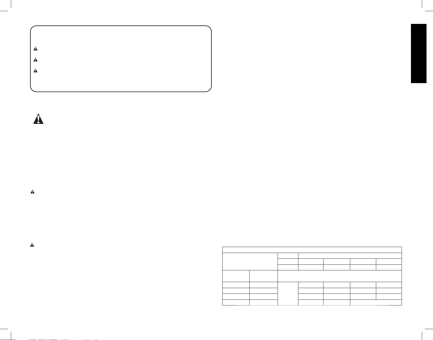
Definitions: Safety Guidelines
The definitions below describe the level of severity for each signal word. Please read
the manual and pay attention to these symbols.
DANGER: Indicates an imminently hazardous situation which, if not avoided, will
result in death or serious injury.
WARNING: Indicates a potentially hazardous situation which, if not avoided, could
result in death or serious injury.
CAUTION: Indicates a potentially hazardous situation which, if not avoided, may
result in minor or moderate injury.
NOTICE: Indicates a practice not related to personal injury which, if not avoided,
may result in property damage.
IF YOU HAVE ANY QUESTIONS OR COMMENTS ABOUT THIS OR ANY DEWALT
TOOL, CALL US TOLL FREE AT: 1-800-4-D
EWALT (1-800-433-9258)
IMPORTANT SAFETY INSTRUCTIONS
WARNING: Read all instructions before operating product. Failure to follow
all instructions listed below may result in electric shock, fi re and/or serious
injury.
READ ALL INSTRUCTIONS
Double Insulation
Double insulated tools are constructed throughout with two separate layers of electrical
insulation or one double thickness of insulation between you and the tool’s electrical
system. Tools built with this insulation system are not intended to be grounded. As a result,
your tool is equipped with a two prong plug which permits you to use extension cords
without concern for maintaining a ground connection.
NOTE: Double insulation does not take the place of normal safety precautions when
operating this tool. The insulation system is for added protection against injury resulting
from a possible electrical insulation failure within the tool.
CAUTION: WHEN SERVICING USE ONLY IDENTICAL REPLACEMENT PARTS.
Repair or replace damaged cords.
Polarized Plugs
Polarized plugs (one blade is wider than the other) are used on equipment to reduce the
risk of electric shock. When provided, this plug will fit in the polarized outlet only one way.
If the plug does not fit fully in the outlet, reverse the plug. If it still does not fit, contact a
qualified electrician to install the proper outlet. Do not change the plug in any way.
Safety Instructions For All Tools
This miter saw accepts the DEWALT worklight and laser attachments.
WARNING: To reduce the risk of eye injury, ALWAYS use eye protection when
operating the miter saw.
• KEEP GUARD IN PLACE and in working order.
• REMOVE ADJUSTING KEYS AND WRENCHES. Form habit of checking to see that
keys and adjusting wrenches are removed from spindle before turning tool on. Tools,
scrap pieces, and other debris can be thrown at high speed, causing injury.
• KEEP WORK AREA CLEAN. Cluttered areas and benches invite accidents.
• DO NOT USE THE MACHINE IN A DANGEROUS ENVIRONMENT. The use of power
tools in damp or wet locations or in rain can cause shock or electrocution. Keep your
work area well-lit to avoid tripping or placing arms, hands, and fingers in danger.
• KEEP CHILDREN AWAY. All visitors should be kept at a safe distance from work area.
Your shop is a potentially dangerous environment.
• MAKE WORKSHOP CHILDPROOF with padlocks, master switches, or by removing
starter keys. The unauthorized start-up of a machine by a child or visitor may result in
injury.
• DON’T FORCE TOOL. It will do the job better and be safer at the rate for which it was
designed.
• USE RIGHT TOOL. Don’t force tool or attachment to do a job for which it was not
designed. Using the incorrect tool or attachment may result in personal injury.
• WEAR PROPER APPAREL. No loose clothing, gloves, neckties, rings, bracelets, or
other jewelry to get caught in moving parts. Non-slip footwear is recommended. Wear
protective hair covering to contain long hair. Air vents may cover moving parts and
should also be avoided.
• ALWAYS USE SAFETY GLASSES. Everyday eyeglasses are NOT safety glasses.
Also use face or dust mask if cutting operation is dusty. ALWAYS WEAR CERTIFIED
SAFETY EQUIPMENT:
• ANSI Z87.1 eye protection (CAN/CSA Z94.3)
• ANSI S12.6 (S3.19) hearing protection
• NIOSH/OSHA/MSHA respiratory protection
• SECURE THE WORKPIECE. Use clamps or a vise to hold the workpiece on the table
and against the fence or when your hand will be dangerously close to the blade [within
6" (152 mm)]. It is safer than using your hand and it frees both hands to operate tool.
• DON’T OVERREACH. Keep proper footing and balance at all times. Loss of balance
may cause personal injury.
• MAINTAIN TOOLS WITH CARE. Keep tools sharp and clean for best and safest
performance. Follow instructions for lubricating and changing accessories. Poorly
maintained tools and machines can further damage the tool or machine and/or cause
injury.
• TURN THE MACHINE “OFF”, AND DISCONNECT THE MACHINE FROM THE
POWER SOURCE before installing or removing accessories, before adjusting or
changing set-ups, when making repairs or changing locations. An accidental start-up
can cause injury. Do not touch the plug’s metal prongs when unplugging or plugging in
the cord.
• REDUCE THE RISK OF UNINTENTIONAL STARTING. Make sure that the switch is
in the “OFF” position before plugging in the power cord.
• USE PROPER EXTENSION CORD. Make sure your extension cord is in good
condition. If your product is equipped with a cordset, use only 3-wire extension cords
that have 3-prong grounding-type plugs and 3-pole receptacles that accept the tool’s
plug. When using an extension cord, be sure to use one heavy enough to carry the
current your product will draw. An undersized cord will cause a drop in line voltage
resulting in loss of power and overheating. The following table shows the correct size
to use depending on cord length and nameplate ampere rating. If in doubt, use the next
heavier gague. The smaller the gauge number, the heavier the cord.
Minimum Gauge for Cord Sets
Volts Total Length of Cord in Feet (meters)
Ampere Rating
More
Than
0 6 18 16 16 14
610 18161412
10 12 16 16 14 12
12 16 14 12 Not Recommended
Not More
Than
120V
240V
25 (7.6) 50 (15.2) 100 (30.5) 150 (45.7)
50 (15.2) 100 (30.5) 200 (61.0) 300 (91.4)
AWG
English
1
Page 4

• CHECK for DAMAGED PARTS. Before further use of the tool, a guard or other part
that is damaged should be carefully checked to determine that it will operate properly
and perform its intended function—check for alignment of moving parts, binding of
moving parts, breakage of parts, mounting and any other conditions that may affect
its operation. A guard or other part that is damaged should be properly repaired or
replaced. Do not use tool if switch does not turn it on and off.
• USE RECOMMENDED ACCESSORIES. Use only accessories that are recommended
English
by the manufacturer for your model. Accessories that may be suitable for one tool
may be hazardous when used on another tool. Consult the instruction manual for
recommended accessories. The use of improper accessories may cause risk of injury
to persons.
• NEVER STAND ON TOOL. Serious injury could occur if the tool is tipped or if the
cutting tool is unintentionally contacted.
• NEVER LEAVE TOOL RUNNING UNATTENDED. TURN POWER OFF. Don’t leave
tool until it comes to a complete stop. Serious injury can result.
• DO NOT OPERATE ELECTRIC TOOLS NEAR FLAMMABLE LIQUIDS OR IN
GASEOUS OR EXPLOSIVE ATMOSPHERES. Motors in these tools may spark and
ignite fumes.
• STAY ALERT, WATCH WHAT YOU ARE DOING, AND USE COMMON SENSE. DO
NOT USE THE MACHINE WHEN YOU ARE TIRED OR UNDER THE INFLUENCE
OF DRUGS or ALCOHOL. A moment of inattention while operating power tools may
result in injury.
Additional Safety Rules For Miter Saws
WARNING: Do not allow familiarity (gained from frequent use of your saw) to replace
safety rules. Always remember that a careless fraction of a second is sufficient to inflict
severe injury.
• DO NOT OPERATE THIS MACHINE until it is completely assembled and installed
according to the instructions. A machine incorrectly assembled can cause serious
injury.
• OBTAIN ADVICE from your supervisor, instructor, or another qualified person if you
are not thoroughly familiar with the operation of this machine. Knowledge is safety.
• STABILITY. Make sure the miter saw is placed on a secure supporting surface and
does not slip or move during use. If the mobility kit is installed, raise the moveable
caster(s) so saw is in its stationary position.
• FOLLOW ALL WIRING CODES and recommended electrical connections to prevent
shock or electrocution. Protect electric supply line with at least a 15 ampere time-delay
fuse or a circuit breaker.”
• MAKE CERTAIN the blade rotates in the correct direction. The teeth on the blade
should point in the direction of rotation as marked on the saw.
• TIGHTEN ALL CLAMP HANDLES, knobs and levers prior to operation. Loose clamps
can cause parts or the workpiece to be thrown at high speeds.
• BE SURE all blade and blade clamps are clean, recessed sides of blade clamps are
against blade and arbor screw is tightened securely. Loose or improper blade clamping
may result in damage to the saw and possible personal injury.
• ALWAYS USE A SHARP BLADE. Check the blade to see if it runs true and is free
from vibration. A dull or a vibrating blade can cause damage to the machine and/or
serious injury.
• DO NOT OPERATE ON ANYTHING OTHER THAN THE DESIGNATED VOLTAGE
for the saw. Overheating, damage to the tool and personal injury may occur.
• DO NOT WEDGE ANYTHING AGAINST THE FAN to hold the motor shaft. Damage
to tool and possible personal injury may occur.
• DO NOT force cutting action. Stalling or partial stalling of motor can cause damage. To
the machine or blade and/or serious injury.
• ALLOW THE MOTOR TO COME TO FULL SPEED prior to starting cut. Starting the
cut too soon may cause damage to the machine or blade and/or serious injury.
• NEVER CUT FERROUS METALS (Those with any iron or steel content) or masonry.
Either of these can cause the carbide tips to fly off the blade at high speeds causing
serious injury.
• DO NOT USE ABRASIVE WHEELS. The excessive heat and abrasive particles
generated by them may damage the saw and cause personal injury.
• NEVER have any part of your body in line with the path of the saw blade. Personal
injury will occur.
• NEVER apply blade lubricant to a running blade. Applying lubricant could cause your
hand to move into the blade resulting in serious injury.
• DO NOT place either hand in the blade area when the saw is connected to the power
source. Inadvertent blade activation may result in serious injury.
• DO NOT PERFORM FREE-HAND OPERATIONS (workpiece not supported by table
and fence). Hold the work firmly against the fence and table. Free-hand operations on
a miter saw could cause the workpiece to be thrown at high speeds, causing serious
injury.
• NEVER REACH AROUND or behind the saw blade. A blade can cause serious
injury.
• DO NOT reach underneath the saw unless it is unplugged and turned off. Contact with
saw blade may cause personal injury.
• SECURE THE MACHINE TO A STABLE SUPPORTING SURFACE. Vibration can
possibly cause the machine to slide, walk, or tip over, causing serious injury.
• USE ONLY CROSSCUT SAW BLADES recommended for miter saws. For best
results, do not use carbide tipped blades with hook angles in excess of 7 degrees. Do
not use blades with deep gullets. These can deflect and contact the guard, and can
cause damage to the machine and/or serious injury.
• USE ONLY BLADES OF THE CORRECT SIZE AND TYPE specified for this tool to
prevent damage to the machine and/or serious injury.
• INSPECT BLADE FOR CRACKS or other damage prior to operation. A cracked or
damaged blade can come apart and pieces can be thrown at high speeds, causing
serious injury. Replace cracked or damaged blades immediately.
• CLEAN THE BLADE AND BLADE CLAMPS prior to operation. Cleaning the blade
and blade clamps allows you to check for any damage to the blade or blade clamps. A
cracked or damaged blade or blade clamp can come apart and pieces can be thrown
at high speeds, causing serious injury.
• DO NOT use lubricants or cleaners (particularly spray or aerosol) in the vicinity of the
plastic guard. The polycarbonate material used in the guard is subject to attack by
certain chemicals.
• ALWAYS USE THE KERF PLATE AND REPLACE THIS PLATE WHEN DAMAGED.
Small chip accumulation under the saw may interfere with the saw blade or may cause
instability of workpiece when cutting.
• USE ONLY BLADE CLAMPS specified for this tool to prevent damage to the machine
and/or serious injury.
• CLEAN THE MOTOR AIR SLOTS of chips and sawdust. Clogged motor air slots can
cause the machine to overheat, damaging the machine and possibly causing a short
which could cause serious injury.
• KEEP ARMS, HANDS, AND FINGERS away from the blade to prevent severe cuts.
Clamp all workpieces that would cause your hand to be within 6" (152 mm) of the saw
blade.
• NEVER LOCK THE SWITCH IN THE “ON” position. Severe personal injury may
result.
2
Page 5
• TURN OFF THE MACHINE and allow the blade to come to a complete stop before
raising the arm and prior to cleaning the blade area, removing debris in the path of the
blade, before servicing or adjusting tool. A moving blade can cause serious injury.
• PROPERLY SUPPORT LONG OR WIDE WORKPIECES. Loss of control of the
workpiece can cause injury.
• NEVER cross arms in front of blade while using tool. Always make a dry run
(unpowered) before making a finish cut so that you can check the path of the blade or
severe personal injury may result.
• ADDITIONAL INFORMATION regarding the safe and proper operation of power
tools (i.e. a safety video) is available from the Power Tool Institute, 1300 Sumner
Avenue, Cleveland, OH 44115-2851 (www.powertoolinstitute.com). Information is also
available from the National Safety Council, 1121 Spring Lake Drive, Itasca, IL 60143-
3201. Please refer to the American National Standards Institute ANSI 01.1 Safety
Requirements for Woodworking Machines and the U.S. Department of Labor OSHA
1910.213 Regulations.
WARNING: Do not connect unit to electrical power source until complete instructions
are read and understood.
WARNING: Always wear proper personal hearing protection that conforms to
ANSI S12.6 (S3.19) during use. Under some conditions and duration of use, noise from
this product may contribute to hearing loss.
WARNING: NEVER MAKE ANY CUT UNLESS THE MATERIAL IS SECURED ON
THE TABLE AND AGAINST THE FENCE.
WARNING: Some dust created by power sanding, sawing, grinding, drilling, and other
construction activities contains chemicals known to cause cancer, birth defects or other
reproductive harm. Some examples of these chemicals are:
• lead from lead-based paints,
• crystalline silica from bricks and cement and other masonry products, and
• arsenic and chromium from chemically-treated lumber (CCA).
Your risk from these exposures varies, depending on how often you do this type of work.
To reduce your exposure to these chemicals: work in a well ventilated area, and work
with approved safety equipment, such as those dust masks that are specially designed to
filter out microscopic particles.
• Avoid prolonged contact with dust from power sanding, sawing, grinding,
drilling, and other construction activities. Wear protective clothing and wash
exposed areas with soap and water. Allowing dust to get into your mouth, eyes, or
lay on the skin may promote absorption of harmful chemicals.
WARNING: Use of this tool can generate and/or disburse dust, which may cause serious
and permanent respiratory or other injury. Always use NIOSH/OSHA approved respiratory
protection appropriate for the dust exposure. Direct particles away from face and body.
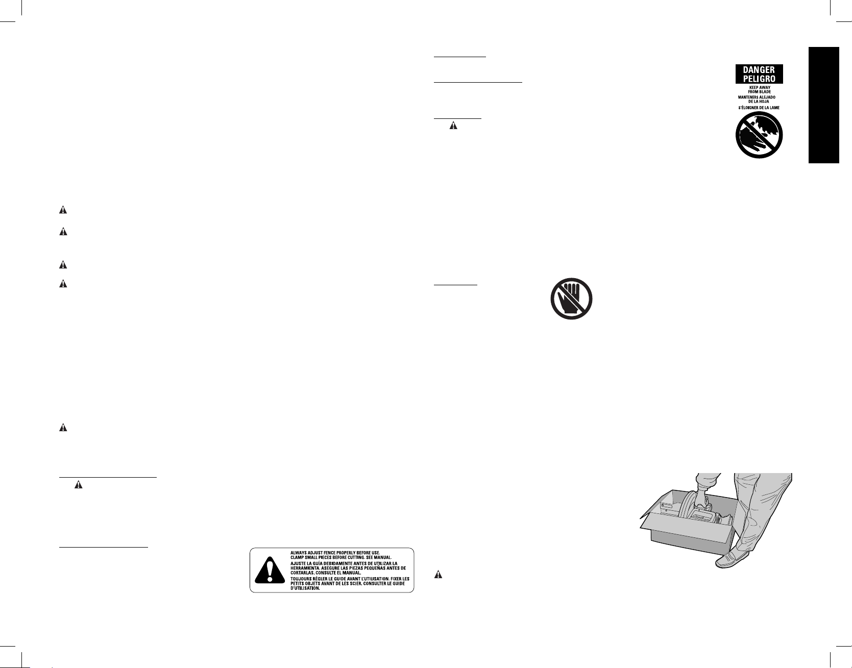
For your convenience and safety, the following warning labels are on your miter saw.
ON MOTOR HOUSING:
WARNING: FOR YOUR OWN SAFETY, READ INSTRUCTION MANUAL
BEFORE OPERATING SAW.
WHEN SERVICING, USE ONLY IDENTICAL RE PLACE MENT PARTS.
ALWAYS WEAR EYE PROTECTION.
DO NOT EXPOSE TO RAIN OR USE IN DAMP LOCATIONS.
ON MOVING FENCE:
ALWAYS ADJUST FENCE PROPERLY
BEFORE USE. CLAMP SMALL PIECES
BEFORE CUTTING. SEE MANUAL.
ON GUARD:
DANGER – KEEP AWAY FROM BLADE.
ON UPPER GUARD:
PROPERLY SECURE BRACKET WITH BOTH SCREWS BEFORE
USE.
ON TABLE: (2 PLACES)
WARNING: FOR YOUR OWN SAFETY READ INSTRUCTION
MANUAL BEFORE OPERATING MITER SAW.
KEEP HANDS OUT OF PATH OF SAW BLADE.
DO NOT OPERATE SAW WITHOUT GUARDS IN PLACE.
CHECK LOWER GUARD FOR PROPER CLOSING BEFORE EACH USE.
ALWAYS TIGHTEN ADJUSTMENT BEFORE USE. DO NOT PERFORM ANY
OPERATION FREEHAND.
NEVER REACH IN BACK OF SAW BLADE. NEVER CROSS ARMS IN FRONT
OF BLADE. TURN OFF TOOL AND WAIT FOR SAW BLADE TO STOP BEFORE
MOVING WORKPIECE, CHANGING SETTINGS OR MOVING HANDS.
DISCONNECT POWER BEFORE CHANGING BLADE OR SERVICING.
TO REDUCE THE RISK OF INJURY, ALLOW SAW TO RETURN TO THE
FULL UP POSITION AFTER EACH OPERATION. THINK! YOU CAN PREVENT
ACCIDENTS.
ON BASE: (2 PLACES)
Electrical Connection
Be sure your power supply agrees with the nameplate marking. 120 volts, AC means that
your saw will operate on alternating current only. A voltage decrease of 10 percent or more
will cause a loss of power and overheating. All D
does not operate, check the power supply.
EWALT tools are factory tested. If this tool
Unpacking Your Saw
Check the contents of your miter saw carton to make sure that you have received all parts.
In addition to this instruction manual, the carton should contain:
1. One No. DW713 miter saw with blade.
2. One blade wrench in wrench pocket shown in Figure 2.
3. One No. DW7053 Dust Bag.
Familiarization
Your miter saw is fully assembled in the carton.
Open the box and lift the saw out by the
convenient carrying handle, as shown in Figure
1.
Place the saw on a smooth, flat surface such as
a workbench or strong table.
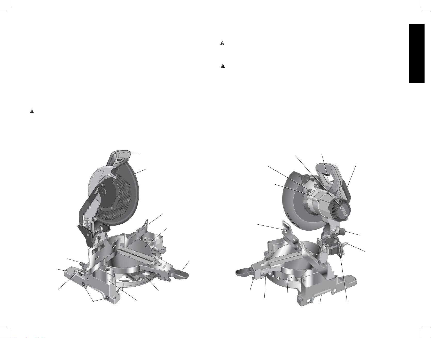
Examine Figures 2 and 3 to become familiar
with the saw and its various parts. The section
on adjustments will refer to these terms and you
must know what and where the parts are.
CAUTION: Pinch Hazard. To reduce the risk of
injury, keep thumb underneath the handle when pulling the handle down. The lower guard
will move up as the handle is pulled down which could cause pinching.The handle is placed
close to the guard for special cuts.
FIG. 1
English
3
Page 6
Press down lightly on the operating handle and pull out the lock down pin, as shown in
Figure 4. Gently release the downward pressure and allow the arm to rise to its full height.
Use the lock down pin when carrying the saw from one place to another. Always use the
carrying handle to transport the saw or the hand indentations shown in Figure 3.
Specifications
CAPACITY OF CUT
50° miter left and right
English
48° bevel left: 3° right
0° miter
Max. Height 3.5" (89 mm) Result Width 3.5" (89 mm)
Max. Width 6.1" (155 mm) Result Height 1.25" (32 mm)
45° miter
Max. Height 3.5" (89 mm) Result Width 2.4" (61 mm)
Max. Width 4.2" (107 mm) Result Height 1.25" (32 mm)
45° bevel
Max. Height 2.3" (58 mm) Result Width 3.5" (89 mm)
Max. Width 6.1" (155 mm) Result Height .75" (19 mm)
31.62° miter and 33.85° bevel
Max. Width 5.25" (133 mm) Result Height .9" (23 mm)
DRIVE
120 Volt Motor
2200 Watts 15 Amp Motor
5000 RPM Cut Helical Gears with Roller and Ball Bearings
Carbide Tooth Blade Automatic Electric Brake
Optional Accessories
The following accessories, designed for your saw, may be helpful. In some cases, other
locally obtained work supports, length stops, clamps, etc., may be more appropriate. Use
care in selecting and using accessories.
Extension, Work Support: DW7080
Used to support long overhanging workpieces, the work support is user assembled.
Your saw table is designed to accept two work supports; one on each side.
Adjustable Length Stop: DW7051
Requires the use of one work support (see drawing). It is used to make repetitive cuts
of the same length from 0 to 42" (107 cm).
Clamp: DW7082
Used for firmly clamping workpiece to the saw fence for precision cutting.
Dust Bag: DW7053 (Included with some models)
Equipped with a zipper for easy emptying, the dust bag will capture the majority of the
sawdust produced (not shown).
Crown Molding Fence: DW7084
Used for precision cutting of crown molding.
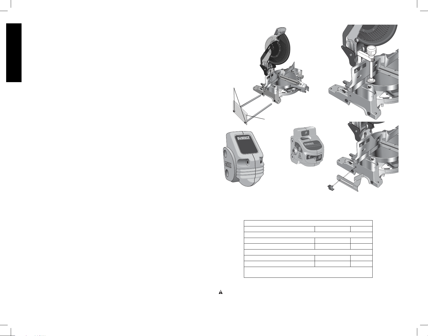
Laser Guide System: DW7187
Powered by the saw, the bright laser line delivers enhanced visibility in low and high
light locations. Easy to install.
Miter Saw LED Worklight System: DWS7085
Lighting used for greater visibility and cutting alignment during operation. Easy to
install.
Miter Saw Replacement Kerf Plate: DW7055
This durable plastic uncut plate limits blade tear out.
DW7080
LOCKNUTS
END PLATE
DW7187
DWS7085
SAW BLADES: ALWAYS USE 10" (254 mm) SAW BLADES WITH 5/8" (16 mm) ARBOR
HOLES. SPEED RATING MUST BE AT LEAST 5500 RPM. Never use a smaller diameter
blade. It will not be guarded properly. Use crosscut blades only! Do not use blades
designed for ripping, combination blades or blades with hook angles in excess of 7˚.
BLADE DESCRIPTIONS
APPLICATION DIAMETER TEETH
Construction Saw Blades (thin kerf with anti-stick rim)
General Purpose 10" (254 mm) 40
Fine Crosscuts 10" (254 mm) 60
Woodworking Saw Blades (provide smooth, clean cuts)
Fine crosscuts 10" (254 mm) 80
Non-ferrous metals 10" (254 mm) 80
NOTE: For cutting non-ferrous metals, use only saw blades
with TCG teeth designed for this purpose.
DW7082
DW7084
ACCESSORIES
WARNING: Since accessories, other than those offered by DEWALT, have not been
tested with this product, use of such accessories with this tool could be hazardous. To
reduce the risk of injury, only D
this product.
EWALT, recommended accessories should be used with
4
Page 7
Recommended accessories for use with your tool are available for purchase from your local
dealer or authorized service center. If you need assistance in locating any accessory for
your tool, please contact D
MD 21286, call 1-800-4-D
EWALT Industrial Tool Co., 701 East Joppa Road, Baltimore,
EWALT (1-800-433-9258) or visit our website www.dewalt.com.
Bench Mounting
Holes are provided in all four feet to facilitate bench mounting, as shown in Figure 2. (Two
different sized holes are provided to accommodate different sizes of screws. Use either
hole, it is not necessary to use both.) Always mount your saw firmly to prevent movement.
To enhance the tool’s portability, it can be mounted to a piece of 1/2" (12.7 mm) or thicker
plywood which can then be clamped to your work support or moved to other job sites and
reclamped.
NOTE: If you elect to mount your saw to a piece of plywood, make sure that the mounting
screws don’t protrude from the bottom of the wood. The plywood must sit flush on the
work support. When clamping the saw to any work surface, clamp only on the clamping
bosses where the mounting screw holes are located. Clamping at any other point will surely
interfere with the proper operation of the saw.
CAUTION: To prevent binding and inaccuracy, be sure the mounting surface is not
warped or otherwise uneven. If the saw rocks on the surface place a thin piece of material
under one saw foot until the saw sits firmly on the mounting surface.
IMPORTANT SAFETY INSTRUCTIONS
Changing or Installing a New Saw Blade (Fig. 5, 6)
WARNING: To reduce the risk of serious personal injury, turn off the tool
and disconnect it from the power source before attempting to move it, change
accessories or make any adjustments accept as written in laser adjustment
instructions.
CAUTION:
• Never depress the spindle lock button while the blade is under power or coasting.
• Do not cut ferrous metal (containing iron or steel) or masonry or fiber cement product
with this miter saw.
Removing the Blade
1. Unplug the saw.
2. Raise the arm to the upper position and raise the lower guard as far as possible.
3. Loosen, but do not remove guard bracket screw until the bracket can be raised far
enough to access the blade screw. Lower guard will remain raised due to the position
of the guard bracket screw.
4. Depress the spindle lock button (Fig. 3) while carefully rotating the saw blade by hand
until the lock engages.
English
FIG. 2
LEFT SIDE FENCE
CLAMPING KNOB
BENCH
MOUNTING
HOLES
WRENCH
HOLES FOR
EXTENSION KIT
OPERATING
HANDLE
GUARD
RIGHT SIDE
MITER SCALE
BASE
FENCE
TABLE
MITER LOCK
LEVER
FIG. 3
SPINDLE LOCK
BUTTON
MOTOR
HOUSING
LEFT SIDE
FENCE
MITER
DETENT
5
MITER
DETENT
OVER RIDE
MOTOR
END CAP
MITER
SCALE
TRIGGER
SWITCH
HAND
INDENTATION
CARRYING
HANDLE
DUST
SPOUT
BEVEL CLAMP
KNOB
BEVEL
SCALE
Page 8
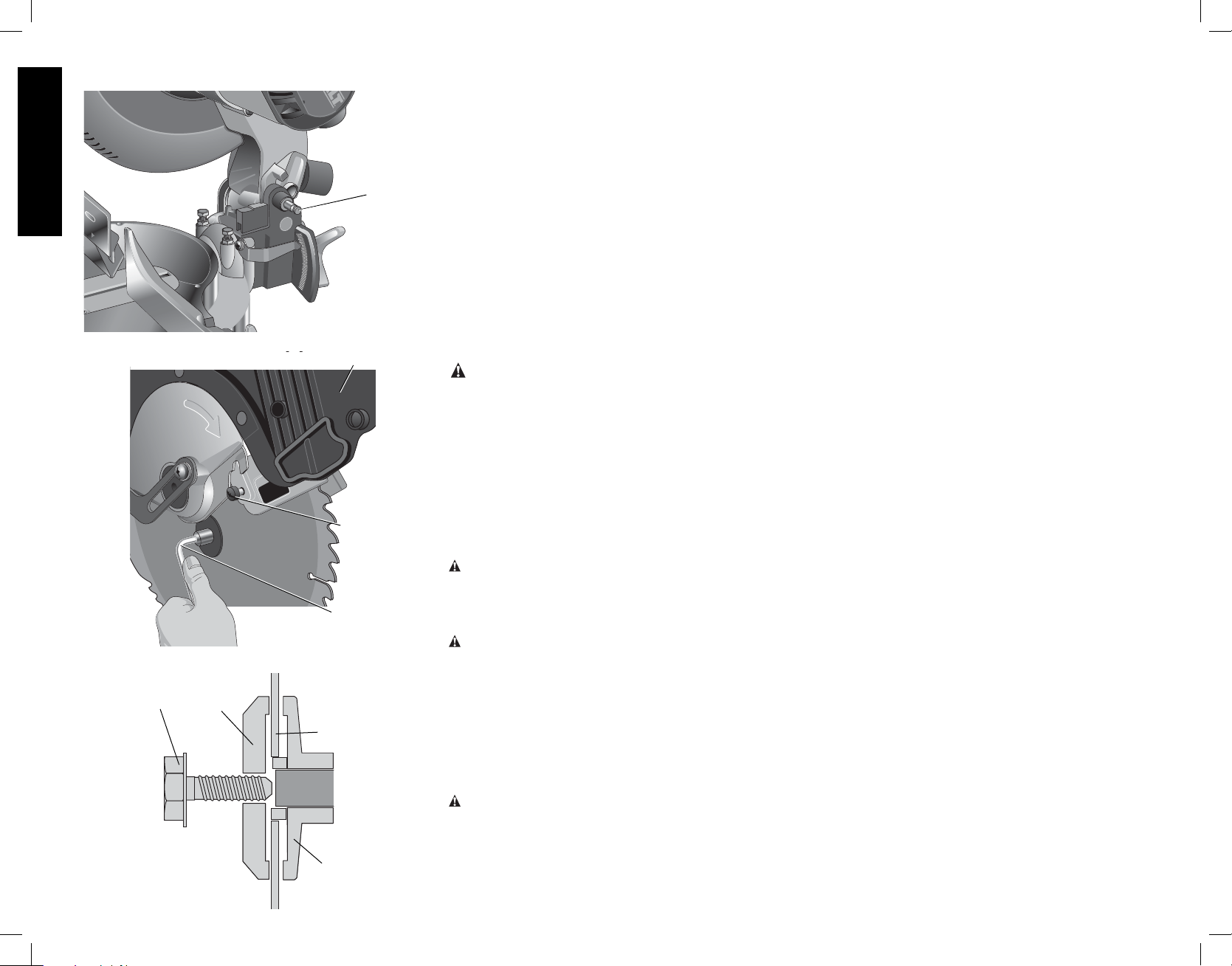
FIG. 4
English
FIG. 5
FIG. 6
BLADE
SCREW
OUTER
CLAMP
WASHER
LOCK
DOWN
PIN
GUARD
GUARD
BRACKET
SCREW
WRENCH
BLADE
INNER CLAMP
WASHER
5. Keeping the button depressed, use the other hand and
the wrench provided to loosen the blade screw. (Turn
clockwise, left-hand threads.)
6. Remove the blade screw, outer blade clamp, and
blade. The inner blade clamp may be left on the
spindle.
Installing a Blade
1. Unplug the saw.
2. With the arm raised, the lower guard held open and the
guard bracket, place the blade on the spindle against
the inner blade clamp with the teeth at the bottom of
the blade pointing toward the back of the saw.
3. Assemble the outer blade clamp onto the spindle.
4. Install the blade screw and, engaging the spindle lock,
tighten the screw firmly with wrench provided. (Turn
counterclockwise, left-hand threads.)
5. Return the guard bracket to its original position and
firmly tighten the guard bracket screw to hold bracket
in place.
WARNING:
• The guard bracket must be returned
to its original position and the
screw tightened before activating
the saw.
• Failure to do so may allow the guard
to contact the spinning saw blade
resulting in damage to the saw and
severe personal injury.
Transporting the Saw
WARNING: To reduce the risk of serious personal
injury, turn off the tool and disconnect it from the
power source before attempting to move it, change
accessories or make any adjustments accept as
written in laser adjustment instructions.
WARNING: To reduce the risk of serious personal
injury, ALWAYS lock the miter lock handle, bevel lock
handle, down lock pin, and fence adjustment knob before
transporting saw.
In order to conveniently carry the miter saw from place to
place, a carrying handle has been included on the top of
the saw arm, as shown in Figure 3. To transport the saw,
lower the arm and depress the lock down pin shown in
Figure 4.
ADJUSTMENTS
WARNING: To reduce the risk of serious personal
injury, turn off the tool and disconnect it from the
power source before attempting to move it, change
accessories or make any adjustments accept as
written in laser adjustment instructions.
NOTE: Your miter saw is fully and accurately adjusted at
the factory at the time of manufacture. If readjustment due
to shipping and handling or any other reason is required,
follow the steps below to adjust your saw.
Once made, these adjustments should remain accurate.
Take a little time now to follow these directions carefully to
maintain the accuracy of which your saw is capable.
MITER SCALE ADJUSTMENT
Place a square against the saw’s fence and blade, as
shown in Figure 7. (Do not touch the tips of the blade
teeth with the square. To do so will cause an inaccurate
measurement.) Unlock miter lock lever (see Fig. 8) and
swing the miter arm until the miter detent locks it at the 0˚
miter position. Do not lock miter lock lever. If the saw blade
is not exactly perpendicular to the fence, loosen the three
screws that hold the miter scale to the base (shown in
Fig. 8) and move the scale/miter arm assembly left or right
until the blade is perpendicular to the fence, as measured
with the square. Retighten the three screws. Pay no
attention to the reading of the miter pointer at this point.
MITER POINTER ADJUSTMENT
Unlock miter lock lever and squeeze the miter detent
to move the miter arm to the zero position, as shown in
Figure 8. Unlock the miter lock lever to allow the miter
detent to snap into place as you rotate the miter arm past
zero. Observe the pointer and miter scale through the
viewing opening shown in Figure 9. If the pointer does not
indicate exactly zero, loosen the pointer screw, adjust the
pointer to 0˚ and retighten.
BEVEL SQUARE TO TABLE
To align the blade square to the rotary table, lock the arm
in the down position. Place a square against the blade
taking care to not have the square on top of a tooth, as
shown in Figure 10B. Loosen the Bevel Clamp Knob so
that you can move the Bevel Arm. Move the Bevel Arm
as necessary so that the blade is at 0° bevel to the table.
If the Bevel Arm needs adjustment, loosen the lock nut on
the right side Bevel Stop as shown in Figure 11, and adjust
the stop screw as necessary. Hold the stop screw in place
and tighten the lock nut.
BEVEL POINTER
If the bevel pointer does not indicate zero, loosen the screw
that holds it in place and move the pointer as necessary.
Suggestion: For accuracy, set the top edge so that it
aligns with zero.
BEVEL STOP
To set the 45° bevel stop shown in Figure 12, first loosen
the left side fence clamping knob and slide the left side
fence as far as it will go to the left. Move the arm to the
left until it stops on the left bevel stop screw. If the bevel
pointer does not indicate exactly 45°, loosen the left side
bevel stop lock nut and turn the screw downwards. Move
the arm to the left and tighten the bevel clamp knob firmly
6
Page 9
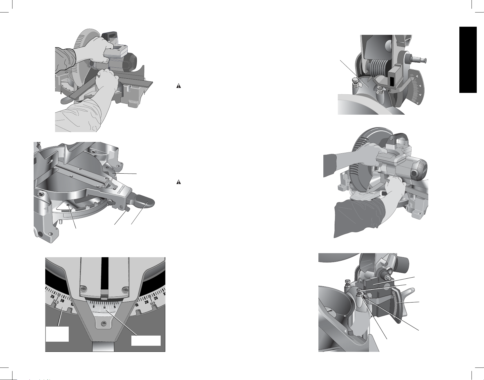
FIG. 7
FIG. 8
FIG.9
ADJUSTMENT
(three of these)
MITER
SCALE
SCREW
MITER
DETENT
MITER
LOCK
LEVER
POINTER
MITER
SCALE
when the bevel pointer indicates exactly 45°. Adjust the
left side bevel stop screw upwards until it firmly touches
the bevel stop. Retighten the nut while holding the screw
from turning.
To achieve 3° right bevel or 48° left bevel, the stop screws
must be adjusted to allow the arm to move to the desired
location. The bevel stops will need readjustment to the
zero and 45° positions after cuts are made.
FENCE ADJUSTMENT
WARNING: To reduce the risk of serious personal
injury, turn off the tool and disconnect it from the
power source before attempting to move it, change
accessories or make any adjustments accept as
written in laser adjustment instructions.
To bevel UP TO 48° left, the left side of the fence can
be adjusted to the left to provide clearance. To adjust
the fence, loosen the knob shown in Figure 13 and slide
the fence to the left. Make a dry run with the saw turned
off and check for clearance. Adjust the fence to be as
close to the blade as practical to provide maximum
workpiece support, without interfering with arm up and
down movement. Tighten knob securely. When the bevel
operations are complete, don’t forget to relocate the fence
to the right.
GUARD ACTUATION AND VISIBILITY
CAUTION: Pinch Hazard. To reduce the risk of injury,
keep thumb underneath the handle when pulling the
handle down. The lower guard will move up as the handle
is pulled down which could cause pinching.
The blade guard on your saw has been designed to
automatically raise when the arm is brought down and to
lower over the blade when the arm is raised.
The guard can be raised by hand when installing or
removing saw blades or for inspection of the saw. NEVER
RAISE THE BLADE GUARD MANUALLY UNLESS THE
SAW IS TURNED OFF.
NOTE: Certain special cuts will require that you manually
raise the guard. See section on Cutting Base Molding
Up to 3.5" (88.9 mm) High (page 11).
The front section of the guard is louvered for visibility
while cutting. Although the louvers dramatically reduce
flying debris, they are openings in the guard and safety
glasses should be worn at all times when viewing through
the louvers.
AUTOMATIC ELECTRIC BRAKE
Your saw is equipped with an automatic electric blade
brake which stops the saw blade within 5 seconds of
trigger release. This is not adjustable.
On occasion, there may be a delay after trigger release to
brake engagement. On rare occasions, the brake may not
engage at all and the blade will coast to a stop.
If a delay or “skipping” occurs, turn the saw on and off 4 or
5 times. If the condition persists, have the tool serviced by
an authorized D
EWALT service center.
7
FIG. 10A
BEVEL
HOUSING
FIG. 10B
FIG. 11
LOCK NUT
English
BEVEL STOP
STOP SCREW
BEVEL
SCALE
BEVEL
POINTER
SCREW
Page 10
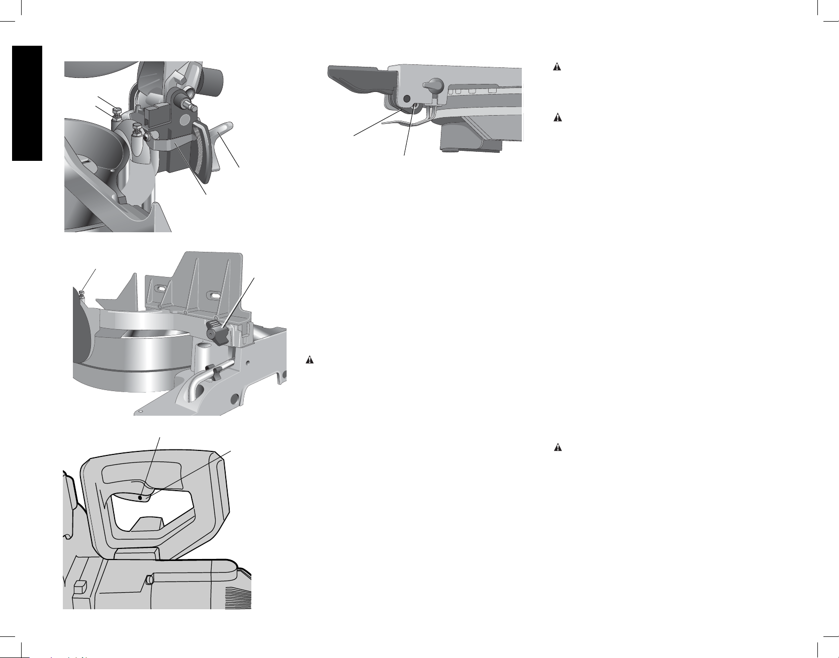
FIG. 12
STOP
SCREW
LOCK
NUT
English
FIG. 13
FIG. 14
LEFT SIDE
BEVEL STOP
SCREW
HOLE FOR PADLOCK
BEVEL
POINTER
BEVEL
CLAMP
KNOB
LEFT SIDE
FENCE
CLAMPING
KNOB
TRIGGER
SWITCH
FIG. 15
SLOTTED
ADJUSTMENT
ROD
SET SCREW (IF EQUIPPED)
Always be sure the blade has stopped before removing it
from the kerf. The brake is not a substitute for guards or for
ensuring your own safety by giving the saw your complete
attention.
MITER LOCK ADJUSTMENT (FIG. 15)
The miter lock rod should be adjusted if the table of the
saw can be moved when the miter lock handle is locked
down. To adjust, put the miter lock handle in the up
position. Using a slotted screwdriver, adjust the lock rod in
1/8 clockwise turn increments to increase the lock force.
To ensure the miter lock is functioning properly, re-lock
miter lock handle to a non-detent miter angle.
NOTE: Some models may have a set screw as shown in
Figure 15. Using a 3/32 hex wrench, loosen the set screw
on the pivot pin. Tighten set screw after adjustment is
complete.
Brushes
WARNING: To reduce the risk of serious personal
injury, turn off the tool and disconnect it from the
power source before attempting to move it, change
accessories or make any adjustments accept as
written in laser adjustment instructions.
Inspect carbon brushes regularly by unplugging tool,
removing the motor end cap (Fig. 2), lift the brush spring
and withdraw the brush assembly. Keep brushes clean
and sliding freely in their guides. Always replace a used
brush in the same orientation in the holder as it was prior
to its removal. Carbon brushes have varying symbols
stamped into their sides, and if the brush is worn down to
approximately 1/2" (12.7 mm), the spring will no longer exert
pressure and they must be replaced. Use only identical
EWALT brushes. Use of the correct grade of brush is
D
essential for proper operation of electric brake. New brush
assemblies are available at D
tool should be allowed to “run in” (run at no load) for 10
minutes before use to seat new brushes. The electric brake
may be erratic in operation until the brushes are properly
seated (worn in). Always replace the brush inspection cap
after inspection or servicing the brushes.
While “running in” DO NOT TIE, TAPE, OR OTHER WISE
LOCK THE TRIGGER SWITCH ON. HOLD BY HAND
ONLY.
EWALT service centers. The
OPERATION
WARNING: To reduce the risk of serious personal
injury, turn off the tool and disconnect it from the
power source before attempting to move it, change
accessories or make any adjustments accept as
written in laser adjustment instructions.
WARNING: Always use eye protection. All users and
bystanders must wear eye protection that conforms to
ANSI Z87.1 (CAN/CSA Z94.3).
Plug the saw into any household 60 Hz power source.
Refer to the nameplate for voltage. Be sure the cord will
not interfere with your work.
SWITCH
To turn the saw on, depress the trigger switch shown in
Figure 14. To turn the tool off, release the switch. There
is no provision for locking the switch on, but a hole is
provided in the trigger for insertion of a padlock to lock
the saw off.
CUTTING WITH YOUR SAW
NOTE: Although this saw will cut wood and many non-
ferrous materials, we will limit our discussion to the cutting
of wood only. The same guidelines apply to the other
materials. DO NOT CUT FERROUS (IRON AND STEEL)
MATERIALS OR MASONRY WITH THIS SAW. Do not
use any abrasive blades.
CROSSCUTS
Cutting of multiple pieces is not recommended but can
be done safely by ensuring that each piece is held firmly
against the table and fence. A crosscut is made by cutting
wood across the grain at any angle. A straight crosscut
is made with the miter arm at the zero degree position.
Set the miter arm at zero, hold the wood on the table and
firmly against the fence. Turn on the saw by squeezing the
trigger switch shown in Figure 14.
When the saw comes up to speed (about 1 second) lower
the arm smoothly and slowly to cut through the wood. Let
the blade come to a full stop before raising arm.
CAUTION: Always use a work clamp to maintain
control and reduce the risk of workpiece damage and
personal injury.
Miter crosscuts are made with the miter arm at some angle
other than zero. This angle is often 45° for making corners,
but can be set anywhere from zero to 50° left or right. After
selecting the desired miter angle, be sure to tighten the
miter lock lever. Make the cut as described above.
To cut through an existing pencil line on a piece of wood,
match the angle as close as possible. Cut the wood a little
too long and measure from the pencil line to the cut edge
to determine which direction to adjust the miter angle and
recut. This will take some practice, but it is a commonly
used technique.
8
Page 11
BEVEL CUTS
A bevel cut is a crosscut made with the saw blade at a
bevel to the wood. In order to set the bevel, loosen the
bevel clamp knob and move the saw to the left as desired.
(It is necessary to move the left side of the fence to
allow clearance). Once the desired bevel angle has been
set, tighten the bevel clamp knob firmly.
Bevel angles can be set from 3° right to 48° left and can
be cut with the miter arm set between zero and 50° right or
left. Ensure the fence has been adjusted properly. When
cutting left bevel, or right miter compound cuts, it will be
necessary to remove the adjustable fence.
QUALITY OF CUT
The smoothness of any cut depends on a number of
variables. Things like material being cut, blade type, blade
sharpness and rate of cut all contribute to the quality of
the cut.
When smoothest cuts are desired for molding and other
precision work, a sharp (60–80 tooth carbide) blade and a
slower, even cutting rate will produce the desired results.
Ensure that material does not creep while cutting. Clamp it
securely in place. Always let the blade come to a full stop
before raising arm.
If small fibers of wood still split out at the rear of the
workpiece, apply a piece of masking tape on the wood
where the cut will be made. Saw through the tape and
carefully remove tape when the cut is finished.
For varied cutting applications, refer to the list of
recommended saw blades for your saw and select the
one that best fits your needs (Page 4).
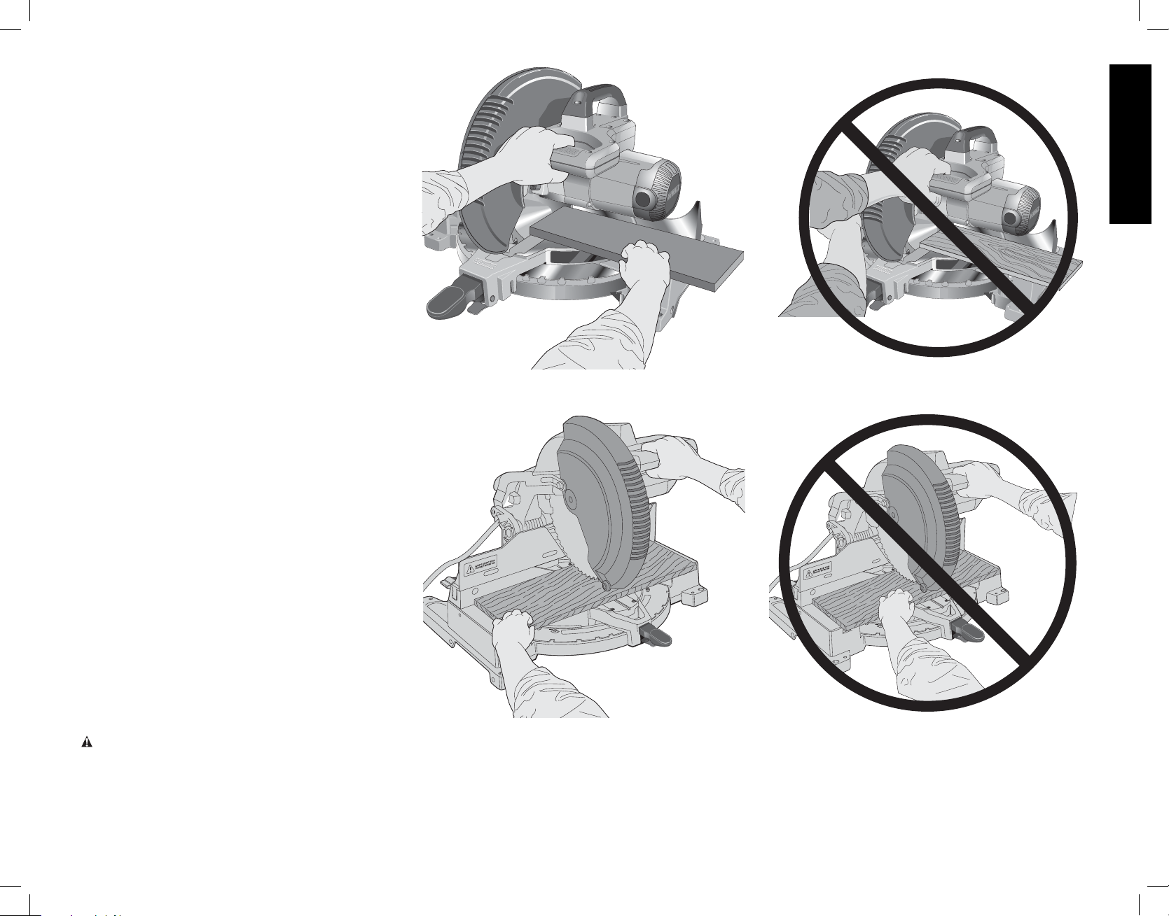
BODY AND HAND POSITION (FIG. 16)
Proper positioning of your body and hands when operating
the miter saw will make cutting easier, more accurate and
safer. Never place hands near cutting area. Place hands
no closer than 6" (152 mm) from the blade. Hold the
workpiece tightly to the table and the fence when cutting.
Keep hands in position until the trigger has been released
and the blade has completely stopped. ALWAYS MAKE
DRY RUNS (UNPOWERED) BEFORE FINISH CUTS SO
THAT YOU CAN CHECK THE PATH OF THE BLADE.
DO NOT CROSS HANDS, AS SHOWN IN FIGURE 15A.
Keep both feet firmly on the floor and maintain proper
balance. As you move the miter arm left and right, follow
it and stand slightly to the side of the saw blade. Sight
through the guard louvers when following a pencil line.
CLAMPING THE WORKPIECE
WARNING: To reduce the risk of serious personal
injury, turn off the tool and disconnect it from the
power source before attempting to move it, change
accessories or make any adjustments accept as
written in laser adjustment instructions.
FIG. 16
PROPER HAND POSITION
FIG. 16A
English
IMPROPER HAND POSITION
IMPROPER HAND POSITIONPROPER HAND POSITION
9
Page 12
WARNING: A workpiece that is clamped, balanced
and secure before a cut may become unbalanced after
a cut is completed. An unbalanced load may tip the
saw or anything the saw is attached to, such as a table
or workbench. When making a cut that may become
unbalanced, properly support the workpiece and ensure
the saw is firmly bolted to a stable surface. Personal injury
may occur.
English
WARNING: The clamp foot must remain clamped above
the base of the saw whenever the clamp is used. Always
clamp the workpiece to the base of the saw–not to any
other part of the work area. Ensure the clamp foot is not
clamped on the edge of the base of the saw.
CAUTION: Always use a work clamp to maintain
control and reduce the risk of workpiece damage and
personal injury.
If you cannot secure the workpiece on the table and
against the fence by hand, (irregular shape, etc.) or your
hand would be less than 6" (152 mm) from the blade, a
clamp or other fixture should be used.
For best results use the DW7082 clamp made for use
with your saw. It is available through your local retailer or
EWALT service center at extra cost.
D
Other aids such as spring clamps, bar clamps or C-clamps
may be appropriate for certain sizes and shapes of
material. Use care in selecting and placing these clamps.
Take time to make a dry run before making the cut. The
left fence will slide from side to side to aid in clamping.
TO INSTALL CLAMP (SOLD SEPARATELY)
1. Insert it into the hole behind the fence. The clamp
should be facing toward the back of the miter saw.
The groove on the clamp rod should be fully inserted
into the base. Ensure this groove is fully inserted into
the base of the miter saw. If the groove is visible, the
clamp will not be secure.
2. Rotate the clamp 180º toward the front of the miter
saw.
3. Loosen the knob to adjust the clamp up or down,
then use the fine adjust knob to firmly clamp the
workpiece.
NOTE: Place the clamp on the opposite side of the
base when beveling. ALWAYS MAKE DRY RUNS
(UNPOWERED) BEFORE FINISH CUTS TO CHECK
THE PATH OF THE BLADE. ENSURE THE CLAMP
DOES NOT INTERFERE WITH THE ACTION OF THE
SAW OR GUARDS.
WARNING: A workpiece that is clamped, balanced
and secure before a cut may become unbalanced after
a cut is completed. An unbalanced load may tip the
saw or anything the saw is attached to, such as a table
or workbench. When making a cut that may become
unbalanced, properly support the workpiece and ensure
the saw is firmly bolted to a stable surface.
FIG. 17
FIG. 20
FIG. 21
A.
FIG. 19
MITER
SCALE
FIG. 18
WARNING: The clamp foot must remain clamped
above the base of the saw whenever the clamp is used.
Always clamp the workpiece to the base of the saw–not to
any other part of the work area. Ensure the clamp foot is
not clamped on the edge of the base of the saw.
SUPPORT FOR LONG PIECES
B.
WARNING: To reduce the risk of serious personal
injury, turn off the tool and disconnect it from the
power source before attempting to move it, change
accessories or make any adjustments accept as
written in laser adjustment instructions.
ALWAYS SUPPORT LONG PIECES.
Never use another person as a substitute for a table
extension; as additional support for a workpiece that is
ANGLE “A”
longer or wider than the basic miter saw table or to help
feed, support or pull the workpiece.
For best results, use the DW7080 extension work support
to extend the table width of your saw. Available from your
dealer at extra cost.
Support long workpieces using any convenient means
such as sawhorses or similar devices to keep the ends
from dropping.
CUTTING PICTURE FRAMES, SHADOW BOXES AND
OTHER FOUR-SIDED PROJECTS
To best understand how to make the items listed here,
we suggest that you try a few simple projects using scrap
wood until you develop a “FEEL” for your saw.
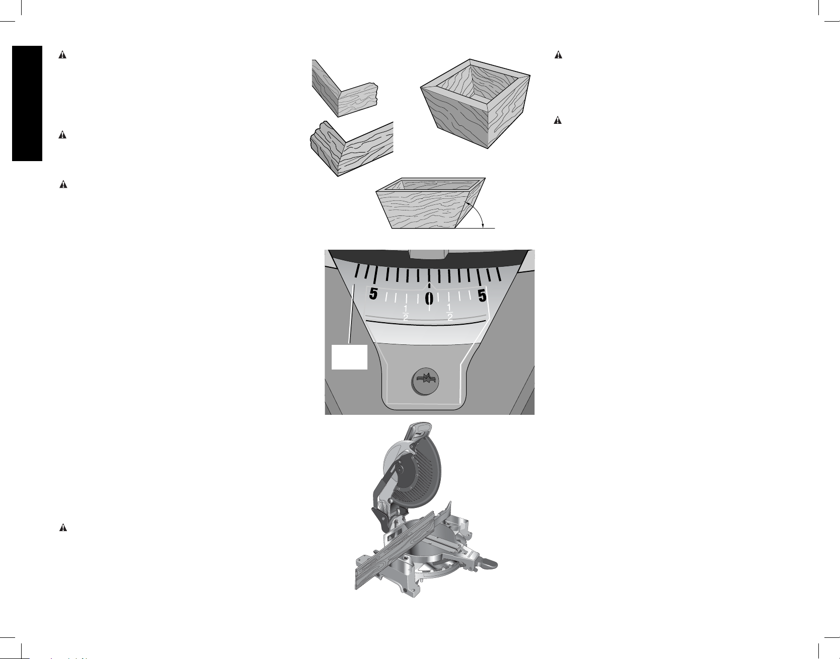
Your saw is the perfect tool for mitering corners like the
one shown in Figure 17. Sketch A in Figure 17 shows
a joint made by using the bevel adjustment to bevel the
edges of the two boards at 45° each to produce a 90°
corner. For this joint the miter arm was locked in the zero
position and the bevel adjustment was locked at 45°. The
wood was positioned with the broad flat side against the
table and the narrow edge against the fence. The cut could
also be made by mitering right and left with the broad
surface against the fence.
CUTTING TRIM MOLDING AND OTHER FRAMES
Sketch B in Figure 17 shows a joint made by setting the
miter arm at 45° to miter the two boards to form a 90°
corner. To make this type of joint, set the bevel adjustment
to zero and the miter arm to 45°. Once again, position the
wood with the broad flat side on the table and the narrow
edge against the fence.
The two sketches in Figure 17 are for four sided objects
only.
As the number of sides changes, so do the miter and
bevel angles. The chart below gives the proper angles for
a variety of shapes. The chart assumes that all sides are
of equal length. For a shape that is not shown in the chart,
use the following formula. 180° divided by the number of
sides equals the miter or bevel angle.
10
Page 13
NO. SIDES ANGLE MITER OR BEVEL
- EXAMPLES -
4 45°
5 36°
6 30°
7 25.7°
8 22.5°
9 20°
10 18°
CUTTING COMPOUND MITERS
A compound miter is a cut made using a miter angle and a
bevel angle at the same time. This is the type of cut used
to make frames or boxes with slanting sides like the one
shown in Figure 18.
NOTE: If the cutting angle varies from cut to cut, check that
the bevel clamp knob and the miter lock knob are securely
tightened. These knobs must be tightened after making
any changes in bevel or miter.
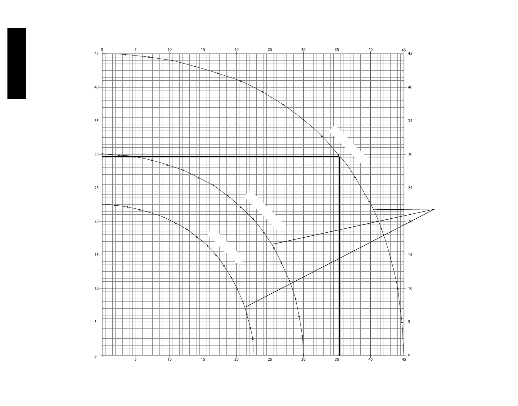
The chart shown on page 16 will assist you in selecting
the proper bevel and miter settings for common compound
miter cuts. To use the chart, select the desired angle “A”
(Figure 19) of your project and locate that angle on the
appropriate arc in the chart. From that point follow the
chart straight down to find the correct bevel angle and
straight across to find the correct miter angle.
Set your saw to the prescribed angles and make a few
trial cuts. Practice fitting the cut pieces together until you
develop a feel for this procedure and feel comfortable with
it.
EXAMPLE: To make a 4 sided box with 26° exterior
angles (Angle A, Figure 19), use the upper right arc. Find
26° on the arc scale. Follow the horizontal intersecting
line to either side to get miter angle setting on saw (42°).
Likewise, follow the vertical intersecting line to the top or
bottom to get the bevel angle setting on the saw (18°).
Always try cuts on a few scrap pieces of wood to verify
settings on saw.
MITER SCALE
The scale is used when calculating angles. To calculate
the proper miter angle, divide 180° by the number of sides
of the box or frame. Refer to the chart on page 11 for some
examples.
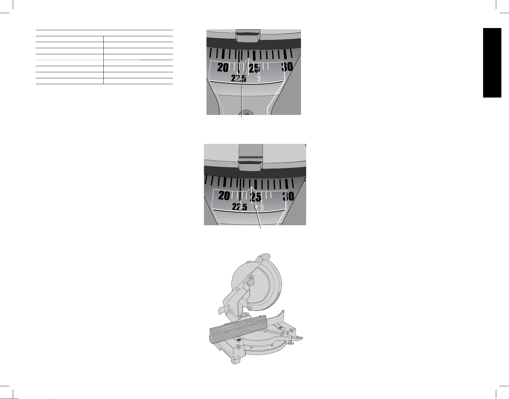
VERNIER SCALE (FIG. 23, 24)
Your saw is equipped with a vernier scale for added
precision. The vernier scale allows you to accurately set
miter angles to the nearest 1/4° (15 minutes). To use the
vernier scale follow the steps listed below.
(As an example, let’s assume that the angle you want to
miter is 24-1/4° right).
1. Turn off miter saw.
2. Set the miter angle to the nearest whole degree desired
by aligning the center mark in the vernier scale, shown
in Figure 23, with the whole degree number etched in
FIG. 23
CENTER MARK ON VERNIER SCALE ALIGNS WITH
DESIRED WHOLE ANGLE ON MITER SCALE
(24° RIGHT MITER)
FIG. 24
1/4° VERNIER MARK ALIGNS WITH CLOSEST WHOLE
DEGREE MARK ON MITER SCALE (24-1/4° RIGHT MITER)
FIG. 25
the miter scale. Examine Figure 23 closely; the setting
shown is 24º right miter.
3. To set the additional 1/4°, squeeze the miter arm lock
and carefully move the arm to the RIGHT until the 1/4°
vernier mark aligns with the CLOSEST degree mark
on the miter scale. In our example, the closest degree
mark on the miter scale happens to be 25°. Figure 24
shows a setting of 24-1/4° right miter.
For settings that require partial degrees (1/4, 1/2, 3/4°)
align the desired vernier mark with the CLOSEST degree
mark on the miter scale, as described above. (The plastic
vernier plate is inscribed with marks for 1/4, 1/2, 3/4 and 1°.
Only the 1/2° is numerically labeled.)
WHEN MITERING TO THE RIGHT
To increase the miter angle when mitering to the right,
move the arm to align the appropriate vernier mark with the
closest mark on the miter scale to the right. To decrease
the miter angle when mitering to the right, move the arm to
align the appropriate vernier mark with the closest mark on
the miter scale to the left.
WHEN MITERING TO THE LEFT
To increase the miter angle when mitering to the left, move
the arm to align the appropriate vernier mark with the
closest mark on the miter scale to the left. To decrease the
miter angle when mitering to the left, move the arm to align
the appropriate vernier mark with the closest mark on the
miter scale to the right.
CUTTING BASE MOLDING
ALWAYS MAKE A DRY RUN WITHOUT POWER BEFORE
MAKING ANY CUTS.
Straight 90° cuts :
Position the wood against the fence as shown in
Figure 21. Turn on the saw, allow the blade to reach full
speed and lower the arm smoothly through the cut.
CUTTING BASE MOLDING UP TO 3.5" (88.9 mm)
HIGH VERTICALLY AGAINST THE FENCE
Position molding as shown in Figure 25.
All cuts are made with the back of the molding against the
fence and bottom of the molding against the base.
INSIDE CORNER: OUTSIDE CORNER:
Left side Left side
1. Miter left 45° 1. Miter right at 45°
2. Save left side of cut 2. Save left side of cut
Right side Right side
1. Miter Right 45° 1. Miter left at 45°
2. Save right side of cut 2. Save right side of cut
Material up to 3.5" (88.9 mm) can be cut as described
above. For wider boards [up to 4.25" (107.95 mm)] several
minor concessions must be made.
When cutting a board between 3.5" (88.9 mm) and 4.25"
(107.95 mm) in width the roller on the tip of the guard could
English
11
Page 14
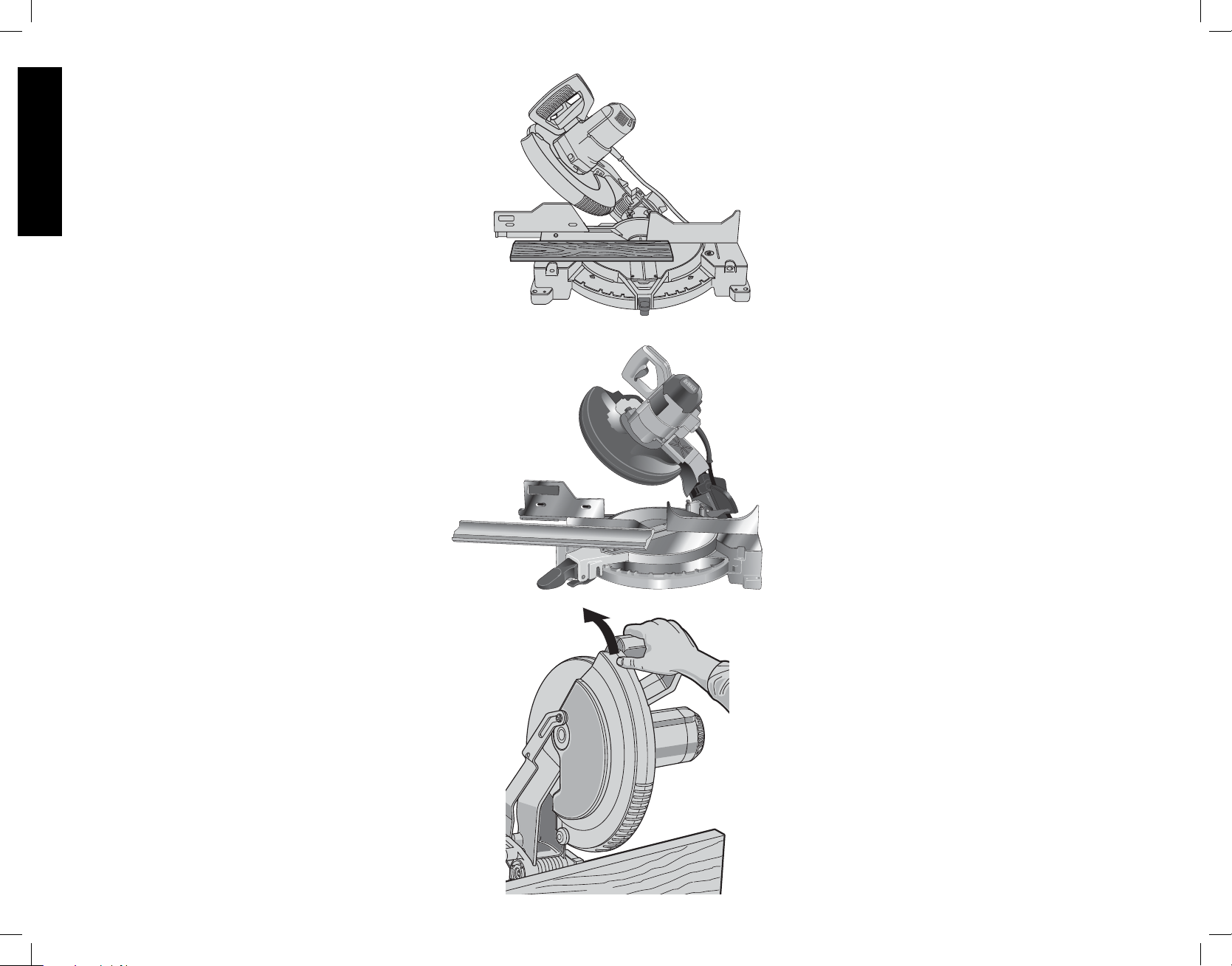
hang up on the workpiece. If this occurs, simply place your
right thumb on the upper side of the guard and roll the
guard up just enough to clear the workpiece, as shown in
Figure 28. Once you have cleared the workpiece, you can
release the guard and it will continue to open as the cut
progresses.
When mitering to the right side of a base molding wider
English
than 3.5" (88.9 mm) standing vertically against the fence
as in Figure 25, the saw can only cut through the board up
to 1 inch from the end of the board. Trying to cut more than
an inch will cause the saw’s gear case to interfere with the
workpiece. If you want to cut base molding between 3-1/2"
(88.9 mm) and 4.25" (107.95 mm) wide vertically follow
the directions below.
CUTTING 3.5" (88.9 mm)– 4.25" (107.95 mm) BASE
MOLDING VERTICALLY AGAINST THE FENCE
• Position molding as shown in Figure 25.
• All cuts made with the back of the molding against the
fence
INSIDE CORNER:
Left side
1. Position molding with bottom of molding against
the base of the saw
2. Miter left 45°
3. Save left side of cut
Right side
1. Position molding with top of the molding resting on
the base of the saw
2. Miter left 45°
3. Save left side of cut
OUTSIDE CORNER:
Left side
1. Position molding with bottom of molding against
the base of the saw
2. Miter right 45°
3. Save left side of cut
NOTE: If the cut must be made somewhere other than
1" from the end of the molding: cut off the molding at
90° approx. 1" (25.4 mm) longer than your final length
then make the miter cut as described above.
Right side
1. Position molding with bottom of the molding
against the base of the saw
2. Miter left 45°
3. Save the right side of cut
A third method of making the cut necessary is to make a
zero degree miter, 45° bevel cut. Your saw can cut a bevel
6.2" (157.5 mm) wide.
CUTTING BASE MOLDING LAYING FLAT AND USING
THE BEVEL FEATURE
• All cuts made with the saw set at 45° bevel and 0
miter.
FIG. 26
FIG. 27
FIG. 28
• All cuts made with back of molding laying flat on the
saw as shown in Figures 26.
• Move the left side fence out of the path of the blade
before attempting any of the following cuts.
INSIDE CORNER:
Left side
1. Position molding with top of molding against the fence
2. Save left side of cut
Right side
1. Position molding with bottom of the molding against
the fence
2. Save left side of cut
OUTSIDE CORNER:
Left side
1. Position molding with bottom of the molding against
the fence
2. Save right side of cut
Right side
1. Position molding with top of molding against the
fence
2. Save right side of cut
CUTTING CROWN MOLDING
Your miter saw is better suited to the task of cutting
crown molding than any tool made. In order to fit
properly, crown molding must be compound mitered with
extreme accuracy.
The two flat surfaces on a given piece of crown molding
are at angles that, when added together, equal exactly 90°.
Most, but not all, crown molding has a top rear angle (the
section that fits flat against the ceiling) of 52° and a bottom
rear angle (the part that fits flat against the wall) of 38°.
Your miter saw has special pre-set miter detent points at
31.62° left and right for cutting crown molding at the proper
angle (Fig. 27). There is also a mark on the Bevel scale
at 33.85°.
The chart below gives the proper settings for cutting crown
molding. (The numbers for the miter and bevel settings are
very precise and are not easy to accurately set on your
saw.) Since most rooms do not have angles of precisely
90°, you will have to fine tune your settings anyway.
PRETESTING WITH SCRAP MATERIAL IS
EX TREME LY IMPORTANT!
FOR CUTTING CROWN MOLDING LAYING
FLAT AND USING THE COMPOUND FEATURES
1. Move the left side fence out of the path of the blade
before attempting any of the following cuts.
2. Molding laying with broad back surface down flat on
saw table (Fig. 29).
3. The settings below are for all Standard (U.S.) crown
molding with 52° and 38° angles.
12
Page 15
BEVEL SETTING TYPE OF CUT
LEFT SIDE, INSIDE CORNER:
33.85°
1. Top of molding against fence
2. Miter table set right 31.62°
3. Save left end of cut
RIGHT SIDE, INSIDE CORNER:
33.85°
1. Bottom of molding against fence
2. Miter table set left 31.62°
3. Save left end of cut
LEFT SIDE, OUTSIDE CORNER:
33.85°
1. Bottom of molding against fence
2. Miter table set left 31.62°
3. Save right end of cut
RIGHT SIDE, OUTSIDE CORNER:
33.85°
1. Top of molding against fence
2. Miter table set right 31.62°
3. Save right end of cut
When setting bevel and miter angles for all compound
miters, remember that:
The angles presented for crown moldings are very
precise and difficult to set exactly. Since they can
easily shift slightly and very few rooms have exactly
square corners, all settings should be tested on scrap
molding.
PRETESTING WITH SCRAP MATERIAL IS
EXTREME LY IMPORTANT!
ALTERNATIVE METHOD FOR CUTTING CROWN
MOLDING
Place the molding on the table at an angle between the
fence and the saw table, as shown in Figure 30. Use of
the crown molding fence accessory (DW7084) is highly
recommended because of its degree of accuracy and
convenience. The crown molding fence accessory is
available at extra cost from your local dealer.
The advantage to cutting crown molding using this method
is that no bevel cut is required. Minute changes in the miter
angle can be made without affecting the bevel angle. This
way, when corners other than 90° are encountered, the
saw can be quickly and easily adjusted for them. Use the
crown molding fence accessory (DW7084) to maintain the
angle at which the molding will be on the wall.
INSTRUCTIONS FOR CUTTING CROWN MOLDING
ANGLED BETWEEN THE FENCE AND BASE OF
THE SAW FOR ALL CUTS
1. Angle the molding so the bottom of the molding (part
which goes against the wall when installed) is against
the fence and the top of the molding is resting on the
base of the saw, as shown in Figure 30.
2. The angled “flats” on the back of the molding must rest
squarely on the fence and base of the saw.
FIG. 29
FENCE
TABLE
CROWN MOLDING FLAT ON TABLE AND
FIG. 30
FENCE
CROWN MOLDING BETWEEN FENCE AND TABLE
AGAINST FENCE
BOTTOM SIDE
OF MOLDING
TOP SIDE
OF MOLDING
DW 7084 CROWN
MOLDING FENCE
TABLE
INSIDE CORNER: OUTSIDE CORNER:
Left side Left side
1. Miter right at 45° 1. Miter left at 45°
2. Save right side of cut 2. Save right side of cut
Right side Right side
1. Miter left at 45° 1. Miter right at 45°
2. Save left side of cut 2. Save left side of cut
FIG. 31
BLADE
FENCE
FIG. 32
FENCE
RIGHT
BLADE
WRONG
Special Cuts
NEVER MAKE ANY CUT UNLESS THE MATERIAL IS
SECURED ON THE TABLE AND AGAINST THE FENCE.
ALUMINUM CUTTING
ALWAYS USE THE APPROPRIATE SAW BLADE MADE
ESPECIALLY FOR CUTTING ALUMINUM. These are
available at your local DEWALT retailer or DEWALT service
center. Certain workpieces, due to their size, shape or
surface finish, may require the use of a clamp or fixture to
prevent movement during the cut. Position the material so
that you will be cutting the thinnest cross section, as shown
in Figure 31. Figure 32 illustrates the wrong way to cut these
extrusions. Use a stick wax cutting lubricant when cutting
aluminum. Apply the stick wax directly to the saw blade
before cutting. Never apply stick wax to a moving blade.
English
13
Page 16
The wax, available at most hardware stores and industrial
mill supply houses, provides proper lubrication and keeps
chips from adhering to the blade.
Be sure to properly secure workpiece. Refer to page 4
correct saw blade.
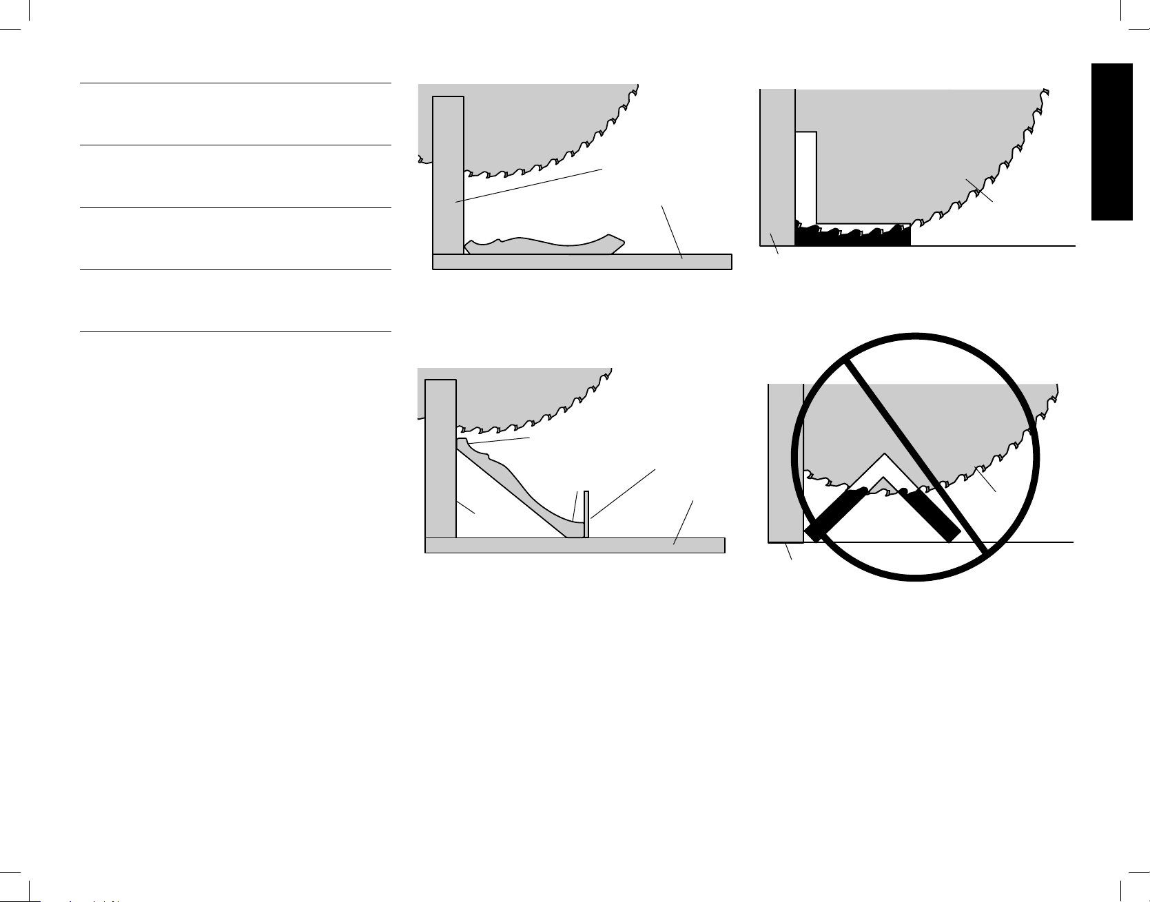
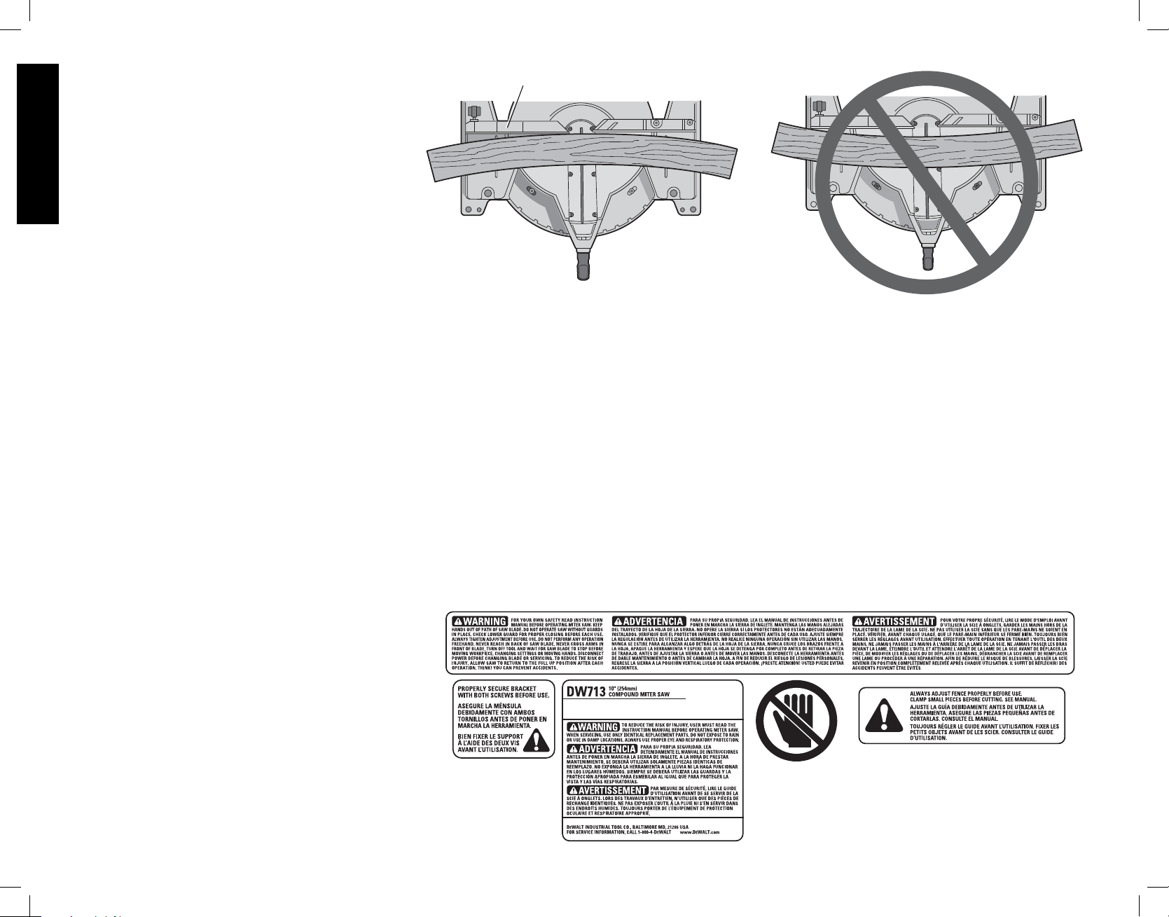
BOWED MATERIAL
When cutting bowed material always position it as shown
English
in Figure 33 and never like that shown in Figure 34.
Positioning the material incorrectly will cause it to pinch the
blade near the completion of the cut.
CUTTING PLASTIC PIPE OR OTHER ROUND
MATERIAL
Plastic pipe can be easily cut with your saw. It should be
cut just like wood and CLAMPED OR HELD FIRMLY
TO THE FENCE TO KEEP IT FROM ROLLING. This is
extremely important when making angle cuts.
CUTTING LARGE MATERIAL
Occasionally you will encounter a piece of wood a little too
large to fit beneath the blade guard. A little extra height
can be gained by rolling the guard up out of the way, as
shown in Figure 28. Avoid doing this as much as possible,
but if need be, the saw will operate properly and make the
bigger cut. NEVER TIE, TAPE, OR OTHERWISE HOLD
THE GUARD OPEN WHEN OPERATING THIS SAW.
MAINTENANCE
DO NOT use lubricants or cleaners (particularly spray
or aerosol) in the vicinity of the plastic guard. The
polycarbonate material used in the guard is subject to
attack by certain chemicals.
1. All bearings are sealed. They are lubricated for life and
need no further maintenance.
2. Periodically clean all dust and wood chips from around
AND UNDER the base and the rotary table. Even
though slots are provided to allow debris to pass
through, some dust will accumulate.
3. The brushes are designed to give you several years
of use. To replace the brushes refer to Brushes on
page 8 or return the tool to the nearest service center
for repair. A list of service center locations is packed
with your tool.
SERVICE INFORMATION
Please have the following information available for all
service calls:
Model Number ___________ Serial Number __________
Date and Place of Purchase ______________________
Repairs
To assure product SAFETY and RELIABILITY, repairs,
maintenance and adjustment should be performed by a
D
EWALT factory service center, a DEWALT authorized
service center or other qualified service personnel. Always
use identical replacement parts.
FIG. 33
FENCE
FIG. 34
for
CORRECT
INCORRECT
Three Year Limited Warranty
DEWALT will repair, without charge, any defects due
to faulty materials or workmanship for three years from
the date of purchase. This warranty does not cover part
failure due to normal wear or tool abuse. For further detail
of warranty coverage and warranty repair information,
visit www.dewalt.com or call 1-800-4-D
433-9258). This warranty does not apply to accessories
or damage caused where repairs have been made or
attempted by others. This warranty gives you specific legal
rights and you may have other rights which vary in certain
states or provinces.
In addition to the warranty, D
EWALT tools are covered by
EWALT (1-800-
If you are not completely satisfied with the performance of
your D
you can return it within 90 days from the date of purchase
with a receipt for a full refund – no questions asked.
LATIN AMERICA: This warranty does not apply to products
sold in Latin America. For products sold in Latin America,
see country specific warranty information contained either
in the packaging, call the local company or see website for
warranty information.
FREE WARNING LABEL REPLACEMENT: If your warning
labels become illegible or are missing, call 1-800-4-D
(1-800-433-9258) for a free replacement.
90 DAY MONEY BACK GUARANTEE
EWALT Power Tool, Laser, or Nailer for any reason,
EWALT
our:
1 YEAR FREE SERVICE
EWALT will maintain the tool and replace worn parts
D
caused by normal use, for free, any time during the first
year after purchase.
14
Page 17

Troubleshooting Guide
BE SURE TO FOLLOW SAFETY RULES AND INSTRUCTIONS
TROUBLE! WHAT’S WRONG? WHAT TO DO
Saw will not start
Saw makes unsatisfactory cuts
Blade does not come up to speed
Machine vibrates excessively
Does not make accurate miter cuts
Material pinches blade
1. Saw not plugged in 1. Plug in saw.
2. Fuse blown or circuit breaker
tripped
3. Cord damaged 3. Have cord replaced by authorized service center.
4. Brushes worn out 4. Have brushes replaced by authorized service center or replace
1. Dull blade 1. Replace blade, see page 5.
2. Blade mounted backwards 2. Turn blade around, see page 6.
3. Gum or pitch on blade 3. Remove blade and clean with turpentine and coarse steel wool
4. Incorrect blade for work being done 4. Change the blade type, see page 4.
1. Extension cord too light or too long 1. Replace with adequate size cord, see page 1.
2. Low house current 2. Contact your electric company.
1. Saw not mounted securely to stand
or work bench
2. Stand or bench on uneven floor 2. Reposition on flat level surface, see page 5.
3. Damaged saw blade 3. Replace blade, see page 5.
1. Miter scale not adjusted correctly 1. Check and adjust, see page 6.
2. Blade is not square to fence 2. Check and adjust, see page 6.
3. Blade is not perpendicular to table 3. Check and adjust fence, see page 6.
4. Workpiece moving 4. Clamp workpiece securely to fence
1. Cutting bowed material 1. Position bowed material as shown on page 13.
2. Replace fuse or reset circuit breaker.
them yourself as instructed on page 8.
or household oven cleaner
1. Tighten all mounting hardware, see page 5.
English
15
Page 18
English
TABLE 1: COMPOUND MITER CUT
(POSITION WOOD WITH BROAD FLAT SIDE ON THE TABLE AND THE NARROW EDGE AGAINST THE FENCE)
10
20
30
40
SQUARE BOX
50
10
20
30
60
10
20
30
SET THIS MITER ANGLE ON SAW
40
6-SIDED BOX
50
8-SIDED BOX
40
60
50
60
70
80
SET THIS BEVEL ANGLE ON SAW
70
ANGLE OF SIDE OF BOX (ANGLE A)
70
80
80
16
Page 19

Table des matières
DÉFINITIONS : LIGNES DIRECTRICES EN MATIÈRE DE SÉCURITÉ .....................18
CONSIGNES DE SÉCURITÉ IMPORTANTES ..............................................................18
INSTRUCTIONS RELATIVES À LA DOUBLE ISOLATION
ET À LA FICHE POLARISÉE ..........................................................................................18
DIRECTIVES DE SÉCURITÉ POUR TOUS LES OUTILS ............................................18
RÈGLES DE SÉCURITÉ SUPPLÉMENTAIRES ............................................................19
CONNEXION ÉLECTRIQUE ..........…………………………………………………………21
DÉBALLAGE DE LA SCIE ......... ……………………………………………………………21
FAMILIARISATION ...... ………………………………………………………………………21
FICHE TECHNIQUE .... ………………………………………………………………………21
ACCESSOIRES FACULTATIFS ……………………………………………………………21
ACCESSOIRES ...............................................................................................................22
MONTAGE SUR ÉTABLI ……………………………………………………………………22
CHANGEMENT OU POSE D’UNE LAME DE SCIE NEUVE ...…………………………23
TRANSPORT DE LA SCIE ............…………………………………………………………24
FONCTIONNEMENT .......................................................................................................26
DÉTENTE .................................................................................................................26
COUPE À L’AIDE DE VOTRE SCIE .......................................................................26
COUPES TRANSVERSALES ....................................................................................26
COUPES EN BISEAU ................................................................................................ 27
QUALITÉ DE COUPE ................................................................................................27
POSITION DU CORPS ET DES MAINS ................................................................... 28
FIXATION DE LA PIÈCE .........................................................................................28
INSTALLATION DE LA BRIDE .................................................................................. 28
SOUTIEN DES PIÈCES LONGUES .......................................................................29
DÉCOUPE DE CADRES, DE COFFRAGES
ET D’AUTRES OBJETS À QUATRE FACES .........................................................29
COUPE DE MOULURES DE GARNISSAGE ET D’AUTRES CADRES................29
COUPE À ONGLETS MIXTES ................................................................................29
ÉCHELLE À ONGLETS ...........................................................................................29
Français
RÉGLAGES ............. …………………………………………………………………………24
RÉGLAGE DE L’ÉCHELLE D’ONGLETS ...............................................................24
RÉGLAGE DU POINTEUR D’ONGLET ..................................................................24
RÉGLAGE DU BISEAU EN ÉQUERRE AVEC LA TABLE ....................................24
POINTEUR DE BISEAU ..........................................................................................24
BUTÉE DE BISEAU .................................................................................................24
RÉGLAGE DU GUIDE …………………………………………………………………25
ACTIVATION ET VISIBILITÉ DU PARE-MAIN .......................................................25
FREIN ÉLECTRIQUE AUTOMATIQUE ..................................................................25
RÉGLAGE DU VERROUILLAGE DE L’ONGLET ...................................................26
BALAIS ..............………………………………………………………………………………26
ÉCHELLE À VERNIER .............................................................................................. 29
POUR L’ASSEMBLAGE EN ONGLET À DROITE .................................................30
POUR L’ASSEMBLAGE EN ONGLET À GAUCHE ................................................30
COUPE DE MOULURE D’EMBASE .......................................................................30
COUPE DE MOULURE COURONNÉE ..................................................................31
COUPES SPÉCIALES.....................................................................................................32
ENTRETIEN .....................................................................................................................33
RÉPARATIONS ...............................................................................................................33
GARANTIE .......................................................................................................................33
GUIDE DE DÉPANNAGE................................................................................................34
TABLEAU DE RÉFÉRENCE POUR COUPE À ONGLETS MIXTES ............................35
17
Page 20

Définitions : Lignes directrices en
matière de sécurité
Les définitions ci-dessous décrivent le niveau de gravité pour chaque symbole. Veuillez lire
le mode d’emploi et porter une attention particulière à ces symboles.
DANGER : Indique une situation dangereuse imminente qui, si elle n’est pas évitée,
causera la mort ou des blessures graves.
AVERTISSEMENT :
pas évitée, pourrait se solder par un décès ou des blessures graves.
ATTENTION : Indique une situation potentiellement dangereuse qui, si elle n’est pas
évitée pourrait se solder par des blessures mineures ou modérées.
AVIS : Indique une pratique ne posant aucun risque de dommages corporels mais
qui par contre, si rien n’est fait pour l’éviter, pourrait poser des risques de dommages
matériels.
POUR TOUTE QUESTION OU TOUT COMMENTAIRE SUR CET OUTIL OU SUR
TOUT AUTRE OUTIL DeWALT, COMPOSER LE NUMÉRO SANS FRAIS SUIVANT :
1-800-4-D
EWALT (1-800-433-9258).
Indique une situation potentiellement dangereuse qui, si elle n’est
CONSIGNES DE SÉCURITÉ IMPORTANTES
AVERTISSEMENT : Lire toutes les directives avant d’utiliser le produit.
Négliger de suivre toutes les directives suivantes peut entraîner des
risques de chocs électriques, d’incendie et/ou de blessures graves.
LIRE TOUTES CES DIRECTIVES
Double isolation
Les outils à double isolation comportent partout deux couches d’isolation électrique
séparées ou une double épaisseur de matériau isolant entre l’opérateur et le système
électrique de l’outil. Les outils comportant ce système d’isolation ne sont pas conçus pour
être mis à la terre. L’outil est donc doté d’une prise à deux broches qui permet d’utiliser
Français
des rallonges sans avoir à se soucier de maintenir une connexion à la terre.
REMARQUE : la double isolation ne remplace pas les précautions normales de sécurité
lors de l’utilisation de cet outil. Le système d’isolation sert à apporter une protection
accrue contre toute blessure résultant d’une défaillance d’isolation électrique potentielle à
l’intérieur de l’outil.
ATTENTION : EN CAS DE RÉPARATION, UTILISER UNIQUEMENT DES PIÈCES
DE RECHANGE IDENTIQUES. Réparer ou remplacer les cordons d’alimentation
endommagés.
Fiches polarisées
Certains appareils comportent des fiches polarisées (c’est-à-dire qu’une lame est plus
large que l’autre) afin de réduire le risque de choc électrique. Lorsqu’elle est présente,
cette fiche ne se branche que d’une seule façon dans une prise de courant polarisée. Si
la fiche ne s’insère pas totalement dans la prise de courant, l’inverser. Si elle ne s’insère
toujours pas dans la prise, demander à un électricien compétent d’installer une fiche
polarisée. Ne pas remplacer la fiche.
Consignes de sécurité pour tous les outils
Cette scie à onglets est compatible avec la lampe de travail et le laser DEWALT.
AVERTISSEMENT : TOUJOURS utiliser une protection oculaire lors de l’utilisation
de la scie à onglets pour réduire le risque de blessures aux yeux.
• MAINTENIR LE PROTÈGE-LAME EN PLACE et en état de fonctionnement.
• RETIRER LES CLÉS À MOLETTE ET LES CLÉS DE RÉGLAGE. S’habituer à vérifier
si les clés à molette et les clés de réglage sont retirées de la broche avant de mettre
l’outil sous tension. Des outils, des déchets de découpe et d’autres débris peuvent être
projetés à grande vitesse, provoquant des blessures.
• GARDER LA ZONE DE TRAVAIL PROPRE. Les zones et établis encombrés sont
souvent des causes d’accidents.
• NE PAS UTILISER L’APPAREIL DANS UN ENVIRONNEMENT DANGEREUX.
L’utilisation d’outils électriques dans des endroits humides ou mouillés ou sous la pluie
peut provoquer un choc électrique ou une électrocution. Tenir la zone de travail bien
éclairée pour éviter de trébucher ou de mettre bras, mains et doigts en danger.
• TENIR LES ENFANTS À L’ÉCART. Tous les visiteurs doivent se trouver à une distance
sûre de la zone de travail. Un atelier représente un environnement potentiellement
dangereux.
• S’ASSURER QUE L’ATELIER NE PRÉSENTE PAS DE DANGER POUR LES
ENFANTS : utiliser des cadenas, des interrupteurs principaux ou retirer les clés de
démarrage. Le démarrage non autorisé d’un appareil par un enfant ou un visiteur
pourrait se solder par des blessures.
• NE PAS FORCER L’OUTIL. Le travail sera mieux accompli et sera moins dangereux
au rythme prévu pour l’appareil.
• UTILISER L’OUTIL APPROPRIÉ. Ne pas forcer un outil ou un accessoire pour
effectuer un travail auquel il n’a pas été conçu. L’utilisation d’un outil ou d’un accessoire
inapproprié pourrait se solder par des blessures corporelles.
• PORTER LES VÊTEMENTS APPROPRIÉS. Ne pas porter ni vêtement ample, ni gant,
ni cravate, ni bague, ni bracelet, ni autre bijou, car ces derniers pourraient s’enchevêtrer
dans des pièces mobiles. Des souliers antidérapants sont recommandés. Se couvrir
les cheveux s’ils sont longs. Se tenir éloigné des évents, car ces derniers pourraient
camoufler des pièces mobiles.
• TOUJOURS PORTER DES LUNETTES DE SÉCURITÉ. Les lunettes ordinaires ne
constituent PAS des lunettes de sécurité. Utiliser également un masque facial ou
antipoussière si l’opération de découpe génère de la poussière. TOUJOURS PORTER
UN ÉQUIPEMENT DE SÉCURITÉ HOMOLOGUÉ :
• protection oculaire conforme à la norme ANSI Z87.1 (CAN/CSA Z94.3);
• protection auditive conforme à la norme ANSI S12.6 (S3.19);
• protection des voies respiratoires conforme aux normes NIOSH/OSHA/MSHA.
• FIXER LA PIÈCE. Utiliser des brides de fixation ou un étau pour maintenir la pièce sur
la table et contre le guide. Faire de même lorsque le travail à effectuer exigera que la
main de l’opérateur se trouve très proche de la lame (à moins de 152 mm [6 po]). Une
telle pratique est plus sécuritaire, car l’opérateur peut utiliser ses deux mains pour faire
fonctionner l’outil.
• NE PAS TROP TENDRE LES BRAS. Conserver son équilibre en tout temps. Une
perte d’équilibre risque d’entraîner une blessure corporelle.
• PRENDRE SOIN DES OUTILS. S’assurer que les outils sont aiguisés et propres
afin d’optimiser sécurité et performance. Suivre les consignes de graissage et
de changement d’accessoires. Les machines et outils mal entretenus peuvent
s’endommager davantage et/ou provoquer des blessures.
• ÉTEINDRE L’APPAREIL ET COUPER LE COURANT avant d’installer ou de retirer
des accessoires, avant de réaliser ou de modifier un réglage et lors de réparations
ou de déplacements de l’appareil. Un démarrage accidentel peut provoquer des
blessures. Ne pas toucher aux lames métalliques de la fiche lors du branchement ou
du débranchement du cordon d’alimentation.
• RÉDUIRE LE RISQUE DE DÉMARRAGE ACCIDENTEL. S’assurer que l’interrupteur
se trouve sur la position « ARRÊT » avant de brancher le cordon d’alimentation.
• UTILISER UNE RALLONGE APPROPRIÉE. S’assurer que la rallonge est en bon état.
Si le produit est doté d’un cordon amovible, utiliser uniquement une rallonge à 3 fils
pourvue d’une fiche de mise à la terre à 3 lames et d’une prise à 3 fentes correspondant
à la fiche de l’outil. Lorsqu’une rallonge est utilisée, s’assurer d’utiliser un calibre
suffisamment élevé pour assurer le transport du courant nécessaire au fonctionnement
de l’appareil. Une rallonge de calibre inférieur causera une chute de tension de ligne et
18
Page 21

donc une perte de puissance et une surchauffe. Le tableau suivant indique le calibre
approprié à utiliser selon la longueur de la rallonge et l’intensité nominale de la plaque
signalétique. En cas de doute, utiliser le calibre supérieur suivant. Plus le numéro de
calibre est petit, plus le cordon est de calibre élevé.
Calibre minimum pour rallonge
Volts
Intensité nominale
Plus de Pas plus de AWG
0 6 5,5 (18) 4,9 (16) 4,9 (16) 4,3 (14)
6 10 5,5 (18) 4,9 (16) 4,3 (14) 3,7 (12)
10 12 4,9 (16) 4,9 (16) 4,3 (14) 3,7 (12)
12 16 4,3 (14) 3,7 (12) Non recommandé
• VÉRIFIER QUE LES PIÈCES NE SONT PAS ENDOMMAGÉES. Avant toute
utilisation ultérieure de l’outil, un protège-lame (ou une autre pièce) endommagé doit
être soigneusement examiné afin de déterminer s’il fonctionnera correctement et
remplira sa fonction prévue – vérifier l’alignement des pièces mobiles, la présence de
grippage des pièces mobiles, de rupture de pièces, la fixation et tout problème pouvant
nuire au fonctionnement de l’outil. Un protège-lame (ou toute autre pièce) endommagé
doit être réparé et remplacé adéquatement. Ne pas utiliser l’appareil si l’interrupteur ne
fonctionne pas.
• UTILISER LES ACCESSOIRES RECOMMANDÉS. N’utiliser que les accessoires
conseillés par le fabricant pour le modèle de l’outil. Des accessoires qui conviennent
à un outil pourraient être dangereux lorsqu’ils sont utilisés avec un autre outil. Une
liste des accessoires recommandés se trouve dans le mode d’emploi. L’utilisation
d’accessoires incorrects peut entraîner un risque de blessure corporelle.
• NE JAMAIS SE TENIR SUR L’OUTIL. Une blessure grave pourrait se produire en cas
de basculement de l’outil ou de démarrage accidentel de l’outil de découpe.
• NE JAMAIS LAISSER L’OUTIL FONCTIONNER SANS SURVEILLANCE. ÉTEINDRE
L’APPAREIL. Ne pas laisser l’outil tant qu’il n’est pas complètement arrêté. De graves
blessures pourraient survenir.
• NE PAS UTILISER D’OUTILS ÉLECTRIQUES À PROXIMITÉ DE LIQUIDES
INFLAMMABLES OU DANS UNE ATMOSPHÈRE GAZEUSE OU EXPLOSIVE. Les
moteurs de ces outils peuvent provoquer des étincelles et enflammer des vapeurs.
• ÊTRE VIGILANT, SURVEILLER LE TRAVAIL EFFECTUÉ ET FAIRE PREUVE DE
JUGEMENT. NE PAS UTILISER L’APPAREIL EN CAS DE FATIGUE OU SOUS
L’INFLUENCE DE DROGUES, D’ALCOOL ou DE MÉDICAMENTS. En effet,
un moment d’inattention en utilisant des outils électriques peut se solder par des
blessures.
120V
240V
Longueur totale du cordon
en mètres (en pieds)
7,6 (25) 15,2 (50) 30,5 (100) 45,7 (150)
15,2 (50) 30,5 (100) 61,0 (200) 91,4 (300)
Règles de sécurité supplémentaires pour les
scies à onglets
AVERTISSEMENT : Ne pas laisser une bonne connaissance de l’outil (acquise par
l’utilisation fréquente de la scie) prendre préséance sur les règles de sécurité. Toujours se
souvenir qu’une fraction de seconde d’imprudence est suffisante pour infliger de graves
blessures.
• NE PAS FAIRE FONCTIONNER CET APPAREIL avant qu’il ne soit entièrement
assemblé et installé conformément aux directives. Un appareil mal assemblé peut
provoquer des blessures graves.
• DEMANDER CONSEIL à un superviseur, à un instructeur ou à toute autre personne
qualifiée si l’on ne maîtrise pas parfaitement l’utilisation de cet appareil. La connaissance
est synonyme de sécurité.
• STABILITÉ. S’assurer que la scie à onglets est posée sur une surface portante fixe
et ne risque pas de glisser ou de se déplacer durant son utilisation. Si le système de
mobilité est installé, relever la ou les roulettes mobiles de manière à ce que la scie soit
en position stable.
• SUIVRE TOUS LES CODES DE CÂBLAGE et les branchements électriques
recommandés afin d’éviter les chocs électriques ou l’électrocution. Il faut protéger la
ligne d’alimentation électrique avec un fusible à temporisation ou un disjoncteur d’au
moins 15 ampères.
• S’ASSURER que la lame tourne dans le bon sens. Les dents de la lame doivent pointer
dans le sens de rotation, comme il est indiqué sur la scie.
• SERRER TOUTES LES POIGNÉES DE FIXATION, les boutons et les leviers avant
l’utilisation de la scie. Si les brides sont lâches, des pièces ou la pièce à travailler
pourraient être projetées à grande vitesse.
• S’ASSURER QUE la lame au complet et les attaches de lame sont propres, que
les côtés encastrés des attaches de lame sont appuyés sur la lame et que la vis de
l’arbre est bien serrée. Un mécanisme de serrage de lame lâche ou mal installé risque
d’endommager la scie et de provoquer des blessures corporelles.
• UTILISER TOUJOURS UNE LAME TRANCHANTE. Vérifier que la lame fonctionne
bien dans l’axe et qu’elle ne vibre pas. Une lame émoussée ou une lame qui vibre peut
endommager l’appareil et/ou provoquer des blessures graves.
• NE PAS UTILISER UNE TENSION AUTRE QUE CELLE DÉSIGNÉE pour la scie.
Une tension autre risquerait d’entraîner une surchauffe, des dommages à la scie et des
blessures corporelles.
• NE PAS PLACER QUOI QUE CE SOIT CONTRE LE VENTILATEUR pour retenir
l’arbre moteur. Une telle pratique peut endommager l’outil et entraîner des blessures
corporelles.
• NE PAS forcer l’action de coupe. Le calage partiel ou complet du moteur peut causer
des dommages à l’appareil ou à la lame et/ou des blessures graves.
• LAISSER LE MOTEUR ATTEINDRE SON PLEIN RÉGIME avant de commencer la
coupe. Commencer à couper trop tôt peut endommager l’appareil ou la lame et/ou
provoquer des blessures graves.
• NE JAMAIS COUPER DE MÉTAUX FERREUX (métaux contenant du fer ou de l’acier)
ni de la maçonnerie. En coupant l’un ou l’autre de ces matériaux, les pointes carburées
peuvent se détacher de la lame, et ce, à grande vitesse. Cela peut provoquer des
blessures graves.
• NE PAS UTILISER DE MEULES ABRASIVES. La chaleur excessive et les particules
abrasives qu’elles produisent risquent d’endommager la scie et de causer des
blessures corporelles.
• AUCUNE partie du corps ne doit se trouver dans la trajectoire de la lame de la scie. Un
tel positionnement risque d’entraîner des blessures corporelles.
• NE JAMAIS appliquer de lubrifiant sur une lame en fonctionnement. L’application de
lubrifiant pourrait amener l’opérateur à déplacer ses mains jusque sur la lame et ainsi
se blesser gravement.
• IL NE FAUT PAS placer une main à proximité de la lame lorsque la scie est branchée
au bloc d’alimentation. Le fonctionnement inopiné de la lame risquerait d’entraîner des
blessures graves.
• NE PAS RÉALISER D’OPÉRATIONS À MAIN LEVÉE (pièce à travailler non soutenue
par la table et le guide). Tenir la pièce à travailler fermement contre le guide et la table.
Une opération à main levée avec une scie à onglets risquerait de projeter la pièce à
grande vitesse, provoquant ainsi des blessures graves.
• NE PAS PASSER LES MAINS AUTOUR de la lame de scie ou derrière celle-ci. Une
lame peut provoquer des blessures graves.
• IL NE FAUT PAS passer les mains sous la scie sauf si elle est hors tension et débranchée.
Tout contact avec la lame de scie pourrait entraîner des blessures corporelles.
Français
19
Page 22

• FIXER L’APPAREIL SUR UNE SURFACE DE SUPPORT STABLE. Les vibrations
sont susceptibles de faire glisser, sautiller ou basculer l’appareil, ce qui peut provoquer
des blessures graves.
• UTILISER UNIQUEMENT LES LAMES À TRONÇONNER recommandées pour les
scies à onglets. Pour des résultats optimums, ne pas utiliser de lames à pointes de
carbure avec un angle d’attaque supérieur à 7 degrés. Ne pas utiliser des lames à
dents très espacées. Celles-ci peuvent dévier et faire contact avec le protège-lame et
endommager ainsi l’appareil et/ou provoquer des blessures graves.
• UTILISER SEULEMENT DES LAMES DE DIMENSION ET DE TYPE APPROPRIÉS
prévues pour cet outil, et ce, pour éviter d’endommager l’appareil et/ou d’entraîner des
blessures graves.
• INSPECTER LA LAME POUR REPÉRER DES FISSURES ou d’autres dommages
avant l’utilisation. Une lame fissurée ou endommagée peut se détacher et des
fragments peuvent être projetés à grande vitesse, ce qui peut provoquer des blessures
graves. Remplacer les lames fissurées ou endommagées immédiatement.
• NETTOYER LA LAME ET LES ATTACHES DE LAME avant l’utilisation. Le nettoyage
de la lame et des attaches de lame permet de détecter tout dommage à la lame ou
aux attaches de lame. Une lame ou une attache de lame fissurée ou endommagée
peut se détacher et des fragments peuvent être projetés à grande vitesse, ce qui peut
provoquer des blessures graves.
• IL NE FAUT PAS utiliser de graisse ni de produits nettoyants (en particulier de
pulvérisateur ou d’aérosol) à proximité du protège-lame en plastique. Certains produits
chimiques peuvent attaquer le matériau de polycarbonate dont il est constitué.
• TOUJOURS UTILISER LA PLAQUE DE TRAIT DE SCIE ET LA REMPLACER
LORSQU’ELLE EST ENDOMMAGÉE. L’accumulation de petits copeaux sous la scie
pourrait nuire à la lame ou rendre la pièce instable lors de la découpe.
• UTILISER SEULEMENT LES ATTACHES DE LAME prévues pour cet outil afin de
prévenir tout dommage et/ou des blessures graves
• DÉGAGER LES ÉVENTS DU MOTEUR de toute sciure ou de tout copeau. Des
Français
évents de moteur obstrués peuvent provoquer la surchauffe de l’appareil, ce qui
l’endommagerait et provoquerait peut-être un court-circuit qui pourrait engendrer des
blessures graves.
• TENIR LES BRAS, LES MAINS ET LES DOIGTS éloignés de la lame afin d’éviter des
coupures graves. Fixer solidement toutes les pièces qui exigeraient que la main soit à
moins de 152 mm (6 po) de la lame de scie.
• NE JAMAIS VERROUILLER L’INTERRUPTEUR en position de « MARCHE ». Une
telle pratique peut entraîner des blessures corporelles graves.
• ÉTEINDRE L’APPAREIL et laisser la lame s’immobiliser complètement avant de
relever le bras, de nettoyer la zone de la lame, d’enlever les débris de la trajectoire de
la lame et avant l’entretien ou le réglage de l’outil. Une lame mobile peut provoquer des
blessures graves.
• SOUTENIR CORRECTEMENT LES PIÈCES LONGUES OU LARGES. La perte de
contrôle de la pièce peut provoquer des blessures.
• NE JAMAIS croiser les bras devant la lame au moment d’utiliser l’outil. Toujours
effectuer un fonctionnement à sec (non alimenté) avant de réaliser une coupe de
finition. Ainsi, la trajectoire de la lame peut être vérifiée, ce qui permet d’éviter toute
blessure corporelle grave.
• DES INFORMATIONS SUPPLÉMENTAIRES (c.-à-d., une vidéo sur la sécurité),
indiquant comment utiliser des outils électriques correctement et en toute sécurité,
sont disponibles auprès du Power Tool Institute, 1300 Sumner Avenue, Cleveland, OH
44115-2851 É.-U. (www.powertoolinstitute.com). Des renseignements sont également
offerts par le National Safety Council, 1121 Spring Lake Drive, Itasca, IL 60143-3201
É.-U. Se reporter à la norme ANSI 01.1 de l’American National Standards Institute
concernant les exigences en matière de sécurité pour les appareils de travail du bois
ainsi qu’à la réglementation OSHA 1910.213 du département du travail des É.-U.
(Department of Labor).
AVERTISSEMENT : Ne connectez pas l’appareil à une source d’alimentation électrique
tant que vous n’avez pas complètement lu et compris les instructions.
AVERTISSEMENT : Toujours porter une protection auditive appropriée
conformément à la norme ANSI S12.6 (S3.19) lors de l’utilisation du produit. Dans
certaines conditions et selon la durée d’utilisation, le bruit émis par ce produit pourrait
contribuer à une perte auditive.
AVERTISSEMENT : NE JAMAIS EFFECTUER DE COUPE SI LE MATÉRIAU N’EST
PAS MAINTENU EN PLACE SUR LA TABLE ET CONTRE LE GUIDE.
AVERTISSEMENT : Certaines poussières produites par les activités de ponçage, de
sciage, de meulage, de perçage et autres activités de construction peuvent contenir des
produits chimiques pouvant causer le cancer, des anomalies congénitales ou d'autres
problèmes liés aux fonctions reproductrices. Voici quelques exemples de ces produits
chimiques :
• le plomb contenu dans les peintures à base de plomb;
• la silice cristalline de la brique, du ciment et d'autres produits de maçonnerie; et
• l'arséniate de cuivre et de chrome provenant du bois traité chimiquement.
Les risques reliés à l'exposition à ces poussières varient selon la fréquence à laquelle
vous travaillez avec ce type de matériaux. Afin de réduire votre exposition à ces produits
chimiques : travaillez dans un endroit bien ventilé et portez un équipement de sécurité
approuvé comme un masque anti-poussières conçu spécialement pour filtrer les particules
microscopiques.
• Évitez le contact prolongé avec les poussières produites par les activités de
ponçage, sciage, meulage, perçage et autres activités de construction. Portez des
vêtements de protection et lavez les parties du corps exposées avec une solution
d'eau et de savon. Le fait de laisser la poussière pénétrer par la bouche et les yeux ou
de la laisser reposer sur la peau, peut promouvoir l'absorption de produits chimiques
nocifs.
AVERTISSEMENT : L'utilisation de cet outil peut produire ou propulser des poussières
qui pourraient causer des problèmes respiratoires graves et permanents ou d'autres
problèmes médicaux. Portez toujours un appareil respiratoire approuvé par la NIOSH/
OSHA pour vous protéger de la poussière. Dirigez les particules à l'écart de votre visage
et de votre corps.
Pour plus de commodité et de sécurité, les étiquettes de sécurité suivantes sont apposées
sur votre scie à onglet.
SUR LE BOÎTIER DU MOTEUR :
AVERTISSEMENT : POUR VOTRE SÉCURITÉ, VEUILLEZ LIRE LE MODE
D’EMPLOI AVANT D’UTILISER LA SCIE.
EN CAS DE RÉPARATION, UTILISER UNIQUEMENT DES PIÈCES DE RECHANGE
IDENTIQUES.
TOUJOURS PORTER UNE PROTECTION OCULAIRE.
PROTÉGER DE LA PLUIE ET NE PAS UTILISER DANS DES ENDROITS
HUMIDES.
GUIDE MOBILE :
TOUJOURS RÉGLER CORRECTEMENT
LE GUIDE AVANT UTILISATION. FIXER
LES PETITES PIÈCES À TRAVAILLER
AVANT DE LES COUPER. VOIR LE
MANUEL.
SUR LE PARE-MAIN :
DANGER – SE TENIR À L’ÉCART DE LA LAME.
SUR LE PARE-MAIN SUPÉRIEUR :
BIEN FIXER LE SUPPORT AVEC LES DEUX VIS, AVANT
D’UTILISER L’OUTIL.
20
Page 23

SUR LA TABLE : (2 EMPLACEMENTS)
AVERTISSEMENT : POUR VOTRE SÉCURITÉ, PRIÈRE DE LIRE LE MODE
D’EMPLOI AVANT D’UTILISER LA SCIE À ONGLETS.
GARDER LES MAINS HORS DE LA TRAJECTOIRE DE LA LAME DE LA SCIE.
NE PAS UTILISER LA SCIE SANS QUE LES PARE-MAINS NE SOIENT EN PLACE.
VÉRIFIER, AVANT CHAQUE USAGE, QUE LE PARE-MAIN INFÉRIEUR SE
FERME BIEN.
TOUJOURS BIEN SERRER LES RÉGLAGES AVANT UTILISATION. EFFECTUER
TOUTE OPÉRATION EN TENANT L’OUTIL DES DEUX MAINS.
NE JAMAIS PASSER LES MAINS À L’ARRIÈRE DE LA LAME DE LA SCIE.
NE JAMAIS PASSER LES BRAS DEVANT LA LAME. ÉTEINDRE L’OUTIL ET
ATTENDRE L’ARRÊT DE LA LAME DE LA SCIE AVANT DE DÉPLACER LA
PIÈCE, DE MODIFIER LES RÉGLAGES OU DE DÉPLACER LES MAINS.
DÉBRANCHER LA SCIE AVANT DE REMPLACER UNE LAME OU PROCÉDER À
UNE RÉPARATION.
AFIN DE RÉDUIRE LES RISQUES DE BLESSURES, LAISSER LA SCIE REVENIR
EN POSITION COMPLÈTEMENT RELEVÉE APRÈS CHAQUE UTILISATION. IL
SUFFIT DE RÉFLÉCHIR! VOUS POUVEZ EMPÊCHER LES ACCIDENTS.
SUR LE SOCLE : (À 2 ENDROITS)
Connexion électrique
S’assurer que votre bloc d’alimentation est compatible avec l’inscription de la plaque
signalétique. 120 volts, c.a. signifie que votre scie ne peut uniquement fonctionner qu’en
courant alternatif. Une diminution de tension de 10 pour cent ou plus risquera de provoquer
une perte de puissance et une surchauffe. Tous les outils D
Si l’outil ne fonctionne pas, vérifier l’alimentation.
EWALT sont testés en usine.
Déballage de la scie
Vérifier le contenu de la boîte pliante de la scie à onglets pour s’assurer que toutes les
pièces ont bien été livrées. En plus de ce mode d’emploi, le carton devrait contenir :
1. Une scie à onglets no DW713 avec lame.
2. Une clé de lame située dans la poche de clé illustrée à la figure 2.
3. Un sac à poussières no DW7053.
FIG. 1
Familiarisation
Votre scie à onglets est livrée entièrement
assemblée dans l’emballage. Ouvrir la boîte et
sortir la scie en la prenant par la poignée de
transport commode, comme indiqué à la
figure 1.
Placer la scie sur une surface lisse et plane, telle
qu’un établi ou une table solide.
Observer les figures 2 et 3 afin de vous familiariser
avec la scie et ses diverses pièces. La rubrique concernant les réglages renverra à ces
termes et il faut savoir quelles sont les
différentes pièces et où elles se trouvent.
ATTENTION : Risque de pincement. Pour réduire le risque de blessures, garder le
pouce sous la poignée lors de son abaissement. Lors de l’abaissement de la poignée, le
dispositif de protection inférieur se déplacera vers le haut et pourrait pincer l’utilisateur. La
poignée est placée près du carter pour des coupes particulières.
Appuyer légèrement sur la poignée de commande et retirer la tige de verrouillage, comme
indiqué à la figure 4. Relâcher doucement la pression vers le bas et laisser le bras se
relever complètement. Utiliser la tige de verrouillage pour transporter la scie d’un endroit à
l’autre. Pour déplacer la scie, toujours utiliser la poignée de transport ou les zones en retrait
pour la main illustrées à la figure 3.
Fiche technique
CAPACITÉ DE DÉCOUPE
Onglet à 50 °, à gauche ou à droite
Biseau de 48 ° à gauche; 3 ° à droite
Onglet à 0 °
Hauteur max. : 89 mm (3,5 po) Largeur résultante 89 mm (3,5 po)
Largeur max. : 155 mm (6,1 po) Hauteur résultante 32 mm (1,25 po)
Onglet à 45 °
Hauteur max. : 89 mm (3,5 po) Largeur résultante 61 mm (2,4 po)
Largeur max. : 107 mm (4,2 po) Hauteur résultante 32 mm (1,25 po)
Biseau à 45 °
Hauteur max. : 58,5 mm (2,3 po) Largeur résultante 89 mm (3,5 po)
Largeur max. : 155 mm (6,1 po) Hauteur résultante 19 mm (0,75 po)
Onglet à 31,62 ° et biseau à 33,85 °
Largeur max. : 133 mm (5,25 po) Hauteur résultante 23 mm (0,9 po)
ENTRAÎNEMENT
Moteur 120 V
2 200 watts Moteur de 15 A
5 000 tr/min Engrenages hélicoïdaux taillés avec roulements à billes
et à rouleaux
Lame à pointes carburées Frein électrique automatique
Accessoires facultatifs
Les accessoires suivants, conçus pour votre scie, peuvent vous être utiles. Dans certains
cas, d’autres supports de pièces, butées réglables, fixations, etc., peuvent être plus
appropriés. Sélectionner et utiliser les accessoires avec soin.
Rallonge pour support de pièce : DW7080
Le support de pièce est utilisé pour soutenir de longues pièces qui dépassent. Il est
assemblé par l’utilisateur. Votre table à scier est conçue pour accepter deux supports
de pièces, un de chaque côté.
Butée réglable : DW7051
Nécessite l’utilisation d’un support d’ouvrage (voir schéma). Elle sert à effectuer des
découpes répétitives de même longueur [comprise entre 0 et 107 cm (42 po)].
Serre-joint : DW7082
Sert à fixer fermement la pièce au guide de la scie pour une découpe de précision.
Sac à poussière : DW7053 (livré avec certains modèles)
Équipé d’une fermeture à glissière pour un vidage facile, le sac à poussière capture la
plus grande partie de la sciure produite (non illustré).
Guide de moulures couronnées : DW7084
Sert pour la découpe de précision de moulures couronnées.
Système guidé par laser : DW7187
Alimenté par la scie, le trait laser brillant améliore la visibilité dans les emplacements à
éclairage faible ou intense. Facile à installer.
Français
21
Page 24

Système de lampe de travail à DEL : DWS7085
Éclairage utilisé pour une plus grands visibilité et alignement de découpage lors du
fonctionnement. Facile à installer.
Plaque de trait de scie de rechange pour scie à onglets : DW7055
Cette plaque de plastique moulé limite le déchiquetage provoqué par la lame.
LAMES DE SCIE : TOUJOURS UTILISER DES LAMES DE SCIE DE 254 mm (10 po)
COMPORTANT DES ALÉSAGES CENTRAUX DE 16 mm (5/8 po). LE RÉGIME DOIT
ÊTRE AU MOINS DE 5 500 TR/MIN. Ne jamais utiliser de lames de diamètre inférieur.
Le pare-main ne serait pas adéquat. Utiliser uniquement des lames à tronçonner! Ne
pas utiliser de lames conçues pour un sciage rapide, de lames combinées ou de lames à
crochet d’un angle supérieur à 7º.
DESCRIPTION DES LAMES
APPLICATION DIAMÈTRE DENTS
Lames de scie de construction (fin trait de scie avec côté anticollant)
Polyvalente 254 mm (10 po) 40
Tronçonnage fin 254 mm (10 po) 60
Lames de scie pour travail du bois (fournissent des coupes propres et régulières)
Tronçonnage fin 254 mm (10 po) 80
Métaux non ferreux 254 mm (10 po) 80
REMARQUE : pour couper des métaux non ferreux, utiliser des lames de scie à
denture TCG (trapézoïdale) spécialement conçues à cet effet.
ACCESSOIRES
AVERTISSEMENT : Puisque les accessoires autres que ceux offerts par DEWALT n’ont
pas été testés avec ce produit, l’utilisation de ceux-ci avec l’outil pourrait s’avérer dangereuse.
Pour réduire le risque de blessures, utiliser exclusivement les accessoires D
recommandés avec le présent produit.
Les accessoires recommandés pour votre outil peuvent être achetés auprès du distributeur
Français
local ou d’un centre de réparation agréé. Pour toute assistance en matière d’accessoires
convenant à l’outil acheté, communiquer avec D
Road, Baltimore, MD 21286, États-Unis, composer le 1-800-4-D
EWALT Industrial Tool Co., 701 East Joppa
EWALT (1-800-433-9258) ou
visiter notre site Web à www.dewalt.com.
Montage sur établi
Les quatre pieds sont munis de trous pour faciliter le montage sur établi, comme indiqué à
la figure 2 (deux trous de taille différente sont prévus afin de recevoir des vis de différentes
tailles. Utiliser l’un des trous; (il n’est pas nécessaire d’utiliser les deux). Toujours fixer
fermement la scie afin d’empêcher tout déplacement. Pour améliorer la portabilité de l’outil,
on peut le monter sur une pièce de contreplaqué de 12,7 mm (1/2 po) ou plus d’épaisseur
et qui peut à son tour être fixée à votre support de pièce, ou déplacée vers un autre site de
travail et fixée de nouveau.
REMARQUE : Si la scie doit être fixée à une pièce de contreplaqué, s’assurer que les vis
de montage ne dépassent pas de la partie inférieure du bois. Le contreplaqué doit reposer
à plat sur le support de la pièce. Lors de la fixation de la scie à toute surface de travail, ne
la fixer que sur les brides de fixation où se situent les trous des vis de montage. L’utilisation
des brides de fixation à tout autre endroit nuira à coup sûr au fonctionnement adéquat de la
scie.
ATTENTION : Pour éviter tout grippage et manque de précision, s’assurer que la surface
de montage n’est pas tordue et ne présente pas d’autre défaut. Si la scie bascule sur la
surface, placer une pièce de matériau de faible épaisseur sous l’un des pieds de la scie,
jusqu’à ce que cette dernière soit fermement assise sur la surface de montage.
EWALT
DW7080
CONTRE-ÉCROUS
PLAQUE
D’EXTRÉMITÉ
DW7082
DWS7085
DW7084
DW7187
22
Page 25

IMPORTANTES DIRECTIVES DE SÉCURITÉ
Changement ou pose d’une lame de scie neuve
(fig. 5, 6)
AVERTISSEMENT : Pour réduire tout risque de dommages corporels, éteindre
l’outil et le débrancher avant de le déplacer, de changer les accessoires ou de
réaliser des réglages autorisés indiqués dans les directives de réglage du laser.
ATTENTION :
• Ne jamais enfoncer le bouton de verrouillage de la broche lorsque la lame est sous
tension ou qu’elle continue de tourner après l’arrêt de la scie.
• Ne pas couper du métal ferreux (contenant du fer ou de l’acier), de la maçonnerie
ou du fibrociment avec cette scie à onglets.
Dépose de la lame
1. Débrancher la scie.
2. Soulever le bras jusqu’à la position supérieure, puis lever le pare-main inférieur aussi
haut que possible.
3. Desserrer la vis du support du pare-main sans l’enlever de manière à ce que le support
puisse être levé suffisamment haut pour accéder à la vis de la lame. Le pare-main
inférieur demeurera levé en raison de la position de la vis du support de pare-main.
4. Enfoncer le bouton de verrouillage de la broche (fig. 3) tout en tournant avec soin la
lame de scie manuellement de manière à engager le dispositif de verrouillage.
5. Maintenir le bouton enfoncé et utiliser l’autre main et la clé fournie pour desserrer la
vis de la lame. (Tourner dans le sens horaire, filets inversés.)
6. Enlever la vis l’attache de lame extérieure et la lame. L'attache de lame de fi xation
intérieure peuvent être laissés sur la broche.
Pose d’une lame
1. Débrancher la scie.
2. Avec le bras relevé, le dispositif de protection inférieur ouvert sur son support, placer la
lame sur la broche contre l’attache de lame de fixation intérieure, les dents se trouvant
au bas de la lame et pointant vers l’arrière de la scie.
3. Assembler l’attache de lame extérieure sur la broche.
4. Poser la vis de la lame et, tout en engageant le bouton de verrouillage de la broche,
serrer fermement la vis avec la clé fournie. (Tourner dans le sens antihoraire, filets
inversés.)
5. Remettre le support de pare-main à sa position d’origine, puis serrer fermement la vis
du support de pare-main afin de maintenir le support en place.
FIG. 2
BOUTON DE
BLOCAGE DU
GUIDE GAUCHE
ORIFICES
DE
MONTAGE
SUR ÉTABLI
CLÉ
TROUS POUR
LES RALLONGES
POIGNÉE DE
COMMANDE
PARE-MAIN
BASE
GUIDE DROIT
TABLE
LEVIER DE
VERROUILLAGE
ÉCHELLE À
ONGLETS
D’ONGLET
D’ONGLET
23
FIG. 3
BOUTON DE
VERROUILLAGE
DE LA BROCHE
BOÎTIER DU
GUIDE
GAUCHE
CRAN
MÉCANISME DE
CONTOURNEMENT
DU CRAN
D’ONGLET
MOTEUR
BOUCHON
D’EXTRÉMITÉ
DE MOTEUR
ÉCHELLE
À
ONGLETS
DÉTENTE
INDENTATIONS
MANUELLES
POIGNÉE DE
TRANSPORT
BEC VERSEUR
DE POUSSIÈRE
BOUTON DE
SERRAGE DE
BISEAU
ÉCHELLE
DE BISEAU
Français
Page 26

FIG. 4
FIG. 5
Français
FIG. 6
RONDELLE
DE FIXATION
EXTÉRIEURE
VIS DE LA
LAME
TIGE DE
VERROUILLAGE
GUARD
VIS DU
SUPPORT DE
PARE-MAIN
CLÉ
LAME
RONDELLE
DE FIXATION
INTÉRIEURE
AVERTISSEMENT :
• Le support du pare-main doit être
remis à sa position d’origine et la
vis doit être serrée avant d’activer la
scie.
• Si vous négligez de le faire, le paremain risque d’entrer en contact avec
la lame de scie tournante et ainsi
causer des dommages à la scie et
des blessures corporelles graves.
Transport de la scie
AVERTISSEMENT : Pour réduire tout risque de
dommages corporels, éteindre l’outil et le débrancher
avant de le déplacer, de changer les accessoires ou
de réaliser des réglages autorisés indiqués dans les
directives de réglage du laser.
AVERTISSEMENT : Pour réduire tout risque
de dommages corporels graves, verrouiller
SYSTÉMATIQUEMENT la manette de verrouillage
d’onglet, la manette de verrouillage de chanfrein, la
goupille de blocage, et le bouton de réglage de guide,
avant de transporter la scie.
Afin de transporter aisément la scie à onglets d’un endroit
à l’autre, l’outil est doté d’une poignée de transport sur
la partie supérieure du bras de la scie, comme indiqué à
la figure 3. Pour le transport de la scie, abaisser le bras
et enfoncer la tige de verrouillage, comme indiqué à la
figure 4.
RÉGLAGES
AVERTISSEMENT : Pour réduire tout risque de
dommages corporels, éteindre l’outil et le débrancher
avant de le déplacer, de changer les accessoires ou
de réaliser des réglages autorisés indiqués dans les
directives de réglage du laser.
REMARQUE : La scie à onglets est réglée en usine de
manière complète et précise au moment de sa fabrication.
Si un nouveau réglage est requis à cause de l’expédition,
du transport ou d’une autre raison, suivre la procédure
suivante pour régler la scie.
Lorsque ces réglages ont été effectués, ils devraient
conserver leur précision. Passer maintenant quelques
instants à suivre ces directives attentivement afin de
profiter de l’intégralité de la précision dont la scie est
capable.
RÉGLAGE DE L’ÉCHELLE D’ONGLETS
Placer une équerre contre le guide de la scie et contre
la lame, comme indiqué à la figure 7. (Ne pas toucher
aux extrémités des dents de scie avec l’équerre. Cela
nuira à la précision des mesures.) Desserrer la poignée
de blocage d’onglet (consulter la fig. 8) et faire basculer
le bras d’onglet jusqu’à ce que le loquet de l’onglet le
verrouille sur la position d’onglet 0 ˚. Ne pas bloquer le
levier de verrouillage d’onglet. Si la lame de la scie n’est
pas exactement perpendiculaire au guide, desserrer les
trois vis fixant l’échelle à onglets à la base (illustré à la
fig. 8), puis déplacer l’échelle/module du bras d’onglet
à gauche ou à droite de manière à ce que la lame soit
perpendiculaire au guide, selon la mesure réalisée avec
l’équerre. Resserrer les trois vis. Ne pas tenir compte à ce
point du relevé du pointeur de l’onglet.
RÉGLAGE DU POINTEUR D’ONGLETS
Déverrouiller le levier de verrouillage d’onglet et presser
le loquet de l’onglet pour déplacer le bras d’onglet à la
position zéro comme indiqué à la figure 8. Déverrouiller
le levier de verrouillage de l’onglet pour laisser le loquet
de l’onglet s’enclencher en place au moment de régler le
bras d’onglet au-delà de la position zéro. Par la fenêtre,
observer le pointeur et l’échelle à onglets illustrés à la
figure 9. Si le pointeur n’indique pas exactement zéro,
desserrer la vis du pointeur, régler le pointeur à 0˚ et
resserrer la vis.
BISEAU EN ÉQUERRE AVEC LA TABLE
Pour aligner la lame en équerre avec la table rotative,
verrouiller le bras en position basse. Placer une équerre
contre la lame en prenant soin que l’équerre ne soit
au-dessus d’une dent, comme indiqué à la figure 10B.
Desserrer le bouton de serrage de biseau afin que le bras
du biseau se déplace. Au besoin, déplacer le bras du
biseau de sorte que la lame soit réglée au biseau de 0 ° par
rapport à la table. Si le bras du biseau exige un réglage,
desserrer le contre-écrou de la butée de biseau de droite,
comme indiqué à la figure 1, et régler la vis de la butée, le
cas échéant. Maintenir la vis de butée en position et serrer
le contre-écrou.
POINTEUR DE BISEAU
Si le pointeur de biseau n’indique pas zéro, desserrer la vis
qui le fixe en place et déplacer le pointeur au besoin.
Suggestion : Pour plus de précision, régler le bord
supérieur de sorte qu’il s’aligne avec le zéro.
BUTÉE DE BISEAU
Pour régler la butée de biseau à 45 °, comme indiquée à
la figure 12, desserrer d’abord le bouton de blocage du
guide du côté gauche et coulisser ce guide aussi loin que
possible vers la gauche. Déplacer le bras vers la gauche
jusqu’à ce qu’il se bloque contre la vis de butée du biseau
de gauche. Si le pointeur de biseau n’indique pas 45 °,
desserrer le contre-écrou de la butée de biseau du côté
gauche et tourner la vis pour qu’elle se déplace vers le
bas. Déplacer le bras vers la gauche et serrer solidement
le bouton de serrage de biseau dès que le pointeur de
biseau indique exactement 45 °. Déplacer la vis de butée
de biseau du côté gauche vers le haut jusqu’à ce qu’il
s’appuie contre la butée de biseau. Resserrer l’écrou tout
en bloquant la vis en position.
Pour atteindre les 3 ° de biseau à droite ou les 48° de
biseau à gauche, les vis de butée doivent être ajustées
24
Page 27

FIG. 7
FIG. 8
FIG.9
VIS DE
RÉGLAGE
(trois de ce
type)
ÉCHELLE À
ONGLETS
CRAN
D’ONGLET
ÉCHELLE À
ONGLETS
LEVIER DE
VERROUILLAGE
D’ONGLET
POINTEUR
de sorte que le bras se déplace à la position souhaitée. Il
sera alors nécessaire de régler de nouveau les butées de
biseau à zéro et à 45 ° après des coupes.
RÉGLAGE DU GUIDE
AVERTISSEMENT : Pour réduire tout risque de
dommages corporels, éteindre l’outil et le débrancher
avant de le déplacer, de changer les accessoires ou
de réaliser des réglages autorisés indiqués dans les
directives de réglage du laser.
Afin que la scie puisse biseauter JUSQU’À 48 ° vers la
gauche, le côté gauche du guide peut être réglé afin de
fournir le dégagement suffisant. Pour régler le guide,
desserrer la poignée, comme indiqué sur la figure 13
puis faire coulisser le guide vers la gauche. Effectuer un
essai à blanc en laissant la scie hors tension pour vérifier
le dégagement. Régler le guide de sorte à être aussi
proche de la lame que possible afin de fournir un
soutien maximal à la pièce sans nuire aux mouvements
du bras vers le haut et le bas. Bien serrer la poignée.
Lorsque les opérations de biseautage sont terminées, ne
pas oublier de remettre le guide en place vers la droite.
ACTIVATION ET VISIBILITÉ DU PARE-MAIN
ATTENTION : Risque de pincement. Pour réduire le
risque de blessures, garder le pouce sous la poignée lors
de son abaissement. Lors de l’abaissement de la poignée,
le dispositif de protection inférieur se déplacera vers le
haut et pourrait pincer l’utilisateur.
Le pare-main de la lame de votre scie est conçu pour se
soulever automatiquement lorsque le bras est descendu et
pour s’abaisser par-dessus la lame lorsque le bras est levé.
Il est possible de soulever manuellement le pare-main
lors de l’installation ou de la dépose de lames de scie
ou pour inspecter la scie. NE JAMAIS SOULEVER
MANUELLEMENT LE PARE-MAIN DE LA LAME
LORSQUE LA SCIE N’EST PAS HORS TENSION.
REMARQUE : Certaines découpes spéciales de
matériaux requièrent de soulever manuellement le
pare-main. Consulter la rubrique Coupe de moulures
d’embase d’une épaisseur maximale de 88,9 mm
(3,5 po) (page 30).
La partie frontale du pare-main est persiennée pour
offrir plus de visibilité pendant la découpe. Bien que les
persiennes réduisent radicalement les projections de
débris, il s’agit d’ouvertures dans le pare-main; il faut donc
toujours porter des lunettes de sécurité au moment de
regarder au travers des persiennes.
FREIN ÉLECTRIQUE AUTOMATIQUE
Votre scie est équipée d’un frein de lame électrique
automatique qui arrête la lame de la scie dans les 5
secondes qui suivent le relâchement de la détente. Cela
n’est pas réglable.
Un délai peut parfois se produire entre le relâchement de
la détente et l’engagement du frein. En de rares occasions,
le frein peut ne pas s’engager du tout et la lame ralentira
jusqu’à s’arrêter complètement.
FIG. 10A
BISEAU
BOÎTIER
FIG. 10B
Français
FIG. 11
BUTÉE DE
BISEAU
VIS DE BUTÉE
ÉCHELLE
DE BISEAU
VIS DU
POINTEUR
DE BISEAU
CONTRE-ÉCROU
25
Page 28

FIG. 12
VIS DE
BUTÉE
CONTRE-
ÉCROU
FIG. 13
VIS GAUCHE
DE BUTÉE DU
Français
FIG. 14
BISEAU
TROU POUR LE CADENAS
POINTEUR
DE BISEAU
BOUTON DE
SERRAGE
DE BISEAU
BOUTON DE
BLOCAGE
DU GUIDE
GAUCHE
DÉTENTE
FIG. 15
TIGE DE
RÉGLAGE
FENDUE
VIS DE CALAGE (SI INCLUS)
Si un délai ou un « saut » se produit, allumer et éteindre la
scie 4 ou 5 fois. Si le problème persiste, faire réparer l’outil
par un centre de réparation agréé D
EWALT.
Toujours s’assurer que la lame s’est arrêtée avant de la
retirer du trait de scie. Le frein n’est pas un remplacement
pour les pare-mains. Pour assurer votre sécurité,
concentrez-vous entièrement sur la scie.
RÉGLAGE DU DISPOSITIF DE VERROUILLAGE DE
L’ONGLET (FIG. 15)
La barre de verrouillage de l’onglet doit être réglée s’il est
possible de déplacer la table de la scie lorsque la poignée
de verrouillage de l’onglet est verrouillée. Pour le réglage,
mettre la poignée de verrouillage de l’onglet à la position
de hauteur. Au moyen d’un tournevis à fente, régler la
barre de blocage pour augmenter sa force, par progression
de 1/8 de tour dans le sens horaire. Pour assurer le bon
fonctionnement du dispositif de verrouillage de l’onglet,
verrouiller de nouveau la poignée de verrouillage de
l’onglet à un angle d’onglet sans cran d’arrêt.
REMARQUE : Certains modèles pourraient comporter
une vis de pression, comme indiqué à la figure 15.
Au moyen d’une clé polygonale de 2,4 mm (3/32 po),
desserrer la vis pression logée dans l’axe d’articulation.
Serrer la vis de pression à la fin du réglage.
Balais
AVERTISSEMENT : Pour réduire tout risque de
dommages corporels, éteindre l’outil et le débrancher
avant de le déplacer, de changer les accessoires ou
de réaliser des réglages autorisés indiqués dans les
directives de réglage du laser.
Inspecter régulièrement les balais de carbone : débrancher
l’outil, enlever le capuchon du moteur (fig. 2), soulever le
ressort du balai et retirer l’ensemble du balai. S’assurer
que les balais sont propres et qu’ils glissent librement
dans leurs guides. Toujours replacer dans son support
un balai utilisé dans le sens où il se trouvait avant d’être
retiré. Plusieurs symboles sont marqués sur les côtés
des balais de carbone; un balai doit être remplacé
lorsqu’il est usé d’environ 12,7 mm (1/2 po), car le ressort
n’exerce plus de pression. N’utiliser que des balais D
identiques. Il est essentiel pour un fonctionnement correct
EWALT
du frein électrique d’utiliser la classe adéquate de balai.
Des ensembles de balais neufs sont offerts auprès des
centres de réparation D
EWALT. Laisser l’outil « tourner
à blanc » (tourner sans charge) pendant 10 minutes pour
qu’un balais neuf se positionne correctement. Le frein
électrique peut ne pas fonctionner correctement tant que
les balais ne sont pas correctement positionnés (usés).
Toujours remplacer le capuchon d’inspection du balai
après avoir inspecté ou réparé un balai.
Lors d’un « fonctionnement à blanc », NE PAS ATTACHER
NI FIXER AU MOYEN DE RUBAN ADHÉSIF ET NE PAS
VERROUILLER D’UNE AUTRE MANIÈRE LA DÉTENTE
EN POSITION MARCHE. NE LA TENIR QU’À LA MAIN.
FONCTIONNEMENT
AVERTISSEMENT : Pour réduire tout risque de
dommages corporels, éteindre l’outil et le débrancher
avant de le déplacer, de changer les accessoires ou
de réaliser des réglages autorisés indiqués dans les
directives de réglage du laser.
AVERTISSEMENT: Toujours porter une protection
oculaire. Tous les utilisateurs et spectateurs doivent porter
une protection oculaire conforme à la norme ANSI Z87.1
(CAN/CSA Z94.3).
Brancher la scie à une source d’alimentation domestique
standard de 60 Hz. Se reporter à la plaque signalétique
pour la tension. S’assurer que le cordon ne nuira pas avec
votre travail.
DÉTENTE
Pour mettre la scie sous tension, presser sur la détente,
comme indiqué à la figure 14. Pour l’arrêter, relâcher
la détente. Il n’y a pas de mécanisme de blocage de
la détente, mais cette dernière est dotée d’un orifice
permettant d’insérer un cadenas pour assurer la sécurité
de la scie.
DÉCOUPE À L’AIDE DE VOTRE SCIE
REMARQUE : Bien que cette scie puisse couper du
bois et de nombreux matériaux non métalliques, nous
traiterons uniquement de la coupe de bois. Les mêmes
directives s’appliquent aux autres matériaux. NE PAS
COUPER À L’AIDE DE CETTE SCIE DES MATÉRIAUX
FERREUX (FER ET ACIER) OU DE LA MAÇONNERIE.
Ne pas utiliser de lames abrasives.
COUPES TRANSVERSALES
La découpe de plusieurs pièces n’est pas recommandée,
mais elle peut être effectuée en toute sécurité en s’assurant
que chaque pièce est maintenue fermement en place
contre la table et le guide. Une coupe transversale est
une coupe de bois effectuée à travers les fibres du bois,
à n’importe quel angle. Une coupe transversale droite
s’effectue avec le bras d’onglet en position de zéro degré.
Régler et verrouiller le bras d’onglet à zéro, maintenir
fermement le bois en place sur la table et contre le guide.
26
Page 29

Presser sur la détente pour actionner la scie, comme
indiqué à la figure 14.
Lorsque la scie atteint son plein régime (en environ
1 seconde), baisser doucement et lentement le bras pour
découper le bois. Laisser la lame s’arrêter complètement
avant de relever le bras.
ATTENTION : Utilisez toujours un pinceur de travail
pour conserver la maîtrise de la pièce et réduire le risque
de dommages à votre pièce et de blessure corporelle.
Les coupes transversales à l’onglet s’effectuent avec
le bras d’onglet disposé à un angle différent de zéro.
L’angle est souvent de 45 ° pour couper des coins,
mais peut être défini comme n’importe quelle valeur
entre 0 et 50 °, à gauche ou à droite. Après avoir choisi
l’angle d’onglet désiré, s’assurer de serrer le levier de
verrouillage de l’onglet. Effectuer la coupe comme il est
décrit ci-dessus.
Pour couper une pièce en suivant une ligne au crayon,
essayer de faire correspondre le plus possible l’angle.
Couper d’abord la pièce un peu plus longue puis mesurer
de la ligne au crayon au bord coupé pour déterminer la
direction de réglage de l’angle d’onglet puis couper de
nouveau. Il faut un peu de pratique mais cette technique
demeure toutefois très utilisée.
COUPES EN BISEAU
Une coupe en biseau est une coupe transversale réalisée
avec la lame de la scie formant un angle avec la pièce en
bois. Pour régler le biseau, desserrer le bouton de serrage
du biseau, puis déplacer la scie à gauche, à l’endroit
voulu. (Il est nécessaire de déplacer la section gauche
du guide pour avoir plus d’espace). Lorsque l’angle de
biseau souhaité a été réglé, bien resserrer le bouton de
serrage de biseau.
Les angles de biseau peuvent être définis entre 3 ° à
droite et 48 ° à gauche et peuvent être coupés avec
le bras d’onglet positionné entre 0 ° à droite et 50 ° à
gauche. S’assurer que le guide est réglé correctement.
Lors de coupes biseautées à gauche ou de coupe à
onglets mixtes à droite, il sera nécessaire de retirer le
guide réglable.
QUALITÉ DE COUPE
La qualité de toute coupe dépend de plusieurs variables.
Des paramètres tels que le matériau coupé, le type
de lame, la dureté de la lame et la vitesse de coupe
contribuent tous à la qualité de coupe.
Lorsque des coupes lisses sont souhaitées, notamment
dans le cas de moulures ou d’autres travaux de précision,
une lame aiguisée (60 à 80 dents à pointes carburées)
et une vitesse de coupe plus faible et plus régulière,
produiront le résultat souhaité.
S’assurer que le matériau ne se déplace pas pendant
l’opération de coupe en le fixant solidement en position.
FIG. 16
POSITIONNEMENT ADÉQUAT DES MAINS
FIG. 16A
IMPROPER HAND POSITION
Français
POSITIONNEMENT INCORRECT DES MAINSPOSITIONNEMENT ADÉQUAT DES MAINS
27
Page 30

Toujours laisser la lame s’arrêter complètement avant de
relever le bras.
Si de petites fibres de bois sont toujours projetées à
l’arrière de la pièce, placer un morceau de ruban adhésif
de carrossier sur le bois à l’endroit où la coupe sera
effectuée. Couper de part en part du ruban et le décoller
soigneusement à la fin de la coupe.
Pour différentes applications de coupe, consulter la liste
de lames de scie recommandées pour votre outil et
sélectionner celle qui s’adapte le mieux à vos besoins
(Page 22).
POSITION DU CORPS ET DES MAINS (FIG. 16)
Un positionnement adéquat de votre corps et de vos
mains lors de l’utilisation de la scie à onglets rendra la
coupe plus facile, plus précise et plus sûre. Ne jamais
placer vos mains à proximité de la zone de coupe. Ne
pas mettre les mains à moins de 152 mm (6 po) de la
lame. Maintenir fermement la pièce en place contre la
table et le guide pendant l’opération de coupe. Garder les
mains en position jusqu’au relâchement de la détente et
à l’arrêt complet de la lame. TOUJOURS EFFECTUER
DES ESSAIS À BLANC (SANS ALIMENTATION) AVANT
DE RÉALISER VOS COUPES AFIN DE VÉRIFIER LA
TRAJECTOIRE DE LA LAME. NE PAS CROISER LES
MAINS, COMME ILLUSTRÉ À LA FIGURE 16A.
Garder les pieds ancrés au sol afin de maintenir son
équilibre. Au moment de déplacer le bras d’onglet vers
la gauche ou la droite, le suivre et se tenir légèrement
sur le côté de la lame de la scie. Observer au travers
des persiennes du pare-main pour suivre un trait tiré au
Français
crayon.
FIXATION DE LA PIÈCE
AVERTISSEMENT : Pour réduire tout risque de
dommages corporels, éteindre l’outil et le débrancher
avant de le déplacer, de changer les accessoires ou
de réaliser des réglages autorisés indiqués dans les
directives de réglage du laser.
AVERTISSEMENT : Une pièce de travail qui est
abloquée, équilibrée et fixée avant d’être coupée peut
devenir déséquilibrée après la coupe. Une charge
déséquilibrée risque de faire basculer la scie ou toute
chose à laquelle la scie est fixée, comme une table ou un
établi. Au moment de couper une pièce qui risque d’être
déséquilibrée, s’assurer qu’elle est bien soutenue et que
la scie est bien boulonnée à une surface stable. Sinon, il y
aurait risque de blessures corporelles.
AVERTISSEMENT : Chaque fois qu’un presseur est
utilisé, le pied du presseur doit demeurer solidement fixé
au-dessus de la base de la scie. Toujours abloquer la
pièce à la base de la scie et non à une autre partie de la
zone de travail. S’assurer que le pied du presseur n’est
pas fixé sur le bord de la base de la scie.
FIG. 17
FIG. 20
ÉCHELLE À
ONGLETS
FIG. 21
A.
B.
FIG. 19
FIG. 18
ANGLE « A »
ATTENTION : Utilisez toujours un pinceur de travail
pour conserver la maîtrise de la pièce et réduire le risque
de dommages à votre pièce et de blessure corporelle.
Si la pièce ne peut être maintenue manuellement sur la
table et contre le guide (à cause d’une forme irrégulière
ou d’une autre raison) ou que la main se trouve à moins
de 152 mm (6 po) de la lame, il faut utiliser un serre-joint
ou une autre fixation.
Pour un résultat optimal, utiliser le serre-joint DW7082
conçu pour une utilisation avec votre scie. Il est vendu
séparément chez un détaillant de votre région ou à un
centre de réparation D
EWALT.
D’autres accessoires tels que des pinces à ressort, serres
à barre ou serre-joint en C peuvent convenir à certaines
tailles et formes de matériaux. Être attentif lors de la
sélection et de la pose de ces serres-joints. Prendre le
temps d’effectuer un essai à blanc avant d’entamer la
coupe. Le guide de gauche coulisse d’un côté à l’autre
pour faciliter l’opération de serrage.
INSTALLATION DE LA BRIDE
(VENDUS SÉPARÉMENT)
1. L’insérer dans le trou situé derrière le guide. La bride
doit être face à l’arrière de la scie à onglets. La rainure
logée dans la tige de la bride doit être bien insérée
dans la base. S’assurer que cette rainure est bien
insérée dans la base de la scie à onglets. Si la rainure
est visible, cela signifie que la bride est mal fixée.
2. Tourner la bride de 180 ° vers l’avant de la scie à
onglets.
3. Desserrer la poignée pour monter ou descendre la
bride, puis utiliser le bouton de réglage fin pour serrer
fermement la pièce.
REMARQUE: Placer la bride du côté opposé à la
base pour le biseautage. TOUJOURS EFFECTUER DES
MARCHES À SEC (SANS ALIMENTATION) AVANT
DE RÉALISER VOS COUPES AFIN DE VÉRIFIER LA
TRAJECTOIRE DE LA LAME. S’ASSURER QUE LA
BRIDE N’OBSTRUE PAS LE MOUVEMENT DE LA SCIE
OU DES DISPOSITIFS DE PROTECTION.
AVERTISSEMENT : Une pièce qui est encastrée,
équilibrée et fixée avant d’être coupée peut être
déséquilibrée après avoir été coupée. Une charge
déséquilibrée peut faire incliner la scie ou toute chose à
laquelle la scie est fixée comme une table ou un banc
d’établi. Pour effectuer la coupe d’une pièce pouvant
devenir déséquilibrée, bien soutenir la pièce et s’assurer
que la scie est bien boulonnée à une surface stable.
AVERTISSEMENT : Le pied de la bride doit être
encastré au-dessus de la base de la scie chaque fois que
la bride est utilisée. Toujours serrer la pièce à la base
de la scie et non à une autre partie de la zone de travail.
S’assurer que le pied de la bride n’est pas serré au bord
de la base de la scie.
28
Page 31

SOUTIEN DES PIÈCES LONGUES
AVERTISSEMENT : Pour réduire tout risque de
dommages corporels, éteindre l’outil et le débrancher
avant de le déplacer, de changer les accessoires ou
de réaliser des réglages autorisés indiqués dans les
directives de réglage du laser.
SOUTENEZ TOUJOURS LES PIÈCES LONGUES.
Ne jamais utiliser une personne pour remplacer une
rallonge de table, comme soutien supplémentaire pour
une pièce dont la longueur ou la largeur dépasse le banc
de scie de base ou pour aider à alimenter, soutenir la
pièce ou pour la tirer.
Pour optimiser le résultat, utiliser le support DW7080
de travail en extension afin d’augmenter la largeur de
votre table à scier. Il est vendu séparément par votre
distributeur.
Soutenir les longues pièces à l’aide de tout moyen
commode, par exemple un chevalet de sciage ou un
appareil similaire, afin d’empêcher les extrémités de
tomber.
DÉCOUPE DE CADRES, DE COFFRAGES ET
D’AUTRES OBJETS À QUATRE FACES
Pour mieux comprendre comment façonner les éléments
mentionnés ici, nous vous suggérons de commencer par
des projets simples en utilisant des chutes de bois jusqu’à
ce que vous soyez bien familiarisé avec votre outil.
La scie est l’outil parfait pour réaliser des coins à l’onglet
comme celui illustré à la figure 17. Le diagramme A de la
figure 17 illustre un assemblage réalisé à l’aide du réglage
de biseau pour biseauter les arêtes des deux planches
à 45 ° chacune afin de produire un coin à 90 °. Pour
réaliser cet assemblage, le bras d’onglet était bloqué à la
position zéro et le réglage de biseau était bloqué à 45 °.
Le morceau de bois était positionné avec le large côté plat
contre la table et l’arête étroite contre le guide. Il aurait
également été possible de découper à l’onglet à droite et à
gauche en maintenant la surface large contre le guide.
DÉCOUPE DE MOULURES DE GARNISSAGE ET
D’AUTRES CADRES
Le diagramme B de la figure 17 illustre un assemblage
réalisé en réglant le bras d’onglet à 45 ° pour couper à
onglet les deux planches afin de former un coin à 90 °.
Pour réaliser ce type d’assemblage, régler le biseau sur
zéro et le bras d’onglet sur 45 °. Le morceau de bois était
à nouveau positionné avec le large côté plat contre la table
et l’arête étroite contre le guide.
Les deux diagrammes de la figure 17 correspondent à des
objets à quatre côtés.
Lorsque le nombre de côtés change, les angles d’onglets
et de biseau changent aussi. Le tableau ci-dessous indique
les angles adéquats pour diverses formes. Le tableau
suppose que tous les côtés sont de mêmes longueurs.
Pour réaliser une forme qui n’apparaît pas dans le tableau,
utiliser la formule suivante : 180 ° divisés par le nombre de
côtés donnent l’angle d’onglets ou de biseau.
FIG. 23
LE REPÈRE CENTRAL DE L’ÉCHELLE À VERNIER
S’ALIGNE AVEC L’ANGLE ENTIER VOULU SUR L’ÉCHELLE
À ONGLETS (ONGLET DROIT À 24°)
FIG. 24
LE REPÈRE MICROMÉTRIQUE DE 1/4° S’ALIGNE AVEC
LE REPÈRE DE DEGRÉ ENTIER LE PLUS PRÈS SUR
L’ÉCHELLE À ONGLETS (ONGLET DROIT DE 24-1/4°)
FIG. 25
- EXEMPLES -
PAS DE CÔTÉ ONGLET OU BISEAU D’ANGLE
4 45 °
5 36 °
6 30 °
7 25,7 °
8 22,5 °
9 20 °
10 18 °
DÉCOUPE À ONGLETS MIXTES
Une coupe à onglets mixtes est réalisée en utilisant
simultanément un angle d’onglet et un angle de biseau.
C’est le type de coupe utilisé pour fabriquer des cadres ou
des boîtes dont les côtés sont inclinés, comme il est illustré
dans la figure 18.
REMARQUE : Si l’angle de coupe varie d’une coupe à
l’autre, s’assurer que le bouton de serrage de biseau et le
bouton de blocage d’onglet sont bien serrés. Ces boutons
doivent être resserrés après chaque réglage d’onglet ou
de biseau.
Le tableau de la page 35 vous aidera à sélectionner les
réglages d’onglet et de biseau adéquats pour des coupes
à onglets mixtes classiques. Pour utiliser le tableau,
sélectionner l’angle « A » souhaité (figure 19) pour votre
projet et rechercher cet angle sur l’arc adéquat du tableau.
Tracer un trait vertical à partir de ce point pour lire l’angle
de biseau adéquat et un trait horizontal pour lire l’angle
d’onglet adéquat.
Régler la scie sur les angles prescrits et effectuer quelques
coupes d’essai. S’entraîner à assembler les pièces coupées
jusqu’à maîtriser cette procédure.
EXEMPLE : Pour fabriquer une boîte à 4 côtés avec
des angles extérieurs à 26 ° (angle A, figure 19), utiliser
l’arc supérieur droit. Trouver la valeur 26° sur l’échelle de
l’arc. Suivre la ligne horizontale intersectante jusqu’à l’un
des deux axes pour obtenir le réglage de l’angle d’onglet
pour votre scie (42°). Suivre de même la ligne verticale
intersectante vers le bas ou vers le haut pour obtenir le
réglage de l’angle de biseau pour la scie (18°). Toujours
essayer les coupes sur des chutes de bois afin de vérifier
les réglages de la scie.
ÉCHELLE À ONGLETS
Utiliser l’échelle lors du calcul d’angles. Pour calculer le
bon angle d’onglet, diviser 180 ° par le nombre de côtés
de la boîte ou du cadre. Se reporter au tableau en page 29
pour quelques exemples.
ÉCHELLE À VERNIER (FIG. 23, 24)
La scie est dotée d’une échelle à vernier pour une
précision accrue. L’échelle à vernier permet de régler avec
exactitude les angles d’onglets au quart de degré près
(15 minutes). Pour utiliser l’échelle à vernier, suivre les
étapes suivantes.
Français
29
Page 32

(Par exemple, supposons que l’angle voulu de l’onglet est
de 24 1/4 ° à droite).
1. Éteindre la scie à onglets.
2. Régler l’angle d’onglets au degré entier près voulu
en alignant le repère central sur l’échelle à vernier,
illustrée à la figure 23, le numéro de degré entier
est gravé sur l’échelle à onglets. Examiner de près
la figure 23, le réglage montre un onglet de 24 ° à
droite.
3. Pour régler le quart de degré restant, presser le
dispositif de blocage du bras d’onglet, puis déplacer
le bras à DROITE de manière à ce que le repère du
vernier pour ¼ de degré s’aligne avec le repère du
degré LE PLUS PRÈS de l’échelle à onglets. Dans cet
exemple, le repère du degré le plus près sur l’échelle
à onglets se trouve être celui de 25 °. La figure 24
montre un réglage d’onglet de 24 1/4 ° à droite.
Pour le réglage des degrés partiels (1/4, 1/2, 3/4 °), aligner
le repère de vernier avec le repère du degré le PLUS
PRÈS sur l’échelle à onglets, comme indiqué ci-haut.
(La plaque en plastique de l’échelle à vernier affiche les
repères inscrits pour le 1/4, 1/2, 3/4 et 1 °. Seuls, le 1/2 °
présente un numéro.)
POUR L’ASSEMBLAGE EN ONGLET À DROITE
Pour augmenter l’angle d’onglet durant l’assemblage en
onglet à droite, déplacer le bras de manière à aligner
le repère micrométrique avec le repère le plus près sur
l’échelle à onglets, à droite. Pour réduire l’angle d’onglet
durant l’assemblage en onglet à droite, déplacer le bras
de manière à aligner le bon repère micrométrique avec le
Français
repère le plus près sur l’échelle à onglets, à gauche.
POUR L’ASSEMBLAGE EN ONGLET À GAUCHE
Pour accroître l’angle d’onglet durant l’assemblage en
onglet à gauche, déplacer le bras de manière à aligner le
bon repère micrométrique avec le repère le plus près sur
l’échelle à onglets, à gauche. Pour réduire l’angle d’onglet
durant l’assemblage en onglet à gauche, déplacer le bras
de manière à aligner le bon repère micrométrique avec le
repère le plus près sur l’échelle à onglets, à droite.
DÉCOUPE DE MOULURES D’EMBASE
TOUJOURS EFFECTUER UN ESSAI À BLANC SANS
ALIMENTATION AVANT D’ENTAMER TOUTE COUPE.
Coupes droites perpendiculaires :
Placer le bois contre le guide et le maintenir en
place, comme indiqué à la figure 21. Mettre la scie en
marche, laisser la lame atteindre son plein régime et
abaisser doucement le bras dans la coupe.
COUPE DE MOULURES D’EMBASE D’UNE
ÉPAISSEUR MAXIMALE DE 88,9 mm (3,5 PO) À LA
VERTICALE, CONTRE LE GUIDE
Placer la moulure, comme indiqué à la figure 25.
Toutes les coupes sont réalisées de manière à ce que
l’arrière de la moulure soit contre le guide et la base de la
moulure contre la base.
FIG. 26
FIG. 27
FIG. 28
COIN INTÉRIEUR: COIN EXTÉRIEUR:
Côté gauche Côté gauche
1. Onglet gauche à 45 ° 1. Onglet droit à 45 °
2. Conservez le côté
gauche de la coupe
2. Conservez le côté
gauche de la coupe
Côté droit Côté droit
1. Onglet droit à 45 ° 1. Onglet gauche à 45 °
2. Conservez le côté droit
de la coupe
2. Conservez le côté
droit de la coupe
Tout matériau d’une largeur maximale de 88,9 mm (35 po)
peut être coupé, comme indiqué ci-dessus. Pour les
planches plus larges [jusqu’à 107,9 mm (4,25 po)], il faut
faire plusieurs concessions mineures.
Pour la coupe d’une planche d’une largeur variant de
88,9 mm (3,5 po) à 107,9 mm (4,25 po), le rouleau, logé
sur l’embout du dispositif de protection, pourrait s’accrocher
à la pièce. Si cela se produisait, placer simplement le
pouce droit sur le côté supérieur du pare-main, puis le
relever tout juste assez pour libérer la pièce comme le
montre la figure 28. Après avoir libéré la pièce, le dispositif
de protection peut être relâché et il continuera de s’ouvrir
au fur et à mesure que la coupe progresse.
Pour le biseautage sur le côté droit d’une moulure d’embase
d’une largeur de 88,9 mm (3,5 po) tenue à la verticale
contre le guide, comme le montre la figure 25, la scie ne
peut couper une planche d’une épaisseur maximale de
25,4 mm (1 po), à partir de son extrémité. Ne pas essayer
de couper une planche dont l’épaisseur dépasse 25,4 mm,
car la pièce sera
bloquée par le boîtier d’engrenages de la scie. Pour couper
une moulure d’embase à la verticale dont la largeur varie
entre 88,9 mm (3,5 po) et 107,9 mm (4,25 po), respecter
les directives ci-dessous.
COUPE DE MOULURES D’EMBASE D’UNE LARGEUR
MAXIMALE DE 88,9 mm (3,5 po) À 107,9 mm (4,25 po)
À LA VERTICALE, CONTRE LE GUIDE
• Placer la moulure comme indiqué à la figure 25.
• Toutes les coupes doivent être réalisées avec le dos de
la moulure contre le guide
COIN INTÉRIEUR :
Côté gauche
1. Positionner la moulure de manière à ce que sa face
inférieure soit contre la base de la scie.
2. Onglet gauche à 45 °
3. Conserver le côté gauche de la coupe
Côté droit
1. Positionner la partie supérieure de la moulure contre
la base de la scie.
2. Onglet gauche à 45 °
3. Conserver le côté gauche de la coupe
30
Page 33

COIN EXTÉRIEUR :
Côté gauche
1. Positionner la face inférieure de la moulure contre la
base de la scie.
2. Onglet droit à 45 °
3. Conserver le côté gauche de la coupe
REMARQUE : Si la coupe se trouve à un point autre
qu’à 25,4 mm (1 po) de l’extrémité de la moulure :
couper la moulure à 90 ° en laissant environ 25,4 mm
(1 po) de plus que la longueur finale souhaitée, lors de
la coupe d’onglet décrite ci-dessus.
Côté droit
1. Positionner la face inférieure de la moulure contre la
base de la scie.
2. Onglet gauche à 45 °
3. Conserver le côté droit de la coupe
Une troisième méthode existe pour effectuer la coupe
nécessaire, utiliser l’onglet à zéro degré avec un biseau de
45 °. La scie peut couper un biseau de 157,6 mm (6,2 po)
de largeur.
COUPE DE MOULURES D’EMBASE À PLAT AVEC
LA FONCTIONNALITÉ DE BISEAU
• Toutes les coupes sont effectuées à des angles de
biseau de 45 ° et d’onglet de zéro degré.
• Toutes les coupes sont exécutées avec le dos de
la moulure à plat sur la scie, comme indiqué à la
figure 26.
• Déplacer la section gauche du guide hors de la
trajectoire de la lame avant d’essayer l’une des
coupes ci-dessous.
COIN INTÉRIEUR :
Côté gauche
1. Positionner la partie supérieure de la moulure
contre le guide
2. Conserver le côté gauche de la coupe
Côté droit
1. Positionner la face inférieure de la moulure contre le
guide
2. Conserver le côté gauche de la coupe
COIN EXTÉRIEUR :
Côté gauche
1. Positionner la face inférieure de la moulure contre le
guide
2. Conserver le côté droit de la coupe
Côté droit
1. Positionner la partie supérieure de la moulure
contre le guide
2. Conserver le côté droit de la coupe
FIG. 29
GUIDE
TABLE
MOULURE COURONNÉE À PLAT SUR LA TABLE ET
FIG. 30
MOULURE COURONNÉE ENTRE GUIDE ET TABLE
APPUYÉE CONTRE LE GUIDE
FACE
INFÉRIEURE DE
LA MOULURE
PARTIE
SUPÉRIEURE
DE LA MOULURE
GUIDE
GUIDE DE
MOULURE
COURONNÉE
DW7084
TABLE
DÉCOUPE DE MOULURE COURONNÉE
La scie à onglets est mieux adaptée à la tâche de
découpe de moulures couronnées qu’aucun autre outil.
Afin de s’ajuster correctement, les moulures couronnées
doivent être découpées à onglets mixtes avec une
précision extrême.
Les deux surfaces plates d’un morceau de moulure
couronnée donné sont à des angles dont la somme est
exactement de 90 °. La majorité, mais non la totalité, des
moulures couronnées ont un angle arrière supérieur (la
section qui s’adapte à plat contre le plafond) de 52 ° et un
angle arrière inférieur (la partie qui s’adapte à plat contre
le mur) de 38 °.
La scie à onglets comporte des points de loquet d’onglet
prédéfinis particuliers à 31,62 °, à gauche et à droite,
pour couper des moulures couronnées à l’angle adéquat
(fig. 27). Une marque est également présente sur l’échelle
de biseau à 33,85 °.
FIG. 31
LAME
GUIDE
FIG. 32
GUIDE
CORRECT
LAME
INCORRECT
Le tableau ci-dessous indique les paramètres appropriés
pour la coupe de moulures couronnées. (Les chiffres
donnés pour les réglages de l’onglet et du biseau sont très
précis et ne sont pas faciles à régler précisément sur la
scie). Comme les angles de la plupart des pièces ne sont
pas exactement de 90 °, il vous faudra dans tous les cas
ajuster vos réglages.
IL EST EXTRÊMEMENT IMPORTANT D’EFFECTUER
DES TESTS PRÉLIMINAIRES
SUR DES CHUTES DE MOULURE!
Français
31
Page 34

POUR LA COUPE DE MOULURES COURONNÉES
REPOSANT À PLAT ET L’UTILISATION DES
FONCTIONS MIXTES
1. Déplacer la section gauche du guide hors de la
trajectoire de la lame avant d’essayer l’une des
coupes ci-dessous.
2. Moulure dont la large surface arrière est à plat sur la
table à scier (fig. 29).
3. Les réglages ci-dessous s’appliquent à toutes les
moulures couronnées standard (É-U) présentant des
angles de 52 ° et 38 °.
RÉGLAGE
DU BISEAU
33.85 °
33.85 °
33.85 °
Français
33.85 °
Lors du réglage d’onglet et de biseau pour tous les onglets
mixtes, ne pas oublier que :
les angles présentés pour les moulures couronnées
sont très précis et difficiles à régler de manière exacte.
Puisqu’ils peuvent facilement se décaler légèrement
et que très peu de pièces présentent des angles
exactement droits, tous les réglages doivent être testés
auparavant sur des chutes de moulures.
IL EST EXTRÊMEMENT IMPORTANT D’EFFECTUER
TYPE DE COUPE
CÔTÉ GAUCHE, COIN INTÉRIEUR:
1. Partie supérieure de la moulure contre
le guide
2. Table d’onglet définie à 31,62 °
3. Conserver le côté gauche de la coupe
CÔTÉ DROIT, COIN INTÉRIEUR:
1. Partie inférieure de la moulure contre le
guide
2. Table d’onglet définie à gauche, à
31,62 °
3. Conserver le côté gauche de la coupe
CÔTÉ GAUCHE, COIN EXTÉRIEUR
1. Partie inférieure de la moulure contre le
guide
2. Table d’onglet définie à gauche, à
31,62 °
3. Conserver le côté droit de la coupe
CÔTÉ DROIT, COIN EXTÉRIEUR:
1. Partie supérieure de la moulure contre
le guide
2. Table d’onglet définie à 31,62 °
3. Conserver le côté droit de la coupe
DES TESTS PRÉLIMINAIRES
SUR DES CHUTES DE MOULURE!
FIG. 33
FIG. 34
MÉTHODE ALTERNATIVE DE DÉCOUPE DE
MOULURES COURONNÉES
Mettre la moulure sur la table, selon un angle donné entre
le guide et la table de scie, comme le montre la figure 30.
Nous recommandons vivement l’utilisation de l’accessoire
(DW7084) de guide pour moulure couronnée en raison de
son degré de précision et de sa commodité. Cet accessoire
est vendu séparément chez le détaillant de votre région.
Avec cette méthode de découpe de moulure couronnée,
aucune coupe biseautée n’est requise. Des modifications
minimes peuvent être apportées à l’angle d’onglets sans
modifier l’angle de biseau. Ainsi, en cas de coins autres
qu’à 90 °, il est possible de régler rapidement et facilement
la scie en conséquence. Utiliser l’accessoire de guide pour
moulures couronnées (DW7084) afin de conserver l’angle
que formera la moulure avec le mur.
GUIDE
CORRECT
INCORRECT
DIRECTIVES POUR LA COUPE DE MOULURES
COURONNÉES MISES EN ANGLE ENTRE LE GUIDE
ET LA BASE DE LA SCIE POUR TOUTES
LES COUPES :
1. Faire pivoter la moulure de sorte que sa face inférieure
(celle qui sera adossée au mur lors de l’installation)
s’appuie contre le guide et que sa partie supérieure
repose sur la base de la scie, comme indiqué à la
figure 30.
2. Les parties plates formant un angle à l’arrière de la
moulure doivent bien reposer sur le guide et la base de
la scie.
COIN INTÉRIEUR : COIN EXTÉRIEUR :
Côté gauche Côté gauche
1. Onglet droit à 45 ° 1. Onglet gauche à 45 °
2. Conserver le côté
droit de la coupe
Côté droit Côté droit
1. Onglet gauche à 45 ° 1. Onglet droit à 45 °
2.Conserver le côté
gauche de la coupe
2. Conserver le côté
droit de la coupe
2.Conserver le côté
gauche de la coupe
Découpes spéciales
NE JAMAIS EFFECTUER DE DÉCOUPE SI LE
MATÉRIAU N’EST PAS MAINTENU EN PLACE SUR LA
TABLE ET CONTRE LE GUIDE.
DÉCOUPE D’ALUMINIUM
TOUJOURS UTILISER DES LAMES DE SCIE
APPROPRIÉES SPÉCIALEMENT CONÇUES POUR LA
DÉCOUPE D’ALUMINIUM. À cause de leur taille, de leur
forme ou de l’aspect de leur surface, certaines pièces
peuvent nécessiter l’utilisation de pinces ou de fixations
pour éviter tout mouvement durant la découpe. Positionner
le matériau de telle sorte que la section transversale la
plus fine sera coupée, comme indiqué à la figure 31.
La figure 32 illustre la mauvaise manière de couper ces
extrusions. Utiliser un lubrifiant de coupe en cire, en
bâton, pour la coupe d’aluminium. Appliquer directement
le lubrifiant de coupe en cire en bâton sur la lame de scie
avant d’entamer l’opération de coupe. Ne jamais appliquer
de cire en bâton sur une lame en mouvement.
La cire est disponible auprès de la majorité des quincailleries
et des magasins de fourniture en minoteries; elle apporte
une lubrification adaptée et empêche les copeaux d’adhérer
à la lame.
S’assurer de bien fixer la pièce. Se reporter aux page 22
pour déterminer la bonne lame de scie.
MATÉRIAU ARQUÉ
Pour la coupe de matériau arqué, toujours le positionner
comme le montre la figure 33 et non comme le montre la
figure 34. Le fait de mal positionner le matériau entraînera
le pincement de la lame près de la fin de la coupe.
32
Page 35

DÉCOUPE DE TUYAU EN PLASTIQUE OU D’AUTRE
MATÉRIAU ROND
Il est facile de couper des tuyaux en plastique avec la scie.
Il faut les couper exactement de la même manière que du
bois ET LES SERRER OU LES MAINTENIR FERMEMENT
CONTRE LE GUIDE POUR LES EMPÊCHER DE
ROULER. Cela est extrêmement important lors de coupes
en angle.
COUPE DE GRANDS MATÉRIAUX
Il peut arriver occasionnellement qu’une pièce de bois soit
légèrement trop grande pour passer sous le pare-main de
la lame. Il est possible de gagner un peu de hauteur en
faisant rouler le pare-main vers le haut et augmenter le
dégagement, comme indiqué à la figure 28. Éviter d’agir
ainsi autant que possible, mais si cela est nécessaire,
la scie fonctionnera correctement et vous permettra de
réaliser cette grande découpe. NE JAMAIS ATTACHER,
NI COLLER, NI FIXER LE PARE-MAIN DE MANIÈRE À
LE MAINTENIR OUVERT DURANT L’UTILISATION DE
CETTE SCIE.
ENTRETIEN
NE PAS utiliser de graisse ni de produits nettoyants
(en particulier de pulvérisateur ou d’aérosol) à proximité
du pare-main en plastique. Certains produits chimiques
peuvent attaquer le matériau de polycarbonate dont il est
constitué.
1. Tous les roulements sont scellés. Ils sont lubrifiés à vie
et n’ont besoin d’aucun entretien supplémentaire.
2. Retirer régulièrement toute la poussière et tous les
copeaux de bois situés autour ET SOUS la base et la
table rotative. Même si des emplacements sont prévus
pour permettre l’évacuation de débris, de la poussière
s’accumule.
3. Les balais sont conçus pour durer plusieurs années.
Pour le remplacement des balais, se reporter à la
rubrique Balais à la page 26 ou retourner l’outil au
centre de réparation le plus près pour le remplacement
des pièces. Une liste des emplacements des centres
de réparation est comprise avec l’outil.
Information sur les réparations ou
l’entretien
Avoir en main les informations suivantes pour tous les
appels concernant une réparation ou un entretien :
Numéro du modèle ______________________________
Numéro de série ________________________________
Date et lieu de l’achat ____________________________
Réparations
Pour assurer la SÉCURITÉ et la FIABILITÉ du produit, les
réparations, l’entretien et les réglages doivent être réalisés
par un centre de réparation en usine de D
centre de réparation agréé DEWALT ou par du personnel
de réparation professionnel. Toujours utiliser des pièces de
rechange identiques.
EWALT, un
Garantie limitée trois ans
DEWALT réparera gratuitement tous les problèmes dus
à des défauts de matériau ou de fabrication pendant trois
ans à compter de la date d'achat. Cette garantie ne couvre
pas des défaillances de pièce dues à une usure normale
ou à une mauvaise utilisation de l'outil. Pour plus de détails
relatifs à la couverture de la garantie et aux réparations sous
garantie, visiter le site Web www.dewalt.com ou composer
le 1-800-4-D
s'applique pas aux accessoires ni aux dommages causés
par des réparations réalisées ou tentées par des tiers.
Cette garantie vous accorde des droits légaux spécifiques
et il est possible que vous ayez d'autres droits qui varient
d'un État ou d'une province à l'autre.
En plus de la garantie, les outils D
par notre :
EWALT entretiendra l'outil et remplacera les pièces
D
usées par une utilisation normale et ce, gratuitement, à
tout instant pendant la première année à compter de la
date d'achat.
EWALT (1-800-433-9258). Cette garantie ne
EWALT sont couverts
SERVICE D'ENTRETIEN GRATUIT DE 1 AN
GARANTIE DE REMBOURSEMENT DE 90 JOURS
Si vous n'êtes pas entièrement satisfait des performances
de votre outil électrique, laser ou de votre marteau-cloueur
EWALT pour quelque raison que ce soit, vous pouvez le
D
retourner accompagné d'un reçu dans les 90 jours suivant
la date d'achat et nous vous rembourserons entièrement sans poser de questions.
AMÉRIQUE LATINE : cette garantie ne s'applique pas aux
produits vendus en Amérique latine. Pour ceux-ci, veuillez
consulter les informations relatives à la garantie spécifique
présente dans l'emballage, appeler l'entreprise locale ou
consulter le site Web pour les informations relatives à cette
garantie.
REMPLACEMENT GRATUIT DES ÉTIQUETTES
D'AVERTISSEMENT : si les étiquettes d'avertissement
deviennent illisibles ou sont manquantes, composer le
1-800-4-D
remplacement gratuit.
EWALT (1-800-433-9258) pour en obtenir le
Français
33
Page 36

Guide de dépannage
SUIVRE LES RÈGLES ET CONSIGNES DE SÉCURITÉ
PROBLÈME! QUEL EST LE PROBLÈME? LA SOLUTION
La scie ne démarre pas
1. Scie non branchée 1. Brancher la scie.
2. Fusible grillé ou disjoncteur déclenché 2. Remplacer le fusible ou réinitialiser le disjoncteur.
3. Cordon endommagé 3. Faire remplacer le cordon par un centre de réparation agréé.
4. Balais usés 4. Faire remplacer les balais par un centre de réparation autorisé
ou les remplacer vous-même selon les directives figurant à la
page 26.
Français
Les découpes effectuées par la scie
ne sont pas satisfaisantes
La lame n’atteint pas son plein
régime
La machine vibre de manière
excessive
Les coupes à onglet manquent de
précision
Le matériau pince la lame
1. Lame émoussée 1. Remplacer la lame, consulter la page 23.
2. Lame montée à l’envers 2. Inverser la position de la lame, consulter la page 23.
3. Gomme ou résine sur la lame 3. Retirer la lame et la nettoyer à l’aide de térébenthine et de
4. Lame inadéquate pour le travail effectué 4. Changer le type de lame, consulter les page 22.
1. La rallonge est trop légère ou trop longue 1. Remplacer la rallonge avec une de calibre adéquat, consulter
2. Courant domestique trop faible 2. Contacter le fournisseur d’électricité.
1. La scie n’est pas correctement fixée sur
le tréteau ou l’établi
2. Le tréteau ou l’établi est sur un sol irré-
gulier
3. Lame de scie endommagée 3. Remplacer la lame, consulter la page 23.
1. L’échelle d’onglet n’est pas correctement
réglée
2. La lame n’est pas d’équerre par rapport
au guide
3. La lame n’est pas perpendiculaire à la
table
4. La pièce à découper se déplace 4. Abloquer solidement la pièce au guide
1. Découpe de matériau arqué 1. Positionner le matériau arqué, comme indiqué à la page 32.
laine d’acier grossière ou avec un nettoyant à four domestique.
la page 19.
1. Serrer toute la quincaillerie de fixation, consulter la page 22.
2. Positionner de nouveau sur une surface plate de niveau,
consulter la page 22.
1. Vérifier et régler, consulter la page 24.
2. Vérifier et régler, consulter la page 24.
3. Vérifier et régler le guide, consulter la page 24.
34
Page 37

TABLEAU 1 COUPE À ONGLET MIXTE
(POSITIONNEZ LE MORCEAU DE BOIS AVEC LE LARGE CÔTÉ PLAT CONTRE LA TABLE ET L’ARÊTE ÉTROITE CONTRE LE GUIDE.)
10
20
30
40
BOÎTE CARRÉE
50
10
20
30
BOÎTE À 6 FACES
40
60
Français
10
20
30
40
RÉGLEZ CET ANGLE D’ONGLET SUR LA SCIE
RÉGLEZ CET ANGLE DE BISEAU SUR LA SCIE
BOÎTE À 8 FACES
50
60
70
50
70
60
ANGLE DE LA PAROI DE LA BOÎTE (ANGLE A)
70
80
80
80
35
Page 38

Índice de temas
DEFINICIONES: NORMAS DE SEGURIDAD ................................................................37
INSTRUCCIONES DE SEGURIDAD IMPORTANTES ..................................................37
INSTRUCCIONES SOBRE DOBLE AISLAMIENTO/ENCHUFE POLARIZADO ..........37
INSTRUCCIONES DE SEGURIDAD PARA TODAS LAS HERRAMIENTAS ...............37
REGLAS DE SEGURIDAD ADICIONALES .........…………………………………………38
CONEXIÓN ELÉCTRICA ...............…………………………………………………………40
DESEMBALAJE DE SU SIERRA ……………………………………………………………40
FAMILIARIZARSE CON LA HERRAMIENTA ………………………………………………40
ESPECIFICACIONES ..………………………………………………………………………40
ACCESORIOS OPCIONALES ...……………………………………………………………40
ACCESORIOS .................................................................................................................41
MONTAJE EN EL BANCO DE TRABAJO …………………………………………………41
CAMBIO O INSTALACIÓN DE UNA NUEVA HOJA DE LA SIERRA . …………………42
TRANSPORTE DE LA SIERRA .....…………………………………………………………43
AJUSTES ................. …………………………………………………………………………43
REGULACIÓN DE LA ESCALA DEL INGLETE .……………………………………43
REGULACIÓN DEL INDICADOR DE INGLETE . ……………………………………43
BISEL A ESCUADRA CON LA MESA ....................................................................43
INDICADOR DE BISEL ............................................................................................43
TOPE DE BISEL ......................................................................................................43
REGULACIÓN DE LA GUÍA ……………………………………………………………44
ACCIONAMIENTO Y VISIBILIDAD DEL PROTECTOR ……………………………44
FRENO ELÉCTRICO AUTOMÁTICO .....................................................................44
REGULACIÓN DEL BLOQUEO DE INGLETE .......................................................45
Español
CEPILLOS ......... ………………………………………………………………………………45
FUNCIONAMIENTO …………………………………………………………………………45
INTERRUPTOR ........................................................................................................45
CORTES CON LA SIERRA .....................................................................................45
CORTES TRANSVERSALES .................................................................................... 45
CORTES BISELADOS ...............................................................................................46
CALIDAD DEL CORTE ..............................................................................................46
POSICIÓN DEL CUERPO Y LAS MANOS ............................................................... 47
SUJECIÓN DE LA PIEZA DE TRABAJO ................................................................47
PARA INSTALAR LA ABRAZADER ..........................................................................47
SOPORTE DE PIEZAS LARGAS ............................................................................48
CORTE DE MARCOS PARA FOTOS, CAJAS PARA EXHIBIR OBJETOS
Y OTROS ELEMENTOS DE CUATRO LADOS ......................................................48
CORTE DE MOLDURAS DE TERMINACIÓN Y OTROS MARCOS .....................48
CORTE DE INGLETES COMPUESTOS ................................................................48
ESCALA DE INGLETE .............................................................................................49
ESCALA VERNIER ................................................................................................... 49
INGLETE A LA DERECHA ......................................................................................49
INGLETE A LA IZQUIERDA ....................................................................................49
CORTES DE MOLDURA DE BASE ........................................................................49
CORTE DE MOLDURAS DE CORONA ................................................................50
CORTES ESPECIALES ..................................................................................................51
MANTENIMIENTO ...........................................................................................................52
REPARACIONES ............................................................................................................52
GARANTÍA .......................................................................................................................52
GUÍA DE DETECCIÓN DE PROBLEMAS .....................................................................54
CUADRO DE REFERENCIA PARA CORTE DE INGLETES COMPUESTOS .............55
36
Page 39

Definiciones: Normas de seguridad
Las siguientes definiciones describen el nivel de gravedad de cada advertencia. Lea el
manual y preste atención a estos símbolos.
PELIGRO:
muerte o lesiones graves.
ADVERTENCIA:
provocar la
ATENCIÓN:
lesiones leves o moderadas.
car
AVISO: Se refiere a una práctica no relacionada a lesiones corporales que de no
evitarse puede resultar en daños a la propiedad.
SI TIENE ALGUNA DUDA O ALGÚN COMENTARIO SOBRE ÉSTA U
OTRA HERRAMIENTA D
1-800-4-D
indica una situación de peligro inminente que, si no se evita,
Indica una situación de peligro potencial que, si no se evita,
muerte o lesiones graves
Indica una situación de peligro potencial que, si no se evita,
EWALT, LLÁMENOS AL NÚMERO GRATUITO:
EWALT (1-800-433-9258).
provocará
podría
puede
provo-
la
INSTRUCCIONES DE SEGURIDAD IMPORTANTES
ADVERTENCIA: Lea todas las instrucciones antes de hacer funcionar
el producto. El incumplimiento de todas las instrucciones enumeradas a
continuación puede provocar una descarga eléctrica, un incendio o lesiones
graves.
LEA TODAS LAS INSTRUCCIONES
Doble aislamiento
Las herramientas de doble aislamiento están fabricadas en su totalidad con dos capas
separadas o con una capa de doble espesor de aislamiento eléctrico, que protege al
usuario del sistema eléctrico de la herramienta. Las herramientas fabricadas con este
sistema de aislamiento no requieren conexión a tierra. En consecuencia, esta herramienta
está equipada con un enchufe de dos conectores que le permite utilizar cables
prolongadores sin tener que preocuparse por mantener la conexión a tierra.
NOTA: El doble aislamiento no sustituye las precauciones normales de seguridad que
se deben tomar al utilizar esta herramienta. El sistema de aislamiento es una medida de
protección adicional contra cualquier lesión resultante de una posible falla eléctrica del
sistema de aislamiento interno de la herramienta.
ATENCIÓN: AL REPARAR, SÓLO UTILICE PIEZAS DE REPUESTO IDÉNTICAS A
LAS ORIGINALES. Repare o reemplace los cables dañados.
Enchufes polarizados
Los enchufes polarizados (una pata es más ancha que la otra) se utilizan en los equipos
para reducir el riesgo de descarga eléctrica. Este enchufe se ajusta al tomacorriente
polarizado de una sola manera. Si el enchufe no se ajusta totalmente al tomacorriente,
invierta el enchufe. Si aun así no se ajusta bien, recurra a un electricista calificado para
que instale un tomacorriente adecuado. No cambie el enchufe de ninguna manera.
Instrucciones de seguridad para todas
las herramientas
Esta sierra ingletadora acepta los accesorios de luz de trabajo y láser DEWALT.
ADVERTENCIA: Para reducir el riesgo de lesiones oculares, SIEMPRE utilice
protección ocular al operar la sierra ingletadora.
• MANTENGA EL PROTECTOR INSTALADO ADECUADAMENTE y en
funcionamiento.
• RETIRE LAS LLAVES DE AJUSTE Y LLAVES DE TUERCAS. Acostúmbrese a verificar
que se hayan retirado del eje las llaves de ajuste y las llaves de tuercas antes de encender
la herramienta. Las herramientas, las piezas de descarte y otro tipo de desechos pueden
salir despedidos a alta velocidad y provocar lesiones.
• MANTENGA LIMPIA EL ÁREA DE TRABAJO. Los espacios y los bancos de trabajo
abarrotados propician accidentes.
• NO UTILICE LA MÁQUINA EN LUGARES PELIGROSOS. El uso de herramientas
eléctricas en lugares húmedos o mojados o bajo la lluvia puede provocar descargas
eléctricas o electrocución. Mantenga su área de trabajo bien iluminada para evitar
tropezones o poner en peligro brazos, manos y dedos.
• MANTENGA A LOS NIÑOS ALEJADOS. Los visitantes deben mantenerse a una
distancia segura del área de trabajo. Su taller es un lugar potencialmente peligroso.
• PROCURE QUE SU TALLER SEA A PRUEBA DE NIÑOS; coloque candados e
interruptores maestros, o retire las llaves que accionan las herramientas. Si un niño o un
visitante enciende una máquina sin autorización, podría producirle lesiones.
• NO FUERCE LA HERRAMIENTA. Funcionará mejor y será más segura si la utiliza a la
velocidad para la que fue diseñada.
• UTILICE LA HERRAMIENTA ADECUADA. No fuerce la herramienta o los accesorios
para realizar tareas para las que no fueron diseñados. Usar la herramienta o el accesorio
incorrecto puede causar lesiones personales.
• UTILICE INDUMENTARIA ADECUADA. No utilice ropa holgada, guantes, corbatas,
anillos, pulseras u otras alhajas que puedan quedar atrapadas entre las piezas móviles.
Se recomienda el uso de calzado antideslizante. Recójase y cubra el cabello largo.
Los orificios de ventilación pueden cubrir piezas en movimiento, por lo que también se
deben evitar.
• SIEMPRE USE LENTES DE SEGURIDAD. Los anteojos de uso diario NO son lentes de
seguridad. Utilice también máscaras faciales o para polvo si los cortes producen polvillo.
UTILICE SIEMPRE EQUIPOS DE SEGURIDAD CERTIFICADOS:
• Protección para los ojos según la norma ANSI Z87.1 (CAN/CSA Z94.3)
• Protección auditiva según la norma ANSI S12.6 (S3.19)
• Protección respiratoria según las normas NIOSH/OSHA/MSHA
• ASEGURE LA PIEZA DE TRABAJO. Utilice abrazaderas o un tornillo de banco para
sujetar la pieza de trabajo a la mesa y contra la guía, o si su mano corre peligro al estar
cerca de la hoja (a menos de 152 mm [6"]). Es más seguro que utilizar su mano y puede
entonces utilizar ambas manos para operar la herramienta.
• NO SE ESTIRE. Conserve el equilibrio y párese adecuadamente en todo momento. La
pérdida del equilibrio podría provocar una lesión personal.
• CONSERVE LAS HERRAMIENTAS ADECUADAMENTE. Mantenga las herramientas
afiladas y limpias para obtener el mejor y más seguro rendimiento. Siga las instrucciones
para lubricar y cambiar los accesorios. Las herramientas y las máquinas que carecen
de un mantenimiento adecuado pueden dañar aún más la herramienta o máquina o
causar lesiones.
• APAGUE LA MÁQUINA Y DESCONÉCTELA DE LA FUENTE DE ALIMENTACIÓN
antes de instalar o quitar los accesorios, antes de ajustar o cambiar las configuraciones,
cuando haga reparaciones o cambie la máquina de lugar. Un arranque accidental podría
causar lesiones. No toque las patas de metal del enchufe al enchufar o desenchufar
el cable.
• REDUZCA EL RIESGO DE ENCENDIDO ACCIDENTAL. Asegúrese de que el interruptor
esté en la posición “OFF” (de apagado) antes de enchufar el cable de alimentación.
• UTILICE EL CABLE PROLONGADOR APROPIADO. Asegúrese de que el cable
prolongador esté en buenas condiciones. Si su herramienta está equipada con un juego
de cables, utilice solamente cables prolongadores de 3 conductores que tengan enchufes
a tierra de 3 patas y tomacorrientes tripolares que se adapten al enchufe de la herramienta.
Cuando utilice un cable prolongador, cerciórese de que tenga la capacidad para conducir la
corriente que su producto exige. Un cable de menor capacidad provocará una disminución
en el voltaje de la línea, lo cual producirá una pérdida de potencia y sobrecalentamiento.
Español
37
Page 40

La siguiente tabla muestra la medida correcta que debe utilizar según la longitud del
cable y la capacidad nominal en amperios indicada en la placa. En caso de duda, utilice
el calibre inmediatamente superior. Cuanto menor es el número de calibre, más grueso es
el cable.
Calibre mínimo para juegos de cables
Capacidad nominal
en amperios
Desde Hasta AWG
0 6 18 16 16 14
610 18161412
10 12 16 16 14 12
12 16 14 12 No recomendado
• VERIFIQUE QUE NO HAYA PIEZAS DAÑADAS. Antes de volver a utilizar la
herramienta, se deben controlar cuidadosamente las guardas o cualquier otra pieza
dañada para asegurar el funcionamiento y el rendimiento apropiados de la herramienta
en la aplicación deseada. Verifique la unidad para comprobar la alineación de las
piezas móviles, si hay piezas dañadas, bloqueos o cualquier otra situación que pueda
afectar el funcionamiento de la herramienta. Las guardas u otras piezas dañadas
deben ser correctamente reparados o reemplazados. No utilice la herramienta si no
puede encenderla o apagarla con el interruptor.
• UTILICE ACCESORIOS RECOMENDADOS. Utilice sólo accesorios recomendados
por el fabricante para el modelo que posee. Los accesorios que pueden ser aptos para
una herramienta, pueden convertirse en un factor de riesgo cuando se utilizan en otra
herramienta. Consulte el manual de instrucciones para obtener información acerca
de los accesorios recomendados. La utilización de accesorios inadecuados puede
ocasionar lesiones personales.
• NUNCA SE PARE SOBRE LA HERRAMIENTA. Si la herramienta se cae o alguien
toca accidentalmente el elemento cortante, podrían producirse lesiones graves.
• NUNCA DEJE LA HERRAMIENTA EN FUNCIONAMIENTO Y SIN ATENCIÓN.
DESCONECTE LA ENERGÍA. No suelte la herramienta hasta que no se haya
detenido por completo. Puede causar lesiones graves.
• NO OPERE HERRAMIENTAS ELÉCTRICAS CERCA DE LÍQUIDOS INFLAMABLES
O EN ATMÓSFERAS GASEOSAS O EXPLOSIVAS. Los motores de estas
herramientas originan chispas que pueden encender los vapores.
• MANTÉNGASE ALERTA, PONGA ATENCIÓN EN LO QUE ESTÁ HACIENDO Y
USE EL SENTIDO COMÚN. NO UTILICE LA MÁQUINA SI ESTÁ CANSADO O
BAJO EL EFECTO DE DROGAS O ALCOHOL. Un momento de descuido al operar
una herramienta eléctrica puede provocar lesiones.
Voltios Largo total del cable en metros (en pies)
120V
240V
7,6 (25) 15,2 (50) 30,5 (100) 45,7 (150)
15,2 (50) 30,5 (100) 61,0 (200) 91,4 (300)
Normas de seguridad adicionales para las sierras
ingletadoras
ADVERTENCIA: No ignore las reglas de seguridad por estar familiarizado con la
herramienta (debido al uso frecuente de su sierra). Recuerde siempre que un descuido
de una fracción de segundo es suficiente para causar lesiones graves.
• NO OPERE ESTA MÁQUINA hasta que no esté armada e instalada completamente,
según las instrucciones. Una máquina montada de manera incorrecta puede provocar
lesiones graves.
• SOLICITE EL ASESORAMIENTO de su supervisor, su instructor o alguna persona
calificada si no está familiarizado con el funcionamiento de esta máquina. El conocimiento
Español
garantiza la seguridad.
• ESTABILIDAD. Cerciórese de que la sierra para cortar ingletes esté sujeta a una
superficie de apoyo y que no se deslice o mueva durante el uso. Si se instala el juego de
movilidad, levante la(s) rueda(s) movible(s) para que la sierra esté en su posición fija.
• RESPETE TODOS LOS CÓDIGOS DE CABLEADO y las conexiones eléctricas
recomendadas para prevenir los riesgos de descargas eléctricas o electrocución. Proteja
la línea de suministro eléctrico con al menos un disyuntor de 15 amperios o un fusible de
acción retardada de 15 amperios.
• ASEGÚRESE DE QUE LA hoja gire en la dirección correcta. Los dientes de la hoja deben
apuntar en la dirección de giro como lo indica la sierra.
• AJUSTE TODOS LOS MANGOS DE FIJACIÓN, perillas y palancas antes de operar
la herramienta. Si hay abrazaderas flojas, las piezas o la pieza de trabajo pueden salir
disparadas a alta velocidad.
• ASEGÚRESE DE QUE todas las hojas y abrazaderas de las hojas estén limpias, que los
lados embutidos de las abrazaderas de las hojas estén contra la hoja y que el tornillo del
mandril esté bien ajustado. Si la hoja está floja o no está bien ajustada, puede dañar la
sierra y provocar lesiones personales.
• SIEMPRE UTILICE UNA HOJA AFILADA. Verifique que la hoja se mueva correctamente
y sin vibrar. Una hoja sin filo o con vibración puede dañar la máquina o provocar lesiones
graves.
• NO OPERE CON NINGÚN VOLTAJE DIFERENTE DE AQUEL PARA EL QUE FUE
DISEÑADA la sierra. Se pueden producir sobrecalentamiento, daños a la herramienta y
lesiones personales.
• NO TRABE EL VENTILADOR CON OBJETOS para detener el eje del motor. La
herramienta puede resultar dañada y se pueden producir posibles lesiones personales.
• NO fuerce la acción de corte. La parada total o parcial del motor puede provocar daños a
la máquina o la hoja, además de lesiones graves.
• HAGA FUNCIONAR EL MOTOR A TODA VELOCIDAD antes de comenzar a cortar.
Si comienza a cortar demasiado pronto, puede dañar la máquina o la hoja, además de
provocar lesiones graves.
• NUNCA CORTE METALES FERROSOS (que contengan hierro o acero) o mampostería.
Estos materiales pueden hacer saltar las puntas de carburo de la hoja a gran velocidad y
causar lesiones graves.
• NO UTILICE DISCOS ABRASIVOS. El calor en exceso y las partículas abrasivas que
estos discos generan pueden dañar la sierra y producir lesiones personales.
• NUNCA se ubique de modo que alguna parte del cuerpo quede en la misma línea que el
trayecto de la hoja de la sierra. Se producirán lesiones graves.
• NUNCA aplique lubricante a una hoja en funcionamiento. Al aplicar el lubricante, la mano
podría entrar en contacto con la hoja y se pueden producir lesiones graves.
• NO coloque las manos en el área de la hoja mientras la sierra esté conectada a la
fuente de alimentación. El accionamiento involuntario de la hoja puede provocar lesiones
graves.
• NO REALICE operaciones sin utilizar las manos (cuando la pieza de trabajo no esté
firmemente sujeta contra la guía y la mesa). Sostenga el trabajo firmemente contra la guía
y la mesa. Las operaciones a pulso en una sierra ingletadora podrían hacer que la pieza
de trabajo salga despedida a gran velocidad y provocar lesiones graves.
• NUNCA SE ESTIRE ALREDEDOR o por detrás de la hoja de la sierra. Una hoja puede
provocar lesiones graves.
• NO intente alcanzar objetos debajo de la sierra, a menos que esté apagada y
desenchufada. Si entra en contacto con la hoja puede sufrir lesiones personales.
• FIJE LA MÁQUINA EN UNA SUPERFICIE DE APOYO ESTABLE. La máquina podría
deslizarse, moverse del lugar o volcarse debido a la vibración y causar lesiones graves.
• UTILICE ÚNICAMENTE HOJAS PARA SIERRA DE CORTE TRANSVERSAL que se
recomiendan para el uso con sierra para cortar ingletes. Para conseguir los mejores
resultados, no use hojas con punta de carburo con el ángulo de gancho superior a
7 grados. No utilice hojas con pasos profundos. Podrían entrar en contacto con la
guarda y desviarla y de este modo dañar la máquina o provocar lesiones graves.
38
Page 41

• USE ÚNICAMENTE LAS HOJAS DEL TAMAÑO Y TIPO CORRECTOS especificados
para esta herramienta, a fin de prevenir daños a la máquina o lesiones graves.
• REVISE QUE NO HAYA FISURAS EN LA HOJA o cualquier otro daño antes de
comenzar a trabajar. Es posible que una hoja con fisuras o dañada se parta; los pedazos
pueden salir despedidos a alta velocidad y provocar lesiones graves. Reemplace las
hojas con fisuras o dañadas inmediatamente.
• LIMPIE LA HOJA Y LAS ABRAZADERAS DE DICHA HOJA antes de comenzar a
trabajar. La limpieza de la hoja y las abrazaderas de la hoja le permite verificar si la hoja o
las abrazaderas se encuentran dañadas. Es posible que una hoja o abrazadera dañadas
o con fisuras se partan y que los pedazos salgan despedidos a alta velocidad y provoquen
lesiones graves.
• NO utilice lubricantes o limpiadores (especialmente pulverizadores o aerosoles) cerca de
la guarda de plástico. El policarbonato utilizado para el protector puede ser corroído por
ciertos productos químicos.
• SIEMPRE UTILICE LA PLACA DE CORTE Y REEMPLÁCELA CUANDO ESTÉ
DAÑADA. La acumulación de astillas pequeñas debajo de la sierra puede interferir con la
hoja de la sierra o provocar inestabilidad en la pieza de trabajo al realizar el corte.
• UTILICE ÚNICAMENTE LAS ABRAZADERAS DE HOJA especificadas para esta
herramienta, a fin de prevenir daños a la máquina o lesiones graves.
• LIMPIE LAS RANURAS DE AIRE DEL MOTOR, quite las astillas y el aserrín. Cuando
las ranuras de aire del motor están tapadas, la máquina puede recalentarse y, por
consiguiente, dañarse y generar un cortocircuito que podría provocar lesiones graves.
• MANTENGA LOS BRAZOS, LAS MANOS Y LOS DEDOS lejos de la hoja para evitar
cortes graves. Fije todas las piezas de trabajo que harían que la mano esté a 152 mm (6")
de la hoja de la sierra.
• NUNCA BLOQUEE EL INTERRUPTOR en la posición “ON” (de encendido). Puede
causar lesiones personales graves.
• APAGUE LA MÁQUINA y deje que la hoja se detenga completamente antes de levantar
el brazo y antes de limpiar el área de la hoja, eliminar los desechos en el trayecto de la
hoja, antes de realizar reparaciones o ajustes en la herramienta. Una hoja en movimiento
puede provocar lesiones graves.
• APOYE ADECUADAMENTE PIEZAS DE TRABAJO LARGAS O ANCHAS. La pérdida
del control de la pieza de trabajo puede causar lesiones.
• NUNCA cruce los brazos frente a la hoja mientras la herramienta está en funcionamiento.
Siempre ensaye con la máquina apagada antes de realizar un corte de acabado para
que pueda inspeccionar el trayecto de la hoja o, de otro modo, puede sufrir lesiones
personales graves.
• Encontrará INFORMACIÓN ADICIONAL disponible acerca de la operación correcta y
segura de herramientas eléctricas (por ejemplo: un vídeo de seguridad) en el Instituto
de Herramientas Eléctricas (Power Tool Institute), 1300 Sumner Avenue, Cleveland, OH
44115-2851 (www.powertoolinstitute.com). Además, encontrará información disponible
en el Consejo Nacional de Seguridad (National Safety Council), 1121 Spring Lake Drive,
Itasca, IL 60143-3201. Remítase a los Requisitos de Seguridad 01.1 para las máquinas
de carpintería del Instituto Estadounidense de Normas Nacionales (American National
Standards Institute - ANSI) y a las normas OSHA 1910.213 del Departamento de Trabajo
de los Estados Unidos.
ADVERTENCIA: No conecte la unidad a la fuente de energía hasta no haber leído y
comprendido todas las instrucciones.
ADVERTENCIA: Durante el uso, use siempre protección auditiva adecuada que
cumpla con la norma ANSI S12.6 (S3.19). En ciertas circunstancias y según el período
de uso, el ruido de este producto puede contribuir a la pérdida de audición.
ADVERTENCIA: NUNCA REALICE CORTES SIN QUE EL MATERIAL ESTÉ BIEN
SUJETO A LA MESA Y CONTRA LA GUÍA.
ADVERTENCIA: Algunas partículas originadas al lijar, aserrar, amolar, taladrar y
realizar otras actividades de construcción contienen productos químicos que producen
cáncer, defectos de nacimiento y otros problemas reproductivos. Algunos ejemplos de
estos productos químicos son:
• el plomo de las pinturas de base plomo,
• la sílice cristalina de ladrillos, cemento y otros productos de mampostería, y
• el arsénico y el cromo de la madera con tratamiento químico (CCA).
El riesgo derivado de estas exposiciones varía, según la frecuencia con la que se realice
este tipo de trabajo. Para reducir la exposición a estos productos químicos: se recomienda
trabajar en áreas bien ventiladas y usar equipos de seguridad aprobados, como las
máscaras para polvo especialmente diseñadas para filtrar las partículas microscópicas.
• Evite el contacto prolongado con las partículas de polvo originadas al lijar,
aserrar, esmerilar, taladrar y realizar demás actividades de la construcción. Use
indumentaria protectora y lave las áreas expuestas con agua y jabón. Evite que el
polvo entre en la boca y en los ojos o se deposite en la piel, para impedir la absorción
de productos químicos nocivos.
ADVERTENCIA: El uso de esta herramienta puede generar o dispersar partículas de
polvo, que pueden causar lesiones respiratorias permanentes y graves u otras lesiones.
Use siempre protección respiratoria aprobada por NIOSH/OSHA (Instituto Nacional de
Salud y Seguridad Ocupacional de EE.UU./Administración de la Salud y Seguridad
Ocupacional de EE.UU.) apropiada para la exposición al polvo. Aleje las partículas de la
cara y el cuerpo.
Para su comodidad y seguridad, la herramienta incluye las siguientes etiquetas de
advertencia.
EN LA CAJA DEL MOTOR:
ADVERTENCIA: POR SU PROPIA SEGURIDAD, LEA EL MANUAL DE
INSTRUCCIONES ANTES DE OPERAR LA SIERRA.
AL REPARAR, SÓLO UTILICE PIEZAS DE REPUESTO IDÉNTICAS.
SIEMPRE UTILICE PROTECCIÓN PARA LOS OJOS.
NO EXPONGA A LA LLUVIA NI UTILICE EN LUGARES HÚMEDOS.
EN LAS GUÍAS MÓVILES:
SIEMPRE REGULE CORRECTAMENTE
LA GUÍA ANTES DE UTILIZAR LA
HERRAMIENTA. AJUSTE LAS PIEZAS
PEQUEÑAS ANTES DE CORTAR.
CONSULTE EL MANUAL.
EN EL PROTECTOR:
PELIGRO: MANTÉNGASE ALEJADO DE LA HOJA.
EN EL PROTECTOR SUPERIOR:
SUJETE EL SOPORTE CORRECTAMENTE CON AMBOS
TORNILLOS ANTES DE USAR.
EN LA MESA: (2 LUGARES)
ADVERTENCIA: POR SU PROPIA SEGURIDAD, LEA EL
MANUAL DE INSTRUCCIONES ANTES DE OPERAR LA SIERRA
INGLETADORA.
MANTENGA LAS MANOS ALEJADAS DEL TRAYECTO DE LA
HOJA DE LA SIERRA.
Español
39
Page 42

NO OPERE LA SIERRA SI LOS PROTECTORES NO ESTÁN ADECUADAMENTE
INSTALADOS.
VERIFIQUE QUE EL PROTECTOR INFERIOR CIERRE CORRECTAMENTE ANTES
DE CADA USO.
REALICE SIEMPRE LOS AJUSTES NECESARIOS ANTES DE UTILIZAR
LA HERRAMIENTA. NO REALICE NINGUNA OPERACIÓN SIN UTILIZAR
LAS MANOS.
NUNCA SE ESTIRE PARA ALCANZAR ALGO DETRÁS DE LA HOJA DE LA
SIERRA. NUNCA CRUCE LOS BRAZOS FRENTE A LA HOJA. APAGUE LA
HERRAMIENTA Y ESPERE A QUE LA HOJA SE DETENGA POR COMPLETO
ANTES DE RETIRAR LA PIEZA DE TRABAJO, CAMBIAR LOS AJUSTES O
MOVER LAS MANOS.
DESCONECTE LA HERRAMIENTA ANTES DE HACERLE EL MANTENIMIENTO O
ANTES DE CAMBIAR LA HOJA.
A FIN DE REDUCIR EL RIESGO DE LESIONES, REGRESE LA SIERRA A LA
POSICIÓN VERTICAL DESPUÉS DE CADA OPERACIÓN. ¡PRESTE ATENCIÓN!
PUEDE EVITAR ACCIDENTES.
ON BASE: (2 LUGARES)
Conexión eléctrica
Asegúrese de que la fuente de energía concuerde con lo que se indica en la placa. 120
voltios, CA significa que la sierra sólo funciona con corriente alterna. Un descenso en el
voltaje del 10 por ciento o más producirá una pérdida de potencia y sobrecalentamiento.
Todas las herramientas D
revise el suministro de energía.
EWALT se prueban en fábrica. Si esta herramienta no funciona,
Desembalar la sierra
Controle el contenido de la caja de la sierra ingletadora para asegurarse de haber recibido
todas las piezas. Además de este manual de instrucciones, la caja debe contener:
1. Una sierra ingletadora con hoja n. º DW713.
2. Una llave para cambio de hoja en estuche, ilustrada en la Figura 2.
3. Una bolsa recolectora de polvo n. º DW7053.
Familiarizarse con la herramienta
Su sierra ingletadora está totalmente ensamblada
en la caja. Abra la caja y extraiga la sierra
sujetándola del práctico mango de transporte,
como se muestra en la Figura 1.
Coloque la sierra sobre una superficie lisa y
plana, como un banco de trabajo o una mesa
fuerte.
Observe las Figuras 2 y 3 para familiarizarse con
la sierra y sus diversas piezas. En la sección
de ajustes se describen estas piezas, y es
preciso que sepa cuáles son y en qué lugar se
encuentran.
ATENCIÓN: Riesgo de pellizcos. Para reducir el riesgo de lesiones, mantenga el pulgar
debajo del mango cuando tire de éste hacia abajo. El protector inferior se moverá hacia
arriba al tirar del mango hacia abajo, lo que podría producir un pellizco. El mango ha sido
Español
colocado cerca de la guarda para los cortes especiales.
FIG. 1
Ejerza una presión leve en el mango de operación y tire hacia afuera de la clavija de
seguridad, como se muestra en la Figura 4. Lentamente, deje de presionar y permita que el
brazo se eleve a la altura máxima. Utilice la clavija de seguridad al transportar la sierra de
un lugar a otro. Para trasladar la sierra, utilice siempre el mango de transporte o el asidero
que se muestran en la Figura 3.
Especificaciones
CAPACIDAD DE CORTE
Inglete a 50° a la izquierda y derecha
Bisel a 48° a la izquierda: 3° a la derecha
Inglete de 0°
Altura máxima de 89 mm (3,5") Ancho resultante de 89 mm (3,5")
Ancho máximo de 155 mm (6,1" ) Altura resultante de 32 mm (1,25")
Inglete a 45°
Altura máxima de 89 mm (3,5") Ancho resultante de 61 mm (2,4")
Ancho máximo de 106 mm (4,2") Altura resultante de 32 mm (1,25")
Bisel a 45°
Altura máxima de 58 mm (2,3") Ancho resultante de 89 mm (3,5")
Ancho máximo de 155 mm (6,1") Altura resultante de 19 mm (0,75")
Inglete a 31,62° y bisel a 33,85
Ancho máximo de 133 mm (5,25") Altura resultante de 23 mm (0,9")
POTENCIA
Motor de 120 voltios
2 200 vatios Motor de 15 amp
5 000 RPM Engranajes fresados helicoidales con rodamientos
Hoja con dientes de carburo de rodillos y de bolas
Freno eléctrico automático
Accesorios opcionales
Los siguientes accesorios, diseñados para su sierra, pueden resultar útiles. En algunos
casos, pueden resultar más apropiados otros soportes para piezas de trabajo, topes
longitudinales, abrazaderas, etc. obtenidos localmente. Sea cuidadoso al seleccionar y
utilizar los accesorios.
Soporte de extensión para piezas de trabajo: DW7080
Se utiliza para sostener piezas de trabajo largas que sobresalen; debe ser montado
por el usuario. La mesa de la sierra está diseñada para aceptar dos soportes de piezas
de trabajo, uno de cada lado.
Tope longitudinal regulable: DW7051
Requiere el uso de un soporte de pieza de trabajo (consultar figura). Se utiliza para
realizar cortes repetitivos de la misma longitud, de 0 cm a 107 cm (0” a 42”).
Abrazadera: DW7082
Se utiliza para sujetar firmemente la pieza de trabajo a la guía de la sierra y lograr así
cortes de precisión.
Bolsa para polvo: DW7053 (Incluida en algunos modelos)
Equipada con cierre para permitir su práctico vaciado, la bolsa para polvo recoge la
mayor parte del aserrín generado (no se muestra).
Guía para molduras de corona: DW7084
Se utiliza para el corte preciso de molduras de corona.
Sistema de dirección por láser: DW7187
Alimentada por la sierra, la línea brillante del láser ofrece una visibilidad mejorada en
lugares bien y mal iluminados. Fácil de instalar.
40
Page 43

Sistema de luz de trabajo LED: DWS7085
Iluminación usada para mayor visibilidad y alineación del corte durante la operación.
Fácil de instalar.
Placa de corte de repuesto para sierra ingletadora: DW7055
Esta placa de plástico sin corte duradera limita el desprendimiento de la hoja.
HOJAS DE SIERRA: SIEMPRE UTILICE HOJAS DE SIERRA DE 254 mm (10") CON
ORIFICIOS PARA MANDRIL DE 16 mm (5/8"). LA VELOCIDAD DEBE SER DE AL
MENOS 5500 RPM. Nunca use hojas de menor diámetro. No estarán adecuadamente
protegidas. Sólo use hojas de corte transversal. No use hojas diseñadas para cortes
longitudinales, hojas de combinación u hojas con ángulos de gancho superiores a 7˚.
DESCRIPCIONES DE LAS HOJAS
APLICACIÓN DIÁMETRO DIENTES
Hojas de sierra para la construcción (ranura fina con borde antiadherente)
Propósito general 254 mm (10") 40
Excelentes cortes ransversales 254 mm (10") 60
Hojas de sierra para carpintería (producen cortes limpios y parejos)
Excelentes cortes ransversales 254 mm (10") 80
Metales no ferrosos 254 mm (10") 80
NOTA: Para cortar metales no ferrosos, use sólo hojas de sierra con
dientes TCG diseñados para este tipo de trabajo.
ACCESORIOS
ADVERTENCIA: Debido a que no se han probado con este producto otros accesorios
que no sean los que ofrece D
EWALT, el uso de dichos accesorios podría ser peligroso.
Para reducir el riesgo de lesiones, con este producto deben usarse sólo los accesorios
D
EWALT recomendados.
Los accesorios que se recomiendan para la herramienta están disponibles para la
compra en su distribuidor local o en el centro de mantenimiento autorizado. Si necesita
ayuda para localizar algún accesorio para su herramienta, comuníquese con D
Industrial Tool Co., 701 East Joppa Road, Baltimore, MD 21286, llame al 1-800-4-D
EWALT
EWALT
(1-800-433-9258) o visite nuestro sitio web en www.dewalt.com.
Montaje en el banco de trabajo
Las cuatro patas tienen orificios para facilitar el montaje en el banco, como se muestra
en la Figura 2. (Los orificios son de dos tamaños diferentes para adaptarse a distintos
tamaños de tornillos. Utilice cualquiera de los dos orificios, no es necesario utilizar ambos).
Siempre monte la sierra firmemente para evitar movimientos. Para facilitar su transporte,
se puede montar la herramienta a una pieza de madera contrachapada de 12,7 mm
(1/2") de espesor o más, que puede a su vez fijarse al soporte de la pieza de trabajo o
trasladarse a otros puestos de trabajo y volver a fijarse.
NOTA: Si elige montar la sierra a una pieza de madera contrachapada, asegúrese de
que los tornillos de montaje no sobresalgan de la parte inferior de la madera. La madera
contrachapada debe quedar bien estabilizada sobre el soporte de trabajo. Al sujetar la
sierra a cualquier superficie de trabajo, utilice únicamente los refuerzos de sujeción donde
se encuentran los orificios de los tornillos de montaje. Si la sujeta en cualquier otro lugar
es probable que interfiera con el funcionamiento adecuado de la sierra.
ATENCIÓN: Para evitar bloqueos e imprecisiones, asegúrese de que la superficie
de montaje no esté deformada ni desnivelada. Si la sierra oscila sobre la superficie de
trabajo, coloque un trozo delgado de material bajo una de las patas de la sierra para
afirmarla sobre la superficie de montaje.
DW7080
TUERCAS DE
SEGURIDAD
PLACA FINAL
DW7082
DWS7085
DW7084
Español
DW7187
41
Page 44

INSTRUCCIONES DE SEGURIDAD IMPORTANTES
Cambio o instalación de una hoja de sierra nueva
(Fig. 5, 6)
ADVERTENCIA: Para reducir el riesgo de lesiones, apague la herramienta y
desconéctela de la fuente de alimentación antes de intentar moverla, cambiar
accesorios o hacer ajustes y hágalo como lo indican las instrucciones de ajuste
del láser.
ATENCIÓN:
• Nunca oprima el botón de bloqueo del eje mientras la hoja esté en funcionamiento
o en marcha por inercia.
• No utilice esta sierra ingletadora para cortar metales ferrosos (que contengan hierro
o acero) o mampostería o productos de cemento de fibra.
Extracción de la hoja
1. Desenchufe la sierra.
2. Levante el brazo hasta la posición superior y levante el protector inferior tanto como
sea posible.
3. Afloje, pero no retire el tornillo del soporte del protector hasta que se pueda levantar
suficientemente el soporte como para tener acceso al tornillo de la hoja. El protector
inferior permanecerá elevado debido a la posición del tornillo del soporte del
protector.
FIG. 2
MANGO DE
OPERACIÓN
GUARDA
4. Oprima el botón de bloqueo del eje (Fig. 3) mientras gira cuidadosamente la hoja de
la sierra manualmente hasta que se trabe.
5. Con el botón oprimido, utilice la otra mano y la llave proporcionada para aflojar el tornillo
de la hoja. (Gire en sentido de las agujas del reloj, roscas de mano izquierda.)
6. Retire el tornillo de la hoja , abrazadera externa de la hoja y la hoja. La abrazadera
interna de la hoja pueden dejarse en el eje.
Instalación de la hoja
1. Desenchufe la sierra.
2. Con el brazo levantado, el protector inferior abierto y el soporte del protector, coloque
la hoja en el eje contra la abrazadera interna de la hoja, con los dientes de la parte
inferior de la hoja apuntando hacia la parte trasera de la sierra.
3. Monte la abrazadera externa de la hoja sobre el eje.
4. Instale el tornillo de la hoja y, fijando el bloqueo del eje, ajuste el tornillo firmemente
con la llave provista. (Gire en sentido contrario a las agujas del reloj, roscas de mano
izquierda.)
5. Vuelva a colocar el soporte del protector en su posición original y ajuste firmemente el
tornillo de éste para mantenerlo en su lugar.
INTERRUPTOR
FIG. 3
BOTÓN DE
BLOQUEO
DEL EJE
TAPA DE
EXTREMO DEL
MOTOR
DISPARADOR
MANGO DE
TRANSPORTE
ORIFICIOS
DE
MONTAJE
DE BANCO
Español
PERILLA DE
SUJECIÓN DE LA
GUÍA DEL LADO
IZQUIERDO
LLAVE
ORIFICIOS PARA
KIT DE EXTENSIÓN
BASE
GUÍA
DERECHA
MESA
PALANCA DE
BLOQUEO DE
ESCALA DE
INGLETE
INGLETE
42
CAJA DEL
GUÍA DEL
LADO
IZQUIERDO
BLOQUEADOR
DE INGLETE
ANULADOR DEL
BLOQUEADOR
DE INGLETE
MOTOR
ESCALA
DE
INGLETE
ASIDERO
TUBO DE
DESCARGA DE
POLVO
PERILLA DE
SUJECIÓN DEL
BISEL
ESCALA
DE BISEL
Page 45

FIG. 4
FIG. 5
FIG. 6
ARANDELA DE
ABRAZADERA
EXTERNA
TORNILLO DE
LA HOJA
CLAVIJA DE
SEGURIDAD
GUARD
TORNILLO
DEL
SOPORTE
DE LA
GUARDA
LLAVE INGLESA
HOJA
ARANDELA DE
ABRAZADERA
INTERNA
ADVERTENCIA:
• Antes de poner en funcionamiento
la sierra, se debe colocar el soporte
del protector en su posición original
y ajustar el tornillo.
• Si no se cumple con esta indicación,
el protector podría tocar la hoja
de la sierra en rotación, lo cual
ocasionaría daños a la sierra y
lesiones personales graves.
Transporte de la sierra
ADVERTENCIA: Para reducir el riesgo de lesiones,
apague la herramienta y desconéctela de la fuente
de alimentación antes de intentar moverla, cambiar
accesorios o hacer ajustes y hágalo como lo indican
las instrucciones de ajuste del láser.
ADVERTENCIA: Para reducir el riesgo de lesiones
corporales graves. SIEMPRE bloquee el pomo de
bloqueo de la ingleteadora, el pomo de bloqueo del
bisel, el pasador de cierre y la perilla de ajuste del guía
antes de transportar la sierra.
Para transportar la sierra ingletadora fácilmente de un
lugar a otro, se ha incorporado un mango de transporte en
la parte superior del brazo de la sierra, como se muestra
en la Figura 3. Para trasladar la sierra, siempre baje el
brazo y oprima la clavija de seguridad como se muestra
en la Figura 4.
AJUSTES
ADVERTENCIA: Para reducir el riesgo de lesiones,
apague la herramienta y desconéctela de la fuente
de alimentación antes de intentar moverla, cambiar
accesorios o hacer ajustes y hágalo como lo indican
las instrucciones de ajuste del láser.
NOTA: Su sierra ingletadora recibe todos los ajustes
necesarios y precisos durante el proceso de fabricación.
Si se precisa realizar nuevos ajustes debido al envío
y la manipulación, o por cualquier otro motivo, siga los
siguientes pasos para ajustar su sierra.
Una vez realizados, estos ajustes no se volverán a
desconfigurar. Tómese el tiempo necesario y siga estas
instrucciones cuidadosamente para mantener el alto nivel
de precisión de la sierra.
REGULACIÓN DE LA ESCALA DE INGLETE
Coloque una escuadra contra la guía y la hoja de la sierra,
como se indica en la Figura 7. (No toque las puntas de los
dientes de la hoja con la escuadra. Si lo hace, la medición
obtenida será imprecisa). Desbloquee la palanca de
bloqueo de inglete (consulte la Fig. 8) y gire el brazo de
inglete hasta que el bloqueador de inglete lo trabe en la
posición de inglete 0°. No trabe la palanca de bloqueo
de inglete. Si la hoja de la sierra no está exactamente
perpendicular a la guía, afloje los tres tornillos que sujetan
la escala de inglete a la base (que se muestra en la Fig. 8)
y mueva la escala/el brazo de inglete a la izquierda o a la
derecha hasta que la hoja esté perpendicular a la guía,
según se midió con la escuadra. Vuelva a ajustar los tres
tornillos. Por el momento, no preste atención a la medida
que aparece en el indicador de inglete.
REGULACIÓN DEL INDICADOR DE INGLETE
Desbloquee la palanca de bloqueo de inglete y oprima
el bloqueador de inglete para mover el brazo de inglete
a la posición cero, como se muestra en la Figura 8.
Desbloquee la palanca de bloqueo de inglete para permitir
que el bloqueador de inglete quede en la posición correcta
a medida que usted gira el brazo de inglete a la posición
cero. Observe el indicador y la escala de inglete a través
del orificio de visualización que se muestra en la Figura 9.
Si el indicador no marca exactamente cero, afloje el tornillo
del indicador, ajuste el indicador a 0° y vuelva a ajustar
el tornillo.
BISEL A ESCUADRA CON LA MESA
Para alinear la hoja en escuadra con la mesa giratoria,
bloquee el brazo en la posición hacia abajo. Coloque
una escuadra contra la hoja y la mesa, cuidando que la
escuadra no quede sobre los dientes de la hoja, como
muestra la Figura 10B. Afloje la perilla de sujeción del bisel
para que pueda mover el brazo de bisel. Mueva el brazo
de bisel según sea necesario para que la hoja esté a 0° de
la mesa. Si debe regular el brazo de bisel, afloje la tuerca
de seguridad del lado derecho del tope de bisel como
muestra la Figura 11 y ajuste el tornillo de tope según sea
necesario. Mantenga el tope de bisel en su sitio y ajuste la
tuerca de seguridad.
INDICADOR DE BISEL
Si el indicador de bisel no marca cero, afloje el tornillo
que lo sujeta en su lugar y mueva el indicador según sea
necesario.
SUGERENCIA: Para obtener más precisión, alinee el
borde superior a la posición cero.
TOPE DE BISEL
Para colocar el tope de bisel a 45°, como se muestra en
la Figura 12, primero afloje la perilla de sujeción de la guía
del lado izquierdo y deslice la guía del lado izquierdo tanto
como pueda hacia ese lado. Mueva el brazo hasta que
se detenga en el tornillo de tope del bisel izquierdo. Si
el indicador de bisel no marca exactamente 45°, afloje la
tuerca de seguridad de bisel izquierdo y gire el tornillo hacia
abajo. Mueva el brazo a la izquierda y ajuste la perilla de
sujeción del bisel con firmeza cuando el indicador de bisel
marque exactamente 45°. Ajuste el tornillo de tope de bisel
del lado izquierdo hacia arriba hasta que toque con fuerza
el tope de bisel. Vuelva a ajustar la tuerca mientras sujeta
el tornillo para que no gire.
Español
43
Page 46

FIG. 7
FIG. 8
FIG.9
Español
TORNILLO DE
REGULACIÓN
(tres de estos)
ESCALA
DE
INGLETE
BLOQUEADOR
DE INGLETE
ESCALA DE
INGLETE
PALANCA DE
BLOQUEO DE
INGLETE
INDICADOR
Para lograr un bisel a 3° a la derecha o 48° a la izquierda,
los tornillos de tope deben estar ajustados para que el
brazo se mueva hacia la ubicación deseada. Los topes de
bisel necesitarán un nuevo ajuste a la posición cero y 45°
después de que se realicen los cortes.
REGULACIÓN DE LA GUÍA
ADVERTENCIA: Para reducir el riesgo de lesiones,
apague la herramienta y desconéctela de la fuente
de alimentación antes de intentar moverla, cambiar
accesorios o hacer ajustes y hágalo como lo indican
las instrucciones de ajuste del láser.
Para obtener un ángulo de bisel de 48° a la izquierda, el
lado izquierdo de la guía puede ser regulado a la izquierda
para dejar espacio libre. Para ajustar la guía, afloje la
perilla que se muestra en la Figura 13 y deslice la guía
hacia la izquierda. Ensaye una vez con la sierra apagada
y verifique que haya espacio suficiente. Regule la guía
para que quede lo más cerca posible de la hoja y
proporcione un máximo soporte a la pieza de trabajo,
sin interferir con el movimiento de elevación y descenso
del brazo. Ajuste la perilla firmemente. Cuando se hayan
completado las operaciones de biselado, no olvide reubicar
la guía hacia la derecha.
ACCIONAMIENTO Y VISIBILIDAD DEL PROTECTOR
ATENCIÓN: Riesgo de pellizcos. Para reducir el riesgo
de lesiones, mantenga el pulgar debajo del mango cuando
tire de éste hacia abajo. El protector inferior se moverá
hacia arriba al tirar del mango hacia abajo, lo que podría
producir un pellizco.
El protector de la hoja de la sierra está diseñado para
elevarse automáticamente cuando el brazo desciende, y
para descender sobre la hoja cuando el brazo se eleva.
Al instalar o retirar hojas de sierra, o al realizar inspecciones,
usted puede elevar el protector en forma manual. NUNCA
ELEVE EL PROTECTOR DE LA HOJA MANUALMENTE
A MENOS QUE LA SIERRA ESTÉ APAGADA.
NOTA: Algunos cortes especiales requieren que el usuario
eleve el protector en forma manual. Consulte la sección
corte de molduras de base de hasta 89 mm (3,5") de
alto en forma vertical contra la guía (página 49).
La sección frontal del protector tiene rejillas que
proporcionan visibilidad durante el corte. Si bien las
rejillas reducen considerablemente los residuos volátiles,
no dejan de ser orificios en el protector, por lo que se
deben usar anteojos de seguridad en todo momento al
mirar por la rejilla.
FRENO ELÉCTRICO AUTOMÁTICO
La sierra viene equipada con un freno eléctrico automático
que detiene la hoja de la sierra después de los cinco
segundos de haber liberado el disparador. El freno no es
ajustable.
En algunas ocasiones puede producirse un retraso en
FIG. 10A
CUBIERTA
DE
BISEL
FIG. 10B
FIG. 11
TUERCA DE
SEGURIDAD
TOPE DE BISEL
TORNILLO DE
TOPE
ESCALA DE
BISEL
TORNILLO
DEL
INDICADOR
DEL BISEL
44
Page 47

FIG. 12
TORNILLO
DE TOPE
TUERCA DE
SEGURIDAD
FIG. 13
TORNILLO DE
TOPE DEL BISEL
IZQUIERDO
FIG. 14
INDICADOR
DE BISEL
ORIFICIO PARA EL CANDADO
PERILLA DE
SUJECIÓN
DEL BISEL
PERILLA DE
SUJECIÓN
DE LA GUÍA
DEL LADO
IZQUIERDO
INTERRUPTOR
DISPARADOR
FIG. 15
VARILLA
DE AJUSTE
RANURADA
TORNILLO DE SUJECIÓN (SI VIENE EQUIPADO)
la activación del freno luego de accionar el disparador.
En muy pocas ocasiones puede ocurrir que el freno no
se active en absoluto, en cuyo caso la hoja seguirá su
marcha por inercia hasta detenerse.
Si se producen retrasos o “saltos”, apague y encienda la
sierra cuatro o cinco veces. Si el problema persiste, haga
reparar la herramienta en un centro de mantenimiento
DEWALT autorizado.
Asegúrese siempre de que la hoja se haya detenido
antes de retirarla de la ranura. El freno no sustituye a los
protectores, ni tampoco garantiza su seguridad si usted no
presta atención al utilizar la sierra.
REGULACIÓN DEL BLOQUEO DE INGLETE (FIG. 15)
La barra de bloqueo de inglete debe ajustarse si la mesa
de la sierra se mueve cuando el mango de bloqueo de
inglete está hacia abajo. Para ajustarlo, coloque el mango
de bloqueo de inglete en la posición hacia arriba. Utilice
un destornillador de cabeza plana para ajustar la barra de
bloqueo girándola 1/8 en el sentido de las agujas del reloj
para incrementar la fuerza de bloqueo. Para garantizar
que el bloqueo de inglete funcione correctamente, vuelva
a bloquear el mango de bloqueo de inglete a un ángulo de
inglete no bloqueado.
NOTA: Algunos modelos podrían tener un tornillo de
sujeción como el que se muestra en la Figura 15. Si utiliza
una llave hexagonal de 2,4 mm (3/32"), afloje el tornillo de
sujeción en la clavija giratoria. Ajuste el tornillo de sujeción
luego de completar el ajuste.
Cepillos
ADVERTENCIA: Para reducir el riesgo de lesiones,
apague la herramienta y desconéctela de la fuente
de alimentación antes de intentar moverla, cambiar
accesorios o hacer ajustes y hágalo como lo indican
las instrucciones de ajuste del láser.
Inspeccione regularmente los cepillos de carbono. Para
hacerlo, desenchufe la herramienta, quite la tapa de
extremo del motor (Fig. 2), levante el resorte del cepillo
y retire el montaje de cepillos. Mantenga los cepillos
limpios de manera que puedan deslizarse cómodamente
en sus guías. Al reemplazar un cepillo usado, observe la
posición en la que se encuentra en el soporte, a fin de
45
colocar el nuevo cepillo en la misma posición. Los cepillos
de carbono tienen diversos símbolos estampados en sus
lados, y si el cepillo se ha gastado hasta aproximadamente
12,7 mm (1/2"), el resorte dejará de ejercer presión, por lo
que habrá que reemplazarlo. Utilice solamente cepillos
D
EWALT idénticos. Es fundamental utilizar cepillos de
la calidad adecuada para que el freno eléctrico funcione
correctamente. En los centros de mantenimiento D
EWALT
podrá conseguir nuevos montajes de cepillos. Debe
permitirse un funcionamiento “de prueba” (sin carga)
durante 10 minutos antes de utilizarla, para que los cepillos
nuevos se asienten. El freno eléctrico puede presentar
fallas en su funcionamiento hasta que los cepillos estén
adecuadamente asentados (gastados). Vuelva a colocar
la tapa de inspección de cepillos luego de inspeccionar o
reparar los cepillos.
Durante el funcionamiento “de prueba” NO ATE, ENCINTE
O BLOQUEE EL INTERRUPTOR DISPARADOR.
SOSTÉNGALO ÚNICAMENTE CON LA MANO.
FUNCIONAMIENTO
ADVERTENCIA: Para reducir el riesgo de lesiones,
apague la herramienta y desconéctela de la fuente
de alimentación antes de intentar moverla, cambiar
accesorios o hacer ajustes y hágalo como lo indican
las instrucciones de ajuste del láser.
ADVERTENCIA: Siempre utilice protección para los
ojos. Todos los usuarios y espectadores deben utilizar
protección para los ojos conforme a las normas ANSI
Z87.1 (CAN/CSA Z94.3).
Enchufe la sierra en cualquier fuente de energía doméstica
de 60 Hz. Consulte el voltaje en la placa de la herramienta.
Asegúrese de que el cable no interfiera con su trabajo.
INTERRUPTOR
Para encender la sierra, oprima el interruptor disparador,
como se muestra en la Figura 14. Para apagarla, suelte
el interruptor. No hay ningún dispositivo para bloquear el
interruptor en encendido, pero se dispone de un orificio
en el disparador para insertar un candado y bloquear la
sierra apagada.
CORTES CON LA SIERRA
NOTA: Si bien esta sierra corta madera y muchos
materiales no ferrosos, limitaremos nuestro análisis
solamente al corte de madera. Las mismas pautas se
aplican a otros materiales. NO CORTE MATERIALES
FERROSOS (HIERRO Y ACERO) O MAMPOSTERÍA
CON ESTA SIERRA. No emplee hojas abrasivas.
CORTES TRANSVERSALES
No se recomienda cortar muchas piezas, aunque es
posible hacerlo en forma segura siempre que cada pieza
esté sostenida firmemente contra la mesa y la guía. Los
cortes transversales se realizan cruzando la veta de la
madera en cualquier ángulo. Los cortes transversales
rectos se realizan con el brazo de inglete en la posición
de cero grados. Fije el brazo de inglete en cero, sostenga
Español
Page 48

la madera firmemente sobre la mesa y contra la guía.
Encienda la sierra accionando el interruptor disparador
que se muestra en la Figura 14.
Una vez que la sierra haya alcanzado velocidad (al cabo
de 1 segundo), baje el brazo en forma uniforme y lenta
para cortar a través de la madera. Espere a que la hoja
se detenga por completo para levantar el brazo.
ATENCIÓN: Siempre utilice una abrazadera para
sujetar la pieza de trabajo a fin de mantener el control
y reducir el riesgo de daños en la pieza o lesiones
personales.
Los cortes transversales de inglete se realizan con el
brazo de inglete en cualquier otro ángulo que no sea
cero. Este ángulo suele ser de 45° para formar esquinas,
pero puede fijarse en cualquier posición, de cero a 50°,
a la izquierda o derecha. Después de seleccionar el
ángulo de inglete deseado, asegúrese de bloquear la
palanca de bloqueo de inglete. Realice el corte según la
descripción anterior.
Para cortar siguiendo una línea marcada con lápiz sobre
la pieza de madera, haga coincidir el ángulo de la forma
más precisa posible. Corte la madera con un largo un
poco excesivo y mida la distancia desde la línea marcada
con lápiz al borde del corte, para determinar en qué
dirección se debe ajustar el ángulo del inglete; luego
vuelva a realizar el corte. Este proceso requiere cierta
práctica, pero es una técnica muy utilizada.
CORTES BISELADOS
Los cortes biselados son cortes transversales que se
realizan con la hoja de la sierra en bisel con la madera.
Para fijar el bisel, afloje la perilla de sujeción del bisel y
mueva la sierra a la izquierda en la medida deseada. (Es
necesario moverla hacia el lado derecho de la guía
para dejar espacio libre). Una vez fijado el ángulo de
bisel deseado, ajuste firmemente la perilla de sujeción
del bisel.
Los ángulos de bisel se pueden fijar desde 3° a la
derecha a 48° a la izquierda y se pueden cortar con el
brazo del inglete fijo entre cero y 50° a la derecha o a la
izquierda. Asegúrese de que la guía se haya regulado
correctamente. Cuando realice cortes biselados hacia la
izquierda o de inglete compuestos hacia la derecha, será
necesario retirar la guía ajustable.
CALIDAD DEL CORTE
La uniformidad del corte depende de diferentes variables.
El tipo de material para cortar, el tipo y filo de la hoja, y la
velocidad de corte contribuyen a la calidad.
Cuando se necesitan cortes más uniformes para molduras
u otros trabajos de precisión, se debe usar una hoja
afilada (60 a 80 dientes de carburo) y una velocidad de
corte más lenta para lograr los resultados deseados.
Asegúrese de que el material no se deslice mientras lo
Español
corta; sujételo con firmeza. Siempre espere a que la hoja
se detenga por completo para levantar el brazo.
FIG. 16
POSICIÓN CORRECTA DE LAS MANOS
FIG. 16A
POSICIÓN INCORRECTA DE LAS MANOS
POSICIÓN INCORRECTA DE LAS MANOSPOSICIÓN CORRECTA DE LAS MANOS
46
Page 49

Si aun así se desprenden pequeñas fibras de la parte
trasera de la pieza de trabajo, coloque un trozo de cinta
adhesiva en la madera donde se realizará el corte. Corte
con la sierra a través de la cinta y retírela con cuidado
cuando termine.
Para cortes diferentes, consulte la lista de hojas
recomendadas para su sierra y elija la que más se adapte
a sus necesidades. (Página 41)
POSICIÓN DEL CUERPO Y LAS MANOS (FIG. 16)
La correcta posición del cuerpo y las manos mientras
opera la sierra ingletadora ayudará a lograr cortes más
fáciles, precisos y seguros. Nunca coloque las manos
cerca del área de corte. Coloque las manos a no menos
de 152 mm (6") de la hoja. Sujete la pieza de trabajo fija
a la mesa y a la guía mientras corta. Mantenga las manos
en posición hasta que el disparador esté liberado y la
hoja se haya detenido por completo. SIEMPRE ENSAYE
(SIN CORRIENTE ELÉCTRICA) ANTES DE REALIZAR
LOS CORTES A FIN DE PODER CONTROLAR EL
TRAYECTO DE LA HOJA. NO CRUCE LAS MANOS,
COMO SE MUESTRA EN LA FIGURA 16A.
Mantenga ambos pies firmes sobre el piso y mantenga
el equilibrio adecuado. Mientras usted mueve el brazo de
inglete de izquierda a derecha, acompáñelo y párese al
costado de la hoja de la sierra. Observe a través de las
rejillas protectoras al seguir una línea de lápiz.
SUJECIÓN DE LA PIEZA DE TRABAJO
ADVERTENCIA: Para reducir el riesgo de lesiones,
apague la herramienta y desconéctela de la fuente
de alimentación antes de intentar moverla, cambiar
accesorios o hacer ajustes y hágalo como lo indican
las instrucciones de ajuste del láser.
ADVERTENCIA: Una pieza de trabajo que está
sujetada con la abrazadera, equilibrada y asegurada
antes de realizar un corte puede desequilibrarse después
de finalizar el corte. Una carga desequilibrada puede
inclinar la sierra o cualquier objeto en el que esté instalada
dicha sierra, como una mesa o un banco de trabajo. Al
realizar un corte que puede desequilibrarse, sostenga
adecuadamente la pieza de trabajo y asegúrese de que
la sierra esté atornillada con firmeza a una superficie
estable. Pueden ocasionar lesiones personales.
ADVERTENCIA: El pie de la abrazadera debe
permanecer sujetado con la abrazadera por encima de
la base de la sierra siempre que se utilice la abrazadera.
Siempre sujete la pieza de trabajo con la abrazadera a la
base de la sierra (no a cualquier otra pieza del área de
trabajo). Asegúrese de que el pie de la abrazadera no esté
sujetado al borde de la base de la sierra.
ATENCIÓN: Siempre utilice una abrazadera para
sujetar la pieza de trabajo a fin de mantener el control
y reducir el riesgo de daños en la pieza o lesiones
personales.
FIG. 17
FIG. 20
FIG. 21
A.
FIG. 19
ESCALA
DE
INGLETE
FIG. 18
Si no puede sujetar la pieza de trabajo con la mano sobre
la mesa y contra la guía, (forma irregular, etc.), o si su
mano quedara a menos de 152 mm (6") de la hoja, debe
utilizar una abrazadera u otro tipo de sujeción.
Para obtener mejores resultados, utilice la abrazadera
DW7082 fabricada para usar con esta sierra. La
puede adquirir en un comercio local o en u centro de
B.
mantenimiento D
EWALT a un costo adicional.
También pueden ser apropiados otros accesorios, como
las abrazaderas de resorte, las abrazaderas de barra o
las abrazaderas en C, según los diferentes tamaños y
formas del material. Sea cuidadoso al elegir y colocar
estas abrazaderas. Tómese el tiempo para ensayar el
corte con la sierra apagada antes de realizarlo. La guía
izquierda o derecha se deslizará de lado a lado para
ÁNGULO “A”
facilitar la sujeción.
PARA INSTALAR LA ABRAZADERA
(SE VENDEN POR SEPARADO)
1. Introdúzcala en el orificio detrás de la guía. La
abrazadera debe estar mirando hacia la parte
posterior de la sierra ingletadora. La ranura en la
barra de la abrazadera debe estar completamente
dentro de la base. Asegúrese de que esta ranura
esté completamente dentro de la base de la sierra
ingletadora.
Si la ranura está visible, la abrazadera no estará
segura.
2. Gire la abrazadera 180° hacia el frente de la sierra
ingletadora.
3. Suelte la perilla para ajustar la abrazadera hacia
arriba o abajo, luego, utilice la perilla fina ajustable
para sostener con firmeza la pieza de trabajo con la
abrazadera.
NOTA: Coloque la abrazadera en el lado opuesto de
la base al realizar el biselado. SIEMPRE ENSAYE
ANTES DE REALIZAR LOS CORTES (SIN CORRIENTE
ELÉCTRICA) PARA COMPROBAR EL TRAYECTO DE
LA HOJA. ASEGÚRESE DE QUE LA ABRAZADERA NO
INTERFIERA CON LA ACCIÓN DE LA SIERRA O LOS
PROTECTORES.
ADVERTENCIA: Una pieza de trabajo que está
sujetada con la abrazadera, equilibrada y asegurada
antes de realizar un corte puede desequilibrarse después
de terminarlo. Una carga desequilibrada puede inclinar la
sierra o cualquier objeto en el que esté instalada la sierra,
como un banco o una mesa de trabajo. Al realizar un corte
que puede desequilibrarse, sostenga adecuadamente
Español
la pieza de trabajo y asegúrese de que la sierra esté
atornillada con firmeza a una superficie estable.
ADVERTENCIA: El pie de la abrazadera debe
permanecer sujeto con la abrazadera por encima de la
base de la sierra siempre que se utilice la abrazadera.
Siempre sujete la pieza de trabajo con la abrazadera a
la base de la sierra (no a cualquier otra pieza del área
47
Page 50

de trabajo). Asegúrese de que el pie de la abrazadera no
quede sujeto al borde de la base de la sierra
SOPORTE DE PIEZAS LARGAS
ADVERTENCIA: Para reducir el riesgo de lesiones,
apague la herramienta y desconéctela de la fuente
de alimentación antes de intentar moverla, cambiar
accesorios o hacer ajustes y hágalo como lo indican
las instrucciones de ajuste del láser.
SIEMPRE UTILICE SOPORTES PARA LAS PIEZAS
LARGAS.
Nunca haga que otra persona actúe como extensión del
banco, como punto de apoyo adicional para una pieza de
trabajo que es más larga o ancha que el banco básico
de la sierra ingletadora o para que lo ayude a alimentar,
brindar apoyo o empujar la pieza de trabajo.
Para obtener mejores resultados, utilice el soporte de
extensión de DW7080 para ampliar el ancho de la mesa
de la sierra. Puede conseguirlo en el comercio de su
localidad a un costo adicional. Utilice algún soporte
conveniente para apoyar las piezas de trabajo largas,
como los caballetes de aserrar u otro dispositivo similar, a
fin de evitar que se caigan los extremos de la pieza.
CORTE DE MARCOS PARA FOTOS, CAJAS PARA
EXHIBIR OBJETOS Y OTROS ELEMENTOS DE
CUATRO LADOS
Para comprender mejor cómo se fabrican los elementos
aquí enumerados, le sugerimos que intente con algunos
proyectos simples, usando madera de descarte, hasta
que se acostumbre y “DOMINE” la sierra.
Su sierra es la herramienta perfecta para cortar esquinas
a inglete, como la que se muestra en la Figura 17. El
esquema A de la Figura 17 muestra un empalme hecho
con la regulación de bisel para biselar los bordes de dos
placas a 45° cada una y obtener una esquina a 90°. Para
hacer este empalme, el brazo del inglete se bloqueó en la
posición cero y la regulación de bisel se bloqueó a 45°. La
madera se ubicó con el lado plano ancho contra la mesa y
el borde angosto contra la guía. El corte también se podría
haber hecho cortando a inglete de derecha a izquierda,
con la superficie ancha contra la guía.
CORTE DE MOLDURAS DE TERMINACIÓN Y
OTROS MARCOS
El esquema B de la Figura 17 muestra un empalme
realizado con la regulación del brazo de inglete a 45° para
cortar a inglete las dos placas a fin de formar una esquina
a 90°. Para hacer este tipo de empalme, fije la regulación
del bisel en cero y el brazo de inglete a 45°. Nuevamente,
ubique la madera con el lado plano ancho sobre la mesa
y el borde angosto contra la guía.
Los dos esquemas de la Figura 17 corresponden a
objetos de cuatro lados.
Español
Si cambia la cantidad de lados, también cambian los
ángulos de bisel e inglete. El siguiente cuadro presenta
los ángulos adecuados para diferentes formas. En el
FIG. 23
MARCA CENTRAL EN LA ESCALA VERNIER QUEDA
ALINEADA CON EL ÁNGULO ENTERO DESEADO EN LA
ESCALA DE INGLETE (INGLETE DE 24° A LA DERECHA)
FIG. 24
MARCA DE VERNIER A 1/4° QUEDA ALINEADA CON MARCA
DE GRADO ENTERO MÁS CERCANA EN LA ESCALA DE
INGLETE (INGLETE DE 24-1/4° A LA DERECHA)
FIG. 25
cuadro se presupone que todos los lados tienen la misma
longitud. Para las formas que no figuran en el cuadro,
utilice la siguiente fórmula: Divida 180° por el número de
lados y obtendrá el ángulo de inglete o bisel.
– EJEMPLOS –
CANTIDAD DE LADOS ÁNGULO DE
INGLETE O BISEL
4 45°
5 36°
6 30°
7 25,7°
8 22,5°
9 20°
10 18°
CORTE DE INGLETES COMPUESTOS
Los ingletes compuestos son cortes que se realizan
utilizando un ángulo de inglete y un ángulo de bisel en
forma simultánea. Este tipo de corte se utiliza para hacer
marcos o cajas con lados inclinados, como el que se
muestra en la Figura 18.
NOTA: Si el ángulo de corte varía de corte en corte, controle
que la perilla de sujeción de bisel y la perilla de bloqueo de
inglete estén bien ajustadas. Estas perillas deben ajustarse
después de hacer cualquier cambio de bisel o inglete.
El cuadro de la página 55 le ayudará a elegir las
regulaciones de bisel e inglete adecuadas para los cortes
de ingletes compuestos. Para utilizar el cuadro, seleccione
el ángulo deseado “A” (Figura 19) del proyecto y ubique ese
ángulo en el arco apropiado del cuadro. Desde ese punto,
siga el cuadro en línea recta hacia abajo hasta encontrar
el ángulo de bisel correcto y en línea perpendicular, para
encontrar el ángulo de inglete correcto.
Fije la sierra en los ángulos indicados y efectúe algunos
cortes de prueba. Practique empalmando las piezas
cortadas hasta que se familiarice con este procedimiento
y se sienta cómodo.
Ejemplo: Para hacer una caja de cuatro lados con ángulos
exteriores de 26° (Ángulo A, Figura 15), utilice el arco
derecho superior. Busque 26° en la escala del arco. Siga
la línea de intersección horizontal hacia cualquiera de los
lados para obtener la regulación del ángulo de inglete
en la sierra (42°). De la misma manera, siga la línea
de intersección vertical hacia la parte superior o inferior
para obtener la regulación de ángulo de bisel en la sierra
(18°). Siempre pruebe los cortes sobre algunas piezas de
madera de descarte para verificar las regulaciones de la
sierra.
ESCALA DE INGLETE
La escala se utiliza para calcular los ángulos. Para calcular
el ángulo de inglete correcto, divida 180° por el número de
lados de la caja o marco. Consulte el cuadro de la página
48 para ver algunos ejemplos.
48
Page 51

ESCALA VERNIER (FIG. 23, 24)
La sierra viene con una escala vernier para mayor
precisión. La escala vernier le permite calcular con
precisión los ángulos de inglete al 1/4° más cercano
(15 minutos). Para utilizar la escala vernier, siga los pasos
descritos a continuación.
(Como ejemplo, supongamos que el ángulo que desea
ingletar es de 24-1/4° a la derecha).
1. Apague la sierra ingletadora.
2. Fije el ángulo de inglete al grado entero más cercano
deseado, alinee la marca central en la escala vernier,
como muestra la Figura 23, con el número de grado
entero grabado en la escala de inglete. Observe bien
la Figura 23, la configuración que se muestra es de
24° de inglete a la derecha.
3. Para fijar el 1/4° adicional, oprima el bloqueo del
brazo de inglete y mueva cuidadosamente el brazo
a la DERECHA hasta que la marca de vernier de
1/4° quede alineada con la marca de grados MÁS
CERCANA en la escala de inglete. En el ejemplo
que se ilustra, la marca de grados más cercana en la
escala de inglete es 25°. La Figura 24 muestra una
configuración de 24-1/4° de inglete a la derecha.
Para las configuraciones que requieren grados parciales
(1/4, 1/2, 3/4°), alinee la marca de vernier deseada con la
marca de grados más CERCANA en la escala de inglete,
como se describe arriba. (La placa vernier de plástico está
grabada con las marcas para 1/4, 1/2, 3/4 y 1°. Sólo el
1/2° se rotula numéricamente).
INGLETE A LA DERECHA
Si desea incrementar el ángulo de inglete al ingletar a la
derecha, mueva el brazo para alinear la marca de vernier
adecuada con la marca más cercana en la escala de
inglete a la derecha. Para disminuir el ángulo de inglete
al ingletar a la derecha, mueva el brazo para alinear la
marca de vernier adecuada con la marca más cercana en
la escala de inglete a la izquierda.
INGLETE A LA IZQUIERDA
Para aumentar el ángulo de inglete al ingletar a la
izquierda, mueva el brazo para alinear la marca de vernier
adecuada con la marca más cercana en la escala de
inglete a la izquierda. Para disminuir el ángulo de inglete
al ingletar a la izquierda, mueva el brazo para alinear la
marca de vernier adecuada con la marca más cercana en
la escala de inglete a la derecha.
CORTE DE MOLDURAS DE BASE
SIEMPRE ENSAYE CON LA SIERRA APAGADA ANTES
DE REALIZAR CUALQUIER TIPO DE CORTE.
Cortes rectos de 90°:
Ubique la madera contra la guía y sosténgala en
posición, como se muestra en la Figura 21. Encienda
la sierra, permita que la hoja alcance la velocidad
máxima y baje el brazo suavemente a través del
corte.
FIG. 26
FIG. 27
FIG. 28
CORTE DE MOLDURAS DE BASE DE HASTA 89 mm
(3,5") DE ALTO EN FORMA VERTICAL CONTRA
LA GUÍA
Coloque la moldura como se muestra en la Figura 25.
Todos los cortes se realizan con la parte posterior de la
moldura contra la guía y la parte inferior de la moldura
contra la base.
ESQUINA INTERIOR: ESQUINA EXTERNA:
Lado izquierdo Lado izquierdo
1. Inglete izquierdo a 45° 1. Inglete derecho a 45°
2. Conserve el lado
izquierdo del corte
2. Conserve el lado
izquierdo del corte
Lado derecho Lado derecho
1. Inglete derecho a 45° 1. Inglete izquierdo a 45°
2. Conserve el lado
derecho del corte
2. Conserve el lado
derecho del corte
Para cortar materiales de hasta 89 mm (3,5"), siga la
descripción anterior. Para placas más anchas (hasta
108 mm [4,25"]), deben realizarse varias concesiones
menores.
Al cortar una placa de entre 89 mm (3,5") y 108 mm (4,25")
de ancho, los rodamientos en la punta del protector
quedarán colgados en la pieza de trabajo. De ser así,
simplemente coloque su pulgar derecho en la parte
superior del protector y enróllela hacia arriba lo suficiente
para despejar la pieza de trabajo, como se muestra en la
Figura 28. Una vez que haya despejado la pieza de trabajo,
puede liberar el protector y éste continuará abriéndose a
medida que corte.
Al ingletar hacia el lado derecho de una moldura de base
de 89 mm (3,5") colocada verticalmente contra la guía
como en la Figura 25, la sierra sólo puede cortar a través
de la placa hasta 25,4 mm (1") desde el extremo de la
placa. Si intenta cortar más de 25,4 mm (una pulgada),
la caja de engranajes de la sierra interferirá con la pieza
de trabajo. Si desea cortar una moldura de base de entre
89 mm (3-1/2") y 108 mm (4,25") de ancho verticalmente,
siga las instrucciones a continuación.
CORTE DE 89 mm (3,5") A 108 mm (4,25") UNA
MOLDURA DE BASE EN FORMA VERTICAL CONTRA
LA GUÍA
• Coloque la moldura como se muestra en la
Figura 25.
• Todos los cortes se realizan con la parte posterior de
la moldura contra la guía
ESQUINA INTERIOR:
Lado izquierdo
1. Coloque la moldura de modo que la parte inferior quede
contra la base de la sierra
2. Inglete izquierdo a 45°
3. Conserve el lado izquierdo del corte
Español
49
Page 52

Lado derecho
1. Coloque la moldura de modo que la parte superior
se apoye sobre la base de la sierra
2. Inglete izquierdo a 45°
3. Conserve el lado izquierdo del corte
ESQUINA EXTERNA:
Lado izquierdo
1. Coloque la moldura de modo que la parte inferior
quede contra la base de la sierra
2. Inglete derecho a 45°
3. Conserve el lado izquierdo del corte
NOTA: Si el corte se debe hacer en otro lugar que no
sea a 25,4 mm (1") del extremo de la moldura: corte la
moldura a aproximadamente 90° y 25,4 mm (1") más
que la longitud final y luego realice el corte de inglete
según la descripción anterior.
Lado derecho
1. Coloque la moldura de modo que la parte inferior
quede contra la base de la sierra
2. Inglete izquierdo a 45°
3. Conserve el lado derecho del corte
Un tercer método para que el corte sea necesario es
hacer un corte de inglete a cero grado y de bisel a 45°. Su
sierra puede cortar un bisel de 157 mm (6,2") de ancho.
CORTES DE MOLDURAS DE BASE EN FORMA
HORIZONTAL Y UTILIZANDO EL BISEL
• Todos los cortes realizados con la sierra con un bisel
a 45° y un inglete a 0.
• Todos los cortes realizados con la parte posterior de
la moldura en forma horizontal en la sierra como se
muestra en la Figura 26.
• Mueva el lado izquierdo de la guía del trayecto
de la hoja antes de intentar cualquiera de los
siguientes cortes.
ESQUINA INTERIOR:
Lado izquierdo
1. Coloque la parte superior de la moldura contra la
guía
2. Conserve el lado izquierdo del corte
Lado derecho
1. Coloque la parte inferior de la moldura contra la
guía
2. Conserve el lado izquierdo del corte
ESQUINA EXTERNA:
Lado izquierdo
1. Coloque la parte inferior de la moldura contra la
guía
2. Conserve el lado derecho del corte
Lado derecho
Español
1. Coloque la parte superior de la moldura contra la
guía
2. Conserve el lado derecho del corte
FIG. 29
GUÍA
MESA
CORTE DE MOLDURAS DE CORONA DE FORMA
HORIZONTAL SOBRE LA MESA Y CONTRA LA GUÍA
FIG. 30
LADO INFERIOR
DE LA
MOLDURA
LADO SUPERIOR
DE LA MOLDURA
GUÍA
MOLDURA DE CORONA ENTRE LA GUÍA Y MESA
GUÍA DE MOLDURA
DE CORONA
DW7084
MESA
CORTE DE MOLDURAS DE CORONA
La sierra ingletadora es la herramienta más adecuada
para las tareas de corte de molduras de corona. Para
poder instalar adecuadamente las molduras de corona,
los ingletes compuestos se deben regular con suma
precisión.
Las dos superficies planas de una pieza de moldura de
corona están en ángulos que, cuando se juntan, forman
un ángulo de 90° exacto. La mayoría de las molduras
de corona, aunque no todas, tienen un ángulo posterior
superior (la sección que encaja horizontalmente contra
el techo) a 52° y un ángulo posterior inferior (la parte que
encaja plana contra la pared) a 38°.
Su sierra ingletadora posee puntos del bloqueador de
inglete preestablecidos a 31,62° a la izquierda y derecha
para realizar cortes de molduras de corona en el ángulo
adecuado (Fig. 27). También hay una marca en la escala
de bisel a 33,85°.
FIG. 31
MESA
GUÍA
FIG. 32
GUÍA
CORRECTO
HOJA
INCORRECTO
El siguiente cuadro presenta las regulaciones adecuadas
para los cortes de molduras de corona. (Los números para
la regulación de inglete y bisel son muy precisos y no son
fáciles de regular con precisión en la sierra). Dado que la
mayoría de las habitaciones no tiene ángulos exactos a
90°, deberá afinar las regulaciones de todos modos.
HACER PRUEBAS CON MATERIAL DE DESCARTE
ES MUY IMPORTANTE.
PARA CORTAR MOLDURAS DE CORONA EN
FORMA HORIZONTAL Y UTILIZANDO FUNCIONES
COMPUESTAS
1. Mueva el lado izquierdo de la guía del trayecto de la
hoja antes de intentar cualquiera de los siguientes
cortes.
2. La moldura se coloca con la superficie ancha posterior
hacia abajo horizontalmente sobre la mesa de la sierra
(Fig. 29).
50
Page 53

3. Las siguientes configuraciones corresponden a las
molduras de corona estándar (EE. UU.) con ángulos
de 52° y 38°.
CONFIGURACIÓN
DE BISEL
33,85° izquierda
33,85° derecha
33,85° derecha
33,85° izquierda
Cuando fije los ángulos de bisel e inglete para todos los
ingletes compuestos, recuerde que:
Los ángulos presentados para las molduras de corona
son muy precisos y difíciles de fijar con exactitud.
Dado que los ángulos se pueden alterar con facilidad,
y dado que pocas habitaciones forman esquinas en
escuadra exacta, todos los ajustes deben probarse en
molduras de descarte.
HACER PRUEBAS CON MATERIAL DE DESCARTE
MÉTODO ALTERNATIVO PARA CORTAR
MOLDURAS DE CORONA
Coloque la moldura en la mesa a un ángulo entre la guía
y la mesa de la sierra, como se muestra en la Figura 30.
El uso del accesorio de guía de la moldura de corona
TIPO DE CORTE
LADO IZQUIERDO, ESQUINA
INTERIOR:
1. Parte superior de la moldura
contra el reborde
2. Mesa de inglete a 31,62° a la
derecha
3. Conserve el extremo izquierdo
del corte
LADO DERECHO, ESQUINA
INTERIOR:
1. Parte superior de la moldura
contra el reborde.
2. Mesa de inglete a 31,62°
izquierda
3. Conserve el extremo derecho
del corte
LADO IZQUIERDO, ESQUINA
EXTERNA:
1. Parte superior de la moldura
contra el reborde.
2. Mesa de inglete a 31,62°
izquierda
3. Conserve el extremo izquierdo
del corte
LADO DERECHO, ESQUINA
EXTERIOR:
1. Parte superior de la moldura
contra el reborde
2. Mesa de inglete a 31,62° a la
derecha
3. Conserve el extremo derecho
del corte
ES MUY IMPORTANTE.
FIG. 33
FIG. 34
(DW7084) se recomienda encarecidamente dado su grado
de precisión y conveniencia. Puede comprar el accesorio
de guía para molduras de corona en el distribuidor de
su localidad.
La ventaja de cortar molduras de corona con este método
es que no requiere ningún corte biselado. Se pueden
realizar cambios minuciosos en el ángulo del inglete sin
afectar el ángulo de bisel. De esta forma, cuando se
encuentran esquinas que no tienen 90°, la sierra se puede
regular rápida y fácilmente. Utilice el accesorio de guía
para molduras de corona (DW7084) a fin de mantener el
ángulo en el que estará la moldura sobre la pared.
INSTRUCCIONES PARA CORTES DE MOLDURAS DE
CORONA CON ÁNGULO ENTRE LA GUÍA Y LA BASE
DE LA SIERRA PARA TODOS LOS CORTES
1. Coloque en ángulo la moldura de manera que la parte
inferior de la moldura (la que va contra la pared cuando
GUÍA
CORRECTO
INCORRECTO
está instalada) quede contra la guía y la parte superior
de la moldura se apoye sobre la base de la sierra, como
se muestra en la Figura 30.
2. Las “partes planas” anguladas de la parte posterior de
la moldura deben apoyarse en escuadra sobre la guía
y la base de la sierra.
ESQUINA INTERIOR: ESQUINA EXTERNA:
Lado izquierdo Lado izquierdo
1. Inglete derecho a 45° 1. Inglete izquierdo a 45°
2. Conserve el lado
derecho del corte
Lado derecho Lado derecho
1. Inglete izquierdo a 45° 1. Inglete derecho a 45
2. Conserve el lado izquierdo del corte
2. Conserve el lado
derecho del corte
2. Conserve el lado izquierdo del corte
Cortes especiales
NUNCA REALICE CORTES SIN QUE EL MATERIAL
ESTÉ BIEN SUJETO A LA MESA Y CONTRA
LA GUÍA.
CORTE DE ALUMINIO
AUTILICE SIEMPRE HOJAS DE SIERRA ADECUADAS,
FABRICADAS ESPECÍFICAMENTE PARA CORTAR
ALUMINIO. Determinadas piezas de trabajo, debido a su
tamaño, forma o acabado de superficie, pueden requerir el
uso de una abrazadera o sujeción para evitar movimientos
durante el corte. Coloque el material de manera que pueda
cortar la sección más delgada, como se muestra en la
Figura 31. La Figura 32 muestra la forma incorrecta de
cortar estas extrusiones. Utilice un lubricante de corte de
cera en barra cuando corte aluminio. Aplique la cera en
barra directamente en la hoja de la sierra antes de cortar.
Nunca aplique cera en barra en una hoja en movimiento.
La cera, disponible en la mayoría de las ferreterías y en
los comercios de abastecimiento para talleres industriales,
ofrece la lubricación adecuada y evita que las rebabas se
adhieran a la hoja.
Asegúrese de sujetar bien la pieza de trabajo en forma
adecuada. Consulte las página 41 para saber cuál es la
hoja de sierra adecuada.
MATERIAL CURVADO
Al cortar material curvado, coloque siempre de la forma
que se muestra en la Figura 33 y nunca como se muestra
en la Figura 34. Colocar el material de forma incorrecta
provocará accidentes en la hoja cerca del final del corte.
Cortes de tuberías de plástico u otros materiales
redondos
Las tuberías de plástico se pueden cortar fácilmente con
la sierra. Se cortan como madera y SE SUJETAN O
SOSTIENEN FIRMEMENTE A LA GUÍA PARA EVITAR
QUE RUEDEN. Esto es muy importante cuando se
realizan cortes en ángulo.
Español
51
Page 54

CORTE DE MATERIALES GRANDES
Quizás deba cortar una pieza de madera demasiado grande, que no entre debajo del
protector de la hoja. Se puede ganar un poco más de altura retirando el protector del
trayecto, como se muestra en la Figura 28. En lo posible, evite hacerlo; pero si fuera
necesario, la sierra puede funcionar adecuadamente y realizar el corte de mayor tamaño.
NUNCA ATE, ENCINTE NI MANTENGA ABIERTO EL PROTECTOR MIENTRAS OPERA
ESTA SIERRA.
MANTENIMIENTO
NO utilice lubricantes o limpiadores (especialmente pulverizadores o aerosoles) cerca del
protector de plástico. El policarbonato utilizado para el protector puede ser corroído por
ciertos productos químicos.
1. Todos los rodamientos están sellados. Están lubricados de por vida y no necesitan
más mantenimiento.
2. Quite periódicamente el polvo y las astillas de madera de alrededor Y DEBAJO de la
base y la mesa giratoria. Si bien hay ranuras para permitir que pasen los residuos,
siempre se acumula algo de polvo.
3. Los cepillos están diseñados para durar varios años. Para cambiar los cepillos
consulte la sección Cepillos en la página 45 o lleve la herramienta a reparar al centro
de mantenimiento más cercano. En el embalaje de la herramienta encontrará las
ubicaciones de los centros de mantenimiento.
Reparaciones
Para garantizar la SEGURIDAD y la CONFIABILIDAD, deberán hacerse reparaciones,
mantenimiento y ajustes de esta herramienta en los centros autorizados de servicio
D
EWALT u otras organizaciones autorizadas. Estas organizaciones prestan servicio a las
herramientas D
EWALT y emplean siempre refacciones legitimas DEWALT.
Póliza de Garantía
IDENTIFICACIÓN DEL PRODUCTO:
Sello o firma del Distribuidor.
Nombre del producto: ____________________________ Mod./Cat.: _______________
Marca:___________________ Núm. de serie:_________________________________
(Datos para ser llenados por el distribuidor)
Fecha de compra y/o entrega del producto: ___________________________________
Nombre y domicilio del distribuidor donde se adquirió el producto:
______________________________________________
Este producto está garantizado por un año a partir de la fecha de entrega, contra
cualquier defecto en su funcionamiento, así como en materiales y mano de obra
empleados para su fabricación. Nuestra garantía incluye la reparación o reposición del
producto y/o componentes sin cargo alguno para el cliente, incluyendo mano de obra, así
como los gastos de transportación razonablemente erogados derivados del cumplimiento
de este certificado.
Para hacer efectiva esta garantía deberá presentar su herramienta y esta póliza sellada
por el establecimiento comercial donde se adquirió el producto, de no contar con ésta,
bastará la factura de compra.
EXCEPCIONES.
Esta garantía no será válida en los siguientes casos:
• Cuando el producto se hubiese utilizado en condiciones distintas a las normales;
• Cuando el producto no hubiese sido operado de acuerdo con el instructivo de uso
que se acompaña;
Español
• Cuando el producto hubiese sido alterado o reparado por personas distintas a las
enlistadas al final de este certificado.
Anexo encontrará una relación de sucursales de servicio de fábrica, centros de servicio
autorizados y franquiciados en la República Mexicana, donde podrá hacer efectiva su
garantía y adquirir partes, refacciones y accesorios originales.
Garantía limitada de tres años
DEWALT reparará sin cargo cualquier defecto ocasionado por materiales defectuosos o
mano de obra, durante tres años a partir de la fecha de compra. Esta garantía no cubre
fallas en las piezas que resulten del desgaste normal de la herramienta o de su utilización
inadecuada. Para obtener información detallada sobre la cobertura de la garantía y sobre
reparaciones, visite nuestra página Web www.dewalt.com o llame al 1-800-4-D
(1-800-433-9258). Esta garantía no se extiende a los accesorios o a los daños causados
por terceros al intentar realizar reparaciones. Esta garantía le concede derechos legales
específicos; usted goza también de otros derechos que varían según el estado o
provincia.
Además de la garantía, las herramientas D
SERVICIO GRATUITO DE 1 AÑO
EWALT realiza el mantenimiento de la herramienta y reemplaza las piezas gastadas
D
tras el uso normal, sin costo alguno, en cualquier momento durante el primer año
después de la compra.
GARANTÍA DE REEMBOLSO DE DINERO DE 90 DÍAS
If you are not completely satisfied with the performance of your D
Laser, or Nailer for any reason, you can return it within 90 days from the date of purchase
with a receipt for a full refund – no questions asked.
AMÉRICA LATINA: Esta garantía no se aplica a los productos que se venden en América
Latina. Para los productos que se venden en América Latina, debe consultar la información
de la garantía específica del país que viene en el empaque, llamar a la compañía local o
visitar el sitio Web a fin de obtener esa información.
REEMPLAZO GRATUITO DE LAS ETIQUETAS DE ADVERTENCIA: Si sus etiquetas de
advertencia se tornan ilegibles o faltan, llame al 1-800-4-D
que se le reemplacen gratuitamente.
EWALT están cubiertas por nuestro:
EWALT Power Tool,
EWALT (1-800-433-9258) para
EWALT
52
Page 55

PARA REPARACIÓN Y SERVICIO DE SUS
HERRAMIENTAS ELÉCTRICAS, FAVOR DE DIRIGIRSE
AL CENTRO DE SERVICIO MÁS CERCANO
CULIACAN, SIN
Blvd.Emiliano Zapata 5400-1 Poniente
Col. San Rafael (667) 717 89 99
GUADALAJARA, JAL MEXICO, D.F. MERIDA, YUC
Calle 63 #459-A - Col. Centro (999) 928 5038
MONTERREY, N.L.
Av. Francisco I. Madero 831 Poniente - Col. Centro (818) 375 23 13
PUEBLA, PUE
17 Norte #205 - Col. Centro (222) 246 3714
QUERETARO, QRO
Av. San Roque 274 - Col. San Gregorio (442) 2 17 63 14
SAN LUIS POTOSI, SLP
Av. Universidad 1525 - Col. San Luis (444) 814 2383
TORREON, COAH
Blvd. Independencia, 96 Pte. - Col. Centro (871) 716 5265
VERACRUZ, VER
Prolongación Díaz Mirón #4280 - Col. Remes (229) 921 7016
VILLAHERMOSA, TAB
Constitución 516-A - Col. Centro (993) 312 5111
PARA OTRAS LOCALIDADES:
Si se encuentra en México, por favor llame al (55) 5326 7100
Si se encuentra en U.S., por favor llame al
1-800-433-9258 (1-800 4-D
EWALT)
DW718
Especificaciones
Tensión de alimentación : 120 V AC
Consumo de corriente : 15 A
Frecuencia de alimentación : 60 Hz
Potencia de entrada : 1 600W
Rotación sin carga: 3 600/min
IMPORTADOR: DEWALT S.A. DE C.V.
BOSQUES DE CIDROS ACCESO RADIATAS NO. 42
COL. BOSQUES DE LAS LOMAS, 3A. SECCIÓN, CP 05120
DELEGACIÓN CUAJIMALPA, MÉXICO, D.F
Para servicio y ventas consulte
“HERRAMIENTAS ELECTRICAS”
TEL. 5 326 7100
R.F.C.: BDE810626-1W7
en la sección amarilla.
53
Español
Page 56

Guía de detección de problemas
ASEGÚRESE DE SEGUIR LAS REGLAS E INSTRUCCIONES DE SEGURIDAD
PROBLEMA ¿QUÉ SUCEDE? QUÉ HACER
La sierra no enciende
La sierra realiza cortes no
satisfactorios
La hoja no alcanza
velocidad
1. La sierra no está enchufada 1. Enchufe la sierra.
2. Fusible quemado o interruptor automático activado. 2. Reemplace el fusible o reinicie el interruptor automático.
3. Cable dañado 3. Lleve al centro de mantenimiento autorizado para cambiar el cable.
4. Cepillos gastados 4. Lleve al centro de mantenimiento autorizado para reemplazar los cepillos o
reemplácelos usted mismo según se indica en la página 45.
1. Hoja sin filo 1. Reemplace la hoja, consulte la página 42.
2. Hoja montada al revés 2. Dé vuelta la hoja, consulte la página 42.
3. Depósitos de goma o grumos de resina sobre la hoja 3. Retire la hoja y límpiela con aguarrás y lana de acero gruesa o
limpiahornos doméstico.
4. Hoja incorrecta para el trabajo que se realiza 4. Cambie el tipo de hoja, consulte las página 41.
1. Cable prolongador demasiado liviano o demasiado largo 1. Reemplácelo por un cable de tamaño adecuado, consulte la página 38.
2. Baja corriente en el hogar 2. Comuníquese con la empresa de energía eléctrica.
La máquina vibra
excesivamente
No realiza cortes de
inglete precisos
El material muerde la hoja
1. La sierra no está montada firmemente en el soporte o
banco de trabajo
2. El soporte o el banco están sobre un piso desparejo 2. Reubique sobre una superficie plana, consulte la página 41.
3. Hoja de sierra dañada 3. Reemplace la hoja, consulte la página 42.
1. La escala de inglete no está correctamente regulada 1. Verifíquela y regúlela, consulte la página 43.
2. La hoja no está en escuadra con la guía 2. Verifíquela y ajústela, consulte la página 43.
3. La hoja no está perpendicular a la mesa 3. Verifique y ajuste la guía, consulte la página 43.
4. La pieza de trabajo se mueve 4. Sujete con firmeza la pieza de trabajo a la guía.
1. Cortes de material curvado 1. Posicione el material curvado como se muestra en la página 51.
1. Apriete todos los tornillos de montaje, consulte la página 41.
Español
54
Page 57

TABLA 1: CORTE DE INGLETE COMPUESTO
(UBIQUE LA MADERA CON EL LADO PLANO ANCHO SOBRE LA MESA Y EL BORDE ANGOSTO CONTRA EL REBORDE)
10
20
30
40
CAJA CUADRADA
50
10
20
30
CAJA DE SEIS LADOS
60
40
10
20
30
40
FIJE ESTE ÁNGULO DE INGLETE EN LA SIERRA
50
FIJE ESTE ÁNGULO DE BISEL EN LA SIERRA
50
CAJA DE OCHO LADOS
60
70
80
70
60
ÁNGULO DEL LADO DE LA CAJA (ÁNGULO A)
70
80
80
Español
55
Page 58

DEWALT Industrial Tool Co., 701 East Joppa Road, Baltimore, MD 21286 (AUG09) Part No. N044443 DW713
Copyright © 2007, 2009 D
The following are trademarks for one or more D
EWALT power tools: the yellow and black color scheme; the “D” shaped air intake grill; the array of pyramids on the handgrip; the
kit box configuration; and the array of lozenge-shaped humps on the surface of the tool.
EWALT
 Loading...