

Page 1
Hammer; D25891 Chipping Hammer
®
INSTRUCTIVO DE OPERACIÓN, CENTROS DE SERVICIO Y PÓLIZA
DE GARANTÍA. ADVERTENCIA: LÉASE ESTE INSTRUCTIVO ANTES
DE USAR EL PRODUCTO.
D25762, 52 mm (2 po);
®
de 52 mm (2") D25762;
®
Si tiene dudas o comentarios, contáctenos.
If you have questions or comments, contact us.
Hammer; D25762 2" (52 mm) SDS Max
Pour toute question ou tout commentaire, nous contacter.
®
1-800-4-DEWALT • www.dewalt.com
D25712, 48 mm (1 7/8 po); Marteau SDS Max
®
INSTRUCTION MANUAL
GUIDE D'UTILISATION
MANUAL DE INSTRUCCIONES
DEWALT Industrial Tool Co., 701 Joppa Road, Baltimore, MD 21286
(MAY10) Part No. N052789 D25712, D25762, D25891
The following are trademarks for one or more D
color scheme; the “D” shaped air intake grill; the array of pyramids on the handgrip; the kit box
configuration; and the array of lozenge-shaped humps on the surface of the tool.
Copyright © 2010 D
EWALT power tools: the yellow and black
EWALT
Marteau SDS Max
D25712 1-7/8" (48 mm) SDS Max
Definitions: Safety Guidelines
The definitions below describe the level of severity for each signal word. Please read the
manual and pay attention to these symbols.
DANGER: Indicates an imminently hazardous situation which, if not avoided, will result
in death or serious injury.
WARNING: Indicates a potentially hazardous situation which, if not avoided, could
result in death or serious injury.
CAUTION: Indicates a potentially hazardous situation which, if not avoided, may result
in minor or moderate injury.
NOTICE: indicates a practice not related to personal injury which, if not avoided, may
result in property damage.
IF YOU HAVE ANY QUESTIONS OR COMMENTS ABOUT THIS OR ANY DEWALT TOOL,
CALL US TOLL FREE AT:
WARNING: To reduce the risk of injury, read the instruction manual.
1-800-4-DEWALT (1-800-433-9258).
General Power Tool Safety Warnings
WARNING! Read all safety warnings and all instructions. Failure to follow the warnings
and instructions may result in electric shock, fire and/or serious injury.
SAVE ALL WARNINGS AND INSTRUCTIONS
FOR FUTURE REFERENCE
The term “power tool” in the warnings refers to your mains-operated (corded) power tool or
battery-operated (cordless) power tool.
1) WORK AREA SAFETY
a) Keep work area clean and well lit. Cluttered or dark areas invite accidents.
b) Do not operate power tools in explosive atmospheres, such as in the presence of
flammable liquids, gases or dust. Power tools create sparks which may ignite the dust
or fumes.
c) Keep children and bystanders away while operating a power tool. Distractions can
cause you to lose control.
2) ELECTRICAL SAFETY
a) Power tool plugs must match the outlet. Never modify the plug in any way. Do not
use any adapter plugs with earthed (grounded) power tools. Unmodified plugs and
matching outlets will reduce risk of electric shock.
b) Avoid body contact with earthed or grounded surfaces such as pipes, radiators,
ranges and refrigerators. There is an increased risk of electric shock if your body is
earthed or grounded.
c) Do not expose power tools to rain or wet conditions. Water entering a power tool will
increase the risk of electric shock.
d) Do not abuse the cord. Never use the cord for carrying, pulling or unplugging the
power tool. Keep cord away from heat, oil, sharp edges or moving parts. Damaged or
entangled cords increase the risk of electric shock.
e) When operating a power tool outdoors, use an extension cord suitable for outdoor
use. Use of a cord suitable for outdoor use reduces the risk of electric shock.
f) If operating a power tool in a damp location is unavoidable, use a ground fault circuit
interrupter (GFCI) protected supply. Use of a GFCI reduces the risk of electric shock.
3) PERSONAL SAFETY
a) Stay alert, watch what you are doing and use common sense when operating a
power tool. Do not use a power tool while you are tired or under the influence of
drugs, alcohol or medication. A moment of inattention while operating power tools may
result in serious personal injury.
b) Use personal protective equipment. Always wear eye protection. Protective equipment
such as dust mask, non-skid safety shoes, hard hat, or hearing protection used for
appropriate conditions will reduce personal injuries.
c) Prevent unintentional starting. Ensure the switch is in the off position before
connecting to power source and/or battery pack, picking up or carrying the tool.
Carrying power tools with your finger on the switch or energising power tools that have the
switch on invites accidents.
d) Remove any adjusting key or wrench before turning the power tool on. A wrench or
a key left attached to a rotating part of the power tool may result in personal injury.
de 48 mm (1-7/8") D25712; Martillo SDS Max
®
Marteaux burineur D25891
Martillo SDS Max
e) Do not overreach. Keep proper footing and balance at all times. This enables better
control of the power tool in unexpected situations.
f) Dress properly. Do not wear loose clothing or jewellery. Keep your hair, clothing and
gloves away from moving parts. Loose clothes, jewellery or long hair can be caught in
moving parts.
g) If devices are provided for the connection of dust extraction and collection facilities,
ensure these are connected and properly used. Use of dust collection can reduce dust-
related hazards.
4) POWER TOOL USE AND CARE
a) Do not force the power tool. Use the correct power tool for your application. The
correct power tool will do the job better and safer at the rate for which it was designed.
b) Do not use the power tool if the switch does not turn it on and off. Any power tool that
cannot be controlled with the switch is dangerous and must be repaired.
c) Disconnect the plug from the power source and/or the battery pack from the power
tool before making any adjustments, changing accessories, or storing power tools.
Such preventive safety measures reduce the risk of starting the power tool accidentally.
d) Store idle power tools out of the reach of children and do not allow persons
unfamiliar with the power tool or these instructions to operate the power tool. Power
tools are dangerous in the hands of untrained users.
e) Maintain power tools. Check for misalignment or binding of moving parts, breakage
of parts and any other condition that may affect the power tool’s operation. If
damaged, have the power tool repaired before use. Many accidents are caused by
poorly maintained power tools.
f) Keep cutting tools sharp and clean. Properly maintained cutting tools with sharp cutting
edges are less likely to bind and are easier to control.
g) Use the power tool, accessories and tool bits etc., in accordance with these
instructions taking into account the working conditions and the work to be
performed. Use of the power tool for operations different from those intended could result
in a hazardous situation.
5) SERVICE
a) Have your power tool serviced by a qualified repair person using only identical
replacement parts. This will ensure that the safety of the power tool is maintained.
Additional Safety Instructions for Rotary Hammers
• Wear ear protectors. Exposure to noise can cause hearing loss.
• Use auxiliary handle(s), if supplied with the tool. Loss of control can cause personal
injury.
• Hold power tools by insulated gripping surfaces when performing an operation
where the cutting tool may contact hidden wiring or its own cord. Cutting accessory
contacting a “live” wire may make exposed metal parts of the power tool “live” and could
give the operator an electric shock.
• Use clamps or other practical way to secure and support the workpiece to a stable
platform. Holding the work by hand or against your body is unstable and may lead to loss of
control.
• Wear safety goggles or other eye protection. Hammering operations cause chips to
fly. Flying particles can cause permanent eye damage. Wear a dust mask or respirator for
applications that generate dust. Ear protection may be required for most applications.
• Keep a firm grip on the tool at all times. Do not attempt to operate this tool without
holding it with both hands. It is recommended that the side handle be used at all times.
Operating this tool with one hand will result in loss of control. Breaking through or encountering
hard materials such as re-bar may be hazardous as well. Tighten the side handle securely
before use.
• Do not operate this tool for long periods of time. Vibration caused by hammer action may
be harmful to your hands and arms. Use gloves to provide extra cushion and limit exposure
by taking frequent rest periods.
• Do not recondition bits yourself. Chisel reconditioning should be done by an authorized
specialist. Improperly reconditioned chisels could cause injury.
• Wear gloves when operating tool or changing bits. Accessible metal parts on the tool and
bits may get extremely hot during operation. Small bits of broken material may damage bare
hands.
• Never lay the tool down until the bit has come to a complete stop. Moving bits could
Martillos cincelador D25891
cause injury.
• Do not strike jammed bits with a hammer to dislodge them. Fragments of metal or
material chips could dislodge and cause injury.
• Slightly worn chisels can be resharpened by grinding.
NOTE: Do not overheat the bit (discoloration) while grinding a new edge. Badly worn chisels
require reforging. Do not reharden and temper the chisel.
• Keep the power cord away from the rotating bit. Do not wrap the cord around any part
of your body. An electric cord wrapped around a spinning bit may cause personal injury and
loss of control.
• Air vents often cover moving parts and should be avoided. Loose clothes, jewellery or
long hair can be caught in moving parts.
• An extension cord must have adequate wire size (AWG or American Wire Gauge) for
safety. The smaller the gauge number of the wire, the greater the capacity of the cable, that
is 16 gauge has more capacity than 18 gauge. An undersized cord will cause a drop in line
voltage resulting in loss of power and overheating. When using more than one extension to
make up the total length, be sure each individual extension contains at least the minimum
wire size. The following table shows the correct size to use depending on cord length and
nameplate ampere rating. If in doubt, use the next heavier gauge. The smaller the gauge
number, the heavier the cord.
Minimum Gauge for Cord Sets
Volts Total Length of Cord in Feet (meters)
Ampere Rating
More
Than
0 6 18 16 16 14
610 18161412
10 12 16 16 14 12
12 16 14 12 Not Recommended
WARNING: ALWAYS use safety glasses. Everyday eyeglasses are NOT safety glasses. Also
use face or dust mask if cutting operation is dusty. ALWAYS WEAR CERTIFIED SAFETY
EQUIPMENT:
• ANSI Z87.1 eye protection (CAN/CSA Z94.3),
• ANSI S12.6 (S3.19) hearing protection,
• NIOSH/OSHA/MSHA respiratory protection.
WARNING: Some dust created by power sanding, sawing, grinding, drilling, and other
construction activities contains chemicals known to cause cancer, birth defects or other
reproductive harm. Some examples of these chemicals are:
• lead from lead-based paints,
• crystalline silica from bricks and cement and other masonry products, and
• arsenic and chromium from chemically-treated lumber.
Your risk from these exposures varies, depending on how often you do this type of work. To
reduce your exposure to these chemicals: work in a well ventilated area, and work with approved
safety equipment, such as those dust masks that are specially designed to filter out microscopic
particles.
• Avoid prolonged contact with dust from power sanding, sawing, grinding, drilling,
and other construction activities. Wear protective clothing and wash exposed areas
with soap and water. Allowing dust to get into your mouth, eyes, or lay on the skin may
promote absorption of harmful chemicals.
WARNING: Use of this tool can generate and/or disburse dust, which may cause serious and
permanent respiratory or other injury. Always use NIOSH/OSHA approved respiratory protection
appropriate for the dust exposure. Direct particles away from face and body.
WARNING: Always use eye protection. All users and bystanders must wear eye protection
that conforms to ANSI Z87.1.
WARNING: Always wear proper personal hearing protection that conforms to ANSI
S12.6 (S3.19) during use. Under some conditions and duration of use, noise from this product
may contribute to hearing loss.
• The label on your tool may include the following symbols. The symbols and their definitions
are as follows:
V ........................volts A ....................... amperes
Hz ......................hertz W ...................... watts
min .................... minutes
................. direct current .................... alternating or direct current
......................Class I Construction
.......................... (grounded) ..................... earthing terminal
......................Class II Construction ..................... safety alert symbol
.......................... (double insulated) BPM .................beats per minute
…/min ...............per minute RPM ................. revolutions per minute
Not More
Than
120V
240V
25 (7.6) 50 (15.2) 100 (30.5) 150 (45.7)
50 (15.2) 100 (30.5) 200 (61.0) 300 (91.4)
AWG
.................... alternating current
n
o ..................... no load speed
Motor
Your DEWALT tool is powered by a DEWALT-built motor. Be sure your power supply agrees
with the nameplate markings. Voltage decrease of more than 10% will cause loss of power and
overheating. All D
EWALT tools are factory tested.
Page 2
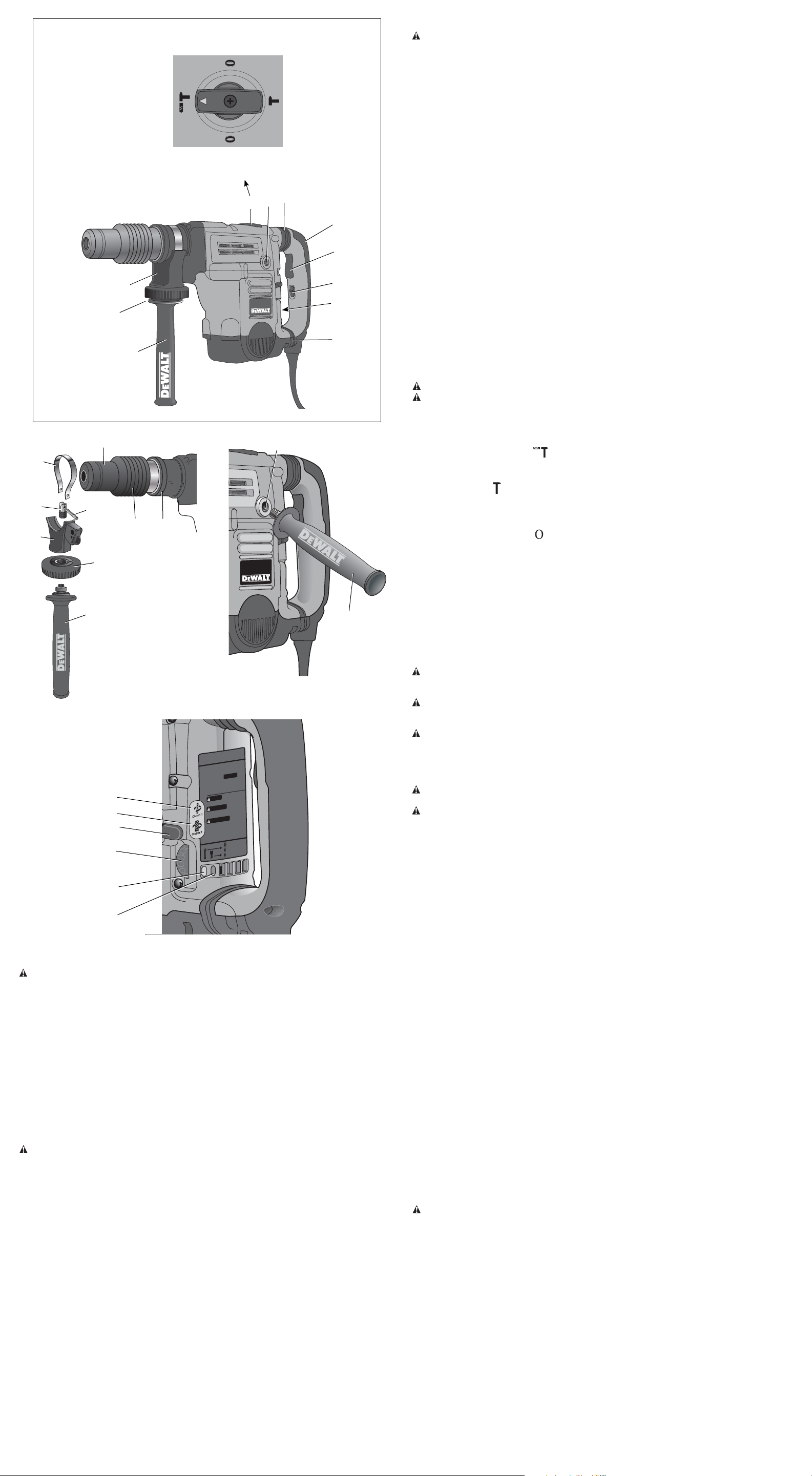
FIG. 1
HAMMERDRILLING MODE
MODE DE MARTEAU PERFORATEUR
MODO TALADRO PERCUTOR
CHISEL BIT ADJUSTMENT MODE
MODE DE RÉGLAGE DU TRÉPAN ORDINAIRE
MODO DE AJUSTE DE LA BROCA DE CINCEL
CHIPPING MODE
MODE DE BURINAGE
MODO CINCEL
CHISEL BIT ADJUSTMENT MODE
MODE DE RÉGLAGE DU TRÉPAN ORDINAIRE
MODO DE AJUSTE DE LA BROCA DE CINCEL
E
I
F
D
A
J
B
G
H
E
C
FIG. 2
M
FIG. 3
I
K
N
O
P
L
J
H
C
C
FIG. 4
COMPLETE TORQUE CONTROL
CTC
1 3/4" (44mm) SDS MAX
Y HAMMER
TAR
RO
D25XXX
SER.
Q
R
U
TO REDUCE THE RISK OF INJUR
WARNING
USER MUST READ INSTRUCTION
MANUAL. A
ATO
RESPIR
LEA EL MANUAL DE
ADVERTENCIA
INSTRUCCIONES PARA
UN FUNCIONAMIENTO SEGURO. SIEMPRE UTILICE
PROTECCIÓN ADECUADA
A
RESPIR
AFIN DE MINIMISER
VERTISSEMENT
A
LES RISQUES DE
BLESSURES,
D’UTILIS
OCULAIRE,
UTILISER LA POIGNÉE L
T INDUSTRIAL TOOL CO., BA
L
A
W
E
D
FOR SERVICE INFORMA
W
E
.D
w
ww
G
Y,
YS USE PROPER EYE, EAR AND
LWA
YS USE SIDE HANDLE.
A
LW
RY PROTECTION. A
PARA LOS OJOS, OÍDOS Y VÍAS
TORIAS. SIEMPRE UTILICE EL MANGO LATERAL.
TEUR DOIT LIRE LE GUIDE
A
’UTILIS
L
TE.
A
TOIRE ADÉQU
A
TION.TOUJOURS UTILISER UNE PROTECTION
A
AUDITIVE ET RESPIR
TÉRALE.
A
TIMORE, MD 21286 USA
L
T
L
A
W
E
TION, CALL 1-800-4-D
.com
T
L
A
Service
Lock-On
rvice
ush Se
r
B
S
T
COMPONENTS (Fig. 1)
WARNING: Never modify the power tool or any part of it. Damage or personal injury could
result.
A. Trigger switch F. Mode selector
B. Lock-on slider G. Electronic Speed and impact control dial
C. Side handle H. Clamp knob
D. Main handle I. Rear side handle position
E. Active vibration control
INTENDED USE
These heavy-duty rotary hammers have been designed for professional hammerdrilling and
chipping at various work sites (i.e., construction sites). DO NOT use under wet conditions or in
presence of flammable liquids or gases.
These heavy-duty rotary hammers are professional power tools. DO NOT let children come into
contact with the tool. Supervision is required when inexperienced operators use this tool.
ASSEMBLY AND ADJUSTMENTS
Side Handle (Fig. 1)
WARNING: To reduce the risk of personal injury, ALWAYS operate the tool with the side
handle properly installed and securely tightened. Failure to do so may result in the side handle
slipping during tool operation and subsequent loss of control. Hold tool with both hands to
maximize control.
The side handle clamps to the front barrel (collar) and may be rotated 360° to permit right
or left-hand use. For operating convenience, the side handle can be installed in front or rear
positions.
TO MOUNT IN FRONT POSITION (FIG. 3)
1. Unscrew the side handle (C) and disassemble the side handle clamp (J).
2. Snap the steel ring (K) over the collar (L) behind the tool holder (M). Squeeze both ends of
the steel ring together. Mount the bushing (N) and insert the pin (O).
3. Slide the side handle clamp (J) and bushing into the clamp knob (H) – do not tighten.
4. Screw the side handle (C) into the clamp knob (H) and tighten.
5. Rotate the side handle mounting assembly to the desired position. For hammerdrilling
horizontally with a heavy drill bit, place the side handle assembly at an angle of approximately
20° to the tool for optimum control.
6. Lock the side handle mounting assembly in place by tightening the clamp knob (H).
TO MOUNT IN REAR POSITION (FIG. 3)
1. Unscrew the side handle (C) and remove it from the side handle mounting assembly. Leave
the side handle mounting assembly in the front position.
2. Screw the side handle directly into one of the rear side handle positions (I) on either side of
the tool.
Active Vibration Control (Fig. 1)
For best vibration control, hold the tool with one hand on the main handle (D) and the other
hand on the side handle (C). Apply just enough pressure so the hammer is approximately midstroke. The hammer only needs enough pressure to engage the active vibration control. Applying
too much pressure will not make the tool drill or chip faster and active vibration control will not
engage.
Inserting and Removing SDS Max® Accessories (Fig. 3)
WARNING: To reduce the risk of serious personal injury, turn tool off and disconnect tool
from power source before making any adjustments or removing/installing attachments or
accessories.
1. Pull back the locking sleeve (P) and insert the bit shank. The bit shank must be clean and
slightly lubricated.
2. Turn the bit slightly until the sleeve snaps back into position.
3. Ensure the bit is properly engaged.
NOTE: The bit needs to move several centimeters in and out of the tool holder (M) when
properly engaged.
4. To remove the bit, pull back the locking sleeve and pull the bit out.
Complete Torque Control (Fig. 4)
NOTICE: Always turn the tool off before changing torque control settings or damage to tool may
result.
The Complete Torque Control (CTC) feature of this tool is designed to provide additional control
with a two-stage clutch mechanism.
Clutch Setting 1 (Q) is designed for most hammerdrilling applications and is designed to easily
clutch out when the drill bit encounters re-bar or other foreign substances.
Clutch Setting 2 (R) is designed for higher torque applications such as core-bits and deep hole
hammerdrilling and is designed to clutch out at a higher torque threshold.
Move the torque control lever (U) to setting 1 or 2 as needed for application.
NOTE: Allow the motor housing to rotate a little while changing torque.
Each time the tool is plugged in, it will automatically default to clutch setting 1, the most
sensitive setting.
Electronic Speed and Impact Control (Fig. 4)
The electronic speed and impact control allows the use of smaller drill bits without the risk of bit
breakage, hammerdrilling into light and brittle materials without shattering and optimal tool control for
precise chiseling.
To set the control dial, turn the dial (G) to the desired level. The higher the number, the greater
the speed and impact energy. Dial settings make the tool extremely flexible and adaptable
for many different appli cations. The required setting depends on the bit size and hardness of
material being drilled.
Mode Selector (Fig. 1)
CAUTION: Never change the mode while the unit is running.
CAUTION: Do not change to hammerdrill mode with chisel bit in tool holder. Personal injury
and damage to tool may result.
The D25712 an D25762 use two operating modes. To select the required operating mode, rotate
the mode selector (F) until the arrow points to the hammerdrilling or the chipping icon. The
D25831 and D25851 use only the chipping mode.
HAMMERDRILLING MODE (
)
The tool simultaneously rotates and impacts the work. This mode is appropriate for all concrete
and masonry operations.
CHIPPING MODE (
)
The spindle lock is engaged during chipping mode so the tool impacts the work without
rotating. This mode is appropriate for light chipping, chiseling and demolition applications.
NOTE: In chipping mode, the hammerdrill can also be used as a lever to free a jammed drill bit.
CHISEL BIT ADJUSTMENT ( )
Turn the mode selector to one of the chisel bit adjustment icons to adjust the chisel to the desired
position. There are 24 possible positions to set the angle of the chisel. After finding the desired
position, slightly maneuver the chisel bit back and forth to ensure the chisel is properly engaged.
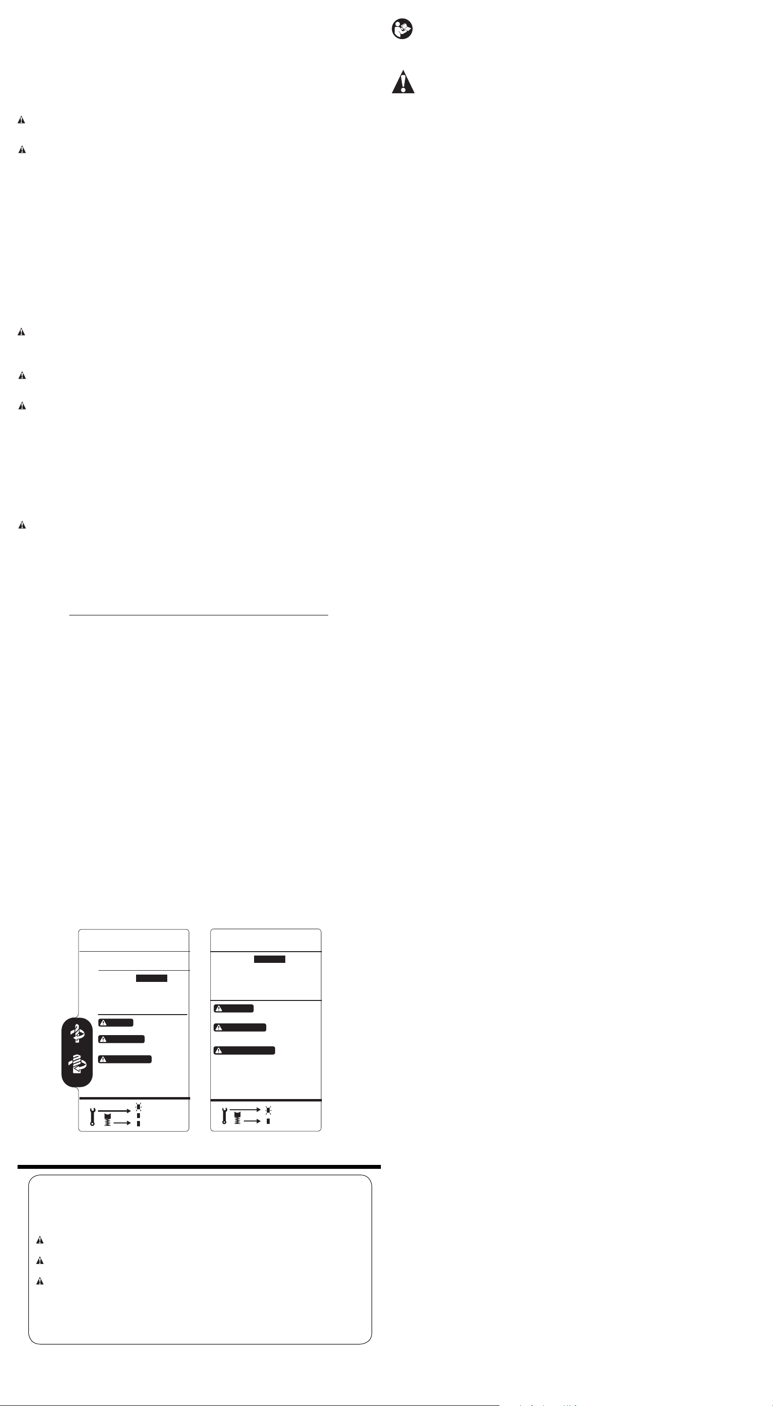
Power Indicator Lights (Fig. 4)
The yellow brushwear indicator LED (S) lights up when the carbon brushes are nearly worn out
indicating that the tool needs servicing within the next 8 hours of use.
The red indicator LED (T) lights up if the lock-on button (B) is used in any mode except the
chipping mode.
The red indicator LED (T) starts to flash if there is a fault with the tool or the brushes have
completely worn out (refer to Brushes under MAINTENANCE).
OPERATION
WARNING: To reduce the risk of serious personal injury, turn tool off and disconnect tool
from power source before making any adjustments or removing/installing attachments or
accessories.
WARNING: To reduce the risk of personal injury, ALWAYS ensure workpiece is anchored
or clamped firmly. If hammerdrilling thin material, use a wood “back-up” block to prevent
damage to the material.
WARNING: To reduce the risk of personal injury, ALWAYS operate the tool with the side
handle properly installed and securely tightened. Failure to do so may result in the side
handle slipping during tool operation and subsequent loss of control. Hold tool with both hands
to maximize control.
Proper Hand Position (Fig. 1)
WARNING: To reduce the risk of serious personal injury, ALWAYS use proper hand position
as shown.
WARNING: To reduce the risk of serious personal injury, ALWAYS hold securely in anticipation
of a sudden reaction.
Proper hand position requires one hand on the side handle (C), with the other hand on the main
handle (D).
NOTE: Operating temperature of this tool is 19˚ to 104˚ F (-7 to +40˚ C). Using the tool outside
of this temperature range will decrease the life of the tool.
Trigger Switch (Fig. 1)
To turn the tool on, depress the trigger switch (A). To stop the tool, release the trigger switch. To
lock the trigger switch on in the chipping mode only, push the lock-on slider (B) upwards while
depressing the trigger switch.
To deactivate the lock-on slider, depress the trigger switch once then release.
The lock-on slider may only be activated in chisel mode. The machine will stop running when
trying to engage the lock-on slider in drill mode. The motor will stop if the lock-on slider is
activated when changing from chisel mode into drill mode.
SOFT START FEATURE
The soft start feature allows you to build up speed slowly, thus preventing the drill bit from
walking off the intended hole position when starting. The soft start feature also reduces the
immediate torque reaction transmitted to the gearing and the operator if the hammer is started
with the drill bit in an existing hole.
Hammerdrilling with a Solid Bit
D25712, D25762
NOTE: The D25891 have only chipping modes with no hammerdrilling capability.
1. Set the mode selector to hammerdrilling mode.
2. Move the torque control lever to Setting 1 (Q).
3. Set the speed and impact control dial.
4. Insert the appropriate drill bit.
5. Adjust the side handle (front or rear position).
6. Mark the spot where the hole is to be drilled.
7. Place the drill bit on that mark and depress the trigger switch.
8. Apply only enough pressure to engage active vibration control (refer to Active Vibration
Control).
9. To stop the tool, release the trigger switch. Always turn the tool off when work is finished and
before unplugging.
Hammerdrilling with a Core Bit
D25712, D25762
CAUTION: Do not use a core bit for hammerdrilling wood. Personal injury and damage to tool
may result.
NOTE: The D25891 has only chipping mode with no hammerdrilling capability.
1. Set the mode selector to hammerdrilling mode.
2. Move the torque control lever to Setting 2 (R).
3. Turn the speed and impact control dial to the maximum torque position.
4. Adjust the side handle (front or rear position).
5. Assemble the centering bit and adapter shank into core bit.
6. Mark the spot where the hole is to be drilled.
7. Place the centering bit on that mark and depress the trigger switch.
NOTE: Some core drills require the removal of centering bit after about 1 cm of penetration. If
so, remove and continue hammerdrilling.
8. When hammerdrilling through a structure thicker than the depth of the core bit, break away
the round cylinder of concrete or core inside the bit at regular intervals. To avoid unwanted
breaking away of concrete around the hole, first drill a hole the diameter of the centering
bit completely through the structure. Then drill the cored hole halfway from each side of
the structure.
9. To stop the tool, release the trigger switch. Always turn the tool off when work is finished and
before unplugging.
Chipping and Chiseling
1. Set the mode selector to chipping mode.
2. Set the impact control dial to desired setting (refer to Electronic Speed and Impact
Control).
Page 3
3. Insert the appropriate chisel and rotate it by hand to lock it into the desired position.
NOTE: For SDS Max
®
models, only use SDS Max® insert tools.
4. Adjust the side handle (front or rear position).
5. Depress the trigger switch.
6. Apply only enough pressure to engage active vibration control (refer to Active Vibration
Control).
7. To stop the tool, release the trigger switch. Always turn the tool off when work is finished and
before unplugging.
Hammerdrilling (Fig. 1)
WARNING: To reduce the risk of serious personal injury, turn tool off and disconnect tool
from power source before making any adjustments or removing/installing attachments or
accessories.
WARNING: To reduce the risk of personal injury, ALWAYS ensure workpiece is anchored
or clamped firmly. If hammerdrilling thin material, use a wood “back-up” block to prevent damage
to the material.
Press mode selector button and turn the mode selector (F) to the drill bit symbol for hammerdrilling,
to the hammer symbol for hammering or to the hammerdrill symbol for hammerdrilling.
HAMMERDRILL OPERATION
1. When hammerdrilling, use just enough force on the hammer to keep it from bouncing
excessively or “rising” off the bit. Too much force will cause slower hammerdrilling speeds,
overheating, and a lower hammerdrilling rate.
2. Drill straight, keeping the bit at a right angle to the work. Do not exert side pressure on the bit
when hammerdrilling as this will cause clogging of the bit flutes and a slower hammerdrilling
speed.
3. When hammerdrilling deep holes, if the hammer speed starts to drop off, pull the bit partially
out of the hole with the tool still running to help clear debris from the hole.
4. For masonry, use carbide-tipped bits or masonry bits. A smooth even flow of dust indicates
the proper hammerdrilling rate.
MAINTENANCE
WARNING: To reduce the risk of serious personal injury, turn tool off and disconnect tool
from power source before making any adjustments or removing/installing attachments or
accessories.
Cleaning
WARNING: Blow dirt and dust out of all air vents with dry air at least once a week. Wear
proper ANSI Z87.1 (CAN/CSA Z94.3) eye protection and proper NIOSH/OSHA/MSHA
respiratory protection when performing this.
WARNING: Never use solvents or other harsh chemicals for cleaning the non-metallic parts
of the tool. These chemicals may weaken the plastic materials used in these parts. Use a cloth
dampened only with water and mild soap. Never let any liquid get inside the tool; never immerse
any part of the tool into a liquid.
Lubrication
Your tool was properly lubricated before leaving the factory. In from two to six months, depending
upon use, take or send your tool to an authorized service center for a complete cleaning,
inspection and lubrication. Tools used constantly on production jobs will need relubrication more
often. Also, tools “out of service” for long periods should be relubricated before being put back
to work.
Accessories
WARNING: Since accessories, other than those offered by DEWALT, have not been tested
with this product, use of such accessories with this tool could be hazardous. To reduce the risk
of injury, only D
EWALT, recommended accessories should be used with this product.
Recommended accessories for use with your tool are available at extra cost from your local
dealer or authorized service center. If you need assistance in locating any accessory, please
contact D
EWALT Industrial Tool Co., 701 East Joppa Road, Baltimore, MD 21286, call
1-800-4-DEWALT (1-800-433-9258) or visit our website www.dewalt.com.
MAXIMUM CAPACITY
D25712 D25762 D25891
Concrete > 2" (51 mm) 2" (52 mm) –
RPM 137–275 125–250 –
No load BPM 1260–2520 1150–2300 1150–2300
Repairs
To assure product SAFETY and RELIABILITY, repairs, maintenance and adjustments (including
brush inspection and replacement) should be performed by a D
EWALT authorized service center or other qualified service personnel. Always use identical
a D
replacement parts.
EWALT factory service center,
Three Year Limited Warranty
DEWALT will repair, without charge, any defects due to faulty materials or workmanship for
three years from the date of purchase. This warranty does not cover part failure due to normal
wear or tool abuse. For further detail of warranty coverage and warranty repair information, visit
www.dewalt.com or call 1-800-4-D
EWALT (1-800-433-9258). This warranty does not apply to
accessories or damage caused where repairs have been made or attempted by others. This
warranty gives you specific legal rights and you may have other rights which vary in certain
states or provinces.
In addition to the warranty, D
EWALT tools are covered by our:
2 YEARS FREE SERVICE
D
EWALT will maintain the tool and replace worn parts caused by normal use, for free, any time
during the first two years after purchase.
90 DAY MONEY BACK GUARANTEE
If you are not completely satisfied with the performance of your D
EWALT Power Tool, Laser, or
Nailer for any reason, you can return it within 90 days from the date of purchase with a receipt
for a full refund – no questions asked.
LATIN AMERICA: This warranty does not apply to products sold in Latin America. For products
sold in Latin America, see country specific warranty information contained either in the
packaging, call the local company or see website for warranty information.
FREE WARNING LABEL REPLACEMENT: If your warning labels become illegible or are
missing, call 1-800-4-D
Clutch 1
Clutch 2
EWALT for a free replacement.
CTC
COMPLETE TORQUE CONTROL
D25XXX
SER.
TO REDUCE THE RISK OF INJURY,
WARNING
USER MUST READ INSTRUCTION
MANUAL. ALWAYS USE PROPER EYE, EAR AND
RESPIRATORY PROTECTION. ALWAYS USE SIDE HANDLE.
LEA EL MANUAL DE
ADVERTENCIA
INSTRUCCIONES PARA
UN FUNCIONAMIENTO SEGURO. SIEMPRE UTILICE
PROTECCIÓN ADECUADA PARA LOS OJOS, OÍDOS Y VÍAS
RESPIRATORIAS. SIEMPRE UTILICE EL MANGO LATERAL.
AFIN DE MINIMISER
AVERTISSEMENT
LES RISQUES DE
BLESSURES, L’UTILISATEUR DOIT LIRE LE GUIDE
D’UTILISATION.TOUJOURS UTILISER UNE PROTECTION
OCULAIRE, AUDITIVE ET RESPIRATOIRE ADÉQUATE.
UTILISER LA POIGNÉE LATÉRALE.
DEWALT INDUSTRIAL TOOL CO., BALTIMORE, MD 21286 USA
FOR SERVICE INFORMATION, CALL 1-800-4-DEWALT
www.DEWALT.com
Service
Lock-On
Brush Service
TM
SDS MAX
D25891
SER.
TO REDUCE THE RISK OF INJURY,
WARNING
USER MUST READ INSTRUCTION
MANUAL. ALWAYS USE PROPER EYE, EAR AND
RESPIRATORY PROTECTION. ALWAYS USE SIDE HANDLE.
LEA EL MANUAL DE
ADVERTENCIA
INSTRUCCIONES PARA UN
FUNCIONAMIENTO SEGURO. SIEMPRE UTILICE
PROTECCIÓN ADECUADA PARA LOS OJOS, OÍDOS Y VÍAS
RESPIRATORIAS. SIEMPRE UTILICE EL MANGO LATERAL.
AFIN DE MINIMISER
AVERTISSEMENT
LES RISQUES DE
BLESSURES, L’UTILISATEUR DOIT LIRE LE GUIDE
D’UTILISATION.TOUJOURS UTILISER UNE PROTECTION
OCULAIRE, AUDITIVE ET RESPIRATOIRE ADÉQUATE.
UTILISER LA POIGNÉE LATÉRALE.
DEWALT INDUSTRIAL TOOL CO., BALTIMORE, MD 21286 USA
FOR SERVICE INFORMATION, CALL 1-800-4-D
www. DEWALT.com
CHIPPING HAMMER
EWALT
Service
Brush Service
Définitions : lignes directrices en
matière de sécurité
Les définitions ci-dessous décrivent le niveau de danger pour chaque mot-indicateur
employé. Veuillez lire le mode d’emploi et porter une attention particulière à ces
symboles.
DANGER : indique une situation dangereuse imminente qui, si elle n’est pas
évitée, causera la mort ou des blessures graves.
AVERTISSEMENT : indique une situation potentiellement dangereuse qui, si elle
n’est pas évitée, pourrait se solder par un décès ou des blessures graves.
ATTENTION : indique une situation potentiellement dangereuse
qui, si elle n’est pas évitée pourrait se solder par des blessures mineures ou
modérées.
AVIS : indique une pratique ne posant aucun risque de dommages corporels mais
qui par contre, si rien n’est fait pour l’éviter, pourrait poser des risques de dommages
matériels.
POUR TOUTE QUESTION OU TOUT COMMENTAIRE RELATIF À CET OUTIL OU À
PROPOS DE TOUT AUTRE OUTIL D
(1-800-433-9258).
EWALT, COMPOSER SANS FRAIS LE : 1-800-4-DEWALT
AVERTISSEMENT : afin de réduire le risque de blessures, lire le mode d’emploi de l’outil.
Avertissements de sécurité généraux pour les outils
électriques
AVERTISSEMENT! Lire tous les avertissements de sécurité et les directives. Le
non-respect des avertissements et des directives pourrait se solder par un choc
électrique, un incendie et/ou une blessure grave.
CONSERVER TOUS LES AVERTISSEMENTS ET TOUTES
LES DIRECTIVES POUR UN USAGE ULTÉRIEUR
Le terme « outil électrique » cité dans les avertissements se rapporte à votre outil électrique à
alimentation sur secteur (avec fil) ou par piles (sans fil).
1) SÉCURITÉ DU LIEU DE TRAVAIL
a) Tenir l’aire de travail propre et bien éclairée. Les lieux encombrés ou sombres sont
propices aux accidents.
b) Ne pas faire fonctionner d’outils électriques dans un milieu déflagrant, tel qu’en
présence de liquides, de gaz ou de poussières inflammables. Les outils électriques
produisent des étincelles qui pourraient enflammer la poussière ou les vapeurs.
c) Éloigner les enfants et les personnes à proximité pendant l’utilisation d’un outil
électrique. Une distraction pourrait en faire perdre la maîtrise à l’utilisateur.
2) SÉCURITÉ EN MATIÈRE D’ÉLECTRICITÉ
a) Les fiches des outils électriques doivent correspondre à la prise. Ne jamais modifier
la fiche d’aucune façon. Ne jamais utiliser de fiche d’adaptation avec un outil
électrique mis à la terre. Le risque de choc électrique sera réduit par l’utilisation de fiches
non modifiées correspondant à la prise.
b) Éviter tout contact physique avec des surfaces mises à la terre comme des tuyaux,
des radiateurs, des cuisinières et des réfrigérateurs. Le risque de choc électrique est
plus élevé si votre corps est mis à la terre.
c) Ne pas exposer les outils électriques à la pluie ou à l’humidité. La pénétration de l’eau
dans un outil électrique augmente le risque de choc électrique.
d) Ne pas utiliser le cordon de façon abusive. Ne jamais utiliser le cordon pour
transporter, tirer ou débrancher un outil électrique. Tenir le cordon éloigné de
la chaleur, de l’huile, des bords tranchants et des pièces mobiles. Les cordons
endommagés ou enchevêtrés augmentent les risques de choc électrique.
e) Pour l’utilisation d’un outil électrique à l’extérieur, se servir d’une rallonge convenant
à cette application. L’utilisation d’une rallonge conçue pour l’extérieur réduira les risques
de choc électrique.
f) S’il est impossible d’éviter l’utilisation d’un outil électrique dans un endroit humide,
brancher l’outil dans une prise ou sur un circuit d’alimentation dotés d’un disjoncteur de
fuite à la terre (GFCI). L’utilisation de ce type de disjoncteur réduit les risques de choc
électrique.
3) SÉCURITÉ PERSONNELLE
a) Être vigilant, surveiller le travail effectué et faire preuve de jugement lorsqu’un outil
électrique est utilisé. Ne pas utiliser d’outil électrique en cas de fatigue ou sous
l’influence de drogues, d’alcool ou de médicaments. Un simple moment d’inattention
en utilisant un outil électrique peut entraîner des blessures corporelles graves.
b) Utiliser des équipements de protection individuelle. Toujours porter une protection
oculaire. L’utilisation d’équipements de protection comme un masque antipoussière, des
chaussures antidérapantes, un casque de sécurité ou des protecteurs auditifs lorsque la
situation le requiert réduira les risques de blessures corporelles.
c) Empêcher les démarrages intempestifs. S’assurer que l’interrupteur se trouve à la
position d’arrêt avant de relier l’outil à une source d’alimentation et/ou d’insérer un
bloc-piles, de ramasser ou de transporter l’outil. Transporter un outil électrique alors
que le doigt repose sur l’interrupteur ou brancher un outil électrique dont l’interrupteur est
à la position de marche risque de provoquer un accident.
d) Retirer toute clé de réglage ou clé avant de démarrer l’outil. Une clé ou une clé de
réglage attachée à une partie pivotante de l’outil électrique peut provoquer des blessures
corporelles.
e) Ne pas trop tendre les bras. Conserver son équilibre en tout temps. Cela permet de
mieux maîtriser l’outil électrique dans les situations imprévues.
f) S’habiller de manière appropriée. Ne pas porter de vêtements amples ni de bijoux.
Garder les cheveux, les vêtements et les gants à l’écart des pièces mobiles. Les
vêtements amples, les bijoux ou les cheveux longs risquent de rester coincés dans les
pièces mobiles.
g) Si des composants sont fournis pour le raccordement de dispositifs de dépoussiérage
et de ramassage, s’assurer que ceux-ci sont bien raccordés et utilisés. L’utilisation
d’un dispositif de dépoussiérage peut réduire les dangers engendrés par les poussières.
4) UTILISATION ET ENTRETIEN D’UN OUTIL ÉLECTRIQUE
a) Ne pas forcer un outil électrique. Utiliser l’outil électrique approprié à l’application.
L’outil électrique approprié effectuera un meilleur travail, de façon plus sûre et à la vitesse
pour laquelle il a été conçu.
b) Ne pas utiliser un outil électrique dont l’interrupteur est défectueux. Tout outil
électrique dont l’interrupteur est défectueux est dangereux et doit être réparé.
c) Débrancher la fiche de la source d’alimentation et/ou du bloc-piles de l’outil
électrique avant de faire tout réglage ou changement d’accessoire ou avant de
ranger l’outil. Ces mesures préventives réduisent les risques de démarrage accidentel de
l’outil électrique.
d) Ranger les outils électriques hors de la portée des enfants et ne permettre à
aucune personne n’étant pas familière avec un outil électrique ou son mode
d’emploi d’utiliser cet outil. Les outils électriques deviennent dangereux entre les mains
d’utilisateurs inexpérimentés.
e) Entretien des outils électriques. Vérifier si les pièces mobiles sont mal alignées ou
coincées, si des pièces sont brisées ou présentent toute autre condition susceptible
de nuire au bon fonctionnement de l’outil électrique. En cas de dommage, faire
réparer l’outil électrique avant toute nouvelle utilisation. Beaucoup d’accidents sont
causés par des outils électriques mal entretenus.
f) S’assurer que les outils de coupe sont aiguisés et propres. Les outils de coupe
bien entretenus et affûtés sont moins susceptibles de se coincer et sont plus faciles à
maîtriser.
g) Utiliser l’outil électrique, les accessoires, les forets, etc. conformément aux
présentes directives en tenant compte des conditions de travail et du travail à
effectuer. L’utilisation d’un outil électrique pour toute opération autre que celle pour laquelle
il a été conçu est dangereuse.
5) RÉPARATION
a) Faire réparer l’outil électrique par un réparateur professionnel en n’utilisant que des
pièces de rechange identiques. Cela permettra de maintenir une utilisation sécuritaire
de l’outil électrique.
Consignes de sécurité additionnelles propres aux
marteaux rotatifs
• Porter un dispositif de protection auditif. Le bruit en résultant pourrait occasionner une
perte de l’acuité auditive.
• Utiliser la/les poignée(s) auxiliaire(s) si fournie(s) avec l’outil. Une perte de contrôle de
l’outil pourrait occasionner des dommages corporels.
• Tenir l’outil par les surfaces isolées prévues à cet effet pendant toute utilisation où
l’organe de coupe pourrait entrer en contact avec des fils électriques cachés ou
son propre cordon. Tout contact de l’organe de coupe avec un fil sous tension mettra les
parties métalliques exposées de l’outil sous tension et électrocutera l’utilisateur.
• Utiliser des serre-joints, ou tout autre moyen, pour fixer et immobiliser le matériau
sur une surface stable. Tenir la pièce à la main ou contre son corps offre une stabilité
insuffisante qui pourrait vous en faire perdre le contrôle.
• Porter des lunettes de protection ou toute autre protection oculaire. Le martelage
pourrait faire voltiger des éclats. Ces particules volantes pourraient occasionner des
dommages oculaires permanents. Porter un masque anti-poussières ou un appareil de
protection des voies respiratoires pour toute application productrice de poussières. Une
protection auditive peut s’avérer nécessaire pour la plupart des applications.
• Maintenir systématiquement l’outil fermement. Ne pas tenter d’utiliser cet outil sans
le maintenir à deux mains. Il est recommandé d’utiliser systématiquement la poignée
latérale. Le fait d’utiliser cet outil à une main pourra vous en faire perdre le contrôle. Traverser
ou rencontrer des matériaux durs comme les armatures peut aussi s’avérer dangereux.
Resserrer soigneusement la poignée latérale avant toute utilisation.
• Ne pas utiliser cet outil pendant des périodes de temps prolongées. Les vibrations
causées par la percussion peuvent poser des risques pour les mains ou les bras. Porter des
gants pour amortir les vibrations, et pour limiter les risques, faire des pauses fréquentes.
• Ne pas remettre à neuf les forets soi-même. La remise à neuf de tout burin doit être
effectuée par un spécialiste agréé. Tout burin remis à neuf incorrectement pose des risques
de dommages corporels.
• Porter des gants lors de l’utilisation de l’outil ou le changement de mèche. Les parties
métalliques accessibles de l’outil et des mèches/forets pourraient s’avérer brûlantes lors de
l’utilisation. De petits débris de matériau pourraient aussi blesser les mains nues.
• Attendre systématiquement l’arrêt complet de la mèche/foret avant de déposer l’outil
où que ce soit. Des forets/mèches en rotation posent des risques de dommages corporels.
• Ne pas donner des coups de marteau sur des forets/mèches coincés pour les déloger.
Des fragments de métal ou de matériau pourraient être éjectés et causer des dommages
corporels.
Page 4

• Les burins légèrement usés peuvent être réaffutés.
.....................
REMARQUE : ne pas surchauffer une mèche (jusqu’à sa décoloration) pendant le
réaffutage. Les burins très émoussés doivent être remartelés. Ne pas retremper un burin ou
en faire un revenu.
• Maintenir le cordon d’alimentation à l’écart d’une mèche en rotation. Ne pas enrouler
le cordon autour d’une partie quelconque de votre corps. Un cordon électrique enroulé
autour d’une mèche en rotation pose des risques de dommages corporels et de perdre le
contrôle de l’outil.
• Prendre des précautions à proximité des évents, car ils cachent des pièces mobiles.
Vêtements amples, bijoux ou cheveux longs risquent de rester coincés dans ces pièces
mobiles.
• Pour la sécurité de l’utilisateur, utiliser une rallonge de calibre adéquat (AWG,
American Wire Gauge [calibrage américain normalisé des fils électriques]). Plus
le calibre est petit, et plus sa capacité est grande. Un calibre 16, par exemple, a plus de
capacité qu’un calibre 18. L’usage d’une rallonge de calibre insuffisant causera une chute de
tension entraînant perte de puissance et surchauffe. Si plusieurs rallonges sont nécessaires
pour obtenir une certaine longueur, s’assurer que chaque rallonge présente au moins le
calibre de fil minimum. Le tableau ci-dessous illustre les calibres à utiliser selon la longueur
de rallonge et l’intensité nominale indiquée sur la plaque signalétique. En cas de doute,
utiliser le calibre suivant. Plus le calibre est petit, plus la rallonge peut supporter de courant.
Calibres minimaux des rallonges
Volts Longueur totale de cordon en mètres (pieds)
Intensité (en ampères)
Plus de Pas plus de AWG
0 6 18 16 16 14
610 18161412
10 12 16 16 14 12
12 16 14 12 Non recommandé
AVERTISSEMENT : Porter SYSTÉMATIQUEMENT des lunettes de protection. Les lunettes
courantes NE sont PAS des lunettes de protection. Utiliser aussi un masque antipoussières si
la découpe doit en produire beaucoup. PORTER SYSTÉMATIQUEMENT UN ÉQUIPEMENT
DE SÉCURITÉ HOMOLOGUÉ :
• Protection oculaire ANSI Z87.1 (CAN/CSA Z94.3 ;
• Protection auditive ANSI S12.6 (S3.19) ;
• Protection des voies respiratoires NIOSH/OSHA/MSHA.
AVERTISSEMENT : Les scies, meules, ponceuses, perceuses ou autres outils de
construction peuvent produire des poussières contenant des produits chimiques reconnus pour
causer cancers, malformations congénitales ou être nocifs au système reproducteur. Parmi ces
produits chimiques, on retrouve :
• le plomb dans les peintures à base de plomb ;
• la silice cristallisée dans les briques et le ciment ou autres articles de maçonnerie ; et
• l’arsenic et le chrome dans le bois ayant subi un traitement chimique.
Le risque associé à de telles expositions varie selon la fréquence à laquelle on effectue ces
travaux. Pour réduire toute exposition à ces produits : travailler dans un endroit bien aéré, en
utilisant du matériel de sécurité homologué tel un masque antipoussières spécialement conçu
pour filtrer les particules microscopiques.
• Limiter tout contact prolongé avec les poussières provenant du ponçage, sciage,
meulage, perçage ou toute autre activité de construction. Porter des vêtements de
protection et nettoyer à l’eau savonneuse les parties du corps exposées. Le fait de
laisser la poussière pénétrer dans la bouche, les yeux ou la peau peut provoquer l’absorption
de produits chimiques dangereux.
AVERTISSEMENT : Cet outil peut produire et/ou répandre de la poussière susceptible de
causer des dommages sérieux et permanents au système respiratoire. Toujours utiliser un
appareil respiratoire antipoussières homologué par le NIOSH ou l’OSHA. Diriger les particules
dans le sens opposé au visage et au corps.
AVERTISSEMENT : Porter systématiquement une protection oculaire. Tout utilisateur ou
individu présent doit porter une protection oculaire homologuée ANSI Z87.1.
AVERTISSEMENT : Pendant l’utilisation, porter systématiquement une protection
auditive individuelle adéquate homologuée ANSI S12.6 (S3.19). Sous certaines conditions
et suivant la longueur d’utilisation, le bruit émanant de ce produit pourrait contribuer à une perte
de l’acuité auditive.
• L’étiquette apposée sur votre outil peut inclure les symboles suivants. Les symboles et leur
définition sont définis ci-après :
V ...................volts A .................... ampères
Hz .................hertz W ................... watts
min ............... minutes
............ courant continu ................. courant alternatif ou continu
.................Classe / Fabrication
..................... (mis à la terre) ..................borne de terre
.................Classe II Fabrication .................. symbole d’avertissement
..................... (double isolation) BPM ..............battements par minute
…/min ..........par minute R/MIN ............ tours par minute
120V
240V
7,6 (25) 15,2 (50) 30,5 (100) 45,7 (150)
15,2 (50) 30,5 (100) 61,0 (200) 91,4 (300)
................. courant alter natif
n
o .................. vitesse à vide
Moteur
Votre outil DEWALT est équipé d’un moteur d’origine DEWALT. S’assurer que le courant utilisé
correspond bien à celui indiqué sur la plaque signalétique. Une baisse de tension de plus de
10% causera perte de puissance et surchauffe. Tous les outils D
EWALT sont testés en usine.
DESCRIPTION (Fig. 1)
AVERTISSEMENT : Ne jamais modifier l’outil électrique ni aucun de ses composants. Il y a
risques de dommages corporels ou matériels.
A. Gâchette F. Sélecteur de mode
B. Glissière de verrouillage G. Régulateur électronique de vitesse et d’impact
C. Poignée latérale H. Bouton de fixation
D. Poignée principale I. Position arrière de la poignée latérale
E. Système d’amortissement des vibrations
USAGE PRÉVU
Ces marteaux rotatifs industriels ont été conçus pour le martelage-perforage et le burinage
professionnels sur des chantiers divers (ex. : chantiers de construction). NE PAS les utiliser en
milieu ambiant humide ou en présence de liquides ou de gaz inflammables.
Ces marteaux rotatifs industriels sont des outils de professionnels. NE PAS les laisser à la
portée des enfants. Une supervision est nécessaire auprès de tout utilisateur non expérimenté.
ASSEMBLAGE ET RÉGLAGES
Poignée latérale (Fig. 1)
AVERTISSEMENT : pour réduire tout risque de dommages corporels, utiliser
SYSTÉMATIQUEMENT l’outil avec sa poignée latérale installée correctement et solidement
arrimée. Tout manquement à cette directive pourrait faire que la poignée latérale glisse pendant
l’utilisation de l’outil et entraîner la perte du contrôle de celui-ci. Maintenir l’outil fermement à
deux mains pour un contrôle optimal.
La poignée latérale se fixe sur le barillet avant (collier) et peut effectuer une rotation de 360 °
pour permettre d’être utilisée par un gaucher ou un droitier. Pour faciliter l’utilisation, la poignée
latérale peut être installée sur la position avant ou arrière.
INSTALLATION EN POSITION AVANT (FIG. 3)
1. Dévissez la poignée latérale (C) et démontez le dispositif de fixation de la poignée latérale
(J).
2. Enclenchez la bague d’acier (K) sur le collier (L) derrière le porte-outil (M). Appuyez en
même temps sur les deux extrémités de la bague d’acier. Installez la bague (N) puis insérez
la goupille (O).
3. Repoussez le dispositif de fixation de la poignée latérale (J) et l’anneau sur le bouton de
fixation (H) (ne pas resserrer).
4. Vissez la poignée latérale (C) sur le bouton de fixation (H) puis serrez à fond.
5. Faites tourner le dispositif de la poignée latérale sur la position désirée. Pour le martelageperforage horizontal avec un foret épais, placez le dispositif de la poignée latérale à un
angle approximatif de 20 ° de l’outil pour optimiser le contrôle de ce dernier.
6. Verrouillez le dispositif de fixation de la poignée latérale en place en resserrant le bouton de
fixation (H).
INSTALLATION EN POSITION ARRIÈRE (FIG. 3)
1. Dévissez la poignée latérale (C) et retirez-la du dispositif de fixation de la poignée latérale.
Laissez le dispositif de la poignée latérale sur la position désirée.
2. Vissez directement la poignée latérale sur l’une de ses positions arrière (I) d’un côté ou de
l’autre de l’outil.
Système d’amortissement des vibrations (Fig. 1)
Pour optimiser le contrôle des vibrations, maintenez l’outil une main sur la poignée principale
(D) et l’autre sur la poignée latérale (C). Appliquez juste assez de pression sur le marteau
de façon à ce qu’il tourne à mi-régime. Seule une quantité limitée de pression sur le marteau
est nécessaire pour activer le système d’amortissement. Appliquer une pression excessive
sur l’outil ne le fera ni percer ni buriner plus rapidement et préviendra l’activation du système
d’amortissement.
Installation et retrait des accessoires SDS Max® (Fig. 3)
AVERTISSEMENT : pour réduire tout risque de dommages corporels graves, arrêter et
débrancher l’outil avant tout réglage ou avant de retirer ou installer toute pièce ou tout
accessoire.
1. Tirez vers l’arrière le manchon de verrouillage (P) et insérez une tige de mèche. La tige de
mèche doit être propre et légèrement lubrifiée.
2. Tournez la mèche légèrement jusqu’à ce que le manchon s’enclenche en position.
3. Assurez-vous que la mèche est correctement arrimée.
REMARQUE : la mèche doit pouvoir bouger de quelques centimètres, vers l’avant ou
l’arrière, dans le porte-outil (M) pour être correctement installée.
4. Pour retirer la mèche, tirez le manchon de verrouillage vers l’arrière et sortez la mèche.
Correcteur de couple intégral (Fig. 4)
AVIS : arrêter systématiquement l’outil avant de changer les paramètres de couples pour éviter
d’endommager l’outil.
La fonctionnalité de correcteur de couple intégral (CCI) de cet outil a été conçue pour permettre
d’optimiser le contrôle grâce à un mécanisme d’embrayage à deux phases.
Le réglage de couple 1 (Q) a été conçu pour la plupart des applications de martelage-perforage
et pour débrayer facilement lorsque la mèche rencontrera une armature ou tout autre matériel
étranger.
Le réglage de couple 2 (R) a été prévu pour des applications nécessitant un couple élevé
comme le perçage à percussion avec trépans carottiers ou mèches demi-rondes et conçu pour
débrayer à un seuil plus élevé de couple.
Déplacez le levier du régulateur de couple (U) sur les réglages 1 ou 2 en fonction de l’application.
REMARQUE : laisser le boîtier du moteur tourner un peu avant de changer le couple.
Chaque fois que l’outil sera branché, il retournera automatiquement par défaut sur le réglage
d’embrayage 1, le réglage le plus sensible.
Régulateur électronique de vitesse et d’impact (Fig. 4)
Le régulateur électronique de vitesse et d’impact permet l’utilisation de mèches plus petites
sans risquer de les briser, le perçage à percussion de matériaux légers ou fragiles sans les faire
éclater, et l’optimisation du contrôle de l’outil pour le ciselage de précision.
Pour l’ajuster, tournez le régulateur (G) sur le niveau désiré. Plus le chiffre est élevé, plus
la vitesse et l’énergie d’impact seront grandes. Les paramètres du régulateur rendent l’outil
extrêmement flexible et adaptable à différentes applications. Le réglage requis dépendra de la
taille de la mèche et de la dureté du matériau à percer.
Sélecteur de mode (Fig. 1)
ATTENTION : ne jamais changer de mode alors que l’appareil tourne.
ATTENTION : ne pas passer au mode martelage-perforage avec un foret dans le porte-outil
pour prévenir tout risque de dommages corporels ou matériels.
Les modèles D25712 et D25762 possèdent deux modes d’opérations. Pour choisir le mode
d’utilisation requis, tournez le sélecteur de mode (F) jusqu’à ce que la flèche pointe sur l’icône
martelage-perforage ou burinage. Les modèles D25831 et D25851 ne possèdent que le mode
burinage.
MODE MARTELAGE-PERFORAGE (
L’outil tourne et percute simultanément la pièce à travailler. Ce mode est approprié pour travailler
le béton et la maçonnerie.
MODE BURINAGE (
Le verrou de la broche est activé en mode burinage de façon à permettre la percussion sans
rotation. Ce mode est approprié pour la démolition, le burinage et le ciselage légers.
REMARQUE : en mode burinage, le marteau-perforateur peut aussi être utilisé comme levier
pour débloquer une mèche enrayée.
RÉGLAGE DU FORET (
Tournez le sélecteur de mode sur l’une des icônes de réglage de foret pour l’ajuster sur la
position désirée. Le burin peut être réglé sur 24 positions d’angles. Une fois la position désirée
choisie, déplacez légèrement d’avant en arrière le foret pour vous assurer qu’il est correctement
engagé.
)
)
)
Voyants d’alimentation (Fig. 4)
Le voyant DEL jaune (S) d’usure des balais s’allumera lorsque les balais de charbon seront
presque usés pour indiquer que la maintenance de l’outil devrait être effectuée dans les 8 heures
d’utilisation.
Le voyant DEL rouge (T) s’allumera lorsque le bouton de verrouillage en position de marche (B)
sera activé dans tous les modes, excepté celui de burinage.
Le voyant DEL rouge (T) clignotera en cas de problème avec l’outil ou si les balais sont
complètement usés (se reporter à la section Balais sous MAINTENANCE).
FONCTIONNEMENT
AVERTISSEMENT : Pour réduire tout risque de dommages corporels graves, arrêter et
débrancher l’outil avant tout réglage ou avant de retirer ou installer toute pièce ou tout
accessoire.
AVERTISSEMENT : pour réduire tout risque de dommages corporels, s’assurer
SYSTÉMATIQUEMENT que la pièce est ancrée ou arrimée solidement. Pour le martelage-
perforage de matériaux fins, utiliser un morceau de bois « de renfort » pour éviter de les
endommager.
AVERTISSEMENT : Pour réduire tout risque de dommages corporels, utiliser
SYSTÉMATIQUEMENT l’outil avec sa poignée latérale installée correctement et solidement
arrimée. Tout manquement à cette directive pourrait faire que la poignée latérale glisse pendant
l’utilisation de l’outil et entraîner la perte du contrôle de celui-ci. Maintenir l’outil fermement à
deux mains pour un contrôle maximum.
Position correcte des mains (Fig. 1)
AVERTISSEMENT : Pour réduire tout risque de dommages corporels graves, adopter
SYSTÉMATIQUEMENT la position des mains illustrée.
AVERTISSEMENT : Pour réduire tout risque de dommages corporels graves, Maintenir
SYSTÉMATIQUEMENT l’outil fermement pour anticiper toute réaction soudaine.
La position correcte des mains requiert une main sur la poignée latérale (C), et l’autre sur la
poignée principale (D).
REMARQUE : il est recommandé d’utiliser cet outil à des températures entre -7 ˚ et +40 ˚C (19 ˚
et 104 ˚F). L’utilisation de cet outil en dehors de ces températures en réduira la durée de vie.
Gâchette (Fig. 1)
Pour mettre l’outil en marche, appuyez sur la gâchette (A). Pour arrêter l’outil, relâchez la
gâchette. Pour verrouiller la gâchette sur le mode burinage seulement, poussez la glissière de
verrouillage (B) vers le haut tout en appuyant sur la gâchette.
Pour désactiver la glissière de verrouillage, réappuyez rapidement une fois sur la gâchette.
La glissière de verrouillage ne peut être activée qu’en mode ciselage. L’appareil s’arrêtera
de fonctionner si on tente d’activer la glissière de verrouillage en mode perçage. Le moteur
s’arrêtera de tourner si la glissière de verrouillage est activée pour passer du mode ciselage au
mode perçage.
FONCTION DÉMARRAGE EN DOUCEUR
La fonction démarrage en douceur permet d’accroître la vitesse progressivement, pour prévenir
que la mèche quitte la position désirée pour le trou au démarrage. La fonction démarrage
en douceur réduit aussi la transmission immédiate de retour de couple à l’engrenage et à
l’utilisateur si le marteau venait à démarrer alors que la mèche est dans un trou existant.
Martelage à percussion avec un trépan plein
D25712, D25762
REMARQUE : le modèle D25891 ne possède que le mode burinage et pas de martelage-
perforage.
1. Réglez le sélecteur de mode sur le mode martelage-perforage.
2. Ajustez le levier du régulateur de couple sur le réglage 1 (Q).
3. Réglez le régulateur électronique de vitesse et d’impact.
4. Insérez la mèche appropriée.
5. Ajustez la poignée latérale (position arrière ou avant).
6. Marquez l’endroit où le trou doit être percé.
7. Placez la mèche sur le tracé et appuyez sur la gâchette.
8. Appliquez seulement une quantité limitée de pression sur le marteau pour activer le système
d’amortissement (se reporter à la section Système d’amortissement des vibrations).
9. Pour arrêter l’outil, relâchez la gâchette. Mettez systématiquement l’interrupteur en position
d’arrêt une fois le travail terminé et avant de débrancher l’outil.
Perçage à percussion avec un trépan carottier
D25712, D25762
ATTENTION : ne pas utiliser un trépan carottier pour le perçage à percussion du bois pour
prévenir tout risque de dommages corporels ou matériels.
REMARQUE : le modèle D25891 ne possède que le mode burinage et pas de martelage-
perforage.
1. Réglez le sélecteur de mode sur le mode martelage-perforage.
2. Ajuster le levier du régulateur de couple sur le réglage 2 (R).
3. Tournez le régulateur électronique de vitesse et d’impact sur la position de couple maximum.
4. Ajustez la poignée latérale (position arrière ou avant).
5. Installez la mèche de centrage et l’adaptateur de tige sur le trépan carottier.
6. Marquez l’endroit où le trou doit être percé.
7. Placez la mèche de centrage sur le tracé et appuyez sur la gâchette.
Page 5

REMARQUE : certains trépans carottiers nécessitent le retrait de la mèche de centrage après
1 cm de pénétration. Si c’est le cas, retirez-la puis continuez le perçage à percussion.
8. Pour le perçage à percussion à travers une structure plus épaisse que la longueur du
trépan carottier, cassez le cylindre de béton, ou carotte, à l’intérieur du trépan à intervalles
réguliers. Pour éviter tout fendillement indésirable du béton autour du trou, percez tout
d’abord un trou du diamètre de la mèche de centrage au travers de la structure. Puis
percez le trou moulé de moitié de chaque côté de la structure.
9. Pour arrêter l’outil, relâchez la gâchette. Mettez systématiquement l’interrupteur en position
d’arrêt une fois le travail terminé et avant de débrancher l’outil.
Burinage et ciselage
1. Réglez le sélecteur de mode sur le mode burinage.
2. Réglez le régulateur électronique d’impact sur le paramètre désiré (se reporter à la section
Régulateur électronique de vitesse et d’impact).
3. Insérez le burin approprié et faites le tourner manuellement pour le verrouiller sur la position
requise.
REMARQUE : pour les modèles SDS Max
SDS Max
®
.
®
, utiliser exclusivement des accessoires
4. Ajustez la poignée latérale (position arrière ou avant).
5. Appuyez sur la gâchette.
6. Appliquez seulement une quantité limitée de pression sur le marteau pour activer le système
d’amortissement (se reporter à la section Système d’amortissement des vibrations).
7. Pour arrêter l’outil, relâchez la gâchette. Mettez systématiquement l’interrupteur en position
d’arrêt une fois le travail terminé et avant de débrancher l’outil.
Perçage à percussion (Fig. 1)
AVERTISSEMENT : pour réduire tout risque de dommages corporels graves, arrêter et
débrancher l’outil avant tout réglage ou avant de retirer ou installer toute pièce ou tout
accessoire.
AVERTISSEMENT : pour réduire tout risque de dommages corporels, s’assurer
SYSTÉMATIQUEMENT que la pièce est ancrée ou arrimée solidement. Pour le martelage-
perforage de matériaux fins, utiliser un morceau de bois « de renfort » pour éviter de les
endommager.
Appuyez sur le bouton sélecteur de mode puis tournez le sélecteur de mode (F) sur le symbole
de mèche pour le perçage à percussion, sur le symbole marteau pour le martelage ou le symbole
marteau-perforateur pour le martelage à percussion.
MARTELAGE-PERFORAGE
1. Pour le martelage-perforage, appliquez juste assez de force sur le marteau pour l’empêcher
de rebondir excessivement ou sortir du trou. Un excès de force ralentira la vitesse du
perçage à percussion, entraînera surchauffe et réduira le rendement.
2. Maintenez l’outil bien droit avec la mèche à angle droit avec le travail en cours. N’exercez
aucune pression latérale sur la mèche lors du perçage à percussion, car cela encrasserait
les goujures de mèche et ralentirait la vitesse du perforage à percussion.
3. Pour le perforage à percussion de trous profonds, si la vitesse du marteau venait à baisser,
retirez partiellement la mèche du trou alors que l’outil est toujours en marche pour aider
l’expulsion des débris.
4. Pour la maçonnerie, utilisez des mèches au carbure ou à maçonnerie. Un jet fluide et
régulier de débris sera indicateur d’une vitesse adéquate de perçage à percussion..
MAINTENANCE
AVERTISSEMENT : Pour réduire tout risque de dommages corporels graves, arrêter et
débrancher l’outil avant tout réglage ou avant de retirer ou installer toute pièce ou tout
accessoire.
Entretien
AVERTISSEMENT : Expulser tout débris ou poussière des évents à l’aide d’un jet d’air sec
au moins une fois par semaine. Porter une protection oculaire ANSI Z87.1 (CAN/CSA Z94.3) et
respiratoire NIOSH/OSHA/MSHA adéquates pour effectuer cette opération.
AVERTISSEMENT : Ne jamais utiliser de solvants ou tout autre produit chimique décapant
pour nettoyer les parties non métalliques de l’outil. Ces produits chimiques pourraient attaquer
les matériaux plastiques utilisés. Utilisez un chiffon humidifié avec de l’eau et un savon doux.
S’assurer qu’aucun liquide ne pénètre dans l’outil ; ne jamais immerger aucune partie de l’outil
dans un liquide.
Lubrification
Votre outil a été parfaitement lubrifié avant son départ d’usine. Entre deux à six mois, selon
la fréquence d’utilisation, amenez ou envoyez votre outil dans un centre de réparation agréé
D
EWALT pour entretien, inspection et lubrification complets. Les outils utilisés constamment pour
des travaux de production nécessiteront d’être lubrifiés plus souvent. Les outils inutilisés pendant
des périodes prolongées doivent être relubrifiés avant réutilisation.
Accessoires
AVERTISSEMENT : Comme les accessoires autres que ceux fournis par DEWALT n’ont pas
été testés avec ce produit, leur utilisation avec cet appareil pourrait comporter un danger. Pour
réduire tout risque de dommages corporels, seuls des accessoires D
EWALT recommandés
doivent être utilisés avec cet appareil.
Les accessoires recommandés pour cet outil sont vendus séparément chez les distributeurs
locaux ou dans les centres de réparation agréés. Si vous avez besoin d’aide pour localiser ces
accessoires, veuillez contacter D
EWALT Industrial Tool Co., 701 East Joppa Road, Baltimore,
MD 21286 ou appeler 1-800-4-DEWALT (1-800-433-9258) ou vous rendre sur notre site www.
dewalt.com.
CAPACITÉS MAXIMALES RECOMMANDÉES
D25712 D25762 D25891
Béton > 2" (51 mm) 2" (52 mm) –
R/MIN 137–275 125–250 –
BPM à vide 1 260–2 520 1 150–2 300 1 150–2 300
Réparations
Pour assurer la SÉCURITÉ et la FIABILITÉ du produit, les réparations, l’entretien et les réglages
(y compris l’inspection et le remplacement de la brosse) doivent être réalisés par un centre de
réparation en usine D
EWALT, un centre de réparation autorisé DEWALT ou par un personnel de
réparation professionnel. Toujours utiliser des pièces de rechange identiques.
Garantie limitée trois ans
DEWALT réparera gratuitement tous les problèmes dus à des défauts de matériau ou de
fabrication pendant trois ans à compter de la date d’achat. Cette garantie ne couvre pas des
défaillances de pièce dues à une usure normale ou à une mauvaise utilisation de l’outil. Pour
plus de détails relatifs à la couverture de la garantie et aux réparations sous garantie, visiter le
site Web www.dewalt.com ou composer le 1 (800) 4-D
ne s’applique pas aux accessoires ni aux dommages causés par des réparations réalisées ou
tentées par des tiers. Cette garantie vous accorde des droits légaux spécifiques et il est possible
que vous ayez d’autres droits qui varient d’un État ou d’une province à l’autre.
En plus de la garantie, les outils D
EWALT sont couverts par notre :
SERVICE D'ENTRETIEN GRATUIT DE 2 ANS
EWALT entretiendra l'outil et remplacera les pièces usées par une utilisation normale et ce,
D
gratuitement, en tout temps, pendant deux ans à compter de la date d'achat.
GARANTIE DE REMBOURSEMENT DE 90 JOURS
Si vous n’êtes pas entièrement satisfait des performances de votre outil électrique, laser ou de
votre cloueuse D
EWALT pour quelque raison que ce soit, vous pouvez le retourner accompagné
d’un reçu dans les 90 jours suivant la date d’achat et nous vous rembourserons entièrement –
sans poser de questions.
AMÉRIQUE LATINE : cette garantie ne s’applique pas aux produits vendus en Amérique latine.
Pour ceux-ci, veuillez consulter les informations relatives à la garantie spécifique présente dans
l’emballage, appeler l’entreprise locale ou consulter le site Web pour les informations relatives
à cette garantie.
REMPLACEMENT GRATUIT DES ÉTIQUETTES D’AVERTISSEMENT : si les étiquettes
d’avertissement deviennent illisibles ou sont manquantes, composer le 1 (800) 4-D
en obtenir le remplacement gratuit.
CTC
COMPLETE TORQUE CONTROL
D25XXX
SER.
TO REDUCE THE RISK OF INJURY,
WARNING
USER MUST READ INSTRUCTION
MANUAL. ALWAYS USE PROPER EYE, EAR AND
RESPIRATORY PROTECTION. ALWAYS USE SIDE HANDLE.
LEA EL MANUAL DE
ADVERTENCIA
INSTRUCCIONES PARA
Clutch 1
Clutch 2
UN FUNCIONAMIENTO SEGURO. SIEMPRE UTILICE
PROTECCIÓN ADECUADA PARA LOS OJOS, OÍDOS Y VÍAS
RESPIRATORIAS. SIEMPRE UTILICE EL MANGO LATERAL.
AFIN DE MINIMISER
AVERTISSEMENT
LES RISQUES DE
BLESSURES, L’UTILISATEUR DOIT LIRE LE GUIDE
D’UTILISATION.TOUJOURS UTILISER UNE PROTECTION
OCULAIRE, AUDITIVE ET RESPIRATOIRE ADÉQUATE.
UTILISER LA POIGNÉE LATÉRALE.
DEWALT INDUSTRIAL TOOL CO., BALTIMORE, MD 21286 USA
FOR SERVICE INFORMATION, CALL 1-800-4-DEWALT
www.DEWALT.com
Service
Lock-On
Brush Service
EWALT (1 (800) 433-9258). Cette garantie
EWALT pour
TM
SDS MAX
D25891
SER.
TO REDUCE THE RISK OF INJURY,
WARNING
USER MUST READ INSTRUCTION
MANUAL. ALWAYS USE PROPER EYE, EAR AND
RESPIRATORY PROTECTION. ALWAYS USE SIDE HANDLE.
LEA EL MANUAL DE
ADVERTENCIA
INSTRUCCIONES PARA UN
FUNCIONAMIENTO SEGURO. SIEMPRE UTILICE
PROTECCIÓN ADECUADA PARA LOS OJOS, OÍDOS Y VÍAS
RESPIRATORIAS. SIEMPRE UTILICE EL MANGO LATERAL.
AFIN DE MINIMISER
AVERTISSEMENT
LES RISQUES DE
BLESSURES, L’UTILISATEUR DOIT LIRE LE GUIDE
D’UTILISATION.TOUJOURS UTILISER UNE PROTECTION
OCULAIRE, AUDITIVE ET RESPIRATOIRE ADÉQUATE.
UTILISER LA POIGNÉE LATÉRALE.
DEWALT INDUSTRIAL TOOL CO., BALTIMORE, MD 21286 USA
FOR SERVICE INFORMATION, CALL 1-800-4-D
www. DEWALT.com
CHIPPING HAMMER
EWALT
Service
Brush Service
Definiciones: Normas de seguridad
Las siguientes definiciones describen el nivel de gravedad de cada palabra de
señal. Lea el manual y preste atención a estos símbolos.
PELIGRO: indica una situación de peligro inminente que, si no se evita,
provocará la muerte o lesiones graves.
ADVERTENCIA: indica una situación de peligro potencial que, si no se
evita, podría provocar la muerte o lesiones graves.
ATENCIÓN: indica una situación de peligro potencial que, si no se evita,
posiblemente provocaría lesiones leves o moderadas.
AVISO: se refiere a una práctica no relacionada a lesiones corporales que
de no evitarse puede resultar en daños a la propiedad.
SI TIENE ALGUNA DUDA O ALGÚN COMENTARIO SOBRE ÉSTA U OTRA HERRAMIENTA
D
EWALT, LLÁMENOS AL NÚMERO GRATUITO: 1-800-4-DEWALT (1-800-433-9258)
ADVERTENCIA: Para reducir el riesgo de lesiones, lea el manual de instrucciones.
Advertencias generales de seguridad para herramientas
eléctricas
¡ADVERTENCIA! Lea todas las advertencias de seguridad e instrucciones El
incumplimiento de las advertencias e instrucciones puede provocar descargas eléctricas,
incendios o lesiones graves.
CONSERVE TODAS LAS ADVERTENCIAS E
INSTRUCCIONES PARA FUTURAS CONSULTAS
El término “herramienta eléctrica” incluido en las advertencias hace referencia a las herramientas
eléctricas operadas con corriente (con cable eléctrico) o a las herramientas eléctricas operadas
con baterías (inalámbricas).
1) SEGURIDAD EN EL ÁREA DE TRABAJO
a) Mantenga el área de trabajo limpia y bien iluminada. Las áreas abarrotadas y oscuras
propician accidentes.
b) No opere las herramientas eléctricas en atmósferas explosivas, como ambientes
donde haya polvo, gases o líquidos inflamables. Las herramientas eléctricas originan
chispas que pueden encender el polvo o los vapores.
c) Mantenga alejados a los niños y a los espectadores de la herramienta eléctrica en
funcionamiento. Las distracciones pueden provocar la pérdida de control.
2) SEGURIDAD ELÉCTRICA
a) Los enchufes de la herramienta eléctrica deben adaptarse al tomacorriente. Nunca
modifique el enchufe de ninguna manera. No utilice ningún enchufe adaptador con
herramientas eléctricas con conexión a tierra. Los enchufes no modificados y que se
adaptan a los tomacorrientes reducirán el riesgo de descarga eléctrica.
b) Evite el contacto corporal con superficies con descargas a tierra como, por ejemplo,
tuberías, radiadores, cocinas eléctricas y refrigeradores. Existe mayor riesgo de
descarga eléctrica si su cuerpo está puesto a tierra.
c) No exponga las herramientas eléctricas a la lluvia o a condiciones de humedad. Si
entra agua a una herramienta eléctrica, aumentará el riesgo de descarga eléctrica.
d) No maltrate el cable. Nunca utilice el cable para transportar, tirar o desenchufar
la herramienta eléctrica. Mantenga el cable alejado del calor, el aceite, los bordes
filosos y las piezas móviles. Los cables dañados o enredados aumentan el riesgo de
descarga eléctrica.
e) Al operar una herramienta eléctrica en el exterior, utilice un cable prolongador
adecuado para tal uso. Utilice un cable adecuado para uso en exteriores a fin de reducir
el riesgo de descarga eléctrica.
f) Si el uso de una herramienta eléctrica en un lugar húmedo es imposible de evitar,
utilice un suministro protegido con un interruptor de circuito por falla a tierra (GFCI). El uso
de un GFCI reduce el riesgo de descargas eléctricas.
3) SEGURIDAD PERSONAL
a) Permanezca alerta, controle lo que está haciendo y utilice el sentido común
cuando emplee una herramienta eléctrica. No utilice una herramienta eléctrica si
está cansado o bajo el efecto de drogas, alcohol o medicamentos. Un momento de
descuido mientras se opera una herramienta eléctrica puede provocar lesiones personales
graves.
b) Utilice equipos de protección personal. Siempre utilice protección para los ojos. En
las condiciones adecuadas, el uso de equipos de protección, como máscaras para polvo,
calzado de seguridad antideslizante, cascos o protección auditiva, reducirá las lesiones
personales.
c) Evite el encendido por accidente. Asegúrese de que el interruptor esté en la posición
de apagado antes de conectarlo a la fuente de energía o paquete de baterías, o antes
de levantar o transportar la herramienta. Transportar herramientas eléctricas con el
dedo apoyado en el interruptor o enchufar herramientas eléctricas con el interruptor en la
posición de encendido puede propiciar accidentes.
d) Retire la clavija de ajuste o la llave de tuercas antes de encender la herramienta
eléctrica. Una llave de tuercas o una clavija de ajuste que quede conectada a una pieza
giratoria de la herramienta eléctrica puede provocar lesiones personales.
e) No se estire. Conserve el equilibrio y párese adecuadamente en todo momento. Esto
permite un mejor control de la herramienta eléctrica en situaciones inesperadas.
f) Use la vestimenta adecuada. No use ropas holgadas ni joyas. Mantenga el cabello,
la ropa y los guantes alejados de las piezas en movimiento. Las ropas holgadas, las
joyas o el cabello largo pueden quedar atrapados en las piezas en movimiento.
g) Si se suministran dispositivos para la conexión de accesorios con fines de
recolección y extracción de polvo, asegúrese de que estén conectados y que se
utilicen correctamente. El uso de dispositivos de recolección de polvo puede reducir los
peligros relacionados con el polvo.
4) USO Y MANTENIMIENTO DE LA HERRAMIENTA ELÉCTRICA
a) No fuerce la herramienta eléctrica. Utilice la herramienta eléctrica correcta para
el trabajo que realizará. Si se la utiliza a la velocidad para la que fue diseñada, la
herramienta eléctrica correcta permite trabajar mejor y de manera más segura.
b) No utilice la herramienta eléctrica si no puede encenderla o apagarla con el
interruptor. Toda herramienta eléctrica que no pueda ser controlada mediante el
interruptor es peligrosa y debe repararse.
c) Desconecte el enchufe de la fuente de energía o el paquete de baterías de la
herramienta eléctrica antes de realizar ajustes, cambiar accesorios o almacenar
la herramienta eléctrica. Estas medidas de seguridad preventivas reducen el riesgo de
encender la herramienta eléctrica en forma accidental.
d) Guarde la herramienta eléctrica que no esté en uso fuera del alcance de los niños y
no permita que otras personas no familiarizadas con ella o con estas instrucciones
operen la herramienta. Las herramientas eléctricas son peligrosas si son operadas por
usuarios no capacitados.
e) Realice el mantenimiento de las herramientas eléctricas. Revise que no haya piezas
en movimiento mal alineadas o trabadas, piezas rotas o cualquier otra situación
que pueda afectar el funcionamiento de la herramienta eléctrica. Si encuentra
daños, haga reparar la herramienta eléctrica antes de utilizarla. Se producen muchos
accidentes a causa de las herramientas eléctricas que carecen de un mantenimiento
adecuado.
f) Mantenga las herramientas de corte afiladas y limpias. Las herramientas de corte
con mantenimiento adecuado y con los bordes de corte afilados son menos propensas a
trabarse y son más fáciles de controlar.
g) Utilice la herramienta eléctrica, los accesorios y las brocas de la herramienta, etc.
de acuerdo con estas instrucciones y teniendo en cuenta las condiciones de trabajo
y el trabajo que debe realizarse. El uso de la herramienta eléctrica para operaciones
diferentes de aquéllas para las que fue diseñada podría originar una situación peligrosa.
5) MANTENIMIENTO
a) Solicite a una persona calificada en reparaciones que realice el mantenimiento
de su herramienta eléctrica y que sólo utilice piezas de repuesto idénticas. Esto
garantizará la seguridad de la herramienta eléctrica.
Instrucciones de seguridad adicionales para los
rotomartillos
• Utilice protectores auditivos. La exposición a ruidos puede causar pérdida auditiva.
• Utilice la(s) agarradera(s) auxiliare(s), si son suministradas con la herramienta.
Perder el control de la herramienta podría causar lesiones corporales.
• Sostenga la herramienta eléctrica por sus superficies de empuñadura aisladas
cuando realice una operación en la cual la herramienta para cortar pudiera entrar en
contacto con instalaciones eléctricas ocultas o con su propio cable. Si el accesorio
de corte entra en contacto con un cable “vivo” puede hacer que las partes metálicas de la
herramienta eléctrica queden “vivas” y causar una descarga eléctrica al operador.
• Use abrazaderas u otra manera práctica de fijar y sujetar la pieza de trabajo a una
plataforma estable. Sujetar la pieza con la mano o contra el cuerpo es inestable y resultará
en que pierda el control.
• Lleve lentes de seguridad u otra protección ocular. Las operaciones de martilleo
provocan la expulsión de virutas. Las partículas despedidas pueden provocar lesiones
irreversibles en los ojos. Lleve una mascarilla antipolvo o un respirador cuando realice
aplicaciones que generen polvo. En la mayoría de las aplicaciones puede ser necesaria una
protección auditiva.
Page 6

• Mantenga siempre la herramienta bien sujeta. No opere la herramienta si no puede
sujetarla con ambas manos. Es recomendable usar siempre el mango lateral. Si opera
esta herramienta con una sola mano, perderá el control de la misma. Atravesar o topar con
materiales duros, tales como un refuerzo posterior, también podría resultar peligroso. Ajuste
bien el mango lateral antes de usar la herramienta.
• No opere esta herramienta durante períodos largos de tiempo. La vibración provocada
por la acción de percusión puede ser peligrosa para sus manos y brazos. Utilice guantes
para mayor amortiguación y descanse con frecuencia para limitar el riesgo de exposición.
• No renueve las brocas usted mismo. La renovación de las brocas debe realizarla un
especialista autorizado. Una broca mal renovada puede provocar lesiones.
• Lleve guantes al operar la herramienta y al cambiar las brocas. Las piezas metálicas de
la herramienta y las brocas pueden calentarse mucho durante la operación. Los pequeños
trozos de material roto pueden dañar las manos desprotegidas.
• Nunca suelte la herramienta hasta que la broca haya dejado de girar totalmente. Las
brocas en movimiento pueden provocar lesiones.
• Si una broca se atasca, no la golpee con un martillo para desbloquearla. Podrían saltar
fragmentos de metal o virutas de material y provocar lesiones.
• Las brocas ligeramente desgastadas pueden afilarse de nuevo.
NOTA: No sobrecaliente la broca (decoloración) mientras la afila de nuevo. Las brocas muy
gastadas precisan un reforjado. No reendurezca ni temple la broca.
• Mantenga el cable alejado de la broca en movimiento. No enrolle el cable alrededor de
ninguna parte de su cuerpo. Un cable eléctrico enrollado alrededor de una broca que gira
puede provocar lesiones y pérdida de control.
• Los orificios de ventilación suelen cubrir piezas en movimiento, por lo que también
se deben evitar. Las partes móviles pueden atrapar las prendas de vestir sueltas, las joyas
y el cabello.
• Los hilos del alargador deben ser de un calibre apropiado (AWG o American Wire
Gauge) para su seguridad. Mientras menor sea el calibre del hilo, mayor la capacidad
del cable. Es decir, un hilo calibre 16 tiene mayor capacidad que uno de 18. Un cable de
un calibre insuficiente causará una caída en la tensión de la línea dando por resultado
una pérdida de energía y sobrecalentamiento. Cuando se utilice más de un alargador para
completar el largo total, asegúrese que los hilos de cada alargador tengan el calibre mínimo.
La tabla siguiente muestra el tamaño correcto a utilizar, dependiendo de la longitud del cable
y del amperaje nominal de la placa de identificación. Si tiene dudas sobre cuál calibre usar,
use un calibre mayor. Cuanto más pequeño sea el número del calibre, más resistente será
el cable.
Calibre mínimo para juegos de cables
Capacidad nominal
en amperios
Desde Hasta AWG
0 6 18 16 16 14
610 18161412
10 12 16 16 14 12
12 16 14 12 No recomendado
ADVERTENCIA: Use SIEMPRE lentes de seguridad. Los anteojos de diario NO SON lentes
de seguridad. Utilice además una máscara para la cara o guardapolvo si la operación de corte
genera demasiado polvo. SIEMPRE LLEVE EQUIPO DE SEGURIDAD CERTIFICADO:
• Protección ocular ANSI Z87.1 (CAN/CSA Z94.3),
• Protección auditiva ANSI S12.6 (S3.19),
• Protección respiratoria NIOSH/OSHA/MSHA.
ADVERTENCIA: Parte del polvo generado al lijar, serrar, esmerilar o taladrar, así como
al realizar otras actividades del sector de la construcción, contienen productos químicos
que pueden producir cáncer, defectos congénitos u otras afecciones reproductivas. Algunos
ejemplos de estos químicos son:
• plomo procedente de pinturas basadas en plomo,
• óxido de silicio cristalino procedente de ladrillos, cemento y otros productos de
mampostería, y
• arsénico o cromo procedente de madera tratada químicamente.
Su riesgo de exposición a estos químicos varía, dependiendo de la frecuencia con la cual
realiza usted este tipo de trabajo. Para reducir su exposición a estos químicos, trabaje en un
lugar con buena ventilación y trabaje con equipo de seguridad aprobado, como máscaras
antipolvo especialmente diseñadas para filtrar partículas microscópicas.
• Evite el contacto prolongado con polvo generado por el lijado, serruchado, pulido
y taladrado mecánico y otras actividades de construcción. Vista ropas protectoras
y lave las áreas de la piel expuestas con agua y jabón. Si permite que el polvo se
introduzca en la boca u ojos o quede sobre la piel, puede favorecer la absorción de productos
químicos peligrosos.
ADVERTENCIA: La utilización de esta herramienta puede generar polvo o dispersarlo, lo que
podría causar daños graves y permanentes al sistema respiratorio, así como otras lesiones.
Siempre use protección respiratoria aprobada por NIOSH (Instituto Nacional de Seguridad y
Salud en el Trabajo) u OSHA (Administración de Seguridad y Salud en el Trabajo) apropiada
para la exposición al polvo. Dirija las partículas en dirección contraria a la cara y el cuerpo.
ADVERTENCIA: Siempre use protección ocular. Todos los usuarios y personas circunstantes
deben llevar protección ocular en conformidad con ANSI Z87.1.
ADVERTENCIA: Siempre lleve la debida protección auditiva personal en conformidad
con ANSI S12.6 (S3.19) durante el uso de esta herramienta. Bajo algunas condiciones y
duraciones de uso, el ruido producido por este producto puede contribuir a la pérdida auditiva.
• La etiqueta de su herramienta puede incluir los siguientes símbolos. A continuación se
indican los símbolos y sus definiciones:
V ................. voltios A ..............amperios
Hz ............... hercios W .............vatios
min ............. minutos
.......... corriente directa ...........corriente alterna o directa
............... Construcción de clase I
................... (tierra) .............terminal de conexión a tierra
............... Construcción de clase II ............símbolo de advertencia de seguridad
................... (doble aislamiento) BPM.........golpes por minuto
…/min ........ por minuto RPM ........revoluciones por minuto
Voltios Largo total del cable en metros (en pies)
120V
240V
7,6 (25) 15,2 (50) 30,5 (100) 45,7 (150)
15,2 (50) 30,5 (100) 61,0 (200) 91,4 (300)
...........corriente alterna
n
o ............velocidad sin carga
Motor
Esta herramienta DEWALT está impulsada por un motor fabricado por DEWALT. Compruebe que
el suministro eléctrico concuerde con el indicado en la placa de características. Una reducción
del voltaje superior al 10% provocará pérdida de potencia y sobrecalentamiento. Todas las
herramientas D
EWALT se prueban de fábrica.
COMPONENTES (Fig. 1)
ADVERTENCIA: Nunca modifique la herramienta eléctrica, ni tampoco ninguna de sus
piezas. Podría producir lesiones corporales.
A. Interruptor de gatillo F. Selector de modalidad
B. Pieza deslizante de bloqueo G. Dial electrónico de control de velocidad e impacto
C. Agarradera lateral H. Perilla de soporte
D. Agarradera principal I. Posición trasera de la agarradera lateral
E. Control de vibración activa
USO DEBIDO
Estos rotomartillos para trabajos pesados han sido diseñados para el taladrado con percusión
y corte por capas realizado a nivel profesional en diversos sitios de trabajo (por ejemplo, sitios
de construcción). NO utilice la herramienta en condiciones de humedad o en la presencia de
líquidos o gases inflamables.
Estos rotomartillos para trabajo pesado son herramientas eléctricas profesionales . NO
permita que los niños toquen la herramienta. Si el operador no tiene experiencia operando
esta herramienta, su uso deberá ser supervisado.
MONTAJE Y AJUSTES
Agarradera lateral (Fig. 1)
ADVERTENCIA: Para reducir el riesgo de lesiones corporales, SIEMPRE opere la
herramienta con el mango lateral debidamente instalado y ajustado. El incumplimiento con
lo anterior podría resultar en que el mango lateral se suelte durante la operación de la
herramienta y que el operador pierda el control como consecuencia. Sostenga la herramienta
con ambas manos para maximizar control.
La agarradera lateral se sujeta al cilindro frontal (collarín) y se puede girar 360° para permitir
su uso con la mano derecha o izquierda. Para mayor comodidad, la agarradera lateral puede
montarse en las posiciones delantera o trasera.
MONTAJE EN LA POSICIÓN DELANTERA (FIG. 3)
1. Desatornille la agarradera lateral (C) y desmonte el soporte de la agarradera lateral (J).
2. Cierre el anillo de acero (K) sobre el collarín (L) situado detrás del portaherramientas (M).
Apriete ambos extremos del anillo de acero uno contra el otro. Monte el casquillo (N) e
inserte la clavija (O).
3. Deslice la abrazadera de la agarradera lateral (J) y el casquillo en la perilla de soporte (H);
no apriete.
4. Atornille la agarradera lateral (C) en la perilla de soporte (H) y apriete.
5. Haga girar el conjunto de montaje de la agarradera lateral hasta la posición deseada. Si
debe taladrar con percusión horizontalmente con una broca para trabajos pesados, para
lograr un control óptimo coloque el conjunto de la agarradera con un ángulo de unos 20°
respecto a la herramienta.
6. Fije en su sitio el conjunto de montaje de la agarradera lateral apretando la perilla de
soporte (H).
MONTAJE EN LA POSICIÓN TRASERA (FIG. 3)
1. Desatornille la agarradera lateral (C) y retírela del conjunto de montaje de la agarradera
lateral. Deje el conjunto de montaje de la agarradera lateral en la posición frontal.
2. Atornille la agarradera lateral directamente en una de las posiciones traseras (I) situadas
a uno y otro lado de la herramienta.
Control de vibración activa (Fig. 1)
Para un mejor control de la vibración, sostenga la herramienta con una mano en la agarradera
principal (D) y la otra en la agarradera lateral (C). Aplique la cantidad suficiente de presión de
modo que el martillo quede aproximadamente a medio golpe. El martillo sólo requiere una
cantidad suficiente de presión para activar el control de vibración activa. La herramienta no
taladrará ni cortará con mayor rapidez, ni se activará el control de vibración activa si se aplica
más presión de la necesaria.
Inserción y desmontaje de accesorios SDS Max® (Fig. 3)
ADVERTENCIA: Para reducir el riesgo de lesiones corporales graves, apague la
herramienta y desconéctela de la fuente de alimentación antes de realizar ajustes o de
quitar o poner accesorios.
1. Tire hacia atrás del manguito de bloqueo (P) e inserte el vástago de la broca. El vástago
de la broca debe estar limpio y ligeramente lubricado.
2. Gire ligeramente la broca hasta que el manguito vuelva a su posición.
3. Cerciórese que la broca esté engranada en forma apropiada.
NOTA: La broca necesita moverse varios centímetros adentro y afuera del por taherramientas
(M) cuando está engranado en forma apropiada.
4. Para retirar la broca, tire del manguito de bloqueo y extraiga la broca.
Control completo del par de torsión (Fig. 4)
AVISO : Siempre apague la herramienta antes de cambiar los ajustes de control del par de
torsión o podría dañar la herramienta.
La función de Control completo del par de torsión (CTC) de esta herramienta está diseñada
para proporcionar control adicional con un mecanismo de embrague en dos etapas.
La configuración de embrague 1 (Q) está orientada a la mayoría de aplicaciones de taladrado
de percusión y está diseñada para desembragar fácilmente cuando la broca encuentre varillas
de refuerzo u otras sustancias extrañas.
La configuración de embrague 2 (R) está orientada a aplicaciones con mayor par de torsión,
tales como barrenas huecas y taladrado de percusión de orificios profundos, y está diseñada
para desembragar al pasar un mayor umbral de par de torsión.
Desplace la palanca de control del par de torsión (U) a la configuración 1 ó 2 según lo requiera
la aplicación.
NOTA: Permita que la carcasa del motor gire un poco al cambiar el par de torsión.
Cada vez que se enchufa la herramienta se pondrá automáticamente en la configuración de
embrague 1, la configuración más sensible.
Control electrónico de la velocidad y el impacto (Fig. 4)
El control electrónico de la velocidad y el impacto permite usar brocas más pequeñas sin riesgo de
romperlas; taladrar con percusión en materiales ligeros y frágiles sin astillarlos, y tener un control
óptimo para un cincelado preciso.
Para fijar el selector de control, gire el selector (G) al nivel deseado. Cuanto más alto sea el
número, mayores serán la velocidad y la energía de impacto. Los valores del selector permiten
que la herramienta sea extremadamente flexible y adaptable a muchas aplicaciones distintas.
El valor adecuado depende del tamaño de la broca y la dureza del material taladrado.
Selector de modo (Fig. 1)
ATENCIÓN: Nunca cambie el modo mientras que la unidad esté funcionando.
ATENCIÓN: No cambie a la modalidad de taladro percutor con la broca para cincelado
en el portaherramientas. Podrían presentarse lesiones corporales y daños a la herramienta.
Los D25712 y D25762 utilizan dos modos operativos. Para seleccionar el modo operativo
requerido, gire el selector de modalidad (F) hasta que la flecha apunte al ícono de taladrado
de percusión o de burilado. Los D25831 y D25851 solamente utilizan el modo de burilado.
MODO DE TALADRADO DE PERCUSIÓN (
La herramienta gira e impacta el trabajo simultáneamente. Este modo es adecuado para todas
las operaciones sobre hormigón y mampostería.
MODO DE BURILADO (
El seguro del eje está engranado durante el modo de burilado de tal modo que la
herramienta impacta el trabajo sin rotación. Este modo es adecuado para trabajos livianos de
burilado, cincelado y demolición.
NOTA: En modo de burilado, el taladro percutor también puede usarse como palanca para
liberar una broca atascada.
AJUSTE DE LA BROCA PARA CINCELADO (
Gire el selector de modalidad hasta uno de los íconos de ajuste de la broca para cincelado
para ajustar el cincel a la posición deseada. Existen 24 posiciones posibles para ajustar el
ángulo del cincel. Después de encontrar la posición deseada, maniobre suavemente la broca
para cincelado hacia atrás y hacia adelante para cerciorarse de que el cincel esté engranado
en forma apropiada.
)
)
)
Luces indicadoras de energía (Fig. 4)
El indicador LED amarillo del desgaste de escobillas (S) se enciende cuando las escobillas
de carbón estén casi desgastadas, indicando que la herramienta necesita servicio dentro de
las próximas 8 horas de uso.
El indicador LED rojo (T) se enciende si el botón de bloqueo (B) es utilizado en cualquier modo
distinto al modo de burilado.
El indicador LED rojo (T) destella si se presenta una avería en la herramienta, o si las escobillas
están completamente desgastadas (refiérase a Escobillas bajo MANTENIMIENTO).
FUNCIONAMIENTO
ADVERTENCIA: Para reducir el riesgo de lesiones corporales graves, apague la
herramienta y desconéctela de la fuente de alimentación antes de realizar ajustes o de
quitar o poner accesorios.
ADVERTENCIA: Para reducir el riesgo de lesiones corporales, SIEMPRE asegúrese de
que la pieza de trabajo esté debidamente sujeta. Si va a taladrar con percusión un material
delgado, utilice un bloque de madera como «respaldo» para evitar dañarlo.
ADVERTENCIA: Para reducir el riesgo de lesiones corporales, SIEMPRE opere la
herramienta con el mango lateral debidamente instalado y ajustado. El incumplimiento
con lo anterior podría resultar en que el mango lateral se suelte durante la operación de la
herramienta y que el operador pierda el control como consecuencia. Sostenga la herramienta
con ambas manos para maximizar control.
Bien colocar las manos (Fig. 1)
ADVERTENCIA: Para reducir el riesgo de lesiones personales, SIEMPRE coloque bien las
manos, tal como se muestra.
ADVERTENCIA: Para reducir el riesgo de lesiones personales, SIEMPRE debe de sujetar la
herramienta correctamente para anticipar reacciones súbitas.
Mantenga una mano sobre la agarradera lateral (C) y la otra sobre la agarradera principal (D)
para sujetar la máquina correctamente.
NOTA: La temperatura de operación de esta herramienta es -7 a +40˚ C (19˚ a 104˚ F). El
utilizar la herramienta por fuera de este rango de temperatura disminuirá la vida útil de la
herramienta.
Interruptor de gatillo (Fig. 1)
Para encender la herramienta, apriete el interruptor de gatillo (A). Para detener la herramienta,
suelte el interruptor de gatillo. Para bloquear el interruptor de gatillo en el modo de burilado
solamente, empuje la pieza deslizante de bloqueo (B) mientras presiona el interruptor de
gatillo.
Para desactivar la pieza deslizante de bloqueo, presione una vez el interruptor de gatillo y
suelte a continuación.
La pieza deslizante de bloqueo solamente puede ser activada en el modo de cincelado. La
máquina dejará de operar cuando se intente engranar la pieza deslizante de bloqueo en el
modo de taladrado. El motor se detendrá si la pieza deslizante para bloqueo en encendido es
activada al cambiar del modo de cincelado al modo de taladrado.
FUNCIÓN DE ARRANQUE PROGRESIVO
La función de arranque progresivo permite aumentar la velocidad lentamente, de modo que la
broca no se mueva de la posición de taladrado al arrancar. La función de arranque progresivo
también reduce la reacción de par inmediata transmitida al engranaje y al operador si el
martillo arranca con la broca en un agujero que ya exista.
Taladrado con brocas sólidas
D25712, D25762
NOTA: Los D25891 solamente tienen modos de burilado, sin capacidad para taladrado de
percusión.
1. Coloque el selector de modalidad en el modo de taladrado de percusión.
2. Mueva la palanca de control del par de torsión a la Configuración 1 (Q).
3. Fije el selector de control de la velocidad y el impacto.
4. Inserte la broca adecuada.
Page 7

5. Ajuste la agarradera lateral (posición frontal o trasera).
6. Marque el punto donde debe taladrarse el agujero.
7. Coloque la broca sobre esa marca y presione el interruptor de gatillo.
8. Aplique solamente suficiente presión para engranar el control de vibración activa
(Refiérase a Control de vibración activa).
9. Para detener la herramienta, suelte el interruptor de gatillo. Siempre apague la herramienta
al terminar el trabajo y antes de desenchufar.
Taladrado con barrenas huecas
D25712, D25762
ATENCIÓN: No utilice una barrena hueca para taladrado de percusión en madera. Podrían
presentarse lesiones corporales y daños a la herramienta.
NOTA: El D25891 solamente tiene modos de burilado, sin capacidad para taladrado de
percusión.
1. Coloque el selector de modalidad en el modo de taladrado de percusión.
2. Mueva la palanca de control del par de torsión a la Configuración 2 (R).
3. Gire el selector de control de la velocidad y el impacto a la posición de par máximo.
4. Ajuste la agarradera lateral (posición frontal o trasera).
5. Monte la broca de centrado y el adaptador en la barrena hueca.
6. Marque el punto donde debe taladrarse el agujero.
7. Coloque la broca de centrado sobre esa marca y presione el interruptor de gatillo.
NOTA: Algunas barrenas huecas precisan que se quite la broca de centrado después de
una penetración de aproximadamente 1 cm. Si es así, retire y continúe con el taladrado de
percusión.
8. Al efectuar taladrado de percusión a través de una estructura más gruesa que la
profundidad de la barrena hueca, quite periódicamente el cilindro de hormigón o el núcleo
del interior de la barrena. Para evitar la rotura del hormigón alrededor del orificio, taladre
antes un agujero del diámetro de la broca de centrado a lo largo de toda la estructura.
Luego barrene el agujero, la mitad desde cada lado de la estructura.
9. Para detener la herramienta, suelte el interruptor de gatillo. Siempre apague la herramienta
al terminar el trabajo y antes de desenchufar.
Burilado y cincelado
1. Coloque el selector de modalidad en el modo de burilado.
2. Coloque el selector de control impacto en la configuración deseada (refiérase a Control
electrónico de la velocidad y el impacto).
3. Inserte el cincel adecuado y gírelo a mano para fijarlo en la posición deseada.
NOTA: Utilice solamente herramientas de inserción SDS Max
SDS Max
®
.
®
para los modelos
4. Ajuste la agarradera lateral (posición frontal o trasera).
5. Presione el interruptor de gatillo.
6. Aplique solamente suficiente presión para engranar el control de vibración activa
(Refiérase a Control de vibración activa).
7. Para detener la herramienta, suelte el interruptor de gatillo. Siempre apague la herramienta
al terminar el trabajo y antes de desenchufar.
Taladrado de percusión (Fig. 1)
ADVERTENCIA: Para reducir el riesgo de lesiones corporales graves, apague la
herramienta y desconéctela de la fuente de alimentación antes de realizar ajustes o de
quitar o poner accesorios.
ADVERTENCIA: Para reducir el riesgo de lesiones corporales, SIEMPRE asegúrese de
que la pieza de trabajo esté debidamente sujeta. Si va a taladrar con percusión un material
delgado, utilice un bloque de madera como «respaldo» para evitar dañarlo.
Presione el botón de selector de modo y gire el selector de modo (F) hasta que apunte
al símbolo de la broca para el taladrado de percusión, al símbolo del martillo para usar el
percusor o al símbolo del taladro percusor para el taladrado de percusión.
FUNCIONAMIENTO DEL TALADRO PERCUTOR
1. Cuando taladre con percutor, use la fuerza necesaria sobre el martillo para evitar que
rebote excesivamente o que “sobrepase” la broca. Si usa demasiada fuerza, la velocidad
de taladrado de percusión será menor, se sobrecalentará la herramienta y el índice de
taladrado de percusión también será menor.
2. Taladre en forma recta, manteniendo la broca en ángulo recto en relación a la pieza a
trabajar. No ejerza presión lateral en la broca mientras realice taladrado de percusión,
pues la broca podría atorarse y disminuir la velocidad de taladrado de percusión.
3. Cuando taladre con percusión orificios profundos, si la velocidad del martillo empieza a
disminuir, retire parcialmente la broca del orificio mientras la herramienta siga andando
para ayudar a limpiar de desechos el orificio.
4. Para mampostería use brocas con puntas de carburo o brocas de mampostería. Un flujo
uniforme y suave de polvo indica que se está taladrando con percusión a la velocidad
adecuada.
MANTENIMIENTO
ADVERTENCIA: Para reducir el riesgo de lesiones corporales graves, apague la
herramienta y desconéctela de la fuente de alimentación antes de realizar ajustes o de
quitar o poner accesorios.
Limpieza
ADVERTENCIA: Limpie la suciedad y el polvo de las rejillas de ventilación con aire seco al
menos una vez por semana. Lleve protección ocular ANSI Z87.1 (CAN/CSA Z94.3) debida y
protección respiratoria NIOSH/OSHA/MSHA debida cuando haga esto.
ADVERTENCIA: Nunca utilice solventes u otros químicos fuertes cuando limpie las piezas
no metálicas de la herramienta. Estos químicos pueden debilitar los materiales de plástico
utilizados en estas piezas. Use un paño humedecido con agua y jabón suave. Jamás permita
que le entre líquido a la herramienta; nunca sumerja ninguna parte de la herramienta.
Lubricación
Su herramienta fue debidamente lubricada antes de dejar la fábrica. Lleve o envíe la herramienta
a un centro de servicio certificado en dos a seis meses, dependiendo del nivel de uso para que
se le haga una limpieza e inspección minuciosa. Las herramientas utilizadas constantemente
en tareas de producción pueden requerir una lubricación más frecuente. Las herramientas que
no son utilizadas por períodos largos de tiempo deberían volverse a lubricar antes de usarse
nuevamente.
Accesorios
ADVERTENCIA: Como otros accesorios fuera de los ofrecidos por DEWALT, no han sido
probados con este producto, el uso de tales accesorios con esta herramienta podría ser
peligroso. Para reducir el riesgo de lesiones, sólo se deberían usar los accesorios recomendados
por D
EWALT con este producto.
Los accesorios recomendados para su herramienta están disponibles con un cargo adicional en
su distribuidor local o en el centro de servicio autorizado. Si necesita ayuda para ubicar algún
accesorio, por favor póngase en contacto con D
EWALT Industrial Tool Co., 701 East Joppa
Road, Baltimore, MD 21286, llame al 1-800-4-DEWALT (1-800-433-9258) o visite nuestro sitio
web www.dewalt.com.
CAPACIDADES MÁXIMAS RECOMENDADAS
D25712 D25762 D25891
Hormigón 51 mm (< 2 pulg.) 52 mm (2 pulg.) –
RPM 137–275 125–250 –
BPM sin carga 1 260–2 520 1 150–2 300 1 150–2 300
Reparaciones
Para garantizar la SEGURIDAD y la CONFIABILIDAD, las reparaciones, el mantenimiento y los
ajustes (incluida la inspección y reemplazo de cepillos) deben ser realizados por un centro de
mantenimiento de fábrica de D
EWALT, un centro de mantenimiento DEWALT autorizado u otro
personal de mantenimiento calificado. Utilice siempre piezas de repuesto idénticas.
Póliza de Garantía
IDENTIFICACIÓN DEL PRODUCTO:
Sello o firma del Distribuidor.
Nombre del producto: ____________________ Mod./Cat.: _________________________
Marca: ______________________________ Núm. de serie:_______________________
(Datos para ser llenados por el distribuidor)
Fecha de compra y/o entrega del producto: ______________________________________
Nombre y domicilio del distribuidor donde se adquirió el producto:
_________________________________________________________________________
Este producto está garantizado por un año a partir de la fecha de entrega, contra cualquier
defecto en su funcionamiento, así como en materiales y mano de obra empleados para su
fabricación. Nuestra garantía incluye la reparación o reposición del producto y/o componentes
sin cargo alguno para el cliente, incluyendo mano de obra, así como los gastos de transportación
razonablemente erogados derivados del cumplimiento de este certificado.
Para hacer efectiva esta garantía deberá presentar su herramienta y esta póliza sellada por
el establecimiento comercial donde se adquirió el producto, de no contar con ésta, bastará la
factura de compra.
EXCEPCIONES.
Esta garantía no será válida en los siguientes casos:
• Cuando el producto se hubiese utilizado en condiciones distintas a las normales;
• Cuando el producto no hubiese sido operado de acuerdo con el instructivo de uso que se
acompaña;
• Cuando el producto hubiese sido alterado o reparado por personas distintas a las
enlistadas al final de este certificado.
Anexo encontrará una relación de sucursales de servicio de fábrica, centros de servicio
autorizados y franquiciados en la República Mexicana, donde podrá hacer efectiva su garantía
y adquirir partes, refacciones y accesorios originales.
Garantía limitada por tres años
DEWALT reparará, sin cargo, cualquier falla que surja de defectos en el material o la fabricación
del producto, por hasta tres años a contar de la fecha de compra. Esta garantía no cubre fallas
de las piezas causadas por su desgaste normal o abuso a la herramienta. Para mayores detalles
sobre la cobertura de la garantía e información acerca de reparaciones realizadas bajo garantía,
visítenos en www.dewalt.com o dirígase al centro de servicio más cercano. Esta garantía no
aplica a accesorios o a daños causados por reparaciones realizadas o intentadas por terceros.
Esta garantía le otorga derechos legales específicos, además de los cuales puede tener otros
dependiendo del estado o la provincia en que se encuentre.
Además de la garantía, las herramientas D
SERVICIO GRATUITO DE 2 AÑOS
EWALT realiza el mantenimiento de la herramienta y reemplaza las piezas gastadas tras el
D
uso normal, sin costo alguno, en cualquier momento durante los primeros dos años después de
la compra.
GARANTÍA DE REEMBOLSO DE SU DINERO POR 90 DÍAS
Si no está completamente satisfecho con el desempeño de su máquina herramienta, láser
o clavadora D
EWALT, cualquiera sea el motivo, podrá devolverlo hasta 90 días de la fecha
de compra con su recibo y obtener el reembolso completo de su dinero – sin necesidad de
responder a ninguna pregunta.
AMÉRICA LATINA: Esta garantía no se aplica a los productos que se venden en América
Latina. Para los productos que se venden en América Latina, debe consultar la información de
la garantía específica del país que viene en el empaque, llamar a la compañía local o visitar el
sitio Web a fin de obtener esa información.
REEMPLAZO GRATUITO DE LAS ETIQUETAS DE ADVERTENCIAS: Si sus etiquetas de
advertencia se vuelven ilegibles o faltan, llame al 1-800-4-D
gratuitamente.
CTC
COMPLETE TORQUE CONTROL
D25XXX
SER.
TO REDUCE THE RISK OF INJURY,
WARNING
USER MUST READ INSTRUCTION
MANUAL. ALWAYS USE PROPER EYE, EAR AND
RESPIRATORY PROTECTION. ALWAYS USE SIDE HANDLE.
LEA EL MANUAL DE
ADVERTENCIA
INSTRUCCIONES PARA
Clutch 1
Clutch 2
PARA REPARACIÓN Y SERVICIO DE SUS HERRAMIENTAS ELÉCTRICAS,
FAVOR DE DIRIGIRSE AL CENTRO DE SERVICIO MÁS CERCANO
CULIACAN, SIN
Blvd.Emiliano Zapata 5400-1 Poniente
Col. San Rafael (667) 717 89 99
GUADALAJARA, JAL
Av. La Paz #1779 - Col. Americana Sector Juárez (33) 3825 6978
MEXICO, D.F.
Eje Central Lázaro Cárdenas No. 18
Local D, Col. Obrera (55) 5588 9377
MERIDA, YUC
Calle 63 #459-A - Col. Centro (999) 928 5038
MONTERREY, N.L.
Av. Francisco I. Madero 831 Poniente - Col. Centro (818) 375 23 13
PUEBLA, PUE
17 Norte #205 - Col. Centro (222) 246 3714
QUERETARO, QRO
Av. San Roque 274 - Col. San Gregorio (442) 2 17 63 14
SAN LUIS POTOSI, SLP
Av. Universidad 1525 - Col. San Luis (444) 814 2383
TORREON, COAH
Blvd. Independencia, 96 Pte. - Col. Centro (871) 716 5265
VERACRUZ, VER
Prolongación Díaz Mirón #4280 - Col. Remes (229) 921 7016
VILLAHERMOSA, TAB
Constitución 516-A - Col. Centro (993) 312 5111
D25712 D25762 D25891
Tensión de alimentación: 120 V AC
Consumo de corriente: 13 A 15 A 15 A
Frecuencia de alimentación: 60 Hz 60 Hz 60 Hz
Potencia nominal: 1 300 W 1 500 W 1 500 W
Rotación sin carga: 137–275/min 125–250/min –
Golpes por minuto 1 260–2 520 bpm 1 150–2 300 bpm 1 152–2 304 bpm
UN FUNCIONAMIENTO SEGURO. SIEMPRE UTILICE
PROTECCIÓN ADECUADA PARA LOS OJOS, OÍDOS Y VÍAS
RESPIRATORIAS. SIEMPRE UTILICE EL MANGO LATERAL.
AFIN DE MINIMISER
AVERTISSEMENT
LES RISQUES DE
BLESSURES, L’UTILISATEUR DOIT LIRE LE GUIDE
D’UTILISATION.TOUJOURS UTILISER UNE PROTECTION
OCULAIRE, AUDITIVE ET RESPIRATOIRE ADÉQUATE.
UTILISER LA POIGNÉE LATÉRALE.
DEWALT INDUSTRIAL TOOL CO., BALTIMORE, MD 21286 USA
FOR SERVICE INFORMATION, CALL 1-800-4-DEWALT
www.DEWALT.com
Service
Lock-On
Brush Service
PARA OTRAS LOCALIDADES:
Si se encuentra en México, por favor llame al (55) 5326 7100
Si se encuentra en U.S., por favor llame al
1-800-433-9258 (1-800 4-D
SOLAMENTE PARA PROPÓSITO DE MÉXICO:
IMPORTADO POR: D
BOSQUES DE CIDROS, ACCESO RADIATAS NO.42
3A. SECCIÓN DE BOSQUES DE LAS LOMAS
Para servicio y ventas consulte
“HERRAMIENTAS ELECTRICAS”
en la sección amarilla.
EWALT están cubiertas por:
D25891
SER.
TO REDUCE THE RISK OF INJURY,
WARNING
USER MUST READ INSTRUCTION
MANUAL. ALWAYS USE PROPER EYE, EAR AND
RESPIRATORY PROTECTION. ALWAYS USE SIDE HANDLE.
LEA EL MANUAL DE
ADVERTENCIA
INSTRUCCIONES PARA UN
FUNCIONAMIENTO SEGURO. SIEMPRE UTILICE
PROTECCIÓN ADECUADA PARA LOS OJOS, OÍDOS Y VÍAS
RESPIRATORIAS. SIEMPRE UTILICE EL MANGO LATERAL.
AFIN DE MINIMISER
AVERTISSEMENT
LES RISQUES DE
BLESSURES, L’UTILISATEUR DOIT LIRE LE GUIDE
D’UTILISATION.TOUJOURS UTILISER UNE PROTECTION
OCULAIRE, AUDITIVE ET RESPIRATOIRE ADÉQUATE.
UTILISER LA POIGNÉE LATÉRALE.
DEWALT INDUSTRIAL TOOL CO., BALTIMORE, MD 21286 USA
FOR SERVICE INFORMATION, CALL 1-800-4-D
www. DEWALT.com
EWALT)
Especificaciones
120 V AC 120 V AC
EWALT S.A. DE C.V.
DELEGACIÓN CUAJIMALPA,
05120, MÉXICO, D.F.
TEL. (52) 555-326-7100
R.F.C.: BDE810626-1W7
EWALT para que se le reemplacen
TM
SDS MAX
CHIPPING HAMMER
EWALT
Service
Brush Service
 Loading...