

Page 1
P0052573
-
00 07/12
• POELES A BOIS
• WOOD STOVES
• ÖLÖFEN FÜR HOLZFEUERUNG
• ESTUFAS DE LENA
• STUFE A LEGNA
• SALAMANDRAS A LENHA
C07
C077AP
C07C07
7AP
7AP7AP
• HOUTKACHELS
NOTICE D'INSTALLATION ET D'UTILISATION
INSTALLATION AND UTILISATION MANUAL
INSTALLATIONS- UND GEBRAUCHSANLEITUNG
INSTRUCCIONES PARA LA INSTALACION Y EL USO
ISTRUZIONI PER L’INSTALLAZIONE E L’USO
MANUAL DE INSTALAÇÃO E UTILIZAÇÃO
INSTALLATIE EN GEBRUIK
Page 2
FRANÇAIS ............................................................................................. p 3
ENGLISH................................................................................................ p 11
DEUTSCH .............................................................................................. p 19
ESPAÑOL .............................................................................................. p 27
ITALIANO............................................................................................... p 35
PORTUGUÊS......................................................................................... p 43
NEDERLANDSE...................................................................................... p 50
2
Page 3

SOMMAIRE
Pages
1 - DESIGNATION............................................................................................................................................. 4
2 - PUISSANCE CALORIFIQUE NOMINALE................................................................................................... 4
3 - DESCRIPTION ET ENCOMBREMENT....................................................................................................... 4
3.1 - Description
3.2 - Encombrement
3.3 - Raccordement des fumées au dessus
4 - CONDITIONS D’INSTALLATION DE L’APPAREIL.................................................................................... 5
4.1 - DENOMINATION DES DIVERSES PARTIES DU CIRCUIT D'EVACUATION DES FUMEES
4.2 - NATURE ET CARACTERISTIQUES DIMENSIONNELLES DU CONDUIT DE FUMEE AUQUEL
DOIT ETRE OBLIGATOIREMENT RACCORDE L'APPAREIL
4.2.1 - Nature du conduit de fumée
4.2.1.1 - Cas d'un conduit neuf
4.2.1.2 - Cas d'un conduit existant
4.2.2 - Section minimale du conduit
4.2.3 - Quelques préconisations générales
4.3 - NATURE ET CARACTERISTIQUES DU CONDUIT DE RACCORDEMENT ENTRE L’APPAREIL
ET LE CONDUIT DE FUMEE
4.4 - CONDITIONS DE TIRAGE
4.5 - APPORT D’AIR NECESSAIRE AU BON FONCTIONNEMENT DE L’APPAREIL
4.5.1 - Ventilation du local où l’appareil est installé
4.5.2 – Raccordement extérieur de l’air de combustion
4.6 - NATURE DES MURS ET DES PAROIS AVOISINANT L'APPAREIL
5 - CONDITIONS D'UTILISATION DE L'APPAREIL........................................................................................ 7
5.1 - Premier allumage
5.2 - Combustible
5.2.1 - Combustible recommandé
5.2.2 - Combustibles interdits
5.3 - Emploi des organes de manoeuvre et des accessoires
5.4 - Utilisation
5.4.1 - Allumage
5.4.2 - Fonctionnement
5.4.3 - Décendrage
6 - CONSEILS DE RAMONAGE ET D'ENTRETIEN DE L'APPAREIL ET DU CONDUIT DE FUMEE ........... 8
6.1 – Ramonage
6.2 – Entretien courant
7 - CONDITIONS GENERALES DE GARANTIE .............................................................................................. . 10
5.4.4 - Règles de sécurité
3
Page 4
Nous vous conseillons de lire attentivement,
et au complet, le texte de la notice afin de tirer
le meilleur usage et la plus grande satisfaction
de votre appareil DEVILLE.
Le non respect des instructions de montage,
d'installation et d'utilisation entraîne la
responsabilité de celui qui les effectue.
CET APPAREIL DOIT ETRE INSTALLE
CONFORMEMENT AUX SPECIFICATIONS DES
D.T.U. EN VIGUEUR.
L’appareil doit être installé par un
professionnel qualifié.
Toutes les réglementations locales et
nationales, ainsi que les normes européennes,
doivent être respectées lors de l’utilisation de
l’appareil.
L’appareil ne doit pas être modifié.
1 - DESIGNATION
Votre appareil DEVILLE est conforme aux exigences
essentielles de la directive 89/106/CEE Produits de
Construction suivant l’annexe ZA de la norme EN
13240.
C’est un appareil de chauffage intermittent et continu à
combustion sur grille fonctionnant exclusivement au
bois, à chambre de combustion semi-fermée.
Relever le numéro de série de l’appareil inscrit sur la
plaque signalétique collée sur l’appareil et sur le
certificat de garantie, le noter dans la case ci-après :
N° de série
Celui-ci sera nécessaire pour identifier l’appareil lors
des demandes de pièces détachées.
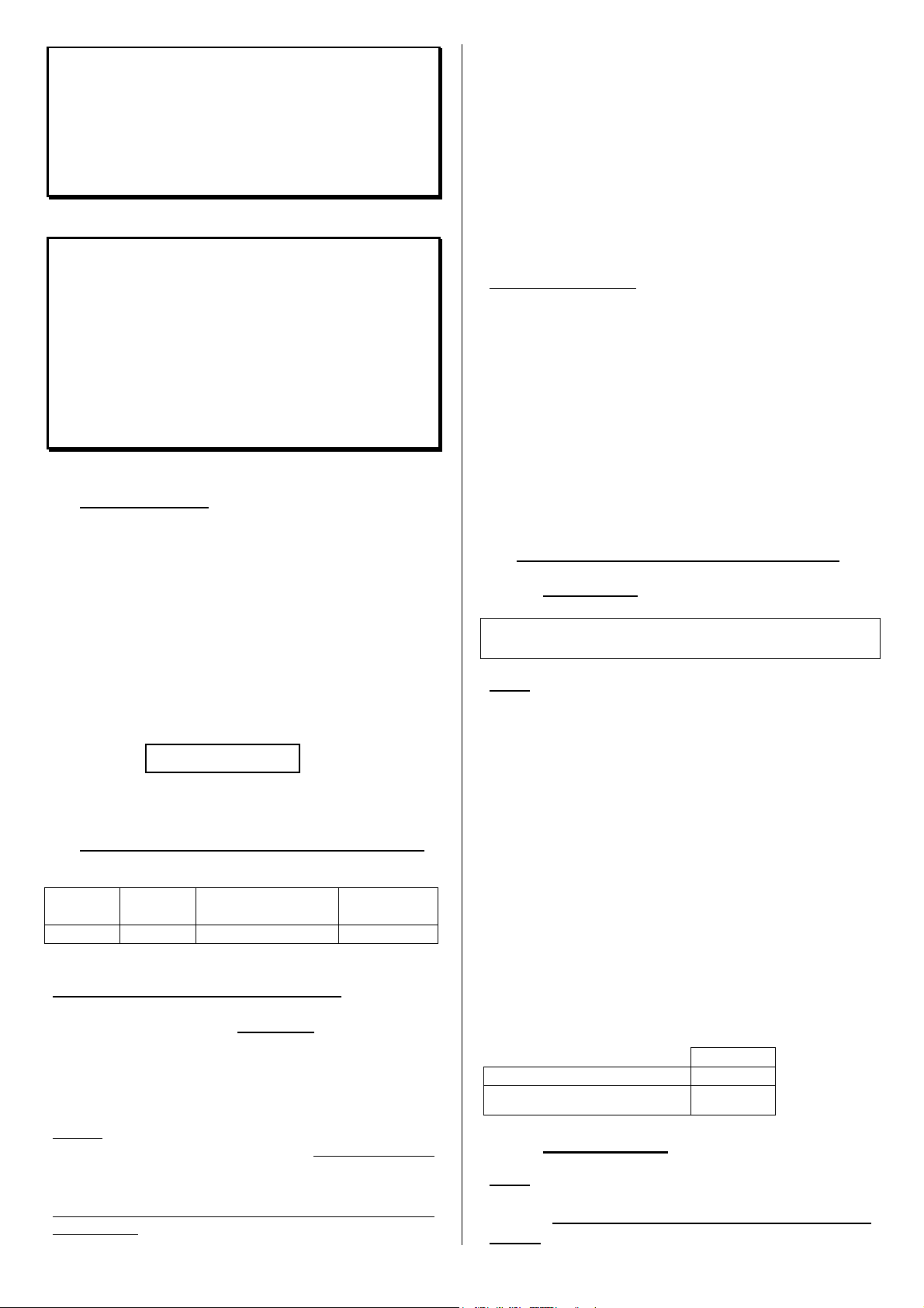
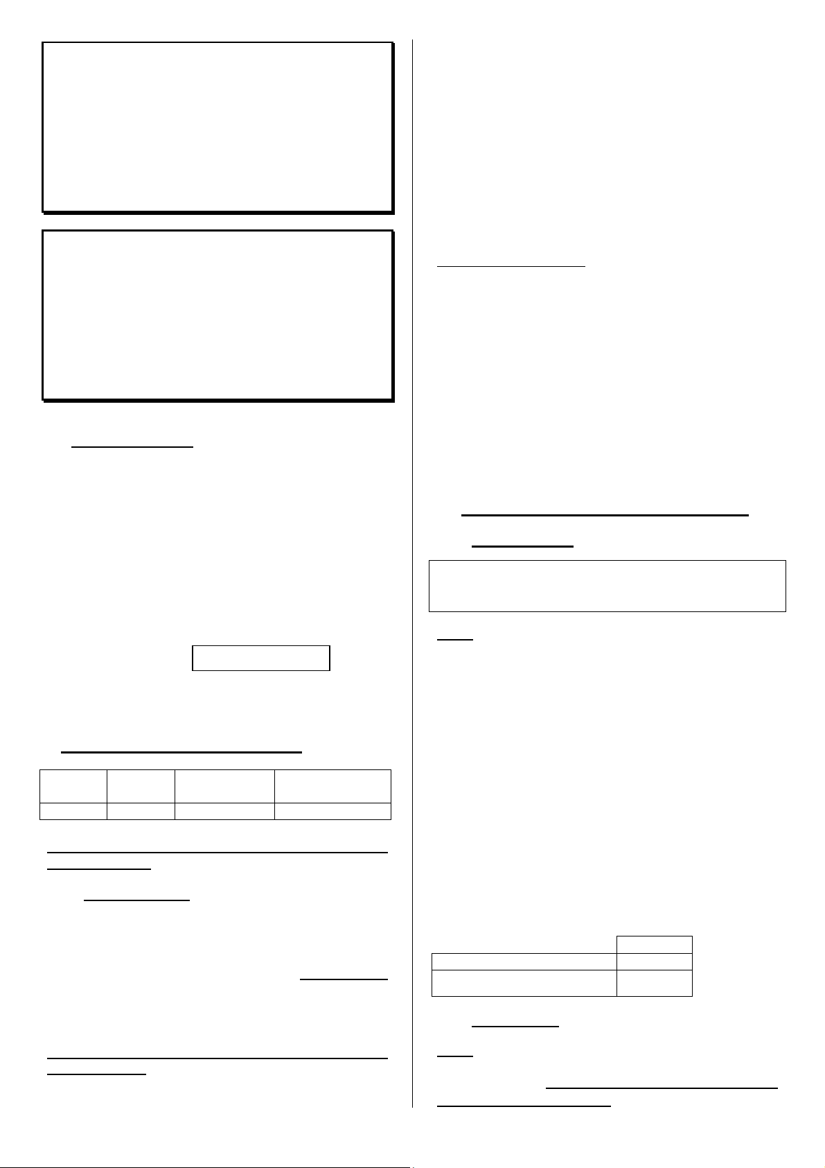
2 - PUISSANCE CALORIFIQUE NOMINALE
Puissance
nominale
11W 12 Pa 8,5 g/s 384°C
Fonctionnement intermittent et continu :
- Le fonctionnement intermittent nécessite un
rechargement tous les ¾ d’heure.
Il faut privilégier ce mode de fonctionnement
particulièrement respectueux de l’environnement.
- L’appareil peut également assurer un fonctionnement
continu quand les contraintes de l’intermittence ne
peuvent être respectées ou qu’une combustion lente
est recherchée.
Puissance calorifique nominale en fonctionnement
intermittent :
Tirage Débit massique des
fumées
Température
des fumées
. Obtenue sous un tirage de 12 Pa, au cours d’une
durée de feu de ¾ d’heure, avec une charge de 2,62
kg de bois dur (charme, chêne…) sous forme de 2
bûches de bois fendues de 8 à 11 cm diamètre
environ.
. Pour obtenir ce régime de puissance, recharger sur
un lit de braises de 300 g environ soit 3 cm
d’épaisseur.
La puissance annoncée est la puissance moyenne
obtenue au cours des essais, la tirette d’air en position
ouverture maxi.
La combustion lente :
. Obtenue sous un tirage de 6 Pa, la tirette d’air en
position fermée.
. Recharger sur un lit de braises d’environ 300 g (soit
3 cm d’épaisseur).
. Durée supérieure à 10 heures avec une bûche de
15 cm de bois dur non fendue, de 5,3 kg.
Les conditions d’allure normale permettent l’obtention
d’une puissance maximale à ne pas dépasser pour
obtenir un fonctionnement en toute sécurité.
La charge maximum est de 15 kg.
3 - DESCRIPTION ET ENCOMBREMENT
3.1 – Description
Le dessus de votre appareil est peint, ne rien poser
dessus sous peine de dégradation.
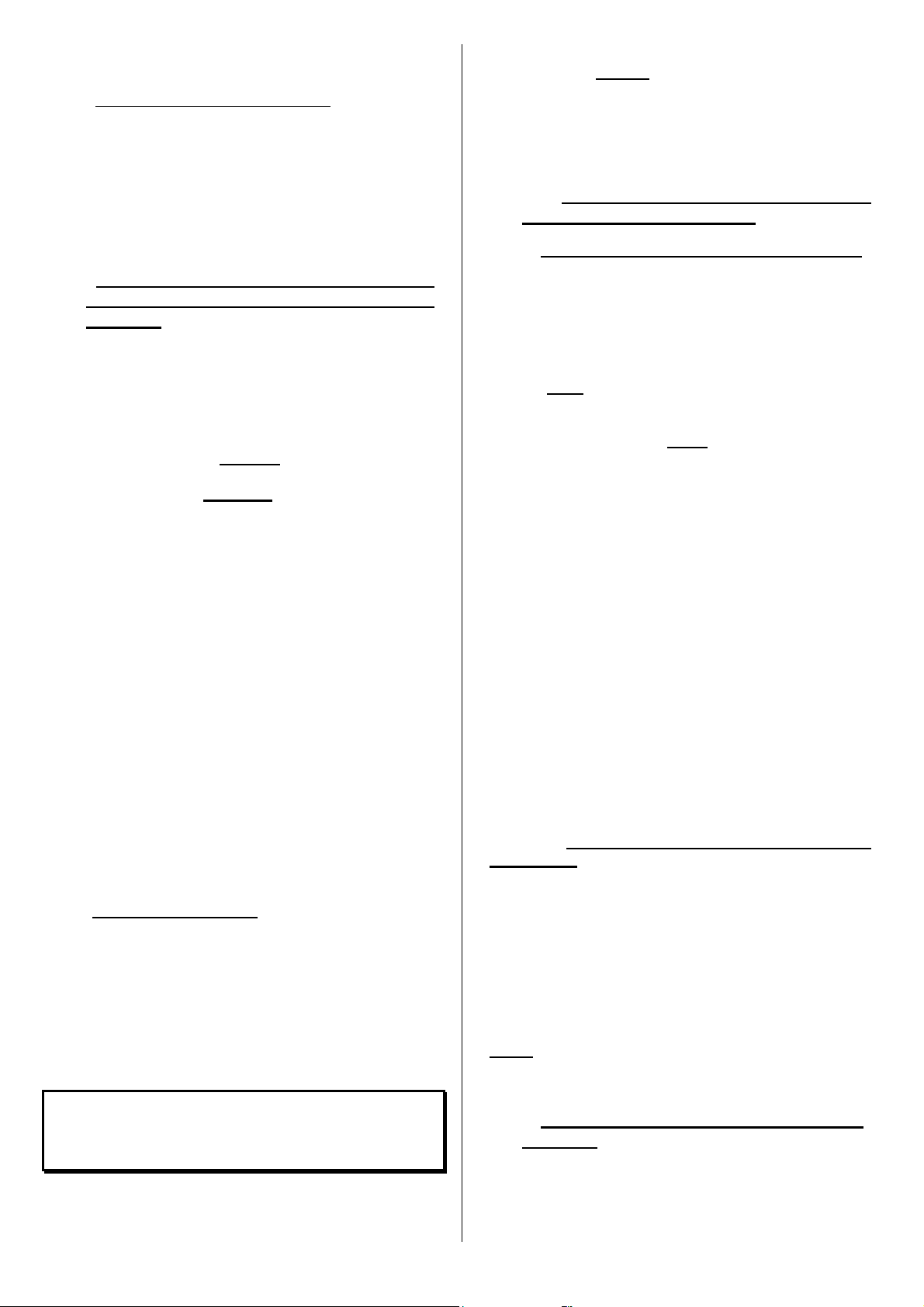
Fig. 1
Les principaux éléments constituant le poêle sont
indiqués ci-dessous :
(1) Poignée
(2) Porte de chargement
(3) Dessus
(4) Buse
(5) Ecran arrière
(6) Tirette de réglage d’air
(7) Tampon de buse
(8) Busette Ø 80 pour prise d’air de combustion
extérieur
Une entrée d’air secondaire est intégrée dans la partie
haute de la vitre de la porte pour la maintenir propre et
assurer une meilleure combustion du bois.
La tirette de réglage d’air, située en partie basse
permet de choisir une allure de feu.
Poids net de l’appareil
Poids nu (sans porte, déflecteur,
grille, vermiculites, dessus)
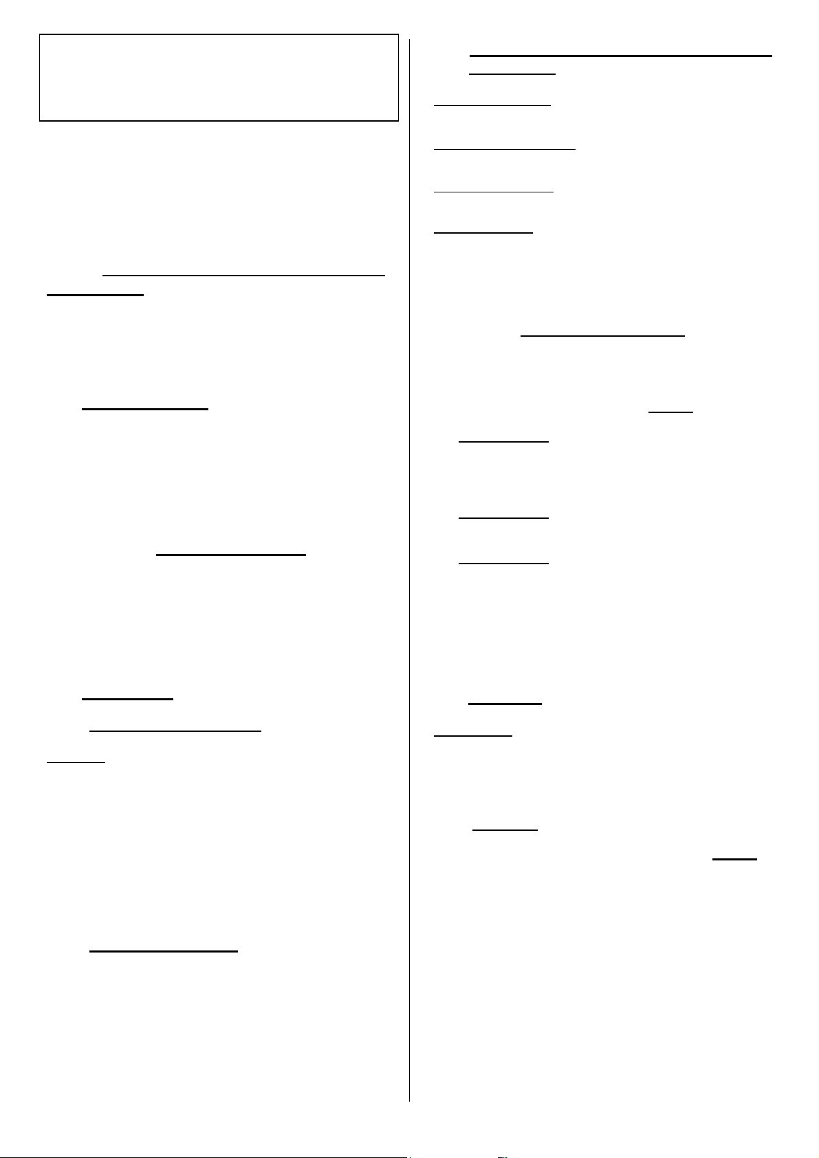
3.2 – Encombrement
Fig. 2
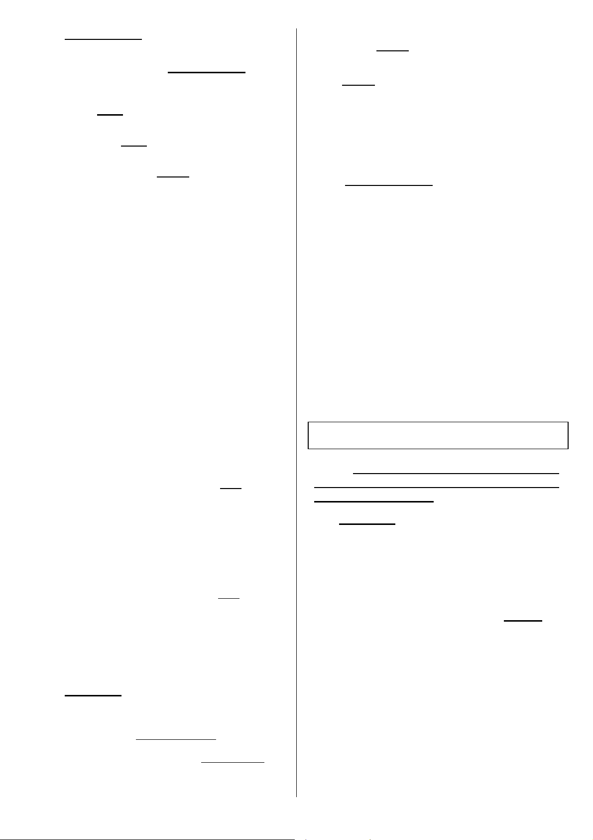
3.3 – Raccordement des fumées à l’arrière
(Fig.3)
4
C077AP
128 kg
86 kg
Page 5
Votre appareil est configuré pour un raccordement des
fumées sur le dessus, cependant il est possible de le
transformer pour un raccordement à l’arrière si
nécessaire :
- Lever et retirer l’écran arrière, ôter la
prédécoupe en perçant dans les 3 petits trous.
(foret Ø6). Fig. 3a.
- Ouvrir la porte et retirer les 5 écrous H (clé pipe
de 7mm) qui sont situés dans les orifices J Fig.
3b.
- Retirer le dessus Fig. 3a.
- Ôter les 2 écrans de dessus.
- Boucher les trous des écrans de dessus à
l’aide des obturateurs et des vis qui sont dans
le cendrier du foyer.
- Retirer et inverser la buse et le tampon.
- Remettre les 2 écrans de dessus et le
dessus.
- Remettre les 5 écrous H qui sont situés dans
les orifices J Fig. 3b.
- Placer sur le dessus, le tampon décoratif
qui se trouve dans le cendrier.
- Remettre l’écran arrière
4 – CONDITIONS D’INSTALLATION DE
L’APPAREIL
L'installation ne devra pas être modifiée par l'utilisateur.
Nous rappelons ci-après les recommandations
élémentaires à respecter, celles-ci ne se substituent en
aucun cas à la stricte application de l'ensemble du DTU
24-2-2.
4.1 - Dénomination des diverses parties du
circuit d'évacuation des fumées (Fig. 4)
4.2 - Nature et caractéristiques
dimensionnelles du conduit de fumée auquel
doit être obligatoirement raccordé l'appareil
4.2.1 - Nature du conduit de fumée
4.2.1.1 - Cas d'un conduit neuf
Utilisation des matériaux suivants :
• Boisseaux de terre cuite conformes à la NF P
51-311.
• Boisseaux en béton conformes à la NF P 51-321.
• Conduits métalliques composites conformes aux
NF D 35-304 et NF D 35-303 ou ayant reçu un
Avis Technique favorable pour cet usage.
• Briques en terre cuite conformes à la NF P 51-
301.
• Briques réfractaires conformes à la NF P 51-302.
L'utilisation de matériaux isolés d'origine permet
d'éviter la mise en place d'une isolation sur le
chantier, notamment au niveau des parois de la
souche (résistance thermique minimale : 0,43 m²
k/W).
4.2.1.2 - Cas d'un conduit existant
L'installateur prend à son compte la responsabilité
des parties existantes. Il doit vérifier l'état du conduit
et y apporter les aménagements nécessaires pour
son bon fonctionnement et la mise en conformité
avec la réglementation.
Ramoner le conduit puis procéder à un examen
sérieux pour vérifier :
• La compatibilité du conduit avec son utilisation.
• La stabilité.
• La vacuité et l'étanchéité (annexe II du DTU 24-
1).
Si le conduit n'est pas compatible, réaliser un
tubage à l'aide d'un procédé titulaire d'un Avis
Technique favorable, ou mettre en place un
nouveau conduit.
4.2.2 - Section minimale du conduit
Boisseaux carrés ou rectangulaires : section minimale
2,5 dm².
Conduits circulaires : diamètre minimal 153 mm.
Dans tous les cas, la section du conduit doit être au
moins égale à celle de la buse de raccordement sur
l'appareil.
4.2.3 - Quelques préconisations générales
• Un bon conduit doit être construit en matériaux
peu conducteurs de la chaleur pour qu'il puisse
rester chaud.
• L'habillage du conduit doit permettre de limiter la
température superficielle extérieure à :
- 50 °C, dans les parties habitables
- 80 °C, dans les parties non habitables ou
inaccessibles.
• Il doit être absolument étanche, sans rugosité et
stable.
• Il ne doit pas comporter de variations de section
brusques (pente par rapport à la verticale
inférieure à 45°).
• Il doit déboucher à 0,4 m au moins au-dessus du
faîte du toit et des toits voisins.
• Deux appareils ne doivent pas être raccordés sur
un même conduit.
• Sa face extérieure doit être éloignée de 16 cm au
moins de tout bois et matière combustible.
• Les boisseaux doivent être montés partie mâle
vers le bas afin d'éviter le passage des coulures à
l'extérieur.
• Le conduit ne doit pas comporter plus de deux
dévoiements, c'est à dire plus d'une partie non
verticale :
- Si c'est un conduit maçonné :
L'angle des dévoiements ne doit pas excéder 45°
pour une hauteur totale du conduit limitée à 5 m.
5
Page 6
Pour une hauteur supérieure, l'angle de
dévoiement est limité à 20°.
- Si c'est un conduit métallique isolé :
L'angle des dévoiements ne doit pas excéder 45°
avec une limitation de hauteur de 5 m entre le
haut et le bas du dévoiement. La hauteur totale
du conduit n'est pas limitée.
• L'étanchéité, l'isolation, les traversées de plafond
et plancher, les écarts au feu doivent être réalisés
dans le strict respect du DTU 24-2-2.
4.3 - Nature et caractéristiques du conduit de
raccordement entre l’appareil et le conduit
de fumée
• Un conduit de raccordement doit être installé entre
l'appareil et le débouché du conduit de fumée. Ce
conduit doit être réalisé à l'aide d'un tubage
polycombustible rigide ou flexible, justifiable d'un
Avis Technique favorable pour une desserte directe
de foyer fermé.
A noter que sont interdits : l'aluminium, l'acier
aluminié et l'acier galvanisé.
A noter que sont autorisés : la tôle noire (ép. Mini
2 mm), la tôle émaillée (ép. Mini 0,6 mm), l'acier
inoxydable (ép. Mini 0,4 mm).
• Ce conduit doit être visible sur tout son parcours
par une trappe ou grille de visite et ramonable de
façon mécanique. Sa dilatation ne doit pas nuire à
l'étanchéité des jonctions amont et aval ainsi qu'à
sa bonne tenue mécanique et à celle du conduit de
fumée. Sa conception et, en particulier, le
raccordement avec le conduit de fumée doit
empêcher l'accumulation de suie, notamment au
moment du ramonage.
• Les jonctions avec l'appareil d'une part et le conduit
de fumée d'autre part doivent être réalisées dans le
strict respect du DTU 24-2-2 et des spécifications
du constructeur du tube, en utilisant tous les
composants préconisés (embouts, raccords, etc...).
• Dans le cas où le conduit de raccordement est
horizontal, une pente ascendante de 5 cm par
mètre doit exister.
4.4 - Conditions de tirage
• Le tirage est mesuré sur le conduit de
raccordement à environ 50 cm au-dessus de la
buse de l'appareil.
• Tirage nécessaire au bon fonctionnement porte
fermée :
- 6 Pa en allure réduite (0,6 mm de CE).
L’évaluation du tirage prévisible en fonction des
caractéristiques du conduit étant peu sûr, il est
recommandé d’installer systématiquement un volet
modérateur.
• Le modérateur permet d’obtenir un bon
- 12 Pa en allure normale (1,2 mm de CE).
fonctionnement, même dans des conditions de
tirage importantes (conduits hauts, tubage).
Le modérateur doit être facilement visible,
accessible (Fig. 5)
et installé dans la pièce où se
trouve l’appareil.
• Le volet modérateur de tirage n'a pas d'influence
sur le fonctionnement de l'appareil lorsque la porte
est ouverte.
4.5 – Apport d’air nécessaire au bon
fonctionnement de l’appareil
4.5.1 – Ventilation du local où l’appareil est installé
• Le fonctionnement de l'appareil nécessite un apport
d'air supplémentaire à celui nécessaire au
renouvellement d'air réglementaire. Cette amenée
d'air est obligatoire lorsque l'habitation est équipée
d'une ventilation mécanique.
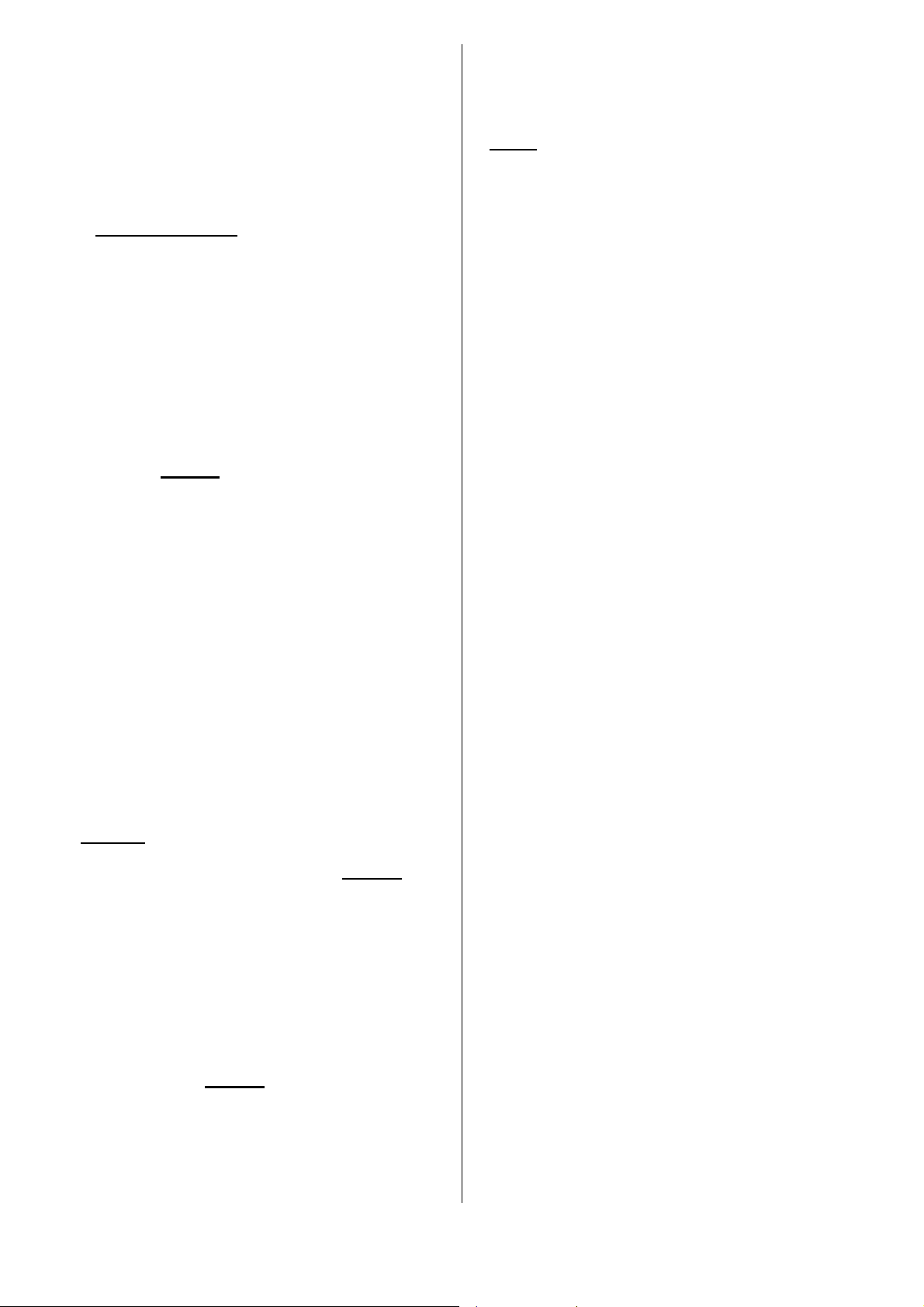
• La prise d'amenée d'air doit être située soit
directement à l'extérieur, soit dans un local ventilé
sur l'extérieur, et être protégée par une grille (voir
disposition conseillée Fig. 6).
A : FAVORABLE
Face sous vent dominant : favorise
l’écoulement de l’air frais et des fumées.
B : DEFAVORABLE
Face opposée au vent dominant.
• La sortie d'amenée d'air doit être située le plus près
possible de l'appareil. Elle doit être obturable
lorsqu'elle débouche directement dans la pièce.
Pendant le fonctionnement de l’appareil, s’assurer
qu’elle soit libre de toute obstruction.
• La section d'entrée d'air doit être au minimum égale
au quart de la section du conduit de fumée avec un
minimum de 50 cm² pour une utilisation uniquement
porte fermée.
• Il peut être nécessaire de stopper l'extracteur de la
ventilation mécanique pour éviter le refoulement
des fumées dans la pièce lors de l'ouverture de la
porte.
4.5.2 – Raccordement extérieur de l’air de
combustion
• L’appareil est équipé d’une prise d’air située à
l’arrière de celui-ci et permettant un apport d’air
extérieur par l’intermédiaire d’une gaine en
aluminium Ø 80 dont la longueur ne devra pas
excéder 3 mètres.
• Fixer votre gaine sur la busette à l’aide d’un collier
métallique.
NOTA : En aucun cas, la ventilation du local où est
installé l’appareil (paragraphe 4.5.1) ne doit être
supprimée.
4.6 - Nature des murs et des parois avoisinant
l'appareil
• Placer le poêle à la distance minimale de 300 mm
des murs arrière et latéraux de l’habitation et de
tous matériaux combustibles.
6
Page 7
• Pour protéger le sol contre le rayonnement de
chaleur, et la chute éventuelle de combustible
poser l’appareil sur un écran métallique
réfléchissant (ou un sol carrelé) couvrant toute la
surface du sol située sous et devant l’appareil.
• L’appareil doit être installé sur un sol avec une
capacité portante suffisante. Si une construction
existante ne satisfait pas à cette condition
préalable, des mesures adéquates (par exemple,
l’installation d’une plaque de répartition de charge)
doivent être prises pour permettre au sol de
supporter l’appareil.
5 – CONDITIONS D’UTILISATION DE
L’APPAREIL
Votre poêle est un véritable appareil de chauffage :
• Rendement élevé.
• Fonctionnement en allure réduite de longue durée.
5.1 - Premier allumage
• Ne pas raccorder le poêle sur un conduit
desservant plusieurs appareils.
• Après le premier allumage (voir paragraphe
5.4.1), faire un feu modéré pendant les premières
heures en limitant le chargement de l'appareil (une
bûche de ∅ 15 cm) avec la tirette d'air en allure
intermédiaire (voir paragraphe 5.4.2) : montée en
température progressive de l'ensemble des
éléments de la cheminée et dilatation normale de
l'appareil.
• Pendant les premières utilisations, une odeur de
peinture peut se dégager de l'appareil : aérer la
pièce pour limiter ce désagrément.
5.2 - Combustible
5.2.1 - Combustible recommandé
Bois dur : chêne, charme, hêtre, châtaignier, etc... en
bûche de 50 cm de longueur.
Hauteur maximale de chargement : 20 cm.
Nous vous conseillons d'utiliser du bois très sec (20 %
d'humidité maximum), soit 2 ans de stockage sous abri
après la coupe, afin d'obtenir de meilleurs rendements
et d'éviter le bistrage du conduit de fumée et des vitres.
Eviter l'utilisation des bois résineux (pins, sapins,
épicéas...) qui nécessitent un entretien plus fréquent de
l'appareil et du conduit.
5.2.2 - Combustibles interdits
Tous les combustibles autres que le bois sont interdits,
notamment le charbon et ses dérivés.
Les flambées de petits bois, sarments, planchettes,
paille, carton sont dangereuses et à exclure.
L’appareil, ne doit pas être utilisé comme un
incinérateur à déchets.
5.3 - Emploi des organes de manoeuvre et des
accessoires
Poignée de porte : Elle doit être manœuvrée par
l’intermédiaire de la main froide.
Tirette de réglage d’air : Elle doit être manœuvrée par
l’intermédiaire de la main froide.
Main froide (Fig. 7) : elle sert à manœuvrer la poignée
de porte et à extraire le cendrier.
Raclette (Fig. 8) : elle est utilisée pour le décendrage et
sert à arranger les bûches dans le foyer en fonction de
l’évolution de la combustion.
Ne vous brûlez pas les mains inutilement, servez-vous
des accessoires.
REGISTRE D’ALLUMAGE
La position Allumage est obtenue en manoeuvrant la
tirette directement avec la main : cette position ne doit
être utilisée que lorsque l’appareil est ‘’froid’’ et en
effectuant les opérations suivantes (Fig. 9) :
• Opération n°1 :
Tirer la tirette de réglage d’air primaire jusqu’à la
butée correspondant au verrouillage de la ‘’Position
Allumage’’.
• Opération n°2 :
Lever la tirette de réglage.
• Opération n°3 :
Tirer la tirette en position haute au maximum : vous
êtes en ‘’Position Allumage’’.
Après l’allumage, pour revenir en position d’allure
normale, d’allure intermédiaire ou d’allure lente, utiliser
le tisonnier pour pousser la tirette de réglage d’air qui
peut être chaude.
5.4 - Utilisation
ATTENTION : cette position allumage ne doit être
utilisée qu’à l’allumage de votre appareil. Une fois
l’allumage effectué, la tirette doit être repoussée.
Vous risquez d’endommager votre appareil si vous
ne respectez pas ces recommandations.
5.4.1 - Allumage
•
Mettre la tirette d’air en position allumage (Fig. 9)
• Placer sur la grille du papier froissé et du petit bois
très sec (brindilles), puis des branches de bois
fendues de section plus importante (∅ 3 à 5 cm).
• Enflammer le papier et refermer la porte (la laisser
légèrement entrouverte pour accélérer
l'embrasement en évitant le refoulement de fumée
hors de l’appareil).
• Lorsque la charge de "petit bois" est bien
enflammée, ouvrir la porte, charger l'appareil avec
le combustible recommandé.
• Repousser complètement le booster d’allumage.
7
Page 8
5.4.2 - Fonctionnement
• L'allure désirée est obtenue en agissant sur la
tirette de réglage d’air (Fig. 1 Rep. 6) et en
choisissant une charge correspondant aux besoins.
- Tirer la tirette complètement pour être en allure
maxi (Fig. 9).
- Pousser la tirette complètement pour être en
allure mini (Fig. 9).
- Choisissez une position intermédiaire pour une
allure intermédiaire (Fig. 9).
• Pour obtenir une allure lente de longue durée,
procéder au chargement sur un lit de braises à
peine rougeoyantes.
• Pour obtenir un embrasement rapide, relancer le
feu avec du "petit bois", effectuer le chargement,
maintenir éventuellement la porte entrouverte
pendant quelques minutes pour accélérer
l’embrasement, en gardant l’appareil sous
surveillance, puis fermer la porte. Cette opération
permet d’accélérer la reprise, notamment si le bois
est humide.
• Effectuer les changements d'allure (passage de
l'allure normale à l'allure lente par exemple) avant
les rechargements, pendant la phase de
combustion des braises, pour permettre à l'appareil
et au conduit des fumées de changer
progressivement de régime.
• Pour éviter les refoulements des fumées et les
chutes de cendres dans la pièce, au moment des
rechargements, l’ouverture de la porte nécessite
plusieurs précautions : entrouvrir la porte, marquer
un temps d’arrêt pour amorcer le tirage, puis ouvrir
lentement la porte.
• Le fonctionnement continu en allure lente, surtout
pendant les périodes de redoux (tirage
défavorable) et avec du bois humide, entraîne une
combustion incomplète qui favorise les dépôts de
bistre et de goudron :
o Alterner les périodes de ralenti par des retours
en fonctionnement à allure normale.
o Privilégier une utilisation avec de petites
charges.
• Après un fonctionnement en allure lente, la vitre
peut s'obscurcir à cause d'un léger bistrage. Ce
dépôt disparaît normalement en fonctionnement à
plus vive allure par pyrolyse.
• La chambre de combustion doit toujours rester
fermée, sauf lors du rechargement, afin d’éviter
tout débordement de fumée.
5.4.3 - Décendrage
• L'air utilisé pour la combustion du bois arrive sous
la grille lorsque la tirette d’air est ouverte. Cet air
assure également le refroidissement de la grille. Il
est donc indispensable, pour obtenir les
performances optimales et éviter la dégradation
de
la grille sous l'effet de la surchauffe, d'éviter son
obstruction en procédant régulièrement au
décendrage et à l'évacuation des cendres.
- La raclette permet d'effectuer le décendrage de
la grille (Fig. 8)
.
- Le cendrier, situé sous la grille, est facilement
extrait en le tirant à l'aide de la main froide
(Fig. 7).
• Le niveau des cendres ne doit jamais atteindre la
grille en fonte de l'appareil.
• Enlever périodiquement les cendres
accidentellement répandues dans le compartiment
cendrier.
5.4.4 - Règles de sécurité
• Ne jamais jeter d'eau pour éteindre le feu.
• La vitre de l'appareil est très chaude : attention aux
risques de brûlures notamment pour les enfants.
• L'appareil dégage, par rayonnement à travers le
vitrage, une importante chaleur : ne pas placer de
matériaux, ni d'objets sensibles à la chaleur à une
distance inférieure à 1,50 m de la zone vitrée.
• Vider le contenu du cendrier dans un récipient
métallique ou ininflammable exclusivement réservé
à cet usage. Les cendres, en apparence refroidies,
peuvent être très chaudes même après quelques
temps de refroidissement.
• Ne pas mettre en place des matériaux facilement
inflammables au voisinage de l'appareil et dans le
bûcher.
• En particulier, ne pas stocker de bois sous
l'appareil.
• En cas de feu de cheminée, mettre la tirette d’air
en position fermée.
• Il est impératif de toujours maintenir fermées les
portes de chargement et de cendrier.
6 - CONSEILS DE RAMONAGE ET
D'ENTRETIEN DE L'APPAREIL ET DU
CONDUIT DE FUMEE
6.1 - Ramonage :
Le ramonage mécanique du conduit de fumée est
obligatoire, il doit être réalisé plusieurs fois par an dont
une fois au moins pendant la saison de chauffe. Un
certificat doit être établi par l'entrepreneur.
A l'occasion des ramonages, il faudra :
• Procéder au démontage du déflecteur (Fig. 10) :
- Démonter le déflecteur en le soulevant et en le
tirant vers l’avant.
- Laisser descendre la partie arrière du déflecteur
et le sortir.
- Pour remonter le déflecteur : agir dans l'ordre
inverse du démontage.
• Vérifier complètement l'état de l'appareil et en
particulier les éléments assurant l'étanchéité : joints
et organes de verrouillage, pièces d'appui (porte,
châssis).
8
Page 9
• Vérifier l'état du conduit de fumée et du conduit de
raccordement : tous les raccords doivent présenter
une bonne tenue mécanique et avoir conservé leur
étanchéité.
• Nettoyez l’appareil à la brosse et à l'aspirateur.
En cas d’anomalie : faire réparer l’appareil ou
l’installation par un professionnel.
6.2 – Entretien courant
• Le nettoyage de l’appareil doit être réalisé avec un
chiffon doux et de l’eau savonneuse ou un produit à
vitres sans alcool.
• Nettoyer les vitres avec un chiffon humide et de la
cendre. Si c'est nécessaire, utiliser un produit de
nettoyage spécifique en respectant les instructions
d'utilisation : attendre que l'appareil soit
complètement refroidi pour procéder à cette
opération.
• Nettoyer régulièrement la réglette d’admission d’air
secondaire (Fig. 11).
- Enlever à l'aspirateur les particules et
poussières qui sont coincées entre le guide d’air et
le verre. Si nécessaire glisser une fine lame ou
une feuille de carton rigide entre le guide d’air et
la vitre pour faciliter le nettoyage (déblocage des
particules).
Ces particules gênent la formation du film d'air
secondaire qui protège le vitrage du contact direct
avec les fumées et complète la combustion du
bois.
- Gratter avec l’extrémité d’un objet métallique
l’arrête inférieure de la réglette d’admission d’air
pour enlever le bistre qui a pu s’y agglomérer.
Ces opérations doivent être effectuées dès que le
verre est sale et impérativement après extinction
du foyer.
Si des traces de suies localisées et très marquées
(Fig. 11) réapparaissent et se multiplient, il est
nécessaire de démonter le guide d'air pour
effectuer un décrassage plus complet (Fig. 12) :
. Dégonder la porte et la poser à plat.
. Enlever les 3 vis.
. Enlever le guide d'air A et le nettoyer.
. Remonter l'ensemble et vérifier que le jeu de
vitrage préconisé est respecté.
Cette opération doit être effectuée par un
professionnel qualifié.
• Contrôler l'efficacité de la clenche de fermeture de
la porte et, si c'est nécessaire, effectuer les
réglages suivants (Fig. 13) :
- Durcir la fermeture de la porte :
. Desserer l’écrou
. Tourner progressivement l’axe hexagonal
excentrique
. Agir par ¼ de tour sur les 2 vis et
recommencer l'opération si cela est
nécessaire.
. Resserer l’écrou
NOTA
: Cette opération augmente ou diminue la
pression du joint d’étanchéité de la porte sur l’appareil
9
Page 10

7- CONDITIONS GENERALES DE GARANTIE
1. MODALITES
En dehors de la garantie légale, à raison des vices cachés, DEVILLE garantit le matériel en cas de vices apparents
ou de non-conformité du matériel livré au matériel commandé.
Sans préjudice des dispositions à prendre vis-à-vis du transporteur, les réclamations lors de la réception du
matériel sur les vices apparents ou la non-conformité, doivent être formulées auprès de DEVILLE par l’acheteur
dans les cinq jours de la constatation du vice par voie de lettre recommandée avec demande d’avis de réception. Il
appartient à l’acheteur de fournir toute justification quant à la réalité des vices ou des anomalies constatées.
L’acheteur doit, par ailleurs, laisser à DEVILLE toute facilité pour procéder à la constatation de ces vices ou
anomalies et pour y porter remède. De même l’acheteur doit tenir les matériels non conformes à la disposition de
DEVILLE, selon les instructions de cette dernière. Tout retour du matériel, pour quelque raison que ce soit, doit
faire l’objet d’un accord préalable formel de DEVILLE.
2. ETENDUE
La garantie de DEVILLE couvre, à l’exclusion de toute indemnité ou dommages-intérêts, le remplacement gratuit
ou la réparation du matériel ou de l’élément reconnu défectueux (hors pièces d’usure) par ses services à l’exclusion
des frais de main-d’œuvre, de déplacement et de transport.
Sur les appareils émaillés, les craquelures ne sont jamais considérées comme un défaut de fabrication. Elles sont
la conséquence de différence de dilatation tôle-émail ou fonte-émail et ne modifient pas l’adhérence. Les pièces de
rechange fournies à titre onéreux sont garanties six mois à partir de la date de facture ; toute garantie
complémentaire consentie par un revendeur de DEVILLE n’engage pas DEVILLE. La présentation du certificat de
garantie portant le cachet à date du revendeur DEVILLE est rigoureusement exigée lorsque la garantie est
invoquée. Ce certificat doit être présenté lors de la demande de réparation de l’appareil sous garantie, ou bien un
talon ou un volet détachable de ce certificat doit, selon l’organisation propre à DEVILLE, être retourné à celle-ci
dans les délais impartis. A défaut, la date figurant sur la facture émise par DEVILLE ne peut être prise en
considération. Les interventions au titre de la garantie ne peuvent avoir pour effet de prolonger celle-ci.
3. DUREE
La durée de la garantie contractuelle assurée par DEVILLE est de 2 ans (5 ans pour le corps de chauffe
foyers/inserts) à compter de la date d’achat de l’appareil par l’usager, sous réserve que les réclamations prévues
au titre des modalités ci-dessus aient été formulées dans les délais impartis. La réparation, le remplacement ou la
modification de pièces pendant la période de garantie ne peut avoir pour effet de prolonger la durée de celle-ci, ni
de donner lieu en aucun cas à indemnité pour frais divers, retard de livraison, accidents ou préjudices quelconques.
4. EXCLUSION
La garantie ne s’applique pas dans les cas suivants, sans que cette liste soit exhaustive :
Installation et montage des appareils dont la charge n’incombe pas à DEVILLE. En conséquence, DEVILLE ne peut
être tenue pour responsable des dégâts matériels ou des accidents de personne consécutifs à une installation non
conforme aux dispositions légales et réglementaires (par exemple l’absence de raccordement à une prise de terre ;
mauvais tirage d’une installation) ;
Usure normale du matériel ou utilisation ou usage anormal du matériel, notamment en cas d’utilisation industrielle
ou commerciale ou emploi du matériel dans des conditions différentes de celles pour lesquelles il a été construit.
C’est le cas par exemple du non-respect des conditions prescrites dans la notice DEVILLE : exposition à des
conditions extérieures affectant l’appareil telles qu’une humidité excessive ou variation anormale de la tension
électrique ;
Anomalie, détérioration ou accident provenant de choc, chute, négligence, défaut de surveillance ou d’entretien de
l’acheteur ;
Modification, transformation ou intervention effectuée par un personnel ou une entreprise non agréée par DEVILLE
ou réalisée avec des pièces de rechange non d’origine ou non agréées par le constructeur.
5. CONDITIONS PARTICULIERES DE GARANTIE
Ces conditions complètent et précisent les conditions générales de garanties ci-dessus et ont primauté sur cellesci, se reporter au feuillet ci joint « Conditions particulières de vente DEVILLE – Garantie ».
10
Page 11

CONTENT
Pages
1 - DESIGNATION............................................................................................................................................. 12
2 – NOMINAL CALORIFIC POWER................................................................................................................. 12
3 - DESCRIPTION AND DIMENSIONS............................................................................................................. 12
3.1 - Description
3.2 – Dimensions
3.3 - Smoke connection on the top
4 - INSTALLATION REQUIREMENTS FOR THE APPLIANCE........................................................................ 13
4.1 - Definition of components included in the smoke evacuation system
4.2 - Characteristics and size of the smoke flue to which the appliance must be connected
4.2.1 - Type of Smoke Flue
4.2.1.1 - New smoke flue
4.2.1.2 - Existing smoke flue
4.2.2 - Minimum Flue Section
4.2.3 - General Recommendations
4.3 - Nature and characteristics of the vent connector between the appliance and the smoke duct
4.4 – Draught requirements
4.5 – Contribution of the necessary air for the proper working of the appliance
4.5.1
-
Ventilation of the area in which the appliance is to be installed
4.5.2 - External combustion air connection
4.6 – Walls in the vicinity of the appliance
5 – USE REQUIREMENTS FOR THE APPLIANCE......................................................................................... 14
5.1 – First lighting
5.2 – Fuel
5.2.1 – Recommended fuels
5.2.2 – Forbidden fuels
5.3 – Use of the operation parts and equipment
5.4 - Use
5.4.1 - Lighting
5.4.2 - Working
5.4.3 – Ash removal
5.4.4 – Safety regulations
6 – ADVICE ON CHIMNEY-SWEEPING AND STOVE AND SMOKE FLUE MAINTENANCE........................ 16
6.1 – Sweeping
6.2 – usual cleaning
7 – GLOBAL TERMS OF WARRANTY ............................................................................................................ 18
11
Page 12
You are advised to have a thorough and
careful reading of the instructions for use in
order to get the best use and satisfaction of
your DEVILLE appliance.
The fact of not respecting the fixing, the
installing and the use istructions involves the
responsibility of the person who doesn’t
respect them.
THIS STOVE MUST BE INSTALLED IN
ACCORDANCE TO THE CURRENT D.T.U.
SPECIFICATIONS..
The stove must be installed by a skilled
professional.
All the local and national regulations as well
as the European standards have to be
respected when the stove is used.
The appliance mustn’t be modified.
1 - DESIGNATION
Your DEVILLE appliance complies with the essential
requirements of Directive 89/106/EEC Construction
Products according to Appendix ZA of the EN 13240
Standard.
It is an intermittent and continuous combustion heat
appliance using a grate that operates exclusively using
wood, with a half-closed combustion chamber.
Note down the serial number written on the descriptive
plate stuck on the appliance and on the certificate of
guarantee, write it down in the following box :
Serial number
This number will be necessary to identify your appliance
when spare parts will be needed.
2 – CALORIFIC NOMINAL POWER
Nominal
power
11 kW 12 Pa 8,5 g/s 384°C
Intermittent and continuous running :
The intermittent running needs a reload every three
quarters of an hour.
This choice of operation is to be favoured as it is
environmentally-friendly.
The appliance can also ensure a continuous running
when the intemittent constraints can’t be respected or
when a reduced power is wanted.
Nominal calorific power with an intermittent working :
. Obtained under a draught of 12 Pa, during a 45-
minute fire period, with a load of 2,62 kg of hard wood
(hornbeam, oak, and so on) in the form of two split
wooden logs of about 8-11cm in diameter.
. To get this heat power, reload on an ash bed of about
300 g that is to say 3 cm thick.
Draught Smoke output / weight Smoke
temperatures
The given power is the average power obtained in the
tests with the air intake damper opened to its
maximum.
The slow combustion :
. Obtained with a 6 Pa draught, with the air intake
damper closed
. Reload on an ash bed of about 300 g (3 cm thick).
. Duration in excess of 10 hours with an unsplit, 5.3 kg,
15 cm hard wood log.
Normal speed conditions allow to get a maximum
power which is not to be exceeded to guarantee a
running in complete safety.
The maximum loading is 15 kg of wood.
3 - DESCRIPTION AND DIMENSIONS
3.1 - Description
The top of your appliance is painted, do not place
anything on it as this could deteriorate it.
Fig. 1
The main elements constituting the stove are indicated
below :
(1) Handle
(2) Loading door
(3) Top
(4) Tube
(5) Rear screen
(6) Air adjustment knob
(7) Nozzle damper
(8) Ø 80 nozzle for external combustion air intake
A secondary air intake is incorporated into the upper
part of the door window in order to keep it clean and to
ensure better combustion of the wood.
The air regulation lever, located at the bottom, is used
to select a burning speed.
Net weight of the appliance
Gross weight (without door,
deflector, grate, vermiculite, top)
3.2 - Dimensions
Fig. 2
3.3 – Smoke duct connection to the rear (Fig.3)
Your appliance is configured for a connection of the
smoke ducts on the top, however, it is possible to alter
it for a connection at the rear if necessary:
- Lift and remove the rear screen, remove the
pre-cut part by drilling in the 3 small holes. (Ø6
drill bit). Fig. 3a.
- Open the door and remove the 5 nuts H (7mm
box wrench) which are housed in the openings
J Fig. 3b.
- Remove the top Fig. 3a.
- Remove the 2 top screens.
12
C077AP
128 kg
86 kg
Page 13
- Fill the holes in the top screens using the
obturators and screws which are in the hearth
ash box.
- Remove and reverse the nozzle and the
damper .
- Refit the 2 top screens and the top .
- Refit the 5 nuts H which are housed in the
openings J Fig. 3b.
- On the top, place the decorative damper
which is in the ash box.
- Refit the rear screen .
4 – INSTALLATION REQUIREMENTS FOR
THE APPLIANCE
The installation cannot be modified by the user.
We remind you hereafter of the prior recommendations
to be respected, these will have to be added to the strict
application of the whole DTU 24-2-2.
4.1 – Definition of components included in the
smoke evacuation system(Fig. 4)
4.2 – Characteristics and size of the smoke
flue to which the appliance must be
connected
4.2.1 - Type of Smoke Flue
4.2.1.1 - New Smoke Flue
Use of the following materials:
• Fireclay flue blocks compilant with French
Standard NF P 51-311
• Concrete flue blocks compliant with NF P 51-
321
• Composite metal pipes compliant with NF D 35-
304 and NF D 35-303 or which have received
"Avis Technique" approval (*) for this use
• Fireclay bricks compliant with NF P 51-301
• Refractory bricks compliant with NF P 51-302
The use of certified insulating materials means that
on-the-spot insulating work can be avoided,
particularly where the chimney stack is concerned
(minimum thermal resistance 0.43 m2 k/W).
4.2.1.2 -
The installer is responsible for existing parts. He
should check the condition of the flue and carry out
any work required in order to ensure that it is in
proper working order and compliant with the
regulations in force.
He should sweep the flue and then check the
following very thoroughly :
• Compatibility of the flue with the intended use ;
• Stability
• That the flue is empty and smoke-tight (DTU 24-
Existing Smoke Flue
1, Appendix II).
If the flue is not compatible, make a casing using an
approved method "Avis Technique" certificats (*) or
install a new flue.
(*) French assessment and certification system
4.2.2 – Minimum flue section
Square or oblong flue blocks : minimum section 2,5
dm².
Circular flues : minimum diameter 153 mm.
In all cases, the cross section of the pipe must be at
least equal to that of the connecting nozzle on the
appliance.
4.2.3 - General Recommendations
• A good flue will be built of materials with low heat
conducting properties so that it stays hot.
• Flue casing should be such as to limit the external
surface temperature to the following :
- 50°C in living areas
- 80°C in non-living or inaccessible areas
• lt should be completely smoke-tight, stable and
have no rough spots.
• There should be no sudden changes in section
(slope in relation to the vertical less than 45°).
• It should extend at least 0,4 m above the ridge of
the roof and of adjacent roofs.
• Two appliances should not be connected to the
same flue.
• The exterior face should be at least 16 cm away
from any wood or combustible materials.
• Flue blocks should be placed with the male part
towards the bottom so as to avoid any leaks to the
outside.
• The flue should include no more than two changes
of direction, i.e. no more than one non-vertical
section.
- If the flue is in masonry :
The bend angle should not exceed 45° over a total
flue height limited to 5 m. For any greater height,
this angle should not exceed 20°.
- If it is an insulated metal flue :
The bend angle should not exceed 45° with the
height limited to 5 m between the top and bottom
of the bend. There is no limitation as to total flue
height.
• Smoke-tightness, insolation, openings in walls or
floors and sale fire distances should all strictly
comply with the provisions of DTU 24-2-2.
13
Page 14
4.3 – Nature and characteristics of the vent
connector between the appliance and the
smoke duct
• A vent connector must be installed between the
appliance and the outlet of the smoke duct. This
connector must be made by means of a rigid or
flexible multi-fuel casing, justifiable by a favourable
Technical Opinion for a direct closed hearth
service.
lt should be noted that the following are forbidden :
aluminium, aluminium steel and galvanized steel.
The following are approved : black plate (min.
thickness 2 mm), enamelled plate (min. thickness
0,6 mm) and stainless steel (min. thickness 0,4
mm).
• The flue must be visible over its whole length
through a grille or inspection flap and be able to be
swept by mechanical means. Any expansion should
not adversely affect the smoke-tightness of the
joins at either end or its mechanical performance or
that of the smoke flue. lts design, and more
especially the connection between it and the smoke
flue, should be such as to prevent the accumulation
of soot, particularly when it is being swept.
• Connections to the appliance and the flue should
strictly comply with DTU 24.2.2 and with the
specifications of the pipe ; they should include all
the recommended parts (end pieces and all other
fittings).
• If the vent connector is horizontal, there must be an
ascending slope of 5 cm per metre.
4.4 – Draught conditions:
• Draught is measured on the connecting pipe at a
point approximately 50 cm above the outlet on the
appliance.
• The following draught is required for proper working
with the door closed :
- 6 Pa at reduced speed (0,6 mm WG)
-12 Pa at normal speed (1,2 mm WG)
As there is always some doubt as to any evaluation
of the possible draught depending on flue
characteristics, it is advisable to systematically
install a damper.
• The regulator enables the appliance to work
properly, even under important draught conditions
(high ducts, casing). The regulator must be easily
visible, accessible (Fig. 5) and installed in the room
where the appliance has been placed.
• The damper does not affect stove performance
when the door is open.
4.5 - Contribution of the necessary air for the
proper working of the appliance
4.5.1 – Ventilation of the area in which the
appliance is to be installed
• The appliance needs air in addition to the air
required by the statutory air change rate. This is
obligatory when the dwelling includes mechanical
ventilation.
• The air intake should give directly to the outside or
should be located in an area ventilated to the
outside ; it should also be protected by a grille (see
advised layout Fig. 6).
A : FAVOURABLE
Face in prevailing wind, favour the flow of fresh
air and smokes.
B : UNFAVOURABLE
Face opposite prevailing wind.
• The air supply exit must be located as close to the
appliance as possible. It must be able to be capped
when it emerges directly into the room. While the
appliance is working, make sure that it is free of
any obstruction.
• The air intake section should be at least equal to
one-quarter of the section of the smoke flue with a
minimum of 50 cm2 for use only with the doors
closed.
• It may be necessary to stop the extractor of the
mechanical ventilation so as to avoid smoke
coming back into the room when the door is
opened.
4.5.2 – External combustion air connection
• The appliance is equipped with an air intake
located at the back that allows a contribution of
external air via an Ø 80 aluminium duct that must
not be longer than three metres.
• Attach your duct to the nozzle by means of a metal
collar clamp.
NOTA : Under no circumstances should the ventilation
of the room in which the appliance is installed
(Paragraph 4.5.1) be eliminated.
4.6 – Walls in the vicinity of the appliance
• Place the stove at a distance of at least 300mm
from the back and side walls of the room and from
all combustible materials.
• To protect the floor from heat radiation, and from
any possible falling fuel, put the appliance on a
reflective metal screen (or a tiled floor) covering the
entire surface of the floor beneath and in front of
the appliance.
• The appliance must be installed on a floor with a
sufficient load-bearing capacity. If an existing
construction does not satisfy this prerequisite,
adequate measures must be taken (for example,
the installation of a load distribution plate) in order
to enable the floor to support the appliance.
5 –
USE REQUIREMENTS FOR THE
APPLIANCE
Your stove is a real heating appliance :
14
Page 15

• High output.
• Slow speed running for a long period of time.
5.1 - First lighting
• Do not connect the stove to a pipe linked to several
appliances.
• After the first lighting (see paragraph 5.4.1), make
a moderate fire in the first hours limiting the loading
in the appliance (a log of ∅ 15 cm) with the air
intake damper in an intermediate position (see
paragraph 5.4.2) : progressive rise in temperature
of all the elements of the fireplace and normal
expansion of the appliance.
• During the first uses, a paint odor can come out
from the appliance : ventilate the room to limit this
inconvenience..
5.2 - Fuel
5.2.1 – Recommanded fuel
Hard wood : oak, hornbeam, beech, chestnut tree, etc...
in log of 50 cm long.
Maximum loading height: 20 cm.
We recommend you to use very dry wood (20 %
maximum humidity), that is a 2-year store under shelter
after cutting, to get better outputs and to avoid the
darking of the smoke flue and of the windows.
Avoid the use of conifers (pines, firs, spruces...) which
ask for a more frequent cleaning of the appliance and
the flue.
5.2.2 – Forbidden fuels
All fuels except wood are forbidden, especially coal and
its by-products.
Fires with twigs, twinings, small boards, straw,
cardboard are dangerous and banned.
The appliance must not be used as a waste incinerator.
5.3 - Use of the operation parts and equipment
Door handle : it must be handled thanks to the cold
hand.
Air intake control lever : it must be handled thanks to
the cold hand.
Cold hand (Fig. 7) : It is used for manoeuvring the door
handle and for taking out the ashes tray.
Scraper (Fig. 8) : it is used to remove and to arrange
the logs in the fireplace according to the combustion.
Do not burn your hands uselessly. Use the accessories.
LIGHTING DAMPER
The lighting postion is obtained through moving the
damper directly with the hand : this position can only be
used when the appliance is ‘cold’ and in making the
following operations (Fig. 9) :
• Operation n°1
:
Pull the primary air lever until the stop
corresponding to the locking of the "Lighting
position".
• Operation n°2 :
Lift the air intake damper.
• Operation n°3 :
Pull the lever to its maximum height : you are in the
"Lighting Position".
After the lighting, to come back to normal speed
position, intermediate speed or slow speed, use the
poker which can be hot to push the damper.
5.4 - Use
NB: this lighting position must only be used when
lighting your appliance. Once it is lit, the lever must
be pushed back. You risk damaging your appliance
if you do not respect these recommendations. You
are likely to damage your appliance if you do not
comply with these recommendations.
5.4.1 - Lighting
• Put the air intake damper in lighting position (Fig.
9).
• Place crumpled paper and small and very dry parts
of wood (twigs) on the grate, then place branches
of split wood of a bigger size (∅ 3 à 5 cm).
• Light the paper and shut the door (leave it slightly
open to accelerate the lighting in avoiding any
blowing back outside the appliance).
• When the loading of small parts of wood is well lit,
open the door, load the appliance with the
recommended fuel.
• Push the ignition booster completely back again.
5.4.2 - Working
• The wanted speed is obtained in moving the
different components (Fig. 1 Ref. 6) and in
choosing a load corresponding to the needs.
- Pull the knob completely for it to be at
• To get a slower speed for a longer period, load on a
• To get a rapid blaze, restart the fire with small parts
15
maximum speed (Fig. 9).
- Push the knob completely back for it to be at
minimum speed (Fig. 9).
- Choose an intermediary position for an
intermediary speed (Fig. 9).
hardly glowing bed of embers.
of wood, load with logs, possibly maintaining the
door slightly open for a few minutes to accelerate
the blaze, keeping the appliance under
surveillance, then close the door. This operation
allows to accelerate the restart, especially if the
wood is humid.
Page 16
• Adjust the speed changes (going from a normal
speed to a slower speed for example) before
loadings in the embers’combustion stage, to let the
appliance and the smokes’ flue progressively
change speed.
• In order to avoid smoke blowing back and falling
down of the ashes in the room when you reload, the
opening of the door needs to take a few
precautions : half-open the door, wait a little while in
order to activate the draught, then open the door
slowly.
• The continuous running with a slow speed,
especially in milder weather (unfavourable draught)
and with humid wood, leads to an incomplete
burning which favour bistre and tar deposits :
o Alternate slow speeds with some returns to
normal speed running period.
o Favour uses with small loads.
• After a running with a slow speed, the window can
get dark because of a slight bistre. This deposit
normally disappears in a higher speed pyrolysis
running.
• The combustion chamber must be always closed
except when reloading in order to avoid any excess
of smoke.
5.4.3 -
Ash removal
• The air used for the combustion of wood comes
from under the grate when the air intake damper is
open. This air also ensures the cooling of the grate.
It is therefore necessary to get optimal
performances and to avoid damage of the grate
under the the effect of overheating, it is also
necessary to avoid its obstruction in proceeding in
regular ash removal and the clearing of the ashes.
- The scraper allows to make the ash removal of
the grate (Fig. 8).
- The ashtray- fixed under the grid - is easily
removable by pulling it out thanks to the cold
hand (Fig. 7).
• The level of the ashes must never reach the cast
iron grate of the appliance.
• Periodically remove the ashes accidentally spilled
into the ash compartment.
5.4.4 - Safety regulations
• Never throw water to put the fire out.
• The window of the appliance is very hot : be careful
you don’t get burnt notably children.
• The appliance gives out important heat through
radiation : don’t put materials nor heat-sensitive
objects within a distance inferior of 1,50 m to the
window.
• Empty the content of the ash pan in a metallic or
inflammable container kept for this use only. The
ashes which look like cold can actually be very hot,
even after some cooling time.
• Don’t place easily inflammable materials in the
environment of the appliance and in the place
where you store wood.
• Particularly, don’t store wood under the appliance.
• In case of a chimney fire, put the air intake damper
in a closed position.
• The loading and ash compartment doors must
always be kept closed.
6 - ADVICE ON CHIMNEY-SWEEPING AND
STOVE AND SMOKE FLUE MAINTENANCE
6.1 - Sweeping:
The mecanical sweeping of the smoke flue is
compulsory, it has to be made a few times a year and
one sweeping has to done during the heating period. A
certificate has to be established by the professional.
For sweepings, you’ll need to :
• Remove the deflector (Fig. 10) :
- Dismantle the deflector by lifting it and drawing
if forward.
- Let the back part of the du deflector go down
and take it out.
- To put the deflector back: proceed in the reverse
way of the dismantling.
• Check thoroughly the condition of the appliance
paying special attention to smoke-tightness
elements : seals and locking components, support
parts (door, frame).
• Check the condition of the smoke flue and the
connecting pipe : all the connections must show
good mecanical holding and must have kept their
smoke-tight features.
• Clean the appliance using a brush and a vacuum
cleaner.
If you detect any irregularities : have your appliance or
your installation repaired by a professional.
6.2 – Usual cleaning
• The appliance must be cleaned using a soft cloth
and soapy water, or an alcohol-free window
cleaning product.
• Clean the window with a wet cloth and ash. If
necessary use a specific cleaning product
respecting the instructions for use : start the
cleaning once the appliance is completely cold.
• Clean regularly the secondary air intake part (Fig.
11).
16
- Vacuum dust and the particles stuck between
the air guide and the window glass. If necessary
slip a thin blade or a sheet of rigid cardboard
between the air guide and the glass to make the
cleaning easier (clearing of the particles).
These particles block the making of the secondary
air flow which protects the widow from the direct
contact with smokes and complete the the burning
of the wood.
Page 17
- Scrape off with the end of a metallic object the
inferior edge of the air intake part to remove the
bistre which has settled there.
These operations have to be made as soon as the
window glass is dirty and it is essential to wait for
the complete extinction of the fire within the
appliance to implement them.
If some local and distinct soot patches (Fig. 11)
appear again and multiply, it is necessary to
dismount the air guide to make a more complete
cleaning (Fig. 12) :
. Hang the door out and lay it down.
. Remove the 3 screws.
. Remove the air guide A and clean it.
. Reassemble the whole and check that the
original window kit is respected.
This operation has to be performed by a skilled
professional.
• Check the efficiency of the latch of the door and if
necessary make the following adjustments (Fig.
13) :
- Harden the closing of the door:
. Loosen the bolt
. Progressively turn the off-centre hexagonal
shaft
. Give the 2 screws a quarter turn and do it
again if necessary.
. Tighten the bolt
NOTA : This operation increase or decrease the
pressure on the smoke-tight seal of the door of the
appliance.
17
Page 18
7 - GLOBAL TERMS OF WARRANTY
1. TERMS AND CONDITIONS
Apart from the legal warranty, particularly for latent defects, Deville guarantees to deliver the furniture in case of
obvious defects or non-conformity to the ordered furniture.
Without prejudice to the provisions that are to be taken concerning the carrier, claims on delivery of furniture
concerning the obvious defects or the non conformity, must be issued by the Buyer in writing a registered letter
with confirmation of receipt to Deville company with in 5 days after noticing the defect. It is up to the Buyer to prove
the reality of the noticed defects and irregularities. The Buyer must let Deville every opportunity of noticing any of
those defects and irregularities in order to salve then.
The Buyer must also keep the non standard supplies at the disposal of Deville, according to the instructions of the
latter. Prior to any return of supplies an agreement will be issued.
2. EXTEND
The warranty of Deville covers, except for any compensation or for damages, the free replacement or repairing of
supplier the part acknowledged as being defected (except for wear and tear parts ) by its services to the exclusion
of the fees for the workplace, for the removal and for the shipping.
On enamelled equipments, appliances, crackles are never considered as a manufacturing defect. They are due to
the difference of expansion of iron enamel or cast-iron enamel and don’t alter the adherence.
Paid replacement parts are warranted for a six-month period from the invoicing date, any additional warranty
agreed by a retailer from Deville doesn’t commit Deville. Whenever claiming under a warranty, the guarantee with
the stamp from the retailer Deville is strictly required. The above guarantee must be produced for any demand to
repair the appliance under warranty, or a detachable slip or coupon of any such guarantee must, according to the
own organisation of Deville, be returned to the latter within the required time. For lack of this, the date on the
invoice issued by Deville can’t be taken into account. The interventions under warranty can’t have the effect of
continuing the warranty.
3. WARRANTY PERIOD
The agreed warranty period assured by Deville is the longer of 2 years (5 year for the heating body / insert and
stove) from the day of the purchase of the appliance, subject to the above terms and conditions are fact that the
claims covered by the conditions are requested within the required time. The repairing, the replacement or the
alteration of parts under the warranty period can neither have the effect of continuing the period of the latter, not
get to any compensation for any fees, for late delivery, accidents or any such damages.
4. EXCLUSION
The warranty is unavailable for the following cases, without this list being exhaustive :
- Fitting out, fitting out and assembling of appliances not due to Deville.
- Consequently Deville can’t be considered as responsible for damages or supplies, or accidents to persons due
to local laws and regulations (for example the fact that there is no linking to the a earth ground connection, or a
wrong drought of a fitting out).
Fair wear and tear of the supplies or abnormal use of the supplies including the case of industrial or trading use or
a use of the supplies in different conditions from the ones it was built for. It is, for example, of non respect of the
conditions described in the directions issued by Deville : display to outside conditions damaging the appliance ;
such as excessive dampness or abnormal change of the electrical tension. Malfunction, damage or accident due
to a shock, a drop, a carelessness, a failure of supervision or of service from the Buyer.
Any alteration, change or intervention made by a member of the staff or a company that is not approved by Deville,
or manufactured with replacement parts that are not genuine or not approved by the manufacturer.
5. SPECIAL TERMS OF WARRANTY
These terms add and define the above general terms of warranty and come first to the former, refer to the
enclosed leaf untitled : “special terms of sales Deville - warranty”.
18
Page 19

INHALT
Seite
1 - BEZEICHNUNG ........................................................................................................................................... 20
2 - NOMINALE WÄRMELEISTUNG ................................................................................................................. 20
3 – BESCHREIBUNG UND ABMESSUNG....................................................................................................... 20
3.1 - Beschreibung
3.2 – Abmessung
3.3 - Anschluss des oberen Rauchausgangs
4 - INSTALLATIONSBEDINGUNGEN.............................................................................................................. 21
4.1 - BEZEICHNUNG DER VERSCHIEDENEN TEILE DES RAUCHGASABFÜHRUNGSSYSTEMS
4.2 ART UND ABMESSUNGEN DES SCHORNSTEINS, AN DEM DER FEUERRAUM ANGESCHLOSSEN
WERDEN MUSS
4.2.1 - Art des Schornsteins
4.2.1.1 - Fall eines neuen Schornsteins
4.2.1.2 - Fall eines existierenden Schornsteins
4.2.2 - Mindestquerschnitt des Schornsteins
4.2.3 - Einige allgemeine Empfehlungen
4.3 - ART UND EIGENSCHAFTEN DES VERBINDUNGSROHRS ZWISCHEN DEM GERÄT
UND DER RAUCHABLEITUNG
4.4 - BEDINGUNGEN FÜR RICHTIGEN ZUG
4.5 - NOTWENDIGE LUFTZUFUHR FÜR DIE RICHTIGE ARBEITSWEISE DES GERÄTS
4.5.1 - Lüftung des Raums, in dem das gerät installiert ist
4.5.2 – Außenanschluss für die Zuluft
4.6 - ART DER MAUERN UND WÄNDE IN DER NÄHE DES GERÄTS
5 - BENUTZUNGSBEDINGUNGEN.................................................................................................................. 23
5.1 – erste Benutzung
5.2 - Brennstoff
5.2.1 – empfohlener Brennstoff
5.2.2 – verbotene Brennstoffe
5.3 – Gebrauch der Bedienungselemente und der Accessoires
5.4 - Benutzung
5.4.1 - Anzünden
5.4.2 - Funktionsweise
5.4.3 - Entaschern
5.4.4 – Sicherheitsregeln
6 – EMPFEHLUNGEN ZUR PFLEGE UND INSTANDHALTUNG DES GERÄTS UND DES SCHORNSTEINS 24
6.1 – Kaminreinigung
7 - ALLGEMEINE GARANTIEBEDINGUNGEN............................................................................................... 26
6.2 – Laufende Instandhaltungsmaßnahmen
19
Page 20
Wir empfehlen Ihnen die Gebrauchsanweisung
aufmerksam und vollständig zu lesen, um die
beste Nutzung zu gewährleisten und Ihnen die
grösste Zufriedenheit an Ihrem DEVILLE –
Gerät zu ermöglichen.
Bei Nichtbeachten der Montage-, Installations-
und Benutzungshinweise ist der
Verantwortliche derjenige, der diese Arbeiten
ausgeführt hat.
DIESES GERÄT MUSS ENTSPRECHEND DEN
GÜLTIGEN D.T.U BESCHREIBUNGEN
INSTALLIERT WERDEN.
Das Gerät muss von einer qualifizierten
Person installiert werden.
Alle örtlichen und nationalen Vorschriften
müssen bei der benutzung ebenso eingehalten
werden wie die europäischen Normen.
Das Gerät darf nicht modifiziert werden.
1 - BEZEICHNUNG
Ihr DEVILLE Gerät entspricht den grundlegenden
Anforderungen der Richtlinie 89/106/EWG für
Bauprodukte gemäß Anhang ZA der Norm EN 13240.
Dies sind Zusatz- und Dauerheizgeräte mit
Rostverbrennung, die ausschließlich mit Holz befeuert
werden, mit halb geschlossener Brennkammer.
Entnehmen Sie dem auf dem Gerät klebenden
Typenschild und dem Garantieschein die
Seriennummer des Gerätes. Schreiben Sie diese in das
nebenstehende Feld :
Seriennummer
Die Seriennummer ist notwendig, um das Gerät bei der
Nachfrage nach Ersatzteilen zu identifizieren.
2 NOMINALE WÄRMELEISTUNG
Nominal-
leistung
11 kW 12 Pa 8,5 g/s 384°C
Diskontinuierlicher und kontinuierlicher
Funktionsweise:
. Die diskontinuierliche Funktionsweise benötigt ein ¾
stündliches Nachlegen. Diese besonders
umweltschonende Funktionsweise sollte bevorzugt
werden.
. Das Gerät kann ebenfalls eine kontinuierliche
Funktionsweise leisten, wenn die Anweisungen der
diskontinuierlichen Funktionsweise nicht befolgt werden
können oder eine geringere Leistung gewünscht wird.
Nominale Heizleistung bei diskontinuierlicher
Funktionsweise :
Abzug Massenfluss des
Rauches
Rauch-
temperatur
. Erhalten bei einem Schornsteinzug von 12 Pa
während einer Brenndauer einer ¾ Stunde mit einer
Beschickung von 2,62 kg Hartholz (Buche, Eiche …)
in der Form von 2 gespaltenen Holzscheiten mit ca. 811 cm Durchmesser.
. Um diese Leistung zu erhalten muss auf ein etwa
300 g (etwa 3 cm hohes) Aschebett nachgeladen
werden.
Die angekündigte Leistung ist die
Durchschnittsleistung, die bei Versuchen erreicht
wurde, bei maximaler Öffnung des Luftzufuhrreglers.
Langsame Verbrennung :
. erreicht bei einem Abzug von 6 Pa, bei
geschlossenem Luftzufuhrregler.
. auf ein etwa 400 g (etwa 4 cm hohes) Aschebett
nachladen.
. Brenndauer über 10 Stunden mit einem 15 cm langen,
ungespaltenen, 5,3 kg schweren Scheit aus Hartholz.
Durch die Bedingungen der normalen
Geschwindigekeit wird eine maximale Leistung erreicht.
Diese darf aus Sicherheitsgründen nicht überschritten
werden.
Die Maximalladung beträgt 15 kg Holz.
3 - BESCHREIBUNG UND ABMESSUNG
3.1 - Beschreibung
Die Oberseite Ihres Geräts ist gestrichen, keine
Gegenstände darauf abstellen, um Beschädigungen zu
vermeiden.
Fig. 1
Die wichtigsten Elemente, aus denen der Heizofen
besteht, werden hiernach aufgeführt :
(1) Griff
(2) Bestückungstür
(3) Oberteil
(4) Rauchstutzen
(5) Hintere Schutzblende
(6) Einstellschieber für die Luftzufuhr
(7) Rohranschluss-Puffer
(8) Ansaugdüse Ø 80 für Außenluftzufuhr
Eine sekundäre Luftzufuhr ist in den oberen Teil der
Glastüre integriert, um sie sauber zu halten und eine
bessere Verbrennung des Holzes zu erzielen.
Mit dem Luftzufuhrregler an der Unterseite kann die
Verbrennungsgeschwindigkeit gewählt werden.
Nettogewicht des Geräts
Gewicht ohne Tür, Deflektor, Rost
und , Vermiculit, Oberteil)
3.2 - Abmessung
Fig. 2
3.3 – Anschluss des hinteren
Rauchausgangs (Abb.3)
20
C077AP
128 kg
86 kg
Page 21

Ihr Gerät ist für einen Anschluss des oberen
Rauchausgangs ausgelegt, allerdings ist es falls
erforderlich möglich, den Umbau für einen hinteren
Anschluss vorzunehmen:
- Hintere Schutzblende durch Anheben
entfernen, Ausschnitt durch Bohren von 3
kleinen Löchern abnehmen. (Ø6 Bohrer). Abb.
3a.
- Tür öffnen und die 5 Muttern H (7mm
Steckschlüssel) abnehmen, die sich in den
Öffnungen J Abb. 3b befinden.
- Oberseite abnehmen. Abb. 3a.
- Die 2 oberen Schutzblenden abnehmen.
- Löcher der oberen Schutzblenden mit den
Schutzabdeckungen und Schrauben
verschließen, die sich im Aschenkasten des
Ofens befinden.
- Rohranschluss und Puffer abnehmen und
ihren Platz tauschen.
- Die 2 oberen Schutzblenden und die
Oberseite wieder einsetzen.
- Die 5 Muttern H wieder einschrauben, die sich
in den Öffnungen J Abb. 3b befinden.
- Den Zierpuffer, der sich im Aschenkasten
befindet, auf der Oberseite anbringen.
- Hintere Schutzblende wieder einsetzen .
4 – INSTALLATIONSBEDINGUNGEN DES
GERÄTES
Die Installation darf unter keinen Umständen vom
Benutzer geändert werden.
Nachstehend weisen wir auf die Grundempfehlungen
hin, die beachtet werden müssen. Sie entsprechen den
Vorschriften DTU 24-2-2.
4.1 – Bezeichnung der verschiedenen Teile
des Rauchabführsystems (Abb. 4)
4.2 – Art und Abmessungen des Schornsteins,
and em der Feuerraum angeschlossen
werden muss
4.2.1 - Art des Schornsteins
4.2.1.1 -
Verwendung folgender Materialien :
• Kaminbauformsteine aus gebranntem Ton gemäß
NF P 51-311.
• Kaminbauformsteine aus Beton gemäß NF P 51-
321.
• Metallene Verbundrohre gemäß NF D 35-304 und
NF D 35-303 oder gemäß technischer Prüfung für
diesen Verwendungszweck zugelassen.
• Gebrannte Tonsteine gemäß NF P 51-301.
• Feuerfeste Steine gemäß NF P 51-302.
Durch Verwendung bereits isoliert vorgefertigter Teile
wird der Einbau einer Isolierung auf der Baustelle,
insbesondere für die Wände des Schornsteinkastens,
vermieden (minimaler Wärmedurchlaßwiderstand :
0,43 m
Fall eines neuen Schornsteins
2
K/W).
4.2.1.2 - Fall eines existierenden Schornsteins
Der Installateur übernimmt die Verantwortung für die
vorhandenen Teile: Er muß den Zustand des
Schornsteins überprüfen und die für den richtigen
Betrieb und die Einhaftung der bestehenden
Vorschriften notwendigen Arbeiten durchführen.
Den Schornstein fegen und dann im Rahmen einer
ernsthaften Überprüfung folgendes sicherstellen :
• Eignung des Schornsteins für die vorgesehene
Benutzung,
• Stabilität,
• Abwesenheit von Fremdkörpern und Dichtigkeit
(Anhang II der technischen Vorschrift DTU 24-1).
Falls der Schornstein nicht zusammenpassend ist,
gemäß einem technisch zugelassenen Verfahren in
dessen Inneren eine Rohrleitung einführen oder einen
neuen Schornstein errichten.
4.2.2 - Mindestquerschnitt des Schornsteins
Quadratische oder rechteckige Kaminbauformsteine :
Mindestquerschnitt 2,5 dm².
Kreisförmige Rohre : Mindestdurchmesser 153 mm.
In alle Fälle, der Querschnitt des Schornsteins muß
mindestens ähnliches wie der Querschnitt des
Rohranschluß sein.
4.2.3 - Einige allgemeine Empfehlungen
• Ein guter Schornstein muß, um seine Wärme
beibehalten zu können, aus schwach
wärmeleitenden Materialien gebaut sein.
• Die Verkleidung des Schornsteins muß eine
Begrenzung der äußeren Oberflächen Temperatur
auf folgende Werte ermöglichen :
- 50° C in den bewohnbaren Bereichen,
- 80°C in nichtbewohnbaren oder unzugänglichen
Bereichen.
• Ein Schornstein muß vollkommen dicht, glatt und
stabil sein.
• Er darf keine abrupten Querschnittsänderungen
aufweisen. Er muß um weniger als 45° zur
Senkrechten geneigt sein.
• Seine Ausgangsöffnung muß mindestens 0,4 m
oberhalb des Dachfirsts und der benachbarten
Dächer liegen.
• Zwei Öfen dürfen nicht am gleichen Schornstein
angeschlossen werden.
• Seine Außerhalbfläche muß mindestens 16 cm von
Holz oder anderen brennbaren Materialien entfernt
sein.
• Die Kaminbauformsteine müssen mit der
vorstehenden Seite nach unten und der vertieften
Seite nach oben zusammengesetzt werden, um
sicherzustellen, daß nichts nach aussen abfließen
kann.
21
Page 22

• Der Schornstein darf nicht mehr als zwei
Ablenkungen (nur einen nicht senkrechten
Abschnitt) aufweisen :
- Bei gemauertem Schornstein :
Der Winkel von Neigungen darf bei einer
Gesamthöhe des Kamins von 5 m 45° nicht
übertreffen. Bei Kaminen gröserer Höhe als 5 m
ist der Winkel von Neigungen auf 20° begrenzt.
- Bel isoliertem Metallrohr :
Der Winkel von Neigungen darf 45° nicht
übertreffen, wobei die Höhe zwischen der
unteren und der oberen Ablenkungsstelle nicht
länger als 5 m sein darf. Die Gesamthöhe des
Rohrs ist unbegrenzt.
• Alle Arbeiten, die sich auf Abdichtung, Isolierung,
Durchführungen durch Böden und Decken, sowie
Brandschutz-Sicherheftsabstände beziehen,
müssen unterstrenger Einhakung der technischen
Vorschriften DTU 24-2-2 durchgeführt werden.
4.3 – Art und eigenschaften des
verbindungsrohrs zwischen dem gerät und
der rauchableitung
Zwischen dem Gerät und dem Anschluss der
Rauchableitung muss ein Verbindungsrohr
angebracht werden. Dieses Verbindungsrohr muss
ein starres oder flexibles Rauchrohr sein, das
entsprechend seiner Norm für die direkte
Rauchableitung aus einem geschlossenen
Feuerraum geeignet ist.
Es ist zu beachten, daß folgende Materialien
verboten sind : Aluminium,
aluminiumbeschichteter oder verzinkter Stahl.
Folgende Materialien sind zugelassen :
Schwarzblech (Mindestdicke 2 mm), emailliertes
Blech (Mindestdicke 0,6 mm) und nichtrostender
Stahl Mindestdicke 0,4 mm).
• Dieses Rohr muß auf seiner gesamten Länge
hinter einer Klappe oder einem Abdeckgitter
sichtbar sein und mit einer mechanischen
Vorrichtung gefegt werden können. Seine
thermische Ausdehnung darf die Abdichtungen an
seinen Ein- und Ausgangsöffnungen nicht
beeinträchtigen und darf seine
Widerstandsfähigkeit und die des Schornsteins
nicht beeinträchtigen. Es muß so gebaut sein,
insbesondere bezüglich seines Anschlusses am
Schornstein, daß Rußansammlungen verhindert
werden, vor allem beim Kaminfegen.
• Die Verbindungen zum Feuerraum und zum
Schornstein müssen unter strenger Einhaltung der
technischen Vorschrift DTU 24-2-2 und der
Spezifikationen des Rohr-Herstellers, unter
Verwendung aller vorgeschriebenen Bauteile
(Ansatz-, Verbindungsstücke, usw.) erfolgen.
• Im Falle das Verbindungsrohr waagerecht verläuft,
muss ein Anstieg von 5 cm pro Meter vorgesehen
werden.
4.4 – Bedingungen für den richtigen Zug
• Der Zug wird am Anschlußrohr in einem Abstand
von etwa 50 cm über dem Ausgang des Ofens
gemessen.
• Erforderlicher Zug für richtigen Betrieb bei
geschlossener Tür :
- 6 Pa bei Sparbetrieb (0,6 mm Wassersäule),
- 12 Pa bei vollem Betrieb (1,2 mm Wassersäule).
Da das Zugverhaften von den Eigenschaften des
Schomsteins abhägt und schlecht abgeschätzt
werden kann, wird stark empfohlen, immer einer
Zugregulator einzubauen.
• Der Dämpfer ermöglicht es, die Funktionsweise zu
optimieren, selbst bei beträchtlichem
Schornsteinzug (hohe Rauchableitung,
Verbindungsrohr). Der Dämpfer muss gut sichtbar,
zugänglich (Fig. 5) und in dem Raum angebracht
sein, in dem sich das Gerät befindet.
• Bei geöffneter Tür hat die Klappe des
Zugregulators keinen Einfluß auf die Arbeitsweise
des Geräts.
4.5 – Notwendige Luftzufuhr für die richtige
Arbeitsweise des Geräts
4.5.1 - Lüftung des Raums, in dem das Gerät
installiert ist
• Beim Betrieb des Feuerraum-Einsatzes ist eine
stärkere Luftzufuhr erforderlich, als die zur
Erneuerung der Raumluft vorgeschriebene Zufuhr.
Diese Luftzuführung ist Pflicht, wenn die Wohnung
mit einer mechanischen Lüftung ausgestattet ist.
Der Eingang der Luftzufuhr muß entweder direkt an
der Aussen Wand, oder in einem von aussen
gelüfteten Raum angebracht sein. Er muß durch
ein Gitter geschützt werden.
• Der Ausgang der Luftzufuhr muß direkt im
Kaminschacht gelegen sein und so nahe wie
möglich am Gerät austreten. Er muß verschließbar
sein, wenn er direkt in das Zimmer eintritt. (Abb. 6)
A : VORTEILHAFT
Im Windschatten stehende Seite: begünstigt
die Strömung der kalten Luft und des Rauches.
B : UNVORTEILHAFT
Seite gegenüber der Hauptwindrichtung
• Der Ausgang der Luftzufuhr muss so nahe wie
möglich am Gerät liegen. Er muss verschließbar
sein, wenn er direkt in den Raum führt. Während
des Betriebs des Geräts muss geprüft werden,
dass jeder Verschluss geöffnet ist.
• Der Querschnitt der Luftzufuhröffnung muß
mindestens ein Viertel des Querschnitts des
Schornsteins, auf jeden Fall jedoch betragen 50
cm2 für die ausschließliche Verwendung mit
geschlossener Kassettentür.
• Ein Abschalten des Absauggebläses der
mechanischen Lüftung kann sich als erforderlich
erweisen, um beim Öffnen der Tür ein
Zurückströmen der Rauchgase in das Zimmer zu
vermeiden.
22
Page 23

4.5.2 – Außenanschluss für die Zuluft
• Das Gerät ist mit einer rückseitig angebrachten
Luftzufuhr ausgestattet, welche die Zufuhr von
Außenluft über ein Aluminiumrohr Ø 80 ermöglicht,
deren Länge nicht mehr als 3 Meter betragen darf.
• Die Verrohrung mit einer Metallschelle an der
Ansaugdüse befestigen.
ANMERKUNG: Keinesfalls darf die Belüftung des
Raumes, in dem das Gerät installiert wird (Absatz
4.5.1), entfernt werden.
4.6 – Art der Mauern un d Wände in der Nähe
des Geräts
• Der Heizofen muss in einer Entfernung von
mindestens 300 mm von Rück- und Seitenwänden
und sämtlichen brennbaren Stoffen aufgestellt
werden.
• Um den Boden vor Wärmestrahlung und vor
eventuell herabfallenden Brennstoffen zu schützen,
muss unter und vor dem Gerät eine reflektierende
Metallplatte (oder ein Fliesenboden) vorgesehen
sein.
• Das Gerät muss auf einem Boden mit ausreichend
Tragkraft aufgestellt werden. Wenn der bestehende
Bau diesen Anforderungen nicht entspricht,
müssen entsprechende Maßnahmen
(beispielsweise die Anbringung einer
Lastverteilungsplatte) getroffen werden, um ein
stabiles Aufstellen des Geräts zu ermöglichen.
5 – BENUTZUNGSBEDINGUNGEN
Ihr Kaminofen ist eine echte Heizung :
• Erhöhte Leistung.
• Langzeitige Funktionsweise bei reduzierter
Geschwindigkeit.
5.1 – Erstes Anzünden
• Den Ofen nicht an Leitungen anschließen, die
mehrere Geräte versorgen.
• Machen Sie in den ersten Stunden nach dem
ersten Anzünden (siehe Paragraph 5.4.1), ein
kleines Feuer und begrenzen Sie die Ladung des
Gerätes (ein Holzscheit ∅ 15 cm), den
Luftzufuhrregler auf Zwischenposition. (siehe
Paragraph 5.4.2) : steigern Sie die Temperatur des
gesamten Kamins progressiv.
• Während der ersten Benutzungen kann es nach
Farbe riechen : Lüften Sie die Räume.
5.2 - Brennstoff
5.2.1 – Empfohlene Brennstoffe
Hartes Holz : Eiche, Weissbuche, Buche, Kastanie,
etc... 50 cm lange Scheite.
Maximale Höhe der Ladung : 20 cm.
Wir empfehlen Ihnen sehr trockenes Holz zu benutzen
(maximal 20 % Feuchtigkeit), d.h. 2 Jahre geschützte
Lagerung, um die beste Leistung zu erhalten und ein
Verrussen der Scheiben zu vermeiden.
Vermeiden Sie harzhaltiges Holz (Kiefer, Tanne,
Fichte...). Die Instandhaltung des Gerätes wäre
häufuger nötig.
5.2.2 – Verbotene Brennstoffe
Jegliche andere Brennstoffe auser Holz sind verboten,
insbesondere Kohle und ähnliches.
Das Aufflammen von kleinen Hölzern, Trieben,
Brettern, Stroh, Karton sind gefährlich und nicht zu
verwenden.
Das Gerät darf nicht für die Müllverbrennung benutzt
werden.
5.3 - Gebrauch der Bedienungselemente und
der Accessoires
Schieber der Luftzufuhr : sie muss von einer kalten
Hand bewegt werden.
Türgriff : sie muss von einer kalten Hand bewegt
werden.
Kalte Hand (Fig. 7) : Sie dient dazu, den Türgriff zu
bedienen und den Aschenkasten zu entnehmen.
Kratzer (Fig. 8) : er wird zur Aschentfernung benutzt
und dient dem Aufschichten der Holzscheite im Kamin
während der Verbrennung.
Verbrennen Sie sich nicht unnütz die Hände.
Verwenden Sie entsprechende Werkzeuge.
ANZÜNDUNGSREGISTER
Die Position Anzünden wird von Hand mit Hilfe des
Luftzufuhrreglers erreicht: diese Position darf nur an
einem „kalten“ Gerät vorgenommen werden und zwar
so (Abb. 9):
• Nr. 1 :
Luftzufuhrregler für die Primärluft bis zum
Anschlagbetätigen, der der Verriegelung der
Position "Anzünden" entspricht.
•
Nr. 2 :
Heben Sie den Luftzufuhrregler.
•
Nr. 3 :
Regler in oberer Position maximal anziehen:
Sie befinden sich nun in der Position
"Anzünden".
Nach dem Anzünden benutzen Sie den Schürhaken,
um in Position normale Geschwindigkeit, Zwischenoder langsame geschwindigkeit zu gelangen. Der
Luftzufuhrregler könnte heiss sein.
5.4 - Benutzung
ACHTUNG: Diese Zündposition darf nur während
des Zündvorgangs an Ihrem Gerät verwendet
werden. Sobald der Zündvorgang beendet ist, muss
Regler zurückgeschoben werden. Ihr Gerät kann
beschädigt werden, wenn Sie diese Empfehlungen
nicht berücksichtigen. Ihr Gerät kann beschädigt
werden, wenn Sie diese Empfehlungen nicht
beachten.
23
Page 24

5.4.1 - Anzünden
• Öffnen Sie den Luftzufuhrregler auf Position
Anzünden (Abb. 9).
• Legen Sie zerknülltes Papier und kleine trockene
Holzstücke unter das Rost (Birkenreis) und dann
Zweige (∅ 3 à 5 cm).
• Zünden Sie das Papier an und schliessen die Tür
(lassen Sie sie einen Spalt offen, um das
Entflammen zu beschleunigen, aber das
Entweichen des Rauches zu verleiden).
• Wenn das "Kleinholz" richtig brennt, legen Sie den
empfohlenen Brennstoff nach.
• Den Booster zum Anzünden vollständig
zurückdrücken.
5.4.2 - Funktionsweise
• Die gewünschte Geschwindigkeit erhalten Sie mit
unter Betätigung der Bedienungselemente (Abb. 1
Punkt 6) und indem Sie die Ladung wählen, die
Ihren Bedürfnissen entsprechen.
- Den Schieber für eine maximale Verbrennung
vollständig herausziehen (Abb. 9).
- Den Schieber für eine minimale Verbrennung
vollständig hineindrücken (Abb. 9).
- Wählen Sie eine Zwischenstellung für eine
mittlere Verbrennung (Abb. 9).
• Um eine langanhaltende reduzierte
Geschwindigkeit zu erlangen, legen Sie auf ein
glühenden Aschebett nach.
• Benutzen Sie "Kleinholz", um ein schnelles
Aufflammen zu erlangenn. Legen Sie nach und
lassen Sie die Tür einige Minuten einen Spalt offen.
Beaufsichtigen Sie das Gerät und schliessen Sie
dann die Tür.
• Wechseln Sie vor dem Nachladen oder während
der Verbrennungsphase zwischen den
Geschwindigkeiten (z.B. von normaler in reduzierte
Geschwindigkeit) so kann das Gerät progressiv
seine Betriebsart ändern.
• Das Öffnen der Tür bedarf mehrerer
Vorsichtsmassnahmen, um einen Rauchaustritt
und Aschefall zu vermeiden : die Türe einen Spalt
öffnen, einen Moment warten, bis der Zug einsetzt,
dann die Tür langsam öffnen.
• Die kontinuierliche Funktionsweise bei reduzierter
Geschwindigkeit bringt keine vollständige
Verbrennung mit sich, vor allem bei feuchtem Holz
und wärmeren Perioden (ungünstiger Abzug).
Kondenswasser und Teer können sich absetzen :
o Wechseln Sie zwischen reduzierter und
normaler Funktionsweise.
o Benutzen Sie lieber kleine Ladungen.
• Die Scheibe kann sich nach dem Benutzen der
reduzierten Geschwindigkeit schwärzen. Dieses
Depot verschwindet bei einer schenelleren
Funktionsweise durch Pyrolyse.
• Die Verbrennungskammer muss immer
geschlossen seinn ausser beim Nachladen, um
eine übermässige Rauchentwicklung zu vermeiden.
5.4.3 - Entaschern
• Die für die Holzverbrennung benutzte Luft kommt
unter das Rost, wenn der Luftzufuhrregler geöffnet
ist. Diese Luft sichert gleichermassen die
Abkühlung des Rostes. Um eine Schädigung des
Rostes zu vermeiden und um eine optimale
Leistung zu erhalten, muss der Kamin regelmässig
entaschert werden.
- Mit dem Kratzer wird die Asche vom Rost
entfernt (Abb. 8).
- Der Ascheimer unter dem Rost kann mit Hilfe
des Schürhakens leicht entnommen werden
(Abb. 7).
• Die Asche darf nie das gusseiserne Rost erreichen.
• Regelmäßig die Asche entfernen, die
zwischendurch in den Aschenkasten fällt.
5.4.4 - Sicherheitsregeln
• Niemals Wasser zum Löschen des Feuers
benutzen.
• Die Scheibe ist sehr heiss : Vorsicht bei
Verbrennung, insbesondere bei Kindern.
• Dem Gerät entweicht durch die Scheibe Hitze :
keine Materialien oder empfindliche Gegenstände
davorstellen : bewahren Sie einen
Sicherheitsabstand von 1,50 m.
• Leeren Sie den Inhalt des Ascheimers in einen
metallenen oder unbrennbaren Behälter, der nur
diesem Zweck dient. Anscheinend erkaltete Asche
kann immer noch sehr heiss sein, auch nach
einiger Zeit der Abkühlung.
• Keine leicht brennbaren Materialien in die Nähe des
Gerätes stellen.
• Bewahren Sie vor allem kein Holz unter dem Gerät
auf.
• Im Falle eines Kaminbrandes, schliessen Sie die
Luftzufuhr.
• Es ist sehr wichtig, die Bestückungstüren und den
Aschenkasten immer geschlossen zu halten.
6 - EMPFEHLUNGEN ZUR PFLEGE UND
INSTANDHALTUNG DES GERÄTS UND
DES SCHORNSTEINS
6.1 – Pflege :
Die mechanische Kaminreinigung des Schornsteins ist
Pflicht, sie muss mehrere Male pro Jahr durchgeführt
werden und mindestens ein Mal während der
Heizsaison. Ein Zertifikat muss vom Unternehmer
ausgestellt werden.
24
Page 25

Bei der Kaminreinigung muss :
• Der Deflektor demontiert werden (Abb. 10) :
- Demontieren Sie den Deflektor indem Sie ihn
anheben und nach vorne ziehen.
- Lassen Sie den hinteren Teil des Deflektors
runter und entfernen Sie ihn.
- Führen Sie dieses in umgekehrter Reihenfolge
durch, um den Deflektor wieder zu montieren.
• Überprüfen Sie den Zustand des Gerätes,
insbesondere die Elemente, die die Abdichtung
sichern : Dichtungen, Schliessvorrichtungen,
Stützteile (Tür, Tragwerk).
• Überprüfen Sie den Zustand des Rauchabzugs :
alle Verbindungsteile müssen eine gute Haltbarkeit
vorweisen und ihre Dichte behalten.
• Das Gerät an der Bürste und am Staubsauger
reinigen.
Im Falle von Mängeln : Lassen Sie das Gerät oder die
Installation von einem Fachmann reparieren.
6.2 – Gängige Instandhaltung
• Das Gerät sollte mit einem weichen Tuch und
Seifenwasser oder einem alkoholfreien
Glasreiniger gereinigt werden.
• Säubern Sie die Scheibe mit einem feuchten
Lappen und Asche. Falls nötig, benutzen Sie ein
passendes Reinigungsmittel unter Beachtung der
Gebrauchsanweisung : warten Sie bis das Gerät
vollständig abgekühlt ist bevor Sie beginnen.
• Säubern Sie die zweite Luftzufuhr regelmässig
(Abb. 11).
- Entfernen Sie mit Hilfe des Staubsaugers
Partikel und Staub, die zwischen Luftkanal und
Scheibe fest sitzen. Falls nötig, benutzen Sie ein
messer ode rein Stück Pappe zwischen
Luftkanal und Scheibe, um die Säuberung zu
erleichtern (Entfernen der Partikel).
Diese Tielchen behinderm die Bildung der
Zusatzluftschicht, welche die Scheibe vor dem
direkten Kontakt mit den Rauchgasen schützt
und eine vollständigere Verbrennung des Holzes
bewirkt.
- Mit dem Ende eines metallenen Werkzeugs
die untere Kante der Zusatzluft-Zuleitungsleiste
abkratzen, um angesammelten Ruß zu
entfernen.
Diese Maßnahmen sind sofort nach Auftreten
einer Verschmutzung zu ergreifen. Jedoch ist
abzuwarten, bis das Feuer vollständig erloschen
ist.
Wenn örtliche sehr starke Ruß-Ablagerungen
auftreten (Abb. 11) und sich vermehren, so
muss die Luftführung abmontiert werden, um
eine komplettere Reinigung durchzuführen (Abb.
12) :
. Die Tür aus ihren Angeln heben und flach
ablegen.
. Die 3 Schrauben entfernen.
. Die Luftführung A entfernen und reinigen.
. Alles wieder montieren und sicherstellen,
daß das für die Scheibe empfohlene Spiel
eingehalten wird.
Diese Maßnahmen sind von einer ausgebildeten
Fachkraft durchzuführen.
• Kontrollieren Sie die Effizienz der
Schliessvorrichtung und führen Sie, falls nötig,
folgende operation unter Berücksichtigung der
Abb. 13
durch :
- Verstärken Sie die Schliessung der Tür :
. Mutter lösen .
. Exzenter-Sechskantschraube nach und nach
drehen .
. Drehen Sie die 2 Schrauben um eine ¼
Drehung solange wie nötig.
. Mutter wieder anziehen .
HINWEIS: Hierdurch wird der Druck der Türdichtung
auf das Gerät gesenkt oder erhöht.
25
Page 26

7 - ALLGEMEINE GARANTIEBEDINGUNGEN
1. MODALITÄTEN
Außer der gesetzlichen Garantie für verborgene Mängel, garantiert DEVILLE im Falle von sichtbaren Mängeln
oder Abweichungen des gelieferten Materials vom bestellten Material die Wahrung.
Ungeachtet der Bestimmungen gegenüber dem Spediteur, müssen die Reklamationen der sichtbaren Mängel, die
bei der Annahme des Materials entdeckt wurden schriftlich (per Einschreiben mit Empfangsbestätigung) innerhalb
von fünf Tagen nach der Feststellung der Mängel eingereicht werden. Der Käufer muss jeglichen Nachweis der
festgestellten Mängel oder Defekte liefern. Außerdem muss er DEVILLE die Möglichkeit lassen, die Feststellung
der Mängel oder Defekte selbst vorzunehmen und diese zu beseitigen. Desgleichen muss der Käufer DEVILLE
die nicht konformen Materialien zur Verfügung stellen, gemäß den Anweisungen von DEVILLE. Rücksendungen
des Materials dürfen nur mit unserer ausdrücklichen Genehmigung erfolgen.
2. UMFANG
Abgesehen von Entschädigungen und Schadensersatzzahlungen deckt die DEVILLE - Garantie den kostenlosen
Austausch oder die Reparatur des Materials oder des defekten Elements (außer Verschleißteile) durch seinen
Servicedienst unter Ausschluss von Arbeits-, Anfahrts- und Transportkosten.
Haarrisse, die bei emaillierten Geräten auftreten, werden nicht als Fabrikationsfehler betrachtet. Sie sind die Folge
von Ausdehnungsdifferenzen Blech-Email oder Gusseisen-Email und ändern nichts an der Haftung. Die
gelieferten Ersatzteile haben eine Garantie von sechs Monaten ab Rechnungsdatum. Jede zusätzliche Garantie,
die mit einem Vertragspartner von DEVILLE getroffen wurde, verpflichtet DEVILLE zu nichts. Die Vorlage des
Garantiescheins, der mit dem Datumsstempel des Vertragspartners von DEVILLE versehenen ist, wird bei in
Anspruchnahme der Garantie verlangt.
Entweder muss dieser Garantieschein bei Antrag auf Reparation des unter Garantie stehenden Gerätes vorgelegt
werden oder ein abtrennbarer Abschnitt des Gebrauchscheins muss DEVILLE innerhalb der bewilligten Frist
zugesendet werden. Notfalls kann das Datum auf der von DEVILLE ausgestellten Rechnung in Erwägung
gezogen werden. Die Intervention während der Garantie führt nicht zu einer Verlängerung der Garantie.
3. DAUER
Die von DEVILLE vertraglich gesicherte Garantie beläuft sich auf 2 Jahre (5 Jahre für Heizkörper Feuerraul /
Einsatz) ab Kaufdatum unter Vorbehalt, dass die vorgesehenen Reklamationen bereits innerhalb der bewilligten
Frist formuliert wurden. Die Reparatur, der Austausch oder die Änderung eines Teils während der Garantiezeit hat
weder eine Verlängerung der Garantie zur Folge noch Entschädigungen für diverse Kosten wie Lieferverzug,
Unfall oder jegliche andere Schäden.
4. AUSNAHME
Die Garantie ist in folgenden als Beispiel wertenden Fällen nicht gültig : Installation und Montage von Geräten
dessen Kosten nicht zu Lasten von DEVILLE gehen. Daraus folgt, dass DEVILLE nur bei materiellen Schäden
oder Personenschäden durch eine Installation, die nicht den gesetzlichen und vorschriftsmäßigen Anordnungen
entsprechen, zur Verantwortung gezogen werden kann ( z.B. das Nichtvorhandensein eines Erdanschlusses :
schlechte Installation )
Normale Materialabnutzung oder anormale Materialbenutzung und – verwendung, besonders im Falle einer
Industrie- oder Handelsbenutzung oder der Einsatz des Materials unter anderen Bedingungen für die der Material
nicht konstruiert wurde. Diese ist z.B. der Fall bei Nichtbeachtung der vorgegebenen Bedingungen in der
Gebrauchsanweisung von DEVILLE : Exposition an äußere Bedingungen, wie extreme Feuchtigkeit oder
anormale Spannungsvariationen. Anomalien, Beschädigungen oder Unfälle, die durch Schock, Fall,
Vernachlässigung, Beaufsichtigungs- oder Wartungsfehlern verursachte wurden.
Änderungen, Transformationen oder Interventionen, die von Personen oder Unternehmen, die nicht von DEVILLE
zugelassen sind, durchgeführt wurden oder die mit Ersatzteilen, die weder Originalteil noch vom Hersteller
zugelassen sind, realisiert wurden.
5. BESONDERE GARANTIEBEDINGUNGEN
Diese Bedingungen vervollständigen und detaillieren oben erwähnten allgemeinen Garantiebedingungen und
haben Vorrang gegenüber diesen. Sehen Sie hierzu daas beigefügte Blatt „Besondere Verkaufsbedingungen
DEVILLE – Garantie“.
26
Page 27

INDICE
Páginas
1 – DESIGNACION............................................................................................................................................ 28
2 – POTENCIA CALORIFICA NOMINAL.......................................................................................................... 28
3 - DESCRIPCION Y VOLUMEN ...................................................................................................................... 28
3.1 - Descripcion
3.2 – Volumen
3.3 - Conexión superior para humos
4 - CONDICIONES DE INSTALACION DEL APARATO.................................................................................. 29
4.1 - DENOMINACION DE LAS DIVERSAS PARTES DEL CIRCUITO DE EVACUACION DE HUMOS
4.2 - NATURALEZA Y CARACTERISTICAS DIMENSIONALES DEL CONDUCTO DE HUMO A
QUE DEBE OBLIGATORIAMENTE CONECTARSE EL APARATO
4.2.1 - Naturaleza del conducto de humo
4.2.1.1 - Caso de un conducto nuevo
4.2.1.2 - Caso de un conducto existente
4.2.2 - Sección mínima del conducto
4.2.3 - Algunas recomendaciones generales
4.3 - NATURALEZA Y CARACTERÍSTICAS DEL CONDUCTO DE CONEXIÓN ENTRE EL
APARATO Y EL CONDUCTO DE HUMOS
4.4 - CONDICIONES DE TIRO
4.5 - APORTE DE AIRE NECESARIO PARA EL BUEN FUNCIONAMIENTO DEL APARATO
4.5.1 - Ventilacion del local donde se instala el aparato
4.5.2 - Conexión exterior del aire de combustión
4.6 - NATURALEZA DE LAS PAREDES Y TABIQUES ADYACENTES AL APARATO
5 - CONDICIONES DE UTILIZACION DEL APARATO.................................................................................... 31
5.1 - Primer encendido
5.2 - Combustible
5.2.1 - Combustible recomendado
5.2.2 - Combustibles prohibidos
5.3 - Empleo de los órganos de maniobra y de los accesorios
5.4 - Utilización
5.4.1 - Encendido
5.4.2 - Funcionamiento
5.4.3 - Retiro de las cenizas
6 - CONSEJOS DE DESHOLLINAMIENTO Y DE MANTENCION DEL APARATO Y DEL CONDUCTO ..... 32
DE HUMO
7 - CONDICIONES GENERALES DE GARANTIA ........................................................................................... 34
5.4.4 - Reglas de seguridad
6.1 – Deshollinamiento
6.2 – Mantenimiento corriente
27
Page 28

Le aconsejamos leer atentamente, y
completamente, el texto del folleto con el fin
de sacar el mejor partido y la mayor
satisfacción de su aparato DEVILLE.
El no respeto de las instrucciones de montaje,
de instalación y de utilización comporta la
responsabilidad del que las efectúa.
ESTE APARATO DEBE SER INSTALADO
CONFORMEMENTE A LAS
ESPECIFICACIONES DE LOS D.T.U. EN
VIGOR.
El aparato debe ser instalado por un
profesional calificado.
Todas las reglamentaciones locales y
nacionales, así como las normas europeas,
deben ser respetadas durante la utilización del
aparato.
El aparato no debe ser modificado.
1 - DESIGNACION
Su aparato DEVILLE cumple las exigencias esenciales
de la directiva 89/106/CEE sobre Productos de
Construcción según el anexo ZA de la norma EN
13229.
Es un aparato de calefacción intermitente y continua
por combustión sobre parrilla que funcionan
exclusivamente con leña, en cámara de combustión
semicerrada.
Anotar el número de serie del aparato inscrito en la
placa descriptiva pegada en el aparato y en el
certificado de garantía, anotarlo en el cuadro a
continuación :
N° de serie
Este será necesario para identificar el aparato en caso
de demandas de piezas sueltas.
2 - POTENCIA CALORIFICA NOMINAL
Potencia
nominal
11 kW 12 Pa 8,5 g/s 384°C
Funcionamiento intermitente y continuo :
. El funcionamiento intermitente necesita una recarga
cada ¾ horas.
Hay que privilegiar este modo de funcionamiento
particularmente respetuoso del medio ambiente.
. El aparato puede igualmente asegurar un
funcionamiento continuo cuando las tensiones de la
intermitencia no pueden ser respetadas o que una
potencia reducida es apreciada.
Potencia calorífica nominal en funcionamiento
intermitente :
Tiro Rendimiento de la
masa de vapores
Temperatura de
los humos
. Obtenida bajo un tiro de 12 Pa, durante un periodo
de fuego ¾ de hora, con una carga de leña de 2,62
kg (haya, roble, etc) compuesta por 2 leños no
hendidos de unos 8-11 cm de diámetro.
. Para obtener este régimen de potencia, recargar
sobre un lecho de brasas de 300 g aproximadamente
o sea 3 cm de espesor.
La potencia anunciada es la potencia media obtenida
en el transcurso de los ensayos, la manilla de aire en
posición apertura máxima.
La combustión lenta :
. Obtenida bajo un tiro de 6 Pa, la manilla de aire en
posición cerrada.
. Recargar sobre un lecho de brasas de alrededor 300
g (o sea 3 cm de espesor).
. Duración superior a 10 horas con un leño de 15 cm
duro no partido, de 5,3 kg.
Las condiciones de intensidad normal permiten obtener
una potencia máxima que no hay que sobrepasar para
obtener un funcionamiento en plena seguridad.
La carga máxima es de 15 kg de leña.
3 - DESCRIPCION Y ENTORNO
3.1 - Description
La parte superior del aparato está pintada, no colocar
nada encima so pena de degradación.
Fig. 1
Los principales elementos que constituyen el quemador
se indican a continuación :
(1) Asa
(2) Puerta de carga
(3) Parte superior
(4) Boquilla
(5) Tapa posterior
(6) Palanca de ajuste del aire
(7) Tapón de boquilla
(8) Boquilla de Ø 80 para toma de aire de combustión
exterior
En la parte alta del cristal de la puerta se integra una
entrada de aire secundaria para mantenerla limpia y
garantizar una mejor combustión de la leña.
El tiro de ajuste de aire, situado en la parte baja
permite elegir una potencia de fuego.
Peso neto del aparato
Peso al descubierto (sin puerta,
deflector, parrilla, vermiculita,
parte superior)
C077AP
3.2 - Volumen
Fig. 2
3.3 – Conexión de los humos a la parte
posterior (Fig.3)
128 kg
86 kg
28
Page 29

El aparato está configurado para conectar los humos
en la parte superior, no obstante, cabe la posibilidad de
transformarlo para una conexión en la parte posterior si
fuera necesario:
- Levantar y retirar la tapa posterior, quitar la
parte recortada previamente perforando 3
pequeños agujeros. (broca Ø6). Fig. 3a.
- Abrir la puerta y retirar las 5 tuercas H (llave de
tubo de 7mm) que están situadas en los
orificios J Fig. 3b.
- Retirar la parte superior Fig. 3a.
- Quitar las 2 tapas superiores.
- Tapar los agujeros de las tapas superiores
con los obturadores y los tornillos que están en
la bandeja de ceniza del hogar.
- Retirar y dar la vuelta a la boquilla y al
tapón.
- Volver a poner las 2 tapas superiores y la
parte superior.
- Volver a poner las 5 tuercas H que están
situadas en los orificios J Fig. 3b.
- Colocar en la parte superior, el tapón
decorativo que se encuentra en la bandeja
de cenizas.
- Volver a poner la tapa posterior .
4 – CONDICIONES DE INSTALACION DEL
APARATO
La instalación no deberá ser modificada por el
utilizador.
Recordamos a continuación las recomendaciones
elementales a respetar, éstas no se substituyen en
ningún caso a la estricta aplicación del conjunto del
DTU 24-2-2.
4.1 - Denominacion de las diversas partes del
circuito de evacuacion de humos (fig. 4)
4.2 Naturaleza y caracteristicas dimensionales
del conducto de humo a que debe
obligatoriamente conectarse el aparato
4.2.1 - Naturaleza del conducto de humo
4.2.1.1
Uso de los siguientes materiales :
• Bloques de cerámica huecos que cumplan la
• Bloques de hormigón huecos que cumplan la
• Conductos metálicos compuestos que cumplan
• Ladrillos de barro que cumplan la NF P 51-301.
• Ladrillos refractarios que cumplan la NF P 51-
El uso de materiales aislados de origen permite
evitar tener que colocar un aislamiento en la obra,
en particular a nivel de las paredes de la cepa
(resistencia térmica mínima : 0,43 m2 K/W).
- Caso de un conducto nuevo
NF P 51-311.
NF P 51-321.
las NF D 35-304 y NF D 35-303 o que hayan
recibido un informe técnico favorable para este
uso.
302.
4.2.1.2 -
Caso de un conducto existente
El instalador asume la responsabilidad de las partes
existentes, debiendo verificar el estado del conducto
y efectuar los cambios necesarios para su correcto
funcionamiento y el cumplimiento de la
reglamentación vigente.
Deshollinar el conducto y proceder luego a un
examen serio para verificar:
• La compatibilidad del conducto con su uso.
• La estabilidad.
• La vacuidad y la hermeticidad (anexo Il del DTU
24-1).
Si el conducto no es compatible, realizar una
entubación por medio de un procedimiento
homologado por informe técnico favorable, o
colocar un nuevo conducto.
4.2.2 - Sección mínima del conducto
Bloques huecos cuadrados o rectangulares : Sección
mínima 2,5 dm².
Conductos circulares : Diámetro mínimo 153 mm.
En todos los casos, la sección del conducto debe ser
por lo menos igual a la de la boquilla de conexión en el
aparato.
4.2.3 - Algunas recomendaciones generales
• Un buen conducto debe ser construido con
materiales poco conductores de calor para que
pueda permanecer caliente.
• El revestimiento del conducto debe permitir limitar
la temperatura superficial exterior a :
- 50°C, en las partes habitables
- 80°C, en las partes no habitables o
inaccesibles.
• Debe ser absolutamente estanco, sin rugosidad y
estable.
• No debe ofrecer variaciones de sección bruscas
(pendiente con respecto a la vertical inferior a 45°).
• Debe desembocar a 0,4 m por Io menos por
encima de la cumbrera del tejado y de los tejados
vecinos.
• Nunca deben conectarse dos aparatos al mismo
conducto.
• Su cara superior debe estar alejada 16 cm por Io
menos de cualquier madera o materia
combustible.
• Los bloques huecos deben montarse con la parte
macho hacia abajo para evitar el paso de flujos al
exterior.
• El conducto no debe tener más de dos
desviaciones, es decir más de una parte no
vertical :
29
Page 30

- Si es un conducto de albañilería :
El ángulo de las desviaciones no debe pasar de
45° para una altura total del conducto limitada a
5m. Para una altura superior, el ángulo de
desviación está limitado a 20°.
- Si es un conducto metálico aislado :
El ángulo de las desviaciones no debe exceder
de 45° con una limitación de altura de 5 m entre
la parte superior e inferior de la desviación. La
altura total del conducto no está limitada.
• La hermeticidad, el aislamiento, los pasos a través
de techos y pisos, las distancias respecto al fuego
debe realizarse cumplimiento estrictamente las
disposiciones del DTU 24-2-2.
4.3 - Naturaleza y características del conducto
de conexión entre el aparato y el conducto
de humos
• Deberá instalarse un conducto de conexión entre el
aparato y la embocadura del conducto de humos.
Esta conducción debe realizarse mediante un
entubado policombustible, rígido o flexible, que
disponga de un certificado técnico (Avis Technique)
favorable para acceso directo de hogar cerrado.
Hay que observar que están prohibidos : el
aluminio, el acero aluminado y el acero
galvanizado.
Hay que observar que están autorizados : la
chapa negra (esp. mini 2 mm), la chapa esmaltada
(esp. mini 0,6 mm), el acero inoxidable (esp. mini
0,4 mm).
• Este conducto debe ser visto en todo su recorrido a
través de una trampilla o una rejilla de inspección y
con la posibilidad de ser deshollinado de manera
mecánica. Su dilatación no debe perjudicar la
estanquidad de los distintos empalmes ni su
comportamiento mecánico ni del conducto de
humo. Su concepción y, en particular, la conexión
con el conducto de humo debe impedir la
acumulación de hollin, principalmente en el
momento del deshollinado.
• Los empalmes con el aparato y el conducto de
humo deben ejecutarse cumpliendo estrictamente
con las disposiciones del DTU 24-2-2 y las
especificaciones del constructor del tubo, utilizando
todos los componentes recomendados (terminales,
empalmes, etc.).
• En caso de que el conducto de conexión sea
horizontal, deberá existir una pendiente ascendente
de 5 cm por metro.
4.4 - Condiciones de tiro
• El tiro se mide en el conducto de conexión a unos
50 cm por encima de la boca del aparato.
• Tiro necesario para el buen funcionamiento con la
puerta cerrada :
- 6 Pa en régimen reducido (0,6 mm de CA)
- 12 Pa en régimen normal (1,2 mm de CA).
La evaluación del tiro previsible en función de las
características del conducto es poco sogura y se
recomienda por consiguiente instalar
sistemáticamente una aleta moderadora.
• El moderador permite obtener un buen
funcionamiento, incluso en condiciones de tiro
importantes (conductos altos, entubado). El
moderador debe ser fácilmente visible, accesible
(Fig. 5) y estar instalado en la habitación donde se
encuentra el aparato.
• La aleta moderadora de tiro no influye en el
funcionamiento de la estufa cuando la puerta está
abierta.
4.5 – Aporte de aire necesario para el buen
funcionamiento del aparato
4.5.1 - Ventilacion del local donde se instala el
aparato
• El funcionamiento del aparato requiere una
aportación de aire adicional además del que se
necesite para renovar el aire reglamentario. Esta
aducción de aire es obligatoria cuando la vivienda
está dotada con una ventilación mecánica.
• La toma de aire debe situarse directamente al
exterior o en un local ventilado por el exterior y
estar protegida por una rejilla (ver disposición
recomendada Fig. 6).
A : FAVORABLE
Frente bajo viento dominante : favorece el flujo
de aire fresco y de los humos.
B : DESFAVORABLE
Frente opuesto al viento dominante.
• La toma de aire debe estar situada lo más cerca
posible del aparato. Debe poder ocluirse cuando
desemboca directamente en la habitación. Durante el
funcionamiento del aparato, hay que asegurarse de
que quede libre de cualquier obstrucción.
• La salida de aire debe situarse meno equale 50 cm2
para usar exclusivamente a puerta cerrada.
• Puede ser necesario parar el extractor de la
ventilación mecánica para evitar el rechazo de los
humos hacia la pieza al abrir de la puerta.
4.5.2 - Conexión exterior del aire de combustión
• El aparato está equipado de una toma de aire
situada en la parte posterior del mismo que permite
un aporte de aire exterior mediante una vaina de
aluminio de Ø 80 cuya longitud no deberá exceder
los 3 metros.
• Fije la vaina a la boquilla mediante una abrazadera
metálica.
: En ningún caso deberá suprimirse la ventilación
NOTA
del local donde se instala el aparato (párrafo 4.5.1).
30
Page 31

4.6 - Naturaleza de las paredes y tabiques
adyacentes al aparato
• Colocar el quemador a una distancia mínima de
300 mm de las paredes traseras y laterales de la
habitación y de cualquier material combustible.
• Para proteger el suelo de la irradiación de calor y
de la eventual caída de combustible, coloque el
aparato sobre una pantalla metálica reflectante (o
sobre un suelo pavimentado) que cubra toda la
superficie del suelo situado debajo y delante del
aparato.
• El aparato debe instalarse sobre un suelo con
capacidad de carga suficiente. Si la construcción
existente no satisface esta condición previa,
deberán tomarse medidas adecuadas (por
ejemplo. instalación de una placa de distribución de
cargas) para que el suelo soporte el aparato.
5– CONDICIONES DE UTILIZACION DEL
APARATO
La estufa es una verdadera calefacción :
• Rendimiento elevado
• Fucionamiento en velocidad reducida de larga
5.1 - Primer encendido
• No conecte la estufa a un conducto que ya sirve
• Después del primer encendido (ver párrafo 5.4.1),
• Durante las primeras utilizaciones, un olor de
5.2 - Combustible
5.2.1 - Combustible recomendado
Leña dura : encina, carpe, haya, castaño, etc... en
tronco de 50cm de largo.
Altura máxima de carga : 20cm.
Le aconsejamos utilizar leña muy seca (20 % de
húmedad máximo), o sea 2 años de almacenaje al
abrigo después de la tala, con el fin de obtener mejor
rendimiento y evitar el bistraje del conducto de humo y
de las ventanillas.
Evitar la utilización de leña resinosa (pinos, abetos,
piceas...) que necesitan un cuidado máa frecuente del
aparato y del conducto.
5.2.2 -Combustibles prohibidos
Cualquier otro combustible que o sea leña está
prohibido, sobre todo el carbón y sus derivados.
duración.
para otros aparatos.
hacer un fuego moderado durante las primeras
horas limitando la carga del aparato (un tronco de
∅ 15 cm) con la manecilla de aire en marcha
intermedia (ver párrafo 5.4.2) : aumento de
temperatura progresiva del conjunto de los
elementos de la chimenea y dilatación normal del
aparato.
pintura puede desprenderse del aparato : aerear la
pieza para limitar esta molestia.
Las llamaradas de chamizas, sarmientos, tablillas,
paja, cartón son peligrosas y a proscrir.
El aparato, no debe ser utilizado como incinerador de
desechos
5.3 - Empleo de los órganos de maniobra y de
loss accesorios
Manija de puerta : debe ser maniobrada por medio de
la mano fría.
Regulador de aire : debe ser maniobrada por medio de
la mano fría.
Mano fría (Fig. 7) : sirve para manejar el asa de la
puerta y para extraer el cenicero.
Raspador (Fig. 8) : es utilizado para limpiar las cenizas
y sirve para acomodar la leña en el hogar en función de
la evolución de la combustión.
No se queme las manos inútilmente, utilice los
accesorios.
PATRON DE ENCENDIDO
La posición Encendido se obtiene maniobrando la
manecilla directamente con la mano : esta posición
debe ser utilizada únicamente cuando el aparato está
‘’frío’’ y efectuando las operaciones siguientes (Fig. 9) :
• Operación n°1 :
Tirar del tirador de ajuste de aire primario hasta el
tope correspondiente al bloqueo de la "Posición
Encendida".
• Operación n°2 :
Levantar la manilla de regulación.
• Operación n°3 :
Tirar al máximo del tirador en posición alta: estará
entonces en "Posición Encendida".
Después del encendido, para volver a la posición de
intensidad normal, intermedia o lenta, utilizar el atizador
para empujar la manecilla de regulación de aire que
podría estar caliente.
5.4 - Utilización
ATENCIÓN: Esta posición de encendido sólo debe
utilizarse cuando enciende el aparato. Una vez que
se haya encendido el aparato, el tiro debe
empujarse. Corre el riesgo de estropear el aparato
si no respeta estas recomendaciones. Si no respeta
estas recomendaciones puede estropear el aparato.
5.4.1 – Encendido
• Colocar la manecilla de aire en posición encendido
(Fig. 9).
• Poner sobre la reja papel arrugado y chamizas muy
secas (ramitas), luego trozos de leña partida de
sección más importante (∅ 3 à 5 cm).
• Encender el papel y cerrar la puerta (dejarla
ligeramente entreabierta para acelerar el
ardimiento evitando la expulsión de humo fuera del
aparato).
31
Page 32
• Cuando la carga de "chamizas" esté bien ardiente,
abrir la puerta, cargar el aparato con el combustible
recomendado.
• Empuje hasta el fondo el acelerador de encendido.
5.4.2 - Funcionamiento
• El régimen de potencia deseado se consigue
actuando en el accionamiento (Fig. 1 Rep 6) y
eligiendo una carga correspondiente a las
necesidades.
- Tire de la palanca completamente para
alcanzar la potencia máxima (Fig.9).
- Empuje la palanca por completo para ajustar a
la potencia mínima (Fig. 9).
- Elija una posición intermedia para una potencia
media (Fig. 9).
• Para conseguir una marcha lenta de larga
duración, cargue por encima de una cama de
brasas apenas rojizas.
• Para conseguir un embrasamiento rápido, vuelva a
lanzar el fuego con "leña menuda", efectúe la
carga, mantenga eventualemente entreabierta la
puerta durante unos minutos de manera a acelerar
el embrasamiento, vigilando siempre el aparato,
cierre después la puerta y actúe sobre los órganos
de manejo. Esta operación permite acelerar el
encendido del fuego, en particular si la leña está
húmeda.
• Efectuar los cambios de marcha (paso de marcha
normal a marcha reducida por ejemplo) antes de
cargar, durante la fase de combustión de las
brasas, para permitir al aparato y al conducto de
humos cambiar progresivamente de régimen.
• Para evitar que salga humo y que caiga ceniza en
el cuarto cuando vuelva a cargar de leña, hay que
abrir la puerta con mucha precaución : entreabrir la
puerta, marcar un tiempo de parada para que se
inicie el tiro y, a continuación, abrir lentamente la
puerta.
• El funcionamiento continuo en modo reducido,
sobre todo durante los períodos de templanza
(tiraje desfavorable) y con leña húmeda, provoca
una combustión incompleta que favorece los
depósitos de bistre et de alquitrán :
o Alternar los períodos de ralentí con
retornos al funcionamiento en modo
normal.
o Privilegiar una utilización con pequeñas
cargas.
• Después de un funcionamiento en modo reducido,
la ventanilla puede obscurecerse por causa de un
ligero tiznado. Este depósito desaparece
normalmente al funcionar en un modo más potente
por pirólisis.
• La cámara de combustión debe permanecer
siempre cerrada, salvo durante la recarga , con el
fin de evitar todo desborde de humo.
5.4.3- Deshollinar
• El aire utilizado para la combustión de la leña se
acumula bajo la parrilla cuando la manecilla de
regulación de aire está abierta. Este aire asegura
igualmente el enfriamiento de la parrilla. Es pues
indispensable, para obtener resultados óptimos y
evitar la degradación de la parrilla bajo un efecto
de recalentamiento,evitar su obstrucción
procediendo regularmente al deshollinamiento y a
la evacuación de las cenizas.
- La rasqueta permite efectuar el deshollinamiento
de la parrilla (Fig. 8).
- El cenicero, situado bajo la parrilla, es facilmente
extraído al tirar con la ayuda de la mano fría
(Fig. 7).
• El nivel de las cenizas nunca debe alcanzar la
parrilla de hierro colado del aparato.
• Retirar periódicamente las cenizas que se
extiendan accidentalmente en el compartimento del
cenicero.
5.4.4 - Reglas de seguridad
• Nunca echar agua para apagar el fuego .
• La ventanilla del aparato está muy caliente :
atención a los riesgos de quemaduras sobre
todocon los niños.
• El aparato libera, por radiación a través de la
vidriera, una importante calor : no colocar
materiales, ni objetos sensibles al calor : a una
distancia inferior a 1,50 m de la zona vidriada.
• Vaciar el contenido del cenicero en un recipiente
metálico o no inflamable exclusivamente reservado
para este uso. Las cenizas, aparentemente
enfriadas, pueden estar muy calientes incluso
después de cierto tiempo de enfriamiento. No
poner en el lugar materiales fácilmente inflamables
en las cercanías del aparato y en la leñera
• No colocar cerca del aparato materiales fácilmente
inflamables ni en la leñera.
• En particular, no acumular leña debajo del aparato.
• En caso de incendio de la chimenea, poner la
manecilla de aire en posición cerrada.
• Es obligatorio mantener siempre cerradas las
puertas de carga y del cenicero.
6 - CONSEJOS DE DESHOLLINAMIENTO Y
DE CUIDADO DEL APARATO Y DEL
CONDUCTO DE HUMO
6.1 Deshollinamiento
El deshollinamiento mecánico del conducto de humo es
obligatorio , debe ser realizado, varias veces al año de
las cuales una vez al menos durante la estación de
calefacción. Un certificado debe ser establecido por el
contratista.
En el momento del deshollinamiento,será necesario:
• Proceder al desmontaje del deflector (Fig. 10) :
32
Page 33

- Desmontar el deflector levantándolo y
tirándolo hacia adelante.
- Dejar descender la parte trasera del deflector
y sacarlo.
- Para volver a montar el deflector : proceder en el
orden inverso del desmontaje.
• Verificar completemente el estado del aparato y en
particular los elementos que aseguran la
impermeabilidad : junturas y órganos de cierre,
piezas de apoyo (puerta,bastidor).
• Verificar el estado del conducto de humo y del
conducto de empalme : todos los empalmes deben
presentar una buena resistencia mecánica y haber
conservado su impermeabilidad .
• Limpiar el aparato con un cepillo y la aspiradora.
En caso de anomalía : hacer reparar el aparato o la
instalación por un profesional.
6.2 – Cuidados corrientes
• La limpieza del aparato debe realizarse con un
paño suave y agua jabonosa o un limpiacristales
sin alcohol.
• Limpiar la ventanilla con un paño húmedo y ceniza.
Si est necesario, utilizar un producto de limpieza
específico respetando las instrucciones de
utilización : esperar que el aparato esté
completamente frío para proceder a esta
operación.
• Limpiar regularmente la regleta de admisión de aire
secundario (Fig. 11).
- Eliminir con la aspiradora las partículas y polvo
que están atrancados entre la guía de aire y el
vidrio. Si es necesario deslizar una fina lámina o
un hoja de cartón rígida entre la guía de aire y
la ventanilla para facilitar la limpieza (desbloqueo
de las partículas).
Estas partículas impiden la formación de la capa
de aire secundario que protege el cristal del
contacto directo con humos y completa la
combustión de la leña.
- Rascar con la extremidad de un objeto metálico
la arista inferior de la regleta de admisión de
aire para quitar el bistre que se haya aglomerado
allí.
Estas operaciones deben efectuarse en cuanto
el cristal esté sucio e imperativamente después
de apagar totalmente el hogar.
Si vuelven a surgir huellas de hollín localizadas y
muy marcadas (Fig. 11) y si se multiplican, será
preciso desmontar la guía de aire para efectuar
una limpieza más completa (Fig. 12)
. Sacar la puerta de sus bisagras y colocarla
de plano.
. Retirar los 3 tornillos.
. Sacar la guía de aire A y limpiarla.
:
. Montar el conjunto y verificar que la holgura
del cristal recomendado es correcta.
Esta operación debe ser efectuada por un
profesional cualificado.
• Controlar la eficacidad del pestillo de cierre de la
puerta y, si es necesario, efectuar los reglajes
siguientes (Fig. 13) :
- Endurecer el cierre de la puerta :
. Aflojar la tuerca .
. Girar progresivamente el eje hexagonal
excéntrico .
. Proceder por ¼ de giro sobre los 2 tornillos y
recomenzar la operación si fuese necesario.
. Volver a apretar la tuerca .
NOTA : Esta operación aumenta e disminuye la
presión de la junta de impermeabilidad de la
puerta sobre el aparato.
33
Page 34

7 - CONDICIONES GENERALES DE LA GARANTIA
1. MODALIDADES
Aparte de la garantía legal, debido a defectos acultos, DEVILLE garantiza el producto en el caso de defectos
aparentes o no conformes al producto con el producto pedido. Sin perjuicio de las disposiciones a tomar con respecto
al transportista, los reclamos en el momento de la recepción del producto sobre los defectos aparentes o la no
conformidad, deben ser formulados a DEVILLE por el comprador dentro de los cinco días luego de la constatación del
defecto por medio de carta certificada con petición de aviso de recepcion. Aparte de la garantía legal por causa de
imperfecciones no visibles, DEVILLE garantiza el mantenimiento en caso de defectos aparentes o no acordes al
producto entregado con el material solicitado.
Pertenece al comprador el proporcionar toda explicación en cuanto a la realidad de los desperfectos o anomalías
constatados. El comprador debe, desde otro punto de vista, conceder a DEVILLE amplia facultad para proceder a la
constatación de dichos desperfectos o anomalías y así proceder a solucionarlos. De la misma forma, el comprador
debe llevar los productos no conformes a la disposición de DEVILLE, según las instrucciones de este último. Toda
devolución de un producto debe ser objeto de un acuerdo previo.
2. COBERTURA
La garantía DEVILLE cubre, con exclusión de cualquier indemnización o daños y perjuicios, el reemplazo gratuito o la
reparación del producto o del elemento constatado como defectuoso (excepto piezas desgastadas por su uso) con
exclusión de los gastos de mano de obra, de desplazamiento y de transporte. En los aparatos salpicados, las
resquebrajaduras nunca son consideradas como un defecto de fabricación sino como la consecuencia de la
diferencia de dilatación entre chapa-esmalte o hierro-esmalte y no modifican la adherencia. Las piezas de recambio
proporcionadas previamente pagadas están garantizadas por seis meses a partir de la fecha de facturación ; toda
garantiá complementaria concedida por un revendedor de DEVILLE no compromete a DEVILLE. La presentación del
certificado de garantiá conteniendo el timbre con fecha del revendedor DEVILLE es rigurosamente exigido cuando la
garantiá es invocada. Este certificado debe ser presentado durante la solicitud de reparación del aparato bajo
garantiá, o bien un talón o un volante suelto de este certificado debe, según la organización propia de DEVILLE, ser
devuelto a este en los plazos impartidos. En su defecto, la fecha que figura sobre la factura emitida por DEVILLE no
puede ser tomada en consideración
3. DURACION
La duración de la garantiá contratada asegurada por DEVILLE es de 2 años (5 años para el cuerpo de caldera
hogares/insertos) a contar de la fecha de compra del aparato por el usuario, bajo reserva que las reclamaciones
previstas a título de las modalidades anteriores hayan sido formuladas en los plazos impartidos. La reparación, el
reemplazo o la modificación de piezas durante el período de garantiá no puede tener por efecto el prolongar la
duración de ésta, ni de dar lugar en ningún caso a indemnizaciones por gastos diversos, retraso de entrega,
accidentes o cualquier daño.
4. EXCLUSIONES
La garantía no se aplica en los casos siguientes, sin que esta lista sea exhaustiva : Instalación y montaje de los
aparatos cuya responsabilidad no incumba a DEVILLE. En consecuencia DEVILLE no puede ser considerado como
responsable de los daños materiales o de los accidentes de personas a consecuencia de una instalación no conforme
a las disposiciones legales y reglamentarias (por ejemplo la ausencia de una conexion de toma de tierra : la mala
extensión de una instalacion).
Desgaste normal del producto o utilización o uso anormal de este mismo, notablemente en caso de utilización
industrial o comercial o empleo del producto en condiciones diferentes de aquellas para las cuales fue fabricado. Es
el caso, por ejemplo, del no respeto a las condiciones prescritas en el folleto DEVILLE : exposición a condiciones
exteriores afectando al aparato, tales como una humedad excesiva o variación anormal de la tensión eléctrica ;
anomalía, deteriorización o accidente proveniente de golpe, caída, negligencia, falta de vigilancia o mantenimiento del
comprador ; modificación, transformación o intervención efectuada por personal o empresa no reconocida por
DEVILLE o realizado con piezas de recambio no originales o no aceptadas por el fabricante.
5. CONDICIONES PARTICULARES DE LA GARANTIA
Estas condiciones complementan y precisan las condiciones generales de las garantias anteriores y tienen
preeminencia sobre aquellas, refiérase al folleto adjunto « Condiciones particulares de venta DEVILLE-Garantia »
34
Page 35

SOMMARIO
Pagina
1 - DESIGNAZIONE........................................................................................................................................... 36
2 - POTENZA CALORIFICA NOMINALE.......................................................................................................... 36
3 - DESCRIZIONE E INGOMBRO..................................................................................................................... 36
3.1 - Descrizione
3.2 – Ingombro
3.3 - Collegamento superiore alla canna fumaria
4 - CONDIZIONI D’INSTALLAZIONE DELL’APPARECCHIO.......................................................................... 37
4.1 - DENOMINAZIONE DELLE DIVERSE PARTI DEL CIRCUITO D'EVACUAZIONE DEI FUMI
4.2 - NATURA ET CARATTERISTICHE DIMENSIONALI DELLA CANNA FUMARIA ALLA QUALE
VA OBBLIGATORIAMENTE RACCORDATO L'APPARECCHIO
4.2.1 - Natura della canna fumaria
4.2.1.1 – Caso di una canna fumaria nuova
4.2.1.2 - Caso di una canna fumaria esistente
4.2.2 - Sezione minima della canna
4.2.3 - Alcune raccomandazioni generiche
4.3 - NATURA E CARATTERISTICHE DEL TUBO DI RACCORDO TRA L’APPARECCHIO
E LA CANNA FUMARIA
4.4 - CONDIZIONI DI TIRAGGIO
4.5 - APPORTO D’ARIA NECESSARIA AL BUON FUNZIONAMENTO DELL’APPARECCHIO
4.5.1 – Ventilazione del locale dove l'apparecchio è montato
4.5.2 - Raccordo esterno dell’aria di combustione
4.6 - NATURA DEI MURI E DELLE PARETI ATTIGUI ALL'APPARECCHIO
5 - CONDIZIONI D'UTILIZZAZZIONE DELL'APPARECHIO............................................................................ 39
5.1 – Prima accensione
5.2 - Combustibile
5.2.1 - Combustibile raccomandato
5.2.2 - Combustibili vietati
5.3 - Uso degli organi di manipolazione e degli accessori
5.4 - Utilizzazione
5.4.1 - Accensione
5.4.2 - Funzionamento
5.4.3 - Rimozione ceneri
5.4.4 - Regole di sicurezza
6 - CONSIGLI DI PULITURA E DI MANUTENZIONE DELL'APPARECCHIO E DELLA CANNA FUMARIA 41
6.1 – Pulitura
6.2 – Manutenzione corrente
7 - CONDIZIONI GENERALI DI GARANZIA..................................................................................................... 42
35
Page 36

Consigliamo di leggere attentamente, e
completamente, il testo delle istruzioni per
ottenere il migliore uso e la massima
soddisfazione del vostro apparecchio DEVILLE.
Il non rispetto delle istruzioni di montaggio,
d'installazione e di utilizzazione implica la
responsabilità di colui che le effettua.
QUEST’ APPARECCHIO VA MONTATO IN
CONFORMITA ALLE SPECIFICAZIONI DEI D.T.U. IN
VIGORE.
L’apparecchio va montato da un professionista
qualificato.
Tutte le regolamentazioni locali e nazionali, cosi
come le norme europee, devono essere rispettate
durante l’utilizzo dell’apparecchio.
L’ apparecchio non deve essere modificato.
1 – DESIGNAZIONE
Il vostro apparecchio DEVILLE è conforme ai requisiti
fondamentali della direttiva 89/106/CEE Prodotti da
costruzione, così come disposto all’allegato ZA della
norma EN 13240.
È un apparecchio per riscaldamento intermittente e
continuo a combustione su griglia funzionanti
esclusivamente a legna, con camera di combustione
semichiusa.
Rilevare il numero di serie dell’apparecchio iscritto
sulla targhetta signaletica incollato sull’appareccio e
sul certificato di garanzia, segnarlonella casella qui
sotto : N° di serie
Questo numero sarà necessario per identificare
l’apparecchio in caso di richiesta di pezzi di ricambio.
2 - POTENZA CALORIFICA NOMINALE
Potenza
nominale
11 kW 12 Pa 8,5 g/s 384°C
Funzionamento intermittente e continuo :
. Il funzionamento intermittente necessita una ricarica
ogni ¾ d’ora.Bisogna privilegiare questo modo di
funzionamento particolarmente rispettoso
dell’ambiente.
. L’apparecchio puo’ anche assicurare un
funzionamento continuo quando le esigenze
dell’intermittenza non possono essere rispettate o
quando è ricercata una potenza ridotta.
Potenza calorifica nominale in funzionamento
intermittente :
. Ottenuta con un tiraggio di 12 Pa, nel corso di una
durata di accensione di ¾ d’ora, con un carico di 2,62
kg di legno duro (carpine, quercia…) sotto forma di 2
ceppi di legno tagliato di circa 8-11 cm di diametro.
Tiraggio Flusso massico
dei fumi
Temperatura dei
fumi
. Per ottenere questo regime di potenza, ricaricare
sopra uno strato di brace da circa 300 g. ossia 3 cm
di spessore.
La potenza annunciata è la potenza media ottenuta
durante le prove, la valvola di tiraggio in posizione di
apertura maxi.
La combustione lenta :
. Ottenuta sotto un tiraggio di 6 Pa, la valvola di
tiraggio in posizione chiusa
. Ricaricare sopra uno strato di brace da circa 300 g.
(ossia 3 cm di spessore).
. Durata superiore a 10 ore con un ceppo di 15 cm di
legno duro non spaccato da 5,3 kg.
Le condizioni d’andatura normale permettono di
raggiungere una potenza massima da non superare
per ottenere un funzionamento in piena sicurezza.
Il carico massimo è di 15 kg di legna.
3 - DESCRIZIONE E INGOMBRO
3.1 – Descrizione
La parte superiore dell’apparecchio è verniciata. Non
appoggiarvi nulla per evitare di rovinarlo.
Fig. 1
I componenti principali della stufa sono indicati qui
sotto :
(1) Maniglia
(2) Porta di carico
(3) Parte superiore
(4) Condotto
(5) Pannello posterio
(6) Tirante di regolazione dell’aria
(7) Tampone de condotto
(8) Busetta Ø 80 per presa d’aria di combustione
esterna
Un’entrata d’aria secondaria è integrata nella parte
superiore del vetro della porta per mantenerla pulita e
assicurare la combustione ottimale della legna.
La valvola di regolazione dell’aria, situata in basso,
permette di controllare l’intensità del fuoco.
C077AP
Peso netto dell’apparecchio 128 kg
Peso nudo (senza porta,
deflettore, griglia, vermiculite,
parte superiore)
3.2 - Ingombro
Fig. 2
3.3 – Collegamento alla canna fumaria dal
retro (Fig.3)
36
86 kg
Page 37

L’apparecchio è configurato per essere collegato alla
canna fumaria dalla parte superiore. È, tuttavia,
possibile modificarlo in modo tale da consentirne il
collegamento dal retro.
- Sollevare e rimuovere il pannello posteriore .
Praticare 3 piccoli fori sui punti preforati (punta
Ø6). Fig. 3a.
- Aprire lo sportello e rimuovere le 5 viti H
(chiave a pipa da 7 mm) situate nelle aperture
J. Fig. 3b.
- Rimuovere la parte superiore . Fig. 3a.
- Rimuovere i due pannelli superiori .
- Chiudere i fori dei pannelli superiori con gli
otturatori e le viti posti nel ceneraio.
- Rimuovere e invertire la bocchetta e il
tampone de condotto .
- Riposizionare i 2 pannelli superiori e la parte
superiore .
- Riavvitare le 5 viti H situate nelle aperture J.
Fig. 3b.
- Posizionare la parte superiore e il tappo
decorativo che si trova nel ceneraio.
- Riposizionare il pannello posteriore .
4 – CONDIZIONI D’INSTALLAZIONE
DELL’APPARECCHIO
L'installazione non dovrà essere modificata dall’utente.
Ricordiamo più avanti le raccomandazioni elementari
da rispettare, che pero’ non possono in nessun caso
sostituire la stretta applicazione dell'insieme del DTU
24-2-2.
4.1 - Denominazione delle varie parti del
circuito di evacuazione dei fumi (Fig. 4).
4.2 - Natura e dimensioni della canna fumaria
sulla quale deve essere obbligatoriamente
collegato l'apparecchio
4.2.1 Natura della canna fumaria
4.2.1.1 - Canna fumaria nuova
Impiego dei seguenti materiali :
• Laterizi in terracotta conforme alla norma NF P 51-
311.
• Laterizi in calcestruzzo conformi alla norma NF P
51-321.
• Tubi metallici composti conformi alle norme NF D
35-304 e NF D 35-303 o dichiarati idonei a tale
impiego.
• Mattoni in terracotta conformi alla norma NF P 51-
301.
• Mattoni refrattari conformi alla norma NF P 51-302.
L'impiego di materiali isolati originariamente evita un
ulteriore isolamento dell'impianto, soprattutto in
corrispondenza delle pareti del comignolo (resistenza
termica minima : 0,43 m2 K/W).
4.2.1.2- Canna fumaria già esistente
L'installatore si assume la responsabilità delle parti del
camino già esistenti : egli dovrà verificare lo stato della
canna fumaria, apportando le modifiche necessarie
per ottenere il funzionamento corretto del camino e il
rispetto delle norme vigenti.
Pulire la canna fumaria e procedere ad un esame
rigoroso atto a verificare :
- La compatibilità della canna fumaria con
l'impiego previsto
- La stabilità
- La presenza di vuoto e la tenuta (allegato Il
della norma DTU 24-1).
Nel caso in cui la canna fumaria non fosse
compatibile, realizzare una tubatura secondo un
procedimento approvato da un consulente tecnico
oppure installare una nuova canna fumaria.
4.2.2- Sezione minima della canna fumaria
Laterizi quadrati o rettangolari : Sezione minima 2,5
dm².
Canne fumarie circolari : Diametro minimo 153 mm.
In ogni caso, la sezione del condotto deve essere
almeno uguale a quella del tubo di raccordo
all'apparecchio.
4.2.3 - Consigli generali
• Per mantenere a lungo il calore, una buona canna
fumaria deve essere costruita in materiali poco
conduttori.
• Il rivestimento della canna fumaria deve consentire
di limitare la temperatura esterna superficiale a :
- 50°C, nelle aree abitabili,
- 80°C, nelle aree non abitabili o inaccessibili.
• Deve essere assolutamente stabile e a tenuta
stagna e non deve presentare rugosità.
• Non deve presentare brusche variazioni di
sezione : inclinazione di 45° rispetto alla verticale
inferiore.
• Deve fuoriuscire per almeno 0,4 m al di sopra del
colmo dei tetti limitrofi.
• Non è possibile collegare due focolari alla stessa
canna fumaria.
• La superficie externa della canna deve trovarsi ad
una distanza minima di 16 cm da qualsiasi legno o
materiale combustibile.
• I laterizi devono essere montati con la parte
maschio rivolta verso il basso, in modo tale da
evitare la fuoriuscita di condensa.
• La canna fumaria non deve presentare più di due
deviazioni (ovvero più di una parte non verticale).
37
Page 38

- Se si tratta di una canna fumaria in muratura :
L'angolo di deviazione non deve superare i 45°
se l'altezza della canna fumaria è inferiore a 5
m. Se la canna supera invece i 5 m, l'angolo di
deviazione dovrà essere limitato a 20°.
- Se si tratta di una canna fumaria metallica
isolata :
L'angolo di deviazione non deve superare i 45°
se la distanza tra la parte inferiore e superiore
della deviazione è inferiore a 5 m. L'altezza
complessiva della canna fumaria non è
rilevante.
• La tenuta, l'isolamento, l'attraversamento di soffitto
e pavimenti, nonché le distanze dal fuoco devono
essere rigorosamente realizzati in conformità alla
norma DTU 24-2-2.
4.3 - Natura e caratteristiche del tubo di
raccordo tra l’apparecchio e la canna
fumaria
• Si deve installare un tubo di raccordo tra
l’apparecchio e lo sbocco della canna fumaria.
Questo raccordo deve essere realizzato con un
tubo policombustibile rigido o flessibile, che abbia
parere tecnico favorevole per il collegamento
diretto del focolare chiuso.
E'vietato l'impiego di alluminio, acciaio alluminiato
e acciaio galvanizzato.
E'invece consentito l'impiego di lamiera nera
(spessore min. 2 mm), lamiera smaltata (spessore
min. 0,6 mm) e acciaio inossidabile (spessore min.
0,4 mm).
• Il tubo deve essere visibile, per tutta la sua
lunghezza, mediante una caminiera o una griglia di
ispezione e deve essere pulito mediante un mezzo
meccanico. Una sua dilatazione non deve
danneggiare l'ermeticità dei collegamenti a monte
e a valle, nonché l'ottima tenuta stagna dello
stesso tubo e della canna fumaria. La sua forma e,
in particolare, il suo collegamento con la canna
fumaria deve impedire, soprattutto durante le
operazioni di pulizia, l'accumulo di fuliggine.
• I collegamenti con il focolare da una parte e con la
canna fumaria dall'altra devono essere
rigorosamente realizzati in conformità alla norma
DTU 24-2-2. e alle specifiche del costruttore del
tubo, utilizzando tutti 1 componenti consigliati
(imbuti, raccordi, ecc.).
• Nel caso in cui il tubo di raccordo sia orizzontale, si
deve avere una pendenza ascendente di 5 cm per
metro.
4.4 - Condizioni di tiraggio
• Il tiraggio viene misurato sul tubo di raccordo a
circa 50 cm al di sopra dell'attacco del focolare.
• Tiraggio necessario per un buon funzionamento a
portine chiuse :
- 6 Pa a regime ridotto (0,6 mm CE)
- 12 Pa a regime normale (1,2 mm CE)
E'particolarmente consigliata l'installazione di una
manopola comando tiraggio, in quanto non è
sempre possibile valutare correttamente il tiraggio
in funzione della caratteristiche della canna
fumaria.
• Il regolatore permette di ottenere un buon
funzionamento, anche in condizioni di tiraggio
importante (condotti alti, tubazione). Il regolatore
deve essere facilmente visibile, accessibile (Fig. 5)
e installato nel locale dove si trova l’apparecchio.
• Quando le portine del focolare sono aperte, il
comando registro tiraggio non influisce sul
funzionamento dell'impianto.
4.5 – Apporto d’aria necessaria al buon
funzionamento dell’apparecchio
4.5.1 - Ventilazione del locale nel quale viene
installato l'impianto
• La presenza del focolare richiede un apporto di
aria supplementare rispetto a quello necessario al
ricambio di aria regolamentare. Nel caso in cui
l'abitazione fosse dotata di un impianto di
ventilazione meccanico, è obbligatorio prevedere
una presa d'aria.
• La presa d'aria,collegata direttamente all'esterno
oppure situata in un locale ventilato sull'esterno,
deve essere protetta da una griglia. (vedi
disposizione consigliata Fig. 6).
A : FAVOREVOLE
Faccia sotto vento dominante : favorisce lo
scorrimento dell’aria fresca e dei fumi.
B : SFAVOREVOLE
Faccia opposta al vento dominante .
• L’uscita dell’alimentazione d’aria deve essere
situata il più vicino possibile all’apparecchio. Deve
essere otturabile se sbocca direttamente nel
locale. Quando l’apparecchio è in funzione,
accertarsi che non sia ostruita.
• La sezione della presa d'aria deve corrispondere
almeno ad un quarto della sezione della canna
fumaria 50 cm² solo per utilizzo a porta chiusa.
• Quando si apre la portina del focolare, puo’ essere
necessario arrestare l'aspiratore meccanico se si
vuole evitare che il fumo non si diffonda nella
stanza.
4.5.2 – Raccordo esterno dell’aria di combustione
• L’apparecchio è provvisto di una presa d’aria
situata nella parte posteriore che consente un
apporto d’aria esterna mediante un condotto in
alluminio Ø 80 la cui lunghezza non può superare i
3 metri.
38
Page 39

• Fissare il condotto sulla busetta con una fascetta
metallica.
NOTA: In nessun caso si deve interrompere la
ventilazione del locale dove si trova l’apparecchio
(paragrafo 4.5.1).
4.6 - Natura delle pareti adiacenti all'impianto
• Posizionare la stufa alla distanza minima di 300
mm dalle pareti posteriori e laterali dell’abitazione
e da qualsiasi materiale combustibile.
• Per proteggere il pavimento contro l’irraggiamento
del calore e l’eventuale caduta di combustibile,
posare l’apparecchio su una schermatura metallica
riflettente (o un rivestimento piastrellato) che copra
la zona di pavimento situata sotto e davanti
all’apparecchio.
• L’apparecchio deve essere installato su un
pavimento di capacità portante sufficiente. Se una
costruzione esistente non soddisfa questo
requisito preliminare, si devono prendere misure
adeguate (ad esempio, l’installazione di una lastra
di ripartizione del carico) affinché il pavimento
possa sostenere l’apparecchio.
5 – CONDIZIONI D’UTILIZZAZIONE DELL’
APPARECCHIO
Questa stufa è un efficace sistema di riscaldamento :
• Rendimento elevato.
• Funzionamento ad andatura ridotta di lunga
5.1 - Prima Accensione
• Non collegare la stufa con un condotto che da su
• Dopo la prima accensione, (vedi paragrafo 5.4.1),
• Durante le prime utilizzazioni, l’emissione di un
5.2 - Combustibile
5.2.1 - Combustibile raccomandato
Legna dura
in ceppi da 50 cm di lunghezza.
Altezza massima di caricamento : 20 cm.
durata.
più apparecchi.
fare un fuoco moderato durante le prime ore
limitando il caricamento dell’apparecchio (un
ceppo di ∅ 15 cm) con la valvola d’aria ad
andatura intermedia (vedi paragrafo 5.4.2) :
riscaldamento progressivo dell’insieme degli
elementi del camino e dilatazione normale
dell'apparecchio.
odore di vernice provveniente dall'apparecchio
puo’ verificarsi : ventilare la stanza per limitare
questo disagio.
: quercia, carpine, faggio, castagno, etc...
Consigliamo l’uso di legna molto essicata (20 % di
umidità massima), ossia 2 anni di conservazione al
coperto dopo il taglio, in modo da ottenere migliori
rendimenti e da evitare il bistro nella canna fumaria e
sui vetri.
Evitare l'uso di legna provveniente da resinosi (pini,
abete, picca...) che richiedono una manutenzione più
frequente dell'apparecchio e della canna.
5.2.2 - Combustibili vietati
Ogni combustibile che non sia legna è vietato,
particolarmente il carbone e i suoi derivati
Le fiammate di legna da ardere, tralci, tavolette, paglia,
cartone sono pericolose e da escludere.
L’apparecchio, non deve essere utilizzato come un
inceneritore di rifiuti.
5.3 - Uso degli organi di manipolazione e degli
accessori
Maniglia di porta : Va manipolata tramite la mano
fredda.
Valvola di regolazione d’aria : Va manipolata tramite la
mano fredda.
Mano fredda (Fig. 7) : serve ad azionare la maniglia
della porta e ad estrarre il cassetto cenere.
Raschietto (Fig. 8) : va usato per la rimozione delle
ceneri et serve a sistemare i ceppi nel focolare in base
all’evoluzione della combustione.
Non scottatevi le mani senza ragione. Servitevi degli
accessori.
REGISTRO DI ACCENSIONE
La posizione d’accensione è ottenuta manovrando la
valvola di regolazione d’aria direttamente con la mano :
questa posizione va usata unicamente quando
l’apparecchio è « freddo » e effettuando le operazioni
seguenti (Fig. 9) :
• Operazione n°1 :
Tirare la valvola di regolazione di aria primaria fino
all'arresto che corrisponde al blocco della
"Posizione Accensione".
• Operazione n°2 :
Alzare la valvola di regolazione.
• Operazione n°3 :
Tirare la valvola in posizione alta al massimo: Siete
in "Posizione Accensione".
Dopo l’accensione, per tornare in posizione d’andatura
normale, d’andatura intermedia o d’andatura lenta,
usare l’attizzatoio per spingere la valvola di regolazione
d’aria che potrebbe essere calda.
5.4 - Utilizzazione
39
Page 40

ATTENZIONE: la posizione di accensione deve
essere utilizzata esclusivamente all’accensione
dell’apparecchio. Una volta acceso, la valvola deve
essere spinta all’indietro. Il mancato rispetto della
presente raccomandazione può danneggiare
l’apparecchio. Il mancato rispetto di queste
raccomandazioni può provocare danni
all’apparecchio.
5.4.1 - Accensione
• Aprire la valvola di regolazione d’aria in posizione
d’accensione (Fig. 9).
• Sistemare sulla griglia un po’ di carta spiegazzata
e di legna da ardere molto essicata (ramoscelli),
poi mami di legna spaccati di sezione più
importante (∅ 3 a 5 cm).
• Infiammare la carta e chiudere la porta (lasciarla
leggermente socchiusa per accelerare
l'infiammarsi evitando il rifluire dei fumi fuori
dall’apparecchio).
• Quando il carico di « legna da ardere » si è
infiammato bene, aprire la porta, caricare
l’apparecchio con il combustibile raccomandato.
• Spingere indietro a fondo il booster d’accensione.
5.4.2 – Funzionamento
• L'andatura desiderata è ottenuta intervenendo
sugli organi di manipolazione (Fig. 1 Rif. 6) e
scegliendo un carico corrispondente ai bisogni .
- Tirare a fondo il tirante per avere un
andamento massimo (Fig. 9).
- Spingere a fondo il tirante per avere un
andamento minimo (Fig. 9).
- Scegliere una posizione intermedia per avere
un andamento intermedio (Fig. 9).
• Per ottenere un’ andatura ridotta di luga durata,
procedere al caricamento su uno strato di brace
appena rosseggiante.
• Per ottenere un infiammarsi rapido, rilanciare il
fuoco con « legna da ardere », effettuare il
caricamento, eventualmente mantenere la porta
socchiusa per qualche minuto per accelerare
l'infiammarsi, mantenendo sotto sorveglianza
l’apparecchio, poi chiudere la porta.
Quest’operazione permette d’accelerare la ripresa,
in particolare sé la legna è umida.
• Effettuare, i cambi d’andatura (passaggio
dall’andatura normale all’andatura ridotta,per
esempio) prima di ricaricare,durante la fase di
combustione delle braci, per permettere
all’apparecchio e al condotto di cambiare regime in
modo progressivo.
• Per evitare il rifluire dei fumi e le cadute di ceneri
nella stanza, al momento di ricaricare, l’apertura
della porta richiede diverse precauzioni :
socchiudere la porta, segnare un tempo di arresto
per innescare il tiraggio, quindi aprire lentamente
la porta.
• Il funzionamento continuo ad andatura ridotta,
soprattutto nei periodi di clima più mite (tiraggio
sfavorevole) e con legna umida, provoca una
combustione incompleta che favorisce i depositi di
bistro e di catrame :
o Alternare i periodi di ralentamento con
ritorni in funzionamento ad andatura
normale.
o Privilegiare un utilizzazione con piccoli
carichi.
• Dopo un funzionamento ad andatura ridotta, il
vetro puo’ oscurarsi a causa di un leggero bistro.
Questo deposito sparisce normalmente in
funzionamento ad andatura più vivace tramite
l’effetto pirolisi.
• La camera di combustione deve restare sempre
chiusa, tranne durante il caricamento, per evitare
ogni traboccamento di fumo.
5.4.3 - Rimozione ceneri
• L'aria utilizzata per la combustione della legna
arriva sotto la griglia quando la valvola di
regolazione d’aria è aperta. Quest’aria assicura
anche il raffreddamento della griglia.
Ѝ quindi indispensabile, per ottenere le prestazioni
ottimali ed evitare il degrado della griglia sotto
l'effetto del surriscaldamento, evitare la sua
ostruzione procedendo regolarmente alla
rimozione e all'evacuazione delle ceneri.
- Il raschietto permette di effettuare la rimozione
delle ceneri sulla griglia (Fig. 8).
- Il cinerario,situato sotto la griglia, è facilmente
estraibile tirandolo tramite l’attizzatoio, o mano
fredda (Fig. 7).
• Il livello delle ceneri non deve mai raggiungere la
griglia in ghisa dell’apparecchio.
• Rimuovere periodicamente le ceneri sparse
accidentalmente nel cassetto cenere.
5.4.4 - Regole di sicurezza
• Non buttare mai acqua per spegnere il fuoco.
• Il vetro dell’apparecchio è molto caldo : attenzione
ai rischi di ustioni particolarmente per i bambini.
• Un calore importante emana dall'apparecchio, per
irraggiamento attraverso la vetrata : non porre
materiali, né oggetti sensibili al caldo ad una
distanza inferiore a 1,50 m dalla zona vetrata.
• Svuotare il contenuto del cinerario in un recipiente
metallico o ininfiammabile esclusivamente
destinato a questo uso. Le ceneri, apparentemente
raffreddate, possono essere caldissime anche
dopo qualche tempo di raffreddamento.
• Non impostare materiali facilmente infiammabili
nelle vicinanze dell’apparecchio e in legnaia.
40
Page 41

• In particolare, non immagazzinare legna sotto
l’apparecchio.
• In caso di fuoco di camino, mettere la valvola
d’aria in posizione chiusa.
• Si devono tassativamente tenere sempre chiuse le
porte di carico e del cassetto cenere.
6 - CONSIGLI DI PULITURA E DI
MANUTENZIONE DELL'APPARECCHIO E
DELLA CANNA FUMARIA
6.1 - Pulitura :
La pulitura meccanica della canna fumaria è
obbligatoria, e va effettuata più volte l’anno di cui
almeno una volta durante il periodo di riscaldamento.
Un certificato deve essere rilasciato dall'imprenditore.
In occasione delle puliture, bisognerà :
• Procedere allo smontaggio del deflettore (Fig.10) :
- Smontare il deflettore sollevandolo e tirandolo
in avanti .
- Lasciare scendere la parte posteriore del
deflettore e farlo uscire .
- Per rimontare il deflettore : agire in modo
contrario allo smontaggio.
• Verificare completamente le condizioni
dell’apparecchio, e particolarmente gli elementi
che assicurano la tenuta stagna : guarnizioni ed
organi di bloccaggio, pezzi di appoggio (porta,
telaio).
• Verificare le condizioni della canna fumaria e del
condotto di raccordo : tutti i raccordi devono
presentare una buona tenuta meccanica e avere
conservato la loro tenuta stagna.
• Pulire la stufa con una spazzola e con l’aspiratore.
In caso di anomalia : fare aggiustare l’apparecchio o
l’impianto da un professionista.
6.2 – Manutenzione corrente
• La pulizia dell’apparecchio deve essere effettuata
con un panno morbido, con acqua e sapone o con
un prodotto per vetri senza alcol.
• Pulire il vetro con uno straccio umido e della
cenere. Sé necessario, utilizzare un prodotto di
pulizia specifico rispettando le istruzioni d'uso :
aspettare che l'apparecchio sia completamente
freddo pour procedere a quest’operazione
• Pulire regolarmente l’arrivo d’aria secondaria (Fig.
.
11)
- Togliere con l’aspira-polvere les particelle e
polveri che sono bloccate tra la guida d’aria e il
vetro.
Sé necessario infilare una lama sottile o un
foglio di cartone rigido tra la guida d’aria e il
vetro per agevolare la pulizia (sblocco delle
particelle).
Queste particelle ostacolano la formazione della
pellicola d’aria secondaria che protegge la
vetrata dal contatto diretto con i fumi e completa
la combustione della legna.
- Grattare con l’estremità di un oggetto metallico
lo spigolo inferiore del righello d’ammissione
d’aria per togliere il bistro che vi si è potuto
agglomerare.
Le suddette operazioni devono essere eseguite
quando il vetro è sporco e a camino
completamente spento.
Se vengono nuovamente rilevate tracce
chiaramente evidenti di fuliggine (Fig. 11)
tendenti ad amplificarsi, sarà necessario
smontare la guida dell'aria per eseguire una
disincrostazione più completa (Fig. 12) :
. Togliere la portina dai cardini ed adagiarla
orizzontalmente.
. Togliere le 3 viti.
. Togliere la guida dell'aria A e pulirla.
. Rimontare il tutto e verificare che venga
rispettato il gioco raccomandato della vetrata.
Quest'operazione deve essere eseguita a cura di
un professionista qualificato.
• Pulire regolarmente le griglie d’uscita d’aria calda
della cappa. Si intappano tanto più rapidamente
quanto la loro strutturazione a rete è sottile :
scegliete una frequenza adatta.
• Controllare l’efficacia del dispositivo di chiusura
della porta, e sé necessario effetuare le operazioni
seguenti referendosi alla Fig. 13 :
- Indurire la chiusura della porta :
. Svitare il dado .
. Girare progressivamente l'asso esagonale
eccentrico .
. Agire via ¼ di giro sulle 2 viti e ricomincare
l'operazione sé si verifica necessario.
. Stringere il dado .
NOTA : Quest’operazione aumenta e diminuisce
la pressione della guarnizione di tenuta stagna
della porta sull’apparecchio.
,
41
Page 42

7 - CONDIZIONI GENERALI DI GARANZIA
1. MODALITÀ
Fuori dalla garanzia legale, in ragione dei vizi occulti, DEVILLE garantisce il materiale in caso di vizi apparenti o di non
conformità del materiale consegnato al materiale ordinato.
Senza pregiudizio delle disposizioni da prendere rispetto al trasportatore, i reclami al momento del ricevimento del
materiale sui vizi apparenti o la non conformità, devono essere formulati presso DEVILLE dall’acquirente entro 5 giorni
dalla constatazione del vizio tramite lettera raccomandata con domanda di avviso di ricevimento.Spetta all’acquirente
fornire ogni giustificazione quanto alla realtà dei vizi o delle anomalie constatate. L’acquirente deve, inoltre, lasciare a
DEVILLE ogni facilitazione per procedere alla constatazione di questi vizi o anomalie e rimediarci. L’acquirente deve
anche tenere i materiali non conformi a disposizione di DEVILLE, secondo le istruzioni di quest’ultima. Ogni ritorno del
materiale deve essere oggetto di un accordo preliminare.
2. ESTENSIONE
La garanzia di DEVILLE copre, ad esclusione di ogni indennità o risarcimento danni, la sostituzione gratuita o la
riparazione del materiale o dell’elemento riconosciuto defettuoso (eccetto pezzi di usura) dai suoi servizi ad esclusione
delle spese di manodopera, di trasferta e di trasporto. Sugli apparecchi smaltati, i cavillamenti non sono mai
considerati come difetto di fabbricazione. Sono la conseguenza di una differenza di dilatazione lamiera-smalto o ghisasmalto e non modificano l’aderenza. I ricambi forniti a titolo oneroso sono garantiti 6 mesi a partire dalla data di fattura
; ogni garanzia complementare consentita da un rivenditore di DEVILLE non impegna DEVILLE. La presentazione del
certificato di garanzia portando il timbro-data del rivenditore è rigorosamente richiesta quando la garanzia è invocata.
Questo certificato deve essere presentato al momento della domanda di riparazione dell’apparecchio sotto garanzia,
oppure un talloncino o la parte staccabile di questo certificato deve, secondo l’organizzazione propria di DEVILLE,
essere rispedito a DEVILLE nei termini assegnati.In mancanza di questo, la data figurando sulla fattura emessa da
DEVILLE non può essere presa in considerazione. Gli interventi a titolo della garanzia non possono avere per effetto
di prolungare quest’ultima.
3. DURATA
La durata della garanzia contrattuale assicurata da DEVILLE è di un anno (5 anni per il corpo di riscaldamento
del focolare) a partire dalla data d’acquisto dell’apparecchio dall’utente, con riserva che i reclami previsti al titolo delle
modalità qui sopra siano state formulate nei termini concessi.La riparazione, la sostituzione o la modifica di pezzi
durante il periodo di garanzia non può avere per effetto di prolungare la durata di questa garanzia, né di dar luogo in
nessun caso a risarcimenti per spese diverse, ritardo di consegna, incidenti o pregiudizi qualunqui.
4. ESCLUSIONE
La garanzia non va applicata nei casi seguenti, senza che questa lista sia esauriente. Installazione e montaggio degli
apparecchi la cui responsabilità non incombe a DEVILLE. Di conseguenza la DEVILLE non può essere ritenuta
responsabile dei danni materiali o degli incidenti di persone consecutivi ad un’installazione non conforme alle
disposizioni legali o regolamentari (per esmpio l’assenza di collegamento ad una presa di terra : cattivo tiraggio di un
impianto) ;Usura normale del materiale, utilizzazione o uso anormale del materiale specialmente in caso di
utilizzazione industriale o commerciale o uso del materiale in condizioni diverse da quelle per cui è stato costruito. È il
caso per esmpio di non rispetto delle condizioni prescritte nelle istruzioni per l’uso DEVILLE : esposizione a condizioni
esterne danneggiando l’apparecchiotale un’umidità eccessiva o variazione anormale della tensione elettrica.
Anomalia, deterioramento o incidente proveniente da scontro, caduta, negligenza, difetto di sorveglianza o di
manutenzione da parte dell’acquirente.
Modifica, trasformazione o intervento effettuati da un personale o una ditta non autorizzati da DEVILLE o realizzati con
ricambi non originali o non accreditati dal costruttore.
5. CONDIZIONI PARTICOLARI DI GARANZIA
Queste condizioni completano e precisano le condizioni generali di garanzia qui sopra e prevalgono su queste ;
riportarsi al foglietto allegato “Condizioni Particolari di Vendita DEVILLE- Garanzia”.
42
Page 43

Páginas
INDICE
1 - DESIGNAÇÃO.............................................................................................................................................. 44
2 - POTÊNCIA CALORIFICA NOMINAL........................................................................................................... 44
3 - DESCRIÇÃO E ATRAVANCAMENTO ........................................................................................................ 44
3.1 - Descrição
3.2 – Atravancamento
3.3 - Ligação para o fumo em cima
4- CONDIÇÕES DE INSTALAÇÃO DO APARELHO....................................................................................... 45
4.1 - DENOMINAÇÃO DAS DIVERSAS PARTES DU CIRCUITO EVACUADOR DOS FUMOS
4.2 - NATUREZA E CARACTERÍSTICAS DAS DIMENSÕES DA CONDUTA DE FUMOS A QUE O
APARELHO DEVE FICAR OBRIGATORIAMENTE LIGADO
4.2.1 - Natureza da conduta de fumos
4.2.1.1 - Caso de uma conduta nova
4.2.1.2 - Caso de uma conduta existente
4.2.2 Secção mínima da conduta
4.2.3 - Algumas recomendações gerais
4.3 - NATUREZA E CARACTERÍSTICAS DA CONDUTA DE LIGAÇÃO ENTRE O APARELHO
E A CONDUTA DE FUMO
4.4 – CONDIÇÕES DE TIRAGEM
4.5 – VOLUME DE AR NECESSÁRIO AO BOM FUNCIONAMENTO DO APARELHO
4.5.1 - Ventilação do local onde o aparelho está instalado
4.5.2 - Ligação externa de ar de combustão
4.6 - NATUREZA DAS PAREDES VIZINHAS DO APARELHO
5 - CONDIÇÕES DE UTILIZAÇÃO DO APARELHO........................................................................................ 47
5.1 - Primeiro acendimento
5.2 - Combustível
5.2.1 - Combustível recomendado
5.2.2 - Combustíveis proibidos
5.3 – Cargo dos orgãos das manobras e dos acessórios
5.4 - Utilização
5.4.1 - Acendimento
5.4.2 - Funcionamento
5.4.3 - Descinzamento
5.4.4 – Réguas de seguraza
6 - CONSELHOS DE LIMPEZA DA CHAMINÉ E DE MANUTENÇÃO DO APARELHO E DA CONDUTA DOS
FUMOS................................................................................................................................................................ 48
6.1 – Limpeza
6.2 – Manutenção corrente
7 - CONDIÇOÈS GERAIS DE GARANTIA........................................................................................................ 50
43
Page 44

Nós vos aconselhamos de ler atentamente, em
inteiro, o texto da notícia para tirar o melhor
uso e a mais grande satisfação do vosso
aparelho DEVILLE.
O não respeito das instruções de montagem,
de instalação e de utilização implica a
responsabilidade daquele que as efectua.
ESTE APARELHO DEVE SER INSTALADO EM
CONFORMIDADE COM AS ESPECIFICAÇÕES
DO D.T.U. EM VIGOR.
O aparelho deve ser instalado por um
profissional qualificado.
Todas as regulamentações locais e nationais,
assim como as normas europeias, devem ser
respeitadas durante a utilização do aparelho.
O aparelho não deve ser modificado.
1 - DESIGNAÇÃO
O seu aparelho DEVILLE é conforme às exigências
essenciais da Directiva 89/106/CEE Produtos de
Construção, de acordo com o anexo ZA da norma EN
13240.
É um aparelho de aquecimento intermitente e contínuo
de combustão sobre grelha que funcionam
exclusivamente a lenha, com câmara de combustão
semifechada.
Notar o numéro da série do aparelho, inscrito sobre a
placa de identificação, colada no aparelho e também
no certificado de garantia, o escrever na casa a
seguir : N° de série
Este N° é necessário para identificar o aparelho
quando for preciso peças separadas.
2 - POTÊNCIA CALÓRIFICA NOMINAL
Potência
nominal
11 kW 12 Pa 8,5 g/s 384°C
Funcionamento intermitente e contínuo :
. O funcionamento intermitente necessita um
carregamento todos os ¾ horas.
É preciso privilegiar este modo de funcionamento
particularmente respeitoso do médio ambiente.
. O aparelho pode igualmente assegurar um
funcionamento contínuo quando o constrangimento do
intermitente não se pode respeitar ou que uma
potência reduzida é procurada.
Potência calórica nominale em funcionamento
intermitente :
. Obtida numa tiragem de 12 Pa, numa duração de
fogo de ¾ de hora, com uma carga de 2,62 Kg de
madeira dura (carpa, carvalho…), em forma de 2
achas de madeira rachadas de cerca de 8-11 cm de
diâmetro.
Tiragem Débito da massa dos
fumos
Temperatura
dos fumos
. Para obter este regime de potência, recargar sobre
uma cama de brasas por cerca de 300 g environ seja
3 cm de espessura.
A potência anunciada é a potência média obtenível no
curso dos ensaios, o fecho do ar na posição de
abertura máxima.
A combustão lenta :
. Obtenível sobre uma tiragem de 6 Pa, o fecho do ar
em posição fechada.
. Recargar sobre uma cama de brasas há cerca de 300
g (seja 3 cm de espessura).
. Duração superior a 10 horas com um tronco de lenha
dura não rachado de 15 cm e de 5,3 kg.
As condições de andamento normal permitem a
obtenção de uma potência máxima que não se deve
ultrapassar para obter um funcionamento com toda a
segureza.
A carga máxima é de 15 kg de lenha.
3 - DESCRIÇÃO E ENCOMBRE
3.1 - Descrição
A parte superior do seu aparelho é pintada, não colocar
nada em cima sob pena de degradação.
Fig. 1
Os principais elementos que constituem a estufa são :
(1) Pega
(2) Porta de carregamento
(3) Parte superior
(4) Tubo
(5) Painel traseiro
(6) Regulador de ar
(7) Tampa do tubo
(8) Abertura de Ø 80 para entrada de ar de combustão
do exterior
Está integrada uma entrada de ar secundária na parte
de cima da vidraça da porta para a manter limpa e
proporcionar uma combustão da madeira melhor.
A alavanca de regulação do ar, situada na parte
inferior, permite escolher a velocidade do fogo.
Peso net do aparelho
Peso nu (sem porta, deflector,
grelha, placa lar, parte superior)
C077AP
128 kg
86 kg
3.2 - Encombre
Fig. 2
3.3 – Ligação da conduta de fumos na parte
traseira (Fig.3)
O seu aparelho está configurado para uma ligação da
conduta de fumos na parte de cima, mas é possível
transformá-la para uma ligação na parte traseira, se for
necessário :
44
Page 45

- Levantar e retirar o painel traseiro, retirar o
pré-recorte perfurando os três orifícios. (broca
Ø6). Fig. 3a.
- Abrir a porta e retirar as 5 porcas H (chave de
caixa de 7mm) que estão situadas nos orifícios
J Fig. 3b.
- Retirar a parte superior Fig. 3a.
- Retirar os 2 painéis superiores.
- Tapar os furos dos painéis superiores com a
ajuda dos obturadores e dos parafusos que
estão no cinzeiro do aparelho.
- Retirar e inverter o tubo e a tampa.
- Repor os 2 painéis superiores e a parte
superior.
- Repor as 5 porcas H que estão situadas nos
orifícios J Fig. 3b.
- Colocar na parte superior, a tampa
decorativa que está no cinzeiro.
- Repor o painel traseiro
4 – CONDIÇÕES DE INSTALAÇÃO DO
APARELHO
A instalatção não pode ser modificada por o utilizador.
Nós relembramos aqui a seguir, as recomendações
elementares a respeitar, estas não se substituem em
nenhum caso a estrita aplicação conjunta do DTU 242-2.
4.1 - Denominação das diversas partes du
circuito evacuador dos fumos (Fig. 4)
4.2 - Natureza e características das dimensões
da conduta de fumos a que o aparelho deve
ficar obrigatoriamente ligado
4.2.1 - Natureza da conduta de fumos
4.2. 1.1 - Caso de uma conduta nova
Utilização dos materiais seguintes :
• Blocos de chaminé em barro em conformidade
com a norma NF P 51-311.
• Blocos de chaminé em betão em conformidade
com a norma NF P 51-321.
• Condutas metálicas compósitas em conformidade
com as normas NF D 35-304 e NF D 35-303 ou
que disponham de certificado técnico para este
uso.
• Tijolos de barro em conformidade com a norma NF
P 51-301.
• Tijolos refractários em conformidade com a norma
NF P 51-302.
A utilização de materiais isolados de origem permite
evitar a instalação de um isolamento na obra,
nomeadamente ao nivel das paredes do remate
exterior (minimo de resistência térmica : 0,43 m2 K/W).
4.2.1.2 - Caso de uma conduta existente
O instalador toma a seu cargo a responsabilidade das
partes existentes. Deve verificaro estado da conduta e
providenciar os arranjos necessários para o bom
funcionamento e a conformidade com os
regulamentos.
Limpar a conduta e proceder a um exame cuidadoso
para verificar :
• A compatibilidade da conduta com a sua utilização.
• A estabilidade.
• O desimpedimento e a vedação (anexo Il do DTU
24-1).
Se a conduta não for compatível, realizar uma tubagem
segundo um processo detentor de um Parecer Técnico
favorável, ou instalar uma conduta nova.
4.2.2 - Secção minima da conduta
Blocos quadrados ou rectangulares : Secção mínima
2,5 dm².
Condutas circulares : Diâmetro mínimo 153 mm.
Em todos os casos, a secção da conduta deve ser pelo
menos igual à da saída de ligação no aparelho
4.2.3 - Algumas recomendações gerais
• Uma boa conduta deve ser construída em
materiais pouco condutores do calor para que
possa permanecer quente.
• Revestimento da conduta deve permitir limitar a
temperatura superficial exterior a :
- 50° C nas partes habitáveis
- 80° C nas partes não habitáveis ou inacessiveis
• Deve ser absolutamente estanque, sem
rugosidade e estável.
• Não deve apresentar variações bruscas de secção
(declive em relação à vertical inferior a 45°).
• Deve desembocar a pelo menos 0,4 m acima da
cumeeira do telhado e dos telhados vizinhos.
• Não devem ficar ligados dois aparelhos na mesma
conduta.
• A face externa deve ficar afastada de pelo menos
16 cm de qualquer madeira e materia combustível.
• Os blocos de chaminé devem ser montados com a
parte macho para baixo para evitar a passagem de
escorrimentos para o exterior.
• A conduta não deve ter mais de dois
encurvamentos, quer dizer mais de uma parte não
vertical.
- Se for uma conduta em alvenaria :
Ângulo dos encurvamentos não deve ser superior
a 45°, para uma altura total de conduta limitada a
5 m. Quando a altura for superior, o ângulo de
encurvamento será limitado a 20°.
- Se for uma conduta metálica isolada :
O ângulo dos encurvamentos não deve ser
superiora 45° com um limite de altura de 5 m entre
o cimo e a parte baixa do encurvamento. A altura
total da conduta não é limitada.
45
Page 46

• A vedação, o isolamento, as travessias de tecto e
pavimentos e as distâncias ao fogo devem ser
realizadas cumprindo estritamente o DTU 24-2-2.
4.3 - Natureza e características da conduta de
ligação entre o aparelho e a conduta de
fumo
• É necessário instalar uma conduta de ligação entre
o aparelho e a saída da conduta de fumo. Esta
conduta deve ser realizada com uma tubagem
rígida ou flexível própria para múltiplos
combustíveis, que um Técnico poderá aconselhar
para uma saída directa de um aparelho fechado.
Notar que são proibidos : o alumínio, o aço
aluminizado e o aço galvanizado.
Notar que são permitidos : a chapa negra (esp.
mini 2 mm) a chapa esmaltada (esp. mini 0,6 mm)
e o aço inoxidável (esp. mini 0,4 mm).
• Esta conduta deve ser visível em todo o seu
percurso por meio de uma porta ou grelha de visita
e deve poder ser limpa mecanicamente. A
dilatação não deve prejudicar a vedação das
uniões montante e jusante nem o seu bom
comportamento mecânico nem o da conduta de
fumos. A concepção, e em particular a ligação com
a conduta de fumos, deve impedir a acumulação
de fuligem, nomeadamente por ocasião da
limpeza.
• As ligações com o aparelho de um lado e com a
conduta de fumos do outro lado, devem ser
realizadas cumprindo escrupulosamente o DTU
24.2.2 e as especificações do construtor do tubo,
usando todos os elementos recomendados
(pontas, uniões, etc.).
• Em caso de conduta de ligação horizontal, será
necessária uma inclinação ascendente de 5 cm por
metro.
4.4 - Condições de tiragem
• A tiragem mede-se na conduta de ligação a cerca
de 50 cm acima da saída do aparelho.
• Tiragem necessária para o funcionamento correcto
com a porta fechada :
- 6 Pa em ritmo reduzido (0,6 mm de C.A.)
- 12 Pa em ritmo normal (1,2 mm de C.A.)
Como a avaliação da tiragem previsível em função
das características da conduta é pouco segura, é
recomendado instalar sistematicamente um rogisto
de tiragem.
• O moderador de tiragem permite obter um bom
funcionamento, mesmo em condições de tiragem
importantes (condutas elevadas, tubagem). O
moderador de tiragem deve ficar visível e acessível
(Fig. 5)
aparelho.
e ser instalado na peça onde se encontra o
• O registo de tiragem não tem influência no
funcionamento do aparelho quando a porta está
aberta.
4.5 – Volume de ar necessário ao bom
funcionamento do aparelho
4.5.1 - Ventilação do local onde o aparelho está
instalado
• O funcionamento do aparelho precisa de um
volume de ar suplementar ao necessário para
renovar o ar regulamentar. Esta entrada de ar é
obrigatória quando a habitação está equipada com
uma ventilação mecânica.
• A tomada de entrada de ar deve ficar situada
directamente no exterior, ou num local ventilado
para o exterior,e deve ser protegida com uma
grelha (ver disposição aconselhada na Fig. 6).
A : FAVORÁVEL
Predominante do vento no rosto: promove o
fluxo de ar fresco e do fumo.
B : DESFAVORÁVEIS
Face o vento predominante em frente.
• A abertura de adução de ar deve ficar o mais perto
possível do aparelho e poder ser obturada quando
dá directamente para o local. Durante o
funcionamento do aparelho, esta abertura não
pode ser obstruída.
• A secção da entrada de ar deve ser pelo menos
igual ao quarto da secção da conduta de fumos,
com o minimo de 50 cm2 para utilização apenas
com a porta fechada.
• Pode ser necessário parar o extractor da ventilação
mecânica para evitar o retorno dos fumos para a
sala ao abrir a porta.
4.5.2 – Ligação externa de ar de combustão
• O aparelho está equipado com uma entrada de ar
situada nas traseiras, que permite uma entrada de
ar do exterior através de uma conduta de alumínio
de Ø 80, cujo comprimento não deverá ser superior
a 3 metros.
• Fixe a conduta na abertura com um anel metálico.
NOTA: A ventilação do local onde está instalado o
aparelho (secção 4.5.1) não deve ser de modo algum
suprimida.
4.6 - Natureza das paredes vizinhas do
aparelho
• Coloque a estufa a uma distância mínima de 300
mm das paredes traseiras e laterais da habitação e
de todos os materiais combustíveis.
• Para proteger o chão contra a radiação de calor e a
queda eventual de combustível, instale o aparelho
em cima de uma placa metálica reflectora (ou num
chão ladrilhado) que cobre toda a superfície por
baixo e na frente do aparelho.
46
Page 47

• O aparelho deve ser instalado num chão com uma
capacidade de suporte suficiente. Se a construção
existente não corresponder a esta condição prévia,
terão de ser tomadas medidas adequadas (por
exemplo, a instalação de uma placa de distribuição
de carga) a fim de dar ao chão a resistência de
suporte do aparelho necessária.
5 – CONDIÇÕES DE UTILIZAÇÃO DO
APARELHO
Este fogão é um verdadeiro aparelho de aquecimento :
• Rendimento elevado.
• Funcionamento em andamento reduzido de longa
5.1 - Primeiro acendimento
• Não ligar o fogão sobre uma conduta de junta de
• Depois do primeiro acendimento (ver parágrafo
• Durante as primeiras utilizações, um cheiro de
5.2 - Combustível
5.2.1 - Combustível recomendado
Lenha dura : carvalho, carpa, faia, castanheiro, etc...
em troncos de 50 cm de longura.
Altura máxima de carregamento : 20 cm.
Nous vos aconselhamos de utilizar lenha muito bem
seca (20 % de humidade máximo), seja 2 anos de
armazenagem sob abrigo depois de ser cortada, afim
de conseguir obter os melhores rendimentos e evitar o
bistre na conduta dos fumos e nos vidros.
Evitar a utilização de lenhas resinosas (pinheiros,
abetos, epiceas...) que necessitam uma manutenção
mais frequente do aparelho e da conduta.
5.2.2 – Combustíveis proibidos
Todos os combustíveis outros que a lenha são
proibidos, nomeadamente o carvão e os seus
derivados.
As flamejadas de lenha pequena, sarmentos,
pranchetas, palha, cartão são perigosas e a excluír.
O aparelho, não deve ser utilizado como um
incinerador de resíduos.
5.3 – Cargo dos orgãos de manobra e dos
Punhado da porta : ela deve ser manobrada pelo
intermediário da mão fria.
duração.
vários aparelhos.
5.4.1), fazer um fogo moderado durante as
primeiras horas e limitar o carregamento do
aparelho a (um tronco de ∅ 15 cm) com o fecho do
ar em posição de andamento intermediário (ver
parágrafo 5.4.2) : elevação da temperatura
progressiva no conjunto dos elementos da chaminé
e dilatação normal do aparelho.
pintura pose se exalar do aparelho : arejar a
assoalhada para limitar este desagrado.
accesorios
Puxador de regulação do ar
: ela deve ser manobrada
pelo intermediário da mão fria.
Mão fria (Fig. 7) : Serve para manobrar a pega da
porta e extrair o cinzeiro.
Raspadeira (Fig. 8) : ela é utilizada para a
descinzeiragem e serve também a arranjar os troncos
na lareira em função da evolução da combustão.
Não queime inutilmente as mãos. Sirva-se dos
acessórios.
REGISTO DE ACENDIMENTO
A posição Acendimento é obtenível em manobrando o
fecho directamente com a mão : esta posição deve ser
utilizada quando o aparelho está « frio » e deve-se
efectuar as operações seguintes (Fig. 9) :
• Operação n°1 :
Puxar a alavanca de regulação do ar primário até
ao batente que corresponde ao bloqueio da
"Posição Acendimento".
• Operação n°2 :
Alevantar o fecho de regulação.
• Operação n°3 :
Puxar a alavanca em posição alta até ao máximo:
está em "Posição Acendimento".
Depois do acendimento, para retornar a posição de
andamento normal, de andamento intermediário ou de
andamento lento, utilizar o atiçador para empurrar o
fecho de regulação do ar que pode estar quente.
5.4 - Utilização
ATENÇÃO: esta posição de acendimento só deve
ser utilizada aquando do acendimento do aparelho.
Uma vez o acendimento efectuado, a alavanca deve
ser afastada. O não respeito destas
recomendações poderá causar danos ao seu
aparelho. O não respeito destas recomendações
poderá causar danos ao seu aparelho.
5.4.1 – Acendimento
• Meter o fecho do ar na posição acendimento (Fig.
9).
• Pôr sobre a grelha papel amarrotado e lenha
pequena bem seca (raminhos), depois ramos de
lenha rachados de secção mais importante (∅ 3 à
5 cm).
• Inflamar o papel e fechar a porta (a deixar
ligeiramente entreaberta para acelerar o
abrasamento e evitar o recalcamento dos fumos
fora do aparelho).
• Quando a carga de "lenha pequena" está bem
inflamada, abrir a porta, carregar o aparelho com o
combustível recomendado.
• Afaste completamente o acelerador de
acendimento.
47
Page 48

5.4.2 - Funcionamento
• O andamento desejado é obtenível em obrando os
orgãos de manobra (Fig. 1 Rep. 6) e em
escolhendo uma carga correspondente a sua
necessidade.
- Puxe o puxador completamente para ser uma
velocidade máxima (Fig. 9).
- Empurre o puxador completamente para uma
velocidade mínima (Fig. 9).
- Escolha uma posição intermédia para uma
velocidade intermédia (Fig. 9).
• Para obter um andamento reduzido de longa
duração, proceder ao carregamento sobre uma
cama de brasas apenas avermelhadas.
• Para obter um abrasamento rápido, relancear o
fogo com "lenha pequena", efectuar o
carregamento, manter eventualmente a porta
entreaberta durante alguns minutos para acelerar o
abrasamento, e guardar o aparelho sob vigilância,
depois fechar a porta. Esta operação permite de
acelerar a continuação, nomeadamente quando a
lenha está húmida.
• Efectuar as mudanças de andamento (passagens
de andamento normal a andamento reduzido por
exemplo) antes dos recarregamentos, durante a
fase de combustão das brasas, para permitir ao
aparelho e a conduta dos fumos de mudar
progressivamente de regime.
• Para evitar o recalcamento dos fumos e as caídas
das cinzas na assoalhada, aos momentos dos
recarregamentos, a abertura da porta necessita
algumas precauções : entreabra a porta, aguarde
um pouco para iniciar a tiragem e abra em seguida
lentamente a porta.
• O funcionamento contínuo em andamento
reduzido, sobretudo durante os períodos de
aumento de temperatura (tiragem desfavorável ) e
com lenha húmida, provoca uma combustão
incompleta que favorece os depósitos de bistre e
de alcatrão :
o Alternar os períodos de abrandamento por
voltas de funcionamentos a andamento
normal.
o Privilegiar uma utilização com cargas
pequenas.
• Depois de um funcionamento em andamento
reduzido, o vidro pode se obscurecer a causa de
um ligeiro bistre. Esse depósito desaparece
normalmente em funcionamento de andamento
mais vivo por pirólise.
• A câmara de combustão deve estar sempre
fechada, excepto durante o carregamento, para
evitar todo excesso de fumo.
5.4.3 - Descinzamento
• O ar utilizado para a combustão da lenha chega
sob a grelha quando o fecho de regulação do ar
está aberto.
Esse ar assegura igualmente o arrefecimento
grelha. Por isso é indispensável, para obter as
capacidades mais óptimas de evitar a degradação
da grelha sob o efeito do sobreaquecimento, de
evitar a sua obstrução em procedendo
regularmente a sua limpeza e a evacuação das
cinzas.
- A raspadeira permite de efectuar a limpeza da
grelha e de raspar as cinzas (Fig. 8).
- O cinzeiro, situado debaixo da grelha, é
facilmente extraído se o tirar com a ajuda da
mão fria (Fig. 7).
• O nível das cinzas nunca deve atingir a grelha em
ferro fundido do aparelho.
• Remova periodicamente a cinza espalhada
acidentalmente pelo compartimento do cinzeiro.
5.4.4 – Réguas de segurança
• Nunca deitar agua para apagar o fogo.
• O vidro do aparelho está muito quente : atenção
aos riscos de queimadura nomeadamente com as
crianças.
• O aparelho exala, por radiação ao través da
vidraça, um calor importante : não meter a
proximidade materiais, nem objectos sensíveis ao
calor : numa distância inferior a 1,50 m da zona
envidraçada.
• Esvaziar o conteúdo do cinzeiro num recipiente
metálico não inflamável, exclusivamente reservado
a esse uso. As cinzas, em aparência arrefecidas,
podem estar muito quentes, mesmo depois de
algum tempo de arrefecimento.
• Não colocar em sítio, materiais facilmente
inflamáveis na vizinhança do aparelho e na
fogueira.
• Em particular, não armazenar lenha sob o
aparelho.
• Em caso de fogo na chaminé, meter o fecho do ar
em posição fechada.
• É imperativo manter sempre as portas de
carregamento e do cinzeiro fechadas.
6 - Conselhos de limpeza da chaminé - de
manutenção do aparelho e da conduta dos
fumos
6.1 - Limpeza :
A limpeza mecânica da conduta dos fumos é
obrigatória, ela deve ser realizada várias vezes por
ano, entre as quais uma vez ao menos, durante a
época de aquecimento. Um certidão deve ser
estabelecido pelo o empreiteiro.
Na ocasião das limpezas da chaminé, é preciso :
• Proceder ao desmontagem du deflector (Fig. 10) :
- Desmontar o deflector , o levantar e o tirar para
a frente.
- Deixar descer a parte detrás do deflector e o
sair.
48
da
Page 49

- Para a remontagem do deflector : agir na ordem
inversa do desmontagem.
• Verificar completamente o estado do aparelho e
em particular os elementos que asseguram o
estanque : juntas e orgãos de aferrolhamento,
peças de apoio (porta, caixilho).
• Verificar o estado da conduta dos fumos e da
conduta de juntamento : todas as ligações de
juntas devem apresentar uma boa resistência
mecânica e ter conservado o estancamento.
• Limpar o aparelho com uma escova e um
aspirador.
Em caso de anomalia : fazer reparar o aparelho ou a
instalação pelo um profissional.
6.2 – Manutenção corrente
• A limpeza do aparelho deve ser efectuada com um
pano suave e água com sabão, ou um detergente
para vidros sem álcool.
• Limpar o vidro com um pano húmido e cinzas. Se
for necessário, utilizar um produto de limpeza
especifico em respeitando as instruções de
utilização: esperar que o aparelho seja
completamente arrefecido para proceder a esta
operação.
• Limpar regularmente a regreta de admissão do ar
secundário (Fig. 11).
- Retirar ao aspirador as partículas e o pó que
ficaram entalados entre o guia do ar e o vidro.
Se for necessário introduzir uma lâmina fina ou
uma folha de cartão rígido entre o guia do ar e
o vidro para facilitar a limpeza (desbloqueio das
partículas).
Estas partículas perturbam a formação da
película de ar secundário que protege o vidro
contra o contacto directo com os fumos e
completa a combustão da lenha.
- Raspar com o extremo dum objecto metálico a
aresta inferior da regreta de admissão do ar para
retirar o bistre que pude se aglomerar.
Estas operações devem efectuar-se logo que o
vidro estiver sujo e imperativamente depois do
fogão estar totalmente apagado.
Se aparecerem e se multiplicarem marcas de
sujidades localizadas e muito evidentes (Fig.
11), é necessário desmontar o guia de ar para
efectuar uma limpeza mais completa (Fig. 12) :
. Tirar a porta da dobradiça e colocá-la
em plano.
. Retirar os 3 parafusos.
. Retirar o guia de ar A e limpá-lo.
. Montar o conjunto e verificar se está
respeitada a folga do vidro.
Esta operação deve ser efectuada por um
profissional qualificado.
• Controlar a eficácidez da tranqueta da fechadura
da porta e se for necessário, efectuar as
regulações seguintes (Fig. 13) :
- Endurecer a fechadura da porta :
. Desapertar a porca .
. Rodar progressivamente o eixo hexagonal
excêntrico .
. Agir por ¼ de volta sobre os 2 parafusos e
recomeçar a operação se for necessária.
. Reapertar a porca .
NOTA : Esta operação aumenta e diminuir a
pressão da junta de estanque da porta sobre o
aparelho.
49
Page 50

7 - CONDIÇOÈS GERAIS DE GARANTIA
1. MODALIDADES
Fora da garantia legal, à razào de defeitos escondidos, Deville garante o material em caso de vicios aparentes ou
de nào conformidade do material entregado, ao material encomendado.
Sêm prejuizo das disposiçoès a tomar, relativamente ao transportador, as reclamaçõés ao acolhimento do
material, dêvem ser enunciadas ao perto de Deville através do comprador, dentro de cinco dias de comprovaçào
do vicio por carta registrada, com aviso de recepção.
Pertence ao comprador de fornecer todas as justificações da realidade dos vicios ou de anomalias comprovadas.
O comprador dêve, por outro lado, deixar a Deville todas as facilidades para proceder à verificação dos vicios ou
anomalias, para reparação. De mesmo o comprador, dêve ter os materiais não conformes à disposição de Deville,
segundo as instruções do construtor. Toda volta de material dêve fazer assunto de acordo.
2. EXTENSÃO
A garantia de Deville cobre, à exclusão de todas indemnidades ou danos interesses, a substituição gratuita ou a
reparação do material, ou do elemento reconhecido defeituoso ( fora as peças de usura) por os servicios do
construtor, à exclusão do preço resultando da mão-de-obra, de mudanças e de transporte. Sobre os aparelhos
esmaltados, o salpicado do esmalte nunca é considerado como um defeito de fabricação. Isso é a consequência da
diferença de dilatação da folha de ferro esmaltada ou do ferro fundido esmaltado, mas não modifica a aderência do
esmalte. As peças de substituição mais caras sào garantidas seis mêses ao partir da data de factura ; todas as
garantias complementares consentidas por um revendedor de Deville não obriga Deville. A presentação do certificado
de garantia portando o carimbo à data do revendedor de Deville é rigorosamente exigivel, quando a garantia é
invocada. Esse certificado dêve ser apresentado, o talão ou o cupão separável desse certificado, quando a demanda
de reparação do aparelho sobre garantia é feita, conforme à organisação própria de Deville, e enviado a Deville no
prazo concedido. Em falta desses documentos, a data figurada em cima da factura emitida por Deville não pode sêr
presa em consideração. As intervenções ao titulo da garantia, não pode haver por efeito de prolongar essa garantia.
3. DURAÇÃO
A duração da garantia contratual segurada por Deville, é de 2 anos a contar da data da compra do aparelho por o
usual, sobre a reserva que as reclamações previdas ao titulo das modalidades escritas aqui acima sejam
enunciadas no prazo concedido.
A reparação, a substituição ou a modificação de peças durante a periodicidade de garantia não pode haver por
efeito de prolongar a duração da garantia, nêm nunca de dar lugar a indemnidades por despesas diversas, atràso
de entrega, acidentes ou prejuizos qualqueres.
4. EXCLUSÃO
A garantia não se aplica nos casos seguintes, sêm que esta lista seja completa : Instalação e montagem dos
aparelhos não incumbre a Deville.
Em consequência Deville não pode segurar a responsabilidade dos desgates materiais ou dos acidentes de
pessoas consecutivos a uma instalação não conforme ás disposições legais e regulamentares ( por exemplo a
falta de ligação a uma tomada de terra : tiragem defeitoso de uma instalação) ;
O uso normal do material ou utilisação de uso anormal do material, notamente em caso de utilisação industrial ou
comercial, ou emprego do material em condições diferentes, por as quais ele não foi construido. É o caso por
exemplo do não respeito das condições prescritas na noticia de Deville : exposição a condições exteriores
afectando o aparelho como uma humidade excessiva o uma variação anormale da tenção electrica. Anomalia,
deterioração ou acidente de provenência de choques, de caida, negligencia, defeito de vigilância ou de manter do
comprador.
As modificações, transformações, ou intervenções efectuadas por um pessoal ou uma empresa, não aprovada por
Deville, ou realizada com peças de substituição não de origem, ou não aprovadas por o construtor.
5. CONDIÇÕES PARTICULARES DE GARANTIA
Estas condições completam e precisam as condições gerais de garantia aqui escritas em cima e são prioritárias
sobre elas, se reportar á folha aqui junta "Condições particulares de venda Deville - Garantia ".
50
Page 51

INHOUD
Bladzijdes
1 - BENOEMING ............................................................................................................................................... 52
2 - NOMINALE WARMTECAPACITEIT ........................................................................................................... 52
3 - BESCHRIJVING EN BENODIGDE RUIMTE .............................................................................................. 52
3.1 - Beschrijving
3.2 - Benodigde ruimte
3.3 - Aansluiting rookafvoer aan de bovenkant
4 - VOORWAARDEN VOOR INSTALLATIE VAN HET APPARAAT .............................................................. 53
4.1 - BENAMING VAN DE VERSCHILLENDE DELEN VAN HET ROOKAFVOERTRAJECT
4.2 - AARD EN AFMETINGSKENMERKEN VAN HET ROOKKANAAL WAARAAN HET APPARAAT
VERPLICHT GEKOPPELD MOET ZIJN
4.2.1 - Aard van het rookkanaal
4.2.1.1 - Bij een nieuwe buis
4.2.1.2 - Bij een bestaande buis
4.2.2 - Minimale doorsnede van de buis
4.2.3 - Enkele algemene aanbevelingen
4.3 – AARD EN KENMERKEN VAN DE AANSLUITING TUSSEN HET TOESTEL EN DE ROOKAFVOER
4.4 - VOORWAARDEN VOOR TREKKING
4.5 - ER MOET LUCHT AANGEVOERD WORDEN OM HET TOESTEL GOED TE LATEN WERKEN
4.5.1 - Ventilatie van de ruimte waar het apparaat is geplaatst
4.5.2 - Externe aansluiting verbrandingslucht
4.6 - AARD VAN DE MUREN EN WANDEN DIE AAN HET APPARAAT GRENZEN
5 - VOORWAARDEN VOOR GEBRUIK VAN HET APPARAAT ..................................................................... 55
5.1 - Eerste ontsteking
5.2 - Brandstof
5.2.1 - Aanbevolen brandstof
5.2.2 - Verboden brandstoffen
5.3 - Gebruik van de bedieningsorganen en de accessoires
5.4 - Gebruik
5.4.1 - Ontsteking
5.4.2 - Werking
5.4.3 - Asverwijdering
5.4.4 - Regels voor veiligheid
6 – VEEG- EN ONDERHOUDSADVIES VAN HET APPARAAT EN HET ROOKKANAAL ............................ 56
6.1 - Vegen
6.2 - Algemeen onderhoud
7 - ALGEMENE VOORWAARDEN VOOR GARANTIE ................................................................................... 58
51
Page 52

Wij raden u aan om de tekst van deze
handleiding aandachtig en helemaal te lezen
voor het beste gebruik van uw apparaat
DEVILLE en de grootste tevredenheid.
Het niet- naleven van de instructies van
montage, installatie en gebruik stelt degene
die ze uitvoert verantwoordelijk.
DIT APPARAAT MOET ZIJN GEPLAATST
VOLGENS DE SPECIFICATIES VAN DE VAN
KRACHT ZIJNDE UNIFORME TECHNISCHE
DOCUMENTEN (U.T.D.).
Het apparaat moet door een gekwalificeerd
bedrijf geplaatst worden. Alle plaatselijke en
nationale reglementeringen, evenals
Europese normen, moeten bij het gebruik van
het apparaat gerespecteerd worden.
Het apparaat mag niet aangepast worden.
1 - BENOEMING
Uw DEVILLE-toestel beantwoordt aan de essentiële
vereisten van richtlijn 89/106/EEG Bouwproducten
volgens bijlage ZA van norm EN 13240.
Het zijn intermitterende en continu werkende
verwarmingstoestellen met verbranding op rooster die
exclusief werken met hout. Ze zijn voorzien van een
half afgesloten verbrandingskamer.
Noteer het serienummer van het apparaat dat op de
kenmerksticker staat, die op het apparaat en het
garantiebewijs geplakt is, in het volgende hokje:
Serienummer
Deze zal noodzakelijk zijn om het apparaat te
identificeren bij aanvragen van onderdelen.
2 - NOMINALE WARMTE CAPACITEIT
Nominale
capaciteit
11 kW 12 Pa 8,5 g/s 384°C
Intermitterend en onafgebroken gebruik :
. Het ononderbroken gebruik van het apparaat vraagt
een herlading om de 45 minuten.
Deze wijze van functioneren, die bijzonder respectvol
is voor het milieu, heeft de voorkeur.
. De kachel kan eveneens continu gebruikt worden als
aan de verplichtingen, die bij regelmatig gebruik
voorkomen, niet kan worden voldaan, of als een
verminderde sterkte is gewenst.
Nominale warmte capaciteit bij werking met
regelmatige beladings tussenpozen :
. Verkregen onder een trek van 12 Pa, tijdens een
brandduur van ¾ uur met een lading van 2,62 kg
hard hout (haagbeuk, eik, …) in de vorm van 2
gespleten houten balken van 8 tot 11 cm diameter.
Trekking Massa vermogen
van de rook
Temperatuur van de
rook
. Om deze capaciteitsregeling te verkrijgen, herladen
op een bed van gloeiende kooltjes van 300 g
ongeveer d.w.z. 3 cm dik.
De aangekondigde capaciteit is de gemiddelde
capaciteit die tijdens deze proeven is verkregen, met
de luchtschuif maximaal open.
De langzame verbranding :
. Verkregen met een trekking van 6 Pa, luchtschuif in
gesloten positie.
. Herladen op een bed van gloeiende kooltjes van
ongeveer 300 g (d.w.z. 3 cm dik).
. Langer dan 10 uur warmte met een stronk
ongespleten hard hout van 15 cm en 5,3 kg.
De voorwaarden voor normale brandsnelheid helpen
bij het verkrijgen van een maximale capaciteit die niet
moet worden overschreden voor een veilige werking.
De maximum belading bedraagt 15 kg hout.
3 - BESCHRIJVING EN BENODIGDE
RUIMTE
De bovenkant van uw toestel is geverfd. Plaats er niets
op om beschadiging te voorkomen.
3.1 - Beschrijving
Fig. 1
De belangrijkste elementen van de haard staan
hieronder aangegeven :
(1) Handvat
(2) Laaddeur
(3) Bovenkant
(4) Pijp
(5) Achterscherm
(6) Luchtregelingsschuif
(7) Buisbuffer
(8) Tuit Ø 80 voor de inlaat van externe
verbrandingslucht
Een secundaire luchtinlaat zit ingebouwd in het
bovenste deel van de ruit in de deur om deze proper te
houden en te zorgen voor een betere verbranding van
het hout.
Met het lipje voor de luchtregeling onderaan kunt u de
brandsnelheid kiezen.
Netto gewicht van het apparaat
Naakt gewicht (zonder deur,
ventilatieraam, rooster, haardplaat)
3.2 - Benodigde ruimte
Fig. 2
3.3 – Aansluiting van de rookuitgang
achteraan (Fig.3)
Uw toestel is geconfigureerd voor een rookaansluiting
aan de bovenkant. Indien nodig kunt u deze echter
aanpassen naar een aansluiting achteraan :
52
C077AP
128 kg
86 kg
Page 53

- Til het achterscherm op en verwijder het.
Verwijder de voorgesneden vorm door de drie
gaatjes te doorboren (boor van Ø6). Fig. 3a.
- Open de deur en verwijder de 5 moeren H
(pijpsleutel van 7mm) in de openingen J Fig.
3b.
- Verwijder de bovenkant Fig. 3a.
- Verwijder de 2 bovenschermen .
- Maak de gaten in de bovenschermen dicht
met de dichtingsplaten en de schroeven die u
in de asbak van de haard vindt.
- Verwijder en keer de buis en de buffer
om.
- Plaats de 2 bovenschermen en de
bovenkant terug.
- Plaats de 5 moeren H terug in de openingen J
Fig. 3b.
- Bevestig op de bovenkant de decoratieve
buffer die u in de asbak vindt.
- Plaats het achterscherm terug .
4 – VOORWAARDEN VOOR INSTALLATIE
VAN HET APPARAAT
De installatie mag niet door de gebruiker gewijzigd
worden.
Wij wijzen hierna op de te respecteren elementaire
aanbevelingen, deze vervangen in geen enkel geval de
strikte toepassing van het geheel van UTD 24-2-2.
4.1 - Benaming van de verschillende
onderdelen van het rookafvoer traject (Fig. 4)
4.2 - Aard en afmetingkenmerken van het
rookkanaal waaraan het apparaat verplicht
gekoppeld moet zijn
4.2.1 - Aard van het rookkanaal
4.2.1.1 - Bij een nieuwe buis
Gebruik van de volgende materialen :
• Bakstenen framewerk conform met NF P 51-
311.
• Beton framewerk conform met NF P 51-321.
• Samengestelde metalen buizen conform met NF
D 35-304 en NF D 35-303 of die met een
positief technisch advies voor dit gebruik.
• Bakstenen conform met NF P 51-301.
• Vuurvaste bakstenen conform met NF P 51-302.
Het gebruik van oorspronkelijk geïsoleerde
materialen voorkomt het plaatsen van een isolatie
terplekke, met name v.w.b. de wanden van de bron
(minimale warmteweerstand: 0,43 m ² k/W).
4.2.1.2 - Bij een bestaande buis
De installateur neemt de verantwoordelijkheid voor
de bestaande delen. Hij moet de staat van de buis
controleren en de vereiste aanpassingen doen voor
zijn goede werking en de conformiteit met de
reglementering.
De buis dient schoongemaakt te worden en
vervolgens een zorgvuldig onderzoek te ondergaan
om het volgende te controleren :
• De compatibiliteit van de buis met zijn gebruik.
• De stabiliteit.
• De luchtledigheid en de dichtheid (bijlage II van
UTD 24-1).
Als de buis niet compatibel is, dient een buisstelsel
met behulp van een titulair procedé met een positief
technisch advies aangebracht te worden, of een
nieuwe buis.
4.2.2 - Minimale doorsnede van de buis
Vierkant of recht hoekig framewerk : Minimale
doorsnede 2,5 dm².
Ronde buizen : Minimale doorsnede 153 mm.
In alle gevallen moet de doorsnede van de buis
tenminste gelijk zijn aan die van de aansluitbuis op het
apparaat.
4.2.3 - Enkele algemene aanbevelingen
• Een goede buis moet van weinig warmte
geleidende materialen gemaakt worden opdat hij
warm kan blijven.
• De aankleding van de buis moet de
buitentemperatuur te beperken tot :
- 50 °C, in de bewoonbare ruimtes
- 80 °C, in de niet- bewoonbare of onbereikbare
ruimtes.
• Hij moet absoluut dicht zijn, zonder ruwheid en
stabiel.
• Hij moet geen plotselinge afdelingsveranderingen
bevatten (helling ten opzichte van de loodlijn lager
dan 45°).
• Hij moet tenminste 0,4 m boven de nok van het
dak en de naburige daken uitkomen.
• Twee apparaten moeten niet op dezelfde buis
aangesloten worden.
• Zijn buittenkant moet tenminste 16 cm verwijderd
worden van elk hout en brandbare materie.
• Het framewerk moet met het mannelijk deel naar
beneden geplaatst worden om de overgang van
gietsels naar de buitenkant te vermijden.
• De buis mag niet meer dan twee schuine standen
bevatten, dat wil zeggen meer dan een niet
verticaal deel:
- Als het een gemetselde buis is :
De hoek van schuine standen mag niet groter
dan 45° zijn voor een gelimiteerde totale hoogte
van de buis van 5 meter. Voor een hogere
hoogte, de hoek van de schuine stand is beperkt
tot 20°.
53
Page 54

- Als het een geïsoleerde metalen buis is :
De hoek van schuine standen mag niet groter
dan 45° zijn met een hoogtebeperking van 5 m
tussen de top en de onderkant van de schuine
stand. De totale hoogte van de buis is niet
beperkt.
• De dichtheid, de isolatie, de doorgangen van
plafond en vloer, de verschillen aan vuur dienen
met strikte inachtneming van UTD 24-2-2
verwezenlijkt te worden.
4.3 – Aard en kenmerken van de aansluiting
tussen het toestel en de rookafvoer
• Er moet een aansluiting geïnstalleerd worden
tussen het toestel en de uitgang van de
rookafvoer. Deze leiding moet bestaan uit een
stijve of flexibele buis geschikt voor alle
brandstoffen, wat kan aangetoond worden door
middel van een gunstige Technische Goedkeuring
voor een directe verbinding met gesloten haarden.
Let op dat zijn verboden: aluminium,
aluminiumstaal en gegalvaniseerd staal.
Let op dat toegestaan zijn: zwart plaatijzer (dikte
min. 2 mm), geëmailleerd plaatijzer (dikt min.0,6
mm), roestvrij staal (dikte min. 0,4 mm).
• Deze buis moet zichtbaar zijn langs het hele traject
door een valdeur of toegangsrooster en machinaal
veegbaar. Zijn uitzetting mag niet ten koste gaan
van de dichtheid van de verbindingen van de
boven- en benedenloop alsmede van zijn
mechanische welzijn en van het rookkanaal. Zijn
samenstelling en, in het bijzonder, de aansluiting
met het rookkanaal moeten de accumulatie van
roet verhinderen, met name op het moment van
vegen.
• De verbindingen met het apparaat enerzijds en het
rookkanaal anderzijds dienen met strikte
inachtneming van UTD 24-2-2 en de specificaties
van de fabrikant van de buis verwezenlijkt te
worden, door alle geadviseerde componenten te
gebruiken (uiteinden, overgangen, enz.).
• Indien de aansluitingsleiding horizontaal is, moet er
een daling van 5 cm per meter bestaan.
4.4 - Voorwaarden voor trekking
• De trekking wordt gemeten op de aansluitbuis op
ongeveer 50 cm boven de buis van het apparaat.
• De trekking noodzakelijk voor de goede werking
met gesloten deur:
- 6 Pa bij verlaagde snelheid (0,6 mm EG).
- 12 Pa bij normale snelheid (1,2 mm EG).
Aangezien de evaluatie van de te verwachten
trekking m.b.t. de kenmerken van de buis weinig
zeker zijn, wordt aanbevolen om systematisch een
temperend luikje te plaatsen.
• De regelaar zorgt voor een goede werking, zelfs bij
moeilijke trekomstandigheden (hoge leidingen,
buizenstelsel). De regelaar moet vlot zichtbaar en
toegankelijk zijn (Fig. 5) en moet zich in de ruimte
waar het toestel staat geïnstalleerd worden.
• Het luikje voor getemperde trekking heeft geen
invloed op de werking van het apparaat wanneer
de deur open is.
4.5 – Er moet lucht aangevoerd worden om
het toestel goed te laten werken
4.5.1 - Ventilatie van de ruimte waar het apparaat
wordt geplaatst
• De werking van het apparaat vereist een
aanvullende luchttoevoer dan die noodzakelijk
voor de vernieuwing van reglementaire lucht. Deze
luchttoevoer is verplicht wanneer de woning wordt
uitgerust met een machinale ventilatie.
• De intake van de luchttoevoer dient geplaatst te
worden ofwel direct buiten, ofwel in een ruimte die
naar buiten wordt geventileerd, en moet door een
rooster beschermd worden (zie geadviseerde
dispositie Fig. 6).
A: GUNSTIG
Voorkant onder dominerende wind: bevordert
de stroming van de verse lucht en de rook.
B: ONGUNSTIG
Voorkant tegenover dominerende wind.
• De uitgang van de luchttoevoer moet zo dicht
mogelijk bij het toestel zijn. Deze moet afgesloten
kunnen worden indien de uitgang rechtstreeks in
de ruimte uitkomt. Tijdens de werking van het
toestel moet men nagaan of deze niet verstopt is.
• De doorsnede van de luchttoevoer dient minstens
gelijk te zijn aan een kwart van de doorsnede van het
rookkanaal met een minimum van zijn 50 cm² voor
gebruik enkel met gesloten deur.
• Het kan noodzakelijk zijn om extractie van de
machinale ventilatie te stoppen om de toevoer van
rook in de ruimte te vermijden bij opening van de
deur.
4.5.2 – Externe aansluiting verbrandingslucht
• Het toestel is uitgerust met een luchtingang aan de
achterkant. Zo kan buitenlucht worden aangevoerd
via een aluminium buis met diam. 80. De lengte
mag niet langer zijn dan 3 meter.
• Bevestig de koker op de tuit met een metalen ring.
Opmerking: In geen geval mag de ventilatie van het
lokaal waarin het toestel geïnstalleerd is (paragraaf
4.5.1) opgeheven worden.
4.6 - Aard van de muren en wanden die aan
het apparaat grenzen
54
Page 55

• Plaats de kachel op minstens 300 mm afstand van
de muren achteraan en opzij en van alle brandbare
materialen.
• Om de vloer te beschermen tegen de uitstralende
warmte en eventueel vallende brandbare
materialen, moet het toestel geplaatst worden op
een reflecterende metalen folie (of een tegelvloer)
die het hele vloeroppervlak onder en voor het
toestel bedekt.
• Het toestel moet geïnstalleerd worden op een vloer
met voldoende draagvermogen.
Indien een bestaande constructie niet aan deze
voorafgaande voorwaarde voldoet, moeten de
geschikte maatregelen getroffen worden
(bijvoorbeeld de installatie van een plaat voor het
verdelen van de belasting) om de vloer voldoende
stevig te maken om het toestel te kunnen dragen.
5 – VOORWAARDEN VOOR GEBRUIK
VAN HET APPARAAT
Uw kachel is een echt verwarmingstoestel :
• Hoog rendement.
• Werking in verlaagde snelheid van lange duur.
5.1 - Eerste ontsteking
• Sluit de kachel op een kanaal waar meerdere
apparaten.
• Maak na de eerste ontsteking (zie paragraaf
5.4.1), een gematigd vuur gedurende de eerste
uren door de lading van het apparaat te beperken
(een houtblok van ∅ 15 cm) met de luchtschuif op
intermediaire snelheid (zie paragraaf 5.4.2) :
progressieve verhoging van de temperatuur van
het geheel van de elementen van de schoorsteen
en een normale uitzetting van het apparaat.
• Gedurende het eerste gebruik kan een geur van
verf van het apparaat komen : ventileer de ruimte
om deze onaangenaamheid te beperken.
5.2 - Brandstof
5.2.1 - Aanbevolen brandstof
Hard hout : eik, haagbeuk, beuk, kastanje, enz. in
houtblok van 50 cm lengte.
Maximum laadhoogte : 20 cm.
Wij raden u aan om zeer droog hout te gebruiken
(maximum vochtigheid 20%), d.w.z. 2 jaar opslag
onder dak na het hakken, om een beter rendement te
verkrijgen en om vervuiling van het rookkanaal en de
ruiten te vermijden.
Vermijd het gebruik van harsachtig hout (dennen,
sparren …) dat een meer frequent onderhoud van het
apparaat en het kanaal nodig maakt.
5.2.2 - Verboden brandstoffen
Alle andere brandstoffen dan het hout zijn verboden,
met name steenkool en zijn derivaten.
Het verbranden van klein hout, snoeihout, plankjes,
stro, en karton is gevaarlijk en dient vermeden te
worden.
Het apparaat moet niet als afvalverbrandingsoven
gebruikt worden.
5.3 - Gebruik van de bedieningsorganen en
accessoires
Handvat van deur : Dit dient door middel van de koude
hand bediend te worden.
Luchtregel schuif : Dit dient door middel van de koude
hand bediend te worden.
Koude hand (Fig. 7) : deze wordt gebruikt om de
deurklink te bedienen en de asla uit te halen.
Krabber (Fig. 8) : Deze wordt voor asverwijdering
gebruikt en dient om de houtblokken in de haard te
rangschikken al naar gelang de evolutie van de
verbranding.
Brandt uw handen niet onnodig, gebruik de
accessoires.
De positie Ontsteking wordt verkregen door de schuif
direct met de hand te bedienen : deze positie moet
alleen gebruikt worden als het apparaat “koud” is en
door de volgende handelingen uit te voeren (Fig. 9) :
• Handeling n°1 :
Trek aan het regellipje voor primaire lucht totdat de
aanslag overeenkomt met de vergrendeling van de
‘Aansteekpositie’.
• Handeling n°2 :
Til de regelschuif op.
• Handeling n°3 :
Trek het lipje naar de hoogste positie: dit is de
‘Aansteekpositie’.
Gebruik na de ontsteking, om in de positie van
normale, intermediaire of langzame snelheid terug te
komen, de pook om de luchtregel schuif te verplaatsen
die warm kan zijn.
5.4 - Gebruik
OPGELET: Deze aansteekpositie mag enkel
worden gebruikt bij het aansteken van uw toestel.
Zodra de kachel aan is, moet u het lipje
terugduwen. Indien u deze aanbevelingen negeert,
kunt u het toestel schade toebrengen. U kunt uw
toestel beschadigen indien u deze aanbevelingen
niet respecteert.
5.4.1 - Ontsteking
• Zet de luchtschuif in positie ontsteking (Fig. 9).
• Plaats op het rooster verfrommeld papier en klein
zeer droog hout (takjes), en vervolgens gespleten
takken van grotere doorsnede (∅ 3 tot 5 cm).
55
ONTSTEKINGSREGISTER
Page 56

• Steek het papier in brand en doe de deur dichter
(laat deze enigszins op een kier om het vlam
vatten te versnellen en om tegelijk te voorkomen
dat rook buiten het apparaat komt).
• Wanneer de lading “klein hout” goed brand, open
de deur en laad het apparaat met de aanbevolen
brandstof.
• Duw de ontstekingsbooster volledig terug.
5.4.2 - Werking
• De verlangde snelheid wordt verkregen door de
bedieningsorganen te bewegen (Fig. 1 Merk 6) en
door een lading te kiezen die met de behoeften
overeenstemt.
- Trek het hendeltje volledig uit voor een max.
vermogen (Fig. 9).
- Duw het hendeltje volledig in voor minimaal
vermogen (Fig. 9).
- Kies een tussenpositie voor een gemiddeld
vermogen (Fig. 9).
• Om een verlaagde snelheid te verkrijgen van lange
duur, leg de lading op een bed van net gloeiende
kooltjes.
• Om een snelle ontvlamming te verkrijgen, breng
het vuur weer met “klein hout” op gang, laad, houd
de deur eventueel gedurende enkele minuten op
een kier om de ontvlamming te versnellen, terwijl u
het apparaat onder toezicht houdt, sluit vervolgens
de deur. Deze handeling maakt het mogelijk om de
opleving te versnellen, met name als het hout
vochtig is.
• Voer veranderingen van snelheid (overgang van de
normale snelheid naar de verlaagde snelheid
bijvoorbeeld) uit voor het herladen, gedurende de
verbrandingsfase van de gloeiende kooltjes, om
het apparaat en het rookkanaal geleidelijk van
regime te laten veranderen.
• Om de toevoer van rook en asregen in de ruimte
te vermijden, vereist de opening van de deur op
het moment van het herladen verschillende
voorzorgen : zet de deur een beetje open, wacht
even tot de trek op gang komt en maak de deur
daarna geleidelijk aan open.
• De onafgebroken werking in verminderde snelheid,
vooral gedurende de korte dooiperiodes
(ongunstige trekking) en met vochtig hout, heeft
een onvolledige verbranding tot gevolg die het
deponeren van roet en teer bevordert :
o Wissel periodes van stationair draaien af met
een terugkeer naar de normale snelheid.
o Gebruik met kleine lading de voorkeur geven.
• Na een werking in verminderde snelheid kan de
ruit zich wegens een lichte roetvorming
verduisteren. Dit verdwijnt normaal bij een werking
met hogere snelheid door pyrolyse.
•
De verbrandingskamer moet altijd gesloten blijven,
behalve bij het herladen, om elke overstroming
van rook te vermijden.
5.4.3 - Asverwijdering
• De lucht die voor de verbranding van het hout
wordt gebruikt, komt onder het rooster aan
wanneer de luchtschuif open is.
Deze lucht verzorgt ook de afkoeling van het
rooster. Het is dus absoluut noodzakelijk, voor
optimale prestaties en het vermijden van de
verslechtering van het rooster als het gevolg van
oververhitting, om zijn obstructie te vermijden door
regelmatig tot asverwijdering en evacuatie van de
assen over te gaan.
- De krabber maakt het mogelijk om
asverwijdering van het rooster uit te voeren (Fig.
8).
- De asbak onder het rooster wordt gemakkelijk
uitgetrokken door het te trekken met behulp van
de koude hand (Fig. 7).
• Het niveau van de assen moet nooit het gietijzeren
rooster van het apparaat bereiken.
• Verwijder regelmatig de as die terechtkomt in de
aslade.
5.4.4 - Regels voor veiligheid
• Gebruik nooit water om het vuur te blussen.
• De ruit van het apparaat is zeer warm : Pas op
voor brandwonden met name voor de kinderen.
• Het apparaat ontwikkelt, door straling door de
beglazing, een belangrijke hitte : plaats geen
materialen of hitte gevoelige objecten : op een
afstand lager dan 1,50 m van ruiten zone.
• Doe de inhoud van de asbak in een metalen of
onbrandbare bak die uitsluitend voor dit gebruik is
gereserveerd. De assen, schijnbaar afgekoeld,
kunnen zeer warm zijn zelfs na enkele
afkoelingstijd.
• Plaats geen gemakkelijk brandbare materialen in
de nabijheid van het apparaat en de brandstapel.
• Sla vooral geen hout onder het apparaat op.
• Zet bij schoorsteenbrand de luchtschuif in gesloten
positie.
• De laad- en asdeuren moeten steeds gesloten
blijven.
6 – VEEG- EN ONDERHOUDSADVIES VAN
HET APPARAAT EN HET ROOKKANAAL
6.1 - Vegen :
Mechanisch vegen van het rookkanaal is verplicht, dit
moet verschillende keren per jaar verwezenlijkt worden
waarvan tenminste één maal gedurende het
verhittingsseizoen. Een certificaat moet door de
ondernemer opgesteld worden.
Bij het vegen zal het nodig zijn :
Om het ventilatieraam te demonteren (Fig. 10) :
•
56
Page 57

- Demonteer het ventilatieraam door het op te
tillen en het naar voren te trekken.
- Laat het achterste deel van het ventilatieraam
naar beneden zakken en haal het eruit.
- Om het ventilatieraam weer te monteren : in
omgekeerde volgorde van het demonteren
handelen.
• Controleer volledig de staat van het apparaat en in
het bijzonder de elementen die de afdichting
waarborgen : de afdichtingen en de vergrendeling,
de ondersteunende onderdelen (deur, frame).
• Controleer de staat van het rookkanaal en de
aansluitingsbuis : alle connecties moeten er
mechanisch goed uitzien en goed afdichten.
• Reinig het apparaat met een borstel en een
stofzuiger.
Bij een afwijking : het apparaat of de installatie door
een erkend professional laten herstellen.
6.2 Algemeen onderhoud
• Reinig het toestel met een zachte doek en water
en zeep of een product zonder alcohol om ramen
te reinigen.
• Maak de ruiten met een vochtige doek en as
schoon. Indien noodzakelijk, gebruik een specifiek
schoonmaakproduct met inachtneming van de
gebruiksinstructies : u dient te wachten tot het
apparaat volledig is afgekoeld om dit te doen.
• Maak regelmatig de secondaire luchttoevoerschuif
schoon (Fig. 11).
- Verwijder met een stofzuiger de deeltjes en
het stof die tussen de luchtgeleiding strook en het
glas klemzitten. Gebruik indien noodzakelijk een
fijn plaatje of stuk karton om het schoonmaken
(losmaken van de deeltjes) te vergemakkelijken.
Deze deeltjes belemmeren de vorming van de
secondaire luchtlaag die de beglazing beschermt
tegen het rechtstreekse contact met de rook en
die de verbranding van het hout voltooit.
- Krab met het uiteinde van een metalen voorwerp
het onderste pookje van de luchttoevoerschuif
om de roet te verwijderen die zich er heeft kunnen
aankoeken.
Dit moet u doen zodra het glas vuil is en verplicht
na het doven van de haard.
Als er gelokaliseerde en zeer duidelijke sporen van
roet (Fig. 11) verschijnen die zich
vermenigvuldigen, dient de luchtgeleiding strook
gedemonteerd te worden om deze volledig schoon
te maken (Fig. 12)
:
. Verwijder de deur en leg deze plat neer.
. Verwijder de 3 schroeven.
. Verwijder de luchtgeleiding strook A en maak
deze schoon.
. Plaats alles terug en controleer dat de set
geadviseerde beglazing wordt gerespecteerd.
Dit moet door een gekwalificeerde professional
gedaan worden.
• Controleer de doeltreffendheid van de
sluitingsklink van de deur en, indien noodzakelijk,
doe het volgende (Fig. 13) :
- De sluiting van de deur moeilijker maken :
. Draai de moer los .
. Draai progressief aan de excentrische
hexagonale as .
. Draai de 2 schroeven een kwartslag en
herhaal de handeling indien nodig.
. Draai de moer opnieuw vast .
NOTA : Deze verrichting verhoogt of vermindert
de druk van de afdichting van de deur op het
apparaat.
57
Page 58

7 - ALGEMENE VOORWAARDEN VOOR GARANTIE
1. MODALITEITEN
Buiten de wettelijke garantie, door verborgen fouten, garandeert DEVILLE het materiaal bij duidelijke fouten of
niet-overeenstemming van het geleverde materiaal met het bestelde materiaal.
Ongeacht de te nemen disposities m.b.t. de vervoerder, moeten de bezwaren die bij de ontvangst van het
materiaal m.b.t. duidelijke fouten of de niet-overeenstemming, bij DEVILLE door de koper kenbaar gemaakt
worden binnen vijf dagen na vaststelling ervan via aangetekende brief met ontvangstbewijs. De koper dient een
rechtvaardiging m.b.t. de echtheid van de fouten of de vastgestelde afwijkingen te leveren. De koper dient verder
DEVILLE in staat te stellen om deze fouten of afwijkingen te kunnen vaststellen en deze te herstellen. Tevens
dient de koper de afwijkende materialen ter beschikking van DEVILLE te stellen, volgens de instructies van
laatstgenoemde. Elke retourzending van materiaal, door welke reden dan ook, moet van tevoren door DEVILLE
goedgekeurd worden.
2. OMVANG
De garantie van DEVILLE dekt, met uitsluiting van elke vergoeding of schadevergoeding, de gratis vervanging of
de reparatie van het materiaal of het kapotte element (behalve door slijtage) door zijn diensten met uitsluiting van
het arbeidsloon, de verplaatsings- en transportkosten.
Op de geëmailleerde apparaten, worden de haarscheurtjes nooit als een fabricagefout beschouwd. Zij zijn het
gevolg van uitzettingverschillen plaatijzer - email of gietijzer - email en wijzigen de aanhechting niet. De kostbare
reserveonderdelen worden zes maanden vanaf factuurdatum gegarandeerd; elke aanvullende garantie die door
een kleinhandelaar van DEVILLE wordt toegekend, verplicht DEVILLE niet. Het indienen van het garantiebewijs
dat de zegel op datum van de kleinhandelaar DEVILLE draagt, is verplicht wanneer de garantie wordt aangevoerd.
Dit certificaat moet tijdens de reparatieaanvraag van het apparaat onder garantie ingediend worden, ofwel moet
een verwijderbaar deel van dit certificaat, volgens de eigen organisatie van DEVILLE, binnen de verleende
termijnen teruggestuurd worden. Zo niet, dan kan de datum op de factuur van DEVILLE niet in overweging
genomen worden. Acties onder de garantie hebben geen verlenging daarvan tot gevolg.
3. DUUR
De duur van de contractuele garantie die door DEVILLE wordt gewaarborgd, bedraagt 2 jaar (5 jaar voor het
verwarmingslichaam van inzethaarden) vanaf de aankoopdatum van het apparaat door de gebruiker, onder
voorbehoud dat de bezwaren voorzien in de modaliteiten hierboven binnen de verleende termijnen kenbaar
werden gemaakt. De reparatie, de vervanging of de wijziging van onderdelen gedurende de garantieperiode kan
de duur van deze niet verlengen, noch kan dit in geen enkel geval vergoeding voor verschillende kosten , te late
levering, ongevallen of willekeurige schades geven.
4. UITSLUITING
De garantie is niet in de volgende gevallen van toepassing, zonder dat deze lijst uitputtend is :
Installatie en montage van de apparaten waarbij de verantwoordelijkheid niet bij DEVILLE ligt. Bijgevolg kan
DEVILLE niet verantwoordelijk gesteld worden voor materiële schade of ongevallen ten gevolge van een installatie
niet- overeenkomstig de wettelijke en reglementaire disposities (bijvoorbeeld het ontbreken van een
aardverbinding; een slechte trekking van een installatie);
Normale slijtage van het materiaal of abnormaal gebruik van het materiaal, met name in geval van industrieel of
commercieel gebruik of gebruik van het materiaal onder andere omstandigheden dan waarvoor bedoeld. Dit is
bijvoorbeeld het geval bij de niet-naleving van de voorwaarden die in de handleiding van DEVILLE worden
voorgeschreven : blootstelling aan buitencondities die het apparaat aantasten zoals een overdreven vochtigheid of
een abnormale verandering van de elektrische spanning;
Afwijkingen, verslechteringen of ongevallen door schokken, vallen, nalatigheid, gebrek aan toezicht of onderhoud
van de koper;
Wijziging, verandering of tussenkomst uitgevoerd door niet door DEVILLE erkend personeel of onderneming, of
verwezenlijkt met niet originele of niet door de fabrikant erkende reserveonderdelen.
5. BIJZONDERE VOORWAARDEN VAN GARANTIE
Deze voorwaarden completeren en verduidelijken de algemene voorwaarden voor garanties hierboven en hebben
voorrang op deze, zie bijlage “Bijzondere voorwaarden voor verkoop DEVILLE - Garantie“.
58
Page 59
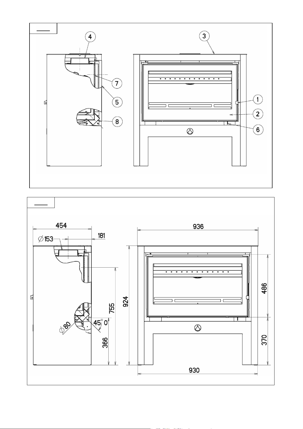
Fig. 1
Fig. 2
59
Page 60

Fig. 3a
Fig. 3b
60
Page 61

Fig. 4
61
Page 62

1 2 3 4
Fig. 5
A B
Fig. 7
Fig. 8
Fig. 6
Fig. 9
F GB D NL I E P
Position allure
1
mini
Position allure
2
intermédiaire
Position allure
3
maxi
Position allumage Lighting position Position Anzünden Positie
4
Minimum heat
position
Intermediate heat
position
Maximum heat
position
Position minimale
Geschwindigkeit
Position mittlere
Geschwindigkeit
Position maximale
Geschwindigkeit
Positie ministand Posizione
Positie
intermediaire
stand
Positie
maxistand
aansteken
andatura minima
Posizione
andatura
intermedia
Posizione
andatura
massima
Posizione
accensione
Posición
velocidad mínima
Posición
velocidad
intermedia
Posición
velocidad máxima
Posición
encendida
Posição
velocidade
mínima
Posição
velocidade
intermédia
Posição
velocidade
máxima
Posição
Acendimento
62
Page 63

14/10 mm
Fig. 10
Fig. 11
2
Fig. 12
3 vis
3 screws
3 Schrauben
3 vite
3 tornillos
3 parafusos
Fig. 13
63
Page 64

Les descriptions et caractéristiques figurant sur ce document sont données à titre d'information et non d'engagement. En effet,
soucieux de la qualité de nos produits, nous nous réservons le droit, d'effectuer, sans préavis, toute modification ou amélioration.
* * *
Société Anonyme au capital de 6.404.454 €
R.C SEDAN 787 020 080 B - Sirène 787 020 080 00018
SIEGE SOCIAL
76 rue Forest - 08013 CHARLEVILLE-MEZIERES CEDEX
www.deville.fr
-
contact@deville.fr
64
 Loading...