

Page 1
N° P0050776.0
9
07/10
F
NOTICE D’INSTALLATION POELE A BOIS 2 - 5
GB
WOOD STOVE INSTALLATION MANUAL 6 - 9
D
ANLEITUNG ZUR INSTALLATION EINES OFFENS
FUR HOLZFEUERUNG 10 - 13
I
ISTRUZIONI PER L’INSTALLAZIONE STUFA A LEGNA 14 - 17
E
MANUAL DE INSTRUCCIONES ESTUFA DE LEÑA 18 - 21
P
MANUAL DE INSTALAÇÃO FOGÃO A LENHA 22 - 25
Page 2
F
Nous vous conseillons de lire attentivement, et au complet, le texte de la notice afin de tirer le meilleur usage et la
plus grande satisfaction de votre appareil DEVILLE.
Le non-respect des instructions de montage, d’installation et d’utilisation entraîne la responsabilité de celui qui
les effectue.
CET APPAREIL DOIT ETRE INSTALLE CONFORMEMENT AUX SPECIFICATIONS DES D.T.U. EN
VIGUEUR.
Toutes les réglementations locales et nationales, ainsi que les normes européennes, doivent être
respectées lors de l’utilisation de l’appareil.
L’appareil ne doit pas être modifié.
L’INSTALLATION PAR UN PROFESSIONNEL QUALIFIE EST RECOMMANDEE.
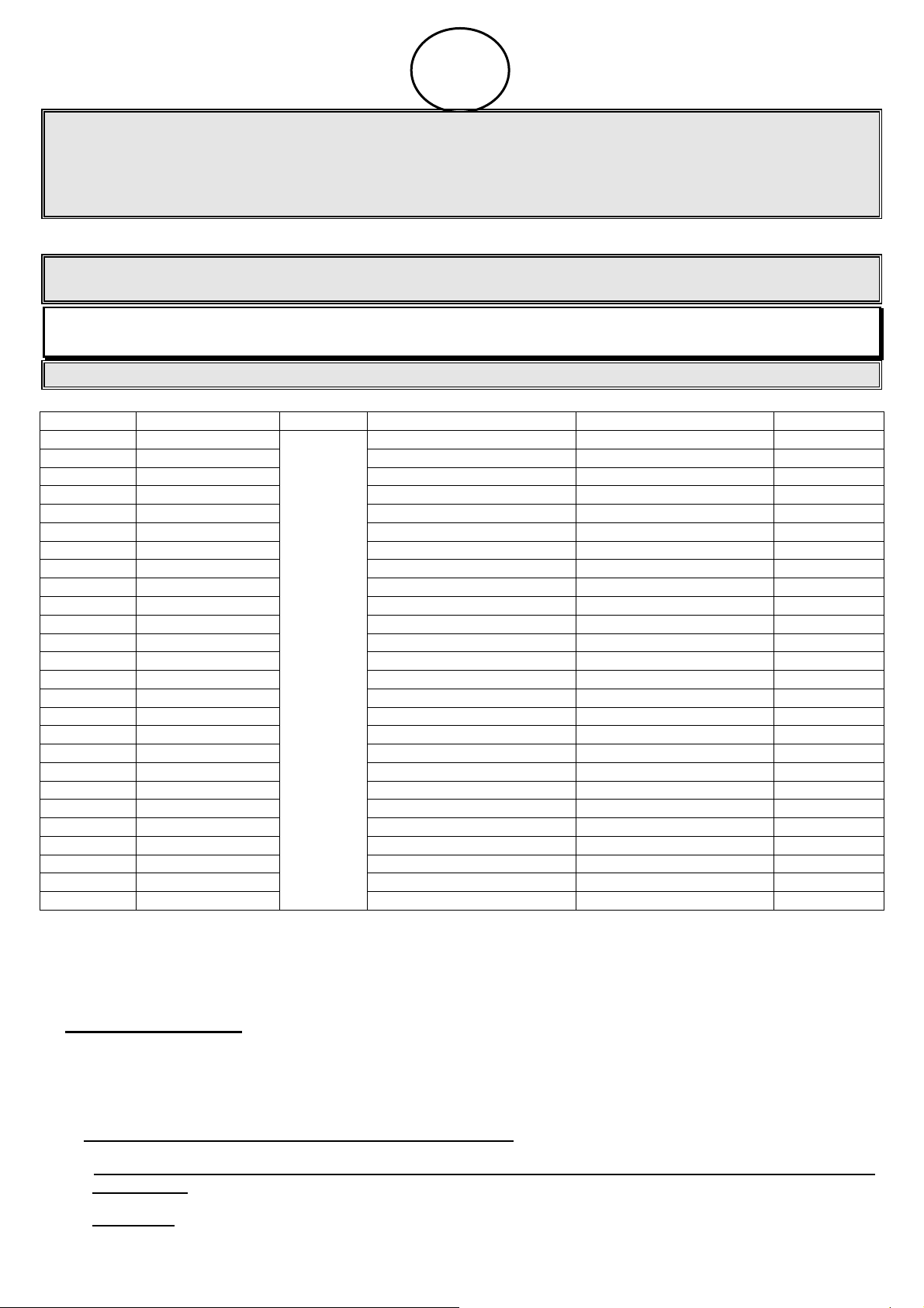
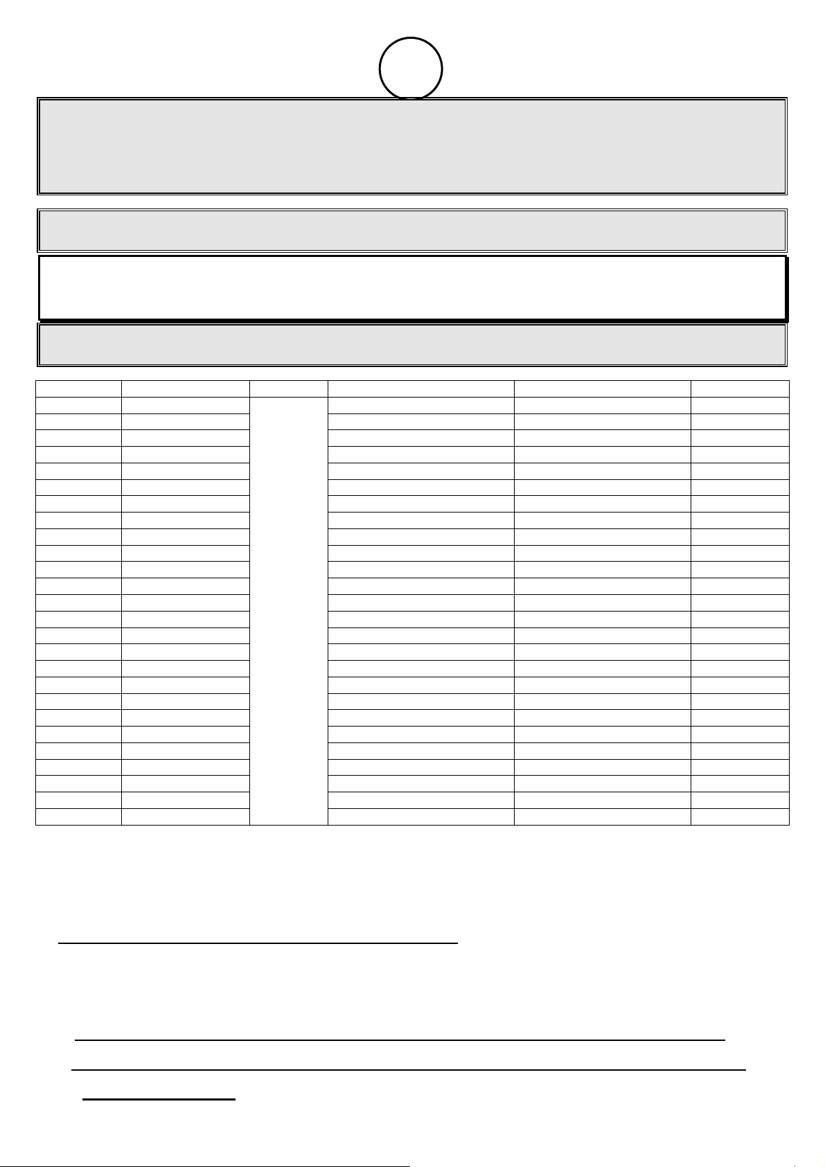
Référence Puissance nominale Tirage Débit massique des fumées
C07706 9 KW 6,5 g/s 306 °C 136 kg
C07708 9 KW 6,1 g/s 270 °C 87 kg
C07709 9 KW 6,1 g/s 270 °C 101 kg
C07726 9 KW 6,5 g/s 306 °C 143 kg
C07727 9 KW 6,5 g/s 306 °C 156 kg
C07728 12 KW 9,2 g/s 353 °C 171 kg
C07729 9 KW 6,5 g/s 306 °C 155 kg
C07750 9 KW 6,1 g/s 270 °C 95 kg
C07751 7 KW 6,2 g/s 288 °C 54 kg
C07753 14 KW 8,2 g/s 295 °C 130 kg
C07762 9 KW 6,1 g/s 270 °C 71 kg
C07780 13 KW 10,6 g/s 305 °C 114 kg
C07782 9 KW 6,1 g/s 270 °C 104 kg
C07783 14 KW 8,2 g/s 295 °C 113 kg
C07784 14 KW 8,2 g/s 295 °C 130 kg
C07785 9 KW 6,1 g/s 270 °C 100 kg
C07787 9 KW 6 g/s 310 °C 94 kg
C07788 9 KW 6 g/s 310 °C 100 kg
C07789 9 KW 6,1 g/s 270 °C 84 kg
C07790 9 KW 6,1 g/s 270 °C 91 kg
C07794 11 KW 8,1 g/s 306 °C 120 kg
C07794-FP 9 KW 7.5 g/s 319 °C 118 kg
C07796 11 KW 8,1 g/s 306 °C 156 kg
C07796-FP 9 KW 7.5 g/s 319 °C 154 kg
C07799 9 KW 6,1 g/s 270 °C 73 kg
C077AA 9 KW
Ces poêles sont conformes aux exigences essentielles de la directive 89/106/CEE Produits de Construction suivant
l’annexe ZA de la norme EN 13240.
Ce sont des appareils de chauffage continu à combustion sur grille fonctionnant exclusivement au bois, à chambre de
combustion semi fermée.
1. CONDITIONS D’INSTALLATION DE L’APPAREIL
L'installation ne devra pas être modifiée par l'utilisateur.
Nous rappelons ci-après les recommandations élémentaires à respecter. Le DTU 24-2-2 décrit de façon complète les
dispositions nécessaires concernant le circuit d’évacuation des fumées.
1.1 - DöNOMINATION DES DIVERSES PARTIES DU CIRCUIT D'öVACUATION DES FUMöES (Fig. 1)
1.2 - NATURE ET CARACTöRISTIQUES DIMENSIONNELLES DU CONDUIT DE FUMöE AUQUEL DOIT ÊTRE
OBLIGATOIREMENT RACCORDö L'APPAREIL
1.2.1 Nature du conduit de fumée
12 Pa
6,1 g/s 270 °C 78 kg
Température des fumées Poids net
2
Page 3
1.2.1.1 Cas d'un conduit neuf
Utilisation des matériaux suivants
:
. Boisseaux de terre cuite conformes à la NF P 51-311.
. Boisseaux en béton conformes à la NF P 51-321.
. Conduits métalliques composites conformes aux NF D 35-304 et NF D 35-303.
. Briques en terre cuite conformes à la NF P 51-301.
. Briques réfractaires conformes à la NF P 51-302.
L'utilisation de matériaux isolés d'origine permet d'éviter la mise en place d'une isolation sur le chantier, notamment au
niveau des parois de la souche.
1.2.1.2 Cas d'un conduit existant
L'installateur prend à son compte la responsabilité des parties existantes. Il doit vérifier l'état du conduit et y apporter les
aménagements nécessaires pour son bon fonctionnement et la mise en conformité avec la réglementation.
Ramoner le conduit puis procéder à un examen sérieux pour vérifier :
. la compatibilité du conduit avec son utilisation
. la stabilité
. la vacuité et l’étanchéite (annexe II du DTU 24-1).
Si le conduit n'est pas compatible, réaliser un tubage à l'aide d'un procédé titulaire d'un Avis Technique favorable ou
mettre en place un nouveau conduit.
1.2.2 Section minimale du conduit
Boisseaux carrées ou rectangulaires : section minimale 2,5 dm2.
Conduits circulaires : diamètre minimal 153 mm.
1.2.3 Quelques préconisations générales
Un bon conduit doit être construit en matériaux peu conducteurs de la chaleur pour qu'il puisse rester chaud. L'habillage
du conduit doit permettre de limiter la température superficielle extérieure à :
. 50 °C, dans les parties habitables,
. 80 °C, dans les parties non habitables ou inaccessibles.
Il doit être absolument étanche, sans rugosité et stable.
Il ne doit pas comporter de variations de section brusques : pente par rapport à la verticale inférieure à 45°.
Il doit déboucher à 0,4 m au moins au-dessus du faîte du toit et des toits voisins.
Deux appareils ne doivent pas être raccordés sur un même conduit.
Il doit déboucher dans la pièce où sera installé le foyer, sur une hauteur d'au moins 50 mm.
Sa face intérieure doit être éloignée de 16 cm au moins de tout bois et matière combustible.
Les boisseaux doivent être montés partie mâle vers le bas afin d'éviter le passage des coulures à l'extérieur.
Le conduit ne doit pas comporter plus de deux dévoiements (c'est à dire plus d'une partie non verticale).
Si c'est un conduit maçonné :
. L'angle des dévoiements ne doit pas excéder 45° pour une hauteur totale du conduit limitée à 5 m. Pour une hauteur
supérieure, l'angle de dévoiement est limité à 20°.
Si c'est un conduit métallique isolé :
. L'angle des dévoiements ne doit pas excéder 45° avec une limitation de hauteur de 5 m entre le haut et le bas du
dévoiement. La hauteur totale du conduit n'est pas limitée.
L'étanchéité, l'isolation, les traversées de plafond et plancher, les écarts au feu doivent être réalisés dans le strict respect
du DTU 24-2-2.
1.3 - NATURE ET CARACTöRISTIQUES DU CONDUIT DE RACCORDEMENT ENTRE L’APPAREIL ET LE CONDUIT
DE FUMöE
Un conduit de raccordement doit être installé entre l'appareil et le débouché du conduit de fumée. Ce conduit doit être
réalisé à l'aide d'un tubage polycombustible rigide ou flexible, justifiable d'un Avis Technique favorable pour une desserte
directe de foyer fermé.
3
Page 4
A noter que sont interdits
: l'aluminium, l'acier aluminié et l'acier galvanisé.
A noter que sont autorisés : la tôle noire (ép. Mini 2 mm), la tôle émaillée (ép. Mini 0,6 mm), l'acier inoxydable (ép. Mini
0,4 mm).
Ce conduit doit être visible sur tout son parcours et ramonable de façon mécanique. Sa dilatation ne doit pas nuire à
l'étanchéité des jonctions amont et aval ainsi qu'à sa bonne tenue mécanique et à celle du conduit de fumée. Sa
conception et, en particulier, le raccordement avec le conduit de fumée doit empêcher l'accumulation de suie,
notamment au moment du ramonage.
Les jonctions avec l'appareil d'une part et le conduit de fumée d'autre part doivent être réalisées dans le strict respect du
DTU 24-2-2 et des spécifications du constructeur du tube, en utilisant tous les composants préconisés (embouts,
raccords, etc...).
Dans le cas où le conduit de raccordement est horizontal, une pente ascendante de 5 cm par mètre doit exister.
1.4 - CONDITIONS DE TIRAGE
Le tirage est mesuré sur le conduit de raccordement à environ 50 cm après la buse de l'appareil.
Tirage nécessaire au bon fonctionnement porte fermée :
. 6 Pa en allure réduite (0,6 mm de CE).
. 12 Pa en allure normale (1,2 mm de CE).
La mise en place d’un modérateur de tirage est vivement recommandée.
Le modérateur permet d’obtenir un bon fonctionnement, même dans des conditions de tirage importantes (conduits
hauts, tubage). Le modérateur doit être facilement visible et accessible (Fig. 2) et installé dans la pièce où se trouve
l’appareil.
Le volet modérateur de tirage n'a pas d'influence sur le fonctionnement de l'appareil lorsque la porte est ouverte.
1.5 - VENTILATION DU LOCAL OÙ L'APPAREIL EST INSTALLö
Le fonctionnement de l'appareil nécessite un apport d'air supplémentaire à celui nécessaire au renouvellement d'air
réglementaire. Cette amenée d'air est obligatoire lorsque l'habitation est équipée d'une ventilation mécanique.
La prise d'amenée d'air doit être située soit directement à l'extérieur, soit dans un local ventilé sur l'extérieur, et être
protégée par une grille.
La sortie d'amenée d'air doit être située le plus près possible de l'appareil. Elle doit être obturable lorsqu'elle
débouche directement dans la pièce. Pendant le fonctionnement de l’appareil, s’assurer qu’elle soit libre de
toute obstruction.
La section d'entrée d'air doit être au minimum égale au quart de la section du conduit de fumée avec un minimum de 50
cm² pour une puissance nominale inférieure ou égale à 8 KW, et 70 cm² pour une puissance nominale entre 8 KW et 16
KW.
Il peut être nécessaire de stopper l'extracteur de la ventilation mécanique pour éviter le refoulement des fumées dans la
pièce lors de l'ouverture de la porte.
1.6 - NATURE DES MURS ET DES PAROIS AVOISINANT L'APPAREIL
Placer le poêle à la distance minimale de 300 mm des murs arrières et latéraux de l’habitation et de tous matériaux
combustibles.
Pour protéger le sol contre le rayonnement de chaleur, et la chute éventuelle de combustible poser l’appareil sur un
écran métallique réfléchissant (ou un sol carrelé) couvrant toute la surface du sol située sous et devant l’appareil.
L’appareil doit être installé sur un sol avec une capacité portante suffisante. Si une construction existante ne satisfait pas
à cette condition préalable, des mesures adéquates (par exemple, l’installation d’une plaque de répartition de charge)
doivent être prises pour permettre au sol de supporter l’appareil.
4
Page 5
1.7 - CONDITIONS GENERALES DE GARANTIE
1. MODALITES
En dehors de la garantie légale, à raison des vices cachés, DEVILLE garantit le matériel en cas de vices apparents
ou de non-conformité du matériel livré au matériel commandé.
Sans préjudice des dispositions à prendre vis-à-vis du transporteur, les réclamations lors de la réception du matériel
sur les vices apparents ou la non-conformité, doivent être formulées auprès de DEVILLE par l’acheteur dans les cinq
jours de la constatation du vice par voie de lettre recommandée avec demande d’avis de réception. Il appartient à
l’acheteur de fournir toute justification quant à la réalité des vices ou des anomalies constatées. L’acheteur doit, par
ailleurs, laisser à DEVILLE toute facilité pour procéder à la constatation de ces vices ou anomalies et pour y porter
remède. De même l’acheteur doit tenir les matériels non conformes à la disposition de DEVILLE, selon les
instructions de cette dernière. Tout retour du matériel, pour quelque raison que ce soit, doit faire l’objet d’un accord
préalable formel de DEVILLE.
2. ETENDUE
La garantie de DEVILLE couvre, à l’exclusion de toute indemnité ou dommages-intérêts, le remplacement gratuit ou
la réparation du matériel ou de l’élément reconnu défectueux (hors pièces d’usure) par ses services à l’exclusion des
frais de main-d’œuvre, de déplacement et de transport.
Sur les appareils émaillés, les craquelures ne sont jamais considérées comme un défaut de fabrication. Elles sont la
conséquence de différence de dilatation tôle-émail ou fonte-émail et ne modifient pas l’adhérence. Les pièces de
rechange fournies à titre onéreux sont garanties six mois à partir de la date de facture ; toute garantie
complémentaire consentie par un revendeur de DEVILLE n’engage pas DEVILLE. La présentation du certificat de
garantie portant le cachet à date du revendeur DEVILLE est rigoureusement exigée lorsque la garantie est invoquée.
Ce certificat doit être présenté lors de la demande de réparation de l’appareil sous garantie, ou bien un talon ou un
volet détachable de ce certificat doit, selon l’organisation propre à DEVILLE, être retourné à celle-ci dans les délais
impartis. A défaut, la date figurant sur la facture émise par DEVILLE ne peut être prise en considération. Les
interventions au titre de la garantie ne peuvent avoir pour effet de prolonger celle-ci.
3. DUREE
La durée de la garantie contractuelle assurée par DEVILLE est de 2 ans (5 ans pour le corps de chauffe
foyers/inserts) à compter de la date d’achat de l’appareil par l’usager, sous réserve que les réclamations prévues au
titre des modalités ci-dessus aient été formulées dans les délais impartis. La réparation, le remplacement ou la
modification de pièces pendant la période de garantie ne peut avoir pour effet de prolonger la durée de celle-ci, ni de
donner lieu en aucun cas à indemnité pour frais divers, retard de livraison, accidents ou préjudices quelconques.
4. EXCLUSION
La garantie ne s’applique pas dans les cas suivants, sans que cette liste soit exhaustive :
Installation et montage des appareils dont la charge n’incombe pas à DEVILLE. En conséquence, DEVILLE ne peut
être tenue pour responsable des dégâts matériels ou des accidents de personne consécutifs à une installation non
conforme aux dispositions légales et réglementaires (par exemple l’absence de raccordement à une prise de terre ;
mauvais tirage d’une installation) ;
Usure normale du matériel ou utilisation ou usage anormal du matériel, notamment en cas d’utilisation industrielle ou
commerciale ou emploi du matériel dans des conditions différentes de celles pour lesquelles il a été construit. C’est
le cas par exemple du non-respect des conditions prescrites dans la notice DEVILLE : exposition à des conditions
extérieures affectant l’appareil telles qu’une humidité excessive ou variation anormale de la tension électrique ;
Anomalie, détérioration ou accident provenant de choc, chute, négligence, défaut de surveillance ou d’entretien de
l’acheteur ;
Modification, transformation ou intervention effectuée par un personnel ou une entreprise non agréée par DEVILLE
ou réalisée avec des pièces de rechange non d’origine ou non agréées par le constructeur.
5. CONDITIONS PARTICULIERES DE GARANTIE
Ces conditions complètent et précisent les conditions générales de garanties ci-dessus et ont primauté sur celles-ci,
se reporter au feuillet ci joint « Conditions particulières de vente DEVILLE – Garantie ».
5
Page 6
GB
You are advised to read carefully and in full the information provided in order to get the best performance - and
the most satisfaction - out of your DEVILLE stove.
Failure to comply with the assembly, installation and operating instructions places all responsibility upon the
person(s) concerned.
INSTALLATION SHOULD COMPLY WITH CURRENT DTU (FRENCH CODE OF PRATICE)
SPECIFICATIONS.
All local, national, and european regulations must be respected when using this appliance.
The appliance must not be modified.
INSTALLATION BY A QUALIFIED TRADESMAN IS RECOMMENDED.
Reference Power rating Draft
C07706 9 KW 6,5 g/s 306 °C 136 kg
C07708 9 KW 6,1 g/s 270 °C 87 kg
C07709 9 KW 6,1 g/s 270 °C 101 kg
C07726 9 KW 6,5 g/s 306 °C 143 kg
C07727 9 KW 6,5 g/s 306 °C 156 kg
C07728 12 KW 9,2 g/s 353 °C 171 kg
C07729 9 KW 6,5 g/s 306 °C 155 kg
C07750 9 KW 6,1 g/s 270 °C 95 kg
C07751 7 KW 6,2 g/s 288 °C 54 kg
C07753 14 KW 8,2 g/s 295 °C 130 kg
C07762 9 KW 6,1 g/s 270 °C 71 kg
C07780 13 KW 10,6 g/s 305 °C 114 kg
C07782 9 KW 6,1 g/s 270 °C 104 kg
C07783 14 KW 8,2 g/s 295 °C 113 kg
C07784 14 KW 8,2 g/s 295 °C 130 kg
C07785 9 KW 6,1 g/s 270 °C 100 kg
C07787 9 KW 6 g/s 310 °C 94 kg
C07788 9 KW 6 g/s 310 °C 100 kg
C07789 9 KW 6,1 g/s 270 °C 84 kg
C07790 9 KW 6,1 g/s 270 °C 91 kg
C07794 11 KW 8,1 g/s 306 °C 120 kg
C07794-FP
C07796 11 KW 8,1 g/s 306 °C 156 kg
C07796-FP
C07799 9 KW 6,1 g/s 270 °C 73 kg
C077AA 9 KW
These wood stoves comply with the essential requirements of the directive 89/106/CEE Construction Products
according to appendix ZA of the standard EN 13240.
These are constant heating system with grating combustion designed exclusively for wood burning, inside a semi-closed
combustion chamber.
1. GENERAL CONDITIONS
The user should not make any modifications to this appliance.
Basic recommendations are given below. DTU 24-2-2 describes in detail the procedures required regarding the smoke
venting circuit.
1.1 - DIAGRAM SHOWING SMOKE FLUE COMPONENTS (Fig. 1)
1.2 - CHARACTERISTICS AND DIMENSIONS OF SMOKE FLUE TO WHICH CONNECTION OF THE STOVE IS
MANDATORY
1.2.1 Smoke flue
9 KW 7.5 g/s 319 °C 118 kg
9 KW 7.5 g/s 319 °C 154 kg
12 Pa
Mass discharge of smoke Temperature of smoke Net weight
6,1 g/s 270 °C 78 kg
6
Page 7
1.2.1.1 New flue
The following materials must be used :
. Fireclay flue liners compliant with French Standard NF P 51-311.
. Concrete flue liners compliant with NF P 51-321.
. Composite metal ducts compliant with NF D 35-304 and NF D 35-303.
. Fireclay bricks compliant with NF P 51-301.
. Refractory bricks compliant with NF P 51-302.
Using already insulated materials avoids having to insulate during installation, which is especially useful where stacks
linings are concerned.
1.2.1.2 Existing flue
Whoever is doing the installation is responsible for existing work, and therefore should check the flue and carry out any
work required to ensure it is in proper working order and that it complies with current regulations.
Sweep the flue and then thoroughly inspect it to check the following :
. the flue’s suitability for its intented use
. stability
. lack of any obstruction and absence of leaks (DTU 24-1, Appendix II).
If the flue is not compatible with the stove, install the required tubing using an approved and certificated method (in
France, a method that has an “Avis Technique” certificate), or else put in a new flue.
1.2.2 Minimum flue section
Square or oblong liners : minimum section 2,5 dm
2
Circular ducts : mimimum diameter 153 mm.
1.2.3 General recommendations
A good flue should be built using materials that do not conduct much heat so that it stays hot. The casing should be such
as to limit the external surface temperature as follows :
. 50°C in living areas
. 80°C in non-living.
The flue should be completely smoketight, smooth and stable.
There should be no sudden variations in section : angle in relation to the vertical should be less than 45°.
The stake should extend at least 0,4 m from the ridge of the roof and adjacent roofs.
Two stoves should not be connected to the same flue.
Where the stove itself is installed, the flue should come down to at least 50 mm above floor level.
The inside face should be at least 16 cm away from any wood or combustible material.
The flue liners should be placed the male part down, in order to avoid runs to the outer surface.
The flue should include no more than two changes in alignment (i.e. not more than one non-vertical section).
Flue cased in brickwork :
. No angle of change of alignment should exceed 45° over a total flue height not exceeding 5 metres. For any greater
flue height, the angle of any change of alignment is limited to 20°.
Insulated metal flue :
. No angle of change of alignment should exceed 45° and height form top to bottom of any such angled section should
not exceed 5 metres. Total flue height is unrestricted.
Smoketightness, insulation, runs through ceilings and floors and safe distances to flue should be in strict compliance with
DTU 24-2-2.
1.3 - CHARACTERISTICS OF CONNECTOR FITTING BETWEEN STOVE AND FLUE
First, it is essential to install a connector between the stove and the flue. The connector should use rigid or flexible
multifuel conduit approved for direct connection to a closed source of heat.
7
Page 8
The following materials are prohibited
: aluminium, aluminized and galvanized steel.
The following materials are approved : black plate (min. thickness 2 mm), enamelled plate (min. thickness 0.6 mm) and
stainless steel (min. thickness 0.4 mm).
The connector fitting should be visible over its entire length and capable of being swep mechanically. Expansion should
not adversely affect the conduit intake or discharge junctions or its own mechanical stability or that of the main smoke
flue. Its design, and more especially its connection to the smoke flue, should be such as to prevent the accumulation of
soot, notably during sweeping.
Connections to both the stove and the flue should strictly comply with DTU 24.2.2 and the conduit manufacturer's
specifications and should include all the fittings recommended (end fittings, connecting pieces etc...).
If the connector is to be horizontal, there should be an ascending slope of 5 cm per metre.
1.4 - DRAUGHT REQUIREMENTS
Draught is measured on the connector duct about 50 cm after the stove outlet.
The draught required for efficient working with the door closed is as follow :
. 6 Pa on slow (0,6 mm WG)
. 12 Pa on normal (1,2 mm WG)
The installation of a damper is strongly recommended.
A damper ensures an efficient operation, even where draught requirements are considerable (high flue and casing). The
damper should be visible and readily accessible (Fig. 2) and installed in the same room as the stove.
The damper does not habe any effect on the stove when the door is open.
1.5 - VENTILATION OF AREA IN WHICH STOVE IS INSTALLED
To ensure the stove works properly, air is required in addition to the air required for the statutory ventilation rate. This
additional air is compulsory when the dwelling is equipped with a mechanical ventilation system.
The air intake should be positioned either directly to the outside or in an area having ventilation to the outside. The intake
should be equipped with a protective grill.
The air outlet should be as near as possible to the stove. The user should be able to close it off when it comes
out directly into the room. While the appliance is being used, make sure that it is free of any obstructions.
The section of the air inlet must be at least equal to one quarter of the section of the chimney flue with a minimum of 50
cm² for a power rating less than or equal to 8 kW, and 70 cm² for a power rating between 8 KW and 16 KW.
It may be necessary to stop the mechanical ventilation fan so as to prevent smoke coming back into the room when the
door is opened.
1.6 – WALLS IN THE VICINITY OF THE APPLIANCE
The stove should be located at least 300 mm from the rear and side walls of the room and from any combustible
materials.
In order to protect the floor from heat radiation and possible falling combustible, install the unit on reflective metal
shielding (or on a tiled floor) which covers the entire surface underneath and in front of the unit.
The appliance must be set up on a floor with a sufficient bearing capacity. If the existing construction does not comply
with this prior requirement, appropriate measures must be taken to allow the floor to bear the appliance, such as setting
up a load distribution plate.
8
Page 9
1.7 - GLOBAL TERMS OF WARRANTY
1. TERMS AND CONDITIONS
Apart from the legal warranty, particularly for latent defects, Deville guarantees to deliver the furniture in case of
obvious defects or non-conformity to the ordered furniture.
Without prejudice to the provisions that are to be taken concerning the carrier, claims on delivery of furniture
concerning the obvious defects or the non conformity, must be issued by the Buyer in writing a registered letter with
confirmation of receipt to Deville company with in 5 days after noticing the defect. It is up to the Buyer to prove the
reality of the noticed defects and irregularities. The Buyer must let Deville every opportunity of noticing any of those
defects and irregularities in order to salve then.
The Buyer must also keep the non standard supplies at the disposal of Deville, according to the instructions of the
latter. All return of material, for any reasons, should be subject to a formal pre – agreement from Deville.
2. EXTEND
The warranty of Deville covers, except for any compensation or for damages, the free replacement or repairing of
supplier the part acknowledged as being defected (except for wear and tear parts ) by its services to the exclusion of
the fees for the workplace, for the removal and for the shipping.
On enamelled equipments, appliances, crackles are never considered as a manufacturing defect. They are due to
the difference of expansion of iron enamel or cast-iron enamel and don’t alter the adherence.
Paid replacement parts are warranted for a six-month period from the invoicing date, any additional warranty agreed
by a retailer from Deville doesn’t commit Deville. Whenever claiming under a warranty, the guarantee with the stamp
from the retailer Deville is strictly required. The above guarantee must be produced for any demand to repair the
appliance under warranty, or a detachable slip or coupon of any such guarantee must, according to the own
organisation of Deville, be returned to the latter within the required time. For lack of this, the date on the invoice
issued by Deville can’t be taken into account. The interventions under warranty can’t have the effect of continuing the
warranty.
3. WARRANTY PERIOD
The period of the agreed warranty ensured by Deville is for 2 years (5 years for the fireplace heating body) from the
date when the appliance was purchased by the user, subject to the fact the claims -forecast by the above conditionswere done within the time allowed. The repairing, the replacement or the alteration of parts under the warranty period
can neither have the effect of continuing the period of the latter, not get to any compensation for any fees, for late
delivery, accidents or any such damages.
4. EXCLUSION
The warranty is unavailable for the following cases, without this list being exhaustive :
Fitting out, fitting out and assembling of appliances not due to Deville.
Consequently Deville can’t be considered as responsible for damages or supplies, or accidents to persons due to
local laws and regulations (for example the fact that there is no linking to the earth ground connection or a wrong
drought of a fitting out).
Fair wear and tear of the supplies or abnormal use of the supplies including the case of industrial or trading use or a
use of the supplies in different conditions from the ones it was built for. It is, for example, of non respect of the
conditions described in the directions issued by Deville : display to outside conditions damaging the appliance ; such
as excessive dampness or abnormal change of the electrical tension. Malfunction, damage or accident due to a
shock, a drop, a carelessness, a failure of supervision or of service from the Buyer.
Any alteration, change or intervention made by a member of the staff or a company that is not approved by Deville,
or manufactured with replacement parts that are not genuine or not approved by the manufacturer.
5. SPECIAL TERMS OF WARRANTY
These terms add and define the above general terms of warranty and come first to the former, refer to the enclosed
leaf untitled : “special terms of sales Deville - warranty”.
9
Page 10
D
Zur optimalen und zufriedenstellenden Nutzung Ihres Deville-Feuerraum-Einsatzes empfehlen wir Ihnen, die
vorliegende Anleitung in ihrer Gesamtheit vollständig durchzulesen.
Personen, welche die Richtlinien fûr Montage, Installation und Verwendung nicht beachten, sind für eventuelle
Folgen selbst verantwortlich.
DER OFEN MUSS UNTER BEACHTUNG GELTENDER TECHNISCHER VORSCHRIFTEN INSTALLIERT
WERDEN.
Alle örtlichen und nationalen vorschriften sowie die europäischen Normen müssen bei der Benutzung
des Gerätes beachtet werden.
Das Gerät darf nicht verandert werden.
ES WIRD EMPFOHLEN, DIE INSTALLATION DURCH EINE FACHKRAFT DURCHFUHREN ZU
Referenzen
C07706 9 KW 6,5 g/s 306 °C 136 kg
C07708 9 KW 6,1 g/s 270 °C 87 kg
C07709 9 KW 6,1 g/s 270 °C 101 kg
C07726 9 KW 6,5 g/s 306 °C 143 kg
C07727 9 KW 6,5 g/s 306 °C 156 kg
C07728 12 KW 9,2 g/s 353 °C 171 kg
C07729 9 KW 6,5 g/s 306 °C 155 kg
C07750 9 KW 6,1 g/s 270 °C 95 kg
C07751 7 KW 6,2 g/s 288 °C 54 kg
C07753 14 KW 8,2 g/s 295 °C 130 kg
C07762 9 KW 6,1 g/s 270 °C 71 kg
C07780 13 KW 10,6 g/s 305 °C 114 kg
C07782 9 KW 6,1 g/s 270 °C 104 kg
C07783 14 KW 8,2 g/s 295 °C 113 kg
C07784 14 KW 8,2 g/s 295 °C 130 kg
C07785 9 KW 6,1 g/s 270 °C 100 kg
C07787 9 KW 6 g/s 310 °C 94 kg
C07788 9 KW 6 g/s 310 °C 100 kg
C07789 9 KW 6,1 g/s 270 °C 84 kg
C07790 9 KW 6,1 g/s 270 °C 91 kg
C07794 11 KW 8,1 g/s 306 °C 120 kg
C07794-FP
C07796 11 KW 8,1 g/s 306 °C 156 kg
C07796-FP
C07799 9 KW 6,1 g/s 270 °C 73 kg
C077AA 9 KW
Diese Öfen sind den wesentlichen Forderungen der Direktive 89 / 106 / CEE vom der Nebengebäude ZA der Norm EN
13240 folgenden Bau Hergestellt entsprechend.
Es sind handelt sich um ein Heizgerät, das im Dauerbetrieb auf Rost ausschließlich mit Holz, bei halb-geöffnetem
Brennraum beschickt wird.
1. VORAUSSETZUNGEN FUR DIE INSTALLATION DES OFFENS
Die Installation darf vom Benutzer nicht abgeändert werden.
Wir stellen nachfolgend die grundlegenden, bei der Installation einzuhaltenden Empfehlungen zusammen. Die
technische Vorschrift DTU 24-2-2 beschreibt vollständig alle notwendigen Vorrichtungen zur Abführung von Rauchgasen.
1.1 - BEZEICHNUNG DER VERSCHIEDENEN TEILE EINES RAUCHGAS-ABFUHRUNGSSYSTEMS (Abb. 1)
1.2 - ART UND ABMESSUNGEN DES KAMINSCHACHTS, AN DEM DER OFFEN ANGESCHLOSSEN WERDEN MUSS
1.2.1 Art des Kaminschachts
Leistung Zug
12 Pa
9 KW 7.5 g/s 319 °C 118 kg
9 KW 7.5 g/s 319 °C 154 kg
LASSEN.
Rauchmassenstrom Rauchtemperatur Nettogewicht
6,1 g/s 270 °C 78 kg
10
Page 11
1.2.1.1 Fall eines neuen kaminschachts
Verwendung folgender Materialien :
. Kaminbauformsteine aus gebranntem Ton gemäß NF P 51-311.
. Kaminbauformsteine aus Beton gemäß NF P 51-321.
. Metallene Verbundrohre gemäß NF D 35-304 und NF D 35-303.
. Gebrannte Tonsteine gemäß NF P 51-301.
. Feuerfeste Steine gemäß NF P 51-302.
Durch Verwendung bereits isoliert vorgefertigter Teile wird der Einbau einer Isolierung auf der Baustelle, insbesondere
für die Wände Schornsteinkastens, vermieden.
1.2.1.2 Fall eines existierenden Kaminschachts
Der Installateur übernimmt die Verantwortung für die vorhandenen Teile : Er muß den Zustand des Kaminschachts
überprüfen und die für den richtigen Betrieb und die Einhaltung der bestehenden Vorschriften notwendigen Arbeiten
durchführen.
Den Kaminschacht fegen und dann im Rahmen einer ernsthaften Überprüfung folgendes sicherstellen :
. Eignung des Kaminschachts für die vorgesehene Benutzung,
. Stabilität,
. Abwesenheit von Fremdkörpern und Dichtigkeit (Anhang II der technischen Vorschrift DTU 24-1).
Falls der Kaminschacht nicht kompatibel ist, gemäß einem technisch zugelassenen Verfahren in dessen Innern eine
Rohrleitung einführen oder einen neuen Schornstein errichten.
1.2.2 Mindestquerschnitt des Kaminschachts
Quadratische oder rechteckige Kaminformbausteine : Mindestquerschnitt 2,5 dm2.
Kreisförmige Rohre : Mindestdurchmesser 153 mm.
1.2.3 Einige allgemeine Empfehlungen
Ein guter Kamlnschacht muß, um seine Wärme beibehalten zu können, aus schwach wärmeleitenden Materialien gebaut
sein. Die Verkleidung des Schachts muß eine Begrenzung der äußeren Oberflächentemperatur auf folgende Werte
ermöglichen :
. 50°C in den bewohnbaren Bereichen
. 80°C in nichtbewohnbaren oder unzugänglichen Ber eichen.
Ein kaminschacht muß vollkommen dicht, glatt und stabil sein.
Er darf keine abrupten Querschnittsswankungen aufweisen. Er muß um weniger als 45° Senkrechten geneigt sein.
Seine Ausgangsöffnung muß mindestens 0,4 m oberhalb des Dachfirsts und der benachbarten Dächer liegen.
Zwei Ofen dürfen nicht am gleichen Kamineinsatz angeschlossen werden.
Seine Ausgangöffnung im Raum, in dem der Ofen installiert wird, muß mindestens 50 mm oberhalb des Bodens
gelegen.
Seine Innenfläche muß mindestens 16 cm von Holz oder anderen brennbaren Materialien entfernt sein.
Die Kaminbauformsteine müssen mit der vorstehenden Seite nach unten und der vertieften Seite nach oben
zusammengesetzt werden, um sicherzustellen, daß nichts nach außen abfließen kann.
Der Kaminschacht darf nicht mehr als zwei Ablenkungen (nur einen nicht senkrechten Abschnitt) aufweisen.
Bei gemauertem Kaminschacht :
. Der Winkel von Neigungen darf bei einer Gesamthöhe des Kamins von 5 m nicht 45° übertreffen. Bei Ka minen
größerer Höhe als 5 m ist der Winkel von Neigungen auf 20° begrenzt.
Bei isoliertem Metallrohr :
. Der Winkel von Neigungen darf 45° nicht übertref fen, wobei die Höhe zwischen der unteren und der oberen
Ablenkungsstelle nicht länger als 5 m sein darf. Die Gesamthöhe des Rohrs ist unbegrenzt.
Alle Arbeiten, die sich auf Abdichtung, Isolierung, Durchführungen durch Böden und Decken, sowie BrandschutzSicherheitsabstände beziehen, müssen unter strenger Einhaltung der technischen Vorschriften DTU 24.2.2 durchgeführt
werden.
11
Page 12

1.3 - ART UND EIGENSCHAFTEN DER ANSCHLUSSVERBINDUNG ZWISCHEN OFEN UND KAMINSCHACHT
Zwischen dem Ofen und dem Kaminschacht muß eine Anschlussverbindung installiert werden. Diese Verbindung ist
mittels eines starren oder biegsamen, für unterschiedliche Brennstoffe geeigneten Rohrs durchzuführen. Die Eignung
dieses Rohrs für Direktanschluß an einem geschlossenen Feuerraum-Einsatz muß in einer technischen Bescheinigung
festgehalten sein.
Es ist zu beachten, daß folgende Materialien verboten sind : Aluminium, aluminiumbeschichteter oder verzinkter Stahl.
Folgende Materialien sind zugelassen : Schwarzblech (Mindestdicke 2mm), emailliertes Blech (Mindestdicke 0,6mm)
und nichtrostender Stahl (Mindestdicke 0,4mm).
Dieses Rohr muß auf seiner gesamten Länge sichtbar sein und mit einer mechanischen Vorrichtung gefegt werden
können. Seine thermische Ausdehnung darf die Abdichtungen an seinem Ein und Ausgangsöffnungen nicht
beeinträchtigen und darf sich nicht negativ auf Widerstandsfähigkeit des Rohrs oder des kaminschachts auswirken. Es
muß so gebaut sein, insbesondere bezüglich seines Anschlusses am Kaminschacht, daß Rußansammlungen verhinder
werden, vor allem beim Kaminfegen.
Die verbindungen zum Ofen und zum kaminschacht müssen unter strenger Einhaltung der technischen Vorschrift DTU
24-2-2 und der Spezifikationen des Rohr-Herstellers, unter Verwendung aller vorgeschriebenen Bauteile (Ansatz-,
Verbindungsstücke, usw.) erfolgen.
Falls das Rohr horizontal verlegt ist, muß eine leichte Steigung von 5 cm pro Meter verbleiben.
1.4 - BEDINGUNGEN FUR RICHTIGEN ZUG
Der Zug wird am Anschlußrohr in einem Abstand von etwa 50 cm vom Ausgang des Ofens gemessen.
Erforderlicher Zug für richtigen Betrieb bei geschlossener Tür :
. 6 Pa bei Sparbetrieb (0,6 mm Wassersäule)
. 12 Pa bei vollem Betrieb (1,2 mm Wassersäule).
Es wird stark empfohlen, einen Zugregulator einzubauen.
Die Regulierklappe ermöglicht selbst bei starkem Abzug (hohe Schornsteinschächte Abzugsrohr) ein optimales
Funktionieren des Kamins. Der Regulator muß leicht sichtbar und zugänglich sein (Abb. 2) und im gleichem Raum, in
dem der Ofen aufgestelt ist, eingebaut werden.
Bei geöffneter Ofentür hat die Klappe des Zugregulators keinen Einfluß auf die Arbeitsweise des Ofens.
1.5 - LÜFTUNG DES RAUMS, IN DEM DER OFEN INSTALLIERT IST
Beim Betrieb des Ofen ist eine Stärkere Luftzuführ erforderlich, als die zur Erneuerung der Raumluft vorgeschriebene
Zufuhr. Diese Luftzuführung ist Pflicht, wenn die Wohnung mit einer mechanischen Lüftung ausgestattet ist.
Der Eingang der Luftzufuhr muß entweder direkt an der Außenwand, oder in einem von außen gelüfteten Raum
angebracht sein. Er muß durch ein Gitter geschützt werden.
Der Ausgang der Luftzufuhr muß so nahe wie möglich an Ofen gelegen sein. Er muß verschließbar sein, wenn
er direkt in das Zimmer eintritt. Versichern Sie sich, dass das Gerät in Betrieb von nichts verschlossen wird.
Abschnitt von Luft muss mindestens ein Viertel der unter der Leitung von Rauch mit einem Minimum von 50 cm² zu einer
Nennleistung von 8 kW und 70 cm² zu einer Nennleistung von 8 KW bis 16 KW.
Ein Abschalten des Absauggebläses der mechanischen Lüftung kann sich als erforderlich erweisen, um beim Öffnen der
Tür ein Zurückströmen der Rauchgase in das Zimmer zu vermeiden.
1.6 - INSTALLATION DES OFENS
Den Ofen mindestens 300 mm entfernt von allen Rück- und Seitenwänden des Wohnraums und von allen brennbaren
Materialien aufstellen.
Zum Schutz des Bodens gegen abgestrahlte Wärme und eventuell heraus fallenden Brennstoff ist das Gerät auf einem
reflektierenden Metallschirm, der die gesamte unter und vor dem Gerät gelegene Fläche überdeckt, abzustellen (oder
auch auf einer mit Fliesen belegten Fläche).
Das Gerät muss auf einem ausreichend tragfähigen Untergrund aufgebaut werden. Falls die bestehende Konstruktion
diesen Bedingungen nicht entspricht, müssen entsprechende Maßnahmen getroffen werden (z.B. die Installation eines
Brettes zur Verteilung des Gewichts).
12
Page 13

1.7 - ALLGEMEINE GARANTIEBEDINGUNGEN
1. MODALITÄTEN
Außer der gesetzlichen Garantie für verborgene Mängel, garantiert DEVILLE im Falle von sichtbaren Mängeln oder
Abweichungen des gelieferten Materials vom bestellten Material die Wahrung.
Ungeachtet der Bestimmungen gegenüber dem Spediteur, müssen die Reklamationen der sichtbaren Mängel, die
bei der Annahme des Materials entdeckt wurden schriftlich (per Einschreiben mit Empfangsbestätigung) innerhalb
von fünf Tagen nach der Feststellung der Mängel eingereicht werden. Der Käufer muss jeglichen Nachweis der
festgestellten Mängel oder Defekte liefern. Außerdem muss er DEVILLE die Möglichkeit lassen, die Feststellung der
Mängel oder Defekte selbst vorzunehmen und diese zu beseitigen. Desgleichen muss der Käufer DEVILLE die nicht
konformen Materialien zur Verfügung stellen, gemäß den Anweisungen von DEVILLE. Alle Materialrücksendungen,
egal aus welchen Gründen, dürfen nur nach formeller vorheriger Zustimmung von DEVILLE erfolgen.
2. UMFANG
Abgesehen von Entschädigungen und Schadensersatzzahlungen deckt die DEVILLE - Garantie den kostenlosen
Austausch oder die Reparatur des Materials oder des defekten Elements (außer Verschleißteile) durch seinen
Servicedienst unter Ausschluss von Arbeits-, Anfahrts- und Transportkosten.
Haarrisse, die bei emaillierten Geräten auftreten, werden nicht als Fabrikationsfehler betrachtet. Sie sind die Folge
von Ausdehnungsdifferenzen Blech-Email oder Gusseisen-Email und ändern nichts an der Haftung. Die gelieferten
Ersatzteile haben eine Garantie von sechs Monaten ab Rechnungsdatum. Jede zusätzliche Garantie, die mit einem
Vertragspartner von DEVILLE getroffen wurde, verpflichtet DEVILLE zu nichts. Die Vorlage des Garantiescheins, der
mit dem Datumsstempel des Vertragspartners von DEVILLE versehenen ist, wird bei in Anspruchnahme der
Garantie verlangt.
Entweder muss dieser Garantieschein bei Antrag auf Reparation des unter Garantie stehenden Gerätes vorgelegt
werden oder ein abtrennbarer Abschnitt des Gebrauchscheins muss DEVILLE innerhalb der bewilligten Frist
zugesendet werden. Notfalls kann das Datum auf der von DEVILLE ausgestellten Rechnung in Erwägung gezogen
werden. Die Intervention während der Garantie führt nicht zu einer Verlängerung der Garantie.
3. DAUER
Die vertraglich vereinbarte Garantiedauer von DEVILLE beträgt 2 Jahre (5 Jahre für den Heizkörper des Kamins)
und beginnt mit dem Kaufdatum des Gerätes. Jegliche Reklamationen müssen innerhalb der bewilligten Frist und
der oben erwähnten Modalitäten formuliert werden. Die Reparatur, der Austausch oder die Änderung eines Teils
während der Garantiezeit hat weder eine Verlängerung der Garantie zur Folge noch Entschädigungen für diverse
Kosten wie Lieferverzug, Unfall oder jegliche andere Schäden.
4. AUSNAHME
Die Garantie ist in folgenden als Beispiel wertenden Fällen nicht gültig : Installation und Montage von Geräten
dessen Kosten nicht zu Lasten von DEVILLE gehen. Daraus folgt, dass DEVILLE nur bei materiellen Schäden oder
Personenschäden durch eine Installation, die nicht den gesetzlichen und vorschriftsmäßigen Anordnungen
entsprechen, zur Verantwortung gezogen werden kann ( z.B. das Nichtvorhandensein eines Erdanschlusses :
schlechte Installation )
Normale Materialabnutzung oder anormale Materialbenutzung und – verwendung, besonders im Falle einer
Industrie- oder Handelsbenutzung oder der Einsatz des Materials unter anderen Bedingungen für die der Material
nicht konstruiert wurde. Diese ist z.B. der Fall bei Nichtbeachtung der vorgegebenen Bedingungen in der
Gebrauchsanweisung von DEVILLE : Exposition an äußere Bedingungen, wie extreme Feuchtigkeit oder anormale
Spannungsvariationen. Anomalien, Beschädigungen oder Unfälle, die durch Schock, Fall, Vernachlässigung,
Beaufsichtigungs- oder Wartungsfehlern verursachte wurden.
Änderungen, Transformationen oder Interventionen, die von Personen oder Unternehmen, die nicht von DEVILLE
zugelassen sind, durchgeführt wurden oder die mit Ersatzteilen, die weder Originalteil noch vom Hersteller
zugelassen sind, realisiert wurden.
5. BESONDERE GARANTIEBEDINGUNGEN
Diese Bedingungen vervollständigen und präzisieren die oben angesprochenen allgemeinen Garantiebedingungen
und haben gegenüber denen auf dem beiliegenden Blatt „Besondere Geschäftsbedingungen von DEVILLE Garantie“ Vorrang.
13
Page 14

I
Si consiglia di leggere attentamente le seguenti istruzioni per potere sfruttare al massimo e nel modo più
soddisfacente il Vostro focolare DEVILLE.
Si declina ogni responsabilità per il mancato rispetto delle istruzioni di montaggio, installazione e utilizzazione.
L’IMPIANTO DEVE ESSERE INSTALLATO IN CONFORMITA’ DELLE NORME D.T.U. IN VIGORE.
Ogni regolamentazione locale e nazionale, cosi’ come le norme europee vanno rispettate quando si usa
l’apparecchio.
L’apparecchio non deve essere modificato.
L’INSTALLAZIONE DELL’IMPIANTO DEVE ESSERE EFFETTUATA DA PERSONALE QUALIFICATO.
Riferimenti Potenza nominale Tiraggio Portata massica dei fumi Temperatura dei fumi Peso netto
C07706 9 KW 6,5 g/s 306 °C 136 kg
C07708 9 KW 6,1 g/s 270 °C 87 kg
C07709 9 KW 6,1 g/s 270 °C 101 kg
C07726 9 KW 6,5 g/s 306 °C 143 kg
C07727 9 KW 6,5 g/s 306 °C 156 kg
C07728 12 KW 9,2 g/s 353 °C 171 kg
C07729 9 KW 6,5 g/s 306 °C 155 kg
C07750 9 KW 6,1 g/s 270 °C 95 kg
C07751 7 KW 6,2 g/s 288 °C 54 kg
C07753 14 KW 8,2 g/s 295 °C 130 kg
C07762 9 KW 6,1 g/s 270 °C 71 kg
C07780 13 KW 10,6 g/s 305 °C 114 kg
C07782 9 KW 6,1 g/s 270 °C 104 kg
C07783 14 KW 8,2 g/s 295 °C 113 kg
C07784 14 KW 8,2 g/s 295 °C 130 kg
C07785 9 KW 6,1 g/s 270 °C 100 kg
C07787 9 KW 6 g/s 310 °C 94 kg
C07788 9 KW 6 g/s 310 °C 100 kg
C07789 9 KW 6,1 g/s 270 °C 84 kg
C07790 9 KW 6,1 g/s 270 °C 91 kg
C07794 11 KW 8,1 g/s 306 °C 120 kg
C07794-FP
C07796 11 KW 8,1 g/s 306 °C 156 kg
C07796-FP
C07799 9 KW 6,1 g/s 270 °C 73 kg
C077AA 9 KW
Queste stufe sono conformi alle esigenze essenziali della direttiva 89/106/CEE Prodotti di Costruzione secondo
l'allegato ZA della normativa EN 13240.
Sono apparecchi di riscaldamento continuo a combustione su griglia funzionante esclusivamente a legna, con camera di
combustione semiaperta.
1. CONDIZIONI PER L’INSTALLAZIONE DELL’IMPIANTO
Non possono essere apportate modifiche all’impianto.
Di seguito vengono indicate le raccomandazioni elementari che dovranno essere rispettate. La norma DTU 24-2-2
descrive in modo esauriente le disposizioni relative al circuito di evacuazione del fumi.
1.1 - DENOMINAZIONE DELLE VARIE PARTI DEL CIRCUITO DI EVACUAZIONE DEI FUMI (Fig. 1)
1.2 - NATURA E DIMENSIONI DELLA CANNO FUMARIA SULLA QUALE DEVE ESSERE OBBLIGATORIAMENTE
COLLEGATO L’IMPIANTO
1.2.1 Natura della canna fumaria
9 KW 7.5 g/s 319 °C 118 kg
9 KW 7.5 g/s 319 °C 154 kg
12 Pa
6,1 g/s 270 °C 78 kg
14
Page 15

1.2.1.1 Canna fumaria nuova
Impiego dei seguenti materiali :
. Laterizi in terracotta conformi alla norma NF P 51-311.
. Laterizi in calcestruzzo conformi alla norma NF P 51-321.
. Tubi metallici compositi conformi alle norme NF D 35 304 e NF D 35-303.
. Mattoni in terracotta conformi alla norma NF P 51-301.
. Mattoni refrattari conformi alla norma NF P 51-302.
L'impiego di materiali isolati originariamente evita un ulteriore isolamento dell'impianto, soprattuto in corrispondenza delle
pareti del comignolo.
1.2.1.2 Canna fumaria già esistente
L’addetto all’installazione è responsabile delle parti già esistenti. Egli deve pertanto verificare lo stato della canna
fumaria e apportare le modifiche necessarie a garantirne l’adeguato funzionamento e la conformità con le disposizioni in
vigore.
Pulire la canna fumaria e procedere ad un esame rigoroso atto a verificare :
. la compatibilità della canna fumaria con l'impiego previsto.
. la stabilità.
. la presenza di vuoto e la tenuta (allegato II DTU 24-1).
Nel caso in cui la canna fumaria non fosse compatibile, realizzare una tubatura secondo un procedimento approvato da
un consulente tecnico oppure installare una nuova canna fumaria.
1.2.2 Sezione minima della canna fumaria
Laterizi quadrati o rettangolari : sezione minima 2,5 dm2.
Canne fumarie circolari : diametro minimo 153 mm.
1.2.3 Consigli generali
Per mantenere a lungo il calore, una buona canna fumaria deve essere costruita in materiali poco conduttori. Il
rivestimento della canna fumaria deve permettere di limitare la temperatura superficiale esterna a :
. 50°C, zone abitabili
. 80°C, zone non abitabili o inaccessibili.
Deve essere assolutamente stabile e a tenuta stagna e non deve presentare rugosità.
Non deve presentare brusche variazioni di sezione : inclinazione di 45° rispetto alla verticale inferiore.
Deve fuoriuscire per almeno 0,4 m al di sopra del colmo dei tetti limitrofi.
Non è possibile collegare due focolari alla stessa canna fumaria.
Deve fuoriuscire per almeno 50 mm nella stanza in cui verrà installato il focolare.
La superficie interna della canna deve trovarsi ad una distanza minima di 16 cm da qualsiasi legno o materiale
combustibile.
I laterizi devono essere montati con la parte maschio rivolta verso il basso, in modo tale da evitare la fuoriuscita di
condensa.
La canna fumaria non deve presentare più di due deviazioni (ovvero più di una parte non verticale).
Se la canna fumaria è in muratura :
. L'angolo di deviazione non deve superare i 45° s e l'altezza della canna è inferiore a 5 m. Se la canna supera invece i
5 m, l'angolo di deviazione è limitato a 20°.
Se la canna fumaria è in metallo isolato :
. L'angolo di deviazione non deve superare i 45° s e la distanza tra la parte inferiore e quella superiore della deviazione
è inferiore a 5 m. La canna fumaria può raggiungere qualsiasi altezza.
La tenuta, l'isolamento, l'attraversamento di soffito e pavimenti, nonché le distanze dal fuoco devono essere
rigorosamente realizzati in conformità alla norma DTU 24.2.2.
15
Page 16

1.3 - NATURA E CARATTERISTICHE DEL TUBO DI RACCORDO TRA IL FOCOLARE E LA CANNA FUMARIA
Tra il focolare e la canna fumaria deve essere installato un tubo di raccordo. Tale condotto dovrà essere realizzato
mediante una tubatura policombustibile rigida o flessibile, autorizzata da un consulente tecnico per un collegamento
diretto al focolare chiuso.
E' vietato l'impiego di alluminio, acciaio alluminiato e acciaio galvanizzato.
E' permesso l'impiego di lamiera nera (spessore min. 2 mm), lamiera smaltata (spessore min. 0.6 mm) e acciaio
inossidabile (spessore min. 0.4 mm).
Il tubo deve essere visibile per tutta la sua lunghezza e deve tutta la sua lunghezza e deve essere pulito mediante un
mezzo meccanico. Una sua dilatazione non deve danneggiare l'ermeticità dei collegamenti a monte e a valle, nonché
l'ottima tenuta meccanica dello stesso tubo e della canna fumaria. La sua forma e, in particolare, il suo collegamento con
la canna fumaria deve impedire, soprattuto durante le operazioni di pulizia, l'accumulo di fuliggine.
I collegamenti con il focolare da una parte e con la canna fumaria dall'altra devono essere rigorosamente realizzati in
conformità della norma DTU 24.2.2 e alle specifiche del costruttore del tubo, utilizzando tutti i componenti consigliati
(imbuti, raccordi, ecc.).
Nel caso in cui il tubo di raccordo si trovi in posizione orrizontale, è necessario prevedere un’inclinazione ascendente di 5
cm per metro.
1.4 - CONDIZIONI DI TIRAGGIO
Il tirragio viene misurato sul tubo di raccordo a circa 50 cm al di sopra dell'attaco del focolare.
Tiraggio necessario per un buon funzionamento a portine chiusa :
. 6 Pa a regime ridotto (0,6 mm CE)
. 12 Pa a regime normale (1,2 mm CE)
Si consiglia di installare una manopola comando tiraggio.
La manopola comando tiraggio permette di ottenere un fuzionamento corretto dell’impianto anche in presenza di
condizioni di tiraggio complesse (canne fumarie alte, tubature). La manopola deve essere ben visibile, facilmente
accessibile (Fig. 2) e installata nella stanza in cui si trova l’impianto.
Quando la portina del focolare è aperta, la manopola comando tiraggio non influisce sul funzionamento dell’impianto.
1.5 VENTILAZIONE DEL LOCALE NEL QUALE VIENE INSTALLATO L’IMPIANTO
La presenza del focolare richiede un apporto di aria supplementare rispetto a quello necessario al ricambio di aria
regolamentare. Nel caso in cui l'abitazione fosse dotata di un impianto di ventilazione meccanico, è obbligatorio
prevedere una presa d'aria.
La presa d'aria, collegata direttamente all'estemo oppure situata in un locale ventilato sull'estemo, deve essere protetta
da una griglia.
L'uscita aria deve essere collocata quanto più vicino possibile all'impianto. Quando l'aria viene immessa
direttamente nella stanza, dovrà essere possibile otturare l'uscita. Durante il funzionamento dell’apparecchio,
assicurarsi che sia libera da ogni ostruzione.
La sezione della presa d'aria deve essere almeno pari ad un quarto della sezione della canna fumaria del camino, con un
minimo di 50 cm² per una potenza nominale inferiore o pari a 8 kW, e 70 cm² per una potenza nominale compresa tra 8
KW e 16 KW.
Quando il focolare viene impiegato a « portina aperta » potrebbe essere necessario arrestare l’aspiratore meccanico per
evitare che i fumi entrino nella stanza.
1.6 - INSTALLAZIONE DELL’IMPIANTO
Collocare la stufa ad una distanza minima di 300 mm dalla parete posteriore e da quelle laterali dell’abitazione, nonché
da qualsissi materiale combustibile.
Per proteggere il pavimento dall’irradiamento di calore e dall’eventuale caduta di combustibile, posizionare l’apparecchio
su uno schermo metallico riflettente (o una soletta piastrellata) che ricopre tutta la superficie del pavimento situata sotto
e davanti all’apparecchio.
L’apparecchio deve essere sistemato su un suolo dalla capacità portante sufficiente. Se una costruzione esistente non
soddisfa a questa premessa, delle misure adeguate (ad esempio, la sistemazione di una lastra di calcestruzzo per
distribuire il peso) vanno prese per permettere al suolo di sopportare l’apparecchio.
16
Page 17

1.7 - CONDIZIONI GENERALI DI GARANZIA
1. MODALITÀ
Fuori dalla garanzia legale, in ragione dei vizi occulti, DEVILLE garantisce il materiale in caso di vizi apparenti o di non
conformità del materiale consegnato al materiale ordinato.
Senza pregiudizio delle disposizioni da prendere rispetto al trasportatore, i reclami al momento del ricevimento del
materiale sui vizi apparenti o la non conformità, devono essere formulati presso DEVILLE dall’acquirente entro 5 giorni
dalla constatazione del vizio tramite lettera raccomandata con domanda di avviso di ricevimento.
Spetta all’acquirente fornire ogni giustificazione quanto alla realtà dei vizi o delle anomalie constatate. L’acquirente deve,
inoltre, lasciare a DEVILLE ogni facilitazione per procedere alla constatazione di questi vizi o anomalie e rimediarci.
L’acquirente deve anche tenere i materiali non conformi a disposizione di DEVILLE, secondo le istruzioni di quest’ultima.
Ogni ritorno del materiale, per qualsiasi motivo, deve essere preceduto da un accordo formale preliminare di DEVILLE.
2. ESTENSIONE
La garanzia di DEVILLE copre, ad esclusione di ogni indennità o risarcimento danni, la sostituzione gratuita o la
riparazione del materiale o dell’elemento riconosciuto defettuoso (eccetto pezzi di usura) dai suoi servizi ad esclusione
delle spese di manodopera, di trasferta e di trasporto. Sugli apparecchi smaltati, i cavillamenti non sono mai considerati
come difetto di fabbricazione. Sono la conseguenza di una differenza di dilatazione lamiera-smalto o ghisa-smalto e non
modificano l’aderenza. I ricambi forniti a titolo oneroso sono garantiti 6 mesi a partire dalla data di fattura ; ogni garanzia
complementare consentita da un rivenditore di DEVILLE non impegna DEVILLE. La presentazione del certificato di
garanzia portando il timbro-data del rivenditore è rigorosamente richiesta quando la garanzia è invocata. Questo
certificato deve essere presentato al momento della domanda di riparazione dell’apparecchio sotto garanzia, oppure un
talloncino o la parte staccabile di questo certificato deve, secondo l’organizzazione propria di DEVILLE, essere rispedito
a DEVILLE nei termini assegnati.
In mancanza di questo, la data figurando sulla fattura emessa da DEVILLE non può essere presa in considerazione. Gli
interventi a titolo della garanzia non possono avere per effetto di prolungare quest’ultima.
3. DURATA
La durata della garanzia contrattuale assicurata da DEVILLE è di 2 anni (5 anni per il corpo di ricaldamento focolari
/camini a focolare chiuso) a partire dalla data d’acquisto dell’apparecchio da parte dell’utente, con riserva che i richiami
previsti al titolo delle modalità evocate qui sopra siano stati formulati entro i termini concessi.
La riparazione, la sostituzione o la modifica di pezzi durante il periodo di garanzia non può avere per effetto di prolungare
la durata di questa garanzia, né di dar luogo in nessun caso a risarcimenti per spese diverse, ritardo di consegna,
incidenti o pregiudizi qualunqui.
4. ESCLUSIONE
La garanzia non va applicata nei casi seguenti, senza che questa lista sia esauriente. Installazione e montaggio degli
apparecchi la cui responsabilità non incombe a DEVILLE. Di conseguenza la DEVILLE non può essere ritenuta
responsabile dei danni materiali o degli incidenti di persone consecutivi ad un’installazione non conforme alle disposizioni
legali o regolamentari (per esmpio l’assenza di collegamento ad una presa di terra : cattivo tiraggio di un impianto) ;
Usura normale del materiale, utilizzazione o uso anormale del materiale specialmente in caso di utilizzazione industriale
o commerciale o uso del materiale in condizioni diverse da quelle per cui è stato costruito. È il caso per esmpio di non
rispetto delle condizioni prescritte nelle istruzioni per l’uso DEVILLE : esposizione a condizioni esterne danneggiando
l’apparecchio
tale un’umidità eccessiva o variazione anormale della tensione elettrica. Anomalia, deterioramento o incidente
proveniente da scontro, caduta, negligenza, difetto di sorveglianza o di manutenzione da parte dell’acquirente.
Modifica, trasformazione o intervento effettuati da un personale o una ditta non autorizzati da DEVILLE o realizzati con
ricambi non originali o non accreditati dal costruttore.
5. CONDIZIONI PARTICOLARI DI GARANZIA
Queste condizioni completano e precisano le condizioni generali di garanzia qui sopra e prevalgono su queste ; riportarsi
al foglietto allegato “Condizioni Particolari di Vendita DEVILLE- Garanzia”.
17
Page 18

E
Le aconsejamos leer atenta y completamente el texto de estas instrucciones con el fin de poder utilizar en las
mejores condiciones y con la mayor satisfacción el aparato DEVILLE que acaba de adquirir.
El incumplimiento de las instrucciones de montaje, de instalación y de uso implica la responsabilidad de quién
los efectuó.
ESTE ESTUFA DEBE INSTALARSE DE ACUERDO CON LAS ESPECIFICACIONES DE D.T.U.
VIGENTES.
Tiene que respetar todas las normativas locales y nacionales, asi como las normas europeas a la hora de
utilizar el aparato.
Esta prohibido modificar el aparato.
SE RECOMIENDA LA INSTALACIÓN POR UN PROFESIONAL CUALIFICADO.
Referencias Potencia nominal Tiro Producción de humos Temperatura de los humos Peso neto
C07706 9 KW 6,5 g/s 306 °C 136 kg
C07708 9 KW 6,1 g/s 270 °C 87 kg
C07709 9 KW 6,1 g/s 270 °C 101 kg
C07726 9 KW 6,5 g/s 306 °C 143 kg
C07727 9 KW 6,5 g/s 306 °C 156 kg
C07728 12 KW 9,2 g/s 353 °C 171 kg
C07729 9 KW 6,5 g/s 306 °C 155 kg
C07750 9 KW 6,1 g/s 270 °C 95 kg
C07751 7 KW 6,2 g/s 288 °C 54 kg
C07753 14 KW 8,2 g/s 295 °C 130 kg
C07762 9 KW 6,1 g/s 270 °C 71 kg
C07780 13 KW 10,6 g/s 305 °C 114 kg
C07782 9 KW 6,1 g/s 270 °C 104 kg
C07783 14 KW 8,2 g/s 295 °C 113 kg
C07784 14 KW 8,2 g/s 295 °C 130 kg
C07785 9 KW 6,1 g/s 270 °C 100 kg
C07787 9 KW 6 g/s 310 °C 94 kg
C07788 9 KW 6 g/s 310 °C 100 kg
C07789 9 KW 6,1 g/s 270 °C 84 kg
C07790 9 KW 6,1 g/s 270 °C 91 kg
C07794 11 KW 8,1 g/s 306 °C 120 kg
C07794-FP 9 KW 7.5 g/s 319 °C 118 kg
C07796 11 KW 8,1 g/s 306 °C 156 kg
C07796-FP 9 KW 7.5 g/s 319 °C 154 kg
C07799 9 KW 6,1 g/s 270 °C 73 kg
C077AA 9 KW
Estas estufas están conforme con las exigencias esenciales de la directiva 89 / 106 / CEE Productos de Construcción
según el anexo ZA de la norma EN 13240.
Son aparatos de calefacción contínua de combustión sobre reja que funciona exclusivamente con leña y con cámara de
combustión semi-cerrada.
1. CONDICIONES DE INSTALACIÓN DE DE LA ESTUFA
El usuario no deberá modificar la instalación.
Recordamos a continuación las recomendaciones elementales que deben respetarse. La DTU 24-2-2 describe de
manera completa las disposiciones necesarias relativas al circuito de evacuación de humos.
1.1 - DENOMINACION DE LAS DIVERSAS PARTES DEL CIRCUITO DE EVACUACION DE HUMOS (Fig. 1)
1.2 - TIPO Y CARACTERISTICAS DIMENSIONALES DEL CONDUCTO DE HUMO A QUE DEBE CONECTARSE
OBLIGATORIAMENTE LA ESTUFA
12 Pa
6,1 g/s 270 °C 78 kg
18
Page 19
1.2.1 Tipo del conducto de humo
1.2.1.1 Caso de una chimenea nueva
Uso de los siguientes materiales :
. Bloques de cerámica acordes con la norma NF P 51-311.
. Bloques de hormigón acordes con la norma NF P 51-321.
. Conductos metálicos compuestos acordes con las normas D 35-304 y NF D 35-303.
. Ladrillos de cerámica acordes con la norma NF P 51-301.
. Ladrillos refractarios acordes con la norma NF P 51-302.
La utilización de materiales aislados de origen permite evitar la colocación de un aislamiento en la obra, principalmente
en las paredes de la base de la chimenea.
1.2.1.2 Caso de una chimenea existente
El instalador se hace cargo de la responsabilidad de las partes existentes : debe verificar el estado de la chimenea y
efectuar las reformas necesarias para su correcto funcionamiento y para la conformidad con la reglamentación.
Deshollinar la chimenea y luego proceder a un examen serio para verificar :
. la compatibilidad de la chimenea con su uso,
. la estabilidad,
. la vacuidad y la estanquidad (anexo II del DTU 24-1).
Si la chimenea no es compatible, realizar un entubado por medio de un procedimiento titular de una Recomendación
Téchnica favorable, o colocar una nueva chimenea.
1.2.2 Sección mínima de la chimenea
Bloques cuadrados o rectangulares : sección minima 2,5 dm2.
Conductos circulares : diámetro minimo 153 mm.
1.2.3 Algunas recomendaciones generales
Una buena chimenea debe ser construida con materiales poco conductores de calor para que pueda permanecer
caliente. El revestimiento del conducto debe facilitar la limitación de la temperatura superficial exterior a :
. 50°C, en las partes habitables
. 80°C, en las partes no habitables o inaccecibles .
Debe ser absolutamente hermético, sin rugosidad y estable.
No debe tener variaciones de sección bruscas : pendiente con relación a la vertical inferior a 45°.
Debe desembocar a 0,4 m por lo menos sobre la cumbre del tejado y de los tejados vecinos.
No deben conectarse dos estufas a la misma chimenea.
Debe desembocar en la pieza donde se instalará el hogar, a una altura minima de 50 mm.
Su cara interna debe estar alejada en 16 cm por lo menos de cualquier elemento de madera y materia combustible.
Los bloques y ladrillos que integran el conducto deben montarse con la parte macho hacia abajo, con el fin de evitar el
paso de las escurriduras al exterior.
El conducto no debe tener más de dos desviaciones (es decir más de una parte no vertical).
Si se trata de un conducto de mamposteria :
. El ángulo de las desviaciones no debe exceder de 45° para una altura total del conducto limitada a 5 m. En caso
de altura superior, el ángulo de desviación se limita a 20°.
Si es un conducto metálico aislado :
. El ángulo de las desviaciones no debe exceder de 45° con una limitacíon de altura de 5 m entre la parte superior
e inferior de la desviacíon. La altura total del conducto no está limitada.
La hermeticidad, el aislamiento, las travesias de techo y de piso, los espacios con respecto al fuego deben realizarse
cumpliendo estrictamente con el DTU 24-2-2.
19
Page 20
1.3 - TIPO Y CARACTERISTICAS DEL CONDUCTO DE CONEXION ENTRE LA ESTUFA Y LA CHIMINEA
Entre la estufa y la chimenea debe instalarse un conducto de conexión. Este conducto debe realizarse por medio de un
entubado policombustible rígido o flexible, acorde con una Recomendación Téchnica favorable para una comunicación
directa de hogar cerrado.
Obsérvese que están prohibidos : el aluminio, el acero aluminado y el acero galvanizado.
Obsérvese que están autorizados : la chapa negra (esp. mini 2 mm), la chapa esmaltada (esp. mini 0,6 mm), el acero
inoxidable (esp. mini 0,4 mm).
Este conducto debe ser visible en todo su recorrido y deshollinable de manera mecánica. Su dilatación no debe
perjudicar la estanquidad de las uniones de entrada y salida así como su buena resistencia mécanica y la del conducto
de humo. Su diseño, y en particular la conexión con la chimenea debe impedir la acumulación de hollín, en particular en
el momento del deshollinado.
Las uniones con la estufa por un lado y la chimenea por el otro deben realizarse en estricto cumplimiento de la DTU 242-2 y las especificaciones del constructor del tubo, utilizando todos los componentes preconizados (empalmes,
conexiones, terminales, etc.).
Cuando el conducto de conexión es horizontal, una cuesta ascendente de 5 cm por metro debe existir.
1.4 - CONDICIONES DE TIRO
El tiro se mide en el conducto de conexión a aproximadamente 50 cm después de la boca del aparato.
Tiro necesario para el buen funcionamiento con la puerta cerrada :
. 6 Pa en régimen reducido (0,6 mm de CE)
. 12 Pa en régimen normal (1,2 mm de CE)
Se recomienda seriamente la colocación de un moderador de tiro.
El moderador permite obtener un buen funcionamiento incluso en condiciones de tiro importantes (conductos altos,
entubado). El moderador debe ser fácilmente visible, accesible (Fig. 2) y estar instalado en el local donde se encuentra
la estufa.
La aleta moderadora de tiro no tiene influencia sobre el funcionamiento de la estufa cuando la puerta está abierta.
1.5 - VENTILACION DEL LOCAL DONDE ESTA INSTALADA LA ESTUFA
El funcionamiento de la estufa requiere una aportación de aire adicional al necessario para renovar el aire
reglamentario. Esta introducción de aire es obligatoria cuando la habitación está equipada con una ventilación mecánica.
La entrada de aire debe estar situada directamente en el exterior o en un local ventilado al exterior y estar protegida por
una rejilla.
La salida de aire debe estar situada lo más cerca posible de la estufa. Debe poder obturarse cuando desemboca
directamente en la pieza. Durante el funcionamiento del aparato, asegúrese que está no esté obstruida.
La sección de entrada de aire debe ser por lo menos igual a la cuarta parte de la sección del conducto de humos con un
mínimo de 50 cm² para una potencia nominal igual o inferior a 8 kW, y 70 cm² para una potencia nominal de entre 8 KW y
16 KW.
Puede ser necesario detener el extractor de la ventilación mecánica para evitar el reflujo de los humos al local al abrir de
la puerta.
1.6 - NATURALEZA DE LAS PAREDES Y TABIQUES ADYACENTES AL APARATO
Colocar la estufa a una distancia minima de 300 mm de las paredes trasera y laterales del local y de todos los
materiales combustibles.
Para proteger el suelo contra las radiaciones de calor y la caída eventual de combustible, colocar el aparato sobre una
placa metálica reflectante (o un suelo de baldosas) que cubra toda el área del suelo situada debajo del aparato.
Tiene que instalar el aparato en un suelo que pueda resistir al peso. Si no es el caso, tiene que tomar las medidas
adecuadas (por ejemplo, instalar una placa de reparto de carga) para que el suelo pueda soportar el peso del aparato.
20
Page 21

1.7 - CONDICIONES GENERALES DE LA GARANTIA
1. MODALIDADES
Aparte de la garantía legal, debido a defectos acultos, DEVILLE garantiza el producto en el caso de defectos aparentes
o no conformes al producto con el producto pedido. Sin perjuicio de las disposiciones a tomar con respecto al
transportista, los reclamos en el momento de la recepción del producto sobre los defectos aparentes o la no
conformidad, deben ser formulados a DEVILLE por el comprador dentro de los cinco días luego de la constatación del
defecto por medio de carta certificada con petición de aviso de recepcion. Aparte de la garantía legal por causa de
imperfecciones no visibles, DEVILLE garantiza el mantenimiento en caso de defectos aparentes o no acordes al
producto entregado con el material solicitado.
Pertenece al comprador el proporcionar toda explicación en cuanto a la realidad de los desperfectos o anomalías
constatados. El comprador debe, desde otro punto de vista, conceder a DEVILLE amplia facultad para proceder a la
constatación de dichos desperfectos o anomalías y así proceder a solucionarlos. De la misma forma, el comprador
debe llevar los productos no conformes a la disposición de DEVILLE, según las instrucciones de este último. Todo
retorno de material, cualquiera sea la razón, debe ser objeto de un acuerdo previo formal de DEVILLE.
2. COBERTURA
La garantía DEVILLE cubre, con exclusión de cualquier indemnización o daños y perjuicios, el reemplazo gratuito o la
reparación del producto o del elemento constatado como defectuoso (excepto piezas desgastadas por su uso) con
exclusión de los gastos de mano de obra, de desplazamiento y de transporte. En los aparatos salpicados, las
resquebrajaduras nunca son consideradas como un defecto de fabricación sino como la consecuencia de la diferencia
de dilatación entre chapa-esmalte o hierro-esmalte y no modifican la adherencia. Las piezas de recambio
proporcionadas previamente pagadas están garantizadas por seis meses a partir de la fecha de facturación ; toda
garantiá complementaria concedida por un revendedor de DEVILLE no compromete a DEVILLE. La presentación del
certificado de garantiá conteniendo el timbre con fecha del revendedor DEVILLE es rigurosamente exigido cuando la
garantiá es invocada. Este certificado debe ser presentado durante la solicitud de reparación del aparato bajo garantiá,
o bien un talón o un volante suelto de este certificado debe, según la organización propia de DEVILLE, ser devuelto a
este en los plazos impartidos. En su defecto, la fecha que figura sobre la factura emitida por DEVILLE no puede ser
tomada en consideración. Las intervenciones a título de garantiá no pueden tener por efecto el prolongar la misma.
3. DURACION
La duración del contrato de garantía asegurado por DEVILLE es de 2 años (5 años para el cuerpo de hogar/ insertos) a
contar de la fecha de compra del aparato por el usuario, bajo reserva de que las reclamaciones previstas, como dicen
las modalides anteriormenete mencionadas, hayan sido formuladas en los plazos impartidos. La reparación, el
reemplazo o la modificación de piezas durante el período de garantiá no puede tener por efecto el prolongar la duración
de ésta, ni de dar lugar en ningún caso a indemnizaciones por gastos diversos, retraso de entrega, accidentes o
cualquier daño.
4. EXCLUSIONES
La garantía no se aplica en los casos siguientes, sin que esta lista sea exhaustiva : Instalación y montaje de los aparatos
cuya responsabilidad no incumba a DEVILLE. En consecuencia DEVILLE no puede ser considerado como responsable
de los daños materiales o de los accidentes de personas a consecuencia de una instalación no conforme a las
disposiciones legales y reglamentarias (por ejemplo la ausencia de una conexion de toma de tierra : la mala extensión
de una instalacion).
Desgaste normal del producto o utilización o uso anormal de este mismo, notablemente en caso de utilización industrial
o comercial o empleo del producto en condiciones diferentes de aquellas para las cuales fue fabricado. Es el caso, por
ejemplo, del no respeto a las condiciones prescritas en el folleto DEVILLE : exposición a condiciones exteriores
afectando al aparato, tales como una humedad excesiva o variación anormal de la tensión eléctrica ; anomalía,
deteriorización o accidente proveniente de golpe, caída, negligencia, falta de vigilancia o mantenimiento del comprador ;
modificación, transformación o intervención efectuada por personal o empresa no reconocida por DEVILLE o realizado
con piezas de recambio no originales o no aceptadas por el fabricante.
5. CONDICIONES PARTICULARES DE L A GARANTIA
Estas condiciones complementan y precisan las condiciones generales de las garantias anteriores y tienen
preeminencia sobre aquellas, refiérase al folleto adjunto « Condiciones particulares de venta DEVILLE-Garantia » .
21
Page 22

P
Aconsolhamos que leia com atenção, e totalmente, o texto do manual para obter o melhor uso a a maior
satisfação do seu aparelho DEVILLE.
O não cumprimento das instruções de montagem, instalação e utilização implica a responsabilidade de quem as
efectua.
ESTE APARELHO DEVE SER INSTALADO EM CONFORMIDAD COM AS ESPECIFICAÇÕES DOS DTU
EM VIGOR.
Todas as regulamentações locais e nacionais, assim que as normas europeias, devem ser respeitadas
para a utilização do aparelho.
O aparelho não deve-se modificar.
É RECOMENDADA A INSTALAÇÃO POR UM PROFISSIONAL QUALIFICADO.
Referências Potência nominal Tiragem Débito da massa dos fumos Temperatura dos fumos
C07706 9 KW 6,5 g/s 306 °C 136 kg
C07708 9 KW 6,1 g/s 270 °C 87 kg
C07709 9 KW 6,1 g/s 270 °C 101 kg
C07726 9 KW 6,5 g/s 306 °C 143 kg
C07727 9 KW 6,5 g/s 306 °C 156 kg
C07728 12 KW 9,2 g/s 353 °C 171 kg
C07729 9 KW 6,5 g/s 306 °C 155 kg
C07750 9 KW 6,1 g/s 270 °C 95 kg
C07751 7 KW 6,2 g/s 288 °C 54 kg
C07753 14 KW 8,2 g/s 295 °C 130 kg
C07762 9 KW 6,1 g/s 270 °C 71 kg
C07780 13 KW 10,6 g/s 305 °C 114 kg
C07782 9 KW 6,1 g/s 270 °C 104 kg
C07783 14 KW 8,2 g/s 295 °C 113 kg
C07784 14 KW 8,2 g/s 295 °C 130 kg
C07785 9 KW 6,1 g/s 270 °C 100 kg
C07787 9 KW 6 g/s 310 °C 94 kg
C07788 9 KW 6 g/s 310 °C 100 kg
C07789 9 KW 6,1 g/s 270 °C 84 kg
C07790 9 KW 6,1 g/s 270 °C 91 kg
C07794 11 KW 8,1 g/s 306 °C 120 kg
C07794-FP 9 KW 7.5 g/s 319 °C 118 kg
C07796 11 KW 8,1 g/s 306 °C 156 kg
C07796-FP 9 KW 7.5 g/s 319 °C 154 kg
C07799 9 KW
C077AA 9 KW 6,1 g/s 270 °C 78 kg
Estas Salamandras são conformes com as exigências essenciais da directiva 89/106/CEE Produtos de Construção
seguinte com o anexo ZA da norma EN 13240.
São aparelhos de aquecimento contínuo com combustão sobre grelha e funcionamento exclusivamente a lenha, com
câmara de combustão meia fechada.
1. CONDIÇÕES DE INSTALAÇÃO DO APARELHO
A instalação não deverá ser modificada pelo utilizador.
Recordamos a seguir as recomendações elementares a respeitar. O DTU 24-2-2 descreve de maneira completa as
disposições necessariás relativas ao circuito de evacuação de fumos.
1.1 - DENOMINAÇÃO DAS DIVERSAS PARTES DO CIRCUITO DE EVACUAÇÃO DE FUMOS (Fig. 1)
1.2 - NATUREZA E CARACTERISTICAS DE DIMENSÕES DA CONDUTA DE FUMOS A QUE O APARELHO DEVE FICAR
OBRIGATORIAMENTE LIGADO
12 Pa
6,1 g/s 270 °C 73 kg
Peso
liquido
22
Page 23

1.2.1 Natureza da conduta de fumos
1.2.1.1 Caso de uma conduta nova
Utilização dos materiais seguintes :
. Blocos de chaminé em barro cozido em conformidade com a norma NF P 51-311.
. Blocos de chaminé em betão em conformidade com a norma NF P 51-321.
. Condutas metálicas compósitas em conformidade com as normas NF D 35-304 e NF D 35-303.
. Tijolos de barro cozido em conformidade com a norma NF P 51-301.
. Tijolos refractários em conformidade a norma NF P 51-302.
A utilização de materiais isolados de origem permite evitar a instalação de um isolamento na obra, nomeadamente a
nível das paredes do remate exterior.
1.2.1.2 Caso de uma conduta existente
O instalador toma a seu cargo a responsabilidade das partes existentes : deve verificar o estado da conduta e
providenciar os arranjos necessários para o bom funcionamento e a conformidade com os regulamentos.
Limpar a conduta e proceder a um exame cuidadoso para verificar :
. A compatibilidade da conduta com a sua utilização,
. A estabilidade,
. O desimpedimento e a vedação (anexo II do DTU 24-1).
Se a conduta não for compatível, realizar uma tubagem segundo um processo detentor de um Parecer Técnico
favorável, ou instalar uma conduta nova.
1.2.2 Secção mínima da conduta
Blocos quadrados ou rectangulares : secção minima 2,5 dm2.
Condutas circulares : diametro minimo 153 mm.
1.2.3 Algumas recomendações gerais
Uma boa conduta deve ser construída em materiais pouco condutores do calor para que possa permanecer quente.
O revestimento da conduta deve permitir limitar a temperatura superficial exterior a :
. 50°C nas partes habitáveis
. 80°C nas partes não habitáveis ou inacessíveis.
Deve ser absoutamente estanque, sem rugosidade e estável.
Não deve apresentar variações bruscas de secção : declive em relação à vertical inferior a 45°.
Deve desembocar a pelo menos 0,4 m acima da cumeeira dos telhados vizinhos.
Não devem ficar ligados dois aparelhos na mesma conduta.
A conduta deve desembocar de pelo menos 50 mm na sala onde o fogão ficará instalado.
A face interna deve ficar afastada de pelo menos 16 cm de qualquer madeira e matéria combustível.
Os blocos de chaminé devem ser montados com a parte macho para baixo para evitar a passagem de escorrimentos
para o exterior.
A conduta não deve ter mais de dois encurvamentos (quer dizer mais de uma parte não vertical).
Se for uma conduta em alvenaria :
. O ângulo dos encurvamentos não deve ser superior a 45° para uma altura total de conduta limitada a 5 m. Quando a
altura for superior, o ângulo de encurvamento será limitado a 20°.
Se for uma conduta metálica isolada :
. O ângulo dos encurvamentos não deve ser superior a 45° com um limite de altura de 5 m entre o cimo e a parte
baixa do encurvamento. A altura total da conduta não é limitada.
A vedação, o isolamento, as travessias de tectos e pavimentos e as distâncias ao fogo devem ser realizadas cumprindo
estritamente o DTU 24-2-2.
23
Page 24

1.3 - NATUREZA E CARACTERISTICAS DA CONDUTA DE LIGAÇÃO ENTRE O FOGÃO E A CONDUTA DE FUMOS
Deve ser instalada uma conduta de ligação entre o aparelho e a conduta de fumos. Esta conduta deve ser realizada por
meio de uma tubagem policombustível rígida ou flexível, detentora de um Paracer Técnico favorável para utilização
directa com um fogão fechado.
Notar que são proibidos : o alumínio, o aço aluminizado e o aço galvanizado.
Notar que sao permitidos : a chapa negra (esp. mini 2 mm) a chapa esmaltada (esp. mini 0,6 mm) e o aço inoxidável
(esp. mini 0,4 mm).
Esta conduta deve ser visível em todo o seu percurso e deve poder ser limpa mecanicamente. A dilatação não deve
prejudicar a vedação das uniões montante e jusante nem o seu bom comportamento mecânico nem o da conduta de
fumos. A concepção, e em particular a ligação com a conduta de fumos, deve impedir a acumulação de fuligem,
nomeadamente por ocasião da limpeza.
As ligações com o aparelho de um lado e com a conduta de fumos do outro lado, devem ser realizadas cumprindo
escrupulosamente o DTU 24-2-2 e as especificações do construtor do tubo, usando todos os elementos recomendados
(pontas, unioes, etc.).
Caso a conduta de ligacão seja horizontal, deve existir um declive ascendente de 5 cm por metro.
1.4 - CONDIÇÕES DE TIRAGEM
A tiragem mede-se na conduta de ligação a cerca de 50 cm depois da saída do aparelho.
Tiragem necessária para o funcionamento correcto com a porta fechada :
. 6 Pa em ritmo reduzido (0,6 mm de C.E.)
. 12 Pa em ritmo normal (1,2 mm de C.E.).
A instalação de um registro de tiragem é fortemente recomendada.
O registro permite obter um bom funcionamento, mesmo em condições de tiragem importante (conduta alta, tubagem).
O regitro deve ser facilmente visíel e acessivel (Fig. 2) e instalado na sala onde está o aparelho.
O registro de tiragem não tem influência no funcionamento do
aparehlo quando a porta está aberta.
1.5 - VENTILAÇÃO DO LOCAL ONDE O APARELHO ESTÁ INSTALADO
O funcionamento do aparelho precisa de um volume de ar suplementar ao necessário para renovar o ar regulamentar.
Esta entrada de ar é obrigatória quando a habitação está equipada com uma ventilação mecânica.
A tomada de entrada de ar deve ficar situada directamente no exterior, ou num local ventilado para o exterior, e deve ser
protegida com uma grelha.
A saída da entrada de ar deve ficar situada o mais próximo possivel do aparelho. Deve poder ser tapada quando
abre directamente na sala. Durante o funcionamento do aparelho, assegure-se que ela está libre de toda
obstrução.
A secção de entrada de ar deve ser pelo menos igual a um quarto da seção da conduta de fumos com um mínimo de 50
cm² para uma potência nominal inferior ou igual a 8 kW, e de 70 cm² para uma potência nominal entre 8 KW e 16 KW.
Pode ser necessário parar o extractor da ventilação mecânica para evitar o retomo dos fumos para a sala ao abrir a
porta.
1.6 - NATUREZA DAS PAREDES VIZINHAS DO APARELHO
Colocar o fogão a pelo menos 300 mm das paredes traseira e laterais da habitação e de todos os materiais
combustiveis.
Para proteger o chão contra a irradiação do calor e a eventual queda de combustivel, colocar o aparelho sobre um
resguardo metalico reflector (ou uma base em ladrilhos) que cubra toda a superficie do pavimento situada debaixo e
diante do aparelho.
O aparelho deve-se instalar num soalho, que tenha a capacidade de sustenta suficiente. Se uma construção existente
não satisfaz a esta condição prévia, tomar as precauções adequadas (por exemplo, a instalação de uma placa de
repartição da carga) que deve ser prevista, para permitir ao soalho o suporte do aparelho.
24
Page 25

1.7 - CONDIÇOÈS GERAIS DE GARANTIA
1. MODALIDADES
Fora da garantia legal, à razào de defeitos escondidos, Deville garante o material em caso de vicios aparentes ou de
nào conformidade do material entregado, ao material encomendado.
Sêm prejuizo das disposiçoès a tomar, relativamente ao transportador, as reclamaçoès ao acolhimento do material,
dêvem ser enunciadas ao perto de Deville através do comprador, dentro de cinco dias de comprovaçào do vicio por
carta registrada, com aviso de recepçào.
Pertence ao comprador de fornecer todas as justificaçòes da realidade dos vicios ou de anomalias comprovadas.
O comprador dêve, por outro lado, deixar a Deville todas as facilidades para proceder à verificaçào dos vicios ou
anomalias, para reparaçào. De mesmo o comprador, dêve ter os materiais nào conformes à disposiçào de Deville,
segundo as instruçòes do construtor. Todo retorno do material, por qualquer razão que seja devera têr o acordo
expresso prévio de DEVILLE.
2. EXTENSÀO
A garantia de Deville cobre, à exclusào de todas indemnidades ou danos interesses, a substituiçào gratuita ou a
reparaçào do material, ou do elemento reconhecido defeituoso ( fora as peças de usura) por os servicios do construtor,
à exclusào do preço resultando da mào-de-obra, de mudanças e de transporte. Sobre os aparelhos esmaltados, o
salpicado do esmalte nunca é considerado como um defeito de fabricaçào. Isso é a consequência da diferença de
dilataçào da folha de ferro esmaltada ou do ferro fundido esmaltado, mas nào modifica a aderência do esmalte. As
peças de substituiçào mais caras sào garantidas seis mêses ao partir da data de factura ; todas as garantias
complementares consentidas por um revendedor de Deville nào obriga Deville. A presentaçào do certificado de garantia
portando o carimbo à data do revendedor de Deville é rigorosamente exigivel, quando a garantia é invocada. Esse
certificado dêve ser apresentado, o talào ou o cupào separável desse certificado, quando a demanda de reparaçào do
aparelho sobre garantia é feita, conforme à organisaçào própria de Deville, e enviado a Deville no prazo concedido. Em
falta desses documentos, a data figurada em cima da factura emitida por Deville nào pode sêr presa em consideraçào.
As intervençóes ao titulo da garantia, nào pode haver por efeito de prolongar essa garantia.
3. DURAÇÀO
A duração de garantia contractual do seguro por DEVILLE é de 2 anos (5 anos para o corpo de aquecimento
lareiras/insertos) a partir da data da compra do aparelho pelo o usuario, sobre a reserva que as reclamações
previstas ao titulo das modalidades citadas aqui em cima sejam formalizadas nos prazos concedidos.
A reparaçào, a substituiçào ou a modificaçào de peças durante a periodicidade de garantia nào pode haver por efeito
de prolongar a duraçào da garantia, nêm nunca de dar lugar a indemnidades por despesas diversas, atràso de
entrega, acidentes ou prejuizos qualqueres.
4. EXCLUSÀO
A garantia nào se aplica nos casos seguintes, sêm que esta lista seja completa : Instalaçào e montagem dos
aparelhos nào incumbre a Deville.
Em consequência Deville nào pode segurar a responsabilidade dos desgates materiais ou dos acidentes de pessoas
consecutivos a uma instalaçào nào conforme ás disposiçòes legais e regulamentares ( por exemplo a falta de ligaçào
a uma tomada de terra : tiragem defeitoso de uma instalaçào) ;
O uso normal do material ou utilisaçào de uso anormal do material, notamente em caso de utilisaçào industrial ou
comercial, ou emprego do material em condiçòes diferentes, por as quais ele nào foi construido. É o caso por
exemplo do nào respeito das condiçòes prescritas na noticia de Deville : exposiçào a condiçòes exteriores afectando
o aparelho como uma humidade excessiva o uma variaçào anormale da tençào electrica. Anomalia, deterioraçào ou
acidente de provenência de choques, de caida, negligencia, defeito de vigilância ou de manter do comprador.
As modificaçoès, transformaçoès, ou intervençoès efectuadas por um pessoal ou uma empresa, nào aprovada por
Deville, ou realizada com peças de substituiçào nào de origem, ou nào aprovadas por o construtor.
5. CONDIÇOÈS PARTICULARES DE GARANTIA
Estas condiçoès completa e precisa as condiçoès gerais de garantia aqui escritas em cima e sào prioritárias sobre elas,
se reportar á folha aqui junta "Condiçoès particulares de venda Deville - Garantia ".
25
Page 26
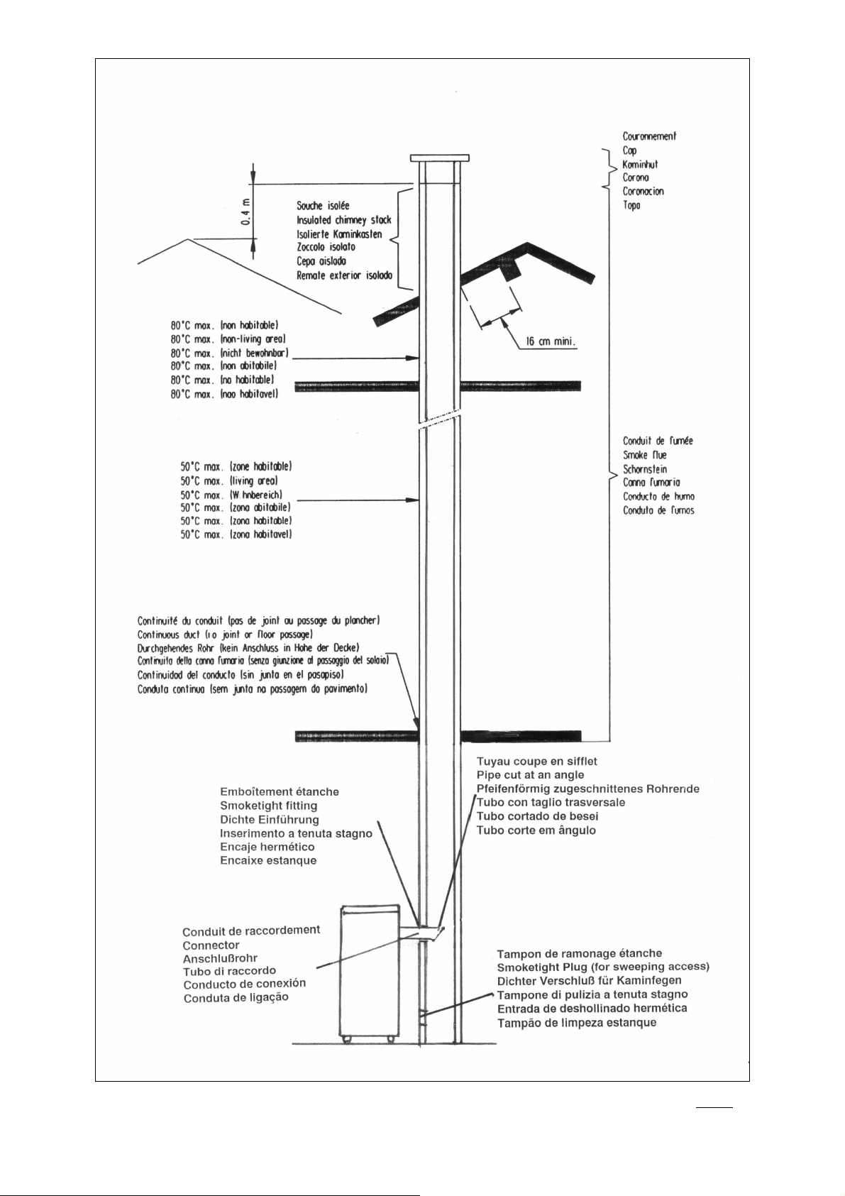
Fig. 1
26
Page 27

Fig. 2
27
Page 28

Les descriptions et caractéristiques figurant sur ce document sont données à titre d'information et non d'engagement.
En effet, soucieux de la qualité de nos produits, nous nous réservons le droit d'effectuer,
sans préavis, toute modification ou amélioration.
***
***
******
Société Anonyme au capital de 6.404.454 €
R.C SEDAN 787 020 080 B - Sirène 787 020 080 00018
SIEGE SOCIAL
76 rue Forest - 08013 CHARLEVILLE-MEZIERES CEDEX
www.deville.fr
-
contact@deville.fr
28
 Loading...