

Page 1
P00
50930
-00
01/06
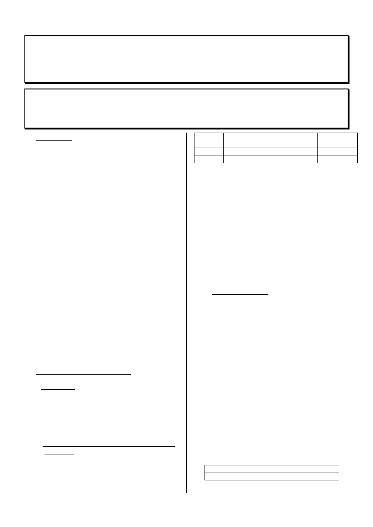
• CHEMINEES PRETES A POSER
CHEMINEES PRETES A POSER
CHEMINEES PRETES A POSERCHEMINEES PRETES A POSER
• READY TO INSTALL FIREPLACES
READY TO INSTALL FIREPLACES
READY TO INSTALL FIREPLACESREADY TO INSTALL FIREPLACES
• EINBAUFERTIGE KAMINE
EINBAUFERTIGE KAMINE
EINBAUFERTIGE KAMINEEINBAUFERTIGE KAMINE
• CHIMENEAS LISTAS PARA INSTALAR
CHIMENEAS LISTAS PARA INSTALAR
CHIMENEAS LISTAS PARA INSTALARCHIMENEAS LISTAS PARA INSTALAR
• CAMINETTI PRONTI PER LA POSA
CAMINETTI PRONTI PER LA POSA
CAMINETTI PRONTI PER LA POSACAMINETTI PRONTI PER LA POSA
C07335
C07335
C07335C07335
C07342
C07342
C07342C07342
• LAREIRAS PRONTAS A INSTALAR
LAREIRAS PRONTAS A INSTALAR
LAREIRAS PRONTAS A INSTALARLAREIRAS PRONTAS A INSTALAR
• VOORZETHAARDEN
VOORZETHAARDEN
VOORZETHAARDENVOORZETHAARDEN
NOTICE D'INSTALLATION ET D'EMPLOI
INSTALLATION AND OWNERS MANUAL
INSTALLATIONS- UND GEBRAUCHSANLEITUNG
INSTRUCCIONES PARA INSTALACIÓN Y EMPLEO
MANUALE DI INSTALLAZIONE E UTILIZZO
MANUAL DE INSTALAÇÃO E DE UTILIZAÇÃO
INSTALLATIE EN GEBRUIK
Page 2

FRANÇAIS
FRANÇAIS ................................
FRANÇAIS FRANÇAIS
................................................................
................................................................
.................................................
................................................................
ENGLISH
ENGLISH ................................
ENGLISHENGLISH
................................................................
................................................................
...................................................
................................................................
DEUTSCH
DEUTSCH ................................
DEUTSCH DEUTSCH
................................................................
................................................................
..................................................
................................................................
ESPA
ESPAÑÑÑÑOL
ESPAESPA
OL ................................
................................................................
OLOL
................................................................
..................................................
................................................................
ITALIANO
ITALIANO ................................
ITALIANO ITALIANO
................................................................
................................................................
..................................................
................................................................
PORTUGUÊS
PORTUGUÊS ................................
PORTUGUÊSPORTUGUÊS
................................................................
................................................................
.............................................
................................................................
NEDERLANDSE
NEDERLANDSE ................................
NEDERLANDSE NEDERLANDSE
................................................................
................................................................
................. p 3
..................................
................... p 13
......................................
.................. p 23
....................................
.................. p 33
....................................
.................. p 43
....................................
............. p 53
..........................
..........................................
................................................................
.......... p 6
....................
p 3
p 3 p 3
p 13
p 13 p 13
p 23
p 23 p 23
p 33
p 33 p 33
p 43
p 43 p 43
p 53
p 53 p 53
p 63333
p 6 p 6
2
Page 3

SOM
SOMM
SOMSOM
1
1 ---- PREAMBULE
PREAMBULE................................
1 1
PREAMBULE PREAMBULE
2
2 ---- CARACTERISTIQUES DE L'APP
CARACTERISTIQUES DE L'APPAREIL
2 2
CARACTERISTIQUES DE L'APP CARACTERISTIQUES DE L'APP
2.1 - Désignation
2.2 - Puissance calorifique nominale et autonomie en allure réduite
2.3 - Description
2.4 - Encombrement
2.5 - Environnement
3
3 ---- CARACTERISTIQUES DE L'INSTALLATION POUVANT RECEVOIR L'APPAREIL
CARACTERISTIQUES DE L'INSTALLATION POUVANT RECEVOIR L'APPAREIL................
3 3
CARACTERISTIQUES DE L'INSTALLATION POUVANT RECEVOIR L'APPAREILCARACTERISTIQUES DE L'INSTALLATION POUVANT RECEVOIR L'APPAREIL
3.1 - Dénomination des diverses parties du circuit d'évacuation des fumées
3.2 - Nature et caractéristiques dimensionnelles du conduit de fumée auquel doit être
obligatoirement raccordé l'appareil
3.2.1 - Nature du conduit de fumée
3.2.2 - Section minimale du conduit
3.2.3 - Quelques préconisations générales
3.3 - Nature et caractéristiques du conduit de raccordement entre l'appareil et le conduit de
fumée
3.4 - Conditions de tirage
3.5 - Ventilation du local où l'appareil est installé
3.6 - Raccordement électrique de la soufflerie
3.7 - Nature des murs et des parois avoisinant l’appareil
4
4 ---- INSTALLATION DE
INSTALLATION DE LA CHEMINEE PRETE A POSER
4 4
INSTALLATION DE INSTALLATION DE
5
5 ---- UTILISATION DE L'APPAREIL
UTILISATION DE L'APPAREIL ................................
5 5
UTILISATION DE L'APPAREIL UTILISATION DE L'APPAREIL
5.1 - Premier allumage
5.2 - Combustible
5.2.1 - Combustible recommandé
5.2.2 - Combustibles interdits
5.3 - Emploi des organes de manoeuvre et des accessoires
5.4 - Utilisation
5.4.1 - Allumage
5.4.2 - Fonctionnement
6
6 ---- CONSEILS DE RAMONAGE ET D'ENTRETIEN
CONSEILS DE RAMONAGE ET D'ENTRETIEN ................................
6 6
CONSEILS DE RAMONAGE ET D'ENTRETIEN CONSEILS DE RAMONAGE ET D'ENTRETIEN
6.1 - Ramonage et entretien du conduit de fumée
6.2 - Entretien courant de l'appareil
6.2.1 - Réglage de la fermeture de porte
7
7 –––– CONDITIONS GENERALES DE GARANTIE
CONDITIONS GENERALES DE GARANTIE ................................
7 7
CONDITIONS GENERALES DE GARANTIE CONDITIONS GENERALES DE GARANTIE
................................................................
................................................................
AREIL................................
AREILAREIL
LA CHEMINEE PRETE A POSER ................................
LA CHEMINEE PRETE A POSER LA CHEMINEE PRETE A POSER
................................................................
................................................................
MAIRE
AIRE
MM
AIREAIRE
................................................................
................................................................
..............................................................
................................................................
...................................................
................................................................
.......................................................
................................................................
....................................
................................................................
.............................. 4
............................................................
................ 5
................................
.........................................
................................................................
..........................................
................................................................
................... 10
......................................
.......................
..............................................
......... 7
..................
.......... 8
....................
.... 4
4
........
4 4
4
4 4
5
5 5
7
7 7
8
8 8
10
10 10
11112222
3
Page 4
ATTENTION :
POUR EVITER TOUT RISQUE D'INCENDIE, CET APPAREIL DOIT ETRE INSTALLE DANS LES
REGLES DE L'ART, CONFORMEMENT AUX REGLES TECHNIQUES RAPPELEES DANS CETTE NOTICE.
CET APPAREIL DOIT ETRE INSTALLE CONFORMEMENT AUX SPECIFICATIONS DES D.T.U. EN VIGUEUR.
L’INSTALLATION PAR UN PROFESSIONNEL QUALIFIE EST RECOMMANDEE.
Nous vous conseillons de lire attentivement, et au complet, le texte de la notice afin de tirer le meilleur
usage et la plus grande satisfaction de votre appareil DEVILLE.
Toutes les réglementations locales et nationales, ainsi que les normes européennes, doivent être
respectées lors de l’utilisation de l’appareil.
Le non respect des instructions de montage, d'installation et d'utilisation entraîne la responsabilité de celui
qui les effectue. L'appareil ne doit pas être modifié.
1 - PREAMBULE
• Les cheminées "prête à poser" s'installent
comme un poêle à bois. Les règles d'installation
sont les mêmes, notamment en ce qui concerne :
- La nature et les exigences de mise en oeuvre
du conduit de cheminée compatible avec cette
utilisation.
- Le raccordement de l'appareil au conduit de
cheminée.
- La ventilation du local.
• Le chapitre 4 traite de la partie spécifique à la
cheminée "prête à poser" :
- Pose contre un mur d'adossement.
- Ajustement en hauteur.
•
Attention, les cheminées "prête à poser" ne
permettent pas le raccordement de gaines de
sortie d'air chaud : la sécurité de l'environnement
n'est plus assurée si les écrans protégeant le mur
d'adossement sont modifiés (percés, déplacés
…).
• Nous rappelons ci-après les recommandations
élémentaires à respecter. Les DTU 24-2-2 et
24.1 décrivent de façon complète les dispositions
nécessaires concernant les circuits d'évacuation
des fumées et d'amenée d'air frais.
• Les cheminées prêtes à poser C07335 et
C07342 sont conformes à la norme française NF
EN 13240.
2 - CARACTERISTIQUES DE L'APPAREIL
2.1 - Désignation
Les cheminées "prête à poser" sont des appareils de
chauffage continu à combustion sur grille,
fonctionnant exclusivement au bois, à chambre de
combustion semi-fermée, et conçus pour être
adossés à un mur sans protection supplémentaire.
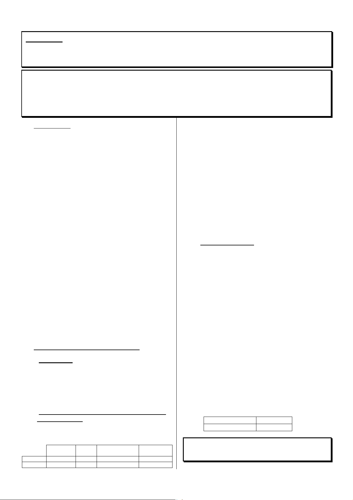
2.2 - Puissance calorifique nominale et autonomie
en allure réduite
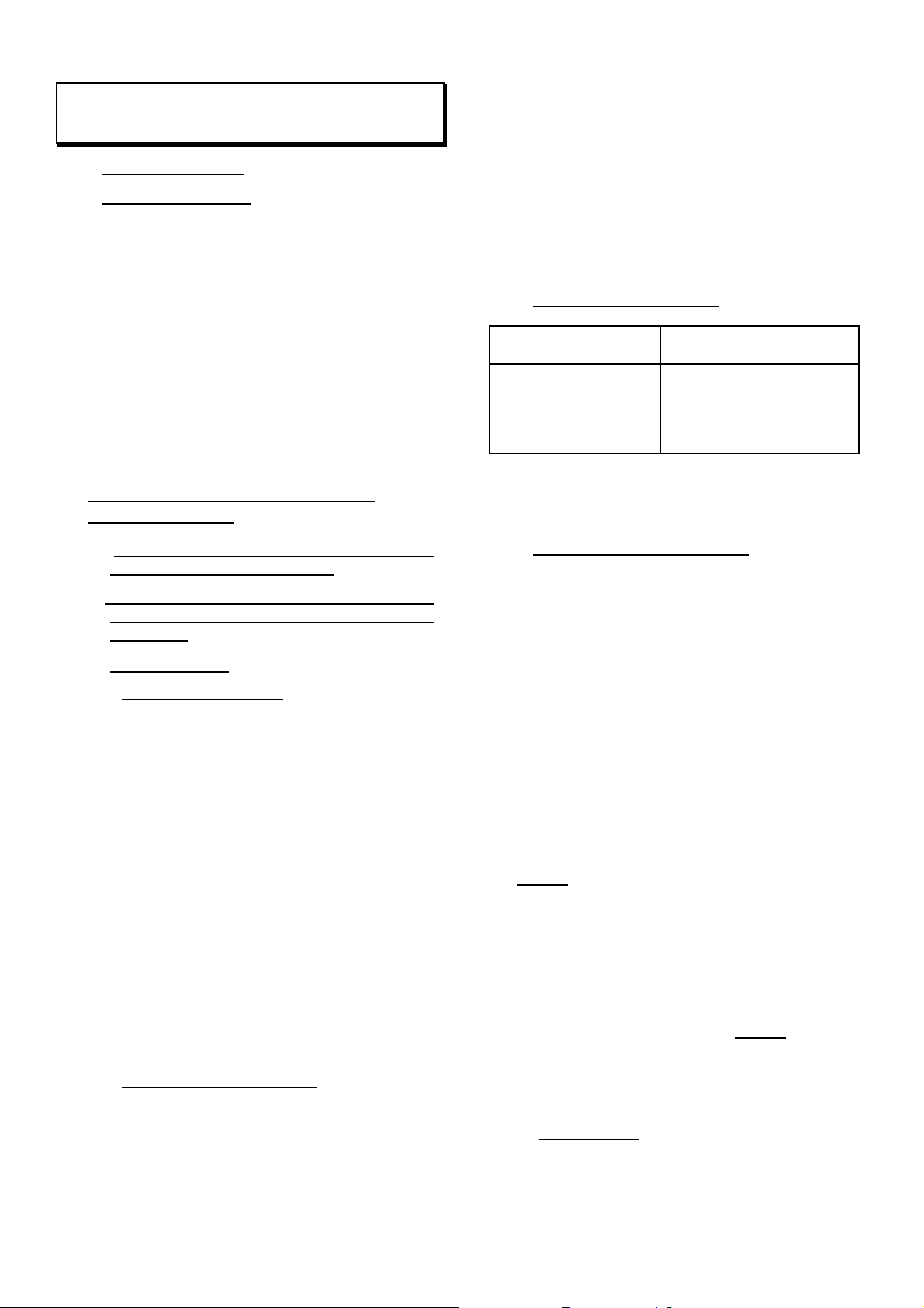
• Puissance calorifique nominale suivant norme NF
EN 13240 pendant l'essai d'allure normale :
Puissance
nominale
C07335 14 kW 12 Pa 10,5 g/s 321 °C
C07342 10 kW 12 Pa 10,5 g/s 299 °C
Tirage Débit massique
des fumées
Température
des fumées
- Obtenue sous un tirage de 12 Pa avec une
charge de bois de 10 kg pour C07342 et 14 kg
pour C07335, constituée de 3 bûches de bois
dur non fendues.
- La puissance annoncée est la puissance
moyenne obtenue au cours de cet essai de 3
heures.
- Pour obtenir ce régime de puissance,
recharger sur un lit de braises d'environ :
. 300 g, soit 3 cm d’épaisseur pour
C07342.
. 500 g, soit 4 cm d’épaisseur pour
C07335.
Le réglage d'air doit être ouvert en position maximale.
•
Une autonomie supérieure à 10 h, à puissance
réduite, est obtenue avec un chargement complet
en fermant complètement le réglage d'air.
2.3 - Description (Fig. 1)
• L'appareil est constitué d'un foyer et d'un
ensemble constituant l'échangeur et l'habillage. Il
est livré en 2 colis.
• Les principaux éléments constituant le foyer sont
indiqués et repérés sur la figure 1 :
- La chambre de combustion est en acier de 4
mm, le fond du foyer est doublé d'une plaque
d'âtre en fonte.
- Les portes sont en fonte, munies de joints qui
assurent l'étanchéité.
- La tirette de réglage située en partie basse de
la porte permet de choisir l'allure de feu.
- Une entrée d'air secondaire est intégrée en
partie haute du vitrage, pour le maintenir
propre et assurer une meilleure combustion
du bois.
- La cheminée prête à poser C07342 est
équipée d’une soufflerie, avec motoventilateur à deux vitesses, qui permet
d'accélérer la convection autour du foyer.
• Poids net de l'appareil :
C07335 140 kg
C07342 180 kg
Pour la manutention de l’appareil ôter la ou les
portes ainsi que les différentes pièces en fonte
qui se trouvent dans le foyer.
4
Page 5
2.4 - Encombrement (Fig. 2)
2.5 - Environnement (Fig. 2)
• L'appareil doit être installé contre un mur. Le
cache-tuyau réglable permet d'ajuster la hauteur
de l'appareil sur celle du plafond.
• Le jeu d'écrans fourni avec l'appareil assure la
protection contre le rayonnement et ménage des
circuits d'air de refroidissement des murs de la
maison. Ils doivent impérativement être installés
en respectant les indications ci-après.
• L'appareil doit être raccordé au conduit de
cheminée par l'intermédiaire d'un conduit de
raccordement de ∅ 180 mm pour C07335 et ∅
153 mm pour C07342 (voir paragraphe 3.3).
3 - CARACTERISTIQUES DE L'INSTALLATION
POUVANT RECEVOIR L'APPAREIL
3.1 - Dénomination des diverses parties du circuit
d'évacuation des fumées (Fig. 3)
3.2 - Nature et caractéristiques dimensionnelles
du conduit de fumée auquel doit être
obligatoirement raccordé l'appareil
3.2.1 - Nature du conduit de fumée
3.2.1.1 - Cas d'un conduit neuf
• Utilisation des matériaux suivants :
- Boisseaux de terre cuite conformes à la NF P
51-311.
- Boisseaux en béton conformes à la NF P 51-
321.
- Conduits métalliques composites conformes
aux NF D 35-304 et NF D 35-303 ou ayant
reçu un Avis Technique favorable pour cet
usage.
- Briques en terre cuite conformes à la NF P
51-301.
- Briques réfractaires conformes à la NF P 51-
302.
• L'utilisation de matériaux isolés d'origine permet
d'éviter la mise en place d'une isolation sur le
chantier, notamment au niveau des parois dans
la traversée des combles et sur la hauteur de la
souche (résistance thermique minimale : 0,43 m²
k/W).
3.2.1.2 - Cas d'un conduit existant
• L'installateur prend à son compte la
responsabilité des parties existantes. Il doit
vérifier l'état du conduit et y apporter les
aménagements nécessaires pour son bon
fonctionnement et la mise en conformité avec la
réglementation.
• Ramoner le conduit puis procéder à un examen
sérieux pour vérifier :
- La compatibilité du conduit avec son
utilisation.
- La stabilité.
- La vacuité et l'étanchéité (annexe II du DTU 24-
1).
• Si le conduit n'est pas compatible, réaliser un
tubage à l'aide d'un procédé titulaire d'un Avis
Technique favorable, ou mettre en place un
nouveau conduit.
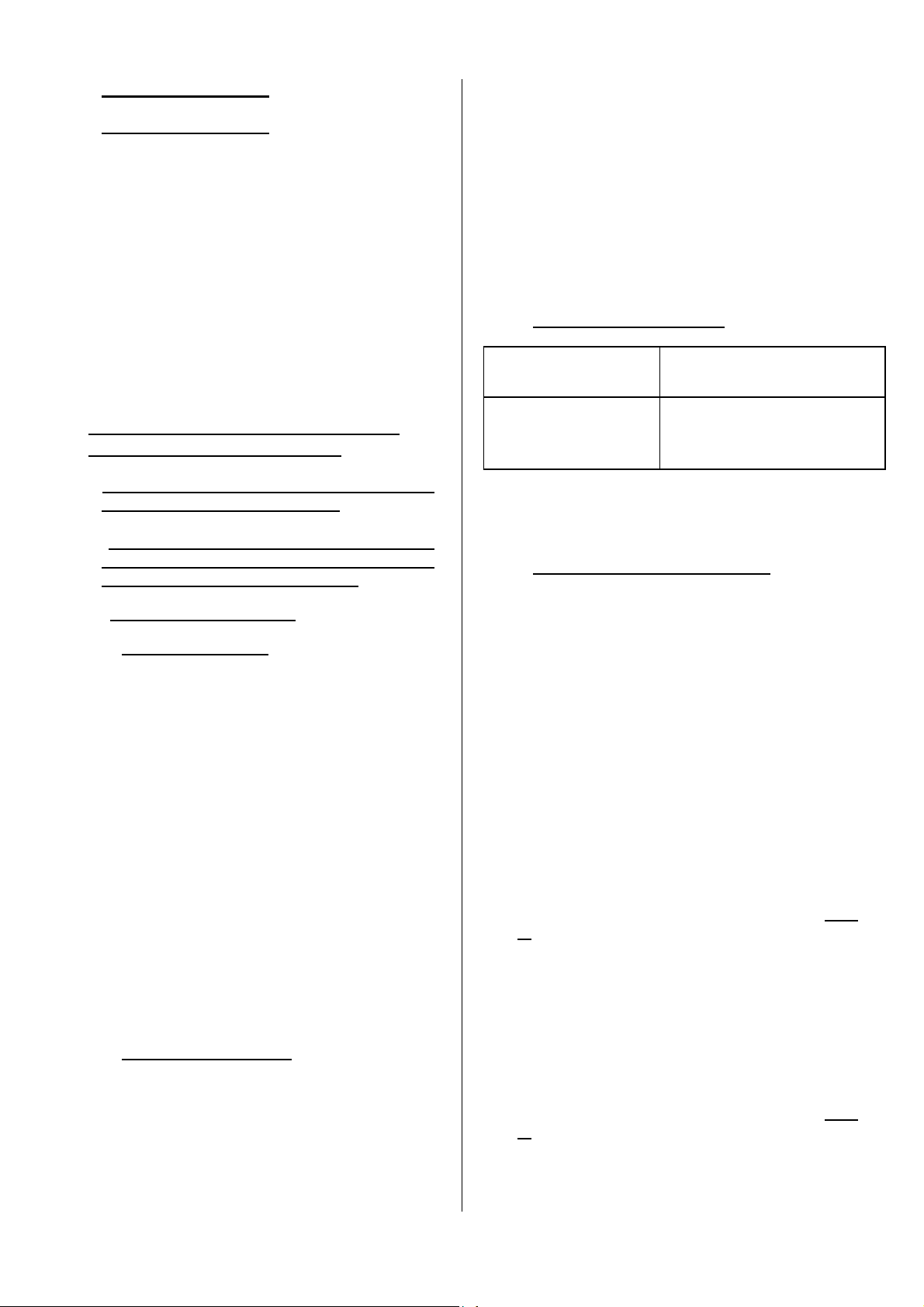
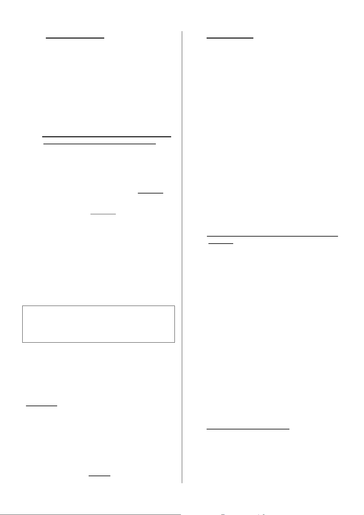
3.2.2 - Section minimale du conduit
Réglementation Fonctionnement portes fermées
Boisseaux carrés ou
rectangulaires
Conduits circulaires
Section minimale 2,5 dm²
Diamètre minimal 153 mm
Dans tous les cas, la section du conduit doit être au
moins égale à celle de la buse de raccordement sur
l’appareil.
3.2.3 - Quelques préconisations générales
• Un bon conduit doit être construit en matériaux
peu conducteurs de la chaleur pour qu'il puisse
rester chaud.
• L'habillage du conduit doit permettre de limiter la
température superficielle extérieure à :
- 50° C, dans les parties habitables.
- 80° C, dans les parties non habitables ou
inaccessibles.
• Le conduit doit être absolument étanche, sans
rugosité et stable.
• Le conduit ne doit pas comporter de variations de
section brusques (pente par rapport à la verticale
inférieure à 45°).
• Le conduit doit déboucher à 0,4 m au moins au-
dessus du faîte du toit et des toits voisins (Fig.
3).
• Deux appareils ne doivent pas être raccordés sur
un même conduit.
• Le conduit doit déboucher dans la pièce où sera
installé l'appareil, sur une hauteur de 50 mm au
moins.
• Sa face intérieure doit être éloignée de 16 cm au
moins de tout bois et matière combustible (Fig.
3).
• Le conduit ne doit pas comporter plus de deux
dévoiements, c'est-à-dire plus d'une partie non
verticale.
5
Page 6
- Si c'est un conduit maçonné :
L'angle des dévoiements ne doit pas excéder
45° pour une hauteur totale du conduit limitée à
5 m. Pour une hauteur supérieure, l'angle de
dévoiement est limité à 20°.
- Si c'est un conduit métallique isolé :
L'angle des dévoiements ne doit pas excéder
45° avec une limitation de hauteur de 5 m
entre le haut et le bas du dévoiement. La
hauteur totale du conduit n'est pas limitée.
• Les boisseaux doivent être montés partie mâle
vers le bas afin d'éviter le passage des coulures
à l'extérieur.
• L'étanchéité, l'isolation, les traversées de plafond
et plancher, les écarts au feu doivent être
réalisés dans le strict respect du DTU 24-2-2.
3.3 - Nature et caractéristiques du conduit de
raccordement entre l'appareil et le conduit
de fumée
• Un conduit de raccordement doit être installé
entre l'appareil et le débouché du conduit de
fumée. Ce conduit doit être réalisé à l'aide d'un
tubage polycombustible rigide ou flexible,
justifiable d'un Avis Technique favorable pour une
desserte directe de foyer fermé.
A noter que sont interdits l'aluminium, l'acier
aluminié et l'acier galvanisé.
A noter que sont autorisés : la tôle noire (ép. Mini
2 mm), la tôle émaillée (ép. Mini 0,6 mm), l’acier
inoxydable (ép. Mini 0,4 mm).
• Ce conduit doit être visible sur tout son parcours
et ramonable de façon mécanique. Sa dilatation
ne doit pas nuire à l'étanchéité des jonctions
amont et aval ainsi qu'à sa bonne tenue
mécanique et à celle du conduit de fumée. Sa
conception et, en particulier, le raccordement
avec le conduit de fumée doit empêcher
l'accumulation de suie, notamment au moment
du ramonage.
• Les jonctions avec l'appareil d'une part et le
conduit de fumée d'autre part doivent être
réalisées dans le strict respect du DTU 24-2-2 et
des spécifications du constructeur du tube, en
utilisant tous les composants préconisés
(embouts, raccords, etc...).
• La section du conduit de raccordement doit être
au moins égale à celle de la buse de
raccordement sur l'appareil.
• Dans le cas où le conduit de raccordement est
horizontal, une pente ascendante de 5 cm par
mètre doit exister.
ATTENTION :
La surface située dans l'intervalle de 200 mm
autour du conduit de raccordement doit être
réalisée en matériaux incombustibles (béton,
briques). Toutefois, la réalisation en matériaux
combustibles ou en matériaux incombustibles se
dégradant au-dessus de 90 °C est autorisée,
sous réserve d'exécuter une isolation thermique
des surfaces soumises au rayonnement direct
du conduit de raccordement. L'isolant employé
doit être classé M.O. (laine de roche, fibres
céramiques...) (Fig. 4).
3.4 - Conditions de tirage
• Le tirage est mesuré sur le conduit de
raccordement à environ 50 cm après la buse de
l'appareil.
• Tirage nécessaire au bon fonctionnement porte
fermée :
- 6 Pa en allure réduite (0,6 mm de C.E).
- 12 Pa en allure normale (1,2 mm de C.E).
• La mise en place d'un modérateur de tirage est
vivement recommandée. Il peut être installé :
- Sur le conduit de raccordement, dans le
cache-tuyau, au-dessus de l'écran du cachetuyau, dans le cas d'un départ par le dessus.
- Sur le conduit de cheminée, dans le cas d'un
départ par l'arrière.
• Le modérateur permet d’obtenir un bon
fonctionnement, même dans des conditions de
tirage importantes (conduits hauts, tubage). Le
modérateur doit être facilement visible et
accessible et installé dans la pièce où se trouve
l’appareil.
• Le volet modérateur de tirage n’a pas d’influence
sur le fonctionnement de l’appareil lorsque la
porte est ouverte.
3.5 - Ventilation du local où l'appareil est installé
• Le fonctionnement de l'appareil nécessite un
apport d'air supplémentaire à celui nécessaire au
renouvellement d'air réglementaire. Cette
amenée d'air est obligatoire lorsque l'habitation
est équipée d'une ventilation mécanique.
• La prise d'amenée d'air doit être située soit
directement à l'extérieur, soit dans un local
ventilé sur l'extérieur, et être protégée par une
grille.
• La sortie d'amenée d'air doit être située le plus
près possible de l'appareil. Elle doit être obturable
lorsqu’elle débouche directement dans la pièce.
Pendant le fonctionnement de l’appareil,
s’assurer qu’elle soit libre de toute obstruction.
6
Page 7
• La section d'entrée d'air doit être au minimum
égale au quart de la section du conduit de fumée
avec un minimum de 50 cm² pour une utilisation
uniquement porte fermée.
• Il peut être nécessaire de stopper l'extracteur de
la ventilation mécanique pour éviter le
refoulement des fumées dans la pièce lors de
l'ouverture de la porte.
3.6 - Raccordement électrique de la soufflerie
• Le raccordement sur l'installation fixe en 230 V +
terre doit être réalisé par l'intermédiaire du câble
souple.
• Il peut s'effectuer, au choix, par :
- Fiche de prise de courant devant rester
accessible.
- Raccordement sur borne fixe. Dans ce cas,
l'installation devra être équipée d'un dispositif
de séparation omnipolaire ayant une distance
d'ouverture des contacts supérieure à 3 mm.
• L'installation devra être conforme à la NFC
15100, en particulier le branchement de la terre
(fil vert et jaune) devra être effectué.
3.7 - Nature des murs et des parois avoisinant
l’appareil
Placer la cheminée prête à poser à la distance
minimale de 300 mm des murs latéraux de
l’habitation et de tous matériaux combustibles.
L’appareil doit être installé sur un sol en matériaux
non combustibles.
Pour protéger le sol contre le rayonnement de
chaleur et la chute éventuelle de combustible, poser
l’appareil sur un écran métallique réfléchissant (ou un
sol carrelé) couvrant toute la surface du sol situé
sous et devant l’appareil.
L’appareil doit être installé sur un sol avec une
capacité portante suffisante. Si une construction
existante ne satisfait pas à cette condition préalable,
des mesures adéquates (par exemple, l’installation
d’une plaque de répartition de charge) doivent être
prises pour permettre au sol de supporter l’appareil.
4 - INSTALLATION DE LA CHEMINEE "PRETE A
POSER" (Fig. 5 et 6a)
Visserie fournie (Fig. 6b)
2 possibilités :
Dans ces deux cas de figure, l'écran de
plafond se situe à 60 mm du plafond.
Pour faire sauter les prédécoupes dans les
différents écrans, il suffit de percer avec un
foret de ∅ 6 au niveau des pointures de ∅ 2
mm.
• RACCORDEMENT PAR LE DESSUS (FIG 5)
Faire sauter les prédécoupes circulaires dans
l'écran de plafond et l'écran de cache-tuyau (les
autres sont laissées en place) (Fig. 7).
Fixer l'ensemble écran de mur + écran de plafond
au mur en utilisant les 6 vis B, chevilles D et
rondelles C, livrées dans le sachet notice et en
respectant une distance de 60 mm entre le
plafond et l'écran de plafond (Fig. 9).
Mettre l'appareil en place contre le mur.
Enfiler l'écran de cache-tuyau sur le conduit de
raccordement.
Mettre en place le conduit de raccordement.
Fixer l'écran de cache-tuyau sur l'écran de hotte
en utilisant les vis à tôle A, livrées dans le sachet
notice (Fig. 10).
• RACCORDEMENT PAR L'ARRIERE (FIG 6a)
Faire sauter la prédécoupe circulaire dans l'écran
de hotte et la prédécoupe rectangulaire dans
l'écran de mur. Les autres sont laissées en place
(Fig. 8).
Mettre en place l'appareil équipé de son tuyau de
raccordement (Fig. 6a).
Glisser l'ensemble écran de mur + écran de
plafond (Fig. 9) en respectant une distance de 60
mm entre le plafond et l'écran de plafond. Repérer
l'endroit des fixations au mur.
Uniquement pour C07342 : repérer la position des
fixations de la prédécoupe rectangulaire (Fig. 11).
Ecarter légèrement l'appareil du mur. Enfiler
l'écran de tuyau sur la partie horizontale du
conduit de raccordement (Fig. 11). Remettre
l'appareil contre le mur. Fixer l'ensemble écran de
mur + écran de plafond.
Uniquement pour C07342 : l’ensemble écran de
mur doit être équipé de la prédécoupe
rectangulaire (4 vis à tôle A livrées dans le sachet
notice, cette opération est à exécuter lorsque la
hauteur entre le sol et le plafond est supérieure à
2,4 m).
Mettre en place l'appareil contre le mur.
Ajuster le conduit de raccordement au conduit de
cheminée.
Fixer l'écran de cache-tuyau sur l'écran de hotte
en utilisant les vis à tôle A, livrées dans le sachet
notice.
• ENSUITE, DANS TOUS LES CAS (FIG. 12)
- Relever la côte H entre le haut de la hotte et le
plafond.
- Enfiler le cache-tuyau supérieur dans le cache-
tuyau inférieur et les ajuster à la côte H.
7
Page 8

- Percer 4 trous de ∅ 3,2 dans le cache-tuyau
supérieur au travers des 4 trous situés en partie
haute du cache-tuyau inférieur.
- Assembler les 2 cache-tuyaux à l'aide de 4 vis à
tôle A, livrées dans le sachet notice.
- Ecarter l'ensemble formé par les 2 cache-tuyaux
et le mettre en place sur la hotte de l'appareil.
- Immobiliser cet ensemble sur la hotte à l'aide de
4 vis à tôle A, livrées dans le sachet notice.
Cas particulier où le conduit de cheminée pénètre
dans la pièce sur une certaine hauteur et dont les
dimensions permettent son intégration dans le cachetuyau supérieur (Fig. 13).
5 - UTILISATION DE L'APPAREIL
• Ce "foyer fermé" est un véritable appareil de
chauffage :
- Rendement élevé.
- Fonctionnement en allure réduite de longue
durée.
5.1 - Premier allumage
• Après le premier allumage (voir paragraphe
5.4.1), faire un feu modéré pendant les premières
heures en limitant le chargement de l'appareil
(une bûche de ø 15 cm) avec la tirette d'air en
allure intermédiaire (Fig. 14) : montée en
température progressive de l'ensemble des
éléments de la cheminée et dilatation normale de
l'appareil.
• Pendant les premières utilisations, une odeur de
peinture peut se dégager de l'appareil. Aérer la
pièce pour limiter ce désagrément.
• Ne pas raccorder la Prête à Poser sur un conduit
desservant plusieurs appareils.
5.2 - Combustible
5.2.1 - Combustible recommandé
• Bûche de bois dur d’une longueur maximum de :
- 57 cm pour C07342
- 63 cm pour C07335
(chêne, charme, hêtre, châtaignier, etc...)
Hauteur maximale de chargement :
- 20 cm pour C07342
- 25 cm pour C07335.
• Nous vous conseillons d'utiliser du bois très sec
(20 % d'humidité maximum), soit 2 ans de
stockage sous abri après la coupe, afin d'obtenir
de meilleurs rendements et d'éviter le bistrage du
conduit de fumée et de la vitre.
• Eviter l'utilisation des bois résineux (pins, sapins,
épicéas...) qui nécessitent un entretien plus
fréquent de l'appareil et du conduit.
5.2.2 - Combustibles interdits
• Tous les combustibles autres que le bois sont
interdits, notamment le charbon et ses dérivés.
• Les flambées de petits bois, sarments,
planchettes, paille, carton, combustibles liquides
sont dangereuses et à exclure.
• L’appareil ne doit pas être utilisé comme un
incinérateur à déchets.
5.3 - Emploi des organes de manoeuvre et des
accessoires
• Tirette de réglage d'air (Fig. 14) : elle doit être
manoeuvrée par l'intermédiaire du tisonnier.
• Poignée de porte : elle doit être manoeuvrée par
l'intermédiaire du tisonnier (Fig. 15).
• Raclette (Fig. 16) : pour le décendrage et le
nettoyage de l’appareil
Ne vous brûlez pas les mains inutilement servezvous des accessoires.
5.4 – Utilisation
5.4.1 - Allumage
• Ouvrir la tirette de réglage d'air en position allure
normale (Fig. 14).
• Placer sur la grille du papier froissé et du petit
bois très sec (brindilles), puis des branches de
bois fendues de section plus importante (ø 3 à 5
cm environ).
• Enflammer le papier et refermer la porte (ou la
laisser légèrement entrouverte pour accélérer
l'embrasement).
• Lorsque la charge de petit bois est bien
enflammée, ouvrir la porte, charger l'appareil
avec le combustible recommandé et agir sur les
organes de manœuvres pour obtenir l’allumage
désiré.
5.4.2 - Fonctionnement
5.4.2.1 – Fonctionnement intermittent et continu
• Le fonctionnement intermittent nécessite un
rechargement tous les ¾ d’heures.
Il faut privilégier ce mode de fonctionnement
particulièrement respectueux de l’environnement.
• L’appareil peut également assurer un
fonctionnement continu quand les contraintes de
l’intermittence ne peuvent être respectées ou
qu’une puissance réduite est recherchée. Dans
ce cas, la pleine puissance peut être obtenue sur
une durée de 3 heures et une allure lente, à faible
puissance, d’une durée de 10 heures est possible
avec une charge de 10 kg pour C07342, 13 kg
pour C07335.
8
Page 9
La puissance calorifique nominale en fonctionnement
intermittent :
• Obtenue sous un tirage de 12 Pa, avec une
charge de bois de :
o 3,3 kg pour C07335
o 2,4 kg pour C07342
sous forme d’une bûche de bois dur non
fendue.
• Recharger tous les ¾ d’heure sur un lit de
braises de :
o 0,5 kg pour C07335
o 0,4 kg pour C07342
(soit 3 cm d’épaisseur) avec la tirette d’air au
maximum.
• La puissance annoncée est la puissance
moyenne obtenue avec chaque charge de ¾
d’heure.
La puissance calorifique nominale en fonctionnement
continu :
• Obtenue sous un tirage de 12 Pa, avec une
charge de bois de :
o 13 kg pour C07335
o 10 kg pour C07342
constituée de 2 bûches de bois dur non
fendues.
• Recharger toutes les 3 heures sur un lit de
braises d’environ :
o 0,5 kg pour C07335
o 0,35 kg pour C07342
(soit 3 cm d’épaisseur) avec la tirette d’air au
maximum.
• La puissance annoncée est la puissance
moyenne obtenue avec chaque charge de 3
heures.
La combustion lente, autonomie supérieure à 10 h en
fonctionnement continu :
• Obtenue sous un tirage de 6 Pa avec une
charge de bois de :
o 13 kg pour C07335
o 10 kg pour C07342
constituée d’une bûche de bois dur non
fendue en privilégiant les grands diamètres
(supérieur à 16 cm).
• Recharger sur un lit de braises d’environ :
o 0,5 kg pour C07335
o 0,3 kg pour C07342
(soit 3 cm d’épaisseur) avec la tirette d’air
fermée.
5.4.2.2 – Conduite du feu
• L'allure désirée est obtenue en agissant sur la
tirette de réglage d’air (voir § 5.3) et en
choisissant une charge correspondant aux
besoins :
- Pour un chauffage maximum, charger
l'appareil avec 3 bûches d'environ 10 cm de
diamètre (tirette d’air en position allure
normale) (Fig. 14)
.
Utiliser cette allure uniquement de façon
temporaire, pour mettre en température les
locaux après une absence prolongée.
- Pour une allure intermédiaire, utiliser une
charge moins importante : une ou deux
bûches (tirette d’air en position intermédiaire)
(Fig. 14)
.
- Pour un chauffage de longue durée en allure
lente, utiliser une ou deux bûches non
fendues de diamètre supérieur à 15 cm (tirette
d’air en position fermée) (Fig. 14).
• Pour obtenir une allure lente de longue durée,
procéder au chargement sur un lit de braises à
peine rougeoyantes.
• Pour obtenir un embrasement rapide, relancer le
feu avec du petit bois, effectuer le chargement,
maintenir éventuellement la porte entrouverte
pendant quelques minutes pour accélérer
l'embrasement, en gardant l'appareil sous
surveillance, puis refermer la porte et agir sur les
organes de manœuvres (§ 5.4). Cette opération
permet d'accélérer la reprise, notamment si le
bois est humide.
• Effectuer les changements d'allure (passage de
l’allure normale à l’allure réduite par exemple)
avant les rechargements, pendant la phase de
combustion des braises, pour permettre à
l'appareil et au conduit des fumées de changer
progressivement de régime.
• Pour éviter les refoulements des fumées et les
chutes de cendres dans la pièce au moment des
rechargements, l’ouverture de la porte nécessite
plusieurs précautions :
- Entrouvrir la porte, marquer un temps d’arrêt
pour amorcer le tirage, puis ouvrir lentement
la porte.
• Le fonctionnement continu en allure lente, surtout
pendant les périodes de redoux (tirage
défavorable) et avec du bois humide, entraîne
une combustion incomplète qui favorise les
dépôts de bistre et de goudron :
- Alterner les périodes de ralenti par des retours
en fonctionnement à l'allure normale.
- Privilégier une utilisation avec de petites
charges.
• Après un fonctionnement en allure lente, la vitre
peut s'obscurcir à cause d'un léger bistrage, ce
dépôt disparaît normalement à plus vive allure
par pyrolyse.
La mise en place d’un volet modérateur de tirage,
sur le conduit de raccordement, permettra de
maîtriser le choix de l’allure notamment de la
puissance réduite permettant d’obtenir le ralenti
de longue durée.
9
Page 10
5.4.2.3 – Soufflerie (uniquement pour C07342)
- DESCRIPTION
(Fig. 24)
L'ensemble soufflerie comprend :
- un caisson
- un support ventilateur avec motoventilateur 230 V 50 Hz.
- un cache ventilateur
- un sélecteur à 2 vitesses et arrêt
Pour les versions avec thermostats :
- un thermostat qui déclenche la mise en
service du ventilateur en fonction de la
température du foyer, si le sélecteur se
trouve en position I ou II.
- un sélecteur AUTO/MANU
- UTILISATION
Choisir une vitesse de ventilation :
. Petite vitesse, sélecteur en position I
. Grande vitesse, sélecteur en position II
Mettre l'appareil en chauffe (voir notice Foyer/Insert).
Pour les versions avec thermostats, choisir le
fonctionnement automatique (AUTO) ou manuel
(MANU) avec le sélecteur :
. En position MANU : marche et arrêt forcés du
ventilateur. Cette position permet un démarrage
immédiat de la soufflerie et nécessite un arrêt
manuel.
. En position AUTO : marche automatique du
ventilateur quand l'ensemble de l'appareil est
chaud, généralement dans l'heure qui suit
l'allumage. Son fonctionnement est interrompu
quand l'appareil est froid, généralement à
l'extinction du foyer.
Pour bénéficier à la fois d'un démarrage immédiat et
de l'arrêt automatique, utiliser la position MANU à
l'allumage, puis passer en position AUTO une fois
que l'appareil est chaud. Il s'arrêtera alors
automatiquement.
5.4.2.4 - Décendrage
• L'air utilisé pour la combustion du bois arrive
sous la grille lorsque la tirette de réglage d'air est
ouverte. Cet air assure également le
refroidissement de la grille. Il est donc
indispensable, pour obtenir les performances
optimales et éviter la dégradation de la grille sous
l'effet de la surchauffe, d'éviter son obstruction en
procédant régulièrement au décendrage et à
l'évacuation des cendres.
• Utiliser la raclette pour effectuer le décendrage
de la grille (Fig. 16).
Extraction du cendrier :
- Ouvrir la porte, puis extraire le cendrier.
• Enlever périodiquement les cendres
accidentellement répandues dans le
compartiment cendrier.
• Le cendrier, situé sous la grille, est facilement
extrait en le tirant à l'aide du tisonnier.
Le niveau des cendres ne doit jamais
atteindre la grille en fonte du foyer :
décendrage tous les 2 à 3 jours au moins.
5.4.2.5 - Règles de sécurité
• Ne jamais jeter d'eau pour éteindre le feu.
• La vitre et certaines parties de l'appareil sont très
chaudes : attention aux risques de brûlures
notamment pour les enfants.
• Le foyer dégage par rayonnement à travers le
vitrage, une importante chaleur : ne pas placer de
matériaux, ni d'objets sensibles à la chaleur à
une distance inférieure à 1,50 m de la zone
vitrée.
• Vider le contenu du cendrier dans un récipient
métallique ou ininflammable exclusivement
réservé à cet usage. Les cendres en apparence
refroidies peuvent être très chaudes même après
quelques temps de refroidissement.
• Ne pas mettre en place des matériaux facilement
inflammables au voisinage de l'appareil et dans le
bûcher.
• En particulier, ne pas stocker de bois sous
l’appareil (Fig. 17).
• En cas de feu de cheminée, mettre la tirette d’air
en position fermée.
6 - CONSEILS DE RAMONAGE ET D'ENTRETIEN
6.1 - Ramonage et entretien du conduit de fumée
• Le ramonage mécanique du conduit de fumée
est obligatoire. Il doit être réalisé plusieurs fois
par an dont une fois au moins pendant la saison
de chauffe. Un certificat doit être remis par un
professionnel.
• A l'occasion des ramonages, il faudra :
- Démonter le déflecteur (Fig. 18, 19, 20) :
. déposer le déflecteur (soulever le
déflecteur 1, l’avancer 2, descendre
l’arrière 3, le descendre 4 et le sortir
5 par le côté droit).
- Déposer la plaque arrière de foyer, et le tuyau
de raccordement.
10
Page 11
- Pour remonter le déflecteur, agir dans l'ordre
inverse du démontage.
- Vérifier complètement l'état de l'appareil et en
particulier les éléments assurant l'étanchéité :
joints et organes de verrouillage, pièces
d'appui (porte, châssis).
- Après avoir déposé le cache-tuyau :
. Vérifier l'état du conduit de fumée et du
conduit de raccordement : tous les
raccords doivent présenter une bonne
tenue mécanique et avoir conservé leur
étanchéité.
. Nettoyer à l'aspirateur le circuit de
convection autour du foyer, l'intérieur de la
hotte et les bouches de sortie d'air chaud.
- Nettoyer l’appareil à la brosse et à l’aspirateur.
En cas d'anomalie, faire réparer l'appareil
ou l'installation par un professionnel.
A la suite d’une longue période d’arrêt :
- Vérifier l’absence d’obstruction des conduits
avant un rallumage.
6.2 - Entretien courant de l'appareil
• Nettoyer le verre avec un chiffon humide et de la
cendre. Si c'est nécessaire, utiliser un produit de
nettoyage ménager adapté en respectant les
instructions des notices d'utilisation. Attendre que
l'appareil soit complètement refroidi pour
procéder à cette opération.
• Nettoyer régulièrement l’entrée d'air secondaire
(Fig. 21) :
- Gratter avec l'extrémité d'un objet métallique
(2), l’arête intérieure en haut de la porte fonte
pour enlever le bistre qui a pu s’y agglomérer.
- Enlever à l'aspirateur (1) les particules et
poussières qui sont coincées entre l’arête
intérieure en haut de la porte et le verre
(Fig. 22).
NOTA : Ces particules gênent la formation du film
d'air secondaire qui protège le vitrage du
contact direct avec les fumées et complète
la combustion du bois.
Ces opérations doivent être effectuées dès que le
verre est sale et impérativement après extinction
totale du foyer.
• Contrôler l'efficacité de la clenche de fermeture
de la porte et, si c'est nécessaire, effectuer les
réglages (voir paragraphe 6.2.1).
• Nettoyer régulièrement les bouches de sorties
d'air chaud du cache-tuyau. Elles se colmatent
d'autant plus rapidement que l'utilisation de
l'appareil est intensive. Choisir une fréquence
adaptée.
• Au cas où, pour quelque raison que ce soit, il
faudrait intervenir sur la soufflerie :
- Pour le C07342 (Fig. 26)
. Démontage du support ventilateur :
Dévisser de quelques tours les 3 vis
et enlever l’appui joint .
Enlever les 2 vis de fixation de la
soufflerie.
Sortir la soufflerie en tirant sur la grille.
. Remontage de la soufflerie :
Agir dans l’ordre inverse du
démontage.
. Plan électrique (Fig. 27)
6.2.1 - Réglage de la fermeture de porte
• Durcir la fermeture de porte : (Fig. 23)
- Procéder successivement par desserrage de
la vis (1) et serrage de la vis (2).
- Agir par 1/4 de tour sur les 2 vis et
recommencer l'opération si cela est
nécessaire.
NOTA : Cette opération augmente la pression du joint
d'étanchéité de la porte sur le foyer.
• Assouplir la fermeture de porte : (Fig. 23)
- Procéder successivement par desserrage de
la vis (2) et serrage de la vis (1).
- Agir par 1/4 de tour sur les 2 vis et
recommencer l'opération si cela est
nécessaire.
NOTA : Cette opération diminue la pression du joint
d'étanchéité de la porte sur le foyer.
11
Page 12

7 – CONDITIONS GENERALES DE GARANTIE
1. MODALITES
En dehors de la garantie légale, à raison des vices cachés, DEVILLE garantit le matériel en cas de vices
apparents ou de non-conformité du matériel livré au matériel commandé.
Sans préjudice des dispositions à prendre vis-à-vis du transporteur, les réclamations lors de la réception du
matériel sur les vices apparents ou la non-conformité, doivent être formulées auprès de DEVILLE par l’acheteur
dans les cinq jours de la constatation du vice par voie de lettre recommandée avec demande d’avis de
réception. Il appartient à l’acheteur de fournir toute justification quant à la réalité des vices ou des anomalies
constatées. L’acheteur doit, par ailleurs, laisser à DEVILLE toute facilité pour procéder à la constatation de ces
vices ou anomalies et pour y porter remède. De même l’acheteur doit tenir les matériels non conformes à la
disposition de DEVILLE, selon les instructions de cette dernière. Tout retour du matériel doit faire l’objet d’un
accord préalable.
2. ETENDUE
La garantie de DEVILLE couvre, à l’exclusion de toute indemnité ou dommages-intérêts, le remplacement
gratuit ou la réparation du matériel ou de l’élément reconnu défectueux (hors pièces d’usure) par ses services à
l’exclusion des frais de main-d’œuvre, de déplacement et de transport.
Sur les appareils émaillés, les craquelures ne sont jamais considérées comme un défaut de fabrication. Elles
sont la conséquence de différence de dilatation tôle-émail ou fonte-émail et ne modifient pas l’adhérence. Les
pièces de rechange fournies à titre onéreux sont garanties six mois à partir de la date de facture ; toute garantie
complémentaire consentie par un revendeur de DEVILLE n’engage pas DEVILLE. La présentation du certificat
de garantie portant le cachet à date du revendeur DEVILLE est rigoureusement exigée lorsque la garantie est
invoquée. Ce certificat doit être présenté lors de la demande de réparation de l’appareil sous garantie, ou bien
un talon ou un volet détachable de ce certificat doit, selon l’organisation propre à DEVILLE, être retourné à
celle-ci dans les délais impartis. A défaut, la date figurant sur la facture émise par DEVILLE ne peut être prise
en considération. Les interventions au titre de la garantie ne peuvent avoir pour effet de prolonger celle-ci.
3. DUREE
La durée de la garantie contractuelle assurée par DEVILLE est d’une année à compter de la date d’achat de
l’appareil par l’usager, sous réserve que les réclamations prévues au titre des modalités ci-dessus aient été
formulées dans les délais impartis. La réparation, le remplacement ou la modification de pièces pendant la
période de garantie ne peut avoir pour effet de prolonger la durée de celle-ci, ni de donner lieu en aucun cas à
indemnité pour frais divers, retard de livraison, accidents ou préjudices quelconques.
4. EXCLUSION
La garantie ne s’applique pas dans les cas suivants, sans que cette liste soit exhaustive :
Installation et montage des appareils dont la charge n’incombe pas à DEVILLE. En conséquence, DEVILLE ne
peut être tenue pour responsable des dégâts matériels ou des accidents de personne consécutifs à une
installation non conforme aux dispositions légales et réglementaires (par exemple l’absence de raccordement à
une prise de terre ; mauvais tirage d’une installation) ;
Usure normale du matériel ou utilisation ou usage anormal du matériel, notamment en cas d’utilisation
industrielle ou commerciale ou emploi du matériel dans des conditions différentes de celles pour lesquelles il a
été construit. C’est le cas par exemple du non-respect des conditions prescrites dans la notice DEVILLE :
exposition à des conditions extérieures affectant l’appareil telles qu’une humidité excessive ou variation
anormale de la tension électrique ;
Anomalie, détérioration ou accident provenant de choc, chute, négligence, défaut de surveillance ou d’entretien
de l’acheteur ;
Modification, transformation ou intervention effectuée par un personnel ou une entreprise non agréée par
DEVILLE ou réalisée avec des pièces de rechange non d’origine ou non agréées par le constructeur.
5. CONDITIONS PARTICULIERES DE GARANTIE
Ces conditions complètent et précisent les conditions générales de garanties ci-dessus et ont primauté sur
celles-ci, se reporter au feuillet ci joint « Conditions particulières de vente DEVILLE – Garantie ».
12
Page 13

TABLE OF CONTENTS
TABLE OF CONTENTS
TABLE OF CONTENTSTABLE OF CONTENTS
1
1 ---- FOREWORD
FOREWORD ................................
1 1
FOREWORD FOREWORD
2
2 ---- FIREPLACE CHARACTERISTICS
FIREPLACE CHARACTERISTICS ................................
2 2
FIREPLACE CHARACTERISTICS FIREPLACE CHARACTERISTICS
2.1 - Description
2.2 - Nominal heat output and reduced burn rate autonomy
2.3 - Description
2.4 - Dimensions
2.5 - Environment
3
3 ---- FIREPLACE INSTALLATION LOCATION CHARACTERISTICS
FIREPLACE INSTALLATION LOCATION CHARACTERISTICS............................
3 3
FIREPLACE INSTALLATION LOCATION CHARACTERISTICS FIREPLACE INSTALLATION LOCATION CHARACTERISTICS
3.1 - Designation of the various parts of the smoke removal system
3.2 - Type and dimensional characteristics of the chimney flue to which the fireplace must
beconnected.
3.2.1 - Chimney flue type
3.2.2 - Minimum flue cross-section
3.2.3 - A few general recommendations
3.3 - Type and characteristics of the connecting tube between the fireplace and the flue
3.4 - Draft conditions
3.5 - Ventilation of the room where the fireplace is installed
3.6 - Blower electrical connection
3.7 - Walls in the vicinity of the appliance
4
4 ---- INSTALLATION OF THE "READY TO INSTALL" FIREPLACE
INSTALLATION OF THE "READY TO INSTALL" FIREPLACE ..............................
4 4
INSTALLATION OF THE "READY TO INSTALL" FIREPLACE INSTALLATION OF THE "READY TO INSTALL" FIREPLACE
5
5 ---- FIREPLACE OPERATION
FIREPLACE OPERATION................................
5 5
FIREPLACE OPERATION FIREPLACE OPERATION
5.1 - Commissioning
5.2 - Combustible
5.2.1 - Recommended combustible
5.2.2 - Forbidden combustibles
5.3 - Operation of control devices and accessories
5.4 - Operation
5.4.1 - Lighting a fire
5.4.2 - Operation
6
6 ---- MAINTENANC
MAINTENANCE AND SWEEPING INSTRUCTIONS
6 6
MAINTENANC MAINTENANC
6.1 - Maintenance and sweeping of the chimney flue
6.2 - Routine maintenance
6.2.1 - Adjusting the door closing mechanism
7
7 –––– GLOBAL TERMS OF WARRANT
GLOBAL TERMS OF WARRANTYYYY ................................
7 7
GLOBAL TERMS OF WARRANT GLOBAL TERMS OF WARRANT
................................................................
................................................................
................................................................
................................................................
E AND SWEEPING INSTRUCTIONS ................................
E AND SWEEPING INSTRUCTIONSE AND SWEEPING INSTRUCTIONS
................................................................
................................................................
................................................................
................................................................
..................................................
................................................................
................................................................
................................................................
.....................................
................................................................
......................................
................................................................
............................ 15
........................................................
.............................. 1
............................................................
............................................
................................................................
.....................................
................................................................
.................. 17
....................................
............ 20
........................
..... 14
14
..........
14 14
...... 14
14
............
14 14
15
15 15
17777
1 1
17
17 17
20
20 20
..... 22
22
..........
22 22
13
Page 14
CAUTION
CAUTION :
CAUTIONCAUTION
:
TO PREVENT THE RISK OF FIRE, THIS FIREPLACE MUST BE INSTALLED IN ACCORDANCE
: :
WITH ACCEPTED TRADE PRACTICES AND IN COMPLIANCE WITH THE TECHNICAL REGULATIONS
STIPULATED IN THIS MANUAL.
THE INSTALLATION OF THIS APPLIANCE MUST COMPLY WITH CURRENT D.T.U. (French Code of Practice)
SPECIFICATIONS.
INSTALLATION BY A QUALIFIED TRADESMAN IS RECOMMENDED.
We strongly recommend that you take the time to thoroughly read and familiarize yourself with this manual
in order to obtain maximum enjoyment and satisfaction from your DEVILLE fireplace.
All local, national, and european regulations must be respected when using this appliance.
The nonobservance of the assembly, installation and operating instructions shall engage the liability of the
individual(s) concerned. The unit must not be modified.
1 - FOREWORD
• The "ready to install" fireplaces, models are to be
installed in the same manner as a wood burning
stove. The rules for installation are identical,
particularly as regards the following points :
- The type and installation requirements of the
chimney flue compatible with this usage.
- The connection of the fireplace to the chimney
flue.
- Room ventilation.
• Chapter 4 specifically concerns the "ready to
install" fireplace :
- Installation against a backing wall.
- Height adjustment.
•
Important, the "Ready-to-Install" fireplaces do not
allow the connection of hot air outlet ducts: the
safety of the environment can no longer be
ensured if the screens which protect the backing
wall are modified (pierced, moved).
• The following chapters provide basic
recommendations for proper fireplace operation.
The building technical rules DTU 24-2-2 and 24.1
fully describe the specifications related to smoke
evacuation and fresh air intake requirements.
• The ready-to-install fireplaces C07335 and
C07342 comply with the French standards NF EN
13240.
2 - FIREPLACE CHARACTERISTICS
2.1 - Description
The "ready to install" fireplaces, models are
exclusively wood-burning, grate-type continuous
combustion, semi-open heating appliances, and are
designed to be installed against a backing wall
without any additional protection.
2.2 - Nominal heat output and reduced burn rate
autonomy
• Nominal heat output in accordance with French
standard NF EN 13240 during the normal burn
rate test :
Power
rating
C07335 14 kW 12 Pa 10,5 g/s 321°C
C07342 10 kW 12 Pa 10,5 g/s 299°C
- Obtained with a draft of 12 Pa, and a wood
load of 10 kg for C07342, and 14 kg for model
C07335. Loads are comprised of 3 unsplit
hardwood logs.
- The output indicated is the average output
obtained during this 3-hour test.
- In order to obtain this output level, place on a
bed of approximately :
. 300 g of live coals, that is 3 cm thick for
C07342.
. 500 g, of live coals, that is 4 cm thick for
C07335.
The air intake must be fully open.
• An autonomy greater than 10 hours, at reduced
output, is obtained with a full load and by
completely closing the air inlet control.
2.3 - Description (Fig. 1)
• The fireplace consists of an insert, an exchanger
assembly and the trim. It is delivered in 2
packages.
• The main elements which make up the insert are
identified in figure 1 :
- The combustion chamber is made of 4 mm
thick steel and the back of the insert is
doubled with a cast iron hearth plate.
- The door is of cast iron and fitted with seals
ensuring air-tightness.
- The adjusting slide located on the lower
section of the door is used to set the burning
rate.
- A secondary air inlet is built into the upper part
of the glass door to keep it clean and to
provide better combustion on the wood.
- The ready-to-install fireplace C07342 is fitted
with a 2 speed electric fan, which speeds up
the convection around the hearth.
• Net weight of the appliance :
Draft Mass discharge
of smoke
C07335 140 kg
C07342 180 kg
Temperature
of smoke
14
Page 15
For handling of the appliance, remove the door or
doors and the various cast iron parts located in
the fireplace.
2.4 - Dimensions (Fig. 2)
2.5 - Environment (Fig. 2)
• The fireplace must be installed against a wall.
The adjustable tube cover enables the height of
the fireplace to be adjusted to that of the ceiling.
• The shields supplied with the fireplace provide
heat radiation protection and hide the air cooling
systems designed to protect the walls. It is
imperative that all shields be installed in strict
compliance with the indications below.
• The fireplace must be connected to the chimney
flue by means of a ∅ 180 mm connecting tube for
models C07335 and ∅ 153 mm connecting tube
for models C07342 (see paragraph 3.3).
3 - FIREPLACE INSTALLATION LOCATION
CHARACTERISTICS
3.1 - Designation of the various parts of the
smoke exhaust system (Fig. 3)
3.2 - Type and dimensional characteristics of the
chimney flue to which the fireplace must be
connected
3.2.1 - Chimney flue type
3.2.1.1 - In the case of a new flue
• The following materials may be used :
- Terracotta chimney blocks in compliance with
NF standard P 51-311.
- Concrete chimney blocks in compliance with
NF standard P 51-321.
- Composite metal chimney flues in compliance
with NF standards D 35-304 and D 35-303 or
which have been awarded a favorable
"Technical Report" for this purpose.
- Terracotta bricks in compliance with NF
standard P 51-301.
- Fire bricks in compliance with NF standard P
51-302.
• The use of pre-insulated materials avoid having
to install insulation at the job site, particularly for
walls at the attic level and over the height of the
stack (minimum thermal resistance:
0.43 m² k/W).
3.2.1.2 - In the case of an existing flue
• The installer shall bear the responsibility for
all existing sections. The condition of the flue
must be checked and the necessary
modifications made to ensure proper operation
and compliance with regulations.
• Sweep the flue, then perform a thorough
examination in order to verify the following
points :
- Compatibility of the flue with its usage.
- Stability.
- Vacuousness and tightness (Appendix II of DTU
24-1).
• If the flue is incompatible, insert chimney stack
tubing in accordance with a certified procedure,
or install a new chimney flue.
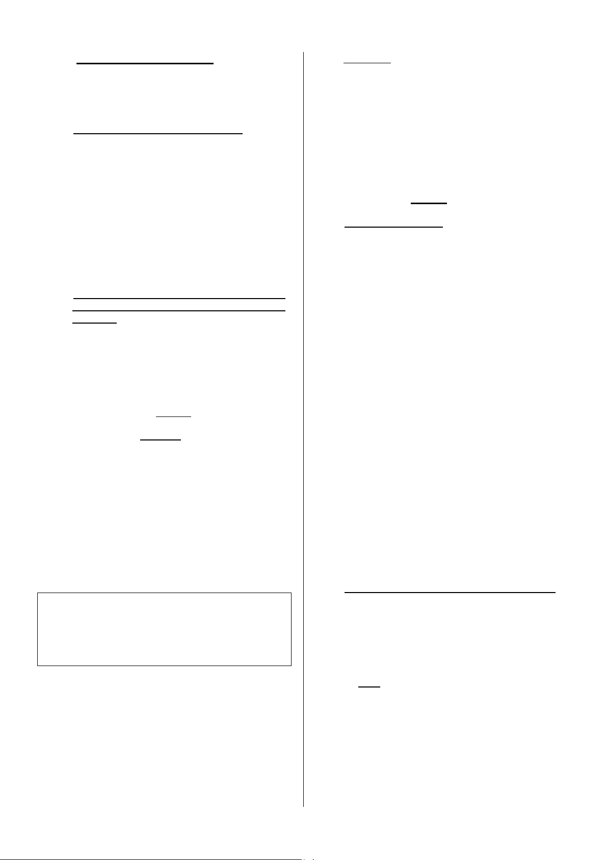
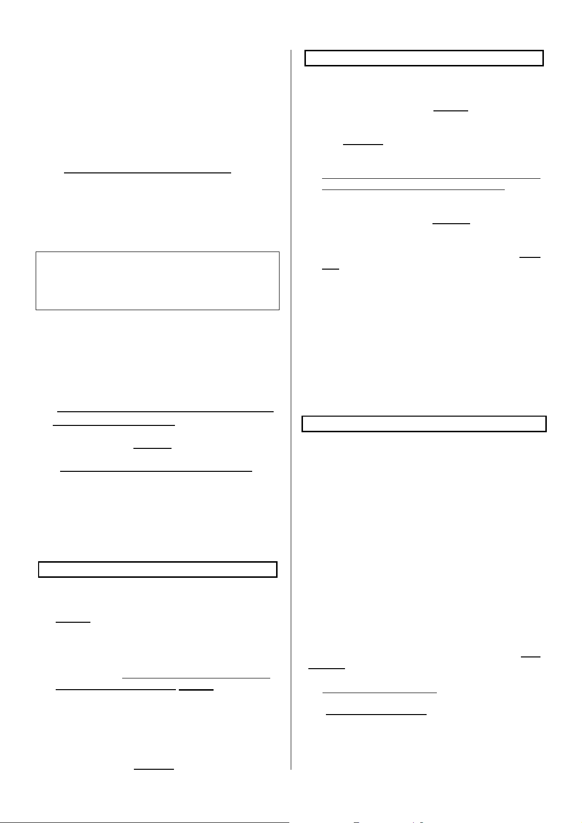
3.2.2 - Minimum flue cross-section
Regulations Operation with doors
closed
Square or rectangular
chimney blocks
Round chimney flues
Minimum cross-section
2.5 dm²
Minimum diameter 153
mm
In all cases, the cross-section of the flue must be at
least equal to that of the connection nozzle on the
appliance.
3.2.3 - A few general recommendations
• In order to remain hot, a good flue should be
made from materials which are poor conductors
of heat.
• The trim surrounding the flue should limit the
outside superficial temperature to :
- 50°C, in inhabited zones.
- 80°C, in uninhabited or inaccessible zones.
• The flue must be perfectly tight, stable and
without internal surface roughness.
• The flue must not present sudden section
variations (slope off vertical less than 45°).
• The flue opening must extend at least 0.4 m
above the ridge of the roof and neighboring roofs
(Fig. 3).
• Two fireplaces must not be connected to the
same flue.
• The flue must enter the room where the fireplace
is to be installed by at least 50 mm.
• Its inside face must be at least 16 cm from all
wood and combustible material (Fig. 3).
• The flue must not have more than two offsets,
that is to say not more than one non-vertical
section.
- Masonry flue :
The angle of the offsets must not exceed 45°
for a total flue height under 5 m. For flue
heights greater than 5 m, the offset angle
must not exceed 20°.
15
Page 16
- Insulated metal flue :
The angle of the offsets must not exceed 45°
with a height limitation of 5 m between the top
and bottom of the offset. The total flue height
is not limited.
• Chimney blocks must be installed with the male
portion facing downward so as to prevent runs
from passing to the exterior.
• All seals, insulation, floor and ceiling
feedthroughs, and firebreak distances must be
performed in strict compliance with DTU 24-2-2.
3.3 - Type and characteristics of the connecting
tube between the fireplace and the flue
• A connecting pipe must be installed between the
appliance and the smoke flue outlet. This flue
must be made with either rigid or flexible dual-fuel
tubing, bearing a favorable "Technical Report" for
direct connection to the closed insert.
It should be noted that it is strictly forbidden to
use aluminum, aluminized steel and galvanized
steel chimney flues.
The following are approved : black plate (min.
thickness 2 mm), enamelled plate (min.
thickness 0,6 mm) and stainless steel (min.
thickness 0,4 mm).
• This flue must be visible over its entire distance
and be able to be mechanically swept. Flue
dilation must not jeopardize upstream and
downstream junction seals nor its mechanical
characteristics or that of the chimney flue. Its
design and particularly the connection with the
chimney flue must prevent the accumulation of
soot, especially during sweeping operations.
• The junctions with fireplace and the chimney flue
must be performed in strict compliance with DTU
24.2.2 and the tube manufacturer specifications,
using all recommended components (fittings,
connections, etc.).
• The connecting tube cross-section must be at
least equal to that of the smoke channel on the
fireplace.
• If the connector is to be horizontal, there should
be an ascending slope of 5 cm per metre.
IMPORTANT :
The area located within a radius of 200 mm around
the connecting tube must be made of incombustible
materials (concrete, bricks).
However, the use of combustible or incombustible
materials which degrade above 90°C is authorized
provided that the surfaces subjected to direct heat
radiation from the connecting tube are heat insulated.
The insulation used must bear an M0 fire rating (rock
wool, ceramic fibers...) (Fig. 4).
3.4 - Draft conditions
• The draft is measured on the connecting tube at
approximately 50 cm after the fireplace's smoke
channel.
• Required draft for proper operation (door
closed) :
- 6 Pa at reduced burn rate (0.6 mm WC).
- 12 Pa at normal burn rate (1.2 mm WC).
• The installation of a draft damper is
recommended. It can be installed :
- Either on the connecting tube, in the tube
cover, above the tube cover shield, in the case
of an outlet at the top.
- Or on the chimney flue, in the case of an
outlet at the rear.
• The damper ensures that the appliance works
properly, even when the draught is considerable
(high flue, piping). The damper should be visible
and readily accessible and installed in the same
room as the stove.
• The damper does not affect stove performance
when the door is open.
3.5 - Ventilation of the room where the fireplace is
installed
• Proper fireplace operation requires air intake in
addition to regulatory air exchange. This air inlet
is mandatory when the residence if equipped with
a mechanical ventilation system.
• The air inlet must draw air directly from the
outside or be located in a room with ventilation to
the exterior and must be protected by a grille.
• The air inlet exhaust must be located as close as
possible to the fireplace. The outlet must be able
to be closed. The user should be able to close it
off when it comes out directly into the room.
While the appliance is being used, make sure
that it is free of any obstructions.
• The cross-section of the air inlet must be at least
equal to the cross-section of the chimney flue
with a minimum of 50 cm² for use with the door
closed only.
• It may be necessary to stop the mechanical
ventilation extractor to avoid smoke being pulled
into the room when the door is opened.
3.6 - Blower electrical connection
• The installation to the fixed 230 V + ground
connection must be made with flexible cable.
• The connection can be made with :
- Either an accessible power outlet.
16
Page 17
- Or a fixed electrical terminal. In this case, the
installation must be fitted with an omnipolar
disconnect device having a contact opening
distance greater than 3 mm.
• The installation must be in compliance with
NFstandard C 15100. In particular, the installation
must be properly grounded (green and yellow
wire).
3.7 - Walls in the vicinity of the appliance
Install the fireplace ready to set up at a minimum 300
mm distance from the side walls of the
accommodation and from any combustible material.
The appliance should be installed on a fire-proof floor.
In order to protect the floor from heat radiation and
possible falling combustible, install the unit on
reflective metal shielding (or on a tiled floor) which
covers the entire surface underneath and in front of
the unit.
The apparatus should be installed on a floor with
sufficient bearing capacity. If an existing building does
not meet this precondition, proper measures should
be taken (for example, the installation of a load
spreading plate) to enable the floor to bear the
apparatus.
4 - INSTALLATION OF THE "READY TO INSTALL"
FIREPLACE (Fig. 5 and 6a)
Screws provided (Fig. 6b)
2 installation configurations are possible :
In both cases, the ceiling shield is placed
60 mm from the ceiling.
To remove the knockouts in the various
shields, simply use a ∅ 6 drill bit to overdrill
the ∅ 2 mm marks.
• CONNECTION ON TOP (FIG 5)
Remove the circular knockouts from the ceiling
and tube cover shields (leave the others in place)
(Fig. 7).
Secure the wall + ceiling shield assembly to the
wall with the 6 screws B, anchors D and nuts C
included in the instruction packet while
maintaining a distance of 60 mm between the
ceiling and the ceiling shield (Fig. 9).
Place the fireplace against the wall.
Fit the tube cover shield onto the connecting tube.
Install the connecting tube.
Secure the tube cover shield to the hood shield
using the sheetmetal screws A supplied in the
instruction packet (Fig. 10).
• CONNECTION AT REAR (FIG 6a)
Remove the circular knockout in the hood shield
and the rectangular knockout in the wall shield.
Leave the others in place (Fig. 8).
Position the fireplace equipped with its connecting
pipe (Fig. 6a).
Slide the wall + ceiling shield assembly into place
(Fig. 9) while maintaining a distance of 60 mm
between the ceiling and the ceiling shield. Locate
the fixation points on the wall.
Only for C07342 : locate the fixation points of the
rectangular pre-cut piece (Fig. 11).
Move the fireplace away from the wall slightly. Fit
the horizontal part of the connecting tube (Fig.
11). Replace the fireplace back against the wall.
Fix the wall screen and the ceiling screen.
Only for C07342 : the wall screen should be fitted
with the rectangular pre-cut piece (4 self-tapping
screws A supplied in the instruction packet ; this
operation is performed when the floor to ceiling
height is greater than 2.4 m).
Place the fireplace against the wall.
Fit the connecting tube to the chimney flue.
Secure the tube cover shield to the hood shield
using the self-tapping screws A supplied in the
instruction packet
• NEXT, IN ALL CASES (FIG. 12) :
- Note the dimension H between the top of the
hood and the ceiling.
- Fit the upper tube cover into the lower tube cover
and adjust to dimension H.
- Drill four ∅ 3.2 holes in the upper tube cover
through the 4 holes located in the upper section
of the lower tube cover.
- Assemble the 2 tube covers with the 4 self-
tapping screws A included in the instruction
packet.
- Spread apart the assembly made of the 2 tube
covers and fit the hood onto the fireplace.
- Secure this assembly onto the hood using 4 self-
tapping screws A, included in the instruction
packet.
Special case where the chimney flue penetrates into
the room at a certain height and whose dimensions
allow its integration into the upper tube cover (see
Fig. 13).
5 - FIREPLACE OPERATION
• This "closed insert" fireplace is a veritable
heating appliance :
- Heigh yield.
- Long-lasting, reduced burn rate operation.
17
Page 18

5.1 - Commissioning
• After first lighting the fire (see paragraph 5.4.1),
burn a moderate fire for the first few hours, by
limiting the load (one ∅15 cm log) and set the air
intake control lever in the middle position (Fig.
14) : this enables the temperature of all chimney
elements to rise progressively and ensures
normal fireplace dilation.
• The smell of paint may be detected initially.
Ventilate the room to limit this discomfort.
• Do not join up the ready to set up to a pipe
already used for other appliances.
5.2 - Combustible
5.2.1 - Recommended combustible
• Hardwood logs with a maximum length of :
- 57 cm for C07342
- 63 cm for C07335
oak, hornbeam, beech, chestnut, etc.
Maximum loading height :
- 20 cm for C07342
- 25 cm for C07335
• We recommend that you use very dry wood with
a maximum moisture content of 20%, or wood
that has been stored under shelter for 2 years
after being cut in order to obtain the best yield
and to prevent the accumulation of creosote in
the flue and on the glass.
• Avoid using resinous wood (pine, fir, spruce...)
which leads to more frequent maintenance of the
fireplace and chimney flue.
5.2.2 - Forbidden combustibles
• All types of fuel except wood are forbidden,
including coal and its derivatives.
• Burning kindling wood, branches, planks, straw,
cardboard, liquid fuels is dangerous and is
forbidden.
• The apparatus should never be used as an
incinerator for waste products.
5.3 - Operation of control devices and
accessories
• Air intake control lever (Fig. 14) : should be
adjusted with the poker.
• Door handle : This must be operated used the
poker (Fig. 15).
• Scraper (Fig. 16) : to remove embers and to
clean the appliance.
Do not burn your hands uselessly. Use the
accessories.
5.4 - Operation
5.4.1 - Lighting a fire
• Set the air intake to normal position (Fig. 14).
• Place some crumpled paper and very dry twigs
on the grate followed by branches of larger
diameter (approximately ∅ 3 to 5 cm).
• Light the paper and close the door (or leave the
door slightly open to accelerate the blaze).
• Once the "kindling wood" load is burning, open
the door, load the appliance with the
recommended fuel and use the regulation
devices to obtain the burning required.
5.4.2 – Operation
5.4.2.1 - Periodic and continuous use
• The intermittent use of the appliance requires a
reload every 45 minutes.
This type of use is particularly recommended as it
environmentally friendly.
• The apparatus may also be used in continuous
mode when periodic use is not possible or when
reduced burning is required. In this case,
maximum heat output can be maintained for 3
hours and with a slow combustion rate, and a low
heat output, the burning period can extend to 10
hours with a 10 kg load for C07342, 13 kg for
C07335.
The nominal power in intermittent use :
• Obtained with a 12 Pa draft, with a wood load of :
o 3,3 kg for C07335
o 2,4 kg for C07342
as a hard wood and non-split log.
• Reload every 45 minutes on glowing embers :
o 0,5 kg for C07335
o 0,4 kg for C07342
(i.e. 3 cm thickness) with the air intake set to
maximum position.
• The announced power is the average power
obtained with each 45 minute-load.
The nominal power in continuous use :
• Obtained with a 12 Pa draft, with a wood load of :
o 13 kg for C07335
o 10 kg for C07342
made up of 2 hard wood and non split logs.
• Reload every 3 hours on glowing embers :
o 0,5 kg for C07335
o 0,35 kg for C07342
(i.e. 3 cm thickness) with the air intake set to
maximum position.
• The burning power given is the average burning
power obtained with each 3 hours load.
Slow combustion, autonomy greater than 10 hours in
continuous use :
• Obtained with a 6 Pa draft, with a wood load of :
o 13 kg for C07335
o 10 kg for C07342
made up of a hard wood and non-split log
(preferably logs more than 16 cm in diameter).
18
Page 19
• Reload on glowing embers of approximately :
o 0,5 kg for C07335
o 0,3 kg pour C07342
(i.e. 3 cm thickness) with the air intake set to
close position.
5.4.2.2 -
Fire duct
• The desired burn rate is obtained by moving the
air intake control lever (see paragraph 5.3) and
by selecting a load in relation to your specific
needs :
- For maximum heating, load the fireplace with
3 logs measuring approximately 10 cm in
diameter (air intake set to normal position)
(Fig. 14).
Use this position only temporarily, to heat the
rooms following prolonged absence.
- For an intermediate burn rate, reduce the
load : one or two logs (air intake set to middle
position) (Fig. 14).
- For a long-lasting heat output with a slow
combustion rate, use 1 or 2 non-split logs with
a diameter superior to 15 cm (air intake set to
close position) (Fig. 14).
• To get a long-lasting combustion rate, reload on a
merely burning bed of embers.
• For rapid restarting of the fire, add some kindling
wood, load the logs, and only if necessary keep
the door partly open for several minutes, without
leaving the appliance unattended. Thereafter, use
the controls as per the instructions (paragraph
5.4). Doing so will accelerate the fire's recovery,
particularly if the wood is damp.
• Make burn rate changes (passing from a normal
to a reduced burn rate, for example) before
reloading the fireplace during the "live coals"
combustion phase, in order to allow the fireplace
and the chimney flue to adapt progressively to the
change.
• To avoid smoke and falling ash coming out into
the room during reloading operations, the door
should be opened with the following precautions :
- Open the door partly, waits for the open door
suction to start, and open the door slowly.
• Using the stove in continuous mode and a slow
combustion rate, especially in milder temperature
conditions (bad draught) and with wet timber,
leads to an incomplete combustion and the
formation of tar and soot deposits :
- Alternate operation with periods of slow
burning and normal burning.
- Burning small loads is recommended.
• After the stove has been used in slow combustion
mode, the front glass may darken because of a
slight soot deposit, this deposit will burn off (by
pyrolysis) with the next hot fire (higher
combustion rate).
The fitting of a suction moderating flap in the
connecting duct enables to control the burning,
notably slow burning, enabling long lasting
heating.
5.4.2.3 – Set fan (only for C07342)
- DESCRIPTION
(Fig. 24)
The blower unit includes the following :
- a box
- a fan support with a 230 V 50 Hz 30 W
motor fan
- a fan shield
- a selector with two speeds and stop
For the versions with thermostat :
- a thermostat which sets in motion the
ventilator in accordance with the fireplace's
temperature, if the selector is in position I
or II.
- a selector AUTO/MANU
- UTILIZATION
Select a speed of ventilation :
. Little speed, selector in position I
. High speed, selector in position II
Put in heating the apparatus (see the handbook
Fireplace / Insert).
For the versions with thermostat, select automatic
operation (AUTO) or manual operation (MANU)
with the selector :
- In the MANU position : the fan is switched on
and off by manual control. In this position, the
blower function can be started up immediately
and must be switched off by hand.
- In the AUTO position : the fan is operated
automatically, when the whole of the apparatus is
warm, generally during the following hour the
lighting. Its running is interrupted when the
apparatus is cold, generally at the fireplace's
extinction.
If you want the blower to be started up immediately
and then switched off automatically, select the MANU
position when lighting and then switch to the AUTO
position once the appliance is hot. The blower will
then be switched off automatically.
5.4.2.4 - Ash removal
• The air used for the combustion of the wood
arrives underneath the grate when the air intake
control lever is open. This air is also used to cool
the grate. To ensure optimum performance and
to avoid damaging the grate due to overheating, it
is very important that it not be obstructed. The
grate should therefore be cleaned regularly and
the ashes removed.
• Use the scraper to de-ash the grating (Fig. 16).
19
Page 20
Extracting the ash box.
- Open the ash box door, pull the ash box and
grab it by the handle.
• Remove periodically any ash which spilled
accidentally in the ash box compartment.
• The ash pan, located under the grate, is easily
removed by pulling it out with the poker.
The level of ashes must never reach
the cast iron grate : de-ash every 2 to 3 days.
5.4.2.5 - Safety rules
• Never dowse the fire with water to put it out.
• The front glass as well as other parts of the stove
are very hot : be aware of the risk of burns,
particularly when small children are present.
• The fireplace radiates a significant amount of
heat even through the glass : do not place heatsensitive materials or objects at a distance closer
than 1.50m from the glass.
• Empty the ash pan into a metal or nonflammable
container intended for this purpose. Although the
ashes may appear to be cold, they may still be
very hot even after a long cooling-down period.
• Do not place easily inflammable materials near
the fireplace or in the woodbox.
• Cautious, do not store the firewood under the
appliance (Fig. 17).
• In case of fire in the flue, set the air intake to
close position.
6 - MAINTENANCE AND SWEEPING
INSTRUCTIONS
6.1 - Maintenance and sweeping of the chimney
flue
• The chimney flue must be mechanically swept.
This operation should be performed several times
per year and at least once during the heating
season. A certificate should be handed in by a
qualified professional.
• Prior to sweeping operations :
- Dismount the deflector (Fig. 18, 19, 20) :
. dismount the deflector (lift the deflector 1,
- Remove the hearth back panel and the
connecting pipe.
- For reinstall the deflector, carry out the same
operations in the reverse order.
move it forward 2, tilt the rear 3, lower it
4 and remove it 5 through the righthand side).
- Thoroughly inspect the condition of the
fireplace and all seals, in particular : seals,
locking mechanisms, bearing surfaces (door,
frame).
- After removing the tube cover :
. Thoroughly inspect the condition of the
chimney flue and the connecting tube: all
connections must be mechanically sound
and retain their tightness.
. Use a vacuum cleaner to clean the
convection circuit around the fireplace,
inside the hood and in the hot air outlets.
- Clean the appliance using a brush and a
vacuum cleaner.
If an anomaly is detected, have the unit or the
installation repaired by a certified professional.
After a long off-period :
- Check that nothing obstructs any pipes before
using the stove again.
6.2 - Routine maintenance
• Clean the glass with a damp cloth and remove
the ash. If necessary, use a special cleaning
product in accordance with the manufacturer's
instructions. Wait until the installation has
completely cooled down before performing this
operation.
• Clean regularly the ventilation guides (Fig. 21) :
-
Using the tip of a metallic object (2), scratch
the inner edges of the cast iron to remove the
soot which may have formed.
- Using a vacuum cleaner (1), remove the
particles and dust trapped between the door
and window (Fig. 22).
NOTE : The particles disrupt the formation of the
secondary air layer which protects the glass
from direct contact with the smoke and
assists in the complete combustion of the
wood.
These operations should be performed whenever
the glass is dirty and only once the fireplace has
completely cooled down.
• Check that the door catch operates correctly and,
if necessary, make the adjustments (see
paragraph 6.2.1) :
• Regularly clean the hot air outlets on the tube
cover. The outlets become quickly obstructed
with intensive operation. Select an adequate
cleaning interval.
• If servicing of the blower is necessary for any
reason whatsoever :
20
Page 21

- For C07342 (Fig. 26) :
. Dismantling of the ventilator support
Slightly unscrew the three screws
and remove the joint support .
Remove the 2 fixing screws of the
blower.
Take the blower out by pulling the grid.
. Reassembling the blower.
Proceed in the reverse order to the
dismantling.
. Electric diagram (Fig. 27)
6.2.1 - Adjusting the door closing mechanism
• Tighten door closure : (Fig 23)
- Alternately loosen screw (1) and tighten screw
(2).
- Turn each screw 1/4 turn and repeat the
operation as required.
NOTE : This operation increases the pressure on
the fireplace door seal.
• Loosen door closure : (Fig 23)
- Alternately loosen screw (2) and tighten screw
(1).
- Turn each screw 1/4 turn and repeat the
operation as required.
NOTE : This operation reduces the pressure on
the fireplace door seal.
21
Page 22

7 – GLOBAL TERMS OF WARRANTY
1. TERMS AND CONDITIONS
Apart from the legal warranty, particularly for latent defects, Deville guarantees to deliver the furniture in case of
obvious defects or non-conformity to the ordered furniture.
Without prejudice to the provisions that are to be taken concerning the carrier, claims on delivery of furniture
concerning the obvious defects or the non conformity, must be issued by the Buyer in writing a registered letter
with confirmation of receipt to Deville company with in 5 days after noticing the defect. It is up to the Buyer to
prove the reality of the noticed defects and irregularities. The Buyer must let Deville every opportunity of noticing
any of those defects and irregularities in order to salve then.
The Buyer must also keep the non standard supplies at the disposal of Deville, according to the instructions of
the latter. Prior to any return of supplies an agreement will be issued.
2. EXTEND
The warranty of Deville covers, except for any compensation or for damages, the free replacement or repairing
of supplier the part acknowledged as being defected (except for wear and tear parts) by its services to the
exclusion of the fees for the workplace, for the removal and for the shipping.
On enamelled equipments, appliances, crackles are never considered as a manufacturing defect. They are due
to the difference of expansion of iron enamel or cast-iron enamel and don’t alter the adherence.
Paid replacement parts are warranted for a six-month period from the invoicing date, any additional warranty
agreed by a retailer from Deville doesn’t commit Deville. Whenever claiming under a warranty, the guarantee
with the stamp from the retailer Deville is strictly required. The above guarantee must be produced for any
demand to repair the appliance under warranty, or a detachable slip or coupon of any such guarantee must,
according to the own organisation of Deville, be returned to the latter within the required time. For lack of this,
the date on the invoice issued by Deville can’t be taken into account. The interventions under warranty can’t
have the effect of continuing the warranty.
3. WARRANTY PERIOD
The agreed warranty period assured by Deville is the longer of 1 year from the day of the purchase of the
appliance, subject to the above terms and conditions are fact that the claims covered by the conditions are
requested within the required time. The repairing, the replacement or the alteration of parts under the warranty
period can neither have the effect of continuing the period of the latter, not get to any compensation for any
fees, for late delivery, accidents or any such damages.
4. EXCLUSION
The warranty is unavailable for the following cases, without this list being exhaustive :
- Fitting out, fitting out and assembling of appliances not due to Deville.
- Consequently Deville can’t be considered as responsible for damages or supplies, or accidents
to persons due to local laws and regulations ( for example the fact that there is no linking to the a
earth ground connection, or a wrong drought of a fitting out ).
Fair wear and tear of the supplies or abnormal use of the supplies including the case of industrial or trading use
or a use of the supplies in different conditions from the ones it was built for. It is, for example, of non respect of
the conditions described in the directions issued by Deville : display to outside conditions damaging the
appliance ; such as excessive dampness or abnormal change of the electrical tension. Malfunction, damage or
accident due to a shock, a drop, a carelessness, a failure of supervision or of service from the Buyer.
Any alteration, change or intervention made by a member of the staff or a company that is not approved by
Deville, or manufactured with replacement parts that are not genuine or not approved by the manufacturer.
5. SPECIAL TERMS OF WARRANTY
These terms add and define the above general terms of warranty and come first to the former, refer to the
enclosed leaf untitled : “special terms of sales Deville - warranty”.
22
Page 23

INHALT
INHALT
INHALTINHALT
1
1 ---- VORWORT
VORWORT ................................
1 1
VORWORT VORWORT
2
2 ---- EIGENSCHAFTEN DES GERÄTS
EIGENSCHAFTEN DES GERÄTS................................
2 2
EIGENSCHAFTEN DES GERÄTS EIGENSCHAFTEN DES GERÄTS
2.1 - Bezeichnung
2.2 - Nennwert der Heizleistung und Heizdauer bei Sparbetrieb
2.3 - Beschreibung
2.4 - Raumbedarf
2.5 - Umgebung
3
3 ---- EIGENSCHAFTEN DER INSTALLATION, AN DER DAS GERÄT
EIGENSCHAFTEN DER INSTALLATION, AN DER DAS GERÄT
3 3
EIGENSCHAFTEN DER INSTALLATION, AN DER DAS GERÄT EIGENSCHAFTEN DER INSTALLATION, AN DER DAS GERÄT
ANGESCHLOSSEN WERDEN KANN
ANGESCHLOSSEN WERDEN KANN................................
ANGESCHLOSSEN WERDEN KANN ANGESCHLOSSEN WERDEN KANN
3.1 - Bezeichnung der verschiedenen Teile des Rauchgas-Abführungssystems
3.2 - Art und Abmessungen des Schornsteins, an dem das Gerät angeschlossen
werden muß
3.2.1 - Art des Schornsteins
3.2.2 - Mindestquerschnitt
3.2.3 - Einige allgemeine Empfehlungen
3.3 - Art und Abmessungen des Anschlußrohrs des Geräts zum Schornstein
3.4 - Bedingungen für richtigen Zug
3.5 - Lüftung des Raums, in dem das Gerät installiert ist
3.6 - Elektrischer Anschluß des Gebläses
3.7 - Art der Mauern und Wände in der Nähe des Geräts
4
4 ---- INSTALLATION DE
INSTALLATION DES "EINBAUFERTIGEN KAMINS "
4 4
INSTALLATION DE INSTALLATION DE
................................................................
................................................................
S "EINBAUFERTIGEN KAMINS "................................
S "EINBAUFERTIGEN KAMINS "S "EINBAUFERTIGEN KAMINS "
................................................................
................................................................
................................................................
................................................................
................................................................
................................................................
..........................................
................................................................
.......................................
................................................................
.......................................
................................................................
..................................
................................................................
5
5 ---- VERWENDU
VERWENDUNG DES GERÄTS
5 5
VERWENDU VERWENDU
5.1 - Anzünden des ersten Feuers
5.2 - Brennstoff
5.2.1 - Empfohlene Brennstoffe
5.2.2 - Verbotene Brennstoffe
5.3 - Verwendung der Bedienungen und des Zubehörs
5.4 - Anwendung
5.4.1 - Anzünden
5.4.2 - Betrieb
6
6 ---- RATSCHLÄGE FÜR RE
RATSCHLÄGE FÜR REINIGUNG UND INSTANDHALTUNG
6 6
RATSCHLÄGE FÜR RE RATSCHLÄGE FÜR RE
6.1 - Fegen und Instandhaltung des Schornsteins
6.2 - Laufende Instandhaltungsmaßnahmen
6.2.1 - Einstellung des Türverschlusses
7
7 –––– ALLEGEMEINE GARANTIEBEDINGUNGEN
ALLEGEMEINE GARANTIEBEDINGUNGEN ................................
7 7
ALLEGEMEINE GARANTIEBEDINGUNGEN ALLEGEMEINE GARANTIEBEDINGUNGEN
NG DES GERÄTS................................
NG DES GERÄTSNG DES GERÄTS
INIGUNG UND INSTANDHALTUNG................................
INIGUNG UND INSTANDHALTUNGINIGUNG UND INSTANDHALTUNG
................................................................
................................................................
......................................................
................................................................
...........................................
................................................................
................................ 31
................................................................
...................... 3
............................................
....... 24
24
..............
24 24
....... 24
24
..............
24 24
.. 25
25
....
25 25
.......... 27
....................
........... 28
......................
27
27 27
28
28 28
31
31 31
32222
3 3
23
Page 24
ACHTUNG
ACHTUNG :
ACHTUNG ACHTUNG
:
ZUR VERMEIDUNG JEGLICHER BRANDGEFAHR MUSS DIESES GERÄT FACHGERECHT
: :
GEMÄSS DEN IN DER VORLIEGENDEN ANLEITUNG GENANNTEN TECHNISCHEN VORSCHRIFTEN
INSTALLIERT WERDEN.
DIESES GERÄT MUß UNTER BEACHTUNG GELTENDER TECHNISCHER VORSCHRIFTEN INSTALLIERT
WERDEN. ES WIRD EMPFOHLEN, DIE INSTALLATION DURCH EINE FACHKRAFT DURCHFÜHREN ZU
LASSEN.
Wir empfehlen, die vorliegende Anleitung vollständig und aufmerksam durchzulesen, um diesen Kamin von
DEVILLE optimal und zufriedenstellend zu betreiben.
Alle ortlichen und nationalen vorschriften sowie die europaischen normen mussen bei der benutzung des
gerates beachtet werden.
Werden die Anleitungen für Montage, Installation und Gebrauch nicht eingehalten, so ist die ausführende
Person für eventuelle Folgen verantwortlich. Das Gerät darf nicht abgeändert werden.
1 - VORWORT
• Die "einbaufertigen" Kamine werden wie ein
Holzofen installiert. Die Installation erfolgt nach
den gleichen Regeln, insbesondere hinsichtlich :
- Art des für diesen Verwendungszweck
erforderlichen Schornsteins und die
Anforderungen für dessen Benutzung,
- Anschluß des Geräts am Schornstein,
- Lüftung des Raums, in dem das Gerät
aufgestellt wird.
• In Kapitel 4 werden die speziell den
"einbaufertigen" Kamin betreffenden Fragen
behandelt :
- Aufstellung gegen eine Wand.
- Höheneinstellung.
• Achtung, die einbaufertigen Kamine erlauben
keinen Anschluss von WarmluftAusgangskanälen: die Sicherheit der Umgebung
ist nicht mehr gewährleistet, wenn die
Schutzschirme der Wand, an der der Kamin
angebaut ist, geändert (durchbohrt, verschoben,
usw.) werden.
• Wir erinnern im im Folgenden an die
einzuhaltenden grundlegenden Empfehlungen.
Die technischen Vorschriften DTU 24-2-2 und
24.1 beschreiben in kompletter Weise die
notwendigen Anordnungen bezüglich der
Rauchgas-Abführung und der Zuleitung von
Frischluft.
• Die aufbaufertigen Kamine C07335 und C07342
entsprechen der französischen Norm NF EN
13240.
2 - EIGENSCHAFTEN DES GERÄTS
2.1 – Bezeichnung
Die "einbaufertigen" Kamine sind fortgesetzt
arbeitende Heizgeräte. Die Verbrennung des
ausschließlich benutzten Brennstoffs Holz erfolgt auf
einem Gitter in einer halbgeschlossenen
Brennkammer. Das Gerät ist für den Anbau gegen
eine Wand vorgesehen, wobei keine zusätzlichen
Schutzmaßnahmen erforderlich sind.
2.2 - Nennwert der Heizleistung und
bei Sparbetrieb
• Der Nennwert der Heizleistung entspricht der
Norm NF EN 13240 bei einer Prüfung bei
normalem Betrieb :
Leistung Zug Rauchmassenstrom Rauchtemperatur
C07335 14 kW 12 Pa 10,5 g/s 321°C
C07342 10 kW 12 Pa 10,5 g/s 299°C
- Diese Leistung wurde bei einem Zug von 12 Pa
mit einer Ladung von 10 kg Holz für C07342 und
14 kg Holz für C07335 erhalten. Die Holzladung
bestand aus drei nicht gespaltenen
Rundstücken.
- Die genannte Leistung ist die bei dieser Prüfung
während 3 Stunden erhaltene mittlere Leistung.
- Um dieses Ergebnis zu erhalten, das Holz :
. Bei den Modellen C07342 auf etwa 300 g,
das heißt etwa 3 cm dicke Glut auflegen.
. Bei den Modellen C07335 auf etwa 500g,
genügen 4 cm Glut.
Der Luftzufuhr-Schieber muß hierbei maximal geöffnet
sein.
• Eine längere Heizdauer von über 10 Stunden bei
Sparbetrieb kann mit einer vollen Ladung bei
vollständigem Schließen des Schiebers der
Luftzufuhr erhalten werden.
2.3 - Beschreibung (Abb. 1)
• Das Gerät besteht aus einem Feuerraum und
aus einer für Wärmeaustausch und Verkleidung
sorgenden Baugruppe. Er wird in 2 Paketen
geliefert.
• Die wesentlichen Bauteile des Feuerraums sind
in Abbildung 1 gezeigt und aufgelistet :
- Der Feuerraum besteht aus 4 mm dickem
Stahl. Vor der Rückwand ist eine gußeiserne
Kaminplatte eingesetzt.
- Die Türen sind aus Gusseisen und mit
Abdichtungen versehen.
- Kann mittels des im unteren Teil der Tür
gelegenen Luftzufuhr-Schiebers die Stärke des
Feuers eingestellt werden.
Heizdauer
24
Page 25
- Im oberen Teil der Verglasung ist eine
zusätzliche Luftzufuhr angebracht. Diese soll
beim Sauberhalten der Scheibe helfen und
eine vollständigere Verbrennung des Holzes
gewährleisten.
- Der aufbaufertige Kamin C07342 ist mit einem
2 Geschwindigkeits -gebläse ausgestattet,
dadurch wird die Luftkonvektion um den Ofen
beschleunigt.
• Nettogewicht des Geräts :
C07335 140 kg
C07342 180 kg
Zur Handhabung des Geräts die Tür(en) und die
verschiedenen im Feuerraum befindlichen
gusseisernen Teile entfernen.
2.4 - Raumbedarf (Abb. 2)
2.5 - Umgebung (Abb. 2)
• Das Gerät muß gegen eine Wand installiert
werden. Die verstellbare Rohrabdeckung
ermöglicht es, die Höhe des Geräts der Höhe der
Decke anzupassen.
• Der mit dem Gerät gelieferte Abschirmsatz
besorgt den Schutz vor Wärmestrahlung und
leitet die zur Kühlung der Hauswände
umlaufende Luft. Er muß unbedingt unter
Beachtung der nachstehenden Angaben
installiert werden
• Das Gerät muß unbedingt, wie in Abschnitt 3.3
gezeigt, mittels eines Anschlußrohrs (∅ 180 mm
für C07335, ∅ 153 mm für die Kamine C07342)
am Schornstein angeschlossen werden.
3 - EIGENSCHAFTEN DER INSTALLATION, AN
DER DAS GERÄT ANGESCHLOSSEN WERDEN
KANN
3.1 - Bezeichnung der verschiedenen Teile des
Rauchgas-Abführungssystems (Abb. 3)
3.2 - Art und Abmessungen des Schornsteins, an
dem das Gerät angeschlossen werden muß
3.2.1 - Art des Schornsteins
3.2.1.1 - Fall eines neuen Schornsteins
• Verwendung folgender Materialien :
- Kaminbauformsteine aus gebranntem Ton
gemäß NF P 51-311.
- Kaminbauformsteine aus Beton gemäß NF P
51-321.
- Metallene Verbundrohre gemäß NF D 35-304
und NF D 35-303 oder gemäß technischer
Prüfung für diesen Verwendungszweck
zugelassen.
- Gebrannte Tonsteine gemäß NF P 51-301.
- Feuerfeste Steine gemäß NF P 51-302.
• Durch die Verwendung bereits vorgefertigter
Teile wird der Einbau einer Isolierung an der
Baustelle, insbesondere für die Wände des
Schornsteins an der Durchführung durch
Dachboden und Dach vermieden (minimaler
Wärmedurchlaßwiderstand : 0,43 m² k/W).
3.2.1.2 - Fall eines existierenden Schornsteins
•
Der Installateur übernimmt die Verantwortung
für die vorhandenen Teile. Er muß den Zustand
des Schornsteins überprüfen und die für den
richtigen Betrieb und die Einhaltung der
bestehenden Vorschriften notwendigen Arbeiten
durchführen.
• Den Schornstein fegen und dann im Rahmen
einer ernsthaften Überprüfung folgendes
sicherstellen :
- Eignung des Schornsteins für die
vorgesehene Benutzung,
- Stabilität,
- Abwesenheit den Abzug behindernder
Fremdkörper und Dichtigkeit (Anhang II der
technischen Vorschrift 24-1).
• Falls der Schornstein nicht kompatibel ist, gemäß
einem technisch zugelassenen Verfahren in
dessen Innern eine Rohrleitung einführen oder
einen neuen Schornstein errichten.
3.2.2 - Mindestquerschnitt
Vorschrift
Quadratische oder
Rechteckige
Kaminbauformsteine
Kreisförmige Rohre
Betrieb bei geschlossenen
Türen
Mindestquerschnitt 2,5 dm²
Mindestdurchmesser 153 mm
In allen Fällen muss der Querschnitt des Rohrs
mindestens gleich demjenigen der auf dem Gerät
befindlichen Anschlussmuffe sein.
3.2.3 - Einige allgemeine Empfehlungen
•
Ein guter Schornstein muß, um seine Wärme
beibehalten zu können, aus schwach
wärmeleitenden Materialien gebaut sein.
•
Die Verkleidung des Schornsteins muß eine
Begrenzung der äußeren Oberflächentemperatur
auf folgende Werte ermöglichen :
-
50° C, in den bewohnbaren Bereichen.
-
80° C, in nicht bewohnbaren oder unzugänglichen
Bereichen.
•
Ein Schornstein muß vollkommen dicht, glatt und
stabil sein.
•
Er darf keine abrupten Querschnittsänderungen
aufweisen. Er muß um weniger als 45° zur
Senkrechten geneigt sein.
•
Seine Ausgangsöffnung muß mindestens 0,4 m
oberhalb des Dachfirsts und der benachbarten
Dächer liegen (Fig. 3).
25
Page 26

•
Zwei Heizgeräte dürfen nicht am gleichen
Schornstein angeschlossen werden.
•
Seine Ausgangsöffnung muß mindestens 50 mm
in dem Raum, in dem das Heizgerät installiert
wird, eintreten.
•
Seine Innenfläche muß mindestens 16 cm von
Holz oder anderen brennbaren Materialien
entfernt sein (Fig. 3).
•
Der Schornstein darf nicht mehr als zwei
Ablenkungen (nur einen nicht senkrechten
Abschnitt) aufweisen.
- Bei einem gemauerten Schornstein :
Der Winkel darf bei 5 m Gesamthöhe des
Kamins 45° nicht übertreffen. Bei Kaminen
größerer Höhe als 5 m ist der Winkel von
Richtungsänderungen auf 20° begrenzt.
- Bei isoliertem Metallrohr :
Der Winkel von Richtungsänderungen darf 45°
nicht übertreffen, wobei die Höhe zwischen
der unteren und der oberen Ablenkungsstelle
nicht länger als 5 m sein darf Die Gesamthöhe
des Rohrs ist unbegrenzt.
• Die Kaminbauformsteine müssen mit der
vorstehenden Seite nach unten und der vertieften
Seite nach oben zusammengesetzt werden, um
sicherzustellen, daß nichts nach außen abfließen
kann.
• Die Abdichtung, die Isolierung, die
Durchführungen durch Decken und die Abstände
zum Feuer müssen genau der technischen
Vorschrift DTU 24-2-2 entsprechen.
3.3 - Art und Abmessungen des Anschlußrohrs
des Geräts zum Schornstein
• Zwischen dem Feuerraum-Einsatz und dem
Eingang des Schornsteins muß eine
Anschlußverbindung installiert werden. Diese
Verbindung ist mittels eines starren oder
biegsamen, für unterschiedliche Brennstoffe
geeigneten Rohrs durchzuführen. Die Eignung
dieses Rohrs für Direktanschluß an einem
geschlossenen Feuerraum muß bescheinigt sein.
Folgende Materialien sind verboten : Aluminium,
aluminiumbeschichteter oder verzinkter Stahl.
Folgende Materialien sind zugelassen :
Schwarzblech (Mindestdicke 2 mm), emailliertes
Blech (Mindestdicke 0,6 mm) und nichtrostender
Stahl Mindestdicke 0,4 mm).
• Dieses Rohr muß auf seiner ganzen Länge
sichtbar sein und mit einer mechanischen
Vorrichtung gefegt werden können. Seine
thermische Ausdehnung darf die Abdichtungen
an seinen Ein- und Ausgangsöffnungen, sowie
seine Widerstandsfähigkeit und die des
Schornsteins nicht beeinträchtigen.
Es muß so gebaut sein, insbesondere bezüglich
seines Anschlusses am Schornstein, daß
Rußansammlungen verhindert werden, vor allem
beim Kaminfegen.
• Die Verbindungen zum Heizgerät und zum
Schornstein müssen unter strenger Einhaltung
der technischen Vorschrift DTU 24.2.2 und der
Spezifikationen des Rohrherstellers, unter
Verwendung aller vorgeschriebenen Bauteile
(Ansätze, Verbindungsstücke, usw...) erfolgen.
• Der Querschnitt des Anschlußrohrs muß
mindestens so groß sein, wie der Querschnitt der
Ausgangsöffnung des Kamins.
• Falls das Rohr horizontal verlegt ist, muß eine
leichte Steigung von 5 cm pro Meter verbleiben.
ACHTUNG :
Innerhalb eines Abstands von 200 mm um das
Anschlußrohr muß die Fläche aus nicht
brennbarem Material bestehen (Beton,
Ziegelsteine). Die Verwendung brennbarer
Materialien oder unbrennbarer, die sich oberhalb
90°C verschlechtern, ist jedoch zugelassen, falls
die der direkten Wärmestrahlung des
Anschlußrohrs ausgesetzten Flächen thermisch
isoliert werden. Das verwendete Isoliermaterial
muß von mineralem Typ sein (Steinwolle,
Keramikfasern, usw.) (Abb. 4).
3.4 - Bedingungen für richtigen Zug
• Der Zug wird am Anschlußrohr in einem Abstand von
etwa 50 cm von der Ausgangsöffnung des Geräts
gemessen.
• Für richtigen Betrieb bei geschlossener Tür
erforderlicher Zug :
- 6 Pa bei Sparbetrieb (0,6 mm Wassersäule).
- 12 Pa bei normalem Betrieb (1,2 mm
Wassersäiule).
•
Der Einbau eines Zugregulators wird empfohlen.
Dieser kann an folgenden Stellen eingebaut
werden
:
- Auf dem Anschlußrohr, in der Rohrabdeckung
und über dem Schirm der Rohrabdeckung,
falls der Anschluß auf dem Gerät erfolgt,
- Auf dem Schornstein beim Anschluß auf der
Rückseite des Geräts.
•
Mit Hilfe eines Zugregulators kann auch bei
Vorliegen eines sehr starken Zuges (sehr hoher
Schornstein, Rohr) ein ordentlicher Betrieb
sichergestellt werden. Der Regulator muß leicht
sichtbar und zugänglich sein und im gleichem
Raum, in dem der Ofen aufgestelt ist, eingebaut
werden.
•
Bei geöffneter Tür hat die Klappe des
Zugregulators keinen Einfluß auf die Arbeitsweise
des Geräts.
3.5 - Lüftung des Raums, in dem das Gerät
installiert ist
26
Page 27
• Beim Betrieb des Geräts ist eine stärkere
Luftzufuhr erforderlich, als die zur Erneuerung
der Raumluft vorgeschriebene Zufuhr. Diese
Luftzuführung ist Pflicht, wenn die Wohnung mit
einer mechanischen Lüftung ausgestattet ist.
• Der Eingang der Luftzufuhr muß entweder direkt
an der Außenwand oder in einem von außen
gelüfteten Raum angebracht sein. Er muß durch
ein Gitter geschützt werden.
• Der Ausgang der Luftzufuhr muß so nahe wie
möglich am Gerät austreten sein. Er muß
verschließbar sein, wenn er direkt in das Zimmer
eintritt. Versichern Sie sich, dass das Gerät in
Betrieb von nichts verschlossen wird.
•
Der Querschnitt der Luftzufuhröffnung muß
mindestens ein Viertel des Querschnitts des
Schornsteins, auf jeden Fall jedoch 50 cm²
betragen, bei ausschließlicher Verwendung mit
geschlossener Tür.
• Ein Abschalten des Absauggebläses der
mechanischen Lüftung kann sich als erforderlich
erweisen, um beim Öffnen der Tür ein
Zurückströmen der Rauchgase in das Zimmer zu
vermeiden.
3.6 - Elektrischer Anschluß des Gebläses
• Der feste Anschluß an 230 V + Erdung muß mit
Hilfe des biegsamen Kabels durchgeführt
werden.
• Er kann auf eine der folgenden Arten hergestellt
werden :
- Anschlußstecker, welcher zugänglich bleiben
muß.
- Anschluß an festen Klemmen, wobei die
Installation mit einem alle Pole
unterbrechenden Trennschalter ausgestattet
sein muß. Bei offenem Trennschalter müssen
die Kontakte mehr als 3 mm voneinander
entfernt sein.
• Die Installation muß der Norm NFC 15100
entsprechen. Es muß insbesondere der Anschluß
des Erdleiters (grün-gelber Draht) hergestellt
werden.
3.7 - Art der Mauern und Wände in der Nähe des
Geräts
Stellen Sie den einbaufertigen Kamin mindestens 300
mm entfernt von Wänden und jeglichen brennbaren
Materialien auf.
Das Gerät muss auf einem nicht brennbaren
Untergrund installiert werden.
Zum Schutz des Bodens gegen abgestrahlte Wärme
und eventuell heraus fallenden Brennstoff ist das
Gerät auf einem reflektierenden Metallschirm, der die
gesamte unter und vor dem Gerät gelegene Fläche
überdeckt, abzustellen (oder auch auf einer mit
Fliesen belegten Fläche).
Das Gerät muss auf einem ausreichend tragfähigen
Untergrund aufgebaut werden. Falls die bestehende
Konstruktion diesen Bedingungen nicht entspricht,
müssen entsprechende Maßnahmen getroffen
werden (z.B. die Installation eines Brettes zur
Verteilung des Gewichts).
4 - INSTALLATION DES "EINBAUFERTIGEN
KAMINS" (Abb. 5 und 6a)
Gelieferter Schraubensatz (Abb. 6b)
2 Möglichkeiten :
In beiden Fällen befindet sich die
Abschirmung zur Decke in einem Abstand
von 60 mm von der Decke.
Zum Entfernen der in den verschiedenen
Abschirmungen vorhandenen vorgestanzten
Öffnungen genügt es, mit einem 6-mmBohrer an den 2-mm-Vertiefungen jeweils
ein Loch zu bohren.
• ANSCHLUSS VON OBEN (ABB 5)
Die vorgestanzten runden Abschnitte in der
Abschirmung zur Decke und der Abschirmung der
Rohrabdeckung entfernen (die anderen eingesetzt
lassen) (Abb. 7).
Die aus Abschirmung zu Wand und Decke
bestehende Einheit mit den 6 Schrauben B,
Dübeln D und Scheiben C, die in dem Beutel mit
der Anleitung enthalten sind, an der Wand
befestigen. Dabei muß ein Abstand von 60 mm
zwischen der Decke und der Abschirmung
eingehalten werden (Abb. 9).
Das Gerät gegen die Wand stellen.
Die Abschirmung der Rohrabdeckung über das
Anschlußrohr schieben.
Das Anschlußrohr einsetzen.
Die Abschirmung der Rohrabdeckung auf der
Abschirmung der Kaminschacht-Abdeckung
mittels der im Beutel der Anleitung enthaltenen
Blechschrauben A befestigen (Abb. 10).
• ANSCHLUSS VON HINTEN (ABB 6a)
Den vorgestanzten runden Ausschnitt in der
Abschirmung zur Rohrabdeckung und den
rechteckigen Ausschnitt in der Abschirmung zur
Wand entfernen. Die anderen Ausschnitte bleiben
eingesetzt (Abb. 8).
Das Gerät mit seinem Anschlußrohr aufstellen
(Abb. 6a).
Die aus Abschirmung zu Wand und Decke
bestehende Einheit einschieben (Abb. 9) und
dabei einen Abstand von 60 mm zwischen der
Decke und der Deckenabschirmung einhalten.
Machen Sie die Stelle der Wandfixierung
ausfindig.
27
Page 28

Nur für C07342 : Machen Sie die Position der
Fixierungen des rechteckigen Vorgeschnittenen
ausfindig (Fig. 11).
Das Gerät von Wand leicht abrücken. Die
Rohrabschirmung auf den horizontalen Teil des
Anschlußrohrs einschieben (Abb. 11). Das Gerät
wieder gegen die Wand plazieren. Befestigen Sie
den Wandschutzschirm und den
Deckenschutzschirm.
Nur für C07342 : der Wandschutzschirm muss mit
dem rechteckigen Vorgeschnittenen ausgestattet
sein (4 Blechschrauben A im Beutel mit der
Anleitung. Dies muß durchgeführt werden, wenn
der Abstand zwischen Boden und Decke 2,4 m
übertrifft).
Das Gerät gegen die Wand in Stellung bringen.
Das Anschlußrohr an den Schornstein anpassen.
Die Abschirmung der Rohrabdeckung auf der
Abschirmung der Kaminschacht-Abdeckung
mittels der im Beutel der Anleitung enthaltenen
Blechschrauben A befestigen.
• DANN IN ALLEN FÄLLEN (ABB. 12) :
- Den Abstand H zwischen dem oberen Ende
der Kaminschachtabdeckung und der Decke
bestimmen.
- Die obere Rohrabdeckung in die untere
Rohrabdeckung schieben und auf den
Abstand H einstellen.
- Vier 3,2-mm-Löcher in die obere
Rohrabdeckung durch die 4 Löcher im oberen
Teil der unteren Rohrabdeckung bohren.
- Die beiden Rohrabdeckungen mittels der im
Beutel der Anleitung gelieferten 4
Blechschrauben A verbinden.
- Die von den beiden Rohrabdeckungen
gebildete Einheit auf die
Kaminschachtabdeckung des Geräts setzen.
- Diese Einheit mittels 4 im Beutel der Anleitung
enthaltenen Blechschrauben A auf der
Kaminschachtabdeckung befestigen.
Sonderfall, in dem der Schornstein auf einer
gewissen Länge in den Raum eintritt und so
bemessen ist, daß er in die obere Rohrabdeckung
einbezogen werden kann (Abb. 13).
5 - VERWENDUNG DES GERÄTS
• Dieser "geschlossene Feuerraum" ist ein
echtes Heizgerät :
- Hohe Leistung,
- Lang anhaltender Sparbetrieb.
5.1 - Anzünden des ersten Feuers
• Nach dem ersten Anzünden (siehe Abschnitt
5.4.1) während der ersten Betriebsstunden ein
mäßiges Feuer unterhalten und dabei das Gerät
nur schwach laden (ein Holz von 15 cm
Durchmesser), wobei der Schieber der Luftzufuhr
in mittlere Stellung zu bringen ist (Abb. 14).
Es
kommt zum schrittweisen Temperaturanstieg
aller Teile des Kamins und zur normalen
Wärmeausdehnung des Geräts.
• Bei den ersten Anwendungen kann das Gerät
einen Farbgeruch abgeben. Um diese
Belästigung einzuschränken, das Zimmer gut
lüften.
• Schließen Sie den einbaufertigen Kamin nicht an
eine Verbindung, die an mehrere Geräte
angeschlossen ist.
5.2 - Brennstoff
5.2.1 - Empfohlene Brennstoffe
• Harte Holzscheite mit einer maximalen Länge
von :
- 57 cm für C07342
- 63 cm für C07335
(Eiche, Weiß- und Rotbuche, Eßkastanie, usw)
Maximale Ladehöhe :
- 20 cm für C07342
- 25 cm für C07335
• Wir empfehlen die Verwendung von sehr
trockenem Holz mit maximal 20% Feuchtigkeit,
was einer zweijährigen Lagerzeit an einem
geschützten Platz nach dem Schlagen des
Holzes entspricht. Dies ermöglicht eine optimale
Heizleistung und vermeidet die Verrußung von
Abzugsrohr und Verglasung.
• Nadelhölzer (Kiefer, Tanne, Fichte, usw.) sind zu
vermeiden, da bei ihrer Verwendung das Gerät
und das Rauchabzugsrohr häufiger gereinigt
werden müssen.
5.2.2 - Verbotene Brennstoffe
• Außer Holz sind alle anderen Brennstoffe
verboten, insbesondere Kohle und ähnliche
Stoffe.
• Das Auflodern von Kleinholz, Reben, Brettchen,
Stroh, Pappe und flüssigen Brennstoffen ist
gefährlich und muss ausgeschlossen werden.
• Das Gerät darf nicht als Müllverbrennungsofen
benutzt werden.
5.3 - Verwendung der Bedienungen und des
Zubehörs
• Schieber der Luftzufuhr (Abb. 14): Ist mit dem
Schürhaken zu betätigen.
• Türgriff : Er muss mit dem Schürhaken betätigt
werden (Abb. 15).
• Schaber (Abb. 16) : zum Entaschern und
Säubern des Gerätes.
Verbrennen Sie sich nicht unnütz die Hände.
Verwenden Sie entsprechende Werkzeuge.
5.4 - Anwendung
5.4.1 - Anzünden
• Öffnen Sie den Luftzufuhrregler auf die Position
normale Geschwindigkeit (Fig. 14).
28
Page 29

• Auf dem Gitter zerknülltes Papier und sehr
trockene Holzspäne (dünne Zweige), darüber
Holzscheite größeren Querschnitts (etwa ø 3 bis
5 cm) auflegen.
• Das Papier anzünden und die Tür schließen
(oder zur beschleunigten Ausbildung eines
Feuers leicht offenlassen).
• Sobald die Ladung des "Kleinholzes" hell brennt,
Türe öffnen, den Ofen mit der empfohlenen
Holzsorte beschicken und mit den Stellorganen
entsprechend verfahren, um den gewünschten
Brennvorgang zu erreichen.
5.4.2 - Betrieb
5.4.2.1 - Diskontinuierliche und kontinuierliche
Funktionsweise
• Die diskontinuierliche Funktionsweise benötigt
alle ¾ Stunden ein Nachlegen.
Diese besonders umweltschonende
Funktionsweise sollte bevorzugt werden.
• Das Gerät kann ebenfalls eine kontinuierliche
Funktionsweise leisten, wenn die Anweisungen
der diskontinuierlichen Funktionsweise nicht
befolgt werden können oder eine geringere
Leistung gewünscht wird. In diesem Falle kann
die maximale Leistung für einen 3-StundenZeitraum erreicht werden. Eine reduzierte
Geschwindigkeit bei schwacher Leistung ist bei
einer 10 kg Ladung für C07342, 13 kg für C07335
für einen Zeitraum von 10 Stunden möglich.
Die Leistung bei diskontinuierlicher Funktionsweise :
• Erreicht bei einem Abzug von 12 Pa mit folgender
Holzladung :
o 3,3 kg für C07335
o 2,4 kg für C07342
in Form eines einzigen, ungespaltenen
Holzscheites.
• ¾ stündliches Nachladen auf folgendes
Aschebett :
o 0,5 kg für C07335
o 0,4 kg für C07342
(etwa 3 cm hohes) bei maximaler Luftzufuhr.
• Die angekündigte Leistung ist die
Durchschnittsleistung, die bei ¾ stündlichem
Nachlegen erreicht wird.
Die Leistung bei kontinuierlicher Funktionsweise :
• Erreicht bei einem Abzug von 12 Pa mit folgender
Holzladung :
o 13 kg für C07335
o 10 kg für C07342
bestehend aus 2 ungespaltenen Holzscheiten.
• 3 Stunden Nachladen auf folgendes Aschebett :
o 0,5 kg für C07335
o 0,35 kg für C07342
(etwa 3 cm hohes) bei maximaler Luftzufuhr.
• Die angekündigte Leistung ist die
Durchschnittsleistung, die bei einem 3-stündigen
Nachlegen erreicht wird.
Die langsame Verbrennung, eine längere Heizdauer
von über 10 Stunden bei kontinuierlicher
Funktionsweise :
• Erreicht bei einem Abzug von 6 Pa mit folgender
Holzladung :
o 13 kg für C07335
o 10 kg für C07342
bestehend aus einem ungespaltenen Holzscheit
unter Bevorzugung großer Durchmesser (größer
als 16 cm).
• Nachladen auf folgendes Aschebett :
o 0,5 kg für C07335
o 0,3 kg für C07342
(etwa 3 cm hohes) bei geschlossener Luftzufuhr.
5.4.2.2 -
Das Feuer unterhalten
• Die Einstellung des Feuers erfolgt durch Wahl
einer den Bedürfnissen entsprechenden Ladung
und durch Verstellen des Schieber der Luftzufuhr
(siehe Abschnitt 5.3) :
- Für maximale Heizleistung ist das Gerät mit 3
Holzstücken von etwa 10 cm Durchmesser zu
laden (Luftzufuhrregler auf Position normale
Geschwindigkeit) (Abb. 14).
Benutzen Sie diese Heizstufe nur für eine
gewisse Zeit, um etwa die Räume nach
längerer Abwesenheit aufzuheizen.
- Für mittleren Betrieb eine kleinere verwenden.
Ein oder zwei Stücke genügen
(Luftzufuhrregler auf Position
diskontinuierliche Geschwindigkeit) (Abb. 14).
- Benutzen Sie für ein langes Heizen bei
langsamer Geschwindigkeit 1 oder 2
ungespaltene Holzscheite, Durchmesser
größer als 15 cm (Luftzufuhrregler auf
Position geschlossene Geschwindigkeit)
(Abb. 14).
• Um eine langsame Geschwindigkeit über einen
langen Zeitraum zu erhalten, legen Sie auf ein
glimmendes Aschebett nach.
• Um ein schnelles Anbrennen zu ermöglichen,
fachen Sie das Feuer wieder mit "Kleinholz" an ;
dann Holzscheite nachlegen ; die Tür eventuell unter Aufsicht - etwas geöffnet halten, um das
Anfachen zu beschleunigen ; schließen Sie
sodann die Tür und betätigen die
entsprechenden Stellorgane (siehe Absatz 5.4).
Dieses Verfahren ermöglicht eine
Beschleunigung des Brennvorgangs,
insbesondere bei feuchtem Holz
• Vor dem Nachlegen während der
Verbrennungsphase der Glut den Gang des
Feuers ändern (zum Beispiel von normalem
Betrieb auf Sparbetrieb übergehen), um dem
Gerät und dem Rauchgasabzug eine allmähliche
Betriebsänderung zu ermöglichen.
• Um den Rauchaustritt und den Aschefall beim
Nachlegen zu verhindern müssen beim Öffnen
der Tür mehrere Vorsichtsmaßnahmen beachtet
werden :
29
Page 30

- Tür etwas öffnen, eine Wartezeit einlegen,
um den Abzug entsprechend einzustellen,
dann die Tür ganz öffnen.
• Die kontinuierliche Funktionsweise bei langsamer
Geschwindigkeit kann, vor allem bei Erwärmung
(schlechter Abzug) und bei Benutzung von
feuchtem Holz, eine unvollständige Verbrennung
mit sich führen, die die Ablagerung von Ruß und
Teer begünstigt :
- Dies kann durch zeitweiliges Übergehen zu
normalem Feuer während des Sparbetriebs
verringert werden.
- Benutzen Sie eher geringe Ladungen.
• Nach einer Benutzung bei langsamer
Geschwindigkeit kann die Scheibe leicht verrußt
sein. Diese Ablagerung verschwindet
normalerweise sehr schnell durch Pyrolyse.
Das Einsetzen einer Abzugsreduzierklappe auf
der Anschlußleitung erlaubt eine noch bessere
Beherrschung der Heizstufen, besonders bei
Sparbetrieb, was eine langsame Heizperiode
ermöglicht.
5.4.2.3 – Geblaseeinheit Artikel (nur für C07342)
- BESCHREIBUNG
(Abb. 24)
Die Gebläseeinheit enthält folgende Teile :
- ein Gehäuse
- eine Lüfterhalterung mit Lüfteraggregat
230 V 50 Hz 30 W
- eine Lüfterabdeckung
- ein Whler mit zwei Gänge uns Sperrung
Für Ausführungen mit Thermostat :
- ein Thermostat der die Inbetriebnahme der
Gebläse in Übereinstimmung mit der
Temperatur der Einsatz auslöst, wenn der
Wähler in Position I oder II ist.
- ein Wähler AUTO/MANU
- VERWENDUNG
Ein Drehzahl wählen :
. Kleine Schnelligkeit, Wähler in Position I.
. Groβe Schnelligkeit, Wähler in Position II.
Das Gerät in Heizung setzen (Siehe Einsatz/Kassette
Anleitungen).
Für Ausführungen mit Thermostat, mit
Wahlschalter automatischen (AUTO) oder
manuellen (MANU) Betrieb wählen :
. Bei Position MANU werden Betrieb und
Abschalten des Ventilators vom Bediener
erzwungen. Diese Position ermöglicht
sofortiges Einschalten des Gebläses und
erfordert manuelle Abschaltung.
. Bei Position AUTO wird der Ventilator
automatisch betrieben, wenn das ganze
Gerät warm ist, allgemein während der
folgende Stunde der Zündung. Sein Gang ist
abgestellt wenn das Gerät kalt ist, allgemein
mit der Auslöschen der Einsatz.
Um sowohl von schnellem Starten als auch
automatischer Abschaltung zu profitieren, beim
Anzünden die Position MANU verwenden, dann bei
warmem Gerät auf Position AUTO schalten. Dieses
schaltet dann automatisch ab.
5.4.2.4 - Entfernen der Asche
• Die zur Verbrennung des Holzes benötigte Luft
wird bei offenem Schieber unter dem Gitter
zugeführt. Diese Luft sorgt gleichzeitig für die
Kühlung des Gitters. Ein regelmäßiges Entfernen
der Asche ist deshalb unerläßlich, um optimale
Heizleistungen zu erhalten und Beschädigungen
des Gitters durch Überhitzung zu vermeiden.
• Das Schüreisen benutzen, um das Entaschen
des Rostes vorzunehmen (Abb. 16).
Auszug des Aschekastens :
- Türe des Aschekastens öffnen, Aschekasten
herausziehen und ihn am Henkel packen.
• In regelmäßigen Abständen die sich im Ofen
ansammelnden Aschenreste entfernen.
• Der unter dem Gitter befindliche Aschenkasten
kann leicht mit Hilfe des Schürhakens
herausgezogen werden.
Die Asche darf nie bis in die Höhe des
gußeisernen Gitters des Feuerraums ansteigen :
mindestens alle 2 bis 3 Tage entaschen.
5.4.2.5 - Sicherheitsregeln
• Da Feuer auf keinen Fall durch Aufspritzen von
Wasser löschen.
• Die Scheibe sowie einige Partien des Gerätes
sind sehr heiß. Auf Verbrennungsgefahr achten,
insbesondere für Kinder.
• Der Feuerraum gibt eine bedeutende
Wärmemenge durch Strahlung durch die Scheibe
ab. Deshalb sind keine Materialien oder
wärmeempfindliche Gegenstände in einem
Abstand von weniger als 1,50 m von der
Verglasung abzustellen.
• Den Inhalt des Aschenkastens in einen Behälter
aus Metall oder nichtbrennbarem Material, der
ausschließlich für diesen Zweck vorgesehen ist,
leeren. Anscheinend abgekühlte Asche kann
auch nach einem längeren Zeitraum noch sehr
heiß sein.
• Keine leicht entzündlichen Materialien in der
Nähe des Geräts oder in der Holzablage
aufbewahren.
• Lagern Sie kein Holz unter dem Gerät (Abb. 17)
• Bringen Sie im Falle eines Brandes den
Luftzufuhrregler auf die geschlossene Position.
30
.
Page 31

6 - RATSCHLÄGE FÜR REINIGUNG UND
INSTANDHALTUNG
6.1 - Fegen und Instandhaltung des Schornsteins
• Ein mechanisches Fegen des Schornsteins ist
obligatorisch. Dieses muß mehrmals jährlich,
dabei zumindest einmal während der
Heizperiode, durchgeführt werden. Ein Zertifikat
muss von einem Fachmann ausgehändigt
werden.
• Zum Kaminfegen ist folgendes durchzuführen :
- Das Umlenkblech abnehmen (Abb. 18, 19,
20) :
. Das Umlenkblech abnehmen
(Umlenkblech hochheben 1, nach vorn
ziehen 2, hinten senken 3, dann ganz
herunterlassen 4 und über die rechte
Seite herausziehen 5).
- Montieren Sie die Rückwand des Ofens und
den Verbindungsschlauch ab.
- Zum Wiedereinbau des Ablenkblechs die
Ausbauschritte in umgekehrtem Sinn
durchführen.
- Den Zustand des Geräts, insbesondere der
für die Abdichtung verantwortlichen Teile, wie
Dichtungen, Verriegelung, anschlagende Teile
(Tür, Rahmen) überprüfen.
- Nach Abbau der Rohrabdeckung :
. Den Zustand des Rauchabzugsrohrs und
des Anschlußrohrs prüfen. Alle
Rohrverbindungen müssen mechanisch
gut halten und dicht sein.
. Mit einem Staubsauger das
Konvektionssystem um den Feuerraum,
das Innere des Kaminschachts und die
Warmluftausgänge reinigen.
- Das Gerät an der Bürste und am Staubsauger
reinigen.
Bei Fehlern oder Störungen das Gerät oder die
Anlage von einer Fachkraft intandsetzen lassen.
Nach langem Unbenutzen :
Überprüfen Sie vor dem Anzünden, dass die
Leitungen nicht verstopft sind.
6.2 - Laufende Instandhaltungsmaßnahmen
• Die Scheibe mit einem feuchten Lappen und
Asche reinigen. Fall nötig, ein geeignetes
Haushaltsreinigungsmittel, seinen
Anwendungsbedingungen gemäß, verwenden.
Hierzu abwarten, bis das Gerät vollkommen
erkaltet ist.
• Regelmäßig die Zuluftzuführungstür reinigen
(Abb. 21) :
-
Mit der Kante eines metallischen
Gegenstandes (2) die Innenkanten der
Ofentür aus Gußeisen abkratzen, um den ggf.
angesammelten Rußbister zu entfernen.
- Mit dem Staubsauger Teilchen und
Fremdkörper zwischen der unteren
Innenkante und der Tûr entfernen (Abb. 22).
HINWEIS : Diese Teilchen behindern die
Bildung der Zusatzluftschicht, welche die
Scheibe vor direktem Kontakt mit den
Rauchgasen schützt und eine
vollständigere Verbrennung des Holzes
bewirkt.
Diese Maßnahmen sind sofort nach Auftreten
einer Verschmutzung zu ergreifen. Jedoch ist
unbedingt abzuarten, bis das Feuer vollständig
erloschen ist.
• Die Wirksamkeit der Einrastung des
Türverschlusses prüfen. Falls nötig,
Einstellungen durchführen (Abschnitt 6.2.1).
• Regelmäßig die Warmluftausgänge der
Rohrabdeckung reinigen. Je intensiver das Gerät
genutzt wird, desto rascher verstopfen sie. Die
Häufigkeit der Reinigungsmaßnahmen der
Benutzung anpassen.
• Falls aus irgendeinem Grund Arbeiten am
Gebläse erforderlich sind, folgendermaßen
vorgehen :
- Für das Modell C07342 (Abb. 26)
. Abbau der Ventilatorbasis
Lösen Sie die 3 Schrauben und
nehmen Sie den Sockel ab .
Lösen Sie die 2 Schrauben der
Gebläsebefestigung.
Entnehmen Sie das Gebläse indem
Sie am Feuerrost ziehen.
. Wiedereinbau des Gebläses
Verfahren Sie in umgekehrter
Reihenfolge des Abbaus.
. Elektrischer Plan (Abb. 27)
6.2.1 - Einstellung des Türverschlusses
• Für ein härteres Einrasten : (Abb 23)
-
Nacheinander dir Schraube (1) lösen und die
Schraube (2) festziehen.
- Die beiden Schraube, um eine Vierteldrehung
drehen. Falls nötig, wiederholen.
HINWEIS : Hierdruch wird die Andrückkraft der
Türdichtung auf den Feuerraum erhöht.
• Für ein weicheres Einrasten : (Abb. 23)
-
Nacheinander dir Schraube (1) lösen und die
Schraube (2) festziehen.
- Die beiden Schrauben um eine Vierteldrehung
drehen. Falls nötig, wiederholen.
HINWEIS : Hierdruch wird die Andrückkraft der
Türdichtung auf den Feuerraum verringert.
31
Page 32

7 - ALLGEMEINE GARANTIEBEDINGUNGEN
1. MODALITÄTEN
Außer der gesetzlichen Garantie für verborgene Mängel, garantiert DEVILLE im Falle von sichtbaren Mängeln
oder Abweichungen des gelieferten Materials vom bestellten Material die Wahrung.
Ungeachtet der Bestimmungen gegenüber dem Spediteur, müssen die Reklamationen der sichtbaren Mängel,
die bei der Annahme des Materials entdeckt wurden schriftlich ( per Einschreiben mit Empfangsbestätigung )
innerhalb von fünf Tagen nach der Feststellung der Mängel eingereicht werden. Der Käufer muss jeglichen
Nachweis der festgestellten Mängel oder Defekte liefern. Außerdem muss er DEVILLE die Möglichkeit lassen,
die Feststellung der Mängel oder Defekte selbst vorzunehmen und diese zu beseitigen. Desgleichen muss der
Käufer DEVILLE die nicht konformen Materialien zur Verfügung stellen, gemäß den Anweisungen von
DEVILLE. Rücksendungen des Materials dürfen nur mit unserer ausdrücklichen Genehmigung erfolgen.
2. UMFANG
Abgesehen von Entschädigungen und Schadensersatzzahlungen deckt die DEVILLE - Garantie den
kostenlosen Austausch oder die Reparatur des Materials oder des defekten Elements ( außer Verschleißteile)
durch seinen Servicedienst unter Ausschluss von Arbeits-, Anfahrts- und Transportkosten.
Haarrisse, die bei emaillierten Geräten auftreten, werden nicht als Fabrikationsfehler betrachtet. Sie sind die
Folge von Ausdehnungsdifferenzen Blech-Email oder Gusseisen-Email und ändern nichts an der Haftung. Die
gelieferten Ersatzteile haben eine Garantie von sechs Monaten ab Rechnungsdatum. Jede zusätzliche
Garantie, die mit einem Vertragspartner von DEVILLE getroffen wurde, verpflichtet DEVILLE zu nichts. Die
Vorlage des Garantiescheins, der mit dem Datumsstempel des Vertragspartners von DEVILLE versehenen ist,
wird bei in Anspruchnahme der Garantie verlangt.
Entweder muss dieser Garantieschein bei Antrag auf Reparation des unter Garantie stehenden Gerätes
vorgelegt werden oder ein abtrennbarer Abschnitt des Gebrauchscheins muss DEVILLE innerhalb der
bewilligten Frist zugesendet werden. Notfalls kann das Datum auf der von DEVILLE ausgestellten Rechnung in
Erwägung gezogen werden. Die Intervention während der Garantie führt nicht zu einer Verlängerung der
Garantie.
3. DAUER
Die von DEVILLE vertraglich gesicherte Garantie beläuft sich auf ein Jahr ab Kaufdatum unter Vorbehalt, dass
die vorgesehenen Reklamationen bereits innerhalb der bewilligten Frist formuliert wurden. Die Reparatur, der
Austausch oder die Änderung eines Teils während der Garantiezeit hat weder eine Verlängerung der Garantie
zur Folge noch Entschädigungen für diverse Kosten wie Lieferverzug, Unfall oder jegliche andere Schäden.
4. AUSNAHME
Die Garantie ist in folgenden als Beispiel wertenden Fällen nicht gültig : Installation und Montage von Geräten
dessen Kosten nicht zu Lasten von DEVILLE gehen. Daraus folgt, dass DEVILLE nur bei materiellen Schäden
oder Personenschäden durch eine Installation, die nicht den gesetzlichen und vorschriftsmäßigen Anordnungen
entsprechen, zur Verantwortung gezogen werden kann ( z.B. das Nichtvorhandensein eines Erdanschlusses :
schlechte Installation )
Normale Materialabnutzung oder anormale Materialbenutzung und – verwendung, besonders im Falle einer
Industrie- oder Handelsbenutzung oder der Einsatz des Materials unter anderen Bedingungen für die der
Material nicht konstruiert wurde. Diese ist z.B. der Fall bei Nichtbeachtung der vorgegebenen Bedingungen in
der Gebrauchsanweisung von DEVILLE : Exposition an äußere Bedingungen, wie extreme Feuchtigkeit oder
anormale Spannungsvariationen. Anomalien, Beschädigungen oder Unfälle, die durch Schock, Fall,
Vernachlässigung, Beaufsichtigungs- oder Wartungsfehlern verursachte wurden.
Änderungen, Transformationen oder Interventionen, die von Personen oder Unternehmen, die nicht von
DEVILLE zugelassen sind, durchgeführt wurden oder die mit Ersatzteilen, die weder Originalteil noch vom
Hersteller zugelassen sind, realisiert wurden.
5. BESONDERE GARANTIEBEDINGUNGEN
Diese Bedingungen vervollständigen und präzisieren die oben angesprochenen allgemeinen
Garantiebedingungen und haben gegenüber denen auf dem beiliegenden Blatt „Besondere
Geschäftsbedingungen von DEVILLE - Garantie“ Vorrang.
32
Page 33

ÍNDICE
ÍNDICE
ÍNDICEÍNDICE
1
1 ---- PREÁMBULO
PREÁMBULO ................................
1 1
PREÁMBULO PREÁMBULO
2
2 ---- C
CARACTERÍSTICAS DEL APARATO
ARACTERÍSTICAS DEL APARATO ................................
2 2
C C
ARACTERÍSTICAS DEL APARATOARACTERÍSTICAS DEL APARATO
2.1 - Denominación
2.2 - Potencia térmica nominal y autonomía a régimen reducido
2.3 - Descripción
2.4 - Dimensiones
2.5 - Entorno
3
3 ---- CARACTE
CARACTERÍSTICAS DE LA INSTALACIÓN
3 3
CARACTE CARACTE
3.1 - Denominación de las diversas partes del circuito de evacuación de humos
3.2 - Tipo y características dimensionales del conducto de humo al que debe empalmarse
obligatoriamente el aparato
3.2.1 - Tipo de conducto de humo
3.2.2 - Sección mínima del conducto
3.2.3 - Algunas recomendaciones generales
3.3 - Tipo y características del conducto de empalme entre aparato y conducto de humo
3.4 - Condiciones de tiro
3.5 - Ventilación del local donde está instalado el aparato
3.6 - Conexión eléctrica del ventilador
3.7 - Naturaleza de las paredes y tabiques adyacentes al aparato
4
4 ---- INSTALACIÓN DE LA CHIM
INSTALACIÓN DE LA CHIMENEA "LISTA PARA INSTALAR"
4 4
INSTALACIÓN DE LA CHIM INSTALACIÓN DE LA CHIM
................................................................
................................................................
RÍSTICAS DE LA INSTALACIÓN................................
RÍSTICAS DE LA INSTALACIÓNRÍSTICAS DE LA INSTALACIÓN
ENEA "LISTA PARA INSTALAR" .............................
ENEA "LISTA PARA INSTALAR"ENEA "LISTA PARA INSTALAR"
................................................................
................................................................
................................................................
................................................................
........................................................
................................................................
...................................
................................................................
.................................... 34
................................................................
............................. 37
..........................................................
........................ 35
................................................
5
5 ---- USO DEL APARATO
USO DEL APARATO ................................
5 5
USO DEL APARATO USO DEL APARATO
5.1 - Primer encendido
5.2 - Combustible
5.2.1 - Combustible recomendado
5.2.2 - Combustibles prohibidos
5.3 - Empleo de órganos de maniobra y accesorios
5.4 - Uso
5.4.1 - Encendido
5.4.2 - Funcionamiento
6
6 ---- CONSEJOS PARA DESHOLLINAR Y PARA EL MANTE
CONSEJOS PARA DESHOLLINAR Y PARA EL MANTENIMIENTO
6 6
CONSEJOS PARA DESHOLLINAR Y PARA EL MANTE CONSEJOS PARA DESHOLLINAR Y PARA EL MANTE
6.1 - Deshollinado y mantenimiento del conducto de humo
6.2 - Mantenimiento corriente del aparato
6.2.1 - Ajuste del cierre de puerta
7
7 ---- CONDICIONES GENERALES DE LA GARANTIA
CONDICIONES GENERALES DE LA GARANTIA ................................
7 7
CONDICIONES GENERALES DE LA GARANTIACONDICIONES GENERALES DE LA GARANTIA
................................................................
................................................................
.........................................................
................................................................
NIMIENTO ......................
NIMIENTONIMIENTO
................................................
................................................................
......................... 3
..................................................
...................... 40
............................................
................ 42
................................
... 34
34
......
34 34
34
34 34
35
35 35
37
37 37
38888
3 3
40
40 40
42
42 42
33
Page 34

¡ATENCIÓN!
PARA EVITAR CUALQUIER RIESGO DE INCENDIO, DEBE INSTALARSE ESTE APARATO DE
CONFORMIDAD CON LA NORMATIVA PROFESIONAL, CUMPLIENDO LAS NORMAS TÉCNICAS QUE SE
MENCIONAN EN ESTAS INSTRUCCIONES.
ESTE APARATO DEBE SER INSTALADO DE ACUERDO CON LAS ESPECIFICACIONES
DE LAS DTU VIGENTES.
SE RECOMIENDA MANDAR HACER LA INSTALACION POR PROFESIONAL CUALIFICADO.
Le aconsejemos leer con atención, y completamente, el texto de las instrucciones para conseguir el mejor
uso y la mayor satisfacción con la chimenea DEVILLE.
Tiene que respetar todas las normativas locales y nacionales, asi como las normas europeas a la hora de
utilizar el aparato.
El incumplimiento de las instrucciones de montaje, de instalación y de uso implica la responsabilidad del
que efectúa estas operaciones. El Aparato no se debe modificar.
1 - PREÁMBULO
• Las chimene as "listas para instalar" se colocan
como una estufa de leña. La normativa de
instalación es la misma, en particular en lo
referente :
- Al tipo y a los requisitos de colocación del
conducto de chimenea compatible con este
uso.
- Al empalme del aparato al conducto de
chimenea.
- A la ventilación del local.
• El capítulo 4 trata de la parte específica a la
chimenea "lista para instalar" :
- Colocación contra una pared de apoyo.
- Ajuste en altura.
• Atención, la chimeneas “listas para instalar” no
permiten la conexión de conducto de salida de
aire caliente: si las pantallas que protegen el
muro de apoyo se modifican (perforado,
desplazado…), no se puede garantizar la
seguridad del medio ambiente.
• Recordamos a continuación las
recomendaciones elementales que hay que
cumplir. Las DTU 24-2-2 y 24.1 describen de
manera completa las disposiciones necesarias
relativas a los circuitos de evacuación de humos
y la entrada de aire fresco.
• Las chimeneas « prêtes à poser » C07335 y
C07342 están conformes con la normativa
francesa NF EN 13240.
2 - CARACTERÍSTICAS DEL APARATO
2.1 – Denominación
Las chimeneas "listas para instalar" son aparatos de
calefacción continua de combustión sobre parrilla
que funcionan exclusivamente con leña, tienen
cámara de combustión semicerrada y están
diseñados para ser colocados contra una pared sin
protección adicional.
2.2 - Potencia térmica nominal autonomía a
régimen reducido
• Potencia térmica nominal según norma NF EN
13240 durante el ensayo de marcha normal :
Potencia
nominal
Tiro Producción de
humos
C07335 14 kW 12 Pa 10,5 g/s 321°C
C07342 10 kW 12 Pa 10,5 g/s 299°C
- Esta potencia se obtiene con un tiro de 12 Pa,
con una carga de leña de 10 kg para C07342,
y 14 kg para C07335, constituida por 3 leños
duros no hendidos.
- La potencia anunciada es la potencia media
obtenida durante este ensayo de 3 horas.
- Para conseguir esta marcha de potencia, hay
que cargar sobre un lecho de brasa de
aproximadamente :
. 300 g, o sea 3 cm de espesor para
C07342.
. 500 g, o sea 4 cm de espesor para
C07335.
El mando de ajuste de aire debe estar abierto en
posición máxima.
• Se obtiene una autonomía superior a 10 h, a
potencia reducida, con una carga completa,
cerrando completamente el mando de ajuste de
aire.
2.3 - Descripción (Fig. 1)
• El aparato está formado por un hogar y un
conjunto que constituye el cambiador de calor y
el revestimiento. Entregado en 2 paquetes.
• Los principales elementos que constituyen el
hogar están indicados y marcados en la figura 1 :
- La cámara de combustión es de acero de
4 mm, el fondo del hogar está doblado con
una placa de hogar de fundición.
- Las puertas son de fundición, provistas de juntas
que aseguran su hermeticidad.
- El cordón de ajuste situado en la parte inferior de
la puerta permite escoger la intensidad del
fuego.
- Una entrada de aire secundaria está integrada
en la parte superior del cristal, para
mantenerlo limpio y asegurar una mejor
combustión de la leña.
- La chimenea « prête à poser » C07342 está
equipada de un ventilador, con una mototurbina de 2 velocidades, lo cual permite
acelerar la convección alrededor del hogar.
34
Temperatura de
los humos
Page 35

• Peso neto del aparato :
C07335 140 kg
C07342 180 kg
Para el mantenimiento del aparato, quitar la o las
puertas así como las diferentes piezas de fundición
que se encuentran en el hogar.
2.4 - Dimensiones (Fig. 2)
2.5 - Entorno (Fig. 2)
• El aparato debe instalarse contra una pared. El
tapatubo ajustable permite regular la altura del
aparato con respecto al techo.
• El juego de pantallas suministrado con el aparato
garantiza la protección contra las radiaciones al
tiempo que forma circuitos de aire de
enfriamiento respecto a las paredes de la casa.
Estas pantallas deben imperativamente
instalarse cumpliendo las indicaciones
siguientes.
•
El aparato debe conectarse al conducto de
chimenea por medio de un empalme de
∅ 180 mm para las chimeneas C07335 ; ∅
153 mm para las chimeneas C07342 (ver
párrafo 3.3).
3 - CARACTERÍSTICAS DE LA INSTALACIÓN
3.1 - Denominación de las diversas partes del
circuito de evacuación de humos (Fig. 3)
3.2 - Tipo y características dimensionales del
conducto de humo al que debe empalmarse
obligatoriamente el aparato.
3.2.1 - Tipo de conducto de humo
3.2.1.1 - Caso de un conducto nuevo
• Uso de los siguientes materiales :
- Bloques de barro que cumplan la norma NF P
51-311.
- Bloques de hormigón que cumplan la norma
NF P 51-321.
- Conductos metálicos compuestos que
cumplan las normas NF D 35-304 y NF D 35303 o que hayan recibido un Informe Técnico
favorable para este uso.
- Ladrillos de barro que cumplan la norma NF P
51-301.
- Ladrillos de barro refractarios que cumplan la
norma NF P 51-302.
• El uso de materiales aislados de origen permite
evitar tener que colocar un aislamiento en obra,
en particular a nivel de las paredes al cruzar los
desvanes y hasta la altura de la base de la
chimenea (resistencia térmica mínima : 0,43 m²
k/W).
3.2.1.2 - Caso de conducto existente
• El instalador asume la responsabilidad de lo
que exista ya instalado, debiendo verificar el
estado del conducto y aportarle los arreglos
necesarios para su funcionamiento correcto y de
manera que cumpla la reglamentación aplicable.
• Deshollinar el conducto y proceder a
continuación a un examen serio para verificar :
- La compatibilidad del conducto con su uso.
- La estabilidad.
- La vacuidad y la hermeticidad (anexo II del
DTU 24-1).
• Si el conducto no es compatible, realizar un
entubado por medio de un procedimiento que
disponga de un Informe Técnico favorable, o
colocar un nuevo conducto.
3.2.2 - Sección mínima del conducto
Reglamentación
Bloques cuadrados o
rectangulares
Conductos circulares
Funcionamiento a
puertas cerradas
Sección mínima 2,5 dm²
Diámetro mínimo 153 mm
En todos los casos, la sección del conducto debe ser
por lo menos igual a la del tubo de conexión del aparato.
3.2.3 - Algunas recomendaciones generales
• Un buen conducto debe ser construido con
materiales poco conductores del calor para que
permanezca caliente.
• El revestimiento del conducto debe permitir
limitar la temperatura superficial exterior a :
- 50° C, en las partes habitables.
- 80° C, en las partes no habitables o
inaccesibles.
• El conducto debe ser absolutamente hermético,
sin rugosidades y estable.
• El conducto no debe tener variaciones de
sección bruscas (pendiente con relación a la
vertical inferior a 45°).
• El conducto debe desembocar a 0,4 m por lo
menos sobre la techumbre en su punto más alto
y sobre los tejados vecinos (Fig. 3).
• No deben conectarse dos aparatos al mismo
conducto.
• El conducto debe desembocar en el local donde
estará instalado el aparato, a una altura de
50 mm por lo menos.
• Su parte inferior debe quedar alejada 16 cm por
lo menos de todo elemento de madera y de
materia combustible (Fig. 3).
35
Page 36

• El conducto no debe tener más de dos
desviaciones, es decir más de una parte no
vertical.
- Si es un conducto de albañilería :
El ángulo de las desviaciones no debe
exceder de 45° para una altura total del
conducto limitada a 5 m. Para una altura
superior, el ángulo de desviación está limitado
a 20°.
- Si es un conducto metálico aislado :
El ángulo de las desviaciones no debe
exceder de 45°, con una limitación de altura
de 5 m entre la altura y la parte inferior de la
desviación. La altura total del conducto no
está limitada.
• Los bloques deben montarse con la parte macho
hacia abajo, con el fin de evitar que salgan
escurriduras al exterior.
• La hermeticidad, el aislamiento, los cruces de
pared (plafond) y de piso, las separaciones con
respecto al fuego deben cumplir estrictamente la
DTU 24-2-2.
3.3 - Tipo y características del conducto de
empalme entre aparato y conducto de
humo
• Se debe instalar un conducto de conexión entre
el aparato y el arranque del conducto de humo.
Este conducto debe ser ejecutado por medio de
un tubo policombustible rígido o flexible, que
disponga de un Informe Técnico favorable para
aplicarse directamente a un hogar cerrado.
Hay que observar que están prohibidos el
aluminio, el acero aluminiado y el acero
galvanizado.
Hay que observar que están autorizados : la
chapa negra (esp. mini 2 mm), la chapa
esmaltada (esp. mini 0,6 mm), el acero inoxidable
(esp. mini 0,4 mm).
• Este conducto debe ser visible en todo su
recorrido y deshollinable de manera mecánica.
Su dilatación no debe perjudicar la hermeticidad
de los empalmes de entrada y de salida ni su
buena resistencia mecánica, ni la del conducto
de humo. Su diseño, y en particular el empalme
con el conducto de humo, debe impedir la
acumulación de hollín, en particular en el
momento del deshollinado.
• Los empalmes con el aparato y con el conducto
de humo deben ejecutarse cumpliendo
estrictamente con la DTU 24.2.2 y las
especificaciones del constructor del tubo,
utilizando todos los componentes recomendados
(terminales, racores, etc.).
• La sección del conducto de empalme debe ser
por lo menos igual a la de la boca de empalme
del aparato.
• Cuando el conducto de conexión es horizontal,
una cuesta ascendente de 5 cm por metro debe
existir.
¡CUIDADO!
El área situada en el intervalo de 200 mm
alrededor del conducto de empalme debe
ejecutarse con materiales incombustibles
(hormigón, ladrillos). Sin embargo, la realización
con materiales combustibles o con materiales
incombustibles que se degradan a más de 90°C
está autorizada siempre que se ejecute un
aislamiento térmico de las áreas sometidas a la
radiación directa del conducto de empalme. El
aislante empleado debe estar clasificado M.O.
(lana de roca, fibras cerámicas, etc.) (Fig. 4).
3.4 - Condiciones de tiro
• El tiro se mide en el conducto de empalme a
aproximadamente 50 cm después de la boca del
aparato.
• Tiro necesario para el buen funcionamiento con
la puerta cerrada :
- 6 Pa en marcha reducida (0,6 mm de C.A).
- 12 Pa en marcha normal (1,2 mm de C.A).
• Se recomienda colocar un moderador de tiro que
puede instalarse :
- En el conducto de empalme, en el tapatubo,
sobre la pantalla del tapatubo, en caso de
salida por arriba.
- En el conducto de chimenea en caso de
salida por atrás.
• El moderador permite obtener un buen
funcionamiento del hogar, incluso en condiciones
de tiro importantes (conductos superiores,
entubación). El moderador debe ser fácilmente
visible, accesible y estar instalado en el local
donde se encuentra la estufa.
• La aleta moderadora de tiro no influye en el
funcionamiento de la estufa cuando la puerta
está abierta.
3.5 - Ventilación del local donde está instalado el
aparato
• El funcionamiento del aparato requiere una
aportación de aire adicional al necesario para la
renovación de aire reglamentaria. Esta entrada
de aire es obligatoria cuando el local está
equipado con una ventilación mecánica.
• La toma de aire debe estar situada de manera
que dé directamente al exterior o a un local
ventilado por el exterior y estar protegida por una
rejilla.
• Debe poder obturarse cuando desemboca
directamente en la pieza. Durante el
funcionamiento del aparato, asegúrese que está
no esté obstruida.
36
Page 37

• La sección de entrada de aire debe ser como
mínimo igual a la cuarta parte de la sección del
conducto de humo con un mínimo de 50 cm2
para un uso únicamente con la puerta cerrada.
• Puede ser necesario detener el extractor de la
ventilación mecánica para evitar el envío de
humos a la habitación cuando se abre la puerta.
3.6 - Conexión eléctrica del ventilador
• La conexión a la instalación fija a 230 V + tierra
debe ejecutarse por medio del cable flexible.
• Puede efectuarse :
- Por medio de un enchufe de corriente que
debe quedar accesible.
- O por medio de conexión a una borna fija. En
este caso, la instalación deberá estar
equipada con un dispositivo de separación
omnipolar que tenga una distancia de
abertura de contactos superior a 3 mm.
• La instalación deberá cumplir la NFC 15100,
debiendo efectuarse en particular la conexión de
la puesta a tierra (hilo verde y amarillo).
3.7 - Naturaleza de las paredes y tabiques
adyacentes al aparato
Instalar la chimenea « prête à poser » a una distancia
mínima de 300 mm de las paredes laterales de la
casa y de todo material combustible.
Es imprescindible instalar el aparato en un suelo
cuyo material no sea combustible.
Para proteger el suelo contra las radiaciones de calor
y la caída eventual de combustible, colocar el aparato
sobre una placa metálica reflectante (o un suelo de
baldosas) que cubra toda el área del suelo situada
debajo del aparato.
Hay que instalar el aparato por el suelo y que éste
pueda soportarlo. Si no es el caso, hay que tomar las
medidas necesarias para que el suelo aguante el
peso del aparato (por ejemplo la instalación de una
chapa para repartir la carga).
4 - INSTALACIÓN DE LA CHIMENEA "LISTA PARA
INSTALAR" (Fig. 5 y 6a)
Tornilleria abastecida (Fig. 6b)
2 posibilidades :
En estos dos casos posibles, la pantalla de
techo está situada a 60 mm del techo.
Para sacar los prerrecortes en las diferentes
pantallas, basta con perforar con una broca
de ∅ 6 a nivel de las marcas de ∅ 2 mm.
• CONEXIÓN POR ARRIBA (FIG 5)
Sacar los prerrecortes circulares en la pantalla de
techo y la pantalla de tapatubo (dejar los demás)
(Fig. 7).
Fijar el conjunto pantalla de pared + pantalla de
techo a la pared utilizando los 6 tornillos B, tacos
D y arandelas C, que se entregan en la bolsa de
las Instrucciones y respetando una distancia de
60 mm entre techo y pantalla de techo (Fig. 9).
Colocar el aparato contra la pared.
Introducir la pantalla de tapatubo en el conducto
de empalme. Colocar el conducto de empalme.
Fijar la pantalla de tapatubo en la pantalla de
campana utilizando los tornillos para chapa A
entregados en la bolsa de las Instrucciones (Fig.
10).
• CONEXIÓN POR ATRÁS (FIG 6a)
Sacar el prerrecorte circular en la pantalla de
campana y el prerrecorte rectangular en la
pantalla de pared. Dejar los demás (Fig. 8).
Colocar el aparato equipado con su tubo de
empalme (Fig. 6a).
Deslizar el conjunto pantalla de pared + pantalla
de techo (Fig. 9) respetando una distancia de
60 mm entre techo y pantalla de techo. Marcar en
la pared, los lugares en que se va a fijar. Sólo
para C07342 : marcar la posición de las fijaciones
del marcado rectangular.
Separar el aparato ligeramente de la pared.
Introducir la pantalla de tubo en la parte horizontal
del conducto de empalme (Fig. 11). Colocar el
aparato contra la pared. Fijar el conjunto pantalla
de pared + pantalla de techo. Sólo para C07342 :
es imprescindible que el conjunto pantalla de
pared esté equipado del marcado rectangular. (4
tornillos para chapa A entregados en la bolsa de
instrucciones ; esta operación debe ejecutarse
cuando la altura entre piso y techo es superior a
2,4 m).
Colocar el aparato contra el muro.
Ajustar el conducto de empalme al conducto de
chimenea. Fijar la pantalla tapatubo en la pantalla
de campana utilizando los tornillos para chapa A
entregados en la bolsa de instrucciones
• A CONTINUACIÓN, EN TODOS LOS CASOS
(FIG. 12) :
- Anotar la cota H entre la parte superior de la
campana y el techo.
- Introducir el tapatubo superior en el tapatubo
inferior y ajustarlos hasta la cota H.
- Perforar 4 orificios de ∅ 3,2 en el tapatubo
superior a través de los 4 orificios situados en
la parte superior del tapatubo inferior.
37
Page 38

- Empalmar los 2 tapatubos por medio de 4
tornillos para chapa A entregados en la bolsa
de instrucciones.
- Separar el conjunto formado por los 2
tapatubos y colocarlo en la campana del
aparato.
- Inmovilizar este conjunto en la campana por
medio de 4 tornillos para chapa A entregados
en la bolsa de instrucciones.
Caso particular en que el conducto de chimenea
penetre a cierta altura en el local, y que sus
dimensiones permitan su integración en el tapatubo
superior (Fig. 13).
5 - USO DEL APARATO
• Este "hogar cerrado" es un verdadero aparato
de calefacción :
- Rendimiento elevado.
- Funcionamiento en marcha reducida de larga
duración.
5.1 - Primer encendido
• Después del primer encendido (ver párrafo
5.4.1.), hacer un fuego moderado durante las
primeras horas limitando la carga del aparato (un
leño de ∅ 15 cm) con el mando de aire en
marcha intermedia (Fig. 14) : Aumento de
temperatura progresivo de todos los elementos
de la chimenea y dilatación normal del aparato.
• Durante los primeros usos, puede que se
desprenda un olor a pintura del aparato. Ventilar
el local para limitar este desagrado.
• No conecte la « prête à poser » a un conducto al
que ya estén conectados otros aparatos.
5.2 - Combustible
5.2.1 - Combustible recomendado
• Leños de madera como máximo de largo de :
- 57 cm para C07342
- 63 cm para C07335
(roble, carpe, haya, castaña, etc).
Altura máxima de la carga :
- 20 cm para C07342
- 25 cm para C07335
• Aconsejamos utilizar leña muy seca (20% de
humedad como máximo, o sea 2 años de secado
a cubierto después de cortarla) con el fin de
obtener los mejores rendimientos y evitar el
ennegrecimiento del conducto de humo y del
cristal.
• Evitar el uso de leñas resinosas (pino, abeto,
epicea, etc.) que requieren un mantenimiento
más frecuente del aparato y del conducto.
5.2.2 - Combustibles prohibidos
• Excepto la leña, están prohibidos todos los
combustibles (sobre todo el carbón y sus
derivados).
• Hacer lumbre con leña menuda ; sarmiento,
tablas, paja, cartón o cualquier combustible
líquido son peligrosos y están excluidos.
• Está prohibido utilizar el aparato para quemar la
basura.
5.3 - Empleo de órganos de maniobra y
accesorios
• Regulador de aire (Fig. 14) : debe maniobrarse
con el atizador.
• Manija de puerta : debe manipularse por medio del
atizador (Fig. 15).
• Rasqueta (Fig. 16) : para quitar la ceniza y
limpiar el aparato.
No se queme las manos inútilmente, utilice los
accesorios.
5.4 - Uso
5.4.1 - Encendido
• Abrir la llave de regulación de aire en posición
velocidad normal (Fig. 14).
• Colocar sobre la parrilla papel arrugado y madera
menuda muy seca (ramitas) y luego ramas de
madera hendidas de sección mayor (∅ 3 a 5 cm
aproximadamente).
• Encender el papel y cerrar la puerta (o dejarla
ligeramente entreabierta para acelerar el
encendido).
• Una vez bien inflamada la carga de "leña
menuda", abra la puerta, cargue el aparato con el
combustible recomendado y actúe sobre los
órganos de manejo para conseguir la marcha
deseada.
5.4.2 - Funcionamiento
5.4.2.1 - Funcionamiento intermitente y continuo
• El funcionamiento intermitente requiere que se
cargue de nuevo cada ¾ de hora.
Hay que privilegiar ese modo de funcionamiento
porque respeta mucho el medio ambiente.
• Cuando no se puede respetar las normas de
funcionamiento intermitente o cuando sólo se
necesita una potencia reducida, el aparato
también puede funcionar en continuo. En ese
caso con una carga de 10 kg para C07342, 13 kg
para C07335, se puede conseguir la potencia
máxima durante 3 horas o marcha lenta, con
poca potencia durante 10 horas.
La potencia nominal en funcionamiento intermitente :
• Conseguida con un tiro de 12 Pa una carga de
leña de :
o 3,3 kg para C07335
o 2,4 kg para C07342
un leño único, duro y sin hendir.
• Volver a cargar cada ¾ de hora sobre una cama
de brasas de :
38
Page 39

o 0,5 kg para C07335
o 0,4 kg para C07342
(o sea 3 cm de espesor) con la llave de aire al
máximo.
• La potencia anunciada y la potencia obtenida con
una carga de ¾ de hora.
La potencia nominal en funcionamiento continuo :
• Conseguida con un tiro de 12 Pa una carga de
leña de :
o 13 kg para C07335
o 10 kg para C07342
constituida de 2 leños duros sin hendir.
• Volver a cargar cada 3 horas sobre una cama de
brasas de :
o 0,5 kg para C07335
o 0,35 kg para C07342
(o sea 3 cm de espesor) con la llave de aire al
máximo.
• La potencia anunciada es la potencia media
obtenida con una carga de 3 horas.
La combustión lenta, autonomía superior a 10 h en
funcionamiento continuo :
• Conseguida con un tiro de 6 Pa una carga de
leña de :
o 13 kg para C07335
o 10 kg para C07342
constituida de un leño duro sin hendir, de
preferencia leños de gran diametro (superior a 16
cm).
• Volver a cargar sobre una cama de brasas de
unos :
o 0,5 kg para C07335
o 0,35 kg para C07342
(o sea 3 cm de espesor) y la llave de aire
cerrada.
5.4.2.2 - Mantenimiento del fuego
• El régimen de potencia deseado se consigue
actuando en el regulador de aire (ver párrafo
5.3) y eligiendo una carga correspondiente a las
necesidades :
- Para una calefacción máxima, cargar el
aparato con 3 leños de aproximadamente
10 cm de diámetro (llave de aire en posición
velocidad normal) (Fig. 14).
Utilice esta marcha, sólo de manera
temporaria, para calentar los locales tras una
larga ausencia.
- Para una marcha intermedia, utilizar una
carga menos importante: una o dos leñas
(llave de aire en posición intermediaria) (Fig.
14).
- Para conseguir calefacción un rato largo en
marcha lenta, utilice 1 ó 2 leños que no estén
hendidos de diametro superior a 15 cm (llave
de aire en posición cerrada) (Fig. 14).
• Para conseguir una marcha lenta de larga
duración, cargue por encima de una cama de
brasas apenas rojizas.
• Para conseguir un embrasamiento rápido, vuelva
a lanzar el fuego con "leña menuda", efectúe la
carga, mantenga eventualemente entreabierta la
puerta durante unos minutos de manera a
acelerar el embrasamiento, vigilando siempre el
aparato, cierre después la puerta y actúe sobre
los órganos de manejo (apartado 5.4). Esta
operación permite acelerar el encendido del
fuego, en particular si la leña está húmeda.
• Efectuar los cambios de marcha (paso de
marcha normal a marcha reducida por ejemplo)
antes de cargar, durante la fase de combustión
de las brasas, para permitir al aparato y al
conducto de humos cambiar progresivamente de
régimen.
• Para evitar que salga humo y que caiga ceniza
en el cuarto cuando vuelva a cargar de leña, hay
que abrir la puerta con mucha precaución :
- Entreabrir la puerta, marcar un tiempo de
parada para iniciar el tiro y abrir
lentamente la puerta después.
• El funcionamiento en continuo y en marcha lenta,
sobre todo durante los períodos en que vuelven a
subir las temperaturas (tiro desfavorable) y con
leña húmeda, provoca una combustión
incompleta que favorece el depósito de materia
negruzca y de alquitrán :
- Alternar los períodos de marcha reducida
con períodos de funcionamiento a marcha
normal.
- Privilegie su utilización con cargas
reducidas.
• Después de un funcionamiento en marcha lenta ;
el cristal puede negrear por culpa de esa materia
negruzca. Ese depósito desaparece
normalmente por pirolisis, en marcha más rápida.
La colocación de un deflector moderador de tiro
sobre el tubo de conexión permitirá dominar la
marcha del fuego, particularmente en potencia
reducida para conseguir el ralenti de larga
duración.
5.4.2.3 – Equipo de turbina (solamente C07342)
- DESCRIPCION
(Fig. 24)
El equipo de soplado incluye :
- un cajón
- un soporte de ventilador con
motoventilador 230 V 50 Hz
- un tapaventilador
- un selector con dos velocidades y
interrupción
Para los modelos con termostato :
- un termostato que pone en
funcionamiento el ventilador en fonción de la
temperatura del hogar, si el selector (4) se
situa en posición I o II.
- un selector AUTO/MANU
39
Page 40

- UTILIZACION
Escoger una velocidad de ventilación :
. pequeña velocidad, selector en posición I
. grande velocidad, selector en posición II
Poner el aparato en caldeo (ver la ducumentación
Hogar / Insert).
Para los modelos con termostato, escoger el
funcionamiento automático (AUTO) o manual
(MANU) con el selector :
. En posición MANU : marcha y parada
forzadas del ventilador. Esta posición permite
arrancar inmediatamente el soplador y necesita
una parada manual.
. En posición AUTO : marcha automática del
ventilador, cuando el conjunto del aparato está
caliente, generalmente en la hora siguiente el
encendido. Su funcionamiento está interrumpido
cuando el aparato está frío, generalmente al
extinción del hogar.
Para beneficiarse a la vez de un arranque inmediato
y de la parada automática, usar la posición MANU en
AUTO una vez que el aparato esté caliente,
parándose entonces de manera automática
5.4.2.4 - Retirada de las cenizas
• El aire utilizado para la combustión de la leña
entre por debajo de la parrilla
cuando
el mando de
ajuste de aire está abierto. Este aire también
realiza el enfriamiento de la parrilla. Por
consiguiente, es indispensable, para obtener
rendimientos óptimos y evitar la degradación de
la parrilla bajo el efecto del exceso de calor,
evitar su obstrucción procediendo regularmente a
la retirada y evacuación de las cenizas.
• Utilice la rasqueta para efectuar la limpieza de la
ceniza de la reja. (Fig. 16).
Extracción del cenicero :
- Abra la puerta de cenicero, saque el cenicero
cogiéndolo por el asa.
• Quite períodicamente las cenizas
accidentalmente esparcidas en el compartimiento
cenicero.
• El cenicero, situado debajo de la parrilla, se
extrae fácilmente tirando de el con el atizador.
El nivel de las cenizas no debe alcanzar nunca la
parrilla de hierro fundido del hogar : evacúe las
cenizas cada 2 o 3 días como mínimo.
5.4.2.5 - Normas de seguridad
• No echar nunca agua para apagar el fuego.
• El cristal y algunas partes del aparato están muy
calientes : atención a los riesgos de quemaduras,
en particular para los niños.
• El hogar desprende por radiación a través del
cristal un calor importante y, por consiguiente, no
hay que colocar materiales ni objetos sensibles al
calor a menos de 1,50 m de distancia de la zona
acristalada.
• Vaciar el contenido del cenicero en un recipiente
metálico o no inflamable exclusivamente
reservado al efecto. Las cenizas, que en
apariencia están frías, pueden estar aún muy
calientes incluso después de cierto tiempo de
enfriamiento.
• No colocar materiales fácilmente inflamables en
las cercanías del aparato y de la leña.
• Sobre todo, no almacenar leňa debajo del
aparato (Fig. 17)
.
• Si se enciende un fuego de chimenea, cierre la
llave de aire.
6 - CONSEJOS PARA DESHOLLINAR Y PARA EL
MANTENIMIENTO
6.1 - Deshollinado y mantenimiento del conducto
de humo
• El deshollinado mecánico del conducto de humo
es obligatorio y debe ejecutarse varias veces al
año, una de ellas por lo menos durante la
temporada de calefacción. Un profesional tiene
que entregarle un certificado.
• Con motivo de los deshollinados, habrá que :
40
- Desmontar el deflector (Fig. 18, 19, 20) :
. Quite el deflector (levantar el deflector 1,
avanzarlo 2, bajar la parte trasera 3,
bajarlo 4 y sacarlo 5 por el lado
derecho).
- Instalar la placa trasera del hogar y el tubo de
conexión.
- Para volver a montar el deflector, seguir los
pasos del desmontaje, en orden inverso.
- Verificar completamente el estado del aparato
y, en particular, los elementos que se
encargan de la hermeticidad : juntas y
órganos de bloqueo, piezas de apoyo (puerta,
chasis).
- Después de haber retirado el tapatubo :
. Verificar el estado del conducto de humo y
del conducto de empalme : todos los
racores deben presentar una buena
resistencia mecánica y haber conservado
su hermeticidad.
. Limpiar con el aspirador el circuito de
convección alrededor del hogar, el interior
de la campana y las bocas de salida de
aire caliente.
- Limpiar el aparato con un cepillo y la
aspiradora.
Page 41

En caso de anomalía, mandar reparar el aparato o
la instalación de calefacción por un profesional.
Después de un largo período sin funcionar :
Asegúrese que nada obstruye los conductos antes de
encender.
6.2 - Mantenimiento corriente del aparato
• Limpiar el cristal con un trapo húmedo y ceniza.
Si fuese necesario, utilizar un producto de
limpieza doméstica adaptado, respetando las
instrucciones del fabricante. Esperar que el
aparato esté completamente frío para proceder a
esta operación.
• Limpie con regularidad la entrada de aire
segundaria (Fig. 21) :
-
Raspe con la extremidad de un objeto
metálico (2) la arista inferior de la puerta de
hierro colado de manera a quitar la tizne que
se haya podido agregar
.
- Quite con la aspiradora (1) las partículas y el
polvo que queden entre la arista inferior de la
puerta y el cristal (Fig. 22).
NOTA :
Estas partículas impiden la formación
de la película de aire secundario que
protege el cristal del contacto directo
con los humos y complementa la
combustión de la leña.
Estas operaciones deben efectuarse en cuanto
el cristal esté sucio e imperativamente
después de que se haya apagado totalmente
el hogar.
• Verificar la eficacia del pestillo de cierre de la
puerta y, en caso de necesidad, efectuar los
siguientes ajustes (ver párrafo 6.2.1).
• Limpiar regularmente las bocas de salida de aire
del tapatubo. Se obstruyen tanto más
rápidamente cuanto que el aparato se utilice más
intensivamente. Elegir una frecuencia adaptada.
• En caso de que fuese necesario intervenir en el
ventilador, por cualquier razón :
- Para el model C07342 (Fig. 26) :
. Desmontaje del soporte ventilador
Destornillar algo (unas vueltas) los 3
tornillos y quitar el apoyo de la junta
.
Quitar los 2 tornillos de fijación de la
turbina.
Sacar la turbina tirando de la reja.
. Montar de nuevo la turbina
Actuar en el orden contrario al
desmontaje.
. Plan eléctrico (Fig. 27)
6.2.1 - Ajuste del cierre de puerta
• Endurecer el cierre de la puerta : (Fig 23)
- Proceder sucesivamente aflojando el tornillo
(1) y apretando el tornillo (2).
- Actuar dando 1/4 de vuelta en los 2 tornillos y
repetir la operación si fuese necesario.
NOTA : Esta operación aumenta la presión de la
junta de hermeticidad de la puerta en el
hogar.
• Suavizar el cierre de la puerta : (Fig 23)
- Proceder sucesivamente aflojando el tornillo
(2) y apretando el tornillo (1).
- Dar 1/4 de vuelta en los 2 tornillos y repetir la
operación si fuese necesario.
NOTA : Esta operación aumenta la presión de la
junta de hermeticidad de la puerta en el
hogar.
41
Page 42

7 - CONDICIONES GENERALES DE LA GARANTIA
1. MODALIDADES
Aparte de la garantía legal, debido a defectos acultos, DEVILLE garantiza el producto en el caso de defectos
aparentes o no conformes al producto con el producto pedido. Sin perjuicio de las disposiciones a tomar con
respecto al transportista, los reclamos en el momento de la recepción del producto sobre los defectos aparentes o
la no conformidad, deben ser formulados a DEVILLE por el comprador dentro de los cinco días luego de la
constatación del defecto por medio de carta certificada con petición de aviso de recepcion. Aparte de la garantía
legal por causa de imperfecciones no visibles, DEVILLE garantiza el mantenimiento en caso de defectos aparentes
o no acordes al producto entregado con el material solicitado.
Pertenece al comprador el proporcionar toda explicación en cuanto a la realidad de los desperfectos o anomalías
constatados. El comprador debe, desde otro punto de vista, conceder a DEVILLE amplia facultad para proceder a
la constatación de dichos desperfectos o anomalías y así proceder a solucionarlos. De la misma forma, el
comprador debe llevar los productos no conformes a la disposición de DEVILLE, según las instrucciones de este
último. Toda devolución de un producto debe ser objeto de un acuerdo previo.
2. COBERTURA
La garantía DEVILLE cubre, con exclusión de cualquier indemnización o daños y perjuicios, el reemplazo gratuito o
la reparación del producto o del elemento constatado como defectuoso (excepto piezas desgastadas por su uso)
con exclusión de los gastos de mano de obra, de desplazamiento y de transporte. En los aparatos salpicados, las
resquebrajaduras nunca son consideradas como un defecto de fabricación sino como la consecuencia de la
diferencia de dilatación entre chapa-esmalte o hierro-esmalte y no modifican la adherencia. Las piezas de
recambio proporcionadas previamente pagadas están garantizadas por seis meses a partir de la fecha de
facturación ; toda garantiá complementaria concedida por un revendedor de DEVILLE no compromete a DEVILLE.
La presentación del certificado de garantiá conteniendo el timbre con fecha del revendedor DEVILLE es
rigurosamente exigido cuando la garantiá es invocada. Este certificado debe ser presentado durante la solicitud de
reparación del aparato bajo garantiá, o bien un talón o un volante suelto de este certificado debe, según la
organización propia de DEVILLE, ser devuelto a este en los plazos impartidos. En su defecto, la fecha que figura
sobre la factura emitida por DEVILLE no puede ser tomada en consideración. Las intervenciones a título de
garantiá no pueden tener por efecto el prolongar la misma.
3. DURACION
La duración de la garantiá contratada asegurada por DEVILLE es de un año a contar de la fecha de compra del
aparato por el usuario, bajo reserva que las reclamaciones previstas a título de las modalidades anteriores hayan
sido formuladas en los plazos impartidos. La reparación, el reemplazo o la modificación de piezas durante el
período de garantiá no puede tener por efecto el prolongar la duración de ésta, ni de dar lugar en ningún caso a
indemnizaciones por gastos diversos, retraso de entrega, accidentes o cualquier daño.
4. EXCLUSIONES
La garantía no se aplica en los casos siguientes, sin que esta lista sea exhaustiva :
Instalación y montaje de los aparatos cuya responsabilidad no incumba a DEVILLE. En consecuencia DEVILLE no
puede ser considerado como responsable de los daños materiales o de los accidentes de personas a
consecuencia de una instalación no conforme a las disposiciones legales y reglamentarias (por ejemplo la ausencia
de una conexion de toma de tierra : la mala extensión de una instalacion).
Desgaste normal del producto o utilización o uso anormal de este mismo, notablemente en caso de utilización
industrial o comercial o empleo del producto en condiciones diferentes de aquellas para las cuales fue fabricado.
Es el caso, por ejemplo, del no respeto a las condiciones prescritas en el folleto DEVILLE : exposición a
condiciones exteriores afectando al aparato, tales como una humedad excesiva o variación anormal de la tensión
eléctrica ; anomalía, deteriorización o accidente proveniente de golpe, caída, negligencia, falta de vigilancia o
mantenimiento del comprador ; modificación, transformación o intervención efectuada por personal o empresa no
reconocida por DEVILLE o realizado con piezas de recambio no originales o no aceptadas por el fabricante.
5. CONDICIONES PARTICULARES DE L A GARANTIA
Estas condiciones complementan y precisan las condiciones generales de las garantias anteriores y tienen
preeminencia sobre aquellas, refiérase al folleto adjunto « Condiciones particulares de venta DEVILLE-Garantia ».
42
Page 43

INDICE
INDICE
INDICEINDICE
1
1 ---- PREMESSA
PREMESSA ................................
1 1
PREMESSA PREMESSA
................................................................
................................................................
................................................................
................................................................
..........................................
................................................................
2
2 ---- CAR
CARATTERISTICHE DELL’IMPIANTO
2 2
ATTERISTICHE DELL’IMPIANTO ................................
CAR CAR
ATTERISTICHE DELL’IMPIANTOATTERISTICHE DELL’IMPIANTO
................................................................
................................................................
...................................
................................................................
2.1 - Denominazione
2.2 - Potenza termica nominale e autonomia a regime ridotto
2.3 - Descrizione
2.4 - Ingombro
2.5 - Locale di installazione
3
3 ---- CARATTERISTICHE DELL'INSTALLAZIONE IN GRADO DI RICEVERE L’IMPIANTO
CARATTERISTICHE DELL'INSTALLAZIONE IN GRADO DI RICEVERE L’IMPIANTO................
3 3
CARATTERISTICHE DELL'INSTALLAZIONE IN GRADO DI RICEVERE L’IMPIANTOCARATTERISTICHE DELL'INSTALLAZIONE IN GRADO DI RICEVERE L’IMPIANTO
3.1 – Denominazione dei diversi componenti del circuito di evacuazione dei fumi
3.2 - Natura e dimensioni della canna fumaria alla quale deve essere obbligatoriamente
collegato l’impianto
3.2.1 - Natura della canna fumaria
3.2.2 -Sezione minima della canna fumaria
3.2.3 - Consigli generali
3.3 - Natura e caratteristiche del tubo di raccordo tra l’impianto e la canna fumaria
3.4 - Condizioni di tiraggio
3.5 - Ventilazione del locale nel quale viene installato l’impianto
3.6 - Collegamento elettrico del kit di ventilazione
3.7 - Natura delle pareti adiacenti all'impianto
4
4 ---- INSTALLAZIONE DEL CA
INSTALLAZIONE DEL CAMINETTO PRONTO PER LA POSA
4 4
INSTALLAZIONE DEL CA INSTALLAZIONE DEL CA
MINETTO PRONTO PER LA POSA................................
MINETTO PRONTO PER LA POSAMINETTO PRONTO PER LA POSA
..................................
................................................................
................ 4
................................
5
5 ---- IMPIEGO DELL’IMPIANTO
IMPIEGO DELL’IMPIANTO ................................
5 5
IMPIEGO DELL’IMPIANTO IMPIEGO DELL’IMPIANTO
5.1 - Prima accensione
5.2 - Combustibile
5.2.1 - Combustibile consigliato
5.2.2 - Combustibili vietati
5.3 - Impiego degli organi di regolazione e degli accessori
5.4 - Impiego
5.4.1 - Accensione
5.4.2 - Funzionamento
6
6 ---- CONSIGLI PER LA PULIZIA E LA MAN
CONSIGLI PER LA PULIZIA E LA MANUTENZIONE
6 6
CONSIGLI PER LA PULIZIA E LA MAN CONSIGLI PER LA PULIZIA E LA MAN
6.1 - Pulizia e manutenzione della canna fumaria
6.2 - Manutenzione ordinaria dell’impianto
6.2.1 -
Regolazione della chiusura della porta
7
7 –––– CONDI
CONDIZIONI GENERALI DI GARANZIA
7 7
CONDI CONDI
ZIONI GENERALI DI GARANZIA ................................
ZIONI GENERALI DI GARANZIAZIONI GENERALI DI GARANZIA
................................................................
................................................................
UTENZIONE ................................
UTENZIONEUTENZIONE
................................................................
................................................................
....................................................
................................................................
...............................................
................................................................
................................ 52
................................................................
.................... 4
........................................
............... 50
..............................
.......... 44
....................
44
44 44
... 44
44
......
44 44
45555
4 4
.. 47
47
....
47 47
48888
4 4
50
50 50
52
52 52
43
Page 44

ATTENZIONE :
AL FINE DI EVITARE QUALSIASI RISCHIO DI INCENDIO, IL PRESENTE IMPIANTO DEVE
ESSERE INSTALLATO A REGOLA D’ARTE E IN CONFORMITÀ ALLE ISTRUZIONI TECNICHE DESCRITTE
NEL PRESENTE MANUALE.
IL PRESENTE IMPIANTO DEVE ESSERE INSTALLATO IN CONFORMITA'DELLE SPECIFICHE IN VIGORE
DELLA NORMA D.T.U.
L'INSTALLAZIONE DELL'IMPIANTO DEVE ESSERE EFFETTUATA DA PERSONALE QUALIFICATO.
Si consiglia di leggere attentamente e completamente il contenuto del manuale di istruzioni per utilizzare al
meglio, traendone grande soddisfazione, il proprio impianto DEVILLE.
Ogni regolamentazione locale e nazionale, cosi’ come le norme europee vanno rispettate quando si usa
l’apparecchio.
Il mancato rispetto delle istruzioni di montaggio, installazione e utilizzo implica la responsabilità da parte di
chi effettua tali operazioni. L’apparecchio non deve subire modifiche.
1 - PREMESSA
• I caminetti "pronti per la posa" modelli vengono
installati seguendo le operazioni previste per la
stufa a legna. Le istruzioni d’installazione sono le
stesse, in particolar modo per ciò che concerne :
- La natura e le esigenze di installazione della
canna fumaria compatibile con tale impiego.
- Il collegamento dell’impianto alla canna
fumaria.
- La ventilazione del locale.
• Il capitolo 4 tratta in modo specifico la sezione
relativa al caminetto "pronto per la posa" :
- Posa contro una parete di addossamento.
- Regolazione in altezza.
• Attenzione : i caminetti “Pronti per la posa” non
consentono il raccordo dei manicotti di uscita
dell’aria calda. L’ambiente non è sicuro se le
protezioni della parete di addossamento risultano
modificate (forate, spostate, ecc.).
• Di seguito vengono illustrate le raccomandazioni
elementari alle quali attenersi. Le norme DTU 242-2 e 24.1 descrivono in maniera esaustiva le
misure necessarie riguardanti i circuiti di
evacuazione dei fumi e di ingresso d’aria fresca.
• I camini pronti da montare C07335 e C07342
sono conformi alla norma francese NF EN 13240.
2 - CARATTERISTICHE DELL'IMPIANTO
2.1 - Denominazione
I caminetti "pronti per la posa" modelli sono impianti
di riscaldamento continuo a combustione su griglia, il
cui funzionamento prevede esclusivamente
un’alimentazione a legna. Tali impianti con camera di
combustione semi-chiusa sono stati concepiti per
essere addossati ad una parete senza protezione
supplementare.
2.2 - Potenza termica nominale e autonomia a
regime ridotto
• Potenza termica nominale conforme alla norma
NF EN 13240 rilevata durante una prova
effettuata a regime normale :
Potenza
Tiraggio Portata massica
nominale
C07335 14 kW 12 Pa 10,5 g/s 321°C
C07342 10 kW 12 Pa 10,5 g/s 299°C
- Ottenuta con un tiraggio pari a 12 Pa, con
un’alimentazione di legna pari a 10 kg per i
modelli C07342, 14 kg per i modelli C07335
costituita da 3 ceppi di legna secca non
tagliata.
- La potenza indicata è la potenza media
ottenuta nel corso della prova durata 3 ore.
- Per ottenere tale regime di potenza,
alimentare nuovamente il fuoco su un letto di
brace :
. Di circa 300 g, ovvero 3 cm di spessore
per i modelli C07342.
. Di 500 g, ovvero 4 cm di spessore, per i
modelli C07335.
Il comando registro aria deve essere aperto sulla
posizione massima.
• Un’autonomia superiore a 10 h, a potenza ridotta,
si ottiene con un’alimentazione completa
mediante chiusura totale del comando registro
aria.
2.3 - Descrizione (Fig. 1)
• L'impianto è costituito da un focolare e da un
gruppo comprendente lo scambiatore e il
rivestimento. Ē consegnato in 2 pacchi.
• I componenti principali che costituiscono il
focolare sono illustrati e contrassegnati nella
figura 1 :
- La camera di combustione è in acciaio con
spessore 4 mm e il fondo del focolare è
rivestito con una piastra focolare in ghisa.
- Le porte sono realizzate in ghisa e sono
provviste di guarnizioni che ne garantiscono la
tenuta.
- Valvola di regolazione situata nella parte inferiore
della porta consente di scegliere il livello di
combustione.
- Nella parte superiore del vetro è presente un
ingresso aria secondario, con lo scopo di
mantenerlo pulito e garantire una migliore
combustione della legna.
44
dei fumi
Temperatura
dei fumi
Page 45

- Il camino pronto da montare C07342 è
provvisto da una soffieria, con motoventilatore a 2 velocità, che permette di
accelerare la convezione intorno al focolare.
• Peso netto dell’impianto :
C07335 140 kg
C07342 180 kg
Per la movimentazione dell'apparecchio togliere la o
le porte e i vari componenti in ghisa che sono
presenti nel focolare.
2.4 - Ingombro (Fig. 2)
2.5 - Locale di installazione (Fig. 2)
• L'impianto deve essere installato a ridosso di una
parete. Il copritubo regolabile consente di
registrare l’altezza dell’impianto in base a quella
del soffitto.
• Il set di protezioni fornito in dotazione all’impianto
garantisce una protezione dalle radiazioni e crea
circuiti d’aria di raffreddamento delle pareti
dell’abitazione. Tali componenti devono essere
obbligatoriamente installati attenendosi alle
istruzioni illustrate di seguito.
• L'impianto deve essere collegato alla canna
fumaria del caminetto mediante l’ausilio di un
tubo di raccordo con ∅ 180 mm per i modelli
C07335 e con ∅ 153 mm per i modelli C07342
(ved. paragrafo 3.3).
3 - CARATTERISTICHE DELL'INSTALLAZIONE IN
GRADO DI RICEVERE L’IMPIANTO
3.1 - Denominazione dei diversi componenti del
circuito di evacuazione dei fumi (Fig. 3)
3.2 - Natura e dimensioni della canna fumaria alla
quale deve essere obbligatoriamente
collegato l’impianto
3.2.1 - Natura della canna fumaria
3.2.1.1 - Canna fumaria nuova
• Impiego dei seguenti materiali :
- Laterizi in terracotta conformi alla norma NF P
51-311.
- Laterizi in calcestruzzo conformi alla norma
NF P 51-321.
- Tubi metallici compositi conformi alla norma
NF D 35-304 e NF D 35-303 o che hanno
ricevuto un parere tecnico favorevole a questo
tipo di impiego.
- Mattoni in terracotta conformi alla norma NF P
51-301.
- Mattoni refrattari conformi alla norma NF P
51-302.
• L'impiego di materiali preisolati consente di
evitare un ulteriore isolamento sul posto, in
particolar modo a livello delle pareti
nell’attraversamento dei tetti e sull’altezza del
comignolo (resistenza termica minima : 0,43 m²
k/W).
3.2.1.2 - Canna fumaria già esistente
• L'installatore si assume la responsabilità dei
componenti già esistenti. Deve controllare lo
stato della canna fumaria ed apportarvi le
modifiche necessarie al buon funzionamento e al
rispetto delle norme vigenti.
• Pulire la canna fumaria ed in seguito procedere
ad un esame rigoroso atto a verificare :
- La compatibilità della canna fumaria con
l’impiego previsto.
- La stabilità.
- La presenza di vuoto e la tenuta (allegato II
della norma DTU 24-1).
• Nel caso in cui la canna fumaria non fosse
compatibile, realizzare una tubatura seguendo un
procedimento riconosciuto da un parere tecnico
favorevole, oppure installare una nuova canna
fumaria.
3.2.2 - Sezione minima della canna fumaria
Regolamentazione
Laterizi quadrati o rettangolari
Canne fumarie circolari
Funzionamento a
portine chiuse
Sezione minima 2,5 dm2
Diametro minimo 153 mm
In ogni caso la sezione del condotto deve essere almeno
pari a quella dell'ugello di raccordo posto
sull'apparecchio.
3.2.3 - Consigli generali
• Per mantenere a lungo il calore, una buona
canna fumaria deve essere costruita in materiali
poco conduttivi.
• Il rivestimento della canna fumaria deve
consentire di limitare la temperatura esterna
superficiale a :
- 50° C nelle aree abitabili.
- 80° C nelle aree non abitabili o non accessibili.
• La canna fumaria deve essere assolutamente a
tenuta stagna, stabile e non deve presentare
rugosità.
• La canna fumaria non deve presentare brusche
variazioni di sezione (inclinazione inferiore a 45°
rispetto alla verticale).
• La canna fumaria deve fuoriuscire per almeno
0,4 m al di sopra del colmo del tetto e dei tetti
limitrofi (Fig. 3)
.
• Non è possibile collegare due impianti alla stessa
canna fumaria.
45
Page 46

• La canna fumaria deve fuoriuscire per almeno
un’altezza di 50 mm nel locale in cui verrà
installato l’impianto.
• La superficie interna della canna deve trovarsi ad
una distanza minima di 16 cm da qualsiasi legno
e materiale combustibile (Fig. 3).
• La canna non deve presentare più di due
deviazioni, ovvero più di una parte non verticale.
- Se la canna fumaria è in muratura :
L'angolo di deviazione non deve superare i 45°
se l’altezza totale della canna è limitata a 5 m.
In caso di altezza superiore, l'angolo di
deviazione dovrà essere limitato a 20°.
- Se la canna fumaria è in metallo e isolata :
L'angolo di deviazione non deve superare i 45°
con un limite di altezza pari a 5 m fra
l’estremità superiore e inferiore della
deviazione. L’altezza complessiva della canna
non è limitata.
• I laterizi devono essere montati con la parte
maschio rivolta verso il basso, in modo tale da
evitare la fuoriuscita di condensa.
• La tenuta, l'isolamento, le tubature del soffitto e
del pavimento, nonché le distanze dal fuoco
devono essere rigorosamente realizzati in
conformità alla norma DTU 24-2-2.
3.3 - Natura e caratteristiche del tubo di raccordo
tra l’impianto e la canna fumaria
• Tra il focolare e la parte inferiore della canna
fumaria deve essere installato un tubo di
raccordo. Tale condotto dovrà essere realizzato
mediante una tubatura policombustibile rigida o
flessibile, approvata mediante un parere tecnico
favorevole per un collegamento diretto al focolare
chiuso.
È vietato l’impiego di alluminio, acciaio alluminiato
e acciaio galvanizzato.
E'invece consentito l'impiego di lamiera nera
(spessore min. 2 mm), lamiera smaltata
(spessore min. 0,6 mm) e acciaio inossidabile
(spessore min. 0,4 mm).
• Il tubo deve essere visibile per tutta la sua
lunghezza e deve essere pulito mediante un
mezzo meccanico. La sua dilatazione non deve
danneggiare l’ermeticità dei collegamenti a monte
e a valle, nonché l’ottima tenuta meccanica dello
stesso tubo e della canna fumaria. La sua forma
e, in particolare, il suo collegamento con la canna
fumaria deve impedire l’accumulo di fuliggine,
soprattutto durante le operazioni di pulizia.
• I collegamenti con l’impianto da una parte e la
canna fumaria dall’altra devono essere
rigorosamente effettuati in conformità alla norma
DTU 24.2.2 e alle specifiche del costruttore del
tubo, utilizzando tutti i componenti consigliati
(imbuti, raccordi, ecc.).
• La sezione del tubo di raccordo deve essere
almeno uguale a quella dell’attacco di raccordo
presente sull’impianto.
• Nel caso in cui il tubo di raccordo si trovi in
posizione orrizontale, è necessario prevedere
un’inclinazione ascendente di 5 cm per metro.
ATTENZIONE :
La superficie situata nello spazio di 200 mm
attorno al tubo di raccordo deve essere
realizzata con materiali incombustibili
(calcestruzzo, mattoni). Tuttavia, si autorizza la
realizzazione con materiali combustibili o con
materiali incombustibili degradabili a
temperature superiori a 90°C, solo qualora
venga eseguito un isolamento termico delle
superfici sottoposte alla radiazione diretta del
tubo di raccordo. L'isolante utilizzato deve
appartenere alla classe M.O. (lana di roccia,
fibre ceramiche, ecc.) (Fig. 4).
3.4 - Condizioni di tiraggio
• Il tiraggio viene misurato sul tubo di raccordo a
circa 50 cm dall’attacco dell’impianto.
• Tiraggio necessario per un buon funzionamento a
portina chiusa :
- 6 Pa a regime ridotto (0,6 mm CE).
- 12 Pa a regime normale (1,2 mm CE).
• Si consiglia di installare una manopola comando
tiraggio. Tale installazione dovrà avvenire :
- Sul tubo di raccordo, sul copritubo, al di sopra
della protezione copritubo, in caso di
emissione verticale.
- Sulla canna fumaria in caso di emissione
posteriore.
• La manopola comando tiraggio consente di
ottenere un funzionamento corretto del focolare
anche in presenza di condizioni di tiraggio più
compresse (canne fumarie alte, tubatura). La
manopola deve essere ben visibile, facilmente
accessibile e installata nella stanza in cui si trova
l’impianto.
• Quando le portine del focolare sono aperte, il
comando registro tiraggio non influisce sul
funzionamento dell'impianto.
3.5 - Ventilazione del locale nel quale viene
installato l’impianto
• Il funzionamento dell’impianto richiede un apporto
d’aria supplementare rispetto a quello necessario
al ricambio d’aria regolamentare. Nel caso in cui
l’abitazione fosse dotata di un impianto di
ventilazione meccanico, è obbligatorio prevedere
una presa d’aria.
46
Page 47

• La presa d’aria deve essere situata direttamente
all’esterno oppure in un locale ventilato
sull’esterno ed inoltre deve essere protetta da
una griglia.
• La presa d’aria deve essere situata il più vicino
possibile all’impianto e deve essere otturabile.
Quando l'aria viene immessa direttamente nella
stanza, dovrà essere possibile otturare l'uscita.
Durante il funzionamento dell’apparecchio,
assicurarsi che sia libera da ogni ostruzione.
• La sezione della presa d'aria deve corrispondere
almeno ad un quarto della sezione della canna
fumaria 50 cm2 per un uso únicamente con la
porta chiusa.
• Durante l’apertura della portina potrebbe essere
necessario arrestare l’aspiratore dell’impianto di
ventilazione meccanico, al fine di evitare la
diffusione dei fumi nel locale.
3.6 - Collegamento elettrico del kit di ventilazione
• Il collegamento all’impianto fisso da 230 V + terra
deve essere effettuato con l’ausilio di un cavo
flessibile.
• Tale collegamento si può effettuare, a scelta,
mediante :
- Presa di corrente che deve rimanere
accessibile.
- Collegamento su morsetto fisso. In questo
caso, l'impianto dovrà essere dotato di un
dispositivo di separazione omnipolare con una
distanza di apertura dei contatti superiore a 3
mm.
• L'impianto dovrà essere conforme alla norma
NFC 15100, e in particolar modo dovrà essere
effettuato il collegamento della terra (filo verde e
giallo).
3.7 - Natura delle pareti adiacenti all'impianto
Impostare il camino pronto da montare distante al
minimo di 300 mm dalle pareti laterali dell’ abitazione
e da ogni materiale combustibile.
L’apparecchio va sistemato su un pavimento in
materiale non combustibile.
Per proteggere il pavimento dall’irradiamento di
calore e dall’eventuale caduta di combustibile,
posizionare l’apparecchio su uno schermo metallico
riflettente (o una soletta piastrellata) che ricopre tutta
la superficie del pavimento situata sotto e davanti
all’apparecchio.
L’apparecchio va montato su un pavimento con una
capacità portante sufficiente. Sé una costruzione
esistente non soddisfa a questa condizione
preliminare, delle misure adegue (per esempio la
sistemazione di una lastra di spartizione del carico)
devono essere prese per permettere al pavimento di
sopportare l’apparecchio.
4 - INSTALLAZIONE DEL CAMINETTO "PRONTO
PER LA POSA" (Fig. 5 e 6a)
• COLLEGAMENTO DALL’ALTO (FIG 5)
Rimuovere gli elementi pretagliati circolari sulla
Fissare il gruppo protezione parete + protezione
Posizionare l’impianto a ridosso della parete.
• COLLEGAMENTO DAL RETRO (FIG 6a)
Rimuovere l’elemento pretagliato circolare sulla
Posizionare l’impianto dotato del proprio tubo di
Far scivolare il gruppo protezione parete +
Unicamente per C07342 : reperire l’impostazione
Scostare leggermente l’impianto dalla parete.
47
Viteria fornita (Fig. 6b)
2 possibilità :
In entrambi i casi, la protezione soffitto è
situata a 60 mm da quest’ultimo.
Per rimuovere gli elementi pretagliati dalle
diverse protezioni, è sufficiente effettuare un
foro con un punta con ∅ 6 in corrispondenza
dei fori con ∅ 2 mm.
protezione soffitto e sulla protezione copritubo (gli
altri vengono lasciati in posizione) (Fig. 7).
soffitto alla parete utilizzando le 6 viti B, i 6 perni
D e le 6 rondelle C forniti nella busta contenente il
manuale delle istruzioni e rispettando una
distanza di 60 mm tra il soffitto e la protezione
soffitto (Fig. 9).
Inserire la protezione copritubo sul tubo di
raccordo. Posizionare il tubo di raccordo. Fissare
la protezione copritubo sulla protezione cappa
utilizzando le 2 viti A per lamiera fornite nella
busta contenente il manuale delle istruzioni (Fig.
10).
protezione cappa e l’elemento rettangolare sulla
protezione parete. Gli altri vengono lasciati in
posizione (Fig. 8).
raccordo (Fig. 6a).
protezione soffitto (Fig. 9) rispettando una
distanza di 60 mm tra il soffitto e la protezione
soffitto. Reperire l’impostazione dei fissaggi al
muro.
dei fissaggi del pre- ritaglio rettangolare (Fig. 11).
Inserire la protezione tubo sulla parte orizzontale
del tubo di raccordo (Fig. 11). Riposizionare
l’impianto contro la parete. Fissare l’insieme
schermo murale + schermo di soffitto.
Unicamente per C07342 : l’insieme schermo
murale deve essere provvisto dal pre- ritaglio
rettangolare. (4 viti per lamiera A fornite nella
busta contenente il manuale delle istruzioni ; tale
operazione deve essere eseguita qualora l’altezza
tra il pavimento e il soffitto superi i 2,4 m).
Page 48

Posizionare l’impianto a ridosso della parete.
Collegare il tubo di raccordo alla canna fumaria.
Fissare la protezione copritubo sulla protezione
cappa utilizzando le viti per lamiera A fornite nella
busta contenente il manuale delle istruzioni.
• SUCCESSIVAMENTE, IN ENTRAMBI I CASI
(FIG. 12) :
- Rilevare il valore della distanza H tra la parte
superiore della cappa e il soffitto.
- Inserire il copritubo superiore nel copritubo
inferiore e regolarli in base alla distanza H.
- Eseguire 4 fori con ∅ 3,2 nel copritubo
superiore in corrispondenza dei 4 fori situati
nella parte superiore del copritubo inferiore.
- Assemblare i 2 copritubo mediante 4 viti per
lamiera A fornite nella busta contenente il
manuale delle istruzioni.
- Divaricare il gruppo costituito dai 2 copritubo e
posizionarlo sulla cappa dell’impianto.
- Fissare tale gruppo sulla cappa mediante le 4
viti per lamiera A fornite nella busta
contenente il manuale delle istruzioni.
Caso particolare in cui la canna fumaria penetra nel
locale fino ad una certa altezza e le sue dimensioni
consentono di inserirla nel copritubo superiore (Fig.
13).
5 - IMPIEGO DELL’IMPIANTO
• Il presente "focolare chiuso" consiste in un
vero e proprio impianto di riscaldamento :
- Rendimento elevato.
- Funzionamento a regime ridotto di lunga
durata.
5.1 - Prima accensione
• Dopo la prima accensione (ved. paragrafo
5.4.1), durante le prime ore di funzionamento si
consiglia di mantenere un regime di fuoco
moderato limitando l’alimentazione dell’impianto
(un ceppo con ø 15 cm) con il comando registro
aria a regime intermedio (Fig. 14) : progressivo
aumento di temperatura dei componenti
complessivi del caminetto e dilatazione normale
dell’impianto.
• Durante i primi impieghi, l’impianto potrebbe
emanare un odore di vernice fresca. Areare il
locale per rimediare a tale inconveniente.
• Non raccordare il camino pronto da montare su
un condotto collegando diversi apparecchi.
5.2 - Combustibile
5.2.1 - Combustibile consigliato
• Ceppi di legna dura di una lunghezza massima
di :
- 57 cm per C07342
- 63 cm per C07335
(quercia, betulla, faggio, castagno, ecc).
Altezza massima di carico :
- 20 cm per C07342
- 25 cm per C07335
• Si consiglia di impiegare legna molto secca, 20 %
di umidità max., ovvero tagliata da 2 anni e
conservata in luogo coperto, in modo da ottenere
rendimenti massimi ed evitare l’annerimento della
canna fumaria e del vetro.
• Evitare l’impiego di legna resinosa (pini, abeti,
picee, ecc.) che implica una manutenzione più
frequente sia dell’impianto che della canna
fumaria.
5.2.2 - Combustibili vietati
• Ogni combustibile che non sia legna è vietato,
specialmente il carbone e i suoi derivati.
• Le fiammate di legna piccola, sarmenti, tavolette,
paglia, cartone, combustibili liquidi sono
pericolose e assolutamente da escludere.
• L’apparecchio non deve essere utilizzato come
inceneritore di rifiuti.
5.3 - Impiego degli organi di regolazione e degli
accessori
• Comando registro aria (Fig. 14) : deve essere
manovrato mediante l’attizzatoio.
• Impugnatura della porta : deve essere manovrata
avvalendosi dell'attizzatoio (Fig. 15).
• Raschietto (Fig. 16) : per togliere le ceneri e
pulire l’apparecchio.
Non scottatevi le mani senza ragione. Servitevi degli
accessori.
5.4 - Impiego
5.4.1 - Accensione
• Aprire la rotella di regolazione d’aria in posizione
andatura normale.
• Posizionare sulla griglia carta spiegazzata e
pezzetti di legna molto secca (rametti), quindi
ceppi di legna tagliata con sezione maggiore (ca.
con ø 3 - 5 cm).
• Dare fuoco alla carta e chiudere la portina
(oppure lasciarla leggermente socchiusa per
accelerare la combustione).
• Quando la carica di legna piccola ha preso fuoco
per bene, aprire la porta, caricare la stufa con il
combustibile raccomandato e agire sugli organi di
manovra per ottenere l’intensità di funzionamento
desiderata.
5.4.2 - Funzionamento
5.4.2.1 - Funzionamento intermittente e continuo
• Il funzionamento intermittente richiede un
caricamento ogni ¾ d’ora.
48
Page 49

Bisogna privilegiare questo modo di
funzionamento particolarmente rispettuoso
dell’ambiente.
• L’apparecchio puo’anche assicurare un
funzionamento continuo quando le costrizioni
dell’intermittenza non possono essere rispettate o
quando una potenza ridotta è ricercata. In questo
caso, la piena potenza puo’ essere raggiunta su
una durata di 3 ore e un’andatura lenta, con
potenza debole, di una durata di 10 ore è
possibile con un carico di 10 kg per C07342, 13
kg per C07335.
La potenza nominale in funzionamento intermittente :
• Ottenuta sotto un tiraggio di 12 Pa, con un carico
di legna da :
o 3,3 kg per C07335
o 2,4 kg per C07342
sotto forma di un ceppo di legna dura non
spaccato.
• Ricaricare ogni ¾ d’ora su uno stratto di brace
di :
o 0,5 kg per C07335
o 0,4 kg per C07342
(ossia 3 cm di spessore) con la rotella d’aria al
massimo.
• La potenza annunciata è la potenza media
ottenuta con ogni carico di ¾ d’ora.
La potenza nominale in funzionamento continuo :
• Ottenuta sotto un tiraggio di 12 Pa, con un carico
di legna da :
o 13 kg per C07335
o 10 kg per C07342
constituito da 2 ceppi di legna dura non spaccati.
• Ricaricare ogni 3 ore su uno stratto di brace di
circa :
o 0,50 kg per C07335
o 0,35 kg per C07342
(ossia 3 cm di spessore) con il termostato in
posizione 8 e la chiave d’ugello aperta.
• La potenza annunciata è la potenza media
ottenuta con ogni caricamento di 3 ore.
La combustione lenta, autonomia superiore a 10 h in
funzionamento continuo :
• Ottenuta sotto un tiraggio di 6 Pa con un carico
di :
o 13 kg per C07335
o 10 kg per C07342
constituito da un ceppo di legna dura non
spaccato privileggiando i diametri grandi
(superiore ai 16 cm).
• Ricaricare su uno stratto di brace di circa :
o 0,5 kg per C07335
o 0,3 kg per C07342
(ossia 3 cm di spessore) con la rotella d’aria
chiusa.
5.4.2.2 - Condotto del fuoco
• Si ottiene il regime desiderato scegliendo
l’alimentazione di fuoco adeguator egolando il
comando registro aria (v. paragrafo 5.3) :
- Per ottenere un riscaldamento massimo,
alimentare l’impianto con 3 ceppi aventi circa
10 cm di diametro (rotella di regolazione d’aria
in posizione andatura normale) (Fig. 14).
Usare questa intensità di funzionamento solo
in modo temporaneo, per portare a
temperatura i locali dopo un’assenza
prolungata.
- Per ottenere un regime intermedio, alimentare
l’impianto solamente con uno o due ceppi
(rotella di regolazione d’aria in posizione
intermedia) (Fig. 14).
- Per un riscaldamento di lunga durata ad
andatura lenta, usare 1 o 2 ceppi non spaccati
di diametro superiore a 15 cm (rotella di
regolazione d’aria in posizione chiusa) (Fig.
14).
• Per ottenere un’ andatura lenta di lunga durata,
procedere al caricamento su uno strato di brace
appena rosseggianti.
• Per ottenere un’accensione rapida, aizzare il
fuoco con legna fine, effettuare la carica, tenere
eventualmente la porta socchiusa per qualche
minuto per accelerare l’accensione, tenendo
sotto controllo la stufa, poi chiudere la porta e
agire sugli organi di manovra (paragrafo 5.4).
Tale operazione consente di accelerare la ripresa
della fiamma, in particolare con legna umida.
• Effettuare le variazioni di regime (ad es.
passaggio da regime normale a regime ridotto)
prima di alimentare nuovamente il focolare e
durante la fase di combustione delle braci, al fine
di consentire al camino e alla canna fumaria di
effettuare tali variazioni in modo graduale.
• Per evitare i riflussi dei fumi e le cadute di cenere
nella stanza, al momento dei caricamenti,
l’apertura della porta necessita diverse
precauzioni :
- Socchiudere la porta, aspettare un
momento per avviare il tiraggio
corrispondente al funzionamento a porta
aperta, poi aprire lentamente la porta.
• Il funzionamento continuo ad andatura lenta,
soprattutto durante i periodi di tepore (tiraggio
sfavorevole) e con legna umida, provoca una
combustione incompleta che favorisce i depositi
di bistro e di catrame :
- Alternare periodi di regime ridotto con altri
a funzionamento a regime normale.
- Privilegiare un uso con piccoli carichi.
• Dopo un funzionamento ad andatura lenta, il
vetro puo’ oscurarsi a causa di un leggero
bistraggio, questo deposito sparisce
normalemente ad andatura più vivace per pirolisi.
49
Page 50

Sistemando uno sportello moderatore del tiraggio
sul condotto di raccordo sarà possibile agire sul
modo di funzionamento, in particolare sulla
riduzione della potenza che permette di ottenere
un regime minimo di lunga durata.
5.4.2.3 – Kit di ventilazione (unicamente per C07342)
- DESCRIZIONE
(Fig. 24)
Il kit di ventilazione è composto da :
- 1 cassone
- 1 supporto ventilatore con motoventilatore da 230 V 50 Hz 30 W
- 1 copri-ventilatore
- 1 selettore a due velocità e funzione arresto
Per le versioni con termostato
- 1 termostato che attiva la messa in
marcia del ventilatore, in funzione della
temperatura del focolare, se il selettore (4) si
trova in posizione I o II.
- 1 selettore AUTO/MANU
- UTILIZZAZIONE
Scegliere una velocità di ventilazione:
- Piccola velocità, selettore in posizione I
- Grande velocità, selettore in posizione II.
Mettere l'apparecchio in riscaldamento (vedere
istruzioni focolari/inserti).
Per le versioni con termostato, scegliere il
funzionamento automatico (AUTO) o manuale
(MANU) tramite il selettore :
- Posizione MANU : marcia forzata e arresto
forzato del ventilatore. Con questa posizione si
ottiene l'avviamento immediato della soffiante e
richiede un arresto manuale.
- Posizione AUTO : marcia automatica del
ventilatore, quando la totalità dell'apparecchio è
calda, generalmente durante l'ora che segue
l'accensione. Il suo funzionamento e interrotto
quando è freddo, generalmente all'estinzione del
focolare.
Per ottenere al tempo stesso l'avviamento immediato
e l'arresto automatico, impiegare la posizione MANU
all'accensione e passare poi in posizione AUTO
quanto l'apparecchio è caldo. In questo modo
l'arresto sarà automatico.
5.4.2.4 – Eliminazione delle ceneri
• L'aria utilizzata per la combustione della legna
arriva sotto la griglia quando il comando registro
aria è aperto. Tale aria garantisce anche il
raffreddamento della griglia. Per ottenere
rendimenti ottimali ed evitare il danneggiamento
della griglia a causa del surriscaldamento,
occorre quindi evitare che si ostruisca eliminando
e smaltendo regolarmente le ceneri.
• Utilizzare il raschietto per togliere la cenere dalla
griglia (Fig. 16).
Estrazione del portacenere :
- Aprire la porta del portacenere, tirare il
portacenere prendendolo per il manico
• Togliere periodicamente la cenere che si sparge
accidentalmente nello scomparto del
portacenere.
• Il cassetto ceneri posto sotto la griglia si estrae
facilmente afferrandolo mediante l’attizzatoio.
Il livello delle ceneri non deve mai raggiungere la
griglia in ghisa del focolare :
togliere la cenere almeno ogni 2-3 giorni.
5.4.2.5- Norme di sicurezza
• Non versare mai acqua per spegnere il fuoco.
• Il vetro e certe parti dell’apparecchio sono molto
calde : prestare attenzione ai rischi di ustione in
particolare nel caso di bambini.
• Il focolare sprigiona per radiazione una notevole
quantità di calore attraverso il vetro : non
collocare materiali e oggetti sensibili al calore ad
una distanza inferiore a 1,50 m dal vetro.
• Vuotare il contenuto del cassetto ceneri in un
recipiente in metallo o non infiammabile
impiegato solo per questo scopo. Le ceneri
apparentemente raffreddate possono essere
incandescenti anche dopo un periodo di
raffreddamento.
• Non posizionare materiali facilmente infiammabili
nelle vicinanze dell’impianto e del portalegna.
• In particolare, non immagazzinare legna sotto
l’apparecchio (Fig. 17).
• In caso di fuoco di camino, mettere la rotella
d’aria in posizione chiusa.
6 - CONSIGLI PER LA PULIZIA E LA
MANUTENZIONE
6.1 - Pulizia e manutenzione della canna fumaria
• Si raccomanda di pulire la canna fumaria con
spazzatura meccanica. Tale pulizia deve essere
realizzata più volte all’anno e almeno una volta
nella stagione invernale. Un certificato deve
essere rilasciato da un professionista.
• Durante le operazioni di pulizia occorre :
- Smontare il deflettore (Fig. 18, 19, 20) :
. Deporre il deflettore (sollevare il deflettore
1, portarlo in avanti 2, inclinare verso
dietro il lato posteriore 3, abbassarlo 4
ed estrarlo 5 dal lato destro).
- Togliere la lastra di focolare posteriore, e il
tubo di raccordo.
50
Page 51

- Per rimontare il deflettore, eseguire le operazioni
in ordine inverso rispetto allo smontaggio.
- Verificare completamente lo stato
dell’impianto ed in particolare gli elementi di
tenuta : guarnizioni e organi di serraggio, parti
d’appoggio (portina, telaio).
- Dopo avere tolto il copritubo :
. Verificare lo stato della canna fumaria e del
tubo di raccordo: tutti i collegamenti
devono presentare una buona tenuta
meccanica e conservare l’ermeticità.
. Pulire con l’aspiratore il circuito di
convezione intorno al focolare, l'interno
della cappa e le bocchette d’uscita d’aria
calda.
- Pulire la stufa con una spazzola e con
l’aspiratore.
In caso di anomalia, fare riparare l'impianto o
l’installazione da un tecnico specializzato.
In seguito ad un lungo periodo d’arresto :
- Verificare l’assenza di ostruzione dei condotti
prima di riaccendere.
6.2 - Manutenzione ordinaria dell’impianto
• Pulire il vetro con un panno umido e cenere e, se
necessario, impiegare un detersivo per uso
domestico adatto allo scopo attenendosi alle
istruzioni riportate nel manuale d’uso. Per
eseguire tale operazione, attendere che
l’impianto sia completamente raffreddato.
• Pulire regolarmente la presa d’aria secondaria
(Fig. 21) :
-
Grattare con l’estremità di un oggetto
metallico (2) il bordo interno in cima della
porta di ghisa per togliere la fuliggine che vi si
è potuta accumulare.
- Togliere con l’aspiratore (1) le particelle e la
polvere incastrate tra la scanalatura inferiore e
il vetro (Fig. 22).
NOTA : Queste particelle ostacolano la
formazione della fessura d’aria
secondaria che protegge il vetro dal
contatto diretto con i fumi e completa la
combustione della legna.
Tali operazioni devono essere effettuate quando
il vetro è sporco e obbligatoriamente dopo lo
spegnimento completo del focolare.
• Controllare il buon funzionamento del saliscendi
di chiusura della portina e, se necessario,
effettuare le seguenti regolazioni (ved paragrafo
6.2.1).
• Pulire regolarmente le bocchette di uscita dell’aria
calda del copritubo, poiché si otturano più
rapidamente se l’impianto viene impiegato di
frequente. Scegliere una frequenza idonea.
• Nel caso in cui, per qualsiasi motivo, fosse
necessario intervenire sul kit di ventilazione :
- Per il modello C07342 (Fig. 26)
:
. Smontaggio del supporto ventilatore
Svitare di qualche giro le 3 vite e
togliere il poggia-giuntura .
Togliere le 2 vite di fissazione della
soffieria.
Uscire la soffieria tirando sulla griglia.
. Rimontaggio della soffiera
Seguire la procedura inversa dello
smontaggio.
. Schema dei collegamenti elettrici (Fig. 27)
6.2.1 -
Regolazione della chiusura della porta
• Rafforzare la chiusura della portina : (Fig. 23)
- Procedere quindi allentando la vite (1) e
serrando la vite (2) .
- Effettuare 1/4 di giro sulle 2 viti e, se
necessario, ripetere l’operazione.
NOTA : Tale operazione aumenta la pressione
della guarnizione di tenuta della portina
sul focolare.
• Allentare la chiusura della portina : (Fig. 23)
- Procedere quindi allentando la vite (2) e
serrando la vite (1) .
- Effettuare 1/4 di giro sulle 2 viti e, se
necessario, ripetere l’operazione.
NOTA : Tale operazione diminuisce la pressione
della guarnizione di tenuta della portina
sul focolare.
51
Page 52

7 - CONDIZIONI GENERALI DI GARANZIA
1. MODALITÀ
Fuori dalla garanzia legale, in ragione dei vizi occulti, DEVILLE garantisce il materiale in caso di vizi apparenti o di
non conformità del materiale consegnato al materiale ordinato.
Senza pregiudizio delle disposizioni da prendere rispetto al trasportatore, i reclami al momento del ricevimento del
materiale sui vizi apparenti o la non conformità, devono essere formulati presso DEVILLE dall’acquirente entro 5
giorni dalla constatazione del vizio tramite lettera raccomandata con domanda di avviso di ricevimento.
Spetta all’acquirente fornire ogni giustificazione quanto alla realtà dei vizi o delle anomalie constatate. L’acquirente
deve, inoltre, lasciare a DEVILLE ogni facilitazione per procedere alla constatazione di questi vizi o anomalie e
rimediarci. L’acquirente deve anche tenere i materiali non conformi a disposizione di DEVILLE, secondo le istruzioni
di quest’ultima. Ogni ritorno del materiale deve essere oggetto di un accordo preliminare.
2. ESTENSIONE
La garanzia di DEVILLE copre, ad esclusione di ogni indennità o risarcimento danni, la sostituzione gratuita o la
riparazione del materiale o dell’elemento riconosciuto defettuoso (eccetto pezzi di usura) dai suoi servizi ad
esclusione delle spese di manodopera, di trasferta e di trasporto. Sugli apparecchi smaltati, i cavillamenti non sono
mai considerati come difetto di fabbricazione. Sono la conseguenza di una differenza di dilatazione lamiera-smalto
o ghisa-smalto e non modificano l’aderenza. I ricambi forniti a titolo oneroso sono garantiti 6 mesi a partire dalla
data di fattura ; ogni garanzia complementare consentita da un rivenditore di DEVILLE non impegna DEVILLE. La
presentazione del certificato di garanzia portando il timbro-data del rivenditore è rigorosamente richiesta quando la
garanzia è invocata. Questo certificato deve essere presentato al momento della domanda di riparazione
dell’apparecchio sotto garanzia, oppure un talloncino o la parte staccabile di questo certificato deve, secondo
l’organizzazione propria di DEVILLE, essere rispedito a DEVILLE nei termini assegnati.
In mancanza di questo, la data figurando sulla fattura emessa da DEVILLE non può essere presa in
considerazione. Gli interventi a titolo della garanzia non possono avere per effetto di prolungare quest’ultima.
3. DURATA
La durata della garanzia contrattuale assicurata da DEVILLE è di un anno a partire dalla data d’acquisto
dell’apparecchio dall’utente, con riserva che i reclami previsti al titolo delle modalità qui sopra siano state formulate
nei termini concessi. La riparazione, la sostituzione o la modifica di pezzi durante il periodo di garanzia non può
avere per effetto di prolungare la durata di questa garanzia, né di dar luogo in nessun caso a risarcimenti per spese
diverse, ritardo di consegna, incidenti o pregiudizi qualunqui.
4. ESCLUSIONE
La garanzia non va applicata nei casi seguenti, senza che questa lista sia esauriente : Installazione e montaggio
degli apparecchi la cui responsabilità non incombe a DEVILLE.
Di conseguenza la DEVILLE non può essere ritenuta responsabile dei danni materiali o degli incidenti di persone
consecutivi ad un’installazione non conforme alle disposizioni legali o regolamentari (per esmpio l’assenza di
collegamento ad una presa di terra: cattivo tiraggio di un impianto) ; Usura normale del materiale, utilizzazione o
uso anormale del materiale specialmente in caso di utilizzazione industriale o commerciale o uso del materiale in
condizioni diverse da quelle per cui è stato costruito. È il caso per esmpio di non rispetto delle condizioni prescritte
nelle istruzioni per l’uso DEVILLE : esposizione a condizioni esterne danneggiando l’apparecchio tale un’umidità
eccessiva o variazione anormale della tensione elettrica. Anomalia, deterioramento o incidente proveniente da
scontro, caduta, negligenza, difetto di sorveglianza o di manutenzione da parte dell’acquirente. Modifica,
trasformazione o intervento effettuati da un personale o una ditta non autorizzati da DEVILLE o realizzati con
ricambi non originali o non accreditati dal costruttore.
5. CONDIZIONI PARTICOLARI DI GARANZIA
Queste condizioni completano e precisano le condizioni generali di garanzia qui sopra e prevalgono su queste ;
riportarsi al foglietto allegato “Condizioni Particolari di Vendita DEVILLE- Garanzia .
52
Page 53

SUMÁRIO
SUMÁRIO
SUMÁRIOSUMÁRIO
1
1 ---- PREÂMBUL
PREÂMBULOOOO ................................
1 1
PREÂMBUL PREÂMBUL
................................................................
................................................................
................................................................
................................................................
...................................
................................................................
2
2 ---- C
CARACTERÍSTICAS DO APARELHO
ARACTERÍSTICAS DO APARELHO................................
2 2
C C
ARACTERÍSTICAS DO APARELHOARACTERÍSTICAS DO APARELHO
2.1 - Designação
2.2 - Potência calorífica nominal e autonomia a ritmo reduzido
2.3 - Descrição
2.4 - Dimensões
2.5 - Ambiente
3
3 ---- CARACTERÍSTICAS DA INSTALAÇÃO QUE PODE RECEBER O APARELHO
CARACTERÍSTICAS DA INSTALAÇÃO QUE PODE RECEBER O APARELHO......
3 3
CARACTERÍSTICAS DA INSTALAÇÃO QUE PODE RECEBER O APARELHO CARACTERÍSTICAS DA INSTALAÇÃO QUE PODE RECEBER O APARELHO
3.1 - Designação das diversas partes do circuito de evacuação dos fumos
3.2 - Natureza e dimensões da conduta de fumos a que o aparelho deve ficar
obrigatoriamente ligado
3.2.1 - Natureza da conduta de fumos
3.2.2 - Secção mínima da conduta
3.2.3 - Algumas recomendações gerais
3.3 - Natureza e características da conduta de ligação entre o aparelho e a conduta
de fumos
3.4 - Condições de tiragem
3.5 - Ventilação do local onde o aparelho está instalado
3.6 - Ligação eléctrica do ventilador
3.7 - Natureza das paredes vizinhas do aparelho
4
4 ---- INSTALAÇÃO DA LAREIRA PRONTA A ASSENTAR
INSTALAÇÃO DA LAREIRA PRONTA A ASSENTAR ................................
4 4
INSTALAÇÃO DA LAREIRA PRONTA A ASSENTAR INSTALAÇÃO DA LAREIRA PRONTA A ASSENTAR
5
5 ---- UTILIZAÇÃO DO APARELHO
UTILIZAÇÃO DO APARELHO................................
5 5
UTILIZAÇÃO DO APARELHO UTILIZAÇÃO DO APARELHO
5.1 - Primeiro acender
5.2 - Combustível
5.2.1 Combustível recomendado
5.2.2 Combustíveis proibidos
5.3 - Uso dos órgãos de manobra e dos acessórios
5.4 - Utilização
5.4.1 - Acender
5.4.2 - Funcionamento
6
6 ---- CONSELHOS
CONSELHOS DE LIMPEZA E DE MANUTENÇÃO
6 6
CONSELHOS CONSELHOS
DE LIMPEZA E DE MANUTENÇÃO................................
DE LIMPEZA E DE MANUTENÇÃODE LIMPEZA E DE MANUTENÇÃO
................................................................
................................................................
................................................................
................................................................
..........................................
................................................................
............................................
................................................................
...............................................
................................................................
.................................... 54
................................................................
.......... 5
....................
............ 57
........................
............... 60
..............................
6.1 - Limpeza e manutenção da conduta de fumos
6.2 - Limpeza corrente do aparelho
6.2.1 - Regulação do fecho da porta
7
7 ---- CONDIÇ
CONDIÇOES GERAIS DE GARANT
7 7
CONDIÇCONDIÇ
OES GERAIS DE GARANTIA
OES GERAIS DE GARANTOES GERAIS DE GARANT
IA ................................
IAIA
................................................................
................................................................
................................ 6
................................................................
... 54
......
......
............
54
54 54
54
54 54
55
55
55 55
57777
5 5
57
57 57
60
60 60
62222
6 6
53
Page 54

ATENÇÃO :
PARA EVITAR QUALQUER RISCO DE INCÊNDIO, ESTE APARELHO DEVE SER INSTALADO
NAS REGRAS DA ARTE, EM CONFORMIDADE COM AS REGRAS TÉCNICAS INDICADAS NESTE MANUAL.
ESTE APARELHO DEVE SER INSTALADO EM CONFORMIDADE COM AS ESPECIFICAÇÕES
DOS D.T.U. EM VIGOR.
É RECOMENDADA A INSTALAÇÃO POR UM PROFISSIONAL QUALIFICADO.
Aconselhamos que leia com atenção, e totalmente, o texto do manual para obter o melhor uso e a maior
satisfação do seu aparelho DEVILLE.
Todas as regulamentações locais e nacionais, assim que as normas europeias, devem ser respeitadas para
a utilização do aparelho.
O não cumprimento das instruções de montagem, de instalação e de utilização implica a responsabilidade
de quem as efectuar. O aparelho não deve ser modificado.
1 - PREÂMBULO
• As lareiras "prontas a instalar" instalam-se como
uma salamandra a lenha. As regras de instalação
são as mesmas, em particular no que se refere
a :
- Natureza e exigências de operação da
conduta de chaminé compatível com esta
utilização.
- Ligação do aparelho à conduta da chaminé.
- Ventilação do local.
• Capítulo 4 trata da parte específica à lareira
"pronta a instalar" :
- Instalação contra uma parede de encosto.
- Ajuste em altura.
• Atenção, as lareiras "Pronto a Instalar" não
permitem a ligação de condutas de saída de ar
quente. A segurança do ambiente não estará mais
assegurada se os resguardos protectores da
parede de encosto forem modificados (perfurados,
deslocados...).
• Recordamos a seguir as recomendações
elementares a respeitar. Os DTU 24-2-2 e 24.1
descrevem completamente as disposições
necessárias relativas ao circuito de evacuação dos
fumos e de entrada de ar fresco.
• As chaminés prontas a pousar C07335 e C07342
são conformes à norma francêsa NF EN 13240.
2 - CARACTERÍSTICAS DO APARELHO
2.1 - Designação
As lareiras "prontas a instalar" são aparelhos de
aquecimento contínuo com combustão sobre uma
grelha, que funcionam exclusivamente a lenha, com
câmara de combustão meia fechada e concebidos
para ficarem encostados a uma parede sem
protecção suplementar.
2.2 - Potência calorífica nominal e autonomia a
ritmo reduzido
• Potência calorífica nominal segundo a norma NF
EN 13240 durante o ensaio de ritmo normal :
Potência
nominal
C07335 14 kW 12 Pa 10,5 g/s 321°C
C07342 10 kW 12 Pa 10,5 g/s 299°C
Tiragem Débito da massa
dos fumos
Temperatura
dos fumos
- Obtida com uma tiragem de 12 Pa, com uma
carga de lenha de 10 kg para C07342, 14 kg
para C07335, constituída por 3 achas de
lenha dura não rachadas.
- A potência indicada é a potência média obtida
durante este ensaio de 3 horas.
- Para obter este regime de potência, carregar
sobre uma base de brasas de cerca de :
. 300 g, ou seja 3 cm de espessura para
C07342.
. 500 g, ou seja 4 cm de espessura para
C07335.
O puxador de regulação de ar deve estar aberto na
posição máxima.
• Uma autonomia superior a 10 h, a potência
reduzida, obtém-se com uma carga completa e
fechando completamente o puxador de
regulação do ar.
2.3 - Descrição (Fig. 1)
• Aparelho é constituído por uma fornalha e por um
conjunto que forma o permutador e o
revestimento. É entregado em 2 embalagems por
encomenda.
• Os principais elementos constituintes do fogão
estão indicados e marcados na fig. 1:
- A câmara de combustão é em aço de 4 mm, o
fundo da fornalha é forrado com uma placa de
lar em ferro fundido.
- As portas são em ferro fundido, munidas de
juntas que asseguram a estanquecidade.
- O puxador de regulação situado na parte
inferior da porta permite escolher a taxa de
combustão.
- Uma entrada de ar secundário está integrada
na parte alta do vidro, para o manter limpo e
assegurar melhor combustão da lenha.
- A chaminé pronta a pousar C07342 está
equipada de um soprador, a ventoinha
motorizada com 2 andamentos, que permite a
• Peso liquido do aparelho :
aceleração da convexão a cerca da lareira.
C07335 140 kg
C07342 180 kg
Para a manuseio do aparelho, retirar a ou as
portas assim como as diversas peças em ferro
fundido que se encontram na fornalha.
54
Page 55

2.4 - Dimensões (Fig. 2)
2.5 - Ambiente (Fig. 2)
• Aparelho deve ser instalado contra uma parede.
O tapa-tubo ajustável permite adaptar a altura do
aparelho com a do tecto.
• O conjunto de resguardos fornecido com o
aparelho assegura a protecção contra a
irradiação e estabelece circuitos de ar de
arrefecimento das paredes da casa. Devem ser
imperativamente instalados respeitando as
indicações seguintes.
• O aparelho deve ser ligado à conduta da
chaminé por intermédio de um tubo de ligação de
∅ 180 mm para as lareiras C07335 e ∅ 153 mm
para as lareiras C07342 (ver parágrafo 3.3).
3 - CARACTERÍSTICAS DA INSTALAÇÃO QUE
PODE RECEBER O APARELHO
3.1 - Designação das diversas partes do circuito
de evacuação dos fumos (Fig. 3)
3.2 - Natureza e dimensões da conduta de fumos
a que o aparelho deve ficar obrigatoriamente
ligado
3.2.1 - Natureza da conduta de fumos
3.2.1.1 - Caso de uma conduta nova
• Utilização dos materiais seguintes :
- Blocos de chaminé em barro cozido em
conformidade com a norma NF P 51-311.
- Blocos de chaminé em betão em
conformidade com a norma NF P 51-321.
- Condutas metálicas compósitas em
conformidade com as normas NF D 35-304 e
NF D 35-303 ou com um Parecer Técnico
favorável para este uso.
- Tijolos de barro em conformidade com a
norma NF P 51-301.
- Tijolos refractários em conformidade com a
norma NF P 51-302.
• A utilização de materiais isolados de origem
permite evitar a instalação de um isolamento na
obra, nomeadamente a nível das paredes na
travessia dos sótãos e na altura do remate
exterior (resistência térmica mínima : 0,43 m²
k/W).
3.2.1.2 - Caso de uma conduta existente
• Instalador toma a seu cargo a
responsabilidade das partes existentes. Deve
verificar o estado da conduta e providenciar os
arranjos necessários para o bom funcionamento
e a conformidade com as regulamentações.
• Limpar a conduta e proceder a um exame
cuidadoso para verificar :
- A compatibilidade da conduta com a sua
utilização.
- A estabilidade.
- O desimpedimento e a vedação (anexo II do
DTU 24-1).
• Se a conduta não for compatível, realizar uma
tubagem segundo um processo detentor de um
Parecer Técnico favorável, ou instalar uma
conduta nova.
3.2.2 - Secção mínima da conduta
Regulamentação
Blocos quadrados ou
rectangulares
Condutas circulares
Funcionamento portas
fechadas
Secção mínima 2,5 dm²
Diâmetro mínimo 153 mm
Em todos os casos, a secção da conduta deve ser
pelo menos igual à do saída de ligação no aparelho.
3.2.3 - Algumas recomendações gerais
• Uma boa conduta deve ser construída em
materiais pouco condutores do calor para que
possa permanecer quente.
• O revestimento da conduta deve permitir limitar a
temperatura superficial exterior a :
- 50° C nas partes habitáveis.
- 80° C nas partes não habitáveis ou não
acessíveis.
• A conduta deve ser absolutamente estanque,
sem rugosidade e estável.
• A conduta não deve apresentar variações
bruscas de secção (declive em relação à vertical
inferior a 45°).
• A conduta deve desembocar a pelo menos 0,4 m
acima da cumeeira do telhado e dos telhados
vizinhos (Fig. 3).
• Não devem ficar ligados dois aparelhos na
mesma conduta.
• A conduta deve desembocar de pelo menos 50
mm de altura na sala onde o aparelho ficará
instalado.
• A face interna deve ficar afastada de pelo menos
16 cm de qualquer madeira e matéria
combustível (Fig. 3).
• A conduta não deve ter mais de dois
encurvamentos, quer dizer mais de uma parte
não vertical.
- Se for uma conduta em alvenaria :
O ângulo dos encurvamentos não deve ser
superior a 45° para uma altura total de
conduta limitada a 5 m. Quando a altura for
superior, o ângulo de encurvamento será
limitado a 20°.
55
Page 56

- Se for uma conduta metálica isolada :
O ângulo dos encurvamentos não deve ser
superior a 45° com um limite de altura de 5 m
entre o cimo e a parte baixa do encurvamento.
A altura total da conduta não é limitada.
• Os blocos de chaminé devem ser montados com
a parte macho para baixo para evitar a
passagem de escorrimentos para o exterior.
• A vedação, o isolamento, as travessias de tectos
e pavimentos e as distâncias ao fogo devem ser
realizadas cumprindo estritamente o DTU 24-2-2.
3.3 - Natureza e características da conduta de
ligação entre o aparelho e a conduta de
fumos
• Deve ser instalada uma conduta de ligação entre
o aparelho e a saída da conduta de fumos. Essa
conduta deve ser realizada por meio de uma
tubagem policombustível rígida ou flexível,
detentora de um Parecer Técnico favorável para
utilização directa com um fogão fechado.
De salientar que o alumínio, o aço aluminizado e
o aço galvanizado são proibidos.
Notar que são permitidos : a chapa negra (esp.
mini 2 mm) a chapa esmaltada (esp. mini 0,6
mm) e o aço inoxidável (esp. mini 0,4 mm).
• Esta conduta deve ser visível em todo o seu
percurso e deve poder ser limpa mecanicamente.
A dilatação não deve prejudicar a vedação das
uniões montante e jusante nem o seu bom
comportamento mecânico nem o da conduta de
fumos. A concepção, e em particular a ligação
com a conduta de fumos, deve impedir a
acumulação de fuligem, nomeadamente por
ocasião da limpeza.
• As ligações com o aparelho de um lado e com a
conduta de fumos do outro lado, devem ser
realizadas cumprindo escrupulosamente o DTU
24.2.2 e as especificações do construtor do tubo,
usando todos os elementos recomendados
(ponteiras, uniões, etc.).
• A secção da conduta de ligação deve ser pelo
menos igual à da saída de ligação no aparelho.
• Caso a conduta de ligacão seja horizontal, deve
existir um declive ascendente de 5 cm por metro.
ATENÇÃO :
A superfície situada no intervalo de 200 mm em
torno da conduta de ligação deve ser realizada em
materiais incombustíveis (betão, tijolos). No
entanto, a realização em materiais combustíveis
ou em materiais incombustíveis que se degradem
acima de 90°C é permitida, com ressalva de
efectuar um isolamento térmico das superfícies
sujeitas à irradiação directa da conduta de
ligação. O isolante utilizado deve ser classificado
M.O. (lã de rocha, fibras cerâmicas...) (Fig. 4).
3.4 - Condições de tiragem
• A tiragem mede-se na conduta de ligação a
cerca de 50 cm depois da saída do aparelho.
• Tiragem necessária para o funcionamento
correcto com a porta fechada :
- 6 Pa em ritmo reduzido (0,6 mm de C.Á.)
- 12 Pa em ritmo normal (1,2 mm de C.Á.)
• É recomendada a instalação de um registo de
tiragem. Pode ser instalado :
- Na conduta de ligação, no tapa-tubo e por
cima do resguardo do tapa-tubo, no caso de
uma saída por cima.
- Na conduta de chaminé, no caso de uma
saída pela traseira.
• O registro permite obter um bom funcionamento
do fogão, mesmo em condições de tiragem
importantes (condutas altas, tubagem). O
registro deve ser facilmente visíel e acessivel e
instalado na sala onde está o aparelho.
• O registro de tiragem não tem influência no
funcionamento do aparelho quando a porta está
aberta.
3.5 - Ventilação do local onde o aparelho está
instalado
• O funcionamento do aparelho precisa de um
volume de ar suplementar ao necessário para a
renovação regulamentar do ar. Esta entrada de
ar é obrigatória quando a habitação está
equipada com uma ventilação mecânica.
• A tomada de entrada de ar deve ficar situada
directamente no exterior, ou num local ventilado
para o exterior, e deve ser protegida com uma
grelha.
• A saída da entrada de ar deve ficar situada o
mais próximo possível do aparelho. Deve poder
ser tapada quando abre directamente na sala.
Durante o funcionamento do aparelho, assegurese que ela está libre de toda obstrução.
• A secção da entrada de ar deve ser pelo menos
igual ao quarto da secção da conduta de fumos,
com o minimo de 50 cm2 para uma utilização
unicamente com a porta fechada.
• Pode ser necessário parar o extractor da
ventilação mecânica para evitar o retorno dos
fumos para a sala ao abrir a porta.
3.6 - Ligação eléctrica do ventilador
• A ligação na instalação fixa em 230 V + terra
deve ser realizada por intermédio do cabo
flexível.
• Pode efectuarse, à escolha :
- Por ficha de corrente que deve permanecer
acessível.
56
Page 57

- Por ligação num terminal fixo. Neste caso, a
instalação deve estar equipada com um
dispositivo de separação omnipolar que tenha
uma distância de abertura dos contactos
superior a 3 mm.
• A instalação deve ser em conformidade com a
norma NFC 15100, em especial deve ser
efectuada a ligação à terra (fio verde e amarelo).
3.7 - Natureza das paredes vizinhas do aparelho
Meter em sítio a chaminé pronta a pousar a uma
distância minima de 300 mm dos muros laterais da
moradia e de todos os materiais combustíveis.
O aparelho deve ser situado sobre um chão feito de
materiais que não são combustíveis.
Para proteger o chão contra a irradiação do calor e a
eventual queda de combustivel, colocar o aparelho
sobre um resguardo metalico reflector (ou uma base
em ladrilhos) que cubra toda a superficie do
pavimento situada debaixo e diante do aparelho.
O aparelho deve sêr posto no chào com uma
capacidade de sustenta suficiente. Se uma
construçào existe e nào satisfaz a esta condiçào
prévia, deve-se tomar as disposições adequadas (por
exemplo, a instalaçào duma placa de partilha de
carga) pode permitir ao chào de suportar o aparelho.
4 - INSTALAÇÃO DA LAREIRA "PRONTA A
ASSENTAR" (Fig. 5 e 6)
Parafusos e porcas fornecidas (Fig. 6b)
2 possibilidades :
Em ambos os casos, o resguardo de tecto
• LIGAÇÃO POR CIMA (FIG 5)
Retirar os recortes circulares no resguardo de
Fixar o conjunto resguardo de parede +
Instalar o aparelho no sítio contra a parede.
situa-se a 60 mm do tecto.
Para retirar os recortes nos diferentes
jresguardos, basta furar com uma broca de
∅ 6 a nível dos pontos de ∅ 2 mm.
tecto e no resguardo de tapa-tubo (os outros
ficam no sítio) (Fig. 7).
resguardo de tecto à parede utilizando os 6
parafusos B, buchas D e anilhas C, fornecidos na
bolsa com instruções e respeitando uma
distância de 60 mm entre o tecto e o resguardo
de tecto (Fig. 9).
Encaixar o resguardo de tapa-tubo na conduta de
ligação.
Instalar a conduta de ligação.
Fixar o resguardo de tapa-tubo no resguardo do
pano de chaminé utilizando os parafusos de
chapa A, fornecidos na bolsa com instruções (Fig.
10).
• LIGAÇÃO PELA TRASEIRA (FIG 6a)
Retirar o recorte circular no resguardo de pano de
chaminé e o recorte rectangular no resguardo de
parede. Os outros ficam no sítio (Fig. 8).
Instalar o aparelho equipado com o tubo de
ligação (Fig. 6a).
Fazer deslizar o conjunto resguardo de parede +
resguardo de tecto (Fig. 9) respeitando uma
distância de 60 mm entre o tecto e o resguardo de
tecto. Marcar o sítio das fixações ao muro.
Unicamente para a C07342 : marcar a posição
das fixações do pré -recorte rectangular (Fig. 11).
Afastar ligeiramente o aparelho da parede.
Encaixar o resguardo de tubo na parte horizontal
da conduta de ligação (Fig. 11). Colocar o
aparelho contra a parede. Fixar o conjunto guarda
muro + guarda tecto.
O conjunto guarda muro deve ser equipado do
pré-recorte rectangular (4 parafusos de chapa A
fornecidos na bolsa com instruções, esta
operação deve ser executada quando a altura
entre o chão e o tecto é superior a 2,4 m).
Colocar o aparelho contra a parede.
Ajustar a conduta de ligação à conduta de
chaminé.
Fixar o resguardo de tapa-tubo no resguardo de
pano de chaminé utilizando os parafusos de
chapa A, fornecidos na bolsa com instruções.
• EM SEGUIDA, EM TODOS OS CASOS (FIG.
12) :
- Medir a cota H entre o cimo do pano de
chaminé e o tecto.
- Encaixar o tapa-tubo superior no tapa-tubo
inferior e ajustá-los à cota H.
- Abrir 4 furos de Ø 3,2 no tapa-tubo superior
através dos 4 furos situados na parte alta do
tapa-tubo inferior.
- Montar os 2 tapa-tubo com 4 parafusos de
chapa A, fornecidos na bolsa com instruções.
- Afastar o conjunto formado pelos 2 tapa-tubo
e colocá-lo no sítio sobre o pano do aparelho.
- Imobilizar este conjunto no pano de chaminé
com 4 parafusos de chapa A, fornecidos na
bolsa com instruções.
Caso particular quando a conduta de chaminé
penetra na sala em certa altura e com dimensões
que permitem a integração no tapa-tubo superior
(Fig. 13).
5 - UTILIZAÇÃO DO APARELHO
• Este "fogão fechado" é um verdadeiro aparelho
de aquecimento :
- Rendimento elevado.
- Funcionamento em ritmo reduzido de longa
duração.
57
Page 58

5.1 - Primeiro acender
• Depois de acender pela primeira vez (ver
parágrafo 5.4.1), fazer um fogo moderado
durante as primeiras horas limitando a carga do
aparelho (uma acha de ø 15 cm) com o puxador
de ar na posição intermédia (Fig. 14) : subida
progressiva da temperatura de todos os
elementos da lareira e dilatação normal do
aparelho.
• Durante as primeiras utilizações, pode sair do
aparelho um cheiro de tinta. Arejar o local para
evitar esse desagrado.
• Não ligar a pronto a pousar sobre um conduto
que já está ligado a mais vários aparelhos.
5.2 - Combustível
5.2.1 - Combustível recomendado
• Troncos de lenha dura dum cumprimento
máximo de :
- 57 cm para C07342
- 63 cm per C07335
(carvalho, carpa, faia, castanheiro, etc).
Altura máxima de carregamento :
- 20 cm per C07342
- 25 cm per C07335
• É aconselhável usar lenha muito seca, máximo
20 % de humidade, ou seja dois anos de
armazenagem abrigada depois do corte, para
obter melhores rendimentos e evitar creosote na
conduta de fumos e no vidro.
• Evitar as madeiras resinosas (pinheiro,
epíceas...) que precisam de uma manutenção
mais frequente do aparelho e da conduta.
5.2.2 - Combustíveis proibidos
• Todos os outros combustíveles com excepção da
lenha são proibidos, nomeadamente o carvão e
os seus derivados.
• As flamejadas de lenha pequena, sarmentos,
pranchetas, palha, cartão, combustíveles líquidos
são perigosos e a excluir.
• O aparelho não deve sêr utilizado como um
incinerador de resíduos.
5.3 - Uso dos órgãos de manobra e dos
acessórios
• Puxador de regulação do ar (Fig. 14) : deve ser
manobrado por meio do atiçador.
• Pega de porta: deve ser manobrada por
intermédio do atiçador (Fig. 15).
• Raspador (Fig. 16) : para tirar o borralho e para a
limpadela do aparelho.
Não queime inutilmente as mãos. Sirva-se dos
acessórios.
5.4 - Utilização
5.4.1 - Acender
• Abrir o fecho da regulação do ar na posição de
andamento normal.
• Colocar papel enrodilhado e lenha miúda muito
seca (ramos) sobre a grelha, depois cavacas
rachadas de secção mais importante (cerca de Ø
3 a 5 cm).
• Acender o papel e fechar a porta (ou deixar
ligeiramente entreaberta para acelerar o
acender).
• Quando a carga de "lenha miúda" estiver bem
acesa, abrir a porta, carregar o aparelho com o
combustível recomendado e agir nos órgãos de
manobra para obter o ritmo desejado.
5.4.2 - Funcionamento
5.4.2.1 - Funcionamento intermitente e continuo
• O funcionamento intermitente necessita um
recarregamento todos os ¾ horas.
Dêve privilegiar este modo de funcionamento
particularmente respeituoso do ambiente.
• O aparelho pode igualmente assegurar um
funcionamento continuo quando a limitação
intermitente não pode sêr respeitada ou que uma
potência reduzida é procurada. Nesse caso, a
potência máxima pode ser obtida sobre uma
duração de 3 horas e um andar lento, a potência
baixa de uma duração de 10 horas é possível
com uma carga de 10 kg para C07342, 13 kg
para C07335.
A potência nominal em funcionamento intermitente :
• Obtida sobre uma tiragem de 12 Pa, com uma
carga de lenha de :
o 3,3 kg para C07335
o 2,4 kg para C07342
sobre a forma de un tronco de lenha dura não
rachado.
• Recarregar todos os ¾ de horas sobre uma
cama de brasas de :
o 0,5 kg para C07335
o 0,4 kg para C07342
(seja 3 cm de espessura) com o fecho do ar na
posição máxima.
• A potência anunciada é a potência média obtida
com cada carga de ¾ horas.
A potência nominal em funcionamento contínuo :
• Obtida com uma tiragem de 12 Pa, com uma
carga de lenha de :
o 13 kg para C07335
o 10 kg para C07342
constituída de 2 troncos de lenha dura não
rachado.
• Carregar todas as 3 horas sobre uma cama de
brasas a cerca de :
o 0,50 kg para C07335
o 0,35 kg para C07342
(seja 3 cm de espessura) com o fecho do ar na
posição máxima.
58
Page 59

• A potência anunciada é a potência média,
adquirida com cada carga de 3 horas.
A combustão lenta, autonomia superior a 10 h em
funcionamento contínuo :
• Obtida com uma tiragem de 6 Pa com uma carga
de :
o 13 kg para C07335
o 10 kg para C07342
constituída de um tronco de lenha dura não
rachado que privilegia os grandes diâmetros
(superior a 16 cm).
• Recarregar sobre uma cama de brasas a cerca
de :
o 0,5 kg para C07335
o 0,3 kg para C07342
(seja 3 cm de espessura) com o fecho do ar na
posição fechada.
5.4.2.2 - Regular o fogo
• O ritmo desejado obtém-seagindo no puxador de
regulação do ar (ver parágrafo 5.3) e
escolhendo uma carga correspondente às
necessidades :
- Para um aquecimento máximo, carregar o
aparelho com 3 achas de cerca de 10 cm de
diâmetro (fecho do ar na posição do
andamento normal) (Fig. 14).
Utilizar este ritmo apenas de modo
temporário, para pôr os locais na temperatura
depois de uma ausência prolongada.
- Para um ritmo intermédio, utilizar uma carga
menos importante: uma ou duas achas (fecho
do ar em posição intermediária) (Fig. 14).
- Para um aquecimento de duração longa em
andar lento, utilizar 1 ou 2 troncos nào
fendidos de diâmetro superior a 15 cm (fecho
do ar em posição fechada) (Fig. 14).
• Para obter um andar lento de longa duração,
procedir ao carregamento sobre uma cama de
brasas apenas avermelhadas.
• Para obter um arder rápido, relançar o fogo com
"lenha pequena", efectuar a carga, manter
eventualmente a porta entreaberta durante
alguns minutos para acelerar o acender, vigiando
constantemente o aparelho, fechar depois a
porta e actuar nos órgãos de manobra
(parágrafo 5.4). Esta operação permite fazer
pegar mais depressa, em particular quando a
lenha está húmida.
• Efectuar as mudanças de ritmo (passagem de
ritmo normal a ritmo reduzido por exemplo) antes
de recarregar, durante a fase de combustão das
brasas, para que o aparelho e a conduta de
fumos possam mudar progressivamente de
regime.
• Para evitar a saída dos fumos fora do aparelho e
a caída das cinzas no local, aos momentos do
carregamento, a abertura da porta necessita de
tomar precauções :
- Entreabrir a porta, esperar um momento para
iniciar a tiragem correspondente ao
funcionamento com a porta aberta, e abrir
depois a porta lentamente.
• O funcionamento continuo em andar lento,
sobretudo durante os períodos de aumento de
temperatura (tiragem desfavorável) e com lenha
húmida, provoca uma combustão incompleta que
favorece os depósitos de bistre e de alcatrão :
- Alternar os períodos em regime lento com
funcionamentos a ritmo normal.
- Privilegiar uma utilização com umas
pequenas cargas.
• Depois de um funcionamento em andar lento, o
vidro pode se obscurecer-se a causa de um
ligeiro bistre, este depósito desaparece
normalmente a mais vivo andar por pirolisa.
A instalação de um registo moderador de tiragem
na conduta de ligação permite controlar a
escolha do ritmo, em particular a potência
reduzida, e permite obter o ritmo reduzido de
longa duração.
5.4.2.3 – Conjunto ventilador (Unicamente para a
C07342)
- DESCRICÃO
(Fig. 24)
O conjunto ventilador inclui :
- Uma caixa
- Um suporte de ventilador com o motor
230 V 50 Hz 30 W.
- Uma tampa de ventilador
- Un selector de duas velocidades e paragem
Para as versàos com reguladores (termostáticos) :
- Un termostato que liga arranque do
ventilador em fonção da temperatura do
foyer, se o selector (4) se encontra na
posição I ou II.
- Un selector AUTO/MANU
- UTILIZACÃO
Escolher una velocidade de ventilação :
- Pequena velocidade, selector na posição
I.
- Grande velocidade, selector na posição
II.
Põr el aparelho em aquecimento (ver ducumentação
Foyer / Insert).
Para as versàos com reguladores (termostáticos),
escolher o funcionamento automático (AUTO) ou
manual (MANU) com o selector :
. Em posição MANU : funcionamento e
paragem forçados do ventilador. Esta posição
permite um arranque imediato do ventilador e
requer uma paragem manual.
59
Page 60

. Em posição AUTO : funcionamento
automático do ventilador, quando o conjunto do
aparelho está quente, geralmente na hora que
segue ao acendimento. O seu funcionamento é
interrompido quando o aparelho está frio,
geralmente ao apagar o foyer.
Para beneficiar ao mesmo tempo de um arranque
imediato e da paragem automática, utilizar a posição
MANU ao acender, passar depois na posição AUTO
depois do aparelho estar quente. Ele pára então
automaticamente.
5.4.2.4 - Remoção da cinza
• Ar utilizado para a combustão da lenha chega
debaixo da grelha quando o puxador de
regulação do ar está aberto. Este ar assegura
também o arrefecimento da grelha. É portanto
indispensável, para obter óptimas prestações e
evitar a degradação da grelha devido a um
excesso de aquecimento, evitar obstruir a grelha
limpando e evacuando regularmente as cinzas.
• Utilizar o rodo para remover a cinza da grelha
(Fig. 16).
Retirar o cinzeiro :
- Abrir a porta do cinzeiro, puxar o cinzeiro e
segurá-lo pela pega.
• Retirar periodicamente as cinzas espalhadas
acidentalmente no compartimento cinzeiro.
• O cinzeiro, situado debaixo da grelha, pode ser
retirado facilmente puxando com o atiçador.
O nível das cinzas nunca deve atingir a grelha em
ferro fundido do fogão : retirar a cinza pelo
menos todos os 2 a 3 dias.
5.4.2.5 - Regras de segurança
• Nunca atirar água para apagar o fogo.
• O vidro e certas partes do aparelho estão muito
quentes : cuidado com os riscos de queimaduras
nomeadamente para as crianças.
• O fogão irradia um calor importante através do
vidro : não colocar materiais nem objectos
sensíveis ao calor a uma distância inferior a 1,50
m da zona envidraçada.
• Esvaziar o conteúdo do cinzeiro para um
recipiente metálico ou não inflamável reservado
exclusivamente para esse uso. As cinzas
aparentemente frias podem estar muito quentes
mesmo depois de arrefecerem algum tempo.
• Não instalar materiais facilmente inflamáveis
próximo do aparelho nem na reserva de lenha.
• Em particular, nào armazenar lenha debaixo do
aparelho (Fig. 17)
.
• Em caso de fogo na chaminé, meter o fecho do
ar em posição fechada.
6 - CONSELHOS DE LIMPEZA E DE
MANUTENÇÃO
6.1 - Limpeza e manutenção da conduta de fumos
• A limpeza mecânica da conduta de fumos é
obrigatória. Deve ser realizada várias vezes por
ano, sendo pelo menos uma vez durante a época
de aquecimento. Um certificado deve ser
entregado por um profissional.
• Por ocasião das limpezas, é necessário :
- Desmontagem do deflector (Fig. 18, 19, 20) :
. Retirar o deflector (levantar o deflector
1, avançar 2, descer a traseira 3,
descer o deflector 4 e retirá-lo 5, pelo
- Retirar a placa da parte de trás da lareira, e o
- Para tornar a montar o deflector, actuar na
- Verificar totalmente o estado do aparelho e
- Depois de retirar o tapa-tubo :
- Limpar o aparelho com uma escova e um
No caso de anomalia, mandar reparar o aparelho
A seguir um longo período de parada :
Verificar a ausência de obstrução nas condutas em
antes de reacender.
6.2 - Limpeza corrente do aparelho
• Limpar o vidro com um pano húmido e cinza. Se
• Limpar regularmente as entradas de ar
- Com a extremidade de um objecto metálico
60
lado direito).
cano de ligação.
ordem inversa da desmontagem.
em particular os elementos que asseguram a
vedação : juntas e órgãos de fecho, peças de
apoio (porta, chassis).
. Verificar o estado da conduta de fumos e
da conduta de ligação : todas as uniões
devem apresentar uma boa resistência
mecânica e conservar a vedação.
. Limpar com o aspirador o circuito de
convecção em volta da fornalha, o interior
do pano de chaminé e as bocas de saída
de ar quente.
aspirador.
ou a instalação por um profissional.
for necessário, utilizar um produto adequado de
limpeza doméstica respeitando as
recomendações das instruções de utilização.
Esperar que o aparelho esteja completamente
frio para efectuar esta operação.
secundário (Fig. 21) :
, raspar a aresta interior da porta em ferro
fundido para remover o creosote que estiver
aglomerado.
Page 61

- Com o aspirador , retirar as partículas e
poeiras que estão presas entre a aresta
inferior de porta e o vidro (Fig. 22).
NOTA : Estas partículas perturbam a formação
da película de ar secundário que protege
o vidro contra o contacto directo com os
fumos e completa a combustão da lenha.
Estas operações devem efectuar-se logo que o
vidro estiver sujo e imperativamente depois do
fogão estar totalmente apagado.
• Controlar a eficácia da lingueta de fecho da porta
e, se for necessário, efectuar as seguintes
afinações (ver parágrafo 6.2.1).
• Limpar regularmente as bocas de saídas de ar
quente do tapa-tubo. Ficam colmatadas mais
depressa quando a o aparelho tem uma
utilização intensa : escolher uma frequência
adaptada.
• Caso seja necessário, por qualquer motivo,
intervir no ventilador :
- Para o C07342 (Fig. 26) :
. Desmontagem do suporte ventilador
Desaparafusar de algumas voltas os 3
parafusos e retirar o apoio-junta .
Retirar os 2 parafusos de fixaçào do
assoprador.
Puxar a grelha para fazer sair o
assoprador.
. Tornar a montar o assoprador
Proceder na ordem inversa da
desmontagem.
. Planta eléctrica (Fig. 27)
6.2.1 - Regulação do fecho da porta
• Reforçar o fecho da porta : (Fig. 23)
- Desapertar sucessivamente o parafuso (1) e
apertar o parafuso (2) .
- Agir por 1/4 de volta nos 2 parafusos e
recomeçar a operação se necessário.
NOTA : Esta operação aumenta a pressão da
junta de vedação da porta no fogão.
• Aliviar o fecho da porta : (Fig. 23)
- Desapertar sucessivamente o parafuso (2) e
apertar o parafuso (1) .
- Agir por 1/4 de volta nos 2 parafusos e
recomeçar a operação se necessário.
NOTA : Esta operação diminui a pressão da junta
de vedação da porta no fogão.
61
Page 62

7 - CONDIÇOES GERAIS DE GARANTIA
1. MODALIDADES
Fora da garantia legal, à razào de defeitos escondidos, Deville garante o material em caso de vicios aparentes
ou de nào conformidade do material entregado, ao material encomendado.
Sêm prejuizo das disposiçoès a tomar, relativamente ao transportador, as reclamaçoès ao acolhimento do
material, dêvem ser enunciadas ao perto de Deville através do comprador, dentro de cinco dias de
comprovaçào do vicio por carta registrada, com aviso de recepçào.
Pertence ao comprador de fornecer todas as justificaçòes da realidade dos vicios ou de anomalias
comprovadas.
O comprador dêve, por outro lado, deixar a Deville todas as facilidades para proceder à verificaçào dos vicios
ou anomalias, para reparaçào. De mesmo o comprador, dêve ter os materiais nào conformes à disposiçào de
Deville, segundo as instruçòes do construtor. Toda volta de material dêve fazer assunto de acordo.
2. EXTENSÀO
A garantia de Deville cobre, à exclusào de todas indemnidades ou danos interesses, a substituiçào gratuita ou a
reparaçào do material, ou do elemento reconhecido defeituoso ( fora as peças de usura) por os servicios do
construtor, à exclusào do preço resultando da mào-de-obra, de mudanças e de transporte. Sobre os aparelhos
esmaltados, o salpicado do esmalte nunca é considerado como um defeito de fabricaçào. Isso é a consequência
da diferença de dilataçào da folha de ferro esmaltada ou do ferro fundido esmaltado, mas nào modifica a aderência
do esmalte. As peças de substituiçào mais caras sào garantidas seis mêses ao partir da data de factura ; todas as
garantias complementares consentidas por um revendedor de Deville nào obriga Deville. A presentaçào do
certificado de garantia portando o carimbo à data do revendedor de Deville é rigorosamente exigivel, quando a
garantia é invocada. Esse certificado dêve ser apresentado, o talào ou o cupào separável desse certificado,
quando a demanda de reparaçào do aparelho sobre garantia é feita, conforme à organisaçào própria de Deville, e
enviado a Deville no prazo concedido. Em falta desses documentos, a data figurada em cima da factura emitida
por Deville nào pode sêr presa em consideraçào. As intervençóes ao titulo da garantia, nào pode haver por efeito
de prolongar essa garantia.
3. DURAÇÀO
A duraçào da garantia contratual segurada por Deville, é de um ano a contar da data da compra do aparelho por
o usual, sobre a reserva que as reclamaçòes previdas ao titulo das modalidades escritas aqui acima sejam
enunciadas no prazo concedido. A reparaçào, a substituiçào ou a modificaçào de peças durante a periodicidade
de garantia nào pode haver por efeito de prolongar a duraçào da garantia, nêm nunca de dar lugar a
indemnidades por despesas diversas, atràso de entrega, acidentes ou prejuizos qualqueres.
4. EXCLUSÀO
A garantia nào se aplica nos casos seguintes, sêm que esta lista seja completa : Instalaçào e montagem dos
aparelhos nào incumbre a Deville. Em consequência Deville nào pode segurar a responsabilidade dos desgates
materiais ou dos acidentes de pessoas consecutivos a uma instalaçào nào conforme ás disposiçòes legais e
regulamentares ( por exemplo a falta de ligaçào a uma tomada de terra : tiragem defeitoso de uma instalaçào) ;
O uso normal do material ou utilisaçào de uso anormal do material, notamente em caso de utilisaçào industrial
ou comercial, ou emprego do material em condiçòes diferentes, por as quais ele nào foi construido. É o caso
por exemplo do nào respeito das condiçòes prescritas na noticia de Deville : exposiçào a condiçòes exteriores
afectando o aparelho como uma humidade excessiva o uma variaçào anormale da tençào electrica. Anomalia,
deterioraçào ou acidente de provenência de choques, de caida, negligencia, defeito de vigilância ou de manter
do comprador. As modificaçoès, transformaçoès, ou intervençoès efectuadas por um pessoal ou uma empresa,
nào aprovada por Deville, ou realizada com peças de substituiçào nào de origem, ou nào aprovadas por o
construtor.
5. CONDIÇOÈS PARTICULARES DE GARANTIA
Estas condiçoès completa e precisa as condiçoès gerais de garantia aqui escritas em cima e sào prioritárias sobre
elas, se reportar á folha aqui junta "Condiçoès particulares de venda Deville - Garantia ".
62
Page 63

INHOUD
INHOUD
INHOUDINHOUD
1
1 ---- INLEIDING
INLEIDING ................................
1 1
INLEIDING INLEIDING
................................................................
................................................................
................................................................
................................................................
.......................................
................................................................
2
2 ---- TECHNISCHE GEGEVENS
TECHNISCHE GEGEVENS................................
2 2
TECHNISCHE GEGEVENS TECHNISCHE GEGEVENS
2.1 - Definitie
2.2 - Nominaal verwarmend vermogen en brandstofautonomie
2.3 - Beschrijving
2.4 - Afmetingen
2.5 - Isolering en rookgasaansluiting
3
3 ---- DE SCHOORSTEEN
DE SCHOORSTEEN................................
3 3
DE SCHOORSTEEN DE SCHOORSTEEN
3.1 - Schoorsteenonderdelen
3.2 - Aan de schoorsteen te stellen eisen
3.2.1 - Nieuwe schoorsteen
3.2.2 - Minimale doorsnede rookgaskanaal
3.2.3 - Algemene aanbevelingen
3.3 - Aansluiting op rookgaskanaal
3.4 - Schoorsteentrek
3.5 - Ventilatie
3.6 - Elektrische aansluiting ventilator
3.7 - Materiaal en eigenschappen van belendende muren en wanden
4
4 ---- VOORZETHAARD INSTALLEREN
VOORZETHAARD INSTALLEREN ................................
4 4
VOORZETHAARD INSTALLEREN VOORZETHAARD INSTALLEREN
................................................................
................................................................
................................................................
................................................................
..........................................................
................................................................
................................................................
................................................................
................................................
................................................................
.....................................
................................................................
5
5 ---- STOKEN
STOKEN ................................
5 5
STOKEN STOKEN
5.1 - Instoken
5.2 - Brandstof
5.2.1 - Aanbevolen brandstof
5.2.2 - Af te raden brandstof
5.3 - Bediening en toebehoren
5.4 - Stoken
5.4.1 - Aansteken
5.4.2 - Gebruik
6
6 ---- ONDERHOUD EN SCHOORSTEENVEGEN
ONDERHOUD EN SCHOORSTEENVEGEN ................................
6 6
ONDERHOUD EN SCHOORSTEENVEGEN ONDERHOUD EN SCHOORSTEENVEGEN
6.1 - Rookgaskanaal
6.2 - Normaal onderhoud
6.2.1 - Deur afstellen
7
7 ---- ALGEMENE GARANTIE VOORWAARDEN
ALGEMENE GARANTIE VOORWAARDEN ................................
7 7
ALGEMENE GARANTIE VOORWAARDENALGEMENE GARANTIE VOORWAARDEN
................................................................
................................................................
................................................................
................................................................
........................................................
................................................................
.........................................................
................................................................
..........................................
................................................................
....... 6
64444
..............
6 6
................ 6
................................
.......................... 6
....................................................
.......... 6
....................
........................
................................................
......................... 72
..................................................
64444
6 6
65555
6 6
.....
66667777
..........
67777
6 6
70
72
72 72
70
7070
63
Page 64

ATTENTIE:
BRANDVEILIGHEID EIST DAT DEZE HAARD VAKKUNDIG EN VOLGENS DE IN DEZE
HANDLEIDING AANGEHAALDE VOORSCHIFTEN WORDT GEÏNSTALLEERD.
DIT APPARAAT MOET VOLGENS DE VOORSCHRIFTEN VAN DE BETREFFENDE D.T.U.
EN BIJ VOORKEUR DOOR EEN VAKMAN WORDEN GEINSTALLEERD.
Lees deze handleiding volledig en met de nodige aandacht.
Alle lokale en nationale regelgeving, evenals de europese normen moeten bij het gebruik van het apparaat
worden gerespecteerd.
Het in de wind slaan van montage-, installatie- en bedieningsvoorschriften ontslaat de fabrikant van
enigerlei aansprakelijkheid. Aan het toestel mogen geen wijzigingen worden aangebracht.
1 - INLEIDING
• Voorzethaarden zijn qua installatietechniek en -
voorschriften te vergelijken met houtkachels, met
name voor wat betreft :
- Dde aan het rookgaskanaal te stellen eisen ;
- Aansluiting op het rookgaskanaal ;
- De ventilatie van de ruimte waarin de haard
geïnstalleerd wordt.
• Hoofdstuk 4 behandelt meer in het bijzonder de
voorzethaard zelf, met name voor wat betreft :
- Installatie tegen muur of wand ;
- Installatiehoogte.
• Opgelet : Op voorgemonteerde schoorstenen
kunnen geen warmeluchtkanalen worden
aangesloten. Het is gevaarlijk, veranderingen aan
de muurbeschermingsplaten aan te brengen
(doorboren, verplaatsen e.d.).
• Installatie dient te geschieden overeenkomstig de
Franse voorschriften DTU 24-2-2 en 24.1
(rookgasafvoerkanalen en aanvoer van verse
lucht).
• De haarden(bouwpakket) C07335 en C07342 zijn
conform de franse normen NF EN 13240.
2 - TECHNISCHE GEGEVENS
2.1 - Definitie
Deze voorzethaarden zijn vast geïnstalleerde,
uitsluitend met hout gestookte verwarmingstoestellen
met semi-gesloten verbrandingskamer en
stookrooster voor opstelling tegen wand of muur
zonder bijkomende isolatie.
2.2 - Nominaal verwarmingsvermogen en
brandstofautonomie
• Het nominale verwarmingsvermogen bij normale
luchtschuifstand tijdens stookproeven volgens EN
13240 is, bij :
Nominale
vermogen
C07335 14 kW 12 Pa 10,5 g/s 321°C
C07342 10 kW 12 Pa 10,5 g/s 299°C
Schoorsteentrek
Massadoorvoercapaciteit
van de rook
Temperatuur
van de rook
- Een trek van 12 Pa, 10 kg voor C07342, 14 kg
voor C07335 bestaan uit 3 gehele
hardhoutblokken.
- Het opgegeven nominale vermogen is het
gemiddelde over een stookproef van 3 uur.
- Drie hele hardhoutblokken op een laag
gloeiende houtskool met een gewicht van
ongeveer :
. 300 g en een dikte van 3 cm voor C07342,
. 500 g en een dikte van 4 cm voor C07335.
Volledig geopende luchtschuif.
•
Bij geheel gesloten luchtschuif en volledige
houtvulling is de brandstofautonomie 10 uur.
2.3 - Beschrijving (Afb. 1)
• De haard is opgebouwd uit een
verwarmingskamer, een warmtewisselaar en een
ommanteling. Hij wordt geleverd in 2 pakketten.
• De voornaamste onderdelen zijn op afb. 1
aangeduid en duidelijkheidshalve van cijfers
voorzien :
- De verbrandingskamer is 4 mm plaatstaal en
de achterwand is uitgevoerd met een
gietijzeren stralingsplaat.
- De gietijzeren deuren sluiten in gasdichte
afdichtingen.
- De luchtschuif waarmee de verbranding
geregeld wordt onderin de deur gemonteerd.
- De secundaire lucht wordt bovenin de ruit
toegelaten, houdt deze schoon en draagt bij
tot een betere verbranding van het hout.
- De haard als bouwpakket C07342 heeft een
blaasinrichting met motorventilator in 2
snelheden, die zorgt voor een versnelde
convectie rond het haardvuur.
• Netto gewicht van het apparaat :
C07335 140 kg
C07342 180 kg
Demonteer, voor u het toestel verplaatst, de
deur(en) alsook de gietijzeren onderdelen die zich in
de stookplaats bevinden.
2.4 - Afmetingen (Afb. 2
)
64
Page 65

2.5 - Isolering en rookgasaansluiting (Afb. 2)
• De haard moet tegen een wand of muur worden
geplaatst en wordt geleverd met een instelbare
rookgasafvoermantel.
• De meegeleverde isolatieplaten beschermen de
schoorsteen en de muren en worden ter plaatse
samengebouwd tot warmeluchtkanalen.
• De voorzethaard wordt op het rookgaskanaal
aangesloten met een pijp (∅ 180 mm voor de
modellen C07335, en ∅ 153 mm voor de
modellen C07342) (zie paragraaf 3.3).
3 - DE SCHOORSTEEN
3.1 - Schoorsteenonderdelen (Afb. 3)
3.2 - Aan de schoorsteen te stellen eisen
3.2.1 - Schoorsteenmaterialen
3.2.1.1 -Nieuwe schoorsteen
• Voor het optrekken van een nieuwe schoorsteen
mogen de onderstaande materialen worden
gebruikt :
- Baksteensecties volgens NF P 51-311.
- Betonsecties volgens NF P 51-321.
- Metalen rookgasafvoerpijp volgens NF D 35-
304 en NF D 35-303 of voor deze toepassing
toegelaten pijp.
- Baksteen volgens NF P 51-301.
- Vuurvaste steen volgens NF P 51-302.
• Het verdient aanbeveling de schoorsteen uit
isolerend materiaal op te trekken, dat voorkomt
het isoleren van de buitendakse schoorsteen.
Gebruik isolerend materiaal met een
isolatiewaarde van minimaal 0,43 m² k/W.
3.2.1.2 - Bestaande schoorsteen
• De installateur is verantwoordelijk voor de
bestaande delen van de installatie. Hij dient het
rookgaskanaal te inspecteren en dit in
voorkomend geval aan de haard en/of de
voorschriften en/of verordeningen aan te passen.
• Veeg de schoorsteen en kijk of deze :
- Geschikt is voor het beoogde doel ;
- Ge vereiste maatvastheid bezit ;
- Gasdicht is (bijlage II van DTU 24-1).
• Blijkt de schoorsteen aan bovenstaande eisen
niet te voldoen, gebruik dan hetzij een
goedgekeurd rookgasafvoerbuissysteem of breng
een nieuw rookgaskanaal aan.
3.2.2 - Minimale doorsnede rookgaskanaal
Materiaal
Gesloten vuurhaard
Rechthoekig of vierkant
Buis of rond kanaal
Minimum doorsnede 2,5 dm²
Minimum diameter 153 mm
De doorsnede van de rookgasafvoerpijp moet te allen
tijde gelijk zijn aan die van de rookgasafvoeraansluiting
aan het toestel.
3.2.3 - Algemene aanbevelingen
• Een goede schoorsteen is opgetrokken uit
isolerend materiaal en blijft dus lang warm.
• De isolatie van het rookgaskanaal moet de
oppervlaktetemperatuur beperken tot :
- 50° C in de bewoonde delen ;
- 80° C in niet-bewoonde of ontoegankelijke
delen van de woning.
• Het rookgaskanaal moet gasdicht, glad en
maatvast zijn.
• Het rookgaskanaal moet zonder plotselinge
richtingsveranderingen worden uitgevoerd
(hellingshoek kleiner dan 45°).
• De buitendakse schoorsteen moet tenminste 0,4
m boven de dakvorst en die van de naburige
dakvorsten uitsteken (Fig. 3).
• Op elk rookgaskanaal mag slechts één
verwarmingstoestel worden aangesloten.
• Het rookgaskanaal moet over een minimale
lengte van 50 mm het vertrek worden
binnengevoerd waar de haard geïnstalleerd wordt
of is.
• De onderzijde mag zich niet dichter dan 16 cm bij
brandbare delen bevinden (Fig. 3).
• Het rookgaskanaal mag slechts 2 niet-verticale
delen hebben.
- Bij een gemetseld rookgaskanaal :
Bij een totale hoogte van het rookgaskanaal
van 5 m mag de hellingshoek van het nietverticale deel niet groter zijn dan 45° ; bij
grotere hoogten mag deze hoek niet groter zijn
dan 20°.
- Bij een geïsoleerd metalen rookgaskanaal :
De hellingshoek over een hoogte van 5 meter
mag de 45° niet overschrijden. De totale
hoogte van het rookgaskanaal is onbeperkt.
• De schoorsteensegmenten moeten met de
passing naar onderen worden geplaatst om
lekken naar buiten te voorkomen.
• Gasdichtheid, isolering, doorvoeringen en
brandwerendheid dienen alle te voldoen aan DTU
24-2-2.
65
Page 66

3.3 - Aansluiting op het rookgaskanaal
• De haard moet met een rookgang op het
rookgasafvoerkanaal worden aangesloten. De
pijp moet zijn goedgekeurd voor directe
aansluiting op een gesloten vuurhaard.
Het gebruik van aluminium, gealuminiseerd staal
en gegalvaniseerd stalen aansluitpijp is
verboden.
Kachelplaat (minimaal 2 mm dik), geëmailleerde
plaat (minimaal 0,6 mm) en roestvaststaalplaat
(minimaal 0,4 mm dik) zijn toegestaan.
• De aansluitpijp moet over de volledige lengte
zichtbaar en te vegen zijn. Uitzetten mag in geen
geval de gasdichtheid, de mechanische
eigenschappen van de aansluiting zelf of die van
het rookgaskanaal nadelig kunnen beïnvloeden.
De pijp mag bij vegen geen roetvanger zijn.
• De aansluiting op de haard enerzijds en het
rookgaskanaal anderzijds moeten gemaakt
worden volgens DTU 24.2.2, de specificaties van
de pijpfabrikant en onder gebruikmaking van de
voorgeschreven fittings.
• De doorsnede van de aansluitpijp moet minimaal
die van het aansluitstuk van de haard bedragen.
• Als de verbindingspijp horizontaal is moet er een
oplopend verloop van 5 cm per meter zijn.
OPGEPAST :
De diameter van de opening in de wand of muur
waardoor de aansluitpijp wordt gevoerd moet
200 mm groter zijn dan de aansluitpijp en moet
hetzij bestaan uit onbrandbaar materiaal (beton
of steen). Tevens komt zowel brandbaar als
onbrandbaar materiaal met een hittevastheid tot
90°C in aanmerking op voorwaarde dat
oppervlakken direct blootgesteld aan de
stralingswarmte van de aansluitpijp voorzien
worden van isolatiemateriaal uit de
brandwerendheidsklasse M0 (steenwol,
keramisch vezel e.d.) (Afb. 4).
3.4 – Schoorsteentrek
• De schoorsteentrek wordt gemeten in de
aansluitpijp met het rookgaskanaal op ongeveer
50 cm afstand van het aansluitstuk van de haard.
• Benodigde schoorsteentrek bij gesloten
vuurhaard :
- 6 Pa/0,6 mm WK bij laag vuur
- 12 Pa /1,2 mm WK bij normaal stoken.
• Het verdient aanbeveling, een trekregelaar aan te
brengen. Deze kan gemonteerd worden :
- In de aansluitpijp of in de
rookgasafvoermantel (verticaal) ;
- In de rookgasafvoer indien deze deels
horizontaal verlegd is.
• De trekregelaar garandeert een goede werking
van de haard, zelfs bij zeer hoge schoorsteentrek
(hoge schoorsteen e.d.). De beluchtingregelaar
moet goed zichtbaar en bereikbaar zijn en zich in
dezelfde ruimte van het apparaat bevinden.
• Een trekregelaar heeft geen invloed op het
branden van de haard wanneer deze als open
haard wordt gebruikt.
3.5 - Ventilatie van het vertrek waarin gestookt
wordt
• De ruimte waarin de haard geïnstalleerd is heeft
meer nodig dan het voorgeschreven
ventilatievoud en extra ventilatie is verplicht
wanneer de woning voorzien is van mechanische
ventilatie.
• De luchttoevoeropening dient in een buitenmuur
te worden aangebracht en met een rooster te
worden afgewerkt.
• De luchtuittredeopening moet zo dicht mogelijk bij
de haard worden aangebracht ben moet van een
afsluitklep of -schuif zijn voorzien. Wanneer het
kanaal direct in het vertrek uitmondt, moet het
afgesloten kunnen worden. Gedurende de
werking moet het apparaat vrij zijn van elke
obstructie.
• De doorsnede van het buitenluchtkanaal dient
minimaal gelijk éénvierde van de doorsnede van
het rookgasafvoerkanaal te bedragen maar mag
in geen geval kleiner zijn dan 50 cm2 voor gebruik
met gesloten klep.
• Het kan noodzakelijk blijken, de afzuigfunctie van
de mechanische ventilatie uit te schakelen om
terugslag van rook bij het openen van de
vuurhaard te voorkomen.
3.6 - Elektrische aansluiting ventilator
• De ventilator wordt met een soepele kabel op het
net aangesloten. De ventilator is uitsluitend
geschikt voor 230V + aarde.
• Aansluiting :
- Rechtstreeks in een wandcontactdoos.
- Over een schakelaar (deze moet van het over
de drie geleiders vrijschakelende type zijn met
een open afstand tussen de contacten van
meer dan 3 mm).
• De installatie moet voldoen aan de eisen van
NFC 15100, en over de geel-groene ader geaard
worden.
3.7 - Materiaal en eigenschappen van belendende
muren en wanden
Plaats de haard minimaal 300 mm van de zijmuren
van de woning en van alle brandstoffen af.
66
Page 67

Het apparaat moet worden geïnstalleerd op een
bodem die uit niet brandbaar materiaal bestaat.
Om de grond te beschermen tegen uitstraling van
warmte en mogelijk vallen van brandstof, is het
aangeraden het apparaat te plaatsen op een metalen
plaat (of bevloerde oppervlakte) die de oppervlakte
onder en voor het apparaat geplaatst wordt.
De kachel moet worden geinstalleerd op een vloer
met voldoende draagkracht. Als een bestaande
constructie niet aan deze basis-voorwaarde voldoet,
zullen adequate aanpassingen moeten worden
genomen om het gewicht van de kachel te dragen
(zoals bijvoorbeeld de installatie van een plaat die de
druk verspreid).
4 - VOORZETHAARD INSTALLEREN (Afb. 5 en 6)
Schroeven bijgeleverd (Afb. 6b)
2 mogelijkheden :
In beide gevallen wordt de plafondplaat op 60
mm van het plafond aangebracht.
De uitbreekopeningen in de platen kunnen
worden verwijderd door met een boor van 6
• AANSLUITING BOVEN (AFB 5)
Breek de ronde uitbreekopeningen in de
Bevestig de muur- en plafondplaat aan de muur
Plaats de haard tegen de muur. Schuif de
• AANSLUITING ACHTER (AFB 6a)
Breek de ronde uitbreekopeningen in de kapplaat
Installeer de haard en de aansluitpijp (afb. 6a).
Breng de muur- en plafondplaten aan (afb. 9) en
in de gaten ∅ 2 mm te boren.
plafondplaat- en rookgasafvoerbeugel uit (de
overige moeten op hun plaats blijven) (afb. 7).
met de meegeleverde 6 schroeven B, pluggen D
en ringen C en houd een afstand van 60 mm
tussen de plafondplaat en het plafond aan (afb.
9).
rookgasafvoermantel op de rookgasafvoer.
Installeer de aansluitpijp. Bevestig de
rookgasafvoermantel aan de schoorsteenkap met
de meegeleverde plaatschroeven A (afb. 10).
en de rechthoekige uitbreekopening in de
muurplaat uit. Laat de andere uitbreekopeningen
op hun plaats (afb. 8).
houd een afstand van 60 mm aan tussen het
plafond en de plafondplaat. Lokaliseer de
bevestigingsplaats op de muur.
Alleen voor de C07342 : lokaliseer de positie van
de bevestiging van de voorgesneden rechthoekige
plaat (Fig. 11).
Trek de haard van de muur. Schuif de
doorvoerplaat van de aansluitpijp op het
horizontale deel van de aansluitpijp (afb. 11).
Schuif de haard tegen de muur. Bevestig het
geheel van muurplaat + plafondplaat.
Alleen voor de C07342 : de muurplaat moet
voorzien zijn van de voorgesneden rechthoekige
plaat. (4 meegeleverde plaatschroeven A, alleen
van toepassing wanneer de hoogte tussen de
vloer en het plafond groter is dan 2,4 m).
Installeer de haard definitief aan de muur.
Sluit de aansluitpijp aan op het rookgaskanaal.
Bevestig de rookgasafvoermantel met de
meegeleverde plaatschroeven A aan de kapplaat.
• VERVOLGENS (AFB. 12) :
- Meet de afstand H tussen de bovenkant van
de kap en het plafond.
- Schuif de bovenste rookgasafvoermantel in de
onderste.
- Gebruik de 4 gaten in de onderste
rookgasafvoermantel als een mal om 4 gelijke
gaten van 3,2 mm in de bovenste
rookgasafvoermantel te boren.
- Schroef de manteldelen met de meegeleverde
plaatschroeven A aan elkaar.
- Schuif de manteldelen uiteen (maat H) en
plaats het geheel op de kap.
- Bevestig e.e.a. met de meegeleverde 4
plaatschroeven A.
Speciaal geval : Het rookgaskanaal steekt uit het
plafond en kan bedekt worden met de
rookgasafvoermantel (afb. 13).
5 - STOKEN
• Deze gesloten haard is een
verwarmingstoestel met :
- Hoog rendement ;
- Grote brandstofautonomie bij laag vuur.
5.2 - Instoken
• Na de haard voor de eerste maal te hebben
aangestoken (zie paragraaf 5.4.1), wordt deze
een paar uur ingestookt met een enkel houtblok
(ø 15 cm) en de luchtschuif half open (afb. 14) :
om alle onderdelen gelijkmatig te verwarmen en
te laten uitzetten.
• Het kan tijdens het instoken voorkomen dat er
zich een verflucht verspreidt. Dit is volkomen
normaal. Ventileer het vertrek.
• De haard niet op een schoorsteen aansluiten die
voor meerdere apparaten wordt gebruikt.
5.2 - Brandstof
67
Page 68

5.2.1 - Aanbevolen brandstof
• Hard houtblok met een maximale lengte van :
- 57 cm voor C07342
- 63 cm voor C07335
(eiken-, beuken, kastanjebomenhout e.d).
Maximale Ladehöhe :
- 20 cm voor C07342
- 25 cm voor C07335
• Stook bij voorkeur hout dat 2 jaar gedroogd
(maximaal vochtgehalte 20%) heeft - dit geeft het
beste rendement en voorkomt roet en aanslag op
de ruit.
• Gebruik liefst geen naaldhout (haard en
schoorsteen vervuilen sneller).
5.2.2 - Af te raden brandstof
• Alle andere brandstof dan hout , zoals kool en al
zijn afleidingen, zijn verboden voor gebruik.
• Opvlammend vuur dat ontstaat bij kleine stukken
hout, takken, stokjes,stro, karton, vloeibare
brandstof enz. zijn gevaarlijk en dus te vermijden.
• De kachel mag niet worden gebruikt als
afvalverbrander.
5.3 - Bediening en toebehoren
• Luchtschuif (Afb 14) : bedien de schuif uitsluitend
met de pook.
• Deurknop : Pak de knop uitsluitend aan met de
pook (Afb. 15).
• Krabbertje (Afb. 16) : om as te verwijderen en de
haard schoon te maken.
Gebruik middelen om verbranding van handen te
voorkomen.
5.4 - Stoken
5.4.1 - Aansteken
• Open de luchtregelschuif op normale
branderstand (Fig. 14).
• Leg om te beginnen papierproppen en droge
twijgen op het stookrooster. Plaats daarop
gespleten gehakte takken met een diameter van
3 tot 5 cm.
• Steek het papier aan en sluit de deur (of laat de
deur op een kier om de verbranding te
bespoedigen).
• Zodra het aanmaakhout goed brandt het deurtje
openen, de haard met de aanbevolen brandstof
bijvullen en de verschillende handelingen
uitvoeren om de gewenste brandsterkte te
verkrijgen.
5.4.2 - Gebruik
5.4.2.1 - Diskontinuierliche und kontinuierliche
Funktionsweise
• Die diskontinuierliche Funktionsweise benötigt
alle ¾ Stunden ein Nachlegen.
Diese besonders umweltschonende
Funktionsweise sollte bevorzugt werden.
• De kachel kan eveneens continu gebruikt worden
als aan de verplichtingen, die bij regelmatig
gebruik voorkomen, niet kan worden voldaan, of
als een verminderde sterkte is gewenst. In dit
geval, kan de kachel op volle sterkte draaien,
gedurende 3 uur en op gereduceerde sterkte is
het mogelijk gedurende 10 uur met een last van
10 kg voor C07342, 13 kg voor C07335.
Het normale gebruik is ononderbroken :
• Verkregen bij een trek van 12 Pa met een
houtbelading van :
o 3,3 kg voor C07335
o 2,4 kg voor C07342
met een harde niet gespleten houtblok.
• Ledere ¾ uur bijvullen op het gloeiende houtskool
van :
o 0,5 kg voor C07335
o 0,4 kg voor C07342
(ofwel 3 cm dikte) met de luchtregelschuif op de
maximale stand.
• Het aangegeven vermogen is het gemiddeld
vermogen bereikt met een herlading van elke 45
minuten.
Het minimale vermogen in continue gebruik :
• Verkregen bij een trek van 12 Pa met een
houtbelading van :
o 13 kg voor C07335
o 10 kg voor C07342
bestaande uit 2 harde en niet gespleten
houtblokken.
• Ledere 3 uur bijvullen op het gloeiende houtskool
van :
o 0,5 kg voor C07335
o 0,35 kg voor C07342
(ofwel 3 cm dikte) met de luchtregelschuif op de
maximale stand.
• De aangegeven sterkte is de gemiddelde sterkte
die men verkrijgt als men iedere 3 uur bijlaadt.
Langzame verbranding in continue gebruik, hogere
autonomie om 10h :
• Verkregen bij een trek van 6 Pa met een
houtbelading van :
o 13 kg voor C07335
o 10 kg voor C07342
bestaande uit een hard en niet gespleten
houtblok waarbij de voorkeur wordt gegeven aan
een grote doorsnee ( > 16 cm)
• Bijvullen op het gloeiende houtskool van
ongeveer :
68
Page 69

o 0,5 kg voor C07335
o 0,3 kg voor C07342
(ofwel 3 cm dikte) met de luchtregelschuif
gesloten.
5.4.2.2 - Regeling van het vuur
• Gebruik de luchtschuif om de haard hoger of
lager te doen branden (zie paragraaf 5.3). Vul de
haard als volgt :
- Met 3 houtblokken met een diameter van
ongeveer 10 cm voor een maximale
warmteafgifte (luchtregelschuif in normale
stand) (Fig. 14).
Deze hoogte alleen korte tijd gebruiken om de
ruimtes snel te verwarmen na een langere
afwezigheid.
- Wenst u niet te hard te stoken, gebruik dan
één of twee houtblokken (luchtregelschuif in
tussenstand) (Fig. 14).
- Voor een langzame en langdurige verbranding
één of twee hele houtblokken van min. 15 cm
doorsnee gebruiken (luchtregelschuif in
gesloten stand) (Fig. 14).
• Voor een langzame en langdurige verbranding de
houtblokken op nauwelijks gloeiend houtskool
leggen.
• Gebruik aanmaakhoutjes om het vuur weer aan
te wakkeren en een snelle verbranding te
verkrijgen, vul bij met houtblokken en laat evt.
het deurtje even op een kier staan om een
snellere verbranding te krijgen(het apparaat wel
in de gaten blijven houden). Vervolgens het
deurtje sluiten en de nodige handelingen
uitvoeren (§ 5.4). Deze methode wordt tevens
aanbevolen bij gebruik van vochtig hout.
• Open of sluit de luchtschuif wanneer de haard vol
gloeiende kolen is en u hem opnieuw vult - dit
geeft de haard en de schoorsteen de
gelegenheid, langzaam op temperatuur te
komen.
• Om rookontwikkeling en neerslag van as in het
vertrek te voorkomen tijdens de belading, zijn er
enkele voorzorgsmaatregelen te nemen bij het
openen van het deurtje :
- Open het deurtje op een kier, wacht even om
de trek te bevorderen en doe vervolgens het
deurtje langzaam open.
• Als de haard langere tijd met een zacht vuur
functioneert, vooral in minder koude
periodes(weinig schoorsteentrek) en wanneer het
hout vochtig is kan onvolledige verbranding
ontstaan die roet en koolteer geven :
- Dit kan worden voorkomen door de haard van
tijd tot tijd wat hoger te laten branden.
- Voorkeur geven aan gebruik van weinig hout.
• Na gebruik op lage stand kan het ruitje zwart
worden door een laagje roet, dat normaal
gesproken weer verdwijnt bij een hogere
stand(door pyrolyse).
Door een regelschuifje aan te brengen op de
verbindingsbuis, kan de keuze beter geregeld
worden, vooral bij mindere
verbrandingsintensiteit, die een stationaire
langdurige vermindering geeft .
5.4.2.3 – Ventilator Artikelnummer (Alleen voor de
C07342)
- BESCHRIJVING
(Zie afb. 24)
De ventilator bestaat uit :
- een frame
- een ventilatorsteun met ventilator en
elektromotor 230 V 50 Hz 30 W
- een frontplaat
- een schakelaar met een stop en twee
snelheden
Voor de wijze met thermostaat :
- een thermostat die de ventilator in
werking stelt in verband met de
haardtemperatuur en als de schakelaar (4) im
positie I of II is.
- GEBRUIKAANWIJZING
- een schakelaar AUTO/MANU
Kies een ventilatiesnelheid :
. Kleine snelheid, schakelaar op positie I
Aansteken de inzethaard (zie gebruik)
. Grote snelheid, schakelaar op positie II
Voor de wijze met thermostaat, kies met de
keuzekop hetzij automatisch (AUTO) of
handmatig (MANU) :
. In de stand MANU : U schakelt de
ventilator zelf in en uit. In deze stand kan de
ventilator onmiddellijk worden ingeschakeld
en moet met de hand worden uitgeschakeld.
. In de stand AUTO : De ventilator werkt
automatisch, in het algemeen na een uur tijd.
Zijn werking is gestopt wanneer de
inzethaard koud is.
Voor onmiddellijk inschakelen en automatisch
uitschakelen : kies de stand MANU bij ontsteken en
schakel over naar AUTO zodra het toestel heet is. De
ventilator wordt dan automatisch uitgeschakeld.
5.4.2.4 - Stookrooster en aslade
• De voor de verbranding benodigde lucht treedt
door de luchtschuif onder het stookrooster de
haard binnen. De lucht dient tevens tot het koelen
van het rooster, dat anders oververhit zou raken.
De haard kan uitsluitend optimaal functioneren
wanneer het stookrooster asvrij wordt gehouden.
• Krabber gebruiken om asse te verwijderen op de
rooster (afb. 16).
69
Page 70

Verwijdering van de as :
- De deur openen, dan de asbak er uit trekken.
• Regelmatig de as verwijderen die in asla is
terecht gekomen.
• Gebruik de pook om de aslade uit de haard te
trekken.
Ledig de haard voor de as het gietijzeren rooster
van de verbrandingskamer bereikt :
minstens om de 2 à 3 dagen asla legen.
5.4.2.5 - Veilig stoken
• Werp geen water op het vuur om het te doven.
• Het ruitje en bepaalde gedeeltes van het
apparaat zijn zeer heet. Houd kinderen dus uit de
buurt van de haard.
• De door de ruit afgegeven stralingswarmte is
uitermate hoog. Houd brandbare of hittegevoelige
voorwerpen op een afstand van minimaal 1,50 m
van de ruit.
• Leeg de aslade altijd in dezelfde metalen of
onbrandbare emmer. As en houtskool kan er aan
de buitenkant koel uitzien maar binnen in
gloeiend zijn.
• Plaats geen brandbare voorwerpen in de
nabijheid van de haard of in de houtnis.
• Let er op geen hout onder het apparaat op te
slaan (Afb. 17).
• Bij schoorsteenbrand de luchtregelschuif
dichtzetten.
6 - ONDERHOUD EN SCHOORSTEENVEGEN
6.1 - Rookgaskanaal
• Het rookgaskanaal moet enkele malen per jaar
mechanisch worden geveegd, en tenminste
eenmaal gedurende het stookseizoen. Een
certificaat moet door een professioneel
afgegeven worden.
• Wanneer de schoorsteen wordt geveegd moet :
- De deflector demonteren (Afb. 18, 19, 20).
. Plaats de zijplaat (de deflector oplichten
1 naar voor schuiven 2 de rug neerdalen
3 hem neerdalen 4 en hem eruit
nemen 5 langs de rechte kant).
- Plaats de achterwand van de haard en de
verbindingspijp.
- Ga voor het monteren van het
rookgasafvoerschot in omgekeerde volgorde te
werk.
- Controleer de haard volledig en in het
bijzonder pakkingen en afdichtingen,
sluitingen en aanliggende delen.
- Neem de rookgasafvoermantel los en :
. Controleer het rookgaskanaal en de
aansluitpijp op gasdichtheid.
. Reinig het convectiecircuit rondom de
verbrandingskamer, de binnenkant van de
kap en de warmeluchtroosters met een
stofzuiger.
- Het apparaat met een borstel en stofzuiger
schoonmaken.
Reparaties moeten door een vakman worden
verricht.
Na een lange periode zonder stoken :
- Kijk of er geen verstoppingen in de leidingen
zijn voordat de haard weer wordt aangemaakt.
6.2 - Normaal onderhoud
• Reinig de ruit met een vochtige doek en wat as.
Gebruik zonodig een huishoudelijk
reinigingsmiddel en houd u aan de
gebruiksaanwijzing. Wacht met reinigen tot de
haard volledig is afgekoeld.
• Maak de bijluchttoevoer regelmatig schoon (Afb.
21) :
- verwijder met het uiteinde van een scherp
object (2) de evt. opgehoopte roet van de
bovenkant van het ijzeren deurtje.
- Verwijder met een stofzuiger (1) de
stofdeeltjes die vast zitten tussen de
bovenrand en het ruitje (Afb. 22).
NB : Stof en as op de ruit verhinderen het
"schoonspoelen" daarvan met lucht;
tevens is deze lucht benodigd voor
verbranding.
Het is dus nodig de ruit te reinigen zodra deze
vuil is, maar wacht te allen tijde tot de haard
volledig is afgekoeld.
• Controleer de deursluiting en stel deze zonodig
na (zie paragraaf 6.2.1).
• De uitblaasroosters in rookgasafvoermantel
moeten regelmatig gereinigd worden. Hoe
intensiever de haard wordt gestookt, des te
sneller ze vervuilen.
• Reparaties/onderhoud ventilator :
70
Page 71

- Voor het model C07342 (Afb. 26) :
. Demontage van de ventilator-steun
Schroef de 3 schroeven een paar
slagen los en haal de bijsteunen er
af.
Haal de 2 schroeven van de
bevestiging van de ventilator af.
Haal de ventilator er uit door aan het
rooster te trekken.
. Het opnieuw monteren van de ventilator
Doe alles in de tegenovergestelde
volgorde van de demontage.
. Elektrisch plan (Afb. 27).
6.2.1 - Deur afstellen
• Losse sluiting nastellen : (Afb. 23)
- Neem achtereenvolgens de bouten (1) een
kwartslag los en haal de bouten (2) een
kwartslag aan.
- Kijk of de klep nu beter afdicht en verdraai de
bouten indien nodig opnieuw.
NB : Nastellen als boven doet de druk van de
afdichting op de verbrandingskamer
toenemen.
• Strakke sluiting lossen : (Afb. 23)
- Neem achtereenvolgens de bouten (2) een
kwartslag los en haal de bouten (1) een
kwartslag aan.
- Kijk of de klep nu beter afdicht en verdraai de
bouten indien nodig opnieuw.
NB : Nastellen als boven doet de druk van de
afdichting op de verbrandingskamer
afnemen.
71
Page 72

7 - ALGEMENE GARANTIE VOORWAARDEN
1. MODALITEITEN
DEVILLE garandeert, behalve de wettelijke garantie bij verborgen gebreken, het onderhoud van materiaal bij
zichtbare gebreken of bij bestelde en geleverde apparaten die niet conform zijn.
Zonder de transporteur te benadelen, moeten de klachten, over apparaten met zichtbare gebreken of over
apparaten die niet conform zijn, binnen vijf dagen worden ingediend bij DEVILLE, per aangetekende brief.
De koper moet daarbij de bewijzen leveren van de geconstateerde gebreken. Bovendien moet de koper alle
faciliteiten aan DEVILLE laten om de gebreken of anomaliën te constateren en er een oplossing voor te zoeken.
De koper moet het materiaal, dat niet conform is, eveneens ter beschikking stellen aan DEVILLE volgens de
instructies van deze laatst genoemde. Niets van het materiaal mag teruggezonden worden zonder voorafgaand
akkoord.
2. UITBREIDING GARANTIE
De garantie van DEVILLE dekt, met uitsluiting van iedere schadeloosstelling of schadevergoeding, gratis
vervanging of reparatie van het materiaal of onderdeel dat is gebleken defekt te zijn (behalve versleten onderdelen)
door zijn service -afdeling, met uitzondering van werkkosten en voorrijden. Barstjes in het email bij de
geëmailleerde apparaten worden nooit beschouwd als fabricatiefout. Ze worden veroorzaakt door verschil in
uitzetting van plaatijzer - email of gietijzer - email en veranderen niet de adhesie. De vervangende stukken onder
bezwarende voorwaarden geleverd zijn zes maanden gegarandeerd vanaf de faktuurdatum ; iedere aanvullende
garantie gegeven door een doorverkoper van DEVILLE geeft geen verplichtingen aan DEVILLE. Bij een beroep op
garantie moet het garantie certificaat met stempel en datum van de doorverkoper van DEVILLE absoluut getoond
kunnen worden Dit certificaat moet eveneens worden getoond bij vraag om reparatie van het apparaat, of wel moet
de talon of het afscheurbare gedeelte van het certificaat teruggestuurd worden binnen de toegestane termijn,
volgens de organisatie DEVILLE zelf. Bij gebreke, kan de datum op de facture door DEVILLE verzonden, niet in
aanmerking genomen worden. De ingrepen, door de garantie gewaarborgt, kunnen niet een verlenging van deze
garantie tot gevolg hebben.
3. DUUR
De duur van de contractuele garantie, door DEVILLE verzekerd, is een jaar vanaf de aankoopdatum van het
apparaat door de koper, onder voorwaarde dat de klachten vallen onder de hier bovengenoemde modaliteiten en
binnen de toegestane termijn zijn geformuleerd. De reparatie, de vervanging of verandering van onderdelen
gedurende de garantieperiode kan niet tot gevolg hebben, dat de duur van de garantie verlengd wordt, noch
aanleiding-geven tot schadeloosstelling van eventuele onkosten, te late bezorging ongelukken of wat voor
schade ook.
4. UITSLUITING
De garantie wordt niet geven in de volgende gevallen : Installatie en montage van de apparaten waarvan de taak
niet aan DEVILLE behoort. Dienovereenkomstig kan DEVILLE alleen aansprakelijk worden gesteld bij materiële
schade of ongelukken van personen, die het gevolg zijn van een installatie die niet conform is met wettelijke en
gereglementeerde clausulen (bij voorbeeld wanneer een aardedraad niet is verbonden ; bij slechte trek van een
installatie) ; Normale slijtage van het materiaal of abnormaal gebruik of aanwending van het materiaal onder
andere bij industriëel of commercieel gebruikof gebruik van het materiaal waarvoor het niet gemaakt is. Dat is
bijvoorbeeld het geval wanneer de voorgeschreven voorwaarden in de voorschriften van DEVILLE niet worden
gerespecteerd : blootstelling aan condities van buiten die het apparaat zoals te hoge vochtgraad of een
ongewone variatie van de electriche spanning. Afwijking, schaden, beschadiging of ongeluk veroorzaakt door een
choc, val, onachtzaamheid, gebrek aan toezicht of onderhoud van de koper ; Wijziging, transformatie of ingreep
door personeel of onderneming die niet erkend is door DEVILLE of die gedaan is met vervangende onderdelen
welke niet afkomstig of niet erkend zijn door de maker.
5. SPECIALE GARANTIE VOORWAARDEN
Deze voorwaarden preciseren en vullen de algemene garantievoorwaarden hierboven beschreven aan en hebben
voorrang op deze en verwijzen naar het bijgevoegde blad "Speciale verkoopvoorwaarden DEVILLE – Garantie”.
72
Page 73

Fig. 1
1
F
GB
Poignée de porte
2
Tirette de réglage de l'entrée d'air
3
Porte équipée d'un verre vitrocéramique
4
Sélecteur de vitesse de la soufflerie *
5
Cache-ventilateur *
6
Soufflerie *
7
Cendrier
8
Plaque d'âtre fonte
9
Tisonnier
10
Raclette
11
Verrou de fermeture réglable
12
Avaloir fonte
1
Door handle
2
Air intake adjusting slide
3
Door equipped with a glass-ceramic pane
4
Blower speed selector *
5
Fan cover *
6
Blower *
7
Ash pan
8
Cast iron hearth plate
9
Poker
10
Scraper
11
Adjustable closing lock
12
Cadt iron guide plate
13
Déflecteur
14
Bouches de sortie d'air chaud *
15
Buse femelle
16
Grille de foyer
17
Corps de cheminée
18
Ecran de hotte
19
Ensemble écran de mur + écran de plafond
20
Ecran de cache-tuyau
21
Grilles de sortie d'air chaud
22
Ensemble de cache-tuyau
23
Orifices de ventilation
24
Sélecteur AUTO/MANU *
* (uniquement sur C07342)
13
Deflector
14
Hot air outlets *
15
Female nozzle
16
Fireplace grate
17
Fireplace body
18
Hood shield
19
Wall shield and ceiling shield assembly
20
Pipe cover shield
21
Ventilation ports
22
Hot air outlet grilles
23
Pipe cover assembly
24
Selector AUTO/MANU
* (only for C07342)
73
Page 74

D
E
I
P
NL
1
Verschluββββgriff
2
Luftzufuhr-Schieber
3
Trägt mit einem glaskeramischen Glas
4
Drehzahl-Wahlschalter des Gebläses *
5
Ventilatorabdeckung *
6
Gebläse *
7
Aschenkasten
8
Guββββeiserne Kaminplatte
9
Schürhaken
10
Schaber
11
Verstellbarer Verschluββββriegel
12
Guββββeiserne Aufnahmeplatte
1
Asa de la puerta
2
Mando de reglaje de entrada de aire
3
Puerta equipada con cristal vitrocerámica
4
Selector de velocidad del aire soplado *
5
Tapaventilador *
6
Soplado de aire *
7
Cenicero
8
Placa de hogar de hierro fundido
9
Atizador
10
Rasqueta
11
Pestillo de cierre ajustable
12
Banda de hierro fundido
1
Maniglia portina
2
Comando registro ingresso aria
3
Portina dotata di vetro ceramicato
4
Selettore di velocità kit di ventilazion *
5
Copri-ventilatore *
6
Kit di ventilazione *
7
Cassetto ceneri
8
Piastra focolare in ghisa
9
Attizzatoio
10
Raschietto
11
Nottolino di chiusura regolabile
12
Cappa in ghisa
1
Pega da porta
2
Puxador de regulação da entrada de ar
3
Porta equipada com um vidro vitrocerâmica
4
Selecção de velocidade do ventilador *
5
Tampa do ventilador *
6
Ventilador *
7
Cinzeiro
8
Placa de fundo em ferro fundido
9
Atiçador
10
Rodo
11
Ferrolho de fecho ajustável
12
Câmara de fumo
1
Deurkruk
2
Luchtschuif
3
Deur met vitrokeramische ruit
4
Ventilatoerenkeuzeschakelaar *
5
Ventilatorplaat *
6
Ventilator *
7
Aslade
8
Gietijzeren stralingsplaat
9
Pook
10
Sintelschraper
11
Nastelbare deursluiting
12
Gietijzeren roolgasleiplaat
13
Abweiser
14
Warmluftanschlüsse *
15
Anschluββββmuffe
16
Gitter des Feuerraums
17
Kaminkörper
18
Schirm der Kaminschachtabdeckung
19
Wall shield and ceiling shield assembly
20
Wand- und Deckenabschirmung
21
Lüftungsöffnungen
22
Rohrabdeckung
23
Warmluft-Ausgangsöffnungen
24
Wähler AUTO/MANU
* (nur für C07342)
13
Deflector
14
Tomas de aire caliente *
15
Boca hembra
16
Parrilla de hogar
17
Cuerpo de chimenea
18
Pantalla de campana
19
Conjunto pantalla de pared + pantalla de techo
20
Pantalla de tapatubo
21
Orificios de ventilación
22
Conjunto de tapatubo
23
Bocas de salida de aire caliente
24
Selector AUTO/MANU
* (sólo para C07342)
13
Deflettore
14
Prese d'aria calda *
15
Attacco femmina
16
Griglia focolare
17
Corpo caminetto
18
Protezione cappa
19
Gruppo protezione parete + protezione soffito
20
Protezione copri-tubo
21
Orifizi di ventilazione
22
Gruppo copri-tubo
23
Bocchette di uscita aria calda
24
Selettore AUTO/MANU
* (unicamente per C07342)
13
Deflector
14
Tomadas de ar quente *
15
Saída fêmea
16
Grelha de fornalha
17
Corpo de lareira
18
Resguardo de pano de chaminé
19
Conjunto resguardo de parede + resguardo tecto
20
Resguardo de tapa-tubo
21
Orifícios de ventilação
22
Conjunto de tapa-tubo
23
Bocas de saída de ar quente
24
Selector AUTO/MANU
* (unicamente para a C07342)
13
Rookgasafcoerschot
14
Warmeluchtopeningen *
15
Ingelaten schoorsteenaansluiting
16
Stookrooster
17
Zijwand
18
Kap
19
Muur- en plafondplaat
20
Rookgaskanaalgelidebeugel
21
Ventilatie-openingen
22
Rookgaskanaalmantel
23
Warmeluchtroosters
24
Schakelaar AUTO/MANU
* alleen voor de C07342)
74
Page 75

Fig. 2
C07342
C07335
F
GB
D
E
I
P
NL
A B C D E F G
1 449 948,5 990 582 371 370,5 2 400 à 2 700
1 418,5 863 900 550 374 370 2 400 à 2 700
Les cotes données dans le tableau sont en mm.
* Hauteur variable de 2,40 m à 2,70 m.
Possibilité d'aller jusqu'à 3 m avec le kit C07126 pour C07342.
Dimensions in the table are expressed in mm.
* Height adjustable between 2.4m and 2.70m.
Height may be extended to 3 m with kit C07126 for C07342.
Die in der Tabelle gegebenen Maße sinf in mm.
* Höhe verstellbar zwischen 2,40 und 2,70 m.
Möglichkeit einer Verlängerung von bis zu 3 m mit dem Bausatz C07126 für C07342.
Las cotas datas en la tabla son en mm
* Altura variable de 2,40 m a 2,70 m
Posibilidad de llegar hasta 3 m con el kit C07126 para la C07342.
I valori riportati nella tabella sono espressi in mm
* Altezza variabile da 2,40 m a 2,70 m
Possibilità di arrivare fino a 3 m con il kit C07126 per il modello C07342.
As cotas indicadas no quadro sãa em mm
* Altura variável de 2,40 m a 2,70 m
Possibilidade de ir até 3 m com o kit C07126 para a C07342.
Maten in mm
* Hoogte instelbaar tussen 2,40 m en 2,70 m
Maximumhoogte tot 3 m met kit C07126 voor het model C07342.
75
Page 76

Fig. 3
1
2
3
4
5
6
7
8
9
10
F GB D E I P NL
Couronnement Crown Kaminhut Corona Coronamento Topo Schoorsteenkop
Souche isolée Isolated chimney
80° max (non
habitable)
50° max (zone
habitable)
Continuité du
conduit (pas de
joint au passage
du plancher)
Emboîtement
étanche
Conduit de
raccordement
Tampon de
ramonage
étanche
Tuyau coupé en
sifflet
Conduit
indépendant, bien
ramoné, lisse,
non lézardé
80° max (non-
inhabitable)
50° max (non-
inhabitanle)
Continuous flue
(no joint at floor
feed-through)
Leak-tight fitting Dichte Einführung Encaje estanco
Connecting pipe
Leak-tight
sweeping buffer
Bevelled section
pipe
Separate flue,
well swept,
smooth, no
cracking
Isolierter
Kaminkasten
Maximal 80°C
(nicht
bewohnbar)
Maximal 50°C
(Wohnbereich)
Durchgehendes
Rohr (Kein
Anschluß in
Höhe der Decke)
Anschlußrohr
Dichter Zuganf
zum Kamingegen
Schräg
abgeschnittenes
Rohr
Schornstein
(unabhängig, gut
gefeft, glatt ohne
Risse)
Tramo aislado
80° (no habitable)
50° max (zone
habitable)
Contiuidad del
conducto (sin
junta al pasar el
piso)
Conducto de
conexión
Tapón de
deshollinado
estanco
Tubo cortado
oblicuo
Conducto
independiente,
bien
deshollinado,
liso, sin fisuras
Comignolo
isolato
80° max (non
abitabile)
50° max (zona
abitabile)
Continuità della
canna (assenza
di guinzioni al
passaggio del
soffitto)
Inserimento a
tenuta stagno
Tubo di
collegamento
Tappo per pulizia
a tenuta stagno
Tubo con taglio
traversale
Canna
indipendente,
pulita
adeguatamente,
liscia, priva di
screpolature
Remate isolado
80° Max (não
habitável)
50° Max (zona
habitável)
Continuidade da
conduta (sem
junta na
passagem do
pavimento)
Encaixe estanque
Conduta de
ligação
Tampão de
limpeza estanque
Tubo corte em
bisel
Conduta
idependente,
bem limpa, lisa e
não fendida
Buitendakse
isolatie
Maximaal 80°C
(niet bewoond)
Maximaal 50°C
(bewoond)
Doorlopend
kanaal (zonder
vloerdoorvoerafdi
chting)
Gasdichte
doorvoer
Aansluitpijp
Gasdicht
roetvangerluik
Schuin afgekorte
pijp
Rookgaskanaal
met gladde
binnenwand
zonder barsten of
scheuren
76
Page 77

1
2
Fig. 4
F GB D E I P NL
Zone en
matérieaux
incombustibles
Conduit de
raccordement
Incombustible
material safety
zone
Connecting tube
Bereich aus
nichtbrennbarem
Material
Anschlußrohr
Zona en
materiales
incombustibles
Conducto de
empalme
Zona a materiali
incombustibili
Tubo di raccordo
Zona em
materiais
incombustíveis
Conduta de
ligação
Fig. 5
Te bekleden met
onbrandbaar
mateiraal
Aansluitpijp
1
2
3
4
5
6
F GB D E I P NL
Ecran de plafond Ceiling shield
Orifices de
ventilation
Ecran de mur Wall shield
Ecran de cache-
tuyau (fixe)
Conduit de
raccordement
Corps de
l'appareil en
butée contre le
mur
d'adossement
Ventilation ports Lüftungsöffnungen
Pipe cover
shield (fixed)
Connecting pipe
Appliance's body
fully home
against backing
wall
Abschirmumg zur
Decke
Abschirmung zur
Wand
Abschirmung der
Rohrabdeckung
(fest)
Anschlußrohr
Körper des Geräts
in Anschlag gegen
die
dahintergelegene
Wand
Pantalla de techo Protezione soffito
Orificios de
ventilación
Pantalla de pared Protezione parete
Pantalla tapatubo
(fija)
Conducto de
conexión
Cuerpo del
aparato en tope
contra la pared
de adose
Orifizi di
ventilazione
Protezione copri-
tubo (fissa)
Tubo di
collegamento
Corpo del
focolare installato
a ridosso della
parete
Resguardo de
tecto
Orificios de
ventilação
Resguardo de
parede
Resguardo de
tapa-tubo (fixo)
Conduta de
ligação
Corpo do
aparelho
encostado contra
a parede de
apoio
77
Plafondplaat
Ventilatie-
openingen
Muurplaat
Rookgaskanaalm
antel (aan de
muur besvestigd)
Aansluipijp
Haard innig tegen
muur aangevleid
Page 78

H = 1285 mm
1
2
3
4
5
6
7
8
9
F GB D E I P NL
Ecran de plafond Ceiling shield
Orifices de
ventilation
Ecran de mur Wall shield
Ecran de cache-
tuyau (fixe)
Coude à 90° 90° elbow 90°-Winkelstück Codo a 90°
Corps de
l'appareil en
butée contre la
cheminée
Trappe de
ramonage
Conduit de
cheminée
Tuyau longueur
330 mm
Fig. 6a
Abschirmumg zur
Decke
Ventilation ports Lüftungsöffnungen
Abschirmung zur
Wand
Pipe cover
shield (fixed)
Appliance's
body fully home
against backing
wall
Sweeping hatch
Chimney flue Schornstein
Tube length :
330 mm
Abschirmung der
Rohrabdeckung
(fest)
Körper des Geräts
in Anschlag gegen
die
dahintergelegene
Wand
Klappe zum
Fegen des
Schornsteins
Anschlußerohor Y
330 mm
Pantalla de
techo
Orificios de
ventilación
Pantalla de
pared
Pantalla
tapatubo (fija)
Cuerpo del
aparato en tope
contra la
chimenea
Puerta de
deshollinado
Conducto de
chemenea
Conducto de
conexión 330
mm
78
Protezione
soffito
Orifizi di
ventilazione
Protezione
parete
Protezione copri-
tubo (fissa)
Tubo a gomito a
90°
Corpo del
focolare intallato
a ridosso del
camino
Apertura per la
pulizia
Canna fumaria
Tubo di
collefamento
330 mm
Resguardo de
tecto
Orificios de
ventilação
Resguardo de
parede
Resguardo de
tapa-tubo -fixo)
Cotovelo a 90° Bocht 90°
Corpo do
aparelho
encostado
contra a
chaminé
Porta de limpeza Roetvangerluik
Conduta da
chaminé
Conduta de
ligação 330 mm
Plafondplaat
Ventilatie-
openingen
Muurplaat
Rookgaskanaal
mantel (aan de
muur bevestigd)
Haard innig
tegen muur
aangevleid
Rookgaskanaal
Aansluitpijp 330
mm
Page 79

Fig. 6b
Fig. 8
Fig.
7
A – Vis à tôle
B – Vis à bois
C – Rondelle
Quantité
C07335
Quantité
C07342
10 14
6 6
6 6
D – Cheville plastique
A B C D
F Vis à tôle Vis à bois Rondelle Cheville
plastique
GB Sheetmetal
Wood screw Nuts Anchors
screw
D Blechschrauben Holzschraube Scheiben Dübeln
E Tornillos para
chapa
Tornillos para
madera
Arandelas Tacos
I Viti per lamiera Viti a legno Rondelle Perni
P Parafusos de
Parafuso Anilhas Buchas
chapa
NL Meegeleverde
Houtschroef Ringen Pluggen
plaatschroeven
1
2
3
F GB D E I P NL
Ecran de plafond Ceiling shield
Ecran de cache-
tuyau
Prédécoupes à
faire sauter
Pipe cover
shield
Pre-cutouts to
be removed
Abschirmung zur
Decke
Abschirmung
derRohrabdeckung
Zu entfernende
vorgestanzte Teile
Pantalla de techo
Pantalla de
tapatubo
Precortes que
hay que sacar
6 6
Protezione
soffitto
Protezione
corpri-tubo
Elementi
pretagliati da
distaccare
Resguardo de
tecto
Resguardo de
tapa-tubo
Recortes a retirar
Plafondplaat
Rookgaskanaalm
antel
Uitbreekopening
en (verwijderen)
1
2
3
F GB D E I P NL
Ecran de hotte Hood shield
Ecran de mur Wall shield
Prédécoupes à
faire sauter
Pre-cutouts to be
removed
Abschrimung der
Kaminschachtab
deckung
Abschirmung zur
Wand
Zu entfernendes
vorgestantzes
Teil
Pantalla de
campana
Pantalla de
pared
Precortes que
hay que sacar
79
Protezione cappa
Protezione
parete
Elemento
pretagliato da
distaccare
Resguardo de
pano de chaminé
Resguardo de
parede
Recorte a retirar
Kapplaat
Muurplaat
Uitbreekopening
en (verwijderen)
Page 80

Fig. 9
Fig. 10
Ensemble écran
de mur + écran
de plafond centré
1
sur l'axe de
l'appareil
Axe de l'appareil
(centré dans l'axe
2
du conduit de
chéminée)
F GB D E I P NL
Aus Abschirmung
Wall shield +
celing shield
assembly centred
in appliance's
centre line
Appliance's
centre line
(centred in line
with the flue)
zur Wand +
Abschirmung zur
Decke
bestehende
Einheit, zentriert
auf die Achse
des Geräts
Achse des
Geräts (zntriert
auf die Achse
des
Schornsteins)
Conjunto pantalla
de pared +
pantalla de techo
centro en el eje
del aparato
Eje del aparato
(centrado en el
eje del conducto
de chimenea)
Gruppo
protezione parete
+ protezione
soffito cnetrato
sull'asse
dell'impianto
Asse
dell'impianto
(centrato
sull'asse della
canna fumaria)
Conjunto
resguardo de
parede +
resguardo de
tecto entrado no
eixo do aparelho
Eixo do aprelho
(centrado no eixo
da conduta da
chaminé)
Hartlijn plafond-
en muurplaat op
hartlijn haard
Hartlijn haard op
hartlijn
rookgaskanaal
1
F GB D E I P NL
Befestigung des
Fixation de
l'écran de cache
tuyau sur l'écran
de hotte
Attachment of
the pipe cover
shield onto the
hood shield
Schirms der
Rohrabdeckung
auf dem Schirm
der
Kaminschachata
bdeckung
Fijación de la
pantalla de
tapatubo en la
pantalla de
campana
Fissaggio della
protezione copri-
tubo sulla
protezione cappa
Fixação do
resguardo de
para-tubo non
resguardo de
pano de chaminé
80
De bevestiging
van de
rookgasafvoerma
ntel aan de
kapplaat
Page 81

Fig. 11
(*)
(*)
1
2
3
4
F GB D E I P NL
View from F
Ecran de mur
(fixé au mur)
Paroi du conduit
de cheminée
Ecran de tuyau
enfilé sur le
conduit et
immobilisé entre
l'appareil et le
mur
Face arrière de
l'appareil
Wall shield
(secured to the
wall)
Chimmney flue
wall
Tube shield fitted
onto the flue and
secured between
the fireplace and
the wall
Back of the
fireplace
Ansicht gemäß F
Schutzschirm zur
Wand (auf Wand
befestigt)
Wand des
Schornsteins
Schutzschirm
des in den
Schornstein
eingesteckten
und zwischen
Gerät un Wand
befestigten
Rohrs
Rückseite des
Geräts
Vista según F Visto da F Vista segundo F Aanzicht F
Pantalla de
pared (fijada a la
pared)
Pared del
conducto de
chimenea
Pantalla de tubo
introducida en el
conducto e
inmovilizada el
aparato y la
pared
Panel parte
trasera del
aparato
Protezione
parete (fissata
alla parete)
Parete canna
fumaria
Protezione del
tubo inserito
nella canna
fumaria e fissato
tra l'impianto e la
parete
Lato posteriore
dell'impianto
Resguardo de
parede (fixado à
parede)
Parede da
conduta de
chaminé
Resguardo de
tubo enfiado na
conduta e
imobilizado entre
o aparelho e a
parede
Face traseira do
aparelho
81
Muurplaat (aan
de muur
bevestigd)
Wand
rookgaskanaal
Doorvoerplaat
aansluitbuis
ingeklemd
tussen haard en
muur
Achterzijde haard
Page 82

Fig. 12
1
2
3
4
5
F GB D E I P NL
Plafond Ceiling Decke Techo Soffitto Tecto Plafond
4 trous ∅ 6 mm
sur cache-tuyau
inférieur servant
à l'immobilisation
du cache-tuyau
supérieur
Trous existants
servant à
l'immobilisation
de l'ensemble de
cache-tuyau sur
la hotte
Cache-tuyau
supérieur
Cache-tuyau
inférieur
Four 6 dia. In
lower pipe cover
used to secure
the upper pipe
cover
Existing holes
used to secure
the pipe cover
assembly in the
hood
Upper pipe cover
Lower pipe cover
4 Löcher von
Durchmesser 6
mm in der unter
Rohrabdeckung
zur Befestigung
der oberen
Rohrabdeckung
Vorhandene
Löcher zur
Befestigung der
Rohrabdeckung
auf der
Kaminschachtab
deckung
Obere
Rohrabdeckung
Untere
Rohrabdeckung
4 orificios diam.
6 tapatubo
inferior que
sirven para la
inmovilización
del tapatubo
superior
Orificios
existentes que
sirven para la
immovilización
del conjunto de
tapatubo en la
campana
Tapatubo
superior
Tapatubo inferior
I 4 fori da ∅ 6sul
copri-tubo
inferiore servono
a fissare il copri-
tubo superiore
I fori esistenti
servono a fissare
il gruppo copri-
tubo sulla cappa
Copri-tubo
superiore
Copri-tubo
inferiore
4 furos ∅ 6 no
tapa-tubo inferior
para
imobilização do
tapa-tubo
superior
Furos existentes
para
imobilização do
conjunto de tapa-
tubo no pano de
chaminé
Tapa-tubo
superior
Tapa-tubo
inferior
4 gaten ∅ 6 mm
voor bevestiging
rookgasafvoerma
82
bovenstuk
ntel
Als boormal te
gebruiken
voorgeboorde
gaten
Bovenstuk
mantel
Onderstuk
mantel
Page 83

Fig. 13
1
2
3
4
5
6
7
8
F GB D E I P NL
Orifice de
ventilation
Ecran de plafond Ceiling shield
Ecran de mur Wall shield
Ecran de cache-
tuyau (fixe)
Conduit de
raccordement
Corps de
l'appareil en
butée contre le
mur d'ados.
Pré-découpes à
faire sauter
Modifications à
apporter sur
l'écran de
plafond pour
permettre la
ventilation du
cache-tuyau
Ventilation ports Lüftunsöffnungen
Pipe cover shield
Connecting pipe
Appliance's body
Modifications to
be made on the
ceiling shield to
allow ventilation
of the pipe cover
(fixed)
fully home
against the
backing wall
Pre-cutout
sections to
remove
Abschirmung zur
Decke
Abschirmung zur
Wand
Abschirmung der
Rohrabdeckung
(fest)
Anschluß
Körper des
Geräts in
Anschlag gegen
die
dahintergelegene
Wand
Zu entfernendes
vorgestanztes
Treil
An der
Abschirmung zur
Decke
anzubringende
Änderungen, um
die Lüftung der
Rohrabdeckung
zu ermöglichen
Orificios de
ventlación
Pantalla de techo
Pantalla de
pared
Pantalla de
tapatubo (fija)
Conducto de
conexión
Cuerpo del
apareto en tope
contra la pared
de adose
Precortes
retirables
Modificaciones a
aportar en la
pantalla de techo
para facilitar la
ventilación del
tapatubo
Orifizi di
ventilazione
Protezione
soffitto
Protezione
parete
Protezione copri-
tubo (fissa)
Tubo di
collegamento
Corpo del
focolare
installato a
ridosso del
camino
Elementi
pretagliati da
distaccare
Modifiche da
apportare alla
protezione
soffitto per
consentire la
ventilazione del
copri-tubo
Orificios de
ventilação
Resguardo de
tecto
Resguardo de
parede
Resguardo de
tapa-tubo (fixo)
Conduta de ligaç
ção
Corpo do
aparelho
encostado contra
a parede de
apoio
Recortes a retirar
Modificações a
fazer no
resguardo de
tecto para
permitir a
ventilação do
tapa-tubo
Ventilatie-
openingen
Plafondplaat
Muurplaat
Rookgaskanaalm
antel (aan de
muur bevestigd)
Aansluitpijp
Haard innig
tegen muur
aangevleid
Uitbreekopening
en (verwijderen)
Modificaties
benodigd voor
ventilatie
rookgasafvoerma
ntel
83
Page 84

Fig. 1
4
1
2 3
1
2
3
GB D E I P NL
Slide closed
Slow burning rate
Slide half-open
Intermediate burning
rate
Slide open
Normal burning rate
Geschlossener
Schieber
Sparbetrieb
Halbgeöffneter
Schieber
Zwischenbetrieb
Offener Schieber
Normaler Betrieb
Mando cerrado
Régimen reducito
Mando medio
abierto
Régimen intermedio
Mando abierto
Régimen normal
Remine ad andatura
ridotta
Comando registro
aria chiuso
Comando registro
aria semi-aperto
Regime ad andatura
intermedia
Comando registro
aria aperto
Regime ad andatura
normale
Fig. 16
Fig. 15
Fig. 18 Fig. 19 Fig. 20
Puxador fechado
Funcionamento em
ritmo reduzido
Puxador meio aberto
Funcionamento em
ritmo intermédio
Puxador aberto
Funcionamento em
ritmo norma
Luchtschuif gesloter
Laag vuur
Luchtschuif halfopen
Matif vuur
Luchtschuif volledig
open
Hoog vuur
Fig. 17
84
Page 85

Fig. 23
Fig. 22
*
Fig. 21
F
GB
D
E
I
P
NL
Passage d’air secondaire
Secondary air passage
Duchgang Zusaltzluft
Pasa de aire secundario
Passaggio aria secondaria
Passagem de ar secundária
Opening secundaire lucht
*
Fig. 24
85
Page 86

Fig
24
**
1
2
3
4
5
6
7
8
F GB D E I P NL
Caisson fixe
sous le foyer
Blanc White
Jaune et vert Yellow ang green Geld un grün Amarillo y verde Giallo e verde Amarelo e verde Groen en geel
Marron Brown Braun
Côté soufflerie Blower side
Neutre Neutral Neutral Neutro Neutro Neutro Nulleider
Terre Earth Erde Tierra Terra Terra Aardleider
Phase Phase Phase Fase Fase Fase Faseleider
Côté câble
d'alimentation
Fixed vessel
under hearth
Power supply
cable side
Fester Kasten
unter dem
Feurraum
Weiß
Seite des
Gebläses
Seite des
Versorgungskab
els
Cajón fijo bajo el
hogar
Blanco Bianco Branco Wit
Marrón
Lado ventilador
Lado cable de
alimentación
Sitruttura fissa
sotto il focolare
Marrone Castanho Bruin
Lato kit di
ventilazione
Lato cavo di
alimentazione
debaixo do fogão
Caixa fixa
Lado ventilador Naar ventilator
Lodo cabo de
alimentação
Fig. 25 Fig. 26
Vast kader onder
vuurhaard
Naar voeding
86
Page 87

Fig. 27
F GB D NL I E P
Marron Brown Braun Bruin Marrone Castanho Castanho
a
Jaune Yellow Gelb Geel Giallo Amarillo Amarelo
b
Noir Black Schwarz Zwart Nero Negro Preto
c
Blanc White Weiss Wit Vuoto Blanco Branco
d
Jaune et vert Yellow and green Gelb und grün Geel en groen Giallo e verde Amarillo y verde Amarelo e verde
e
Interrupteur de
13
ventilateur bivitesse
Sélecteur
14
AUTO/MANU
Ventilateur Ventilator Ventilator Ventilator Ventilatore Ventilador Ventilador
20
Thermostat Thermostat Thermostat Thermostaat Termostato Termostato Termostato
21
Phase Phase Phase Faseleider Fase Fase Fase
A
Fil de terre (à
B
raccorder
obligatoirement)
Neutre Neutral Neutral Nulleider Neutro Neutro Neutro
C
Switch of the
two-speed
ventilator
Selector
AUTO/MANU
Earth connection
(compulsory)
Schalter des
Zweigeschwindig
keitsventilators
Ein Wähler
AUTO/MANU
Erdanschluss
(muss unbedingt
angesclossen
werden)
Ventilator
schakelaar 2snelheden
Een schakelaar
AUTO/MANU
Schakelaar met
aarde (verplicht
aan te sluiten)
Interruttore di
ventilatore bivelocità
Selettore
AUTO/MANU
Messa a terra
(deve essere
collegata
obligatoriamente)
Interruptor del
ventilador « dos
velocidades »
Selector
AUTO/MANU
Torna de tierra
(no olvidar la
connexion a
tierra)
Interruptor de
ventilaçào bivelocidade
Selector
AUTO/MANU
Tornada de terra
a ligar
obrigatoriamente
87
Page 88

Les descriptions et caractéristiques figurant sur ce document sont données à titre
d'information et non d'engagement. En effet, soucieux de la qualité de nos produits, nous
nous réservons le droit d'effectuer, sans préavis, toute modification ou amélioration.
* * *
Société Anonyme au capital de 6.154.454 €
R.C CHARLEVILLE-MEZIERES 787 020 080 B - Sirène 787 020 080 00018
SIEGE SOCIAL
76 rue Forest - 08013 CHARLEVILLE-MEZIERES CEDEX
www.deville.fr - contact@deville.fr
88
 Loading...