

Page 1

m
Model 10C
Single Sensor Control Module
Operator’s Installation and Instruction Manual
Covers all Model 10C Control Modules
The Woodlands, Texas 77387
Ph.281.367.4100 / Fax 281.298.2868
January 29, 2009 • Document #3256 • Revision 0.B
DETCON, Inc.
3200 Research Forest Dr.,
www.detcon.co
Page 2

Model 10C
Blank Page
Shipping Address: 3200 A-1 Research Forest Dr., The Woodlands Texas 77381
Mailing Address: P.O. Box 8067, The Woodlands Texas 77387-8067
Phone: 888.367.4286, 281.367.4100 • Fax: 281.292.2860 •
10C Control Module Instruction Manual ii
www.detcon.com • sales@detcon.com
Page 3

Model 10C
Table of Contents
1.0 Description................................................................................................................................................ 1
1.1 Display Function .................................................................................................................................. 2
1.2 Alarm Functions................................................................................................................................... 2
1.2.1 Latching or Non-latching Relays.................................................................................................. 2
1.2.2 Energized or De-energized Relay Coils ....................................................................................... 2
1.2.3 Ascending or Descending............................................................................................................. 3
1.2.4 Silenceable or Non-silenceable (Alarm Acknowledge) ................................................................ 3
1.2.5 Alarm Reset .................................................................................................................................. 3
1.3 Fault Circuit Functions......................................................................................................................... 4
1.4 RS-485 Modbus™................................................................................................................................ 5
1.5 Controller Models................................................................................................................................. 5
2.0 Operator Interface................................................................................................................................... 7
2.1 Normal Operation................................................................................................................................. 7
2.2 Program Mode...................................................................................................................................... 8
3.0 Normal Operation.................................................................................................................................. 10
3.1 Display Gas Concentration and Alarm Condition.............................................................................. 10
3.2 Displaying Gas Type and Units.......................................................................................................... 11
3.3 Program Status ................................................................................................................................... 11
4.0 Program Mode ....................................................................................................................................... 12
4.1 Set Gas Type ...................................................................................................................................... 12
4.2 Range Set............................................................................................................................................ 14
4.3 Set Units ............................................................................................................................................. 15
4.4 Alarm 1, 2, and Fault Set.................................................................................................................... 15
4.4.1 Set-Point ..................................................................................................................................... 15
4.4.2 Direction: Ascending / Descending............................................................................................ 16
4.4.3 Latching / Non-latching.............................................................................................................. 16
4.4.4 Energized / Non-energized ......................................................................................................... 16
4.4.5 Acknowledge: Silenceable / Non-silenceable............................................................................. 16
4.5 Modbus™ Set..................................................................................................................................... 17
4.6 Sensor-Cal Mode................................................................................................................................ 17
4.7 Test ..................................................................................................................................................... 18
5.0 Special Configuration (Technician Access) ......................................................................................... 19
5.1 Trim Input........................................................................................................................................... 19
5.2 Trim Output........................................................................................................................................ 20
5.3 Default Settings .................................................................................................................................. 21
6.0 Calibration.............................................................................................................................................. 22
7.0 Specifications.......................................................................................................................................... 23
8.0 Warranty and Service Policy................................................................................................................ 24
Table of Figures
Figure 1 System Application Diagrams............................................................................................................ iv
Figure 2 Front Panel of 10C Controller............................................................................................................ 1
Figure 3 Board Assembly Picture of 10C Controller ......................................................................................9
10C Control Module Instruction Manual iii
Page 4
Model 10C
Master
Controller
Modbus
HOST
Modbus
HOST
4-20mA Current Output
M
O
C
S
U
B
D
O
M
5
8
4
S
R
10C
Controller
M
Facilities
Module
10C
Controller
4-20mA Current Input
4-20mA Current Input
Sensor
Fault
Alarm1
Alarm2
ZONE 1 OUTPUTS
Sensor
OUTPUT DEVI CES
10C
Controller
4-20mA Current Input
Sensor
10C
Controller
10C
Controller
10C
Controller
Relay
Outputs
4-20mA Current Input
4-20mA Current Input
4-20mA Current Input
Sensor
Sensor
Sensor
ZONE 2 OUTPUTS
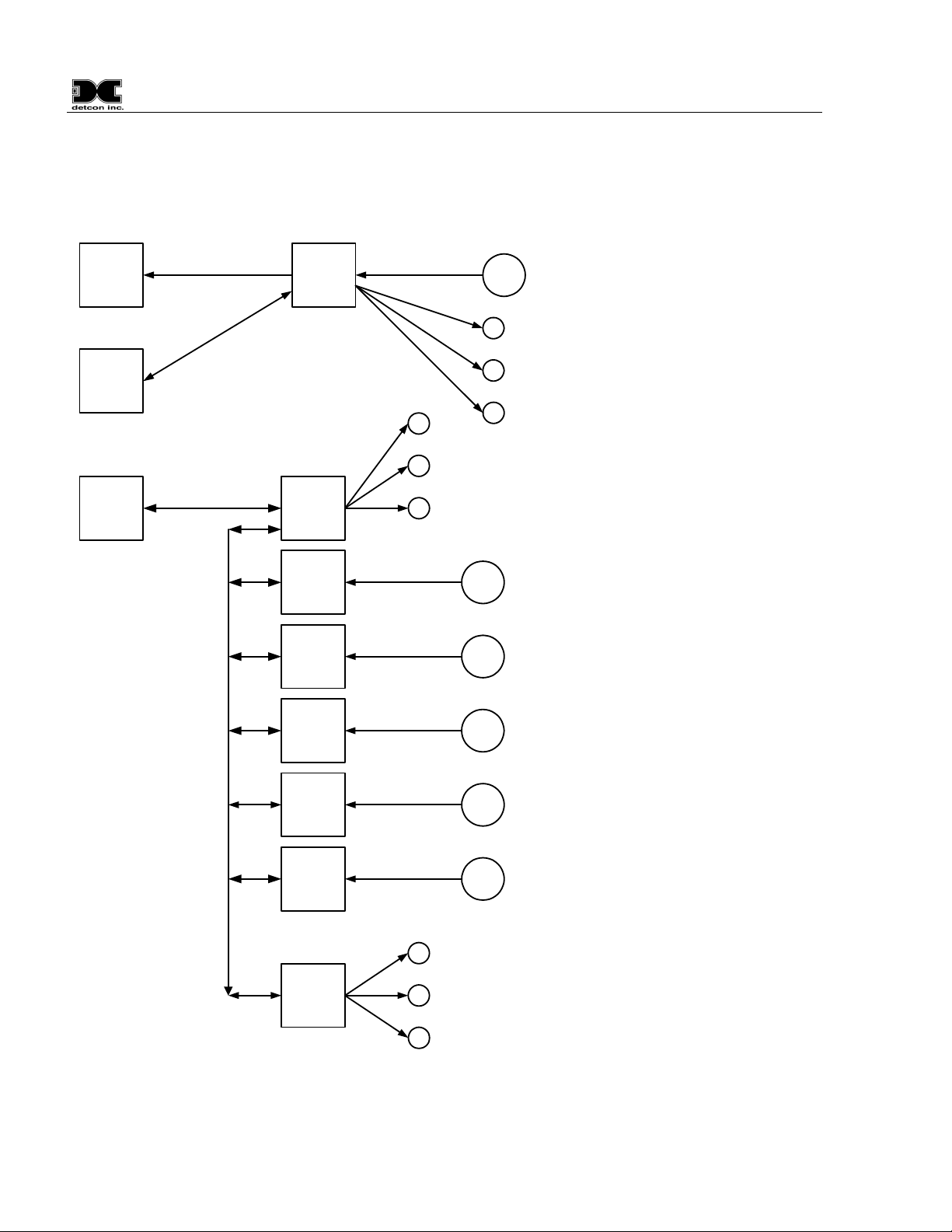
Figure 1 System Application Diagrams
10C Control Module Instruction Manual iv
Page 5

Model 10C
1.0 Description
The Detcon Model 10C single sensor control module (10C Controller) is designed to supervise and display gas
concentration and the status of a remote gas sensor assembly. Mod 10C Controllers may be configured for a
variety of toxic and combustible gases. The 10C Controller is designed to operate on a nominal input voltage
range of 12 VDC to 24VDC and is compatible with a complete line of Detcon enclosures. The available
enclosures include designs for stand-alone, rack, or panel mount indoor non-hazardous areas (NEMA 1 and
12), weatherproof indoor/outdoor locations in non-hazardous areas (NEMA 4 and 4X), and for indoor/outdoor
location in areas classified as Class 1, Division 1, Groups B, C, and D hazardous (NEMA 7).
10C controllers accept 4-20mA current-loop analog input, and feature a four-character display, RS-485
Modbus™ serial communications, 4-20mA analog signal output, and three alarm relays (Alarm 1, Alarm 2,
and Fault). Alarm status is displayed via light emitting diodes (LEDs) located on the front panel. Multiple
10C Controllers, each configured individually and installed in a 10-Series Detcon Enclosure, provide the
monitoring of a variety of gases from several field sensors in one system.
The , exemplifies how 10C Controllers can be utilized and connected
Figure 1 System Application Diagrams
in an overall Model 10C System.
The overall 10C system design includes Facilities Modules and Relay Modules to be applied with a collection
of 10C Controllers. These additional modules are optional and are the same form-factor as the 10C Controller.
The Facilities Module communicates with 10C Controllers to gather data to associate the controllers in
assigned zones, to optionally log data, to report multiple controllers as one Modbus™ ID, and to logically
process and output conditions to the Relay Modules. The scope of this document is restricted to the 10C
controller and does not include any further description of the Facilities and Relay modules.
Pushbuttons located on the Front Panel provide access to retrieve and set information within the controller and
to provide the “Alarm Reset” and “Alarm Silence” functions. The pushbuttons allow the user to navigate
through an interactive menu to access programming of the 10C Controller’s configuration.
RESET ALARM. The “UP”
pushbutton doubles as the Reset
Alarm function.
SILENCE ALARM. The
“DOWN” pushbutton doubles
as the Silence Alarm function.
Figure 2 Front Panel (faceplate) of 10C Controller
10C Control Module Instruction Manual Rev. 0.B Page 1 of 25
Four character display shows
numeric values and text. Scrolls text
for improved interactive function.
Alarm 1 and Alarm 2 LED
indicators.
Fault Alarm LED indicator.
Four pushbuttons provided for
interactive user interface to configure
and view values and settings in
Controller. Keys are: ESCAPE,
ENTER,
×UP and ØDOWN.
Page 6

Model 10C
1.1 Display Function
The main purpose of the 10C Controller’s 4-character display is to show the gas concentration reading at all
times. The reading is given in numeric form and with the desired units, as converted from the current input
signal of the attached gas sensor. Upon operation of the pushbuttons, the display also allows viewing gas type
and units very simply, and with further manipulation allows viewing of any configurable setting.
1.2 Alarm Functions
The alarm configuration, programmed into the controller, determines how the 10C Controller responds to the
4-20mA current-loop analog input. In response to the analog input relative to alarm configuration, the
Controller outputs to its relays and panel LEDs. Alarm configurations for the alarm output relays and LEDs
can be programmed as latching or non-latching, ascending or descending, energized or de-energized, and
silenceable or non-silenceable operation. Any combination of these settings can be programmed to provide
setups for almost any contingency. Some planning may be needed to determine the best configuration for the
application.
1.2.1 Latching or Non-latching Relays
All alarms, Alarm 1, Alarm 2, and Fault, can be programmed as Latching or Non-latching. If an alarm is
programmed to Latch, its corresponding relay and LED Indicator, once activated, will stay activated until
reset, even if the analog input “clears”.
NOTE: The term “Clear” refers to when the alarm condition of the sensor signal returns to
normal, which means that the input current changes to the non-alarm side of the Set-Point
threshold.
If an alarm is programmed as Non-latching, the alarm will not remain activated if the analog input clears.
There is a reset pushbutton on the 10C front panel and there is also a signal input to the 10C controller via the
backplane where an external switch can be connected. When the “Reset” pushbutton on the front panel or the
external switch is momentarily activated, the 10C accepts the signal as an alarm reset function. If resettable
alarms are latched, and in response to the front panel reset switch, the 10C front panel display will scroll the
text: “Reset Alarms?” In response to this query, the “ENT” pushbutton should be pressed to acknowledge the
reset. In response to an front panel reset button acknowledgement , the front panel display scrolls the text:
“Reset DONE”.
The external reset does not have an acknowledge feature and when the 10C Controller senses that the external
reset signal is momentarily activated, the 10C scrolls a text message on its front panel display: “Ext Alm Rst”.
1.2.2 Energized or De-energized Relay Coils
All alarm relays (Alarm 1, Alarm 2, and Fault) can be programmed as normally Energized or normally Deenergized. The standard setting for alarms is De-energized, however, a relay can be programmed as Energized
to provide application specific features. For De-energized relays, the coil will energize in an alarm state. For
Energized relays, the coil is normally Energized and will de-energize in an alarm state. It should be noted that
with a normally Energized relay the N.O. (Normally Open) contact and the COM (Common) contact are
CLOSED, and the N.C. (Normally Closed) contact and the COM contact are OPEN, while in the non-alarm
state.
10C Control Module Instruction Manual Rev.0.B Page 2 of 25
Page 7

Model 10C
A typical application of an Energized relay could be the use of the Fault Relay in a Fail-Safe Fault Circuit. The
loss of functionality of the Controller would cause the coil to De-Energize, thus creating a Fault output to the
receiving equipment, for instance: if power is lost to the 10C Controller, or if the 10C module is unplugged
from the live chassis.
1.2.3 Ascending or Descending
Alarm 1, and Alarm 2 can be programmed for whether the alarm condition is triggered by an increasing
concentration (Ascending) or a decreasing concentration (Descending) through a set-point. The descending
feature, although mainly used for oxygen deficiency, can be useful for setting the trigger of alarms when there
is lack of gas concentration. When set for ascending, the associated alarms will trigger when the gas
concentration goes above the preset set-point. When set for descending, the associated alarms will trigger
when the gas concentration falls below the preset set-point.
1.2.4 Silenceable or Non-silenceable (Alarm Acknowledge)
The terminology “to acknowledge alarms” is synonymous with the terminology “to silence an alarm”. All
Alarms (Alarm 1, Alarm 2, and Fault) can be programmed as Silenceable or Non-silenceable. When an alarm
is programmed as Silenceable, the setting allows the alarm(s) to be silenced even during an alarm state. To
silence an alarm the 10C controller’s alarm must be programmed as Silenceable. When an alarm occurs, the
Silenceable alarm can be silenced by pressing the “SLNC” pushbutton, followed by acknowledging the
“Silence Alarms?” scrolling display by pressing the “ENT” pushbutton. An instance where this feature might
be used is a Strobe device connected to Alarm 1 and a Horn device connected to Alarm 2. In the event of an
alarm, where both the Strobe and Horn were activated, the Horn could be silenced while the Strobe would
remain activated. The silenced state is reset when and if the alarm condition clears and then exceeds alarm setpoint again. The Horn would be reactivated upon the return of the alarm condition.
The “Remote Reset” signal that resets latched alarms also functions as a signal to silence active Silenceable
Alarms.
NOTE: There is a minimum alarm time before acknowledge. When a silenceable alarm
triggers, a minimum-time timer starts. Whenever a silenceable alarm is attempted to be
silenced, the alarm will not silence unless/until the minimum-time timer has timed out. This
guarantees that the alarm has a minimum activity time.
1.2.5 Alarm Reset
An alarm “RESET” pushbutton key-switch is located on the front panel of the 10C Controller. This switch is
used to reset alarms that have been programmed as latching. Once alarm conditions clear, alarms that have
been set as latching can be reset by use of this switch. If cleared latched alarms are pending, pressing the
“RESET” pushbutton will cause the display to scroll the text: “Reset Alarms?” Pressing the “ENT”
pushbutton will reset the alarms which is apparent with the displayed text: “Reset DONE”. The “Remote
Reset” signal, activated from an optional external switch, can be momentarily operated to reset the latched
relays.
The “Remote Reset” signal needs to be operated only once and without an acknowledge sequence, to reset all
pending latched alarms. The text “Ext Alm Rst” scrolls across the 10C Controller front panel display when the
“Remote Reset” signal is sensed.
10C Control Module Instruction Manual Rev. 0.B Page 3 of 25
Page 8

Model 10C
1.3 Fault Circuit Functions
How the 10C Controller responds to a fault condition is determined by the configuration programmed into the
controller. Faults can be programmed as latching or non-latching, energized or de-energized, and silenceable
or non-silenceable operation. Any combination of these settings, and the set-point threshold at which a fault
will trigger, can be programmed to provide setups for almost any contingency. Some system level planning
should be exercised to determine the best configuration for the application.
10C Controllers can be set up in a Fail-Safe Fault supervisory circuit. A Fail-Safe Fault can be created by
setting the Fault Relay as Energized, and connecting the fault circuits of several 10C Controllers in electrical
series. If a fault occurs anywhere in the series circuit, the de-energized fault relay will ‘break’ the circuit,
causing a system fault. The logical “OR” of all faults in the series circuit is simply constructed with such a
method. Mainly, with this set-up, loss of power to any unit will break the circuit because of the normallyenergized coils, thus creating a “Fault Condition” due to the loss of power.
The 10C Controller is designed to detect a sensor as being “In Calibration Mode” when the 4-20mA input is
nominally 2mA. The Display will show “CAL” to signify this sensor Calibration Mode. When the 10C
Controller 4-20mA falls below 2mA, the display will change to “SENS” to signify that there is a sensor related
problem. The Fault Set-Point can be set to any point below 4mA (in steps of .05mA) so that the input of the
sensor can trigger a fault at any point below 4mA.
For 3-wire sensors, the Set-Point can be adjusted to 1.8mA so that when the sensor is in Calibration, a Fault is
not generated. If the input current falls below 1.8mA, a fault will be generated. Since most sensors reduce
their output current for internally detected faults, this set-point is a good setting.
For 2-wire sensors, the sensor uses the loop current for power and so the set-point ordinarily must be set
higher. The fault Set-Point for 2-wire sensors is suggested to be 3.5mA.
10C Control Module Instruction Manual Rev.0.B Page 4 of 25
Page 9

Model 10C
1.4 RS-485 Modbus™
The 10C Controllers feature Modbus™ compatible communications protocol and are addressable via the
programming menu for multi-point communications. Communication is two wire, half-duplex, with the
Model 10C controller set up as a slave device. A master controller can address a maximum of 255 different
10C Controllers. The actual limit of how many 10C Controllers can be connected to one RS485 Multi-drop
line depends upon desired maximum response time, noisy conditions, cable quality, and length. If a multipoint system is utilized, each 10C Controller must be set with a unique Modbus™ address. Address settings
are given in hexadecimal, such as: 01, 02, 03, 04, 05, 06, 07, 08, 09, 0A, 0B, 0C, 0D, 0E, 0F, 10, 11, etc. (See
Section 4.5 to set the Modbus™ address.)
The following register list describes the parameters available from 10C controller:
Register # High Byte Low Byte
40000 Range
40001 Reading
40002 Alarm 1 Set Point
40003 Alarm 2 Set Point
40004 Not Used
40005 Status Bits
40005 Status Bits High Byte:
Bit 15 – Reserved
Bit 14 – Reserved
Bit 13 – Reserved
Bit 12 – Test mode status
Bit 11 – Reserved
Bit 10 – Reserved
Bit 9 – Reserved
Bit 8 – Reserved
40005 Status Bits Low Byte:
Bit 7 – Alarm 2 / 0 – Ascending, 1 – Descending
Bit 6 – Alarm 2 / 0 – Non-latching, 1 – Latching
Bit 5 – Alarm 2 alarm status / 0 – no alarm, 1 – alarm
Bit 4 – Alarm 1 / 0 – Ascending, 1 – Descending
Bit 3 – Alarm 1 / 0 – Non-latching, 1 – Latching
Bit 2 – Alarm 1 alarm status / 0 – no alarm, 1 – alarm
Bit 1 – Fault / 0 – Non-latching, 1 – Latching
Bit 0 – Fault status / 0 – no fault, 1 - fault
1.5 Controller Models
Table 1 provides a list of the available 10C Controller Models, the target gas, the standard Range and Units for
that gas, and the gas formula. Most 10C Controllers can be programmed for a Range other than the standard
Range if needed. (For more information on setting Range, see Section 4.2 Range Set.)
The label on the Model 10 faceplate follows a standard color scheme for identifying the gas type: Yellow =
Solid State H2S, Orange = Combustible Gas, Green = Oxygen and Blue = Electrochemical Toxic (various).
The gas identifier label on the face plate also shows the gas formula and Units: ppm, ppb, or %.
10C Control Module Instruction Manual Rev. 0.B Page 5 of 25
Page 10

Model 10C
Table 1 10C Controller Models
Model # Target Gas Standard Range Formula
AsH3-10 Arsine 0-1 PPM AsH3
Br2-10 Bromine 0-5 PPM Br2
B2H6-10 Diborane 0-5 PPM B2H6
CG–10 Combustible Gases 0-100 % LEL various
CH20-10 Formaldehyde 0-100 PPM CH20
CH30H-10 Methanol 0-100 PPM CH30H
CH3SH-10 Methyl Mercaptan 0-100 PPM CH3SH
CLO2-10 Chlorine Dioxide 0-1 PPM CLO2
CL2-10 Chlorine 0-10 PPM CL2
CO-10 Carbon Monoxide 0-100 PPM CO
COCL2-10 Phosgene 0-1 PPM COCL2
CO2-10 Carbon Dioxide 0-1 % CO2
CS-10 Carbonyl Sulfide 0-100 PPM CS
CS2-10 Carbon Disulfide 0-100 PPM CS2
C2H2-10 Acetylene 0-100 PPM C2H2
C2H3CL-10 Vinyl Chloride 0-100 PPM C2H3CL
C2H30-10 Acetyldehyde 0-100 PPM C2H30
C2H4-10 Ethylene 0-100 PPM C2H4
C2H4O-10 Ethylene Oxide 0-100 PPM C2H4O
C2H5OH-10 Ethanol 0-100 PPM C2H5OH
C2H6S-10 Dimethyl Sulfide 0-100 PPM C2H6S
C3H3N-10 Acrylonitrile 0-100 PPM C3H3N
C3H5OCL-10 Epichlorohydrin 0-10 PPM C3H5OCL
C4H4S-10 Thiophane 0-100 PPM C4H4S
C4H6-10 Butadiene 0-100 PPM C4H6
C4H8S-10 Tetrahydrothiophene 0-100 PPM C4H8S
C4H6O2-10 Vinyl Acetate 0-100 PPM C4H6O2
F2-10 Fluorine 0-1 PPM F2
GeH4-10 Germane 0-2 PPM GeH4
HBr-10 Hydrogen Bromide 0-30 PPM HBr
HCL-10 Hydrogen Chloride 0-30 PPM HCL
HCN-10 Hydrogen Cyanide 0-30 PPM HCN
HF-10 Hydrogen Fluoride 0-10 PPM HF
H2S-100 Hydrogen Sulfide 0-100PPM H2S
H2-10 Hydrogen 0-100 PPM H2
H2-10 LEL Hydrogen 0-100 % H2
NH3-10 Ammonia 0-100 PPM NH3
NO-10 Nitric Oxide 0-100 PPM NO
NO2-10 Nitrogen Dioxide 0-5 PPM NO2
N2H4-10 Hydrazine 0-1 PPM N2H4
O2-10 Oxygen 0-25 % O2
O3-10 Ozone 0-1 PPM O3
PH3-10 Phosphine 0-5 PPM PH3
SiH4-10 Silane 0-50 PPM SiH4
SO2-10 Sulfur Dioxide 0-20 PPM SO2
10C Control Module Instruction Manual Rev.0.B Page 6 of 25
Page 11

Model 10C
2.0 Operator Interface
The 10C Controller is configured by use of the front panel display and pushbuttons. The 10C Controller User
Interface Menu System allows the user to set various parameters associated with the sensor: Gas type, Range,
Units, Alarm settings, and Modbus ID.) Navigation through the menu system is accomplished by use of the
10C Controller’s Front Panel Pushbuttons: the Enter key “ENT”, the Escape key “ESC”, the Up key “×” (or
“RESET”), and the Down key “Ø” (or “SLNC”). The menu system includes the main Programming menu and
submenus as indicated in this section.
2.1 Normal Operation
Normal Operation of the display is to constantly display the Concentration Reading. Upon power-up
initialization of the 10C Controller, the text “WARM UP” is displayed instead of concentration for about sixty
seconds. While in the Normal Operation mode, the Pushbuttons on the left have the meaning “Alarm Reset”
and “Alarm Silence” and are used to Reset and to Acknowledge alarms.
In Normal Operation the Gas Type and Units can be prompted for momentary display by pressing the “ESC”
pushbutton. The Program Configuration Status can be viewed by pressing the “ENT” pushbutton:
View Program Status:
(Lamp Test)
Gas Type
Range
Units
Alarm 1 Set-Point
Alarm 1 Direction
Alarm 1 Latching
Alarm 1 Energized
Alarm 1 Silenceable
Alarm 2 Set-Point
Alarm 2 Direction
Alarm 2 Latching
Alarm 2 Energized
Alarm 2 Silenceable
Fault Set-Point
Fault Direction
Fault Latching
Fault Energized
Fault Silenceable
Modbus™ Address
Firmware Version
Firmware Checksum
Firmware last programmed address (Top of code address in memory)
10C Control Module Instruction Manual Rev. 0.B Page 7 of 25
Page 12

Model 10C
2.2 Program Mode
While in Normal Operation with Concentration displaying, pressing the “ENT” pushbutton and holding it for
about three seconds allows the Program Mode to be accessed. While in the Program Mode, the left
pushbuttons have the meaning “×”and “Ø”which allow moving back and forth or up and down through the
menu and for changing values up and down. If an alarm triggers while in the Program Mode, the 10C
Controller will automatically exit the Program Mode and return to Normal Operation whereupon the up and
down pushbuttons become the alarm reset/silence pushbuttons. The Program Mode allows setting the many
variables in the 10C Controller:
Set Gas Type
Set Range
Set Units
Set Alarm 1:
Set-Point
Direction
Latching
Energized
Silenceable
Set Alarm 2:
Set-Point
Direction
Latching
Energized
Silenceable
Set Fault:
Set-Point Threshold in milliAmps and always descending
Latching
Energized
Silenceable
Set Modbus™ Address
Set Sensor-Cal Mode
Test
Trim Input (Technician Access only)
Trim Output (Technician Access only)
Restore Default Settings (Technician Access only)
10C Control Module Instruction Manual Rev.0.B Page 8 of 25
Page 13

Model 10C
SW1: Access/Normal Switch
JP1: “LPBAK” jumper
(normally open- only
shunt for testing).
Figure 3 Board Assembly Picture of 10C Controller
10C Control Module Instruction Manual Rev. 0.B Page 9 of 25
Page 14

Model 10C
3.0 Normal Operation
3.1 Display Gas Concentration and Alarm Condition
In normal operation, the 10C Controller display continuously shows the sensor’s gas concentration reading
(normally “00”). Pressing the “ENT” pushbutton and holding it down for about three seconds will take the
user into the Program Mode Menu. The “RESET” pushbutton will reset the alarm(s) if the 10C Controller has
been configured properly, and all conditions for Alarm Reset have been satisfied. The “SLNC” Button will
silence the alarm(s) if the 10C Controller has been configured properly, and the alarm silence conditions have
been satisfied.
Table 2, Input Current Below 4mA
Input Current (mA) Display
0-1.8 SENS
1.8-2.4 CAL
2.40-2.56 -9
2.56-2.72 -8
2.72-2.88 -7
2.88-3.04 -6
3.04-3.20 -5
3.20-3.36 -4
3.36-4.00 00
If the current-loop input reads below the Fault Set-Point, the sensor is in Fault. The 10C Controller will
activate the Fault Alarm relay and the Fault LED will activate to indicate the Fault condition.
Current Below 4mA
input measures nominally 2.0mA, the Sensor is in Calibration Mode and the 10C Controller will display the
text ‘CAL’ and the Fault LED will be activated. Very low input current should cause the display to say
‘SENS’ to indicate Sensor Fault. In either case, the Fault Relay will be set, according to the configuration, to
convey a fault status. Note that if the Fault Relay is configured as normally energized, the relay coil will deenergize to convey a fault status. If the Fault Relay is configured as normally de-energized, the relay coil will
energized to convey a fault status.
When an alarm is triggered the corresponding alarm LED will illuminate to indicate the alarm (Alarm 1 and/or
Alarm 2). The corresponding relays will also be set to convey the appropriate status. If the associated alarm
relay is configured as normally energized, the relay coil will de-energize to convey an alarm status. If the
alarm relay is configured as normally de-energized, the relay coil will energize to convey an alarm status.
In normal operation, the 4-20mA current output corresponds directly with the Sensor 4-20mA input. The RS485 Modbus™ serial communications provides the current gas reading and complete fault status when polled
by the Master Controller.
If Program Mode is accessible because of the “ACCESS/NORM” Switch (see location of SW1 in
Board Assembly Picture of 10C Controller
“ENT” key to enter the Program Mode and internal configuration values can be changed. If the
“ACCESS/NORM” Switch (SW1) is in the “NORM” position then only the review of Program Status (see
section 3.2) is accessible.
, reveals what the display should say for input current less than 4mA. If the current-loop
) in the “ACCESS” position, then the user can hold down the
Table 2, Input
Figure 3
10C Control Module Instruction Manual Rev.0.B Page 10 of 25
Page 15

Model 10C
3.2 Displaying Gas Type and Units
While in Normal mode, and while the Gas Concentration is being displayed, the “ESC” button can be pressed
to momentarily display the Gas Type and the Units; for instance: H
S and ppm.
2
3.3 Program Status
While in Normal mode, and while the Gas Concentration is being displayed, the ability to view the
configuration or “Program Status” is always available to all operators. To see the Program Status, the “ENT”
pushbutton should be momentarily pressed and the display will scroll “PR STATUS”. To view the Program
Status press the “ENT” pushbutton again. First the Lamp Test function will light up all display light elements.
Then the 10C Controller display will show the configured settings of each of the configuration parameters
starting with the Gas Type, Range, and Units:
Program Status:
(Lamp Test)
Gas Type
Range
Units
Alarm 1 Set-Point
Alarm 1 Direction
Alarm 1 Latching
Alarm 1 Energized
Alarm 1 Silenceable
Alarm 2 Set-Point
Alarm 2 Direction
Alarm 2 Latching
Alarm 2 Energized
Alarm 2 Silenceable
Fault Set-Point
Fault Direction
Fault Latching
Fault Energized
Fault Silenceable
Modbus™ Address
Firmware Version
Firmware Checksum
Firmware last programmed address (Top of code address in memory)
Only the set value of each item in the list is displayed. The “PR STATUS” first item is Gas Type (for
instance: “LEL” or “H2S” or “CO2”, etcetera) and then display will show Range next (for instance: “100”)
and continue through the list. The user needs to be familiar with the order in which these items are displayed,
the order of which is mostly the same as the programming mode menu list. When all of the items have been
displayed or through use of the “ESC” pushbutton, the 10C Controller returns the display function of Gas
Concentration (see 3.1).
10C Control Module Instruction Manual Rev. 0.B Page 11 of 25
Page 16

Model 10C
4.0 Program Mode
Program Mode is only accessible with the “ACCESS/NORM” Switch (SW1) in the “ACCESS” position.
With the switch in the “NORM” position, only the Program Status Function is available, and only the reading
of configuration values is possible. The “ACCESS/NORM” switch is located in the lower left-hand corner on
the PCA just behind the faceplate, and can be accessed by removing the PCA from the card rack.
Ensure that the “ACCESS”/”NORM” Switch (see location of SW1 in
10C Controller
a few seconds, the 10C Controller will enter the Program Mode Menu. When entering the Program Mode
Menu, the first item on the Program Mode Menu will scroll across the display: “GAS TYPE”. The user can
maneuver through the menu via the “×” (or “RESET”), and the “Ø” (or “SLNC”) pushbuttons. When the
selected menu item is reached, the “ENT” pushbutton is used to enter the selected item. The Program Mode
Menu consists of nine menu selections or functions:
GAS TYPE
RANGE SET
UNITS SET
ALM 1 SET
ALM 2 SET
FAULT SET
MODBUS SET
SENSOR-CAL MODE SET
TEST
Three additional menu selections are available only with “Technician Access”; see 5.0 : Special Configuration
(Technician Access)
TRIM INPUT
TRIM OUTPUT
RESTORE DEFAULTS
NOTE: Pushbutton inactivity during any part of the above procedure will eventually cause the
displayed function to time out and return to the display to Normal Operation with the exception
of Technician tests.
Program Mode Menu is unavailable.
) is in the “ACCESS” position. Upon pressing the “ENT” pushbutton and holding it down for
4.1 Set Gas Type
Figure 3 Board Assembly Picture of
Set Gas Type is used to set the “Gas Type” variable inside the 10C Controller to be agreeable with the sensor
being attached. This setting must match the sensor being attached to the controller. The list of Gas Type
choices can be found in Table 3 List of Gas Types.
The menu item appears as: “GAS TYPE”.
From the “GAS TYPE” display, the “ENT” pushbutton can be used to select a particular gas type. In response
the “ENT” key, the display will start to scroll the current gas type. The gas type will flash while being
displayed to show that the gas type is selectable. The “×” and “Ø” pushbuttons allow movement through the
list of choices of gas types.
10C Control Module Instruction Manual Rev.0.B Page 12 of 25
Page 17

Model 10C
Table 3 List of Gas Types
Gas Type Target Gas Standard Range Formula
H2S Hydrogen Sulfide 0-100PPM H2S
LEL LEL Combustible Gases 0-100 % LEL various
O2 Oxygen 0-25 % O2
CO Carbon Monoxide 0-100 PPM CO
CO2 Carbon Dioxide 0-1 % CO2
Cl2 Chlorine 0-10 PPM CL2
NH3 Ammonia 0-100 PPM NH3
H2 Hydrogen 0-100 PPM H2
NO Nitric Oxide 0-100 PPM NO
NO2 Nitrogen Dioxide 0-5 PPM NO2
SO2 Sulfur Dioxide 0-20 PPM SO2
VOC Volatile Organic Com 0-1000PPM Various
AsH3 Arsine 0-1 PPM AsH3
B2H6 Diborane 0-5 PPM B2H6
C2H2 Acetylene 0-100 PPM C2H2
C2H3O Acetaldehyde 0-100 PPM C2H30
C2H3Cl Vinyl Chloride 0-100 PPM C2H3CL
C2H4 Ethylene 0-100 PPM C2H4
C2H4O Ethylene Oxide 0-100 PPM C2H4O
C2H5OH Ethanol 0-100 PPM C2H5OH
C2H6S Dimethyl Sulfide 0-100 PPM C2H6S
C3H3N Acrylonitrile 0-100 PPM C3H3N
C3H5OCL Epichlorohydrin 0-10 PPM C3H5OCL
C4H4S Thiophane 0-100 PPM C4H4S
C4H6 Butadiene 0-100 PPM C4H6
C4H6O2 Vinyl Acetate 0-100 PPM C4H6O2
C4H8S Tetrahydrothiophene 0-100 PPM C4H8S
CH2O Formaldehyde 0-100 PPM CH20
CH3OH Methanol 0-100 PPM CH30H
CH3SH Methyl Mercaptan 0-100 PPM CH3SH
COCl2 Phosgene 0-1 PPM COCL2
CS2 Carbon Disulfide 0-100 PPM CS2
F2 Fluorine 0-1 PPM F2
GeH4 Germane 0-2 PPM GeH4
HBr Hydrogen Bromide 0-30 PPM HBr
HCl Hydrogen Chloride 0-30 PPM HCL
HCN Hydrogen Cyanide 0-30 PPM HCN
HF Hydrogen Fluoride 0-10 PPM HF
N2H4 Hydrazine 0-1 PPM N2H4
PH3 Phosphine 0-5 PPM PH3
SiH4 Silane 0-50 PPM SiH4
Br2 Bromine 0-5 PPM Br2
CLO2 Chlorine Dioxide 0-1 PPM CLO2
O3 Ozone 0-1 PPM O3
10C Control Module Instruction Manual Rev. 0.B Page 13 of 25
Page 18

Model 10C
NOTE: While the term “LEL” is used here as a Gas Type, it must be understood that the term
stands for Lower Explosive Limit and implies a Range for a combustible gas without being
specific about which explosive gas. If the gas is Methane (CH4), the LEL is about 5% by
volume of Methane in Air. Therefore, 100% LEL is equivalent to about 5% equivalent methane
in air by volume.
When the chosen Gas Type is found, the “ENT” pushbutton can be used to select it. The flashing will stop and
the selected gas type will remain solidly displayed. The “ENT” pushbutton or the “ESC” pushbutton can be
used to leave the gas type selection function and return to the “GAS TYPE” menu item.
Move to another menu item by using the “×” and “Ø” pushbuttons, or use the “ESC” pushbutton to leave
Program Mode and return to Normal Operation of the display.
NOTE: Pushbutton inactivity during any part of the above procedure will eventually cause the
displayed function to time out and return the display to Normal Operation.
4.2 Range Set
“Range Set” is used to set the full-scale range of gas concentration, with respect to the attached sensor type.
This setting must match the attached sensor’s range. Setting the range to something other than the range of
the sensor attached to the controller will cause erroneous readings, and is not advised.
The menu item appears as: “RANGE SET”.
From the “RANGE SET” display the “ENT” pushbutton is used to enter the range set function. The display
will flash the range that is currently set to show that the range is selectable. Use of the “×” and “Ø”
pushbuttons allows movement through the available ranges. When the chosen range value is found, the
“ENT” pushbutton sets the range to the displayed value. The display will stop flashing to signify the range
selection was set. The “ENT” pushbutton or the “ESC” pushbutton can be used to leave the range selection
function and return and return to the “RANGE SET” menu item.
The list of Range selection choices are:
1.00, 2.00, 3.00, 4.00, 5.00, 6.00, 7.00, 8.00. 9.00,
10.0, 11.0, 12.0, 13.0, 14.0, 15.0, 16.0, 17.0, 18.0, 19.0, 20.0, 21.0, 22.0, 23.0, 24.0, 25.0,
30, 35, 40, 45, 50, 55, 60, 65, 70, 75, 80, 85, 90, 95,
100, 150, 200, 250, 300, 350, 400, 450, 500, 550, 600, 650, 700, 750, 800, 850, 900, 950,
1000, 1500, 2000, 2500, 3000, 3500, 4000, 4500,
5000, 5500, 6000, 6500, 7000, 7600, 8000, 8500, 9000, 9500, 9999
NOTE: % (percent) can only be found in the Units selection if the range is set to 100 or less.
Likewise, the range cannot be set above 100 if the Units are set to “%”.
The “×” and “Ø” pushbuttons can be used to move to another menu item, or the “ESC” pushbutton can be
used to leave Program Mode.
NOTE: Pushbutton inactivity during any part of the above procedure will eventually cause the
displayed function to time out and return to the display to Normal Operation..
10C Control Module Instruction Manual Rev.0.B Page 14 of 25
Page 19

Model 10C
4.3 Set Units
Set Units provides a means to adjust the units of measure for the Range selected. The Units should match the
units of measure of the associated sensor.
The menu item appears as: “UNITS SET”.
From the “UNITS SET” display use the “ENT” pushbutton to enter the function. The display will flash the
units of measure currently set. Use the “×” and “Ø” pushbuttons to move through the different units of
measure available. When the correct unit is found, use the “ENT” pushbutton to select that unit of measure.
The display will stop flashing and the units selected will be displayed continuously. Press the “ENT”
pushbutton again, or the “ESC” pushbutton, to leave the function and return to the “UNITS SET” menu item.
Choice for Units is given as:
“ppm” parts per million concentration
“ppb” parts per billion concentration
“%” percent concentration
“mA” milliAmps of loop current
NOTE: % (percent) can only be found in the Units selection if the range is set to 100 or less.
Likewise, the range cannot be set above 100 if the Units are set to “%”.
Move to another menu item by using the “×” and “Ø” pushbuttons, or use the “ESC” pushbutton to leave
Program Mode.
NOTE: Pushbutton inactivity during any part of the above procedure will eventually cause the
displayed function to time out and return the display to Normal Operation.
4.4 Alarm 1, 2, and Fault Set
Alarm 1 Set, Alarm 2 Set, and Fault Set are used to set the configuration parameters that will dictate the
behavior of Alarm 1, Alarm 2, and Fault, respectively. Setting the configuration of Alarm 1, and Alarm 2 is
the same, and setting Fault parameters is mostly the same. The exception is that “FAULT SET” does not
provide an option for “direction” because Fault is always triggered on descending input current, the “direction”
step is skipped when setting up the Fault parameters. The first variable in the list for each function is the SetPoint.
NOTE: For Gas Type “LEL”, the 10C Controller restrains Set-Point settings to be no greater
than 60%, and for Alarm 2 to be not less than Alarm 1 Set-Point and for Alarm 2 to be forced to
Latching relay configuration.
The menu item appears as: “ALARM 1 SET” or “ALARM 2 SET”, or “FAULT SET”, depending upon
which function is chosen.
From the “ALARM 1 SET”, “ALARM 2 SET” or “FAULT SET” display, use the “ENT” pushbutton to
enter the function.
4.4.1 Set-Point
The display will show the current Set-Point. Use the “×” and “Ø” pushbuttons to move through choices of
values for the Set-Point. When the chosen value is found, the “ENT” pushbutton is used to select the value.
10C Control Module Instruction Manual Rev. 0.B Page 15 of 25
Page 20

Model 10C
The display will stop flashing and the selected Set-Point values will be solidly displayed. Pressing the “ENT”
pushbutton again will move to the next parameter in the list.
Note that when setting the Set-Point of the Alarms that the reading is directly proportional to the Range.
Therefore, if the range is set to 500ppm the Set-Point display will step by the increment of 5ppm. That is, for
every press of the “×” or the “Ø” pushbutton, the display will increase or decrease by 5ppm.
When setting the Fault Set-Point, that the reading corresponds directly to milliAmps (mA) units. Input current
that descends through the Fault Set-Point triggers a Fault alarm. For instance, if the desired level for Fault
alarm is when the mA input from a sensor drops below 2.5mA, then this parameter should be set for 2.50.
Latching / Non-latching, Energized / Non-Energized, and Silenceable / Non-silenceable can be set to the
customer’s preference.
4.4.2 Direction: Ascending / Descending
For Fault, the direction is always set to Descending and cannot be changed. For Alarm 1 and Alarm 2 the
flashing display will show the set value of the “direction” variable as “UP” for ascending and “DN for
descending. The “×” and “Ø” pushbuttons can be used to select either “UP” or “DN”. The “ENT”
pushbutton can then be used to accept the value. The display will stop flashing to signify that the value was
set. Pressing the “ENT” pushbutton again will move to the next parameter in the list.
4.4.3 Latching / Non-latching
The flashing display will show the set value of the Latching / Non-latching variable as “LT=0” for NonLatching, and “LT=1” for Latching. The “×” and “Ø” pushbuttons can be used to select either “LT=0” for
Non-latching or “LT=1” for Latching. “ENT” pushbutton can be used to set the selected value, signified by
the fact that display stops flashing. Pressing the “ENT” pushbutton again will move to the next parameter in
the list.
4.4.4 Energized / Non-energized
The alarm relay coil can be set to be energized when the alarm is OFF or non-energized when the alarm is
OFF. The flashing display will show the set value of the Energized / Non-energized variable as “EN=0” for
Non-energized, and “EN=1” for Energized. The “×” and “Ø” pushbuttons can be used to select either
“EN=0” for Non-energized or “EN=1” for Energized. The “ENT” pushbutton can be used to accept the
selected value. The display will stop flashing to signify the value has been set. Pressing the “ENT”
pushbutton again will move to the next parameter in the list.
4.4.5 Acknowledge: Silenceable / Non-silenceable
The flashing display will show the set value of the Silenceable / Non-silenceable Alarm variable as “SL=0” for
Non-silenceable, and “SL=1” for Silenceable. The “×” and “Ø” pushbuttons can be used to select either
“SL=0” for Non-silenceable or “SL=1” for Silenceable. The “ENT” pushbutton can be used to accept the
selected value. The display will stop flashing to signify the value has been set. Pressing the “ENT”
pushbutton again will return to the appropriate “ALARM 1 SET”, “ALARM 2 SET”, or “FAULT SET”
scrolling display.
After setting the alarm/Fault configuration parameters, another Program Mode Menu item can be selected by
use of the “×” and “Ø” pushbuttons, or use of the “ESC” pushbutton to leave Program Mode.
NOTE: Pushbutton inactivity during any part of the above procedure will eventually cause the
displayed function to time out and return to the display to Normal Operation..
10C Control Module Instruction Manual Rev.0.B Page 16 of 25
Page 21

Model 10C
4.5 Modbus™ Set
Set Modbus™ provides a means to set the unique identifying Modbus™ Address. The Address is also known
as the “ID” or “Modbus RTU ID”.
The menu item appears as: “MODBUS SET”.
From the “MODBUS SET” display press the “ENT” pushbutton to enter the function.
To enter “ID Set” function, press the “ENT” pushbutton while the “ID Set” display is scrolling. The display
will flash the current Modbus™ ID Address in Hexadecimal format. Use the “×” and “Ø” pushbuttons to set
the appropriate address and press the “ENT” pushbutton to accept this value. The display will stop flashing
and the ID address will be displayed continuously. Press the “ENT” pushbutton again to leave the menu item.
The display will return to “MODBUS SET”.
The “×” and “Ø” pushbuttons can be used to move to another menu item, or the “ESC” pushbutton can be
used to leave Program Mode.
NOTE: Pushbutton inactivity during any part of the above procedure will eventually cause the
displayed function to time out and return the display to Normal Operation.
4.6 Sensor-Cal Mode
Sensor Cal Mode is used to set the 10C Controller’s output current to 2mA and to inhibit alarm processing
temporarily during a field calibration of the sensor.
The menu item appears as: “SENSOR-CAL MODE”.
From the “SENSOR-CAL MODE” display, the “ENT” pushbutton is used to enter the function. The display will flash and show “Cal-Mode OFF”. The “ENT” pushbutton is used to change the state to “Cal-Mode ON” or the “ESC” pushbutton can be used to escape to the menu.
When the 10C Controller is set to “Cal-Mode ON”, the Current Output will change to and remain at 2mA and
input current will not be processed for alarm triggering. The purpose of this is to allow the sensor’s output
current signal to be ignored while calibrating the sensor.
Until the controller is returned to normal operation by pressing the “ESC” pushbutton or when the 10C
Controller reaches a time limit. To help remind the user that the 10C Controller is in Sensor Calibration Mode,
the Fault LED will flash on/off rapidly and continuously while the display scrolls the text “Cal-Mode ON”.
To escape this function, the “ESC” pushbutton can be pressed and the Sensor-Cal Mode will be turned off and
the 10C Controller will leave the Program Mode and return to Normal Mode.
NOTE: The Sensor-Cal Mode will eventually time-out and return the controller to Normal
Operation if escape of the function is not manually executed. The timeout period is nominally
one hour.
10C Control Module Instruction Manual Rev. 0.B Page 17 of 25
Page 22

Model 10C
4.7 Test
The 10C Controller “TEST” provides a means of checking the external alarm system by artificially setting off Relay Outputs without having to force them on/off through the external sensor input to the Controller. The “TEST” consists of an internal test variable that starts at zero and increases to full-scale range and then decreases back to zero. The internal variable is fed into the internal Controller processing as if it were an external sensor signal. During this test the 10C Output Current stays at nominal zero reading or 4mA. As the internal test variable sweeps through alarm set point values, the appropriate triggering of alarms should occur. This allows the verification of proper operation of the relays, the connection through to the backplane, the wiring, the power source, and the actual Horns, Strobes or other actuated devices. The alarm configuration with regard to set-point thresholds, direction, latching, coil energize setting, and silenceable setting, can all be tested for desired performance. Performance results deviating from expected desired results should be evaluated for cause, whether equipment malfunctions, or incorrect settings or bad configuration.
The “ENT” pushbutton can be used to enter the “TEST” function and “TEST OFF” will display. The “ENT”
pushbutton can be pressed again and the test begins with the displayed text: “TEST ON”. Then the display
will start displaying the internal test variable value, starting at zero and increasing. When the display returns
to zero, the test in complete. The “ESC” pushbutton can be used to return the display to the menu selection or
back to display Normal Operation. The “ESC” pushbutton can be used during the test to exit the test.
NOTE: Alarm Outputs that are latched during the test remain latched after the test is finished
and are not automatically reset.
10C Control Module Instruction Manual Rev.0.B Page 18 of 25
Page 23

Model 10C
5.0 Special Configuration (Technician Access)
Only personnel who are technically trained to configure the equipment should be allowed to access some of
the features built-in to the 10C controller. There are three levels of access:
NORMAL Normal Operation Access (See section 3.0 on “Normal Operation”)
ACCESS Program Mode Access (See section 4.0“Program Mode”)
TECHNICIAN ACCESS Technician Access (This section on Special Configuration)
The “ACCESS/NORM” Switch (see location of SW1 in
) on the 10C Controller controls whether access is limited to just viewing the data and operating the alarm
reset/silence controls, the “Normal” mode, or whether further access is allowed. If it is desired that the 10C
Controller be open to being accessed for changes to configuration data, the “ACCESS” position should be
used, otherwise the switch should be put in the “NORM” position.
Technician access allows further control by personnel of the controller for the purposes of testing some of the
internal workings of the board, for trimming the analog-to-digital conversion and digital-to-analog conversion,
and for restoring the default configuration.
To acquire technician access, only if the switch SW1 is in the ACCESS position, the user can permit
technician access by holding in two front panel switches simultaneously for a continuous duration of at least
ten seconds. By pressing and holding down both the “×” and “Ø” pushbuttons for more than ten seconds, the
technician mode is enabled but not indicated on the display. For a short period of time, the access to
technician functions is available and continue to be available as long as the time is extended by the controller
remaining in the technician access mode. Otherwise, the timer times out and technician mode is not available
until access is gained by the described procedure with holding down the pushbuttons.
5.1 Trim Input
Figure 3 Board Assembly Picture of 10C Controller
Trim Input Mode allows a technician to adjust the analog-to-digital-conversion inside the 10C Controller. A
two-point-trim is accomplished by setting the zero-current input point and the full-scale current input point at
20.0mA. During the input trimming procedure the adjustment at the zero-current input point is called “SET 0
mA” and the adjustment at the 20.0mA current input point is called “SET 20mA”.
NOTE: The Trim Input function is only accessible in Technician Access Mode. The 10C
Controller analog input is trimmed at the factory and under normal circumstances should not
need to be trimmed again.
NOTE: If the Default Settings function (see section 5.3) is executed the input trim values are
restored to un-trimmed values and the 10C Controller’s input will not be as accurate as if it
were trimmed.
In order for the technician to do this procedure, there needs to be available an accurate 20.0mA current source.
The convenient way to accomplish the input trim is to use the Detcon Mod 10/12 Controller Test Fixture.
Another way is to ascertain that the 10C Controller’s output is sufficiently accurate to use as a source of
20.0mA, and temporarily connect a jumper to JP1 “LPBAK” to loop-back the output current to the input
current. An accurate Digital Volt Meter (DVM) can be placed in a current mode and clipped across the JP1
jumper pins to monitor the current. See section 5.2 Trim Output for procedure to trim the output current.
The menu item appears as: “TRIM INPUT”.
10C Control Module Instruction Manual Rev. 0.B Page 19 of 25
Page 24

Model 10C
From the “TRIM INPUT” display the technician can use the “ENT” pushbutton to enter the function. The
display will scroll “SET 0mA”. Apply 0 mA to the 10C Controller’s 4-20mA current input. Removal of the
input current wire to the sensor is the same as applying 0mA. Once 0mA is applied, press the “ENT”
pushbutton to accept the value, the display will scroll “0mA Done”. Press the “ENT” pushbutton again, and
the display will scroll “SET 20mA”. Apply 20.0mA to the current input and press the “ENT” pushbutton.
The display will scroll “20mA Done” if the controller accepts the input. If the controller does not accept the
input, the display will scroll “20mA Failed”. The cause of the failure is that the 10C Controller did not see a
reasonable input current level for 20mA. If this happens the “TRIM INPUT” function did not make an
adjustment to the gain factor for input current. The “ESC” pushbutton must be pushed to leave the function,
and the controller will return to “TRIM INPUT”.
Move to another menu item by using the “×” and “Ø” pushbuttons, or use the “ESC” pushbutton to leave the
“TRIM INPUT” function.
NOTE: This mode does not automatically time-out and must be exited or power-cycled to
return to normal operation.
5.2 Trim Output
Trim Output Mode allows a technician to adjust the 4mA point and the 20mA point of the 10C Controller’s
current output.
NOTE: The Trim Output function is only accessible in Technician Access Mode. The 10C
Controller analog output is trimmed at the factory and under normal circumstances should not
need to be trimmed again.
NOTE: If the Default Settings function (see section 5.3) is executed the output trim values are
restored to un-trimmed values and the 10C Controller’s output will not be as accurate as if it
were trimmed.
The menu item appears as: “TRIM OUTPUT”.
From the “TRIM OUTPUT” display, the technician can use the “ENT” pushbutton to enter the function. The
display will scroll “DAC Trim Out”. Pressing the “ENT” pushbutton will cause the display to change to
“FORCE 4mA”. The mA output of the controller will change to 4mA. The “×” and “Ø” pushbuttons can be
used to make the output current go up or down in small incremental steps. By monitoring the output current,
the technician can adjust the current to exactly 4.00mA. When the output is trimmed to 4.00mA, the
technician can accept the internal trimmed value by pressing “ENT”. When “ENT” pushbutton is pressed, the
zero is trimmed and the display will change to “FORCE 20mA”. The mA output of the controller will change
to 20mA. The “×” and “Ø” pushbuttons can be used to make the output current go up or down in small
incremental steps. When the output is trimmed to 20.0mA, the technician can accept the internal trimmed
value by pressing “ENT”, and if he has pressed “×” or “Ø” at least once, the internal trimmed value will be
accepted. In response to the “ENT” pushbutton, the 10C Controller will return to the display “FORCE 4mA”
allowing multiple passes through this procedure to attain the best trimming. Usually two passes is sufficient.
The “ESC” pushbutton may be pressed at any time to leave the function, and the controller will return to “TRIM OUTPUT”.
Move to another menu item by using the “×” and “Ø” pushbuttons, or use the “ESC” pushbutton to leave the
“TRIM OUTPUT” function.
10C Control Module Instruction Manual Rev.0.B Page 20 of 25
Page 25

Model 10C
NOTE: This mode does not automatically time-out and must be exited or power-cycled to
return to normal operation.
5.3 Default Settings
NOTE: The Default Settings function is only accessible in Technician Access Mode.
Each and any setting within the 10C Controller should be manually changeable to valid values. This feature
sets all configuration values to default state at once, including the trim coefficients. This feature should only
be used as a last resort if it is suspected that 10C Controller function is not correctly functioning due to a bad
configuration.
To utilize this function the “ENT” pushbutton is pressed, in response to which the Display should say “Restore
Defaults?” Another “ENT” pushbutton entry should cause the 10C Controller to load default constants into
the configuration variables and acknowledge with the Displayed text: “Defaults Restored”.
This is a list of configuration values and the default condition restored with this function:
Analog Input Offset (zero) = 0
Analog Input Gain = 1.000
Alarm 1 = Ascending, not latched, not energized, not silenceable
Alarm 2 = Ascending, not latched, not energized, not silenceable
Fault = Descending, not latched, energized, not silenceable
Alarm 1 set point = 10% of range
Alarm 2 set point = 20% of range
Fault set point = 1.80 mA
Gas Type = H2S
Range = 100
Units = ppm
Modbus ID = 01
Analog Output Offset (zero) = 0
Analog Output Gain = 1.000
Baud Rate = 9600
Parity = none
10C Control Module Instruction Manual Rev. 0.B Page 21 of 25
Page 26

Model 10C
6.0 Calibration
The 10C Controller’s conversion, of input current to a displayed value, can be trimmed up or down. Likewise,
the 10C Controller’s output current can be trimmed so that the Master Controller can register what is on the
10C Controller’s display. Each of the 4-20mA analog current input and the 4-20mA analog current output of
the 10C Controller may be trimmed independently. Both are calibrated at the factory and should require no
further adjustments. The independent trim is useful if the Master Controller cannot be itself trimmed and
instead small errors can be adjusted in the 10C Controller’s output current.
NOTE: Calibration of the sensor to standard gas is performed on the sensor itself, not the 10C
Controller. There is no “calibration” of the Controller, only “trim”.
Trim procedures are given in Trim Input, section 5.1, and Trim Output, section 5.2.
NOTE: The 10C Controller analog input and output is trimmed at the factory and under
normal circumstances should not need to be trimmed again.
10C Control Module Instruction Manual Rev.0.B Page 22 of 25
Page 27

Model 10C
7.0 Specifications
Input Power
9 VDC to 28VDC (For use in nominal 12VDC or 24VDC typical systems)
300mA Maximum (Including Sensor)
3W Maximum (Including Sensor)
Operating Temperature
–40°C to +70°C
Humidity: 10 to 95% Non-condensing
Range
Configurable: From 1 to 25 in increments of 1
From 25 to 100 in increments of 5
From 100 to 1000 in increments of 50
From 1000 to 9999 in increments of 500
Accuracy/Repeatability
Sensor input current conversion to 10C Displayed reading: ±1%F.S. after trim procedure
Output current converted from 10C Displayed reading: ±1%F.S. after trim procedure
Inputs/Outputs
Communications: Serial RS-485 Modbus™
Input: Analog 4-20mA DC, current sinking through 100 ohms.
Output: Analog 4-20mA DC, current sourcing.
Open-Collector outputs follow relay coils.
Relays
Relay Contact terminations: Common, Normally Open, and Normally Closed (x 3 Relays)
Relay Contact Manufacturer’s Specification:
Resistive load: 5A, 250VAC; 5A, 30 VDC
Inductive load: 2A, 250VAC; 2A, 30 VDC
Max. Operating current: 5A
Alarm/Fault Alarm Timing and Triggering
Alarms are inhibited during the power-up initialization period indicated by the display “Warm Up”.
Alarm signal delay: nominally 2 seconds
Alarm set-point hysteresis: nominally 1 unit
Alarm minimum activity before acknowledge silences it: 10 seconds.
Warranty
One year
Five year fixed fee service policy
10C Control Module Instruction Manual Rev. 0.B Page 23 of 25
Page 28

Model 10C
8.0 Warranty and Service Policy
Detcon, Inc., as manufacturer, warrants each new Model 10 series digital electronic control module to be free
from defects in material and workmanship under intended normal use for a period of one year from date of
shipment to the original purchaser. Detcon, Inc., additionally provides for a fixed fee repair/replace service
policy which covers Model 10 series digital control modules for a period of five years. The fixed fee service
policy shall affect any necessary factory repair for the period following the one-year warranty period and shall
end five years after expiration of the warranty. The fixed policy rate is $75.00 per control module, per
transaction, during the period of the policy. The policy is FOB Detcon, Inc., The Woodlands, Texas.
10C Control Module Instruction Manual Rev.0.B Page 24 of 25
Page 29

Model 10C
8.1 Revision Log
Revision Date Changes made
0.0 01/13/2009 None Initial release
10C Control Module Instruction Manual Rev. 0.B Page 25 of 25
 Loading...