

Page 1

C-188
P.N. 146230
REVISION L
11/2007
LBB SERIES OVENS
INSTRUCTION MANUAL
LBB Series Despatch Ovens are bench ovens to 204°C (400°F) with forced convection
airflow.
MODEL VOLTS HEATER WATTS AMPS HZ PHASE
LBB1-23A
LBB1-23B
LBB1-43A
LBB1-43B
LBB1-69A 120 2,400 21.6 50/60
LBB1-69B
LBB2-12 240 3,600 16.4 50/60
LBB2-18 240 3,600 16.4 50/60
LBB2-27 240 4,800 21.4 50/60
Prepared by:
Despatch Industries
8860 207th St. West
Lakeville, MN 55044
Customer Service 800-473-7373
120 1,200 11.6 50/60
240 1,200 5.8 50/60
120 1,600 15.0 50/60
240 1,600 7.5 50/60
240 2,400 10.8 50/60
1
1
1
1
1
1
1
1
1
Page 2

NOTICE
CAUTION
Users of this equipment must comply with operating procedures and training of
operation personnel as required by the Occupational Safety and Health Act (OSHA) of
1970, Section 6 and relevant safety standards, as well as other safety rules and
regulations of state and local governments. Refer to the relevant safety standards in
OSHA and National Fire Protection Association (NFPA), section 86 of 1990.
Setup and maintenance of the equipment should be performed by qualified personnel
who are experienced in handling all facets of this type of system. Improper setup and
operation of this equipment could cause an explosion that may result in equipment
damage, personal injury or possible death.
Dear Customer,
Thank you for choosing Despatch Industries. We appreciate the
opportunity to work with you and to meet your heat processing needs. We
believe that you have selected the finest equipment available in the heat
processing industry.
At Despatch, our service does not end after the purchase and delivery of
our equipment. For this reason we have created the Service Products
Division within Despatch. The Service Products Division features our
Response Center for customer service. The Response Center will direct
and track your service call to ensure satisfaction.
Whenever you need service or replacement parts, contact the Response
Center at 1-800-473-7373: FAX 612-781-5353.
Thank you for choosing Despatch.
Sincerely,
Despatch Industries
Page 3
Page 4
Page 5

PREFACE
This manual is your guide to the Despatch oven. It is organized to give you the
information you need quickly and easily.
The INTRODUCTION section provides an overview of the Despatch oven.
The THEORY OF OPERATION section details the function and operation of assemblies
and subassemblies on the Despatch oven.
The INSTRUCTIONS and CONTROL
INSTRUCTIONS sections provide directions on
unpacking, installing, operating, maintaining and
troubleshooting the Despatch oven.
An efficient way to learn about the oven would be to read the manual while working with
the corresponding oven control system. This will give you practical hands-on
experience with information in the manual and the oven.
Before operating the equipment, be sure you
understand all of the technical information contained
in this manual. Information skipped, not understood
or misunderstood could create the possibility of
operating the equipment in an unsafe manner. This
can cause damage to the oven or personnel or reduce
the efficiency of the equipment.
Read the entire
INTRODUCTION and THEORY
OF OPERATION before
installing the oven.
WARNING: Failure to heed
warnings in this instruction
manual and on the oven could
result in personal injury, property
damage or death.
i
Page 6

Revision C: Updated electrical drawings in DRAWINGS AND SPARE PARTS LISTS
section.
Revision D: Corrections.
Revision E: Correction, page 19, set-up parameter table.
Revision F: Parts lists corrections in DRAWINGS AND SPARE PARTS LISTS section.
Revision G: Corrections to SPECIFICATIONS section, addition of options and features
in APPENDIX
Revision H: Change Product Warranty page.
Revision I: Update drawings and hi-limit information.
Revision J: Parts lists corrections in DRAWING AND SPARE PARTS LISTS section.
Corrected Despatch address.
Revision K: Parts lists corrections in DRAWING AND SPARE PARTS LISTS section.
Revision L: Updated warranty
ii
Page 7

Table of Contents
PREFACE........................................................................................................................ i
INTRODUCTION.............................................................................................................1
Special Features..........................................................................................................1
Specifications ..............................................................................................................2
Dimensions ..............................................................................................................2
Power.......................................................................................................................3
Temperature ............................................................................................................4
Capacities ................................................................................................................4
THEORY OF OPERATION ............................................................................................. 5
CONTROL Instrument................................................................................................. 6
HI-LIMIT Instrument.....................................................................................................7
Product HI-LIMIT Instrument....................................................................................8
Oven HI-LIMIT Instrument........................................................................................8
Oven Theory ............................................................................................................9
INSTRUCTIONS ...........................................................................................................10
Unpacking and Inspection .........................................................................................10
Setup.........................................................................................................................11
Operating...................................................................................................................12
Loading the Oven...................................................................................................12
Pre-Startup Checklist.............................................................................................13
Startup ...................................................................................................................14
CONTROL INSTRUCTIONS.........................................................................................16
Changing Setpoint.....................................................................................................16
Parameter Programming Mode .................................................................................17
Operating Parameters............................................................................................17
Operating Parameters............................................................................................18
Set-Up Parameters ................................................................................................19
Changing Display From °C To °F ..................... .........................................................20
Oven Zone Calibration...............................................................................................21
Calibration Instructions...........................................................................................21
HI-LIMIT INSTRUCTIONS.........................................................................................22
Changing Setpoint.....................................................................................................22
Parameter Setup Mode..............................................................................................23
Setup Parameters......................................................................................................24
Changing Display From °C To °F ..............................................................................26
Maintenance ..........................................................................................................27
Checklist ................................................................................................................27
Tests......................................................................................................................28
Replacement Parts.................................................................................................28
Replacement of Control Instrument........................................................................29
Replacement of Hi-limit Instrument ........................................................................30
Replacement of Heater Unit...................................................................................31
Replacement of Fan Motor.....................................................................................32
Troubleshooting.........................................................................................................34
DRAWINGS AND SPARE PARTS LISTS.....................................................................36
LBB1-23A-1 Parts..................................................................................................37
LBB1-23A-1 Drawing .............................................................................................38
iii
Page 8

LBB1-23B-1 Parts..................................................................................................39
LBB1-23B-1 Drawing .............................................................................................40
LBB1-43A-1 Parts..................................................................................................41
LBB1-43A-1 Drawing .............................................................................................42
LBB1-43B-1 Parts..................................................................................................43
LBB1-43B-1 DRAWING .........................................................................................44
LBB1-69A-1 Parts..................................................................................................45
LBB1-69A-1 Drawing .............................................................................................46
LBB1-69B-1 Parts..................................................................................................47
LBB1-69B-1 Drawing .............................................................................................48
LBB2-12-1 Parts.....................................................................................................49
LBB2-12-1 Drawing................................................................................................50
LBB2-18-1 Parts.....................................................................................................51
LBB2-18-1 Drawing................................................................................................52
LBB2-27-1 Parts.....................................................................................................53
LBB2-27-1 Drawing................................................................................................54
DESPATCH CUSTOMER SERVICE.............................................................................55
Procedures and Customer Responsibilities...............................................................55
Attachment A - Sustained Service Support............................................................56
APPENDIX: OPTIONAL FEATURES............................................................................57
Protocol Plus Control Option .....................................................................................57
Timer Option..............................................................................................................57
Timer Operation.....................................................................................................58
Timer Configuration................................................................................................58
Stand Assembly Instructions .....................................................................................59
Stacking Kit Assembly Instructions............................................................................60
Timer Option with Audible and Visual Alarm..............................................................61
High Limit Alarm Option.............................................................................................61
Recorder Option ........................................................................................................62
iv
Page 9

INTRODUCTION
The INTRODUCTION section provides an overview of the Despatch LBB Series
Ovens. The LBB Series Ovens have the most effective heat distribution and the
fastest processing time of any lab oven its size. Air is discharged through ducts
on both sides of the oven distributed through the chamber, and returned through
the heater cover.
Special Features
The sturdy construction and high grade insulation of the Despatch LBB Series
ovens contribute to excellent high temperature performance. Other special
features include:
• Proportional digital CONTROL instrument to control temperature
fluctuations.
• Manual reset HI-LIMIT instrument to protect the chamber workload as well
as the oven itself.
• Unique Despatch design to combine forced circulated air through side ducts
for the ultimate in temperature performance.
• Welded double wall construction and fiberglass insulation to reduce heat
loss. Silicone rubber gaskets further minimize heat leakage.
• Rapid response heater with a five year warranty.
• Scratch-resistant baked enamel exterior and stainless steel interior for easy
cleaning.
• Space-saving, stackable design.
• Optional control panel located on the bottom of the oven.
1
Page 10
Specifications
Dimensions
Model
LBB1-23
LBB1-43
LBB1-69
LBB2-12
LBB2-18
LBB2-27
Chamber Size
in (cm)
W D H
18
18
(46)
(46)
(30)
24
14
(61)
(36)
(56)
30
18
(76)
(46)
(56)
30
20
(76)
(51)
(89)
37
24
(94)
(61)
(89)
37
37
(94)
(94)
(89)
12
22
22
35
35
35
Capacity
feet3
(liters)
2.3
(65)
4.3
(122)
6.9
(195)
12.1
(343)
18
(510)
27.7
(785)
Overall Size
in (cm)
W
24
(61)
30
(76)
34
(86)
36
(91)
43
(102)
43
(102)
D
23
(58)
19
(48)
23
(58)
25
(64)
29
(74)
42
(107)
H
26
(66)
36
(91)
36
(91)
51
(130)
51
(130)
51
(130)
Shelves
Provided on
Shelf Centers
2 on 2"
2 on 2"
2 on 2"
2 on 2"
2 on 2"
2 on 2"
Maximum
Number of Shelf
Positions
5
10
10
16
16
16
Chamber
Doors
1
1
2
2
2
2
2
Page 11

Power
Line voltages may vary in some geographical locations. If your line voltage is
much lower than the oven voltage rating, warm up time will be longer and motors
may overload or run hot. If your line voltage is higher than nameplate rating, the
motor may run hot and draw excessive amps.
If the line voltage varies more than 10% from the oven voltage rating, some
electrical components such as relays, temperature controls, etc. may operate
erratically.
Model Volts
LBB1-23A
LBB1-23B
LBB1-43A
LBB1-43B
LBB1-69A
LBB1-69B
LBB2-12
LBB2-18
LBB2-27
120
240*
120
240*
120
240*
240
240
240
Amps
11.6
5.8
15.0
7.5
21.6
10.8
16.4
16.4
21.4
Hertz
50/60
50/60
50/60
50/60
50/60
50/60
50/60
50/60
50/60
Phase
1
1
1
1
1
1
1
1
1
Heater (KW)
1.2
1.2
1.6
1.6
2.4
2.4
3.6
3.6
4.8
Cord and Plug
Included, 15 Amp
Included, 15 Amp
Included, 20 Amp
Included, 15 Amp
None, Hardwired
None, Hardwired
None, Hardwired
None, Hardwired
None, Hardwired
• The LBB1-69, LBB2-12, LBB2-18 and LBB2-27 must be hardwired to the electric supply
using 10AWG or larger wires suitable for at least 75°C (167°F).
• Ovens designed for 240 volts (see name plate on oven) will operate satisfactorily on a
minimum of 208 volts, but with a 25% reduction in heater power. If your power
characteristics are lower, contact Despatch Industries.
3
Page 12
Temperature
LBB
Model
Time to Temperature 40°C - 150°C
(approximate minutes
with no load) 40°C - 204°C
Recovery Time 150°C
Door Open 1 Min. (approx.
minutes with no load) 204°C
Temperature Uniformity 150°C
At:
204°C
Operating Range
w/20°C Ambient
Control Stability +/- 0.5°C
1-23
3°C
4°C
17
30
2
4
+/-
+/-
1-43
17
30
2
4
+/3°C
+/-
4°C
35°C - 204°C 40°C - 204°C
1-69
15
26
3
6
+/- 3°C
+/- 4°C
2-12
15
30
3
6
+/- 2°C
+/- 3°C
2-18
17
33
3
7
+/- 3°C
+/- 4°C
2-27
+/- 3°C
+/- 4°C
17
33
4
8
* Dampers must be open to operate at the minimum temperature.
NOTE: Time to Temperature and Temperature Uniformity values are based on
240V/60 Hz operation, with control panel located on top. Actual results may vary
slightly depending on unit configuration and operating conditions.
Capacities
LBB
Model
Maximum load capacity (lbs)
Maximum shelf load (lbs) 50 50 200 * 200 * 200 * 200 *
Exhaust Capacity, CFM 1 2 3 12 14 14
1-23
200 200 400 600 600 600
1-43 1-69
2-12
2-18
NOTE: Maximum load capacity not valid with “control panel located on bottom”
option.
• LBB1-69 and larger models have reinforced shelves. Standard duty (50
pounds max) shelves are also available.
WARNING: Do not exceed a total of 400 pounds for stacked LBB1-69.
2-27
4
Page 13
THEORY OF OPERATION
The THEORY OF OPERATION section details the function and operation of
assemblies and subassemblies on the Despatch LBB Series Ovens.
The Despatch LBB Series Ovens have the most effective heat distribution system
and the fastest processing time of any lab oven its class. These ovens are
especially useful for testing, preheating, sterilizing, drying, aging and curing as well
as other production applications.
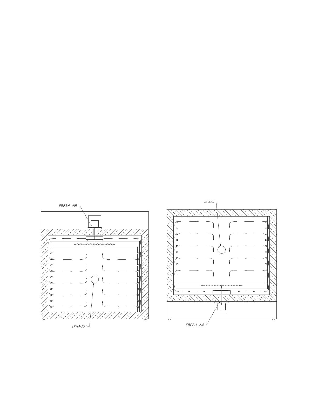
The Despatch LBB Series Ovens incorporate forced circulating airflow with
precision digital control to deliver fast processing. The overall result is efficient
productivity under strenuous conditions.
The LBB Series Ovens are precise and practical. The unique Despatch design
moves convected heat through stainless steel ducts on each side. The air is
circulated with a high volume fan. The Despatch LBB Series Ovens employ higher
volume fans than any competitive model. The chamber can be densely loaded
without interfering with the process. For your convenience the fresh air intake is
fixed. The exhaust rate is regulated by a damper on the back of the unit.
Forced Circulating Airflow in Despatch LBB Ovens
5
Page 14
CONTROL Instrument
or
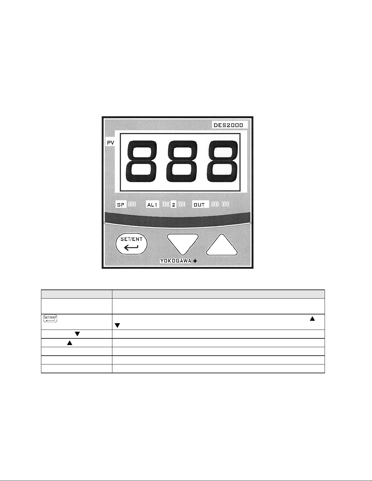
The oven is equipped with a microprocessor based digital control instrument. The
Despatch CONTROL instrument has been configured as a proportional controller
and set to its optimum operating values. Initially the CONTROL will allow the
heater to operate at full power. However, as the actual oven temperature reaches
the setpoint, the Proportional Control will cycle the heater on and off, minimizing
process temperature fluctuations.
CONTROL Instrument
Features Description
Main (PV) Display Displays the actual oven temperature or displays the setpoint when the set
key is pressed. Displays parameter code and value.
Key
Down Key Decreases a setpoint or mode parameter.
Up Key Increases a setpoint or mode parameter.
LED SP Indicator Lights when the setpoint value is displayed.
LED OUT Indicator Lights when the control is calling for heat.
LED AL1 –2 Indicator N/A
Switches between PV and SP displays. Enters the data changed by the
keys. Switches through parameter displays.
6
Page 15
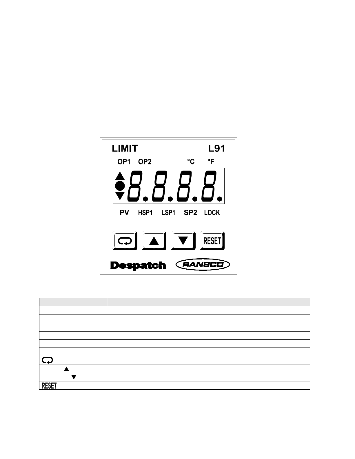
HI-LIMIT Instrument
The oven is equipped with a HI-LIMIT instrument. The purpose of the HI-LIMIT
instrument is to provide a protective measure for the product and/or the oven itself.
If the setting on the HI-LIMIT is exceeded, the heating process will discontinue,
thus protecting the product and/or the oven.
Set the HI-LIMIT instrument to a temperature 10°C - 14°C higher than the
CONTROL instrument setpoint or a temperature that should not be exceeded in
the process. If the setting on the HI-LIMIT instrument is exceeded the heater will
shut down. The HI-LIMIT instrument must be manually reset by pushing the
RESET button on the HI-LIMIT instrument.
HI-LIMIT Instrument
Features Description
OP1 Output 1 status value. (OP2 normally not used for LBB Ovens).
°C/°F
PV Process value.
HSP1 High limit setpoint 1. (LSP1 normally not used for LBB Ovens).
SP2 Setpoint 2 for output 2 (normally not used for LBB Ovens).
LOCK Lock status indicator.
Up Key Increases a setpoint or mode parameter.
Down Key Decreases a setpoint or mode parameter.
Degree indicator.
Scroll Key, used for advancing available displays.
Reset the high limit, return to normal display.
7
Page 16

Product HI-LIMIT Instrument
If the product being processed has a critical high temperature limit, the HI-LIMIT
instrument should be used as a product HI-LIMIT instrument. The HI-LIMIT
instrument should be set to a temperature somewhat below the temperature at
which the product could be damaged.
Oven HI-LIMIT Instrument
If the product does not have a critical high temperature limit, the HI-LIMIT can be
used as an oven HI-LIMIT instrument. An oven HI-LIMIT instrument protects oven
equipment. The HI-LIMIT should be set at 204°C
8
Page 17

Oven Theory
The oven has an efficient forced circulating oven to 204°C (400°F). A forced
circulating oven relies on a circulating motor to move air through the chamber ,
which is much more efficient and uniform than a gravity convected oven. In
addition, it takes a finite amount of time for the oven to soak in at the desired
setpoint. The time that it takes the unit to soak in at setpoint is related to such
parameters as chamber area, load mass and the ability to absorb heat and
exhaust rate. The unique Despatch design and CONTROL action compensates
for these facts.
The oven uses an indicating microprocessor based digital control that displays the
actual chamber temperature at the sensing point. Despatch strategically locates
the CONTROL's temperature sensor to optimize the control action for the entire
chamber for various load conditions. The CONTROL display may fluctuate a few
degrees around the setpoint, but the overall chamber temperature will remain very
stable. The underlying reason for this is that the display is showing temperature
fluctuations at the temperature sensor location, not the overall chamber
temperature. The strategic location of the sensor compensates for delays in heat
convection and enhances the performance and temperature control of the oven.
The oven has been engineered to have an overall result of quality productivity
where fast processing and versatility are critical.
9
Page 18

INSTRUCTIONS
The INSTRUCTIONS section provides directions on unpacking, installation,
operation and maintenance of the Despatch LBB Series Ovens.
Unpacking and Inspection
Remove all packing materials and thoroughly inspect the oven for damage of any
kind that could have occurred during shipment.
• See whether the carton and plastic cover sheet inside carton are still in
good condition.
• Look at all outside surfaces and corners of the oven for scratches and
dents.
• Check the oven controls and indicators for normal movement, bent shafts,
cracks, chips or missing parts such as knobs and lenses.
• Check the door and latch for smooth operation.
If there is damage, and it could have happened during shipment follow these
instructions.
1. Contact the shipper immediately and file a written damage claim, before
contacting Despatch Industries.
2. Contact Despatch Industries to report your findings and to order
replacement parts for those that were damaged or missing.
3. Please send a copy of your filed damage claims to Despatch.
Next, check to make sure you have received all the required materials. Your
shipment should include:
• One (1) Despatch oven,
• One (1) Instruction manual,
• One (1) Warranty card,
• Two (2) Shelves
• One (1) Damper assembly
If any of these items are missing from the packaged contents, contact Despatch
Industries to have the appropriate materials forwarded to you.
10
Page 19

Setup
1. Place oven on a bench top or an optional stand.
The oven must have a minimum of two (2) inches clearance in the rear to
provide proper ventilation. The oven may be placed next to another
cabinet, or next to another oven, with three (3) inch clearance (the doors will
still open).
Make sure oven is level and plumb; this will
assure proper heat distribution and operation of
all mechanical components.
2. Identify correct power source indicated on the
specification plate.
3. Hardwire oven directly to the electric supply.
WARNING: All grounding
and safety equipment must
be in compliance with
applicable codes, ordinances
and accepted safe practices.
11
Page 20

Operating
Users and operators of this oven must comply
with operating procedures and training of
operating personnel as required by the
Occupational Safety and Health Act (OSHA)
of 1970, Section 5 and relevant safety
standards, and other safety rules and
regulations of state and local governments. Refer to the relevant OSHA and
National Fire Protection Association (NFPA) safety standards.
WARNING: Do not use oven in
wet, corrosive or explosive
atmospheres unless this oven is
specifically designed for a special
atmosphere.
Loading the Oven
Despatch Industries cannot be responsible for either the
process or process temperature used, or for the quality of
the product being processed. It is the responsibility of the
purchaser and operator to see that the product
undergoing processing in a Despatch oven is adequately
protected from damage.
Carefully following the instructions in this manual will help
the purchaser and operator in fulfilling that responsibility.
The two shelves are designed to be pulled out about half way without tipping. The
support capacity of the shelves is listed in the Capacities Table in the
Specifications section in this manual. Do not overload the shelves.
Distribute the workload evenly so that airflow is not restricted. Do not overfill your
oven. The workload should not take up more than two-thirds of any dimension of
the inside cavity.
WARNING: Never
operate oven at a
temperature in excess
of the maximum
operating temperature
of 204°C (400°F).
12
Page 21

Pre-Startup Checklist
Know the system. Read this manual carefully. Make use of its instructions
and explanations. The know how of safe, continuous, satisfactory, troublefree operation depends primarily on the degree of your understanding of the
system and of your willingness to keep all parts in proper operating
condition.
Check line voltage. Voltage must correspond to nameplate requirements of
motors and controls. Refer to the section on power connections in the
INTRODUCTION of this manual.
Fresh air, exhaust, and electrical cabinet openings.
Do not be careless about restrictions in and around
the fresh air and exhaust openings. Under no
condition permit them to become so filled with dirt
that they appreciably reduce the air quantity. Refer
to the Set-up instructions in this manual.
Ventilation. There is an exhaust opening in the
rear of the unit.
The exhaust vent may have to be closed to reach the maximum temperature of
204°C, especially if operating on 208 volts. They may need to be opened to
operate properly at the lower range of the oven's design
Helpful hints
• For drying ovens, open vent to prevent buildup of moisture.
• For sample heating, close the vent when no ventilation is required.
NOTE:
The exhaust vent may
have to be adjusted to
achieve maximum
performance at various
operating temperatures.
13
Page 22

Startup
For fastest oven heat-up time, close the
exhaust vent. After the desired temperature is
reached, the vent may be adjusted as needed.
1. Start oven.
a. Turn POWER switch to on. The circulating fan will start.
b. Set exhaust vent to desired opening. The vent may have to be adjusted
to achieve maximum performance at various operating temperatures.
WARNING: Do not use
flammable solvent or flammable
material in this oven. Do not
process closed containers of any
substance or liquid in this oven
because they may explode under
heat.
LBB Control Panel
2. Enter setpoint on the HI-LIMIT instrument.
Set HI-LIMIT instrument to a temperature
10°C to 14°C higher than the setpoint or to a
temperature that should not be exceeded in
the process.
a. If the
and hold the
seconds to enable the and keys.
b. Press
c. Use key and key to set hi limit temperature.
d. Press
process variable PV mode.
3. Enter setpoint on the CONTROL instrument.
a. Press key until the SP LED is lit.
b. Use key and key to set operating temperature.
c. Press key to enter setpoint.
on the HI-LIMIT is lit, press
key, HSP1 will be lit.
or
for four (4)
once to return (also enters the value) to the
14
NOTE:
If the HI-LIMIT instrument is
exceeded the heater will shut
down. Reset the HI-LIMIT by
pushing
instrument.
on the HI-LIMIT
Page 23

d. Press key again to display process temperature.
4. Turn HEATER switch to the on position. When process value on the
CONTROL reaches setpoint, the OUT LED will cycle on and off to maintain
the temperature setpoint. The OUT LED will be lit when the control is
calling for heat.
5. Turn the HEATER switch off after heating cycle is complete. Do not turn the
fan off until the oven chamber temperature is below 100°C (212°F).
15
Page 24

CONTROL INSTRUCTIONS
The oven has been tested and control preset at the factory
for normal operating conditions. In most applications, it will
not be necessary to alter the oven's settings, except for the
Setpoint. This section contains information and reference
material to change Setpoint, display from °C to °F, and
access the Operating and Set-up modes. This section also
covers oven zone calibration for the CONTROL.
The CONTROL instrument was carefully programmed at the factory using the
Operating and Set-up modes. The parameters that may be accessed include
tuning and display functions, and thermocouple selection.
The Oven Zone Calibration section covers the procedure necessary to recalibrate
the CONTROL. Recalibration may be necessary to align the CONTROL for a
specific operating condition.
WARNING: Failure to
heed warnings in this
manual and on the
oven could result in
death, personal injury
or property damage.
Changing Setpoint
To enter Setpoint on the CONTROL instrument:
1. Press key. The SP LED will be lit.
2. Use key or key to set operating
temperature. The right decimal point LED will
flash indicating that the Setpoint is being
changed. This will stop flashing when the new
value has been entered.
3. Press key to enter Setpoint.
4. Press key again to display process temperature.
WARNING: Never
operate oven at a
temperature in excess
of the maximum
operating temperature
of 204°C (400°F).
16
Page 25

Parameter Programming Mode
The control parameters are set through the
Operating and Set-up modes. In most applications, it
is not necessary to alter the oven settings. The
following instructions describe how to access, view
and, if desired, change the parameters.
Once the Operating and Set-up modes are
accessed, the SP LED will start blinking on and off.
The CONTROL will not allow the display to be altered improperly.
The CONTROL will automatically exit the Parameter Programming mode if no keys
are pressed for about 2 minutes.
1. Press key for three (3) seconds.
2. Press the key until the desired parameter is displayed. See Operating
and Setup Parameter Tables on the following pages.
3. Press the or to display value.
4. Use the or to move to the desired setting.
5. Press the key to enter the value.
6. Press and hold the key for three (3)
seconds to return to the display mode.
WARNING: Make sure you
understand what you are
changing before doing so.
Changing the program
parameters will alter the
functions of the CONTROL.
CONTROL Instrument
17
Page 26

Operating Parameters
Code
CtL
At
P
I
d
nr
HyS
Ct
FL
bS
LoC
*If P is not displayed the Control Mode (CtL) must be first set to PID.
CtL Control Mode - This parameter determines whether controller functions as a
At Auto-tuning – OFF for PID tuning, ON for controller to tune process.
P Proportional Band - Expressed in degrees. This value determines the band
I Integral Time - Expressed in seconds. This parameter corrects for errors in
D Derivative Time - Expressed in seconds. This effect of the derivative time is
nr Manual Reset - Expressed in percent. Controller outputs this value when
HyS Hysteresis - Expressed in degrees. When CtL = OFF, this value
Ct Cycle Time - Expressed in seconds. This is the total time for one ON/OFF
FL Input Filter – Expressed in seconds. This function should be used when the
Name
Control Mode
Auto-tuning
Proportional Band
Integral Time
Derivative Time
Manual Reset (only when I & d are OFF)
Hysteresis (only when CtL is ONF, change CtL to PID) N/A
Cycle Time
Input Filter
PV Bias (Offset)
Key Lock
Settings
PID
OFF
4 (8 if °°°°F)*
15
0
N/A
1
0
0
1
time proportional or an on/off control.
width on both sides of the setpoint within which the control provides
proportional control.
actual temperature versus the setpoint.
in direct proportion to the time setting.
process variable equals setpoint (Only if I = 0).
determines the change in temperature needed to turn controller output from
full off to full on.
cycle of the controller output during the proportional action.
PV may fluctuate greatly (i.e. input signal contains noise).
18
Page 27

= Prevents changing of all parameters except setpoint.
bS PV Bias - Expressed in degrees, from –199 to 999. This parameter used to
set the actual oven temperature to the controller display.
LoC Key Lock - This provides levels of access to the controller.
0 = No key lock, full access to controller.
1
2 = Prevents all parameters from being changed including the setpoint.
–1 = Set to enter the Setup parameter setting display.
The controller is set to LoC=1 at the factory. This prevents inadvertent changing
of control parameters with the exception of setpoint.
If it becomes necessary to alter control parameters, change the LoC=1 to LoC=0.
Follow the parameter programming mode found earlier in this manual.
When LoC = -1, the parameters are displayed in the order shown in the Set-Up
Parameters section, below. Note: If you are unable to change the setup
parameters, go back out and change the LoC = 0. Press the
appears again, change LoC = -1 and press the
key.
key until LoC
Set-Up Parameters
Code
In Input Type
SPH
SPL Setpoint Low
dr Direct/Reverse Action
dSP PV/SP Display
Setpoint High
Name
Settings
5 (35 if °°°°F)
204 (400 if °°°°F)
0 (32 if °°°°F)
0
0
In Input Type – This parameter is set for type of input and whether PV is in °C
or °F.
SPH The maximum setpoint limit for oven. The user cannot set the setpoint
above the maximum setpoint.
SPL The minimum setpoint limit of oven. The user cannot change the setpoint
below this lower setpoint limit.
dr Direct/Reverse action. This value is set for 0 (reverse action).
dSP Priority of PV/SP display. This parameter either displays the PV (process
variable) or SP (setpoint). 0 = process variable, and 1 = setpoint.
19
Page 28

Changing Display From °C To °F
CONTROL.
The control can be configured for either °C or °F. Use the following steps to
change control from displaying °C to °F.
1. Press and hold the for three (3) seconds.
2. The display will read CtL. The SP LED will
flash indicating that Operating Parameter
mode has been entered.
3. Press the until LoC appears on the
display. Press the or to enter the
parameter.
4. Press the to set the value to –1. The SP LED will flash rapidly, indicating
that the Set-Up Parameter mode has been entered.
5. Press the to enter the value. The display will read In. Press the or
to enter the parameter. Note: If you are unable to change the setup
parameters, go back out and change the LoC = 0. Press the
LoC appears again, change LoC = -1 and press the
6. Enter a value of 35. The right decimal point LED will flash indicating that
the setpoint is being changed. This will stop flashing when the new value
has been entered.
7. Press the to enter the value.
8. Press the until SPH is displayed. Press
the or to enter the parameter.
9. Enter a value of 400.
10. Press the to enter the value.
11. Repeat steps 12 –14 for SPL; the value is 32.
12. Press and hold the for three (3) seconds to return to the operation
mode. The control now reads °F. Enter the desired setpoint.
13. Refer to Parameter Programming Mode, Operating Parameters section to
change tuning parameters, if necessary.
WARNING: Make sure
you understand what
you are changing
before doing so.
Changing the program
parameters will alter the
functions of the
key until
key.
NOTE: To change from
°F to °C repeat the above
steps. The following are
the values to be entered:
In = 5
SPH = 204
SPL = 0
20
Page 29

Oven Zone Calibration
CONTROL.
The CONTROL instrument has been tested and calibrated at the factory. Under
normal operating conditions, recalibration should not be necessary. However, if
the user would like to recalibrate the CONTROL for a specific operating condition,
then recalibration is easily accomplished.
Calibration Instructions
(Equipment needed: Temperature Measuring Device with a Compatible
Temperature Sensor)
1. Verify that the bS (PV Bias) programmed in the
CONTROL is 0. Refer to Instructions on viewing
the parameter in the PARAMETER
PROGRAMMING mode.
2. Locate the temperature sensor of the temperature
measuring device at the center of the chamber.
3. Operate the oven until it reaches the desired
operating temperature and the CONTROL is regulating. The user may wish
to have a loaded chamber with a standard amount of product to simulate a
specific operating condition. It will take several minutes for the unit to
stabilize at the controlled temperature. Allow at least 30 minutes of
operation at the stabilized temperature before proceeding.
4. Subtract the average controlled temperature (number appearing on the
CONTROL display) from the actual oven temperature (number appearing
on the temperature measuring device display). The CONTROL and the
device must be in the same scale (°C or °F).
Actual Oven Temperature - Controlled Temperature = calculated value
5. Enter the calculated value from Step 4 as the new bS (PV Bias) value in the
instrument.
WARNING: Make sure
you understand what
you are changing
before doing so.
Changing the program
parameters will alter the
functions of the
21
Page 30

HI-LIMIT INSTRUCTIONS
The oven has been tested and the HI-LIMIT preset at
the factory for normal operating conditions. In most
applications, it will not be necessary to alter the oven's
settings, except for the Setpoint. This section contains
information and reference material to change Setpoint,
access the Set-up mode and change display between
°C and °F.
The HI-LIMIT instrument was carefully programmed at the factory using the
Operating and Set-up mode. The parameters that may be accessed include;
display functions, and thermocouple selection.
WARNING: Failure to
heed warnings in this
manual and on the
oven could result in
death, personal injury
or property damage.
Changing Setpoint
Enter setpoint on the HI-LIMIT instrument. Set HILIMIT instrument to a temperature 10°C to 14°C
higher than the setpoint or to a temperature that
should not be exceeded in the process.
1. If the
hold the
the and keys.
2. Press
3. Use key and key to set hi limit temperature.
4. Press
variable PV mode.
5. If the HI-LIMIT instrument is exceeded the heater will shut down. Reset the
HI-LIMIT by pushing on the HI-LIMIT instrument.
on the HI-LIMIT is lit, press and
for four (4) seconds to enable
key, HSP1 will be lit.
or
once to return (also enters the value) to the process
WARNING: Never operate
oven at a temperature in
excess of the maximum
operating temperature of 204°C
(400°F).
22
Page 31

Parameter Setup Mode
functions of the HI
-
LIMIT.
The HI-LIMIT parameters are set through the
Operating and Set-up modes. In most applications, it
is not necessary to alter the oven settings. The
following instructions describe how to access, view
and, if desired, change the parameters.
If the on the HI-LIMIT is lit, press and hold the
enable the and keys. The HI-LIMIT will automatically exit the Setup mode if
no keys are pressed for about two (2) minutes.
1. Press and hold the
been entered.
2. Press the
displayed. See the Setup Parameter Table on the
following page.
3. The display will alternate between the parameter
name and value.
4. Use the or to move to the desired setting.
5. Press the key, this enters the value and
advances to the next parameter.
6. To get out of the setup parameters press the
automatically exit the Setup mode if no keys are pressed for about two (2)
minutes.
key until the desired parameter is
key for four (4) seconds, the setup mode has now
WARNING: Make sure you
understand what you are
changing before doing so.
Changing the setup
parameters will alter the
key for four (4) seconds to
HI-LIMIT Instrument
key. The HI-LIMIT will
23
Page 32

Setup Parameters
Note: When changing between °C and °F, the setup parameters Filt, o1.Hy, HSP.L, and HSP.H
settings convert automatically.
Code
inPt Input type. J_tC
unit Process unit.
rESo Display resolution. No.dP
SHif PV shift value (offset). 0
Filt PV filter. 0
out1 Output 1 function. Hi.
o1.Hy Output 1 hysteresis value. 2.0
HSP.L Lower limit of HSP1.
HSP.H Upper limit of HSP1.
out2 Output 2 function. (N/A) None
Addr Address assignment for digital communication. (N/A) 1
bAud Baud rate of digital communication. (N/A) 4.8
PAri Parity bit of digital communication. (N/A) EVEn
diSP Normal display format. PV
Name
Settings
°°°°
C (or
°°°°
F)
0 (32 if
204 (400 if
°°°°
F)
°°°°
F)
inPt Input type – this selects thermocouple type. LBB ovens use type J
thermocouple.
unit Process unit – selects between °C and °F for reading process
temperature.
rESo Display resolution – selects the location of the decimal point on process
related parameters.
SHif PV shift value (offset) – this moves the display temperature to the oven
temperature.
Filt PV filter – if process value is unstable to read, increasing this value will
steady the input signal.
out1 Output 1 function – this the function of the output. This must be set to .Hi
for
HI-LIMIT control.
o1.Hy Output 1 hysteresis value – the amount of degrees that the temperature
must be below the setpoint temperature before the HI-LIMIT can be reset.
HSP.L Lower limit of HSP1 – the minimum temperature that the HI-LIMIT can be
set.
24
Page 33

HSP.H Upper limit of HSP1 – the maximum temperature that the HI-LIMIT can be
set.
out2 Output 2 function.
(N/A)
Addr Address assignment for digital communication. (N/A)
bAud Baud rate of digital communication. (N/A)
PAri Parity bit of digital communication. (N/A)
out2 Output 2 function. (N/A)
diSP Normal display format – used to select the display in normal condition.
PV = Process value.
SP1 = HI-LIMIT setpoint.
SAFE = the word safe in normal condition.
25
Page 34

Changing Display From °°°°C To °°°°F
functions of the HI
-
LIMIT.
The HI-LIMIT can be configured for either °C or °F.
Use the following steps to change HI-LIMIT from
displaying °C to °F (and for changing back to °C).
1. If the
the
and keys.
2. Press and hold the
been entered.
3. Press the
4. Press the or to display value.
5. Use the or to move to the desired setting.
6. Press the key, this enters the value and advances to the next
parameter.
7. Press the
8. The HI-LIMIT has been changed, enter the desired setpoint.
on the HI-LIMIT is lit, press and hold
for four (4) seconds to enable the
key for four (4) seconds, the setup mode has now
key until the unit is displayed.
, this will return the HI-LIMIT to the normal mode.
WARNING: Make sure you
understand what you are
changing before doing so.
Changing the setup
parameters will alter the
26
Page 35

Maintenance
Do not attempt any service on this oven before opening the main power disconnect
switch.
Checklist
Keep equipment clean. Gradual dirt accumulation retards airflow. A dirty
oven can result in unsatisfactory operation such as unbalanced temperature
in the work chamber, reduced heating capacity, reduced production,
overheated components, etc. Keep the walls, floor and ceiling of the oven
work chamber free of dirt and dust. Floating dust or accumulated dirt may
produce unsatisfactory work results. Keep all equipment accessible. Do
not permit other materials to be stored or piled against it.
Protect controls against excessive heat. This is particularly true of controls,
motors or other equipment containing electronic components.
Temperatures greater than 51.5°C (125°F) should be avoided.
Establish maintenance & checkup schedules. Do this promptly and follow
the schedules faithfully. Careful operation and maintenance will be more
than paid for in continuous, safe and economical operation.
Maintain equipment in good repair. Make repairs immediately. Delays may
be costly in added expense for labor and materials and in prolonged shut
down.
Practice safety. Make it a prime policy to know what you are doing before
you do it. Make CAUTION, PATIENCE, and GOOD JUDGMENT the safety
watchwords for the operation of your oven.
Lubrication. Fan motor bearings are permanently lubricated. All door
latches, hinges, door operating mechanisms, bearing or wear surfaces
should be lubricated to ensure easy operation.
27
Page 36

Tests
Tests should be performed carefully and
regularly. The safety of personnel as well as
the condition of equipment may depend
upon the proper operation of any one of the
functions of these controls. Test the
CONTROL instrument every 40 hours.
Check that the CONTROL instrument OUT
LED is cycling on and off. Also, verify that the heater is working.
Test the HI-LIMIT instrument every 40 hours.
With the oven operating at a given
temperature, set the HI-LIMIT down to the
setpoint operating temperature. The HI-LIMIT
instrument has tripped when OP1 is lit. Push
after adjusting the
HI-LIMIT instrument back to a higher setting,
or letting the oven temperature drop a few degrees based on the hysteresis value
of the HI-LIMIT.
WARNING:
Failure to heed warnings in this
manual and on the oven could
result in death, personal injury or
property damage.
WARNING:
Disconnect the main power
switch or power cord before
attempting any repair or
adjustment.
Replacement Parts
To order or return parts, contact the Service
Products Group at Despatch. The Service
Products Group features our Parts Center for
customer service at 1-800-473-7373, option
#2. When returning parts, the Despatch
representative will provide you with an RMA (Return Material Authorization)
number. The RMA number must be attached to the returned part for identification.
When you are ordering parts, be sure to give the model number, serial number and
the part number. This will expedite the process of obtaining a replacement part.
When you have a service need, just contact a product service technician at 1-800473-7373, option #3, or FAX 612-781-5485.
WARNING:
Disconnect the main power switch or
power cord before attempting any
repairs or adjustments.
28
Page 37

Replacement of Control Instrument
(Tools needed: one-quarter (¼) inch socket set; screwdriver)
1. Disconnect power.
2. Remove screws from the face of the control panel and slide it forward.
3. Remove wires from the old control instrument, noting which wires connect
to which terminals.
Connections to CONTROL Instrument
4. Disconnect the CONTROL mounting bracket.
5. Remove old CONTROL instrument from control panel.
6. Install new CONTROL instrument into the control panel.
7. Secure CONTROL mounting bracket.
8. Reattach wires to the new CONTROL instrument. Make sure that the wires
are connected correctly.
9. Replace control panel.
29
Page 38

Replacement of Hi-limit Instrument
(Tools needed: one quarter (¼) inch socket set; screwdriver)
1. Disconnect power.
2. Remove screws from the face of the control panel and slide it forward.
3. Disconnect HI-LIMIT PLUG from circuit board.
4. Disconnect the thermocouple wires.
5. Press and hold down the tabs holding the HI-LIMIT instrument to the control
panel and slide it out.
Connections to HI-LIMIT Instrument
6. Install new HI-LIMIT instrument into the control panel.
7. Replace mounting screws.
8. Connect HI-LIMIT plug to the circuit board. Make sure that the wires are
connected correctly.
9. Reattach thermocouple wires.
10. Replace control panel.
30
Page 39

Replacement of Heater Unit
(Tools needed: 3/8” wrench, screwdriver, ¼ inch socket set)
1. Remove shelves.
2. Remove side ducts (left and right).
a. Remove screws from each duct.
b. Remove duct from oven.
3. Remove heater cover.
a. Remove screws from the heater cover.
b. Remove heater cover from the oven.
4. Disconnect heater leads from heater element with wrench. Note which
wires go on which terminals.
5. Remove screws holding the heater frame to the oven body.
6. Remove heater and discard.
7. Install new heater frame to oven body.
8. Attach heater leads to appropriate terminals.
9. Replace heater cover.
10. Replace side ducts.
11. Replace shelves.
31
Page 40

Replacement of Fan Motor
(Tools needed: 5/32 inch Allen wrench, one quarter (¼) inch socket set)
1. Remove shelves.
2. Remove side ducts (left and right).
a. Remove screws from each duct.
b. Remove duct from oven.
3. Remove heater cover.
a. Remove screws from the heater cover.
b. Remove heater cover from the oven.
4. Loosen setscrews (2) on fan wheel in middle of oven top. Access the fan
wheel through the heater opening or by disconnecting and removing the
heater assembly to gain access to the fan. (Refer to the Heater Unit
instructions if removing heater pan assembly.)
5. Remove top cover. This will reveal the fan motor.
6. Remove fan motor.
a. Disconnect motor leads from the circuit board.
b. Unscrew screws (4) holding motor mounts to body.
c. Lift the fan motor from the oven body.
7. After running at temperature, the fan wheel will stick to the shaft. Some
force may be required to separate the fan wheel from the fan motor shaft.
8. Take motor mount off old motor.
9. Put motor mount onto new motor.
10. Replace fan motor.
a. Reattach motor to oven body.
b. Reattach motor lead plug to circuit board.
11. Replace top cover.
12. Put fan wheel onto shaft from inside of oven.
32
Page 41

13. Adjust fan wheel for 3/16-inch clearance between wheel and inlet ring.
14. Tighten setscrews on the fan wheel.
15. Check that setscrews hit the flats machined into the motor shaft.
16. Replace heater pan assembly if removed (refer to the heater unit
instructions).
17. Replace heater cover.
18. Replace side ducts.
19. Replace shelves.
33
Page 42

Troubleshooting
Equipment which operates for long periods of time, may develop problems. Below
are possible problems and suggested solutions. If you have a problem not listed
and do not know what to do, contact Despatch Industries at our toll free Help Line,
800-473-7373.
Difficulty Probable Cause Suggested Remedy
Failure to heat
or only heats up
to 30 – 50
degrees C
Slow heat up
Frequent heater
element burnout
Erratic
temperature
Inaccurate
temperature
or door
temperature
No power Check power source and/or oven and wall fuses.
Burned out
heater(s)
CONTROL
instrument
malfunction
Loose wire
connections
Improperly loaded
workload
Low line voltage Supply sufficient power and proper connections.
1 or 2 heating
elements burned
out
Vent is wide open. Close vent.
Fan motor failure Replace fan motor.
Harmful fumes
generated by load
Spillage or
splattering of
material on heater
elements
Overheating oven Check the CONTROL and HI-LIMIT instruments.
Fan motor failure Replace fan motor.
CONTROL
instrument
malfunction
CONTROL
instrument
miscalibration
Door seal
deterioration
Door closed into
top or bottom latch
only
Fan motor failure Replace fan motor. Improper airflow
Replace element (see warranty statement).
Check control parameters. Replace controller if
OUT LED on controller does not turn on.
Disconnect power and check connections behind
control panel.
Reduce load or redistribute load in chamber.
Check for circuit overload.
Check heater amperage on the nameplate.
Replace burned out element (see warranty
statement, back page).
Increase vent opening or discontinue process.
Disconnect power and clean oven chamber and
elements.
Check control parameters before replacing the
CONTROL instrument.
Check control parameters. Recalibrate
CONTROL instrument.
Replace door seal. Excess surface
See specific difficulty below for this problem.
vibration
Unbalanced fan
wheel
Dirty fan wheel Clean fan. Excessive
Unbalanced fan
wheel
Reposition fan wheel within 3/10” from top of
housing. Replace fan wheel.
Replace fan wheel.
34
Page 43

Difficulty Probable Cause Suggested Remedy
Grinding noise
Oven will not
control at
Setpoint
Heater does not
shutdown until
temp. reaches
the HI-LIMIT
setting
Door closes into
top or bottom
latch only.
Door will not
stay closed
Fan wheel has
shifted or fallen.
Debris has fallen
into fan through
shaft collar.
HI-LIMIT
instrument set too
low
CONTROL
instrument
malfunction
Air friction of
recirculation fan
CONTROL
instrument
malfunction
SSR Relay
malfunction
Uneven latch
tension adjustment
Inadequate latch
tension
Inspect the wheel. Reposition fan wheel within
0.25” from top of housing.
Inspect the wheel for damage. Remove debris.
Set the HI-LIMIT higher.
Check control parameters before replacing
CONTROL instrument.
Open exhaust air vent. Unit will not control at
minimum operating temperature with vent(s)
closed.
Verify control parameters. Replace relay if no
output exists. Replace CONTROL instrument if
5VDC output exists.
Replace relay if no CONTROL output exists.
Ensure that latch strike is contacting center of
latch. Adjust mounting angle as required. Adjust
door for even top and bottom latch tension by
turning screws on ends of latch. Clockwise
increases tension on latch. Counterclockwise
decreases tension.
Ensure that latch strike is contacting center of
latch. Adjust mounting angle to center as
required. Increase latch tension by turning
screws on end of latch clockwise. Adjust in even
increments on all four screws to keep door pull
even.
35
Page 44

DRAWINGS AND SPARE PARTS LISTS
Drawings and spare parts lists begin on the next page.
36
Page 45

LBB1-23A-1 Parts
Part # Qty. Description
144755 1 Thermocouple
140097 2 Switch For Power And Heater
142861 1 Cord For Muffin Fan
057345 1 Relay Heater SSR
165051 1 Hi-Limit Despatch L91
144749 1 Control - Des2000
007818 1 Heater 1.2kw 120/240v
145858 1 Door Seal
148048 1 Door Pull
008199 2 Latch Ay
146010 1 LBB Exhaust Damper Assembly
145828 2 Standard Shelf
007281 1 Fan Wheel
008333 1 Motor 00.04hp 110/220v
006049 1 Control Compartment Muffin Fan
150131 1 Circuit Board 120v
123306 1 Fuse Atdr-04.00a Motor
125562 1 Fuse Atdr-12.00a Heater
37
Page 46

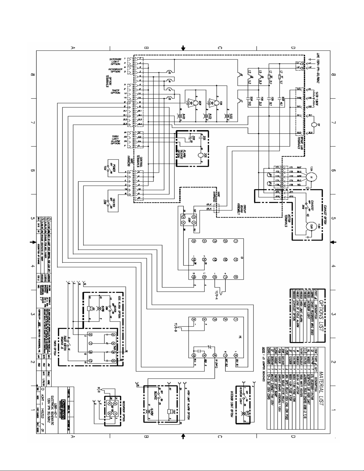
LBB1-23A-1 Drawing
38
Page 47

LBB1-23B-1 Parts
Part # Qty. Description
144755 1 Thermocouple
140097 2 Switch For Power And Heater
142861 1 Cord For Muffin Fan
057345 1 Relay Heater SSR
165051 1 Hi-Limit - Despatch L91
144749 1 Control - Des2000
007819 1 Heater 1.2kw 120/240v
145858 1 Door Seal
008057 2 Center Door Seal
148048 1 Door Pull
008199 2 Latch Ay
146010 1 LBB Exhaust Damper Assembly
145828 2 Standard Shelf
007281 1 Fan Wheel
008333 1 Motor 00.04hp 110/220v
015229 1 Control Compartment Muffin Fan
150132 1 Circuit Board 240v
117172 2 Fuse Atdr-03.00a Motor
123692 2 Fuse Atdr-6.00a Heater
39
Page 48

LBB1-23B-1 Drawing
40
Page 49

LBB1-43A-1 Parts
Part # Qty. Description
144755 1 Thermocouple
140097 2 Switch For Power And Heater
142861 1 Cord For Muffin Fan
057345 1 Relay Heater SSR
165051 1 Hi-Limit - Despatch L91
144749 1 Control - Des2000
054353 1 Heater 1.6kw 120/240v
145920 1 Door Seal
008057 2 Center Door Seal
148048 1 Door Pull
008199 2 Latch Ay
146010 1 LBB Exhaust Damper Assembly
146025 2 Standard Shelf
007281 1 Fan Wheel
008333 1 Motor 00.04hp 110/220v
006049 1 Control Compartment Muffin Fan
150131 1 Circuit Board 120v
123306 1 Fuse Atdr-04.00a Motor
144785 1 Fuse Atdr-17.5a Heater
41
Page 50
LBB1-43A-1 Drawing
42
Page 51

LBB1-43B-1 Parts
Part # Qty. Description
144755 1 Thermocouple
140097 2 Switch For Power And Heater
142861 1 Cord For Muffin Fan
057345 1 Relay Heater SSR
165051 1 Hi-Limit - Despatch L91
144749 1 Control - Des2000
054353 1 Heater 1.6kw 120/240v
145920 1 Door Seal
008057 2 Center Door Seal
148048 1 Door Pull
008199 2 Latch Ay
146010 1 LBB Exhaust Damper Assembly
146025 2 Standard Shelf
007281 1 Fan Wheel
008333 1 Motor 00.04hp 110/220v
015229 1 Control Compartment Muffin Fan
150132 1 Circuit Board 240v
117172 2 Fuse Atdr-03.00a Motor
144799 2 Fuse Atdr-8.00a Heater
43
Page 52

LBB1-43B-1 DRAWING
44
Page 53

LBB1-69A-1 Parts
Part # Qty. Description
144755 1 Thermocouple
140097 2 Switch For Power And Heater
142861 1 Cord For Muffin Fan
057345 1 Relay Heater SSR
165051 1 Hi-Limit - Despatch L91
144749 1 Control - Des2000
007819 1 Heater 2.4kw 120/240v
145725 1 Door Seal
008057 2 Center Door Seal
148048 1 Door Pull
008199 2 Latch Ay
146010 1 LBB Exhaust Damper Assembly
146024 2 Standard Shelf
094717 2 Reinforced Shelf
007281 1 Fan Wheel
008333 1 Motor 00.04hp 110/220v
006049 1 Control Compartment Muffin Fan
150131 1 Circuit Board 120v
123306 1 Fuse Atdr-04.00a Motor
134923 1 Fuse Atdr-25.00a Heater
45
Page 54

LBB1-69A-1 Drawing
46
Page 55

LBB1-69B-1 Parts
Part # Qty. Description
144755 1 Thermocouple
140097 2 Switch For Power And Heater
142861 1 Cord For Muffin Fan
057345 1 Relay Heater SSR
165051 1 Hi-Limit - Despatch L91
144749 1 Control - Des2000
007819 1 Heater 2.4kw 120/240v
145725 1 Door Seal
008057 2 Center Door Seal
148048 1 Door Pull
008199 2 Latch Ay
146010 1 LBB Exhaust Damper Assembly
146024 2 Standard Shelf
094717 2 Reinforced Shelf
007281 1 Fan Wheel
008333 1 Motor 00.04hp 110/220v
015229 1 Control Compartment Muffin Fan
150132 1 Circuit Board 240v
117172 2 Fuse Atdr-03.00a Motor
125562 2 Fuse Atdr-12.00a Heater
47
Page 56

LBB1-69B-1 Drawing
48
Page 57

LBB2-12-1 Parts
Part # Qty. Description
144755 1 Thermocouple
140097 2 Switch For Power And Heater
142861 1 Cord For Muffin Fan
057345 1 Relay Heater SSR
165051 1 Hi-Limit - Despatch L91
144749 1 Control - Des2000
007778 1 Heater 3.6kw 208/240v
145773 1 Door Seal
008057 3 Center Door Seal
148048 1 Door Pull
008199 2 Latch Ay
146010 1 LBB Exhaust Damper Assembly
145779 2 Standard Shelf
146023 2 Reinforced Shelf
007281 1 Fan Wheel
145783 1 Motor 00.25hp 110/220v
015229 1 Control Compartment Muffin Fan
150132 1 Circuit Board 240v
117172 2 Fuse Atdr-03.00a Motor
124475 2 Fuse Atdr-20.00a Heater
49
Page 58

LBB2-12-1 Drawing
50
Page 59

LBB2-18-1 Parts
Part # Qty. Description
144755 1 Thermocouple
140097 2 Switch For Power And Heater
142861 1 Cord For Muffin Fan
057345 1 Relay Heater SSR
165051 1 Hi-Limit - Despatch L91
144749 1 Control - Des2000
007818 3 Heater 1.2kw 120/240v
145814 1 Door Seal
008057 3 Center Door Seal
148048 1 Door Pull
008199 2 Latch Ay
146010 1 LBB Exhaust Damper Assembly
016471 2 Standard Shelf
105498 2 Reinforced Shelf
007281 1 Fan Wheel
145783 1 Motor 00.25hp 110/220v
015229 1 Control Compartment Muffin Fan
150132 1 Circuit Board 240v
117172 2 Fuse Atdr-03.00a Motor
124475 2 Fuse Atdr-20.00a Heater
51
Page 60

LBB2-18-1 Drawing
52
Page 61

LBB2-27-1 Parts
Part # Qty. Description
144755 1 Thermocouple
140097 2 Switch For Power And Heater
142861 1 Cord For Muffin Fan
057345 1 Relay Heater SSR
165051 1 Hi-Limit - Despatch L91
144749 1 Control - Des2000
007819 2 Heater 2.4kw 120/240v
145814 1 Door Seal
008057 3 Center Door Seal
148048 1 Door Pull
008199 2 Latch Ay
146010 1 LBB Exhaust Damper Assembly
016472 2 Standard Shelf
105497 2 Reinforced Shelf
007281 1 Fan Wheel
145783 1 Motor 00.25hp 110/220v
015229 1 Control Compartment Muffin Fan
150132 1 Circuit Board 240v
117172 2 Fuse Atdr-03.00a Motor
134923 2 Fuse Atdr-25.00a Heater
53
Page 62

LBB2-27-1 Drawing
54
Page 63

DESPATCH CUSTOMER SERVICE
Procedures and Customer
Responsibilities
To provide the most effective service to our customers under this warranty, all requests
for repairs are to be initiated by the Customer by telephone to the Despatch Service
Help Line, 800-473-7373. The Standard Period of Maintenance (SPM) is defined as
7:30 a.m. to 5 p.m. Monday through Thursday and 9:00 AM to 5:30 PM on Friday
Central Standard time, excluding weekends and Despatch Holidays. Calls placed within
the SPM will be handled as follows.
Help Line calls connect the customer with the Despatch Service Group. The technician
will record all pertinent information, including SERIAL and MODEL NUMBER of the
unit(s), the urgency and nature of the problem, and the name and phone number of the
caller or other contact. The technician will advise the Customer on suggested steps
and/or tests to either resolve the problem or help to confirm the diagnosis of the
problem.
Customer Agrees to cooperate in performing such tests and attempting to resolve the
problem as quickly as possible. Customer also agrees to replace minor parts such as
fuses, latches, etc. as instructed by Despatch Service Technicians. This approach has
Despatch and the Customer cooperating to effect the most expedient and cost effective
repair and minimize down time. If in Despatch's sole judgment, the equipment cannot
be repaired in this manner, an on-site visit by a Despatch authorized service
representative may be scheduled to repair the equipment. Customer agrees that, when
requested and authorized, such charges will be paid by the Customer within 30 days
from receipt of invoice.
55
Page 64

Attachment A - Sustained Service Support
At Despatch, long term customer satisfaction means more than responding quickly and
effectively to our customers' service requirements. It means offering comprehensive
customer support well beyond the scope of our initial contractual commitment.
Despatch's Service Products Group offers a Full Service Agreement package or a
Preventive Maintenance Plus agreement (PM+). These service products are unique in
the industry and offer the following benefits to our customer:
Priority response for minimum production interruption.
Preventive maintenance for longer product life.
Discount on parts and services where applicable.
Single payment for reduced billing expense.
Elimination of need for a separate purchase order for each service requested.
These extra service options are aimed at extending our new equipment productivity; we
will also extend the Despatch one year manufactured parts warranty for another 12
months. This bonus warranty is automatically yours when you purchase a service
agreement from Despatch within the first 12 months after shipment of the equipment.
56
Page 65

APPENDIX: OPTIONAL FEATURES
Protocol Plus Control Option
If the oven is equipped with the Despatch Protocol Plus controller, consult the Protocol
Plus manual (included).
Timer Option
The timer, which is set-up in hours, is used as a countdown timer. When the timer is on,
the delayed contact remains closed allowing power to the heater. During the first 20%
of the timing cycle, the first LED blinks. During the next 20% of the timing cycle, the first
LED stays on and the second LED blinks. The LED indicators continue in the same
manner until all LED’s are lit. When the LED’s are all lit, the timing cycle is complete,
the delayed contact opens and shuts off the heater. The heater will remain off until
either the TIMER switch is turned OFF, or resetting the timer.
Timer Displays and Switches
57
Page 66

Timer Operation
1. Turn the dials on the timer to the desired time.
2. Turn the Timer switch to ON. The timer is now counting down to zero.
3. Turn the HEATER switch to ON, if it is not already on.
4. When the timer counts down to zero the heater will shut off.
5. To reset the timer, turn the timer switch OFF then to ON.
6. To manually control the time, leave the timer switch OFF.
Timer Configuration
The timer is configured for XX.X hours from our facility. The timer can be easily set up
for different timing ranges. The following are instructions to configure the timer to suit
your needs.
1. Remove power from oven.
2. Remove top cover.
3. Remove socket from rear of timer.
4. Remove timer panel mounting bracket and remove timer from panel.
5. Using a small screwdriver, insert it the adjusting slots for the timer. The slots are
located behind the flange near the front of the timer. See Figure 8, above, for
locations of switches and displays.
a. Slide the switch to the desired range position.
b. Verify range by looking in face of timer in the range window.
c. Slide the switch to the desired decimal point position.
d. Verify decimal position by looking at the decimal position in face of timer.
6. Remount timer back into panel.
7. Reattach timer socket to timer.
58
Page 67

8. Replace top cover.
9. Apply power to oven, and follow instructions in the timer operation section.
Stand Assembly Instructions
1. Install four rubber grommets into holes in the stand. On LBB1-69 stands, the
rear grommets mount into the forward set of rear holes. On LBB2-12 stands the
rear grommets mount into the set of holes closest to the rear of the stand.
2. Place the oven on top of the stand. The four embossed areas in the bottom of
the oven should center in the grommets.
3. Using the self-drilling screw and large flat washer provided, install through each
embossed area as shown below.
Stand Assembly Components
59
Page 68

Stacking Kit Assembly Instructions
Side View of Oven
(1 per bracket)
Fr
ont View of Oven
(4 required)
1. Locate the four stacking kit brackets found in the kit.
2. Place each of the brackets on top of each of the four corners of one of the lower
ovens in the stack being assembled. Slide the angle of each bracket into the
slots in the embossed area on top of the oven. See the illustration below for
placement.
3. Use the four 10-16 x .50 screws included in the kit to attach the brackets to the
oven top.
4. Place the upper oven onto the lower one. The embossed “feet” on the upper
oven should fit into the brackets attached in the last three steps.
Stacking kit bracket
10-16 x .50 screw
Stacking Kit Assembly Components
60
Page 69

Timer Option with Audible and Visual
Alarm
This option sounds the alarm and a light comes on when the timer times out.
Turning the heater switch off will clear the alarm condition. Do not turn the heater
switch on before resetting the timer.
Turning the timer switch off will also clear the alarm condition but the heater will remain
on.
Wiring for this option is shown in the drawing section of this manual.
High Limit Alarm Option
This option sounds the alarm and a light comes on when a high limit condition occurs.
To silence the alarm horn, press the alarm silence switch; the light will remain on.
It is necessary to clear the high limit condition to clear the alarm. See the
troubleshooting section of this manual for solutions of high limit conditions.
It will be necessary to reset the high limit instrument whenever it has tripped. The high
limit instrument may be reset by first allowing the oven chamber to cool slightly (or by
setting the high limit instrument up several degrees) and pushing the black reset button.
The wiring for this option is shown on the electrical schematic in the drawing section of
this manual.
61
Page 70

Recorder Option
The circular chart recorder is used to record the user’s process. This is done by an
independent thermocouple. The charts used are 24 hour or 7 day. See the recorder
manufacturer’s manual supplied with this manual.
The wiring for this option is shown on the electrical schematic in the drawing section of
this manual.
62
 Loading...