

Page 1

LAC Series Oven Owner’s Manual ABOUT THIS MANUAL
ULTRAFLEX DRYING AND FIRING
FURNACE
MODELS 1000, 3615, 3630, 3640
C-204
VERSION 10
10/2008
LAC-6 SERIES OVEN
OWNER’S MANUAL
C-194
PN 150138
VERSION 16
3/2011
Version 106 1
All rights reserved. No part of the contents of this manual may be reproduced, copied or transmitted in any form or by any
means including graphic, electronic, or mechanical methods or photocopying, recording, or information storage and
retrieval systems without the written permission of Despatch Industries, unless for purchaser's personal use.
Copyright © 2011 by Despatch Industries.
Page 2
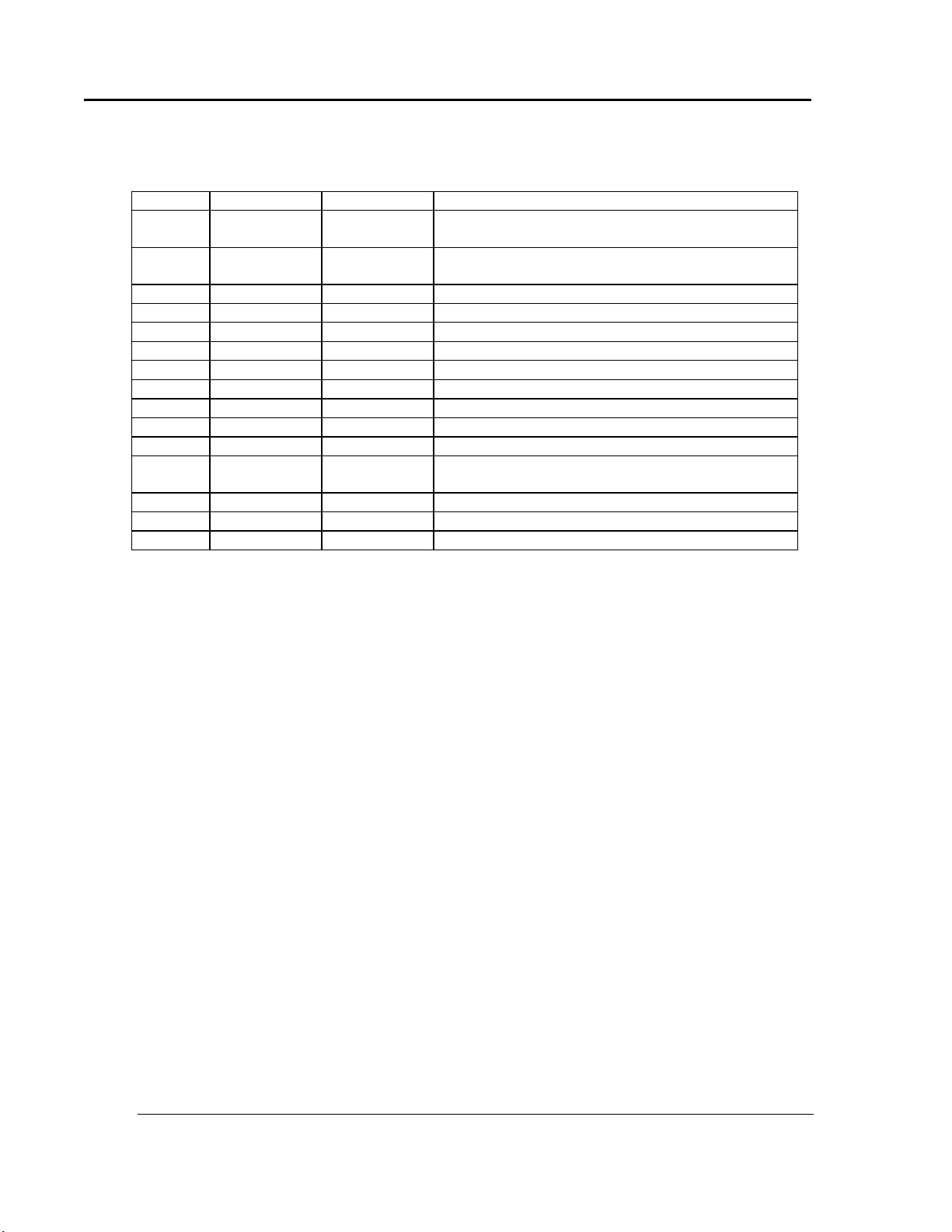
ABOUT THIS MANUAL LAC Series Oven Owner’s Manual
Revision
Date
Author
Description
B
Updated contents of Drawings Section
Updated Protocol Plus instructions
C
Added “Operating Environment” note to Operating
section. Updated drawings. Modified Preface
D
Modified per Rev C Protocol Plus software
E
Various corrections
F
Updated drawings
G
Updated Despatch warranty.
H
Updated drawing
I
Update to Protocol Plus Version 4
J
Ref. CAR 1165C
K
Changes to Unpacking and Inspection
L
Changed drawings
M
Revised Protocol numbers. Updated Despatch
address N
Updated warranty
O
Updated Protocol Plus Section
16
3/2011
K. Livingston
Revise format.
2 Version 10
Revision History
All rights reserved. No part of the contents of this manual may be reproduced, copied or transmitted in any form or by any
means including graphic, electronic, or mechanical methods or photocopying, recording, or information storage and
retrieval systems without the written permission of Despatch Industries, unless for purchaser's personal use.
Copyright © 2011 by Despatch Industries.
Page 3

LAC Series Oven Owner’s Manual ABOUT THIS MANUAL
Version 106 3
Table of Contents
1. About This Manual ................................................................................................. 5
1.1. Important User Information .......................................................................... 5
1.2. Manufacturer & Service ................................................................................ 6
1.3. Organization of this Manual ......................................................................... 6
1.4. Conventions .................................................................................................. 7
1.5. Specifications ................................................................................................ 8
1.5.1. Dimensions ................................................................................................ 8
1.5.2. Capacities .................................................................................................. 9
1.5.3. Power ....................................................................................................... 10
1.5.4. Temperature ............................................................................................ 11
2. Safety .................................................................................................................... 12
2.1. Safety Information ...................................................................................... 12
2.1.1. Lockout.................................................................................................... 12
2.1.1.1. Lockout Requirements ......................................................................... 12
2.1.1.2. Lockout Procedure ............................................................................... 12
2.1.2. Door and Panel ........................................................................................ 13
2.2. Maintenance ................................................................................................ 13
2.3. Electrical Power .......................................................................................... 13
2.4. Fire .............................................................................................................. 14
2.5. Equipment Lockout Requirements ............................................................. 15
2.5.1. Emergency Stop ...................................................................................... 15
3. Theory of Operation .............................................................................................. 16
3.1. The LAC-6 Series Oven.............................................................................. 16
3.2. Damper Control .......................................................................................... 17
3.2.1. Determining Damper Settings ................................................................. 17
3.2.1.1. Damper Full-Closed Position .............................................................. 17
3.2.1.2. Damper Full-Open Position ................................................................. 17
3.2.1.3. Other Damper Settings ........................................................................ 18
3.3. The Protocol Plus Controller ...................................................................... 19
4. Assembly & Setup ................................................................................................ 20
4.1. Unpack & Inspect the LAC-6 Series Oven ................................................. 20
4.1.1. If Damaged During Shipping .................................................................. 20
4.2. Set-up the LAC-6 Series Oven ................................................................... 20
4.2.1. Select Oven Location/Operating Environment ....................................... 20
4.2.2. Set-up Procedure ..................................................................................... 21
4.2.3. Wiring & Power Connections ................................................................. 22
4.2.3.1. Wire LAC-6 Models 2-12 and 2-18 .................................................... 23
4.3. MRC5000 Setup (Optional) ........................................................................ 25
5. Operation............................................................................................................... 26
5.1. Load Oven ................................................................................................... 26
5.2. Pre-Startup Checklist .................................................................................. 27
5.3. Operating Procedure ................................................................................... 28
5.3.1. Start Oven ................................................................................................ 28
5.3.2. Working with Protocol Plus Operating Modes ....................................... 28
6. Maintenance .......................................................................................................... 29
All rights reserved. No part of the contents of this manual may be reproduced, copied or transmitted in any form or by any
means including graphic, electronic, or mechanical methods or photocopying, recording, or information storage and
retrieval systems without the written permission of Despatch Industries, unless for purchaser's personal use.
Copyright © 2011 by Despatch Industries.
Page 4

ABOUT THIS MANUAL LAC Series Oven Owner’s Manual
4 Version 10
6.1. Checklist ..................................................................................................... 29
6.2. Lubrication .................................................................................................. 30
6.3. Routine Tests .............................................................................................. 30
6.4. Door Adjustment ......................................................................................... 30
6.5. Replacement Parts ....................................................................................... 30
6.5.1. Replace the Protocol Plus Controller ...................................................... 31
6.5.2. Replace Heater Unit ................................................................................ 31
6.5.3. Replace Fan Motor .................................................................................. 32
7. Troubleshooting .................................................................................................... 34
7.1. Troubleshooting Error Messages and Alarms............................................. 34
7.2. Troubleshooting Symptoms ........................................................................ 34
8. Appendices ............................................................................................................ 36
8.1. Standard Products Warranty ....................................................................... 36
8.2. Electrical Schematics .................................................................................. 37
Figures
Figure 1. LAC High-performance Bench-top Oven. ........................................................ 16
Figure 2. Horizontal Airflow through the LAC Oven. ..................................................... 16
Figure 3. Damper Positions............................................................................................... 17
Figure 4. Protocol Plus Displays and Control Buttons. .................................................... 19
Figure 5. LAC-6 Series Oven Nameplate. ........................................................................ 22
Figure 6. Rear Access Panel for Hard-Wired Connections. ............................................. 23
Figure 7. Hinged Panel for Simpler Access to Power Connections. ................................ 23
Figure 8. Power Connections at Main Circuit Board. ....................................................... 24
Figure 9. Remove Screws to Remove Floor Plate. ........................................................... 31
Figure 10. Heater Panel and Inlet Cone. ........................................................................... 31
Figure 11. Remove Screws to Remove Side Panels. ........................................................ 32
Figure 12. Remove Heater Panel by Removing Screw in Front Edge of Each Panel. ..... 32
Figure 13. LAC1-10-6 (Excerpt from drawing 146271D01)............................................ 38
Figure 14. LAC1-38A-6 (Excerpt from drawing 146273D01). ........................................ 38
Figure 15. LAC1-38B-6 (Excerpt from drawing 146275D01). ........................................ 38
Figure 16. LAC1-67-6 (Excerpt from drawing 146277D01)............................................ 38
Figure 17. LAC2-12-6 (Excerpt from drawing 146279D01)............................................ 38
Figure 18. LAC2-18-6 (Excerpt from drawing 146281E01). ........................................... 38
Tables
Table 1. MRC 5000 Settings. ............................................................................................ 25
Table 2. Error Messages and Next Steps. ......................................................................... 34
Table 3. Troubleshooting Oven Symptoms. ..................................................................... 35
All rights reserved. No part of the contents of this manual may be reproduced, copied or transmitted in any form or by any
means including graphic, electronic, or mechanical methods or photocopying, recording, or information storage and
retrieval systems without the written permission of Despatch Industries, unless for purchaser's personal use.
Copyright © 2011 by Despatch Industries.
Page 5

LAC Series Oven Owner’s Manual ABOUT THIS MANUAL
Values displayed on screens are examples only. Though
those values may be typical, contact Despatch Industries for
the final value.
Users of this equipment must comply with operating
procedures and training of operation personnel as required
by the Occupational Safety and Health Act (OSHA) of 1970,
Section 6 and relevant safety standards, as well as other
safety rules and regulations of state and local governments.
Refer to the relevant safety standards in OSHA and National
Fire Protection Association (NFPA), section 86 of 1990.
Version 106 5
1. About This Manual
1.1. Important User Information
Copyright © 2011 by Despatch Industries.
All rights reserved. No part of the contents of this manual may be reproduced, copied, or
transmitted in any form or by any means including graphic, electronic, or mechanical
methods or photocopying, recording, or information storage and retrieval systems without
the written permission of the publisher, unless it is for the purchaser's personal use.
Printed and bound in the United States of America.
The information in this manual is subject to change without notice and does not represent
a commitment on the part of Despatch Industries. Despatch Industries does not assume
any responsibility for any errors that may appear in this manual.
In no event will Despatch Industries be liable for technical or editorial omissions made
herein, nor for direct, indirect, special, incidental, or consequential damages resulting
from the use or defect of this manual.
All rights reserved. No part of the contents of this manual may be reproduced, copied or transmitted in any form or by any
means including graphic, electronic, or mechanical methods or photocopying, recording, or information storage and
retrieval systems without the written permission of Despatch Industries, unless for purchaser's personal use.
Copyright © 2011 by Despatch Industries.
Page 6
ABOUT THIS MANUAL LAC Series Oven Owner’s Manual
Danger!
Only fully-trained and qualified personnel should setup and
maintain this equipment. Improper setup and operation of this
equipment could cause an explosion that may result in
equipment damage, personal injury or possible death.
Global Headquarters
Contact
Service & Technical
Support
Despatch Industries
8860 207th Street
Lakeville, MN 55044
USA
International/Main: 1-952-469-5424
US toll free: 1-888-337-7282
Fax: 1-952-469-4513
info@despatch.com
www.despatch.com
Service: 1-952-469-8230
US toll free: 1-800-473-7373
Service @despatch.com
6 Version 10
The information in this document is not intended to cover all possible conditions and
situations that might occur. The end user must exercise caution and common sense when
installing or maintaining Despatch Industries products. If any questions or problems
arise, call Despatch Industries at 1-888-DESPATCH or 1-952-469-5424.
1.2. Manufacturer & Service
The LAC-6 Series Oven is manufactured by Despatch Industries.
Despatch has specialized in thermal processing for over 100 years. Technical expertise
gained over those years helps provide innovative solutions to critical applications in
vertical markets and cutting edge technology worldwide. Despatch products are backed
by a drive for long-term customer satisfaction and a strong sense of responsibility. The
worldwide network of factory-trained Service Professionals is available to support your
Despatch equipment. From full service preventive maintenance to routine repair and
certified calibration and uniformity, the Despatch service network is positioned to
respond to your business needs. Our service programs are customized to meet your
specific needs using our Advantage Service Assurance Program (ASAP). For more
information on ASAP, visit www.despatch.com.
1.3. Organization of this Manual
This owner’s manual contains the most comprehensive set of information for the
Despatch LAC-6 Series ovens, including installation instructions, theory of operation,
operating instructions, among other things.
Copyright © 2011 by Despatch Industries.
All rights reserved. No part of the contents of this manual may be reproduced, copied or transmitted in any form or by any
means including graphic, electronic, or mechanical methods or photocopying, recording, or information storage and
retrieval systems without the written permission of Despatch Industries, unless for purchaser's personal use.
Page 7
LAC Series Oven Owner’s Manual ABOUT THIS MANUAL
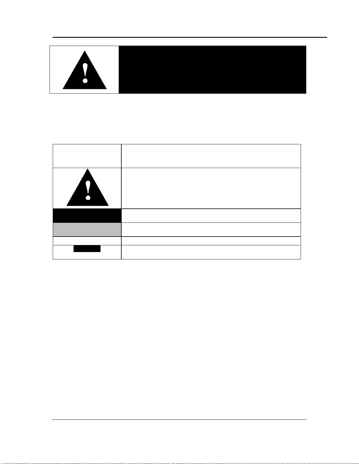
Danger!
Failure to heed warnings in this instruction manual and on the
oven could result in personal injury, property damage or death.
This icon signifies important information.
This icon signifies information that describes an unsafe condition
that may result in death, serious injury, or damage to the
equipment.
Danger!
A condition that may result in death, serious injury, or damage to
equipment.
Warning!
A condition that may result in serious injury or damage to
equipment.
Caution!
A condition that may result in damage to equipment or product.
LOG OUT
Reversed-out, Bold, 10pt Arial typeface indicates a specific key or
button on screen to click.
Version 106 7
1.4. Conventions
All rights reserved. No part of the contents of this manual may be reproduced, copied or transmitted in any form or by any
means including graphic, electronic, or mechanical methods or photocopying, recording, or information storage and
retrieval systems without the written permission of Despatch Industries, unless for purchaser's personal use.
Copyright © 2011 by Despatch Industries.
Page 8
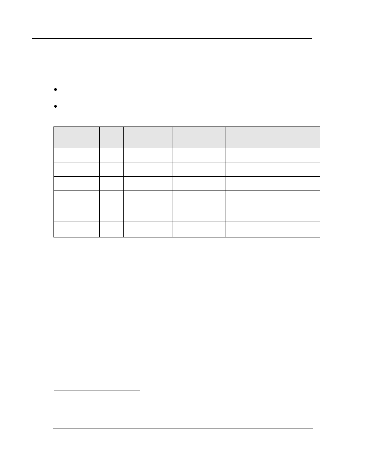
ABOUT THIS MANUAL LAC Series Oven Owner’s Manual
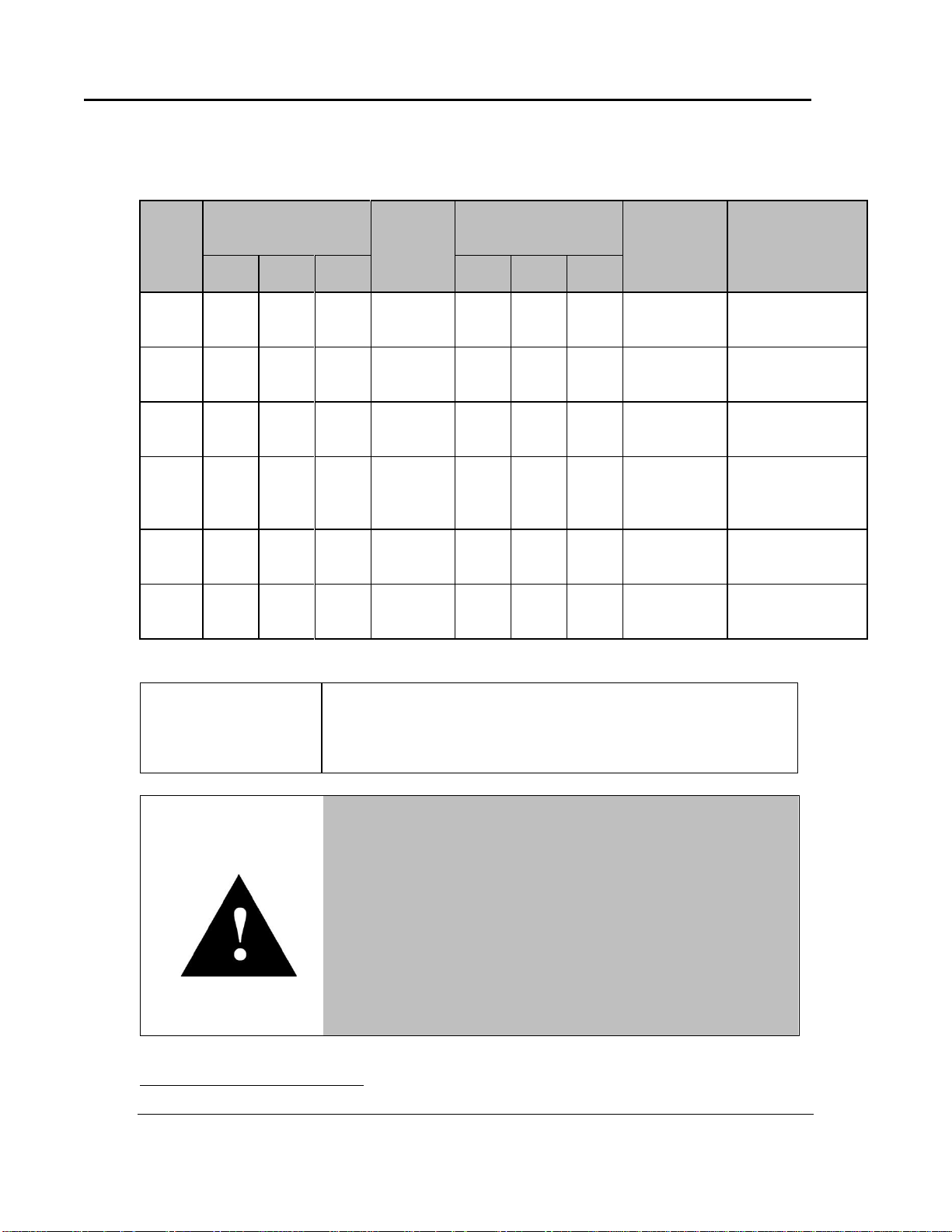
LAC
Model
No.
Chamber Size
in (cm)
Capacity
feet
3
(liters)
Overall Size
in (cm)
Max.
Number of
Shelf
Positions
Exhaust Diameter
Located on Back
of Chamber
in (cm)
W0F* D H W D
H
1-10
13.75
(35)
12
(28)
12
(31) 1 (33)
23
(58)
19
(48)
29.5
(75)
5
1
(2.5)
1-38A
18.75
(48)
18
(46)
19
(48)
3.7
(105)
28
(71)
25
(64)
35.5
(90)
9
2½
(6.4)
1-38B
18.75
(48)
18
(46)
19
(48)
3.7
(105)
28
(71)
25
(64)
35.5
(90)
9
2½
(6.4)
1-67
23.75
(60)
20
(51)
24
(61)
6.6
(187)
36
(91)
27
(69)
40.5
(103)
11
2½
(6.4)
2-12
23.75
(60)
24
(61)
36
(91)
12
(340)
36
(91)
31
(79)
52.5
(133)
17
2 x 2½
(6.4)
2-18
35.25
(91)
24
(61)
36
(91)
18
(510)
47
(119)
29.5
(75)
52.5
(133)
17
2 x 2½
(6.4)
The LAC-6 oven is not intended to process solvents or other
volatile or flammable materials. Oven exhaust is intended for
cooling purposes only.
Warning!
Do not place this oven in an environment harmful to electrical
components.
Placing this oven in an environment detrimental to electrical
components (for example, environments where carbon fibers,
coal dust or similar contaminants may be present) may result
in component failure.
Contact Despatch for options available to help prevent such
failures.
8 Version 10
1.5. Specifications
1.5.1. Dimensions
*
Allow 0.375" (0.95 cm) clearance on each side for shelf supports (3/4 in (1.9 cm) total).
All rights reserved. No part of the contents of this manual may be reproduced, copied or transmitted in any form or by any
means including graphic, electronic, or mechanical methods or photocopying, recording, or information storage and
retrieval systems without the written permission of Despatch Industries, unless for purchaser's personal use.
Copyright © 2011 by Despatch Industries.
Page 9

LAC Series Oven Owner’s Manual ABOUT THIS MANUAL
LAC-6 Model Number
1-10-6
1-38 A-6
& B-6
1-67-6
2-12-6
2-18-6
Maximum Load
Lbs (Kg)
150 (68)
175 (79)
250 (113)
300 (136)
300 (136)
Maximum Shelf Load
Lbs (Kg)
50 (23)
50 (23)
50 (23)
50 (23)
50 (23)
Exhaust
CFM
(LPS)
Adjustable
to 5
(2.4)
Adjustable
to 12
(5.6)
Adjustable
to 12
(5.6)
Adjustable
to 30
(14.2)
Adjustable
to 40
(18.9)
Recirculating Fan
CFM
(LPS)
150
(71)
300
(141)
300
(141)
600
(282)
600
(282)
H.P.
1/25 ¼ ¼
¼ x 2
¼ x 2
Approx. Weight Net
Lbs
(KG)
110
(50)
185
(84)
255
(116)
360
(163)
450
(204)
Shipping Weight
Lbs
(KG)
175
(79)
270
(123)
360
(163)
480
(218)
600
(272)
Version 106 9
1.5.2. Capacities
All rights reserved. No part of the contents of this manual may be reproduced, copied or transmitted in any form or by any
means including graphic, electronic, or mechanical methods or photocopying, recording, or information storage and
retrieval systems without the written permission of Despatch Industries, unless for purchaser's personal use.
Copyright © 2011 by Despatch Industries.
Page 10
ABOUT THIS MANUAL LAC Series Oven Owner’s Manual
Model
Volts
Amps
Hertz
Phase
Heater
KW
Cord and Plug
LAC 1-10-6
120
10.0
50/60 1 1
Included, 15 Amp (NEMA 5-15)
LAC 1-38A-6
120
16.5
50/60
1
1.6
Included, 20 Amp (NEMA 5-20)
LAC 1-38B-61F†
240
9.5
50/60
1
1.8
Included, 15 Amp (NEMA 6-15)
LAC 1-67-6†
240
12.0
50/60
1
2.4
Included, 15 Amp (NEMA 6-15)
LAC 2-12-6†
2F
‡
240
18.5
50/60
1
3.6
None, Hardwired
LAC 2-18-6† ‡
240
23.5
50/60
1
4.8
None, Hardwired
10 Version 10
1.5.3. Power
If the line voltage for your LAC-6 Series Oven varies more than 10% from the oven
voltage rating, electrical components such as relays and temperature controls may operate
erratically.
If the line voltage is lower than the oven voltage rating, heat-up time may be
significantly longer and motors may overload or run hot
If the line voltage is higher than the nameplate rating, motors may run hot and draw
excessive amperage
†
The LAC Series Oven designed for 240 volts (see oven nameplate) will operate satisfactorily on a
minimum of 208 Volts, but will result in 25% reduced heater output. If your power characteristic is lower,
contact Despatch Industries. An option is available to regain the full heater power when operating on 208V.
‡
The LAC 2-12 and LAC 2-18 must be hardwired to the electric supply using 10 AWG or larger wires
suitable for at least 75 °C (167 °F).
All rights reserved. No part of the contents of this manual may be reproduced, copied or transmitted in any form or by any
means including graphic, electronic, or mechanical methods or photocopying, recording, or information storage and
retrieval systems without the written permission of Despatch Industries, unless for purchaser's personal use.
Copyright © 2011 by Despatch Industries.
Page 11
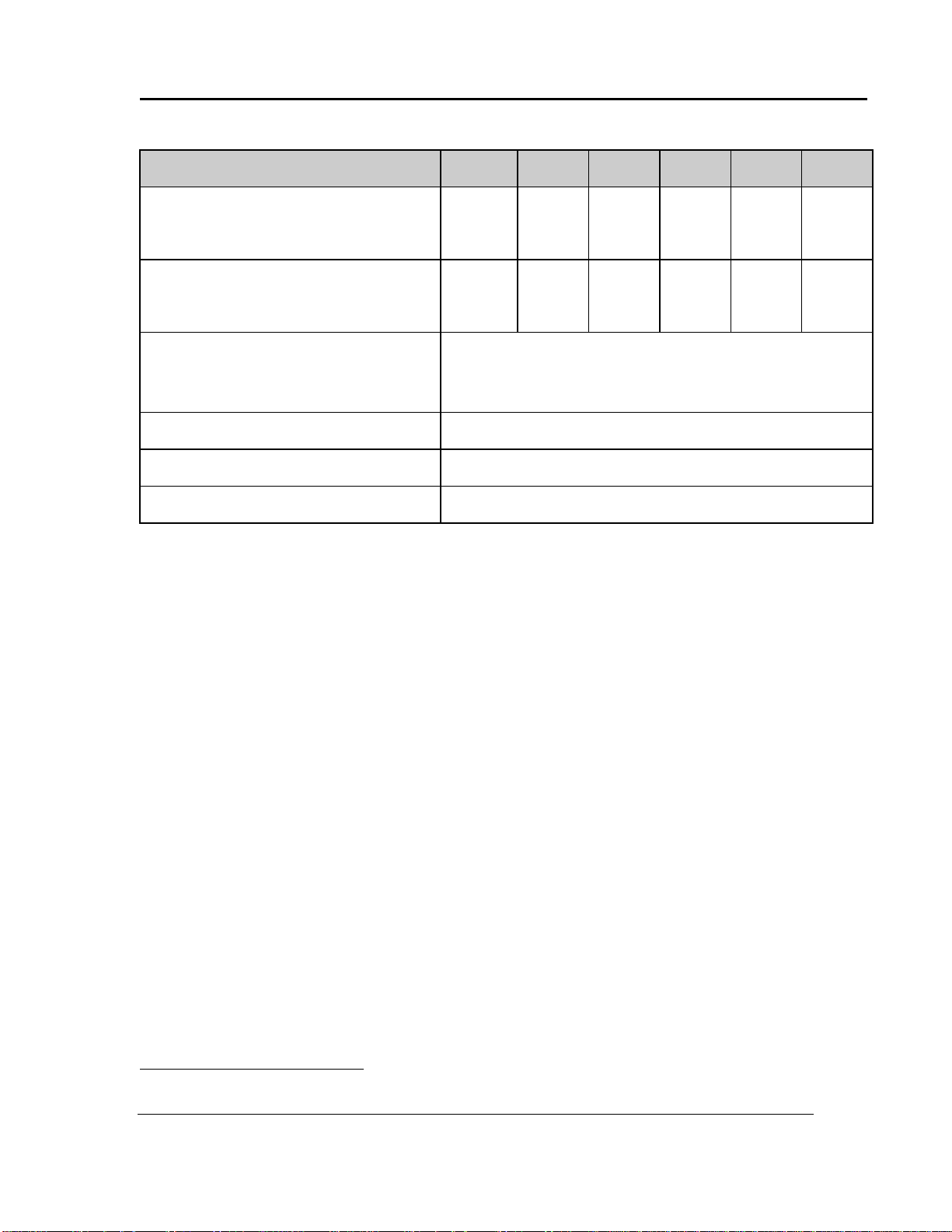
LAC Series Oven Owner’s Manual ABOUT THIS MANUAL
LAC-6 Model Number
1-10
1-38 A
1-38 B
1-67
2-12
2-18
Time to Temperature 40 °C – 100 °C
(approximate minutes 40 °C – 200 °C
with no load) 40 °C – 260 °C
8
25
40
9
32
60
6
22
36
6
20
34
6
19
31
4
17
29
Recovery Time - Door Open 100 °C
One Minute (approximate 200 °C
minutes with no load) 260 °C
1
3
7
1
6
14
1
4
8
1
3
5
1
6
9
1
4
8
Temperature Uniformity at 100 °C3F§
200 °C§
260 °C§
± 1 °C
± 2 °C
± 2.5 °C
Operating Range with 20 °C Ambient
40 °C – 260 °C
Control Stability
± 0.5 °C per 5 °C change in ambient
Repeatability
± 0.5° C
Version 106 11
1.5.4. Temperature
§
Figures are based on actual tests in an empty oven. Uniformity can vary slightly depending on unit and
operating conditions.
All rights reserved. No part of the contents of this manual may be reproduced, copied or transmitted in any form or by any
means including graphic, electronic, or mechanical methods or photocopying, recording, or information storage and
retrieval systems without the written permission of Despatch Industries, unless for purchaser's personal use.
Copyright © 2011 by Despatch Industries.
Page 12

SAFETY LAC Series Oven Owner’s Manual
Carefully follow the established Lock Out Tag Out policies of
your company in all cases.
Danger!
Electrical panels contain high voltage. Disconnect and lock out
the power supply before working inside any electrical panels.
Failure to lock out the power supply can result in death or injury.
12 Version 106
2. Safety
2.1. Safety Information
Do not work on the LAC-6 Series Oven without reading and understanding this section
which contains important information and warnings. Ignoring these warnings can result
in death, serious injury or damage to the machine and product.
2.1.1. Lockout
Machine lockout places the LAC-6 Series Oven into a zero energy state and prevents
accidental machine start up. Always follow the Lockout Procedure described in this
Section before cleaning, maintaining or repairing the LAC-6 Series Oven. An accidental
start-up, while working on the LAC-6 Series Oven, can result in serious injury or death.
2.1.1.1. Lockout Requirements
1. Every power source that can energize any element of the LAC-6 Series Oven must be
shut off at the closest possible power source. This includes air, water and electricity,
including the Disconnect Switch.
2. After energy sources are locked out, test to ensure circuits are de-energized.
2.1.1.2. Lockout Procedure
Personnel authorized to lockout equipment must have the necessary locks to perform the
lockout.
1. Physically disconnect all electrical power to the machine or lockout the appropriate
breaker or disconnects.
All rights reserved. No part of the contents of this manual may be reproduced, copied or transmitted in any form or by any
means including graphic, electronic, or mechanical methods or photocopying, recording, or information storage and
retrieval systems without the written permission of Despatch Industries, unless for purchaser's personal use.
Copyright © 2011 by Despatch Industries.
Page 13
LAC Series Oven Owner’s Manual SAFETY
Danger!
Electrical panels contain high voltage. Disconnect and lock out
the power supply before working inside any electrical panels.
Failure to lock out the power supply can result in death or injury.
Warning!
Do not place this oven in an environment harmful to electrical
components.
Placing this oven in an environment detrimental to electrical
components (for example, environments where carbon fibers,
coal dust or similar contaminants may be present) may result
in component failure.
Contact Despatch for options available to help prevent such
failures.
Version 10 13
2. Close all valves and bleed off any pressure.
3. Test for power by attempting a start with the machine controls.
4. Identify the Lockout Condition with a tag on the electrical disconnect and pneumatic
shut off valve.
5. When work is complete, remove all tags and restore the machine to its working state.
2.1.2. Door and Panel
The control panel on the LAC-6 Series Oven protect against hazards. Operation without
the control panel in place creates hazards that the control panel is intended to render safe
for personnel.
2.2. Maintenance
Only qualified and trained personnel should perform maintenance or repair.
2.3. Electrical Power
Only qualified and trained personnel should perform electrical maintenance or electrical
repair.
Copyright © 2011 by Despatch Industries.
All rights reserved. No part of the contents of this manual may be reproduced, copied or transmitted in any form or by any
means including graphic, electronic, or mechanical methods or photocopying, recording, or information storage and
retrieval systems without the written permission of Despatch Industries, unless for purchaser's personal use.
Page 14
SAFETY LAC Series Oven Owner’s Manual
Danger!
Contact with energized electrical sources may result in serious
injury or death.
Danger!
Always disconnect all power before extinguishing a fire.
Attempting to extinguish a fire in a machine connected to
electrical power can result in serious injury or death!
Warning!
Do not place this oven in an environment harmful to electrical
components.
Placing this oven in an environment detrimental to electrical
components (for example, environments where carbon fibers,
coal dust or similar contaminants may be present) may result
in component failure.
Contact Despatch for options available to help prevent such
failures.
14 Version 106
Before performing maintenance, disconnect all electrical power from the machine.
Use a padlock and lockout all disconnects feeding power to the machine.
Never clean, or repair the oven when in operation.
Unauthorized alterations or modifications to LAC-6 Series Oven are strictly
forbidden. Never modify any electrical circuits. Unauthorized modifications can
impair the function and safety of the LAC-6 Series Oven.
2.4. Fire
Keep the LAC-6 Series Oven clean and free of scrap materials, oil or solvents to prevent
the possibility of fire. In the event of fire, use a fire extinguisher as follows.
1. Leave door as it is.
2. De-energize the machine immediately by turning OFF the main power.
3. Shut off fuel (if applicable)
4. Call the fire department or extinguish the fire.
All rights reserved. No part of the contents of this manual may be reproduced, copied or transmitted in any form or by any
means including graphic, electronic, or mechanical methods or photocopying, recording, or information storage and
retrieval systems without the written permission of Despatch Industries, unless for purchaser's personal use.
Copyright © 2011 by Despatch Industries.
Page 15

LAC Series Oven Owner’s Manual SAFETY
Version 10 15
2.5. Equipment Lockout Requirements
To prevent injury or equipment damage during inspection or repair, the LAC-6 Series
Oven must be locked out.
2.5.1. Emergency Stop
When a risk of personal injury or damage to the LAC-6 Series Oven exists, turn OFF the
oven by removing/unplugging the cord. This shuts off all electrical power to the oven.
All rights reserved. No part of the contents of this manual may be reproduced, copied or transmitted in any form or by any
means including graphic, electronic, or mechanical methods or photocopying, recording, or information storage and
retrieval systems without the written permission of Despatch Industries, unless for purchaser's personal use.
Copyright © 2011 by Despatch Industries.
Page 16
THEORY OF OPERATION LAC Series Oven Owner’s Manual
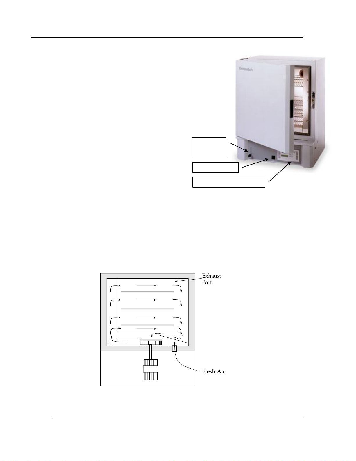
Damper
Control
Power Switch
Protocol Plus Controller
Figure 1. LAC High-performance Bench-top Oven.
Figure 2. Horizontal Airflow through the LAC Oven.
16 Version 106
3. Theory of Operation
3.1. The LAC-6 Series Oven
The LAC-6 high-performance bench-top
oven uses digitally-controlled, horizontal
recirculating airflow to ensure uniform
temperatures throughout the oven for fastprocessing (Figure 1). A high-volume fan
circulates air through perforated, stainless
steel walls to create a constant horizontal
airflow across all sections of the oven
(Figure 2). The result is proven reliability in
demanding production and laboratory
applications such as curing, drying,
sterilizing, aging and other process-critical
procedures.
The LAC-6 oven is especially useful for testing, preheating, sterilizing, drying, aging and
curing along with other production applications. The overall result is efficient
productivity under strenuous conditions. The chamber can be densely loaded without
interfering with the process. Air delivery temperature is within 1 °C of the number
appearing on the digital display. Fresh air intake is regulated by a panel-mounted damper
control, while the exhaust opening is fixed. The exhaust port, on the back of the oven, is
covered by a hat bracket.
All rights reserved. No part of the contents of this manual may be reproduced, copied or transmitted in any form or by any
means including graphic, electronic, or mechanical methods or photocopying, recording, or information storage and
retrieval systems without the written permission of Despatch Industries, unless for purchaser's personal use.
Copyright © 2011 by Despatch Industries.
Page 17
LAC Series Oven Owner’s Manual THEORY OF OPERATION
Warning!
Do not remove the hat bracket (located in rear of oven) as it
distributes exhaust air and protects the exhaust opening from
being completely covered.
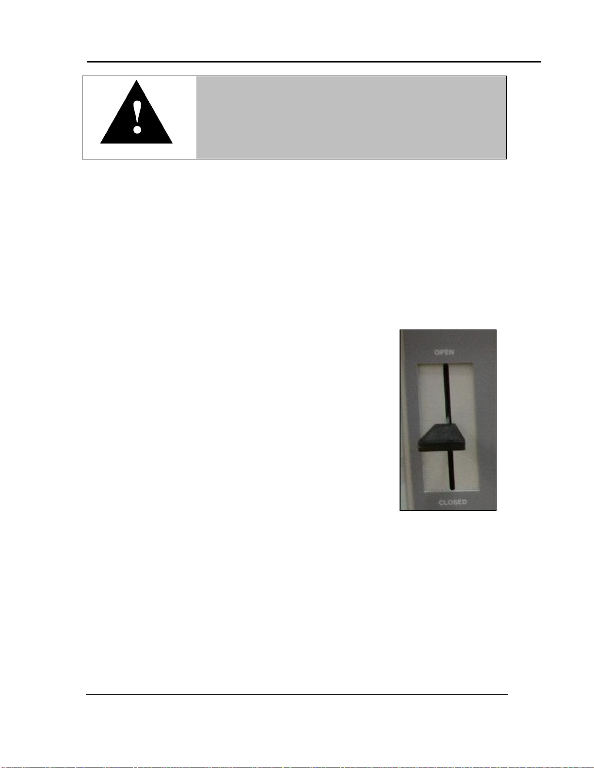
Figure 3. Damper Positions.
Version 106 17
3.2. Damper Control
The LAC-6 oven is equipped with a manually-adjustable damper mechanism. The
damper control arm is located on the front panel of the oven (Figure 1). The damper
adjustment controls the fresh air opening which, due to pressurization of the oven
chamber, controls the flow of exhaust. If the damper is in the full open position, the
maximum exhaust rate is achieved. If the damper is in the fully closed position, the
minimum exhaust rate is achieved.
3.2.1. Determining Damper Settings
The optimum setting for the damper depends on a variety of
factors. These factors include ambient environment
temperature, load conditions, load distribution, heat-up and
cool-down rates, desired temperature uniformity and most
importantly the desired operating temperature. Additionally,
engineering tradeoffs for each factor must be carefully
weighed. While considering each factor independently may
be too daunting, guidelines provide a simpler way to
determine damper settings.
In general, set the damper so the amount of fresh air flowing
into and exhausting from the chamber agrees with the
desired operating temperature conditions. The following
outline provides practical considerations for various damper
position settings (Figure 3).
3.2.1.1. Damper Full-Closed Position
The damper in full-closed position allows maximum attainable heat-up rates for the
chamber. In addition, the chamber uses minimum power to operate at the desired
temperature. In most cases, maintain the damper in the full-closed position to efficiently
operate at the maximum operating temperature for the chamber.
3.2.1.2. Damper Full-Open Position
The damper in full-open position allows minimum operating temperature for the
chamber. Friction heat from the air recirculation system builds up in the chamber. This
causes chamber temperature to rise slightly though the heating system is not ON. After
Copyright © 2011 by Despatch Industries.
All rights reserved. No part of the contents of this manual may be reproduced, copied or transmitted in any form or by any
means including graphic, electronic, or mechanical methods or photocopying, recording, or information storage and
retrieval systems without the written permission of Despatch Industries, unless for purchaser's personal use.
Page 18

THEORY OF OPERATION LAC Series Oven Owner’s Manual
When the damper is in the full-open position, the oven may not
be able to heat to the maximum oven operating temperature.
Over-pressuring the chamber can cause hot air to blow out
around the door seal and cause the area around the door to
be hot to the touch. Eliminate this hot air from entering the
room by closing the damper slightly until the air stops
blowing.
18 Version 106
the recirculation motor has been ON for an extended period of time, the chamber reaches
a thermal equilibrium temperature.
When the damper is not set to full-open position, the chamber has no way to readily
dissipate the heat generated by the friction. With the damper fully open, the thermal
equilibrium temperature is the minimum operating temperature of the chamber.
3.2.1.3. Other Damper Settings
The damper can be set to several other distinct operating positions. In most cases the
damper setting is influenced by two specific performance factors: uniformity and cooldown rates.
Chamber Uniformity
The system’s inside chamber pressure influences chamber uniformity. Pressure inside the
chamber depends on the amount of fresh air flowing into the chamber. When a large
volume of fresh air flows into the chamber, the chamber pressurizes slightly and overall
temperature uniformity improves. The slightly pressurized chamber produces the effect
of "pushing" air to the corners of the chamber. Typically the corners of the chamber
improve with respect to temperature distribution while the core of the chamber maintains
excellent uniformity characteristics regardless of damper position.
Pressurization of the chamber typically is a factor when the chamber is loaded heavily.
The best uniformity results, with respect to the product, are achieved when no more than
two-thirds of any inside chamber dimension are used. The best overall results are
achieved when the product(s) are located in the center of the chamber.
Cool-Down Rates
The more open the damper, the faster the cool-down.
All rights reserved. No part of the contents of this manual may be reproduced, copied or transmitted in any form or by any
means including graphic, electronic, or mechanical methods or photocopying, recording, or information storage and
retrieval systems without the written permission of Despatch Industries, unless for purchaser's personal use.
Copyright © 2011 by Despatch Industries.
Page 19

LAC Series Oven Owner’s Manual THEORY OF OPERATION
Figure 4. Protocol Plus Displays and Control Buttons.
Version 106 19
3.3. The Protocol Plus Controller
The Protocol Plus controller has two displays. A dedicated LED upper display shows the
oven temperature (Figure 4). A two line LCD lower display provides information on
control status, high limit temperature and allows changes to be made to the control
settings. Review the Protocol Plus Controller Owner’s Manual for more information.
All rights reserved. No part of the contents of this manual may be reproduced, copied or transmitted in any form or by any
means including graphic, electronic, or mechanical methods or photocopying, recording, or information storage and
retrieval systems without the written permission of Despatch Industries, unless for purchaser's personal use.
Copyright © 2011 by Despatch Industries.
Page 20

ASSEMBLY & SETUP LAC Series Oven Owner’s Manual
20 Version 106
4. Assembly & Setup
Assembly and Setup provides directions for unpacking and installing your LAC-6 Series
Oven.
4.1. Unpack & Inspect the LAC-6 Series Oven
Remove all packing materials and thoroughly inspect the oven for any damage that might
have occurred during shipment.
Note whether the carton and plastic cover sheet inside carton are still in good
condition
Observe all outside surfaces and corners of the oven for scratches and dents
Check oven controls and indicators for normal movement, bent shafts, cracks, chips
or missing parts such as knobs and lenses
Check the door and latch for smooth operation
4.1.1. If Damaged During Shipping
If damage occurred during shipping:
1. Contact the shipper immediately and file a written damage claim.
2. Contact Despatch Industries (1-800-473-7373 or 1-952-469-8230 or
service@despatch.com) to report your findings and to order replacement parts for
those damaged or missing. Send a copy of your filed damage claims to Despatch
industries (Despatch Industries, 8860 207th Street, Lakeville, MN 555044, USA).
3. Check the packing list to ensure you received all the specified components of the
oven system. If any items are missing, contact Despatch Industries to have missing
products forwarded to you. Your shipment should include:
One (1) Despatch oven
One (1) Instruction manual and Protocol Plus Manual
One (1) Warranty card
Two (2) Shelves
4. Complete the warranty card and mail it to Despatch within 15 days after receipt of the
equipment.
4.2. Set-up the LAC-6 Series Oven
4.2.1. Select Oven Location/Operating Environment
The Despatch LAC-6 Series oven is designed to operate in an industrial setting.
Despatch recommends the following environmental operating guidelines:
1. Place the oven on a flat, level solid foundation
All rights reserved. No part of the contents of this manual may be reproduced, copied or transmitted in any form or by any
means including graphic, electronic, or mechanical methods or photocopying, recording, or information storage and
retrieval systems without the written permission of Despatch Industries, unless for purchaser's personal use.
Copyright © 2011 by Despatch Industries.
Page 21
LAC Series Oven Owner’s Manual ASSEMBLY & SETUP
Warning!
All grounding and safety equipment must be in compliance with
applicable codes, ordinances and accepted safe practices.
Warning!
Do not use the oven in wet, corrosive or explosive atmospheres
unless this oven is specifically designed for a special
atmosphere.
Version 106 21
2. Do not expose the oven to excessive external vibration
3. Do not remove electrical cabinet covers
4. Where excessive particulate matter is present, such as on a construction site or coal
processing, Despatch recommends periodic (usually monthly) cleaning of all
electrical compartments.
5. Ensure the power supply meets Despatch specifications. If the facility power supply
is not stable, Despatch recommends a line conditioner.
4.2.2. Set-up Procedure
1. Place oven on bench top or optional cabinet base.
a. Ensure a minimum of two (2) inches (5.1 cm) clearance in the rear of oven to
provide proper ventilation. The oven may be placed next to another cabinet, or
next to another oven, with three (3) inch (7.6 cm) clearance (the doors will still
open).
b. Ensure oven is level and plumb for proper heat distribution and operation of all
mechanical components.
2. Identify correct power source indicated on the specification nameplate.
3. Plug or hardwire oven directly to the electric supply.
All rights reserved. No part of the contents of this manual may be reproduced, copied or transmitted in any form or by any
means including graphic, electronic, or mechanical methods or photocopying, recording, or information storage and
retrieval systems without the written permission of Despatch Industries, unless for purchaser's personal use.
Copyright © 2011 by Despatch Industries.
Page 22
ASSEMBLY & SETUP LAC Series Oven Owner’s Manual
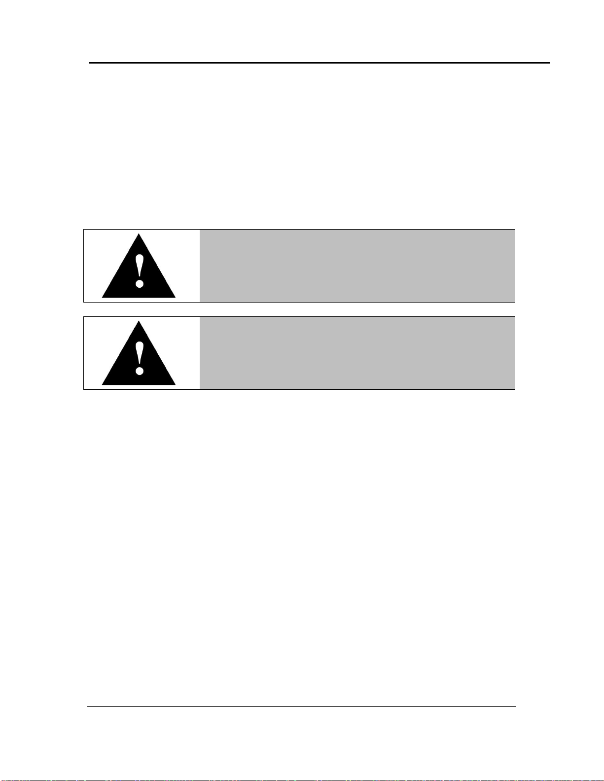
Read the Model LAC-6 name plate (top of oven or top of control
area under the door) for proper power requirements before
proceeding with wiring and power connections (Figure 5).
Danger!
All grounding and safety equipment must be in compliance with
applicable codes, ordinances and accepted safe practices.
Figure 5. LAC-6 Series Oven Nameplate.
22 Version 106
4.2.3. Wiring & Power Connections
Models LAC 1-10, 1-38A, 1-38B, and 1-67 come equipped with an appropriate plug and
cord. Models LAC 2-12 and 2-18 must be hardwired to the electric supply using 10 AWG
or larger wires suitable for at least 75 °C (167 °F).
All rights reserved. No part of the contents of this manual may be reproduced, copied or transmitted in any form or by any
means including graphic, electronic, or mechanical methods or photocopying, recording, or information storage and
retrieval systems without the written permission of Despatch Industries, unless for purchaser's personal use.
Copyright © 2011 by Despatch Industries.
Page 23

LAC Series Oven Owner’s Manual ASSEMBLY & SETUP
Power cord
fitting or
conduit
Access plate to
assist in tightening
conduit fitting
For units that must be hardwired or where a power cord is
shipped loose, run the power lines from the rear of the oven to
the front control panel.
Figure 6. Rear Access Panel for Hard-Wired Connections.
Figure 7. Hinged Panel for Simpler Access to Power Connections.
Version 106 23
4.2.3.1. Wire LAC-6 Models 2-12 and 2-18
1. Open the knock-out near the rear-access panel (Figure 6).
2. Turn hinged front panel latches ¼ turn for easy access to access power connection
(Figure 7).
All rights reserved. No part of the contents of this manual may be reproduced, copied or transmitted in any form or by any
means including graphic, electronic, or mechanical methods or photocopying, recording, or information storage and
retrieval systems without the written permission of Despatch Industries, unless for purchaser's personal use.
Copyright © 2011 by Despatch Industries.
Page 24

ASSEMBLY & SETUP LAC Series Oven Owner’s Manual
Connect
power at
main circuit
board
terminals L1
and L2.
Figure 8. Power Connections at Main Circuit Board.
24 Version 106
3. Connect power at main circuit board (access by opening hinged control panel),
terminals L1 and L2 (Figure 8).
a. Tighten terminals on the circuit board to 10.6 to 13.2 lb-in (1.2 to 1.5 nM)
b. Attach the ground wire to the ground buss on the panel.
c. Close hinged control panel after attaching the power supply wires or cord.
All rights reserved. No part of the contents of this manual may be reproduced, copied or transmitted in any form or by any
means including graphic, electronic, or mechanical methods or photocopying, recording, or information storage and
retrieval systems without the written permission of Despatch Industries, unless for purchaser's personal use.
Copyright © 2011 by Despatch Industries.
Page 25
LAC Series Oven Owner’s Manual ASSEMBLY & SETUP
Refer to instructions provided recorder manufacturer for more
specific installation notes.
Parameter Code
Degrees C
Degrees F
Inps
18
18
Icor 0 0
diSP
On
On
dPOS
0 0 EUU**
400
752
EUL**
0
32
ChUP
400
800*
ChLO
0 0 DFF
1
1
Version 106 25
4.3. MRC5000 Setup (Optional)
Temperature is retransmitted to the MRC5000 recorder from the controller. Set up the
recorder by:
1. Ensure hardware jumper JU1 is in place for the 5 VDC setting (Refer to MRC5000
Manual included).
2. Move Mode to PROG/TEST/CAL to display Prog.
3. Press ▼ twice to display Inps. Move to each Parameter Code using ▼or ▲. Adjust
each Parameter Code using the settings in Table 2.
4. After adjusting all settings, move Mode to RUN. Display on both the Recorder and
controller should read the same.
Table 1. MRC 5000 Settings.
* Change 0-400 chart paper to 0-800 chart paper. Depending on the equipment used, 0-
600 paper may be used if the maximum temperature is 500 degrees F.
** These values must match the settings RetOutLo and RetOutHi on the Protocol Plus
Control page. For example, if RetOutLo is 32, EUL must read 32.
All rights reserved. No part of the contents of this manual may be reproduced, copied or transmitted in any form or by any
means including graphic, electronic, or mechanical methods or photocopying, recording, or information storage and
retrieval systems without the written permission of Despatch Industries, unless for purchaser's personal use.
Copyright © 2011 by Despatch Industries.
Page 26

OPERATION LAC Series Oven Owner’s Manual
Users and operators of this oven must comply with operating
procedures and training of operating personnel as required by
the Occupational Safety and Health Act (OSHA) of 1970, Section
5 and relevant safety standards, and other safety rules and
regulations of state and local governments. Refer to the relevant
safety standards in OSHA and National Fire Protection
Association (NFPA), Section 86 of 1990.
Despatch Industries cannot be responsible for either the
process or process temperature used, or for the quality of the
product being processed. It is the responsibility of the
purchaser and operator to see that the product undergoing
processing in a Despatch oven is adequately protected from
damage.
Carefully following the instructions in this manual will help the
purchaser and operator in fulfilling that responsibility.
Caution!
Always place loads on the shelves provided to avoid possible
uneven heating and damage to the oven.
Warning!
Do not use the oven in wet, corrosive or explosive atmospheres
unless this oven is specifically designed for a special
atmosphere.
26 Version 106
5. Operation
5.1. Load Oven
Avoid spilling on the heater elements or oven floor when loading the oven. Do not place
the load on the oven floor plate. Placing the load on the oven floor may cause the load to
heat unevenly and the weight may cause shorting out of the heater elements. Use the
shelves provided.
All rights reserved. No part of the contents of this manual may be reproduced, copied or transmitted in any form or by any
means including graphic, electronic, or mechanical methods or photocopying, recording, or information storage and
retrieval systems without the written permission of Despatch Industries, unless for purchaser's personal use.
Copyright © 2011 by Despatch Industries.
Page 27

LAC Series Oven Owner’s Manual OPERATION
Warning!
Do not use flammable solvent or other flammable material in this
oven. Do not process closed containers of any substance or
liquid in this oven because they may explode under heat.
Version 106 27
The two shelves are designed to be pulled out about halfway without tipping. Do not
overload the shelves (Refer to Support Capacity listed in Section 1.5.2). Distribute the
workload evenly so airflow is not restricted. Do not overfill your oven. The workload
should not take up more than two-thirds of any dimension of the inside cavity.
5.2. Pre-Startup Checklist
□ Know the system. Read this manual carefully. Make use of its instructions and
explanations. Safe, continuous, satisfactory, trouble-free operation depends primarily
on your degree of understanding the system and your willingness to keep all parts in
proper operating condition.
□ Check line voltage. Voltage must correspond to nameplate requirements of motors
and controls. A wrong voltage can result in serious damage. Refer to Section 1.5.4 for
more information.
□ Check fresh air and exhaust openings. Do not be careless about restrictions in and
around the fresh air and exhaust openings and stacks. Under no condition can they be
permitted to become so filled with dirt that they reduce airflow.
□ Ventilation. An exhaust opening in the rear of the unit is covered by a hat bracket. Do
not remove the hat bracket as it protects the exhaust opening from being completely
covered.
□ Helpful hints:
o For drying ovens, open vent to prevent buildup of moisture.
o For sample heating, close vent when no ventilation is required.
All rights reserved. No part of the contents of this manual may be reproduced, copied or transmitted in any form or by any
means including graphic, electronic, or mechanical methods or photocopying, recording, or information storage and
retrieval systems without the written permission of Despatch Industries, unless for purchaser's personal use.
Copyright © 2011 by Despatch Industries.
Page 28

OPERATION LAC Series Oven Owner’s Manual
For fastest oven heat-up time, close the fresh-air vent. After the
desired temperature is reached, the vent may be adjusted as
needed.
28 Version 106
5.3. Operating Procedure
5.3.1. Start Oven
1. Start fan
a. Open oven door
b. Press Power Switch to ON (Figure 1). Listen for the recirculating fan to start.
c. Shut oven door
d. Check that control display turns ON.
2. Operate temperature control as desired by following the control operation instructions
to follow.
5.3.2. Working with Protocol Plus Operating Modes
Refer to the Protocol Plus Controller Owner’s Manual for specifics on working with the
controller.
All rights reserved. No part of the contents of this manual may be reproduced, copied or transmitted in any form or by any
means including graphic, electronic, or mechanical methods or photocopying, recording, or information storage and
retrieval systems without the written permission of Despatch Industries, unless for purchaser's personal use.
Copyright © 2011 by Despatch Industries.
Page 29

LAC Series Oven Owner’s Manual MAINTENANCE
Warning!
Do not attempt any service on this oven before opening the
main power disconnect switch.
Warning!
Do not place this oven in an environment harmful to electrical
components.
Placing this oven in an environment detrimental to electrical
components (for example, environments where carbon fibers,
coal dust or similar contaminants may be present) may result
in component failure.
Contact Despatch for options available to help prevent such
failures.
Version 106 29
6. Maintenance
6.1. Checklist
Keep equipment clean. Gradual dirt accumulation retards airflow. A dirty oven can
result in unsatisfactory operation such as unbalanced temperature in the work
chamber, reduced heating capacity, reduced production, overheated components, and
the like. Keep the walls, floor and ceiling of the oven work chamber free of dirt and
dust. Floating dust or accumulated dirt may produce unsatisfactory work results.
Keep all equipment accessible. Do not permit other materials to be stored or piled
against it.
Protect controls against excessive heat—particularly controls, motors or other
equipment containing electronic components. Temperatures greater than 51.5°C
(125°F) should be avoided.
Establish maintenance and checkup schedules. Do this promptly and follow the
schedules faithfully. Careful operation and maintenance will be more than paid for in
continuous, safe and economical operation.
Maintain equipment in good repair. Make repairs immediately. Delays may be
costly in added expense for labor and materials and in prolonged shut down.
Practice safety. Make it a prime policy to know what you are doing before you do it.
Make caution, patience, and good judgment the safety watchwords for the operation
of your oven.
Copyright © 2011 by Despatch Industries.
All rights reserved. No part of the contents of this manual may be reproduced, copied or transmitted in any form or by any
means including graphic, electronic, or mechanical methods or photocopying, recording, or information storage and
retrieval systems without the written permission of Despatch Industries, unless for purchaser's personal use.
Page 30

MAINTENANCE LAC Series Oven Owner’s Manual
30 Version 106
6.2. Lubrication
Fan motor bearings are permanently lubricated. All door latches, hinges, door operating
mechanisms, bearing or wear surfaces should be lubricated to ensure easy operation.
6.3. Routine Tests
Test LAC-6 Series Oven functions regularly and carefully for best performance. Safety of
personnel and maintenance of your equipment may depend on the proper operation of
any of the temperature control functions.
Check that the heater LED is cycling on and off, indicating the heater is working.
Check the high limit function to make sure it is working properly:
1. Press Select and go to Manual Mode. Enter a control setpoint value at least 20°F
(11°C) lower than the current process temperature.
2. Press Menu and lower the high limit setpoint to a value just below the current
process temperature.
3. Press Run
4. The high limit alarm indicator will flash and a high limit alarm message will
display.
5. Press Stop.
6. Press Reset.
7. Return the control setpoint and high limit setpoint values to their original values.
6.4. Door Adjustment
To increase or decrease latch tension, or to gain a better door seal on the latch side:
Turn the door strike in or out on its threads by loosening the allen head set screw.
If necessary, adjust the vertical alignment of the strike to increase or decrease latch
tension.
1. Loosen the two screws on the latch strike and sliding the strike up or down on its
slots
2. After positioning the strike, tighten the screws.
6.5. Replacement Parts
To order or return parts, contact Despatch Service & Technical Support. When returning
parts, a Despatch representative will provide an MRA (Material Return Authorization)
number. Attach the MRA number to the returned part for identification. When ordering
parts, expedite the process by giving the model number, serial number and part number.
All rights reserved. No part of the contents of this manual may be reproduced, copied or transmitted in any form or by any
means including graphic, electronic, or mechanical methods or photocopying, recording, or information storage and
retrieval systems without the written permission of Despatch Industries, unless for purchaser's personal use.
Copyright © 2011 by Despatch Industries.
Page 31

LAC Series Oven Owner’s Manual MAINTENANCE
Global Headquarters
Contact
Service & Technical
Support
Despatch Industries
8860 207th Street
Lakeville, MN 55044
USA
International/Main: 1-952-469-5424
US toll free: 1-888-337-7282
Fax: 1-952-469-4513
info@despatch.com
www.despatch.com
Service: 1-952-469-8230
US toll free: 1-800-473-7373
Fax: 1- 952-469-8193
Service @despatch.com
Warning!
Disconnect the main power switch or power cord before
attempting any repair or adjustment.
Figure 9. Remove Screws to Remove Floor Plate.
Figure 10. Heater Panel and Inlet Cone.
Version 106 31
6.5.1. Replace the Protocol Plus Controller
Refer to the Protocol Plus Owner’s Manual for instructions on replacing the
Protocol Plus Controller.
6.5.2. Replace Heater Unit
Tools needed: 3/8" wrench,
T20 Torx bit driver
1. Remove the floor plate.
a. Remove the
screws from the
floor plate
(Figure 9).
b. Lift the floor plate out of the
oven to expose heater panel/inlet
cone (Figure 10).
All rights reserved. No part of the contents of this manual may be reproduced, copied or transmitted in any form or by any
means including graphic, electronic, or mechanical methods or photocopying, recording, or information storage and
retrieval systems without the written permission of Despatch Industries, unless for purchaser's personal use.
Copyright © 2011 by Despatch Industries.
Page 32

MAINTENANCE LAC Series Oven Owner’s Manual
Before disconnecting leads, carefully
diagram (or note) which wires connect to
which terminals.
Figure 11. Remove Screws to
Remove Side Panels.
Figure 12. Remove Heater Panel by Removing
Screw in Front Edge of Each Panel.
32 Version 106
2. Remove side walls by removing the screws on the
front edge of each panel (Figure 11).
3. Disconnect the heater leads from heater element with
wrench.
4. Unscrew the screws holding the heater frame to the
oven body (Figure 12).
5. Remove heater and discard.
6. Screw down the new heater frame.
7. Attach the heater leads to appropriate
terminals.
8. Replace and screw in interior floor and side
panels.
6.5.3. Replace Fan Motor
Tools needed: T20 Torx bit driver, 5/32 inch Allen wrench, one quarter (¼) inch socket
set
1. Remove the floor plate.
a. Remove the screws from the floor plate (Figure 9).
b. Lift the floor plate out of the oven to expose heater panel/inlet cone
(Figure 10).
c. Lift the floor plate out of the oven to expose heater panel/inlet cone
(Figure 10).
2. Remove side walls by removing the screws on the front edge of each panel
(Figure 11).
3. Disconnect the heater leads from heater element with wrench.
All rights reserved. No part of the contents of this manual may be reproduced, copied or transmitted in any form or by any
means including graphic, electronic, or mechanical methods or photocopying, recording, or information storage and
retrieval systems without the written permission of Despatch Industries, unless for purchaser's personal use.
Copyright © 2011 by Despatch Industries.
Page 33

LAC Series Oven Owner’s Manual MAINTENANCE
Before disconnecting leads, carefully diagram (or note) which
wires connect to which terminals.
Version 106 33
4. Unscrew the screws holding the heater frame to the oven body (Figure 12).
5. Unplug the motor harness from the circuit board and remove motor and heater
ground wires from ground stud.
6. Unplug heater leads from circuit board and thermocouple leads from control.
7. Pull off fresh air damper handle from damper arm.
8. Remove screws holding fresh air damper arm assembly to control panel.
9. Remove the chamber floor plate.
a. Remove the screws from the floor plate.
b. Lift the floor plate out of the oven.
10. Remove the left side wall.
11. Remove fan and heater plug assembly from oven by lifting on the air outlet of the
assembly and pushing from underneath.
12. Remove heater (do not disconnect wires).
13. Remove the fan inlet plate.
14. Loosen the set screws (2) on fan wheel and remove wheel.
15. Remove the screws (4) holding the fan motor in place.
16. Remove the fan motor.
17. Install the fan motor.
a. Insert shaft seal onto shaft.
b. Insert the shaft into shaft collar.
c. Fasten motor to plug assembly with the four screws.
18. Install fan wheel onto motor shaft.
19. Replace and fasten the fan inlet cover.
20. Adjust the fan wheel for 3/16 inch clearance between the wheel and the inlet ring
and tighten the set screws on the fan wheel. Check that the set screws hit the flats
machined into the motor shaft.
21. Replace and fasten heater.
22. Replace fan and heater plug assembly in oven body.
23. Replace left side wall.
24. Replace and fasten floor plate.
25. Replace fresh air damper arm assembly.
26. Replace fresh air damper handle.
27. Connect heater leads to circuit board.
28. Connect motor wire harness and fasten motor and heater ground wires to ground
stud.
29. Connect thermocouple wires to control.
30. Replace control panel in oven body.
All rights reserved. No part of the contents of this manual may be reproduced, copied or transmitted in any form or by any
means including graphic, electronic, or mechanical methods or photocopying, recording, or information storage and
retrieval systems without the written permission of Despatch Industries, unless for purchaser's personal use.
Copyright © 2011 by Despatch Industries.
Page 34
TROUBLESHOOTING LAC Series Oven Owner’s Manual
Alarm Status
Possible Problem
Next Step
Hi-Limit LED flashing
Problem with thermocouple
Hi-limit setpoint has been
exceeded.
Once the problem has corrected,
press Reset.
Soak LED flashing
Oven temperature has not
entered (or dropped out of) the
soak band and the soak timer
has stopped
Program a slower ramp rate or if
oven is not heating check heater
circuit.
Top LED displays
OPEN and lower LCD
displays CONTROL
SENS ERR
Control thermocouple is
disconnected or broken
Repair or replace the thermocouple.
Lower LCD displays HI
LIM SENS ERR
Hi limit thermocouple is
disconnected or broken
Repair or replace the thermocouple.
Lower LCD displays
HIGH LIMIT ALARM
Hi limit temperature setpoint
has been exceeded
Determine if:
the setting is too close to the
setpoint
the SSR is defective
calibration is incorrect
The lower LCD intermittently display HL Temp. This is not an
error message, but the Hi limit thermocouple temperature
reading.
The circuit board mounted on the control panel has three status
LED indicators to help troubleshoot if the oven is not heating:
If LED 1 is not lit, check 2F and 3F (control fuses), or power
switch.
If LED 1 and LED 3 are lit but not LED 2, check high limit
(and optional door switch, if installed).
If all three LEDs are lit, check 1F and 4F (heater fuses), SSR,
heater, and heater relays.
34 Version 106
7. Troubleshooting
7.1. Troubleshooting Error Messages and Alarms
Table 3 lists the more common error messages, the possible problems and remedies.
Table 2. Error Messages and Next Steps.
7.2. Troubleshooting Symptoms
Table 4 lists symptoms, probably causes and suggested remedies.
Copyright © 2011 by Despatch Industries.
All rights reserved. No part of the contents of this manual may be reproduced, copied or transmitted in any form or by any
means including graphic, electronic, or mechanical methods or photocopying, recording, or information storage and
retrieval systems without the written permission of Despatch Industries, unless for purchaser's personal use.
Page 35

LAC Series Oven Owner’s Manual TROUBLESHOOTING
Symptom
Possible Cause
Next Step
Failure to heat
or heats to
only 35-50
degrees C
No power
Check power source and/or oven and wall fuses
Broken or frayed cord
Replace with new cord
Burned out heater
Replace heater (see Warranty Section 8.1)
Protocol™ malfunction
Replace controller
Loose wire connections
Disconnect power and check connections behind control
panel
Heater relay failure
Replace circuit board
Door switch failure
Replace door switch
Slow heat-up
Improperly loaded
Reduce load or redistribute load in chamber
Low line voltage
Supply sufficient power and proper connections. Check
for circuit overload
Heating element(s) are
burned out
Replace burned out element (see Warranty Section 8.1)
240 volt oven is connected
to a 208V line
Raise line voltage to a 240 volt line or modify oven for
208V operation (consult factory)
Fan motor failure
Replace fan motor
Frequent
heater
element out
Harmful fumes generated
by load
Increase vent opening or discontinue process
Spillage or splattering of
material on heater
elements
Disconnect power and clean oven chamber and elements
Overheating oven
Check the Hi-limit
Erratic or
inaccurate
temperature
Protocol™ Plus Controller
malfunction
Replace Protocol™ Plus Controller
Improper tuning
parameters
Check tuning parameters
Protocol™ Plus Controller
miscalibration
Recalibrate Protocol™ Plus Controller (See Protocol Plus
Owner’s Manual, sections on Calibration)
Hi-limit setting
Hi-limit should be 10-25°C higher than setpoint
Improper offset
Check zone calibration
Excess
surface or
door
temperature
Door seal deterioration
Replace door seal
Improper
airflow
Fan motor failure
Replace fan motor
Fan wheel seated too low
on fan shaft
Adjust fan wheel for 3/16" clearance between wheel and
inlet ring
Unbalanced fan wheel
Replace fan wheel
Excessive
vibration
Dirty fan wheel
Clean fan
Unbalanced fan wheel
Replace fan wheel
Oven will not
control at
setpoint
Hi-limit set too low
Set the Hi-limit higher
Protocol malfunction
Replace control
SSR malfunction
Replace SSR and/or check control output voltage
Air friction of recirculation
fan
Open exhaust air vent. Unit will not control below
minimum operating temperature with vent closed
Heater does
not shut down
until temp.
reaches the
Hi-limit setting
Protocol malfunction
Replace Protocol
SSR malfunction
Replace SSR
Version 106 35
Table 3. Troubleshooting Oven Symptoms.
All rights reserved. No part of the contents of this manual may be reproduced, copied or transmitted in any form or by any
means including graphic, electronic, or mechanical methods or photocopying, recording, or information storage and
retrieval systems without the written permission of Despatch Industries, unless for purchaser's personal use.
Copyright © 2011 by Despatch Industries.
Page 36

APPENDICES LAC Series Oven Owner’s Manual
36 Version 106
8. Appendices
8.1. Standard Products Warranty
All rights reserved. No part of the contents of this manual may be reproduced, copied or transmitted in any form or by any
means including graphic, electronic, or mechanical methods or photocopying, recording, or information storage and
retrieval systems without the written permission of Despatch Industries, unless for purchaser's personal use.
Copyright © 2011 by Despatch Industries.
Page 37

LAC Series Oven Owner’s Manual APPENDICES
Version 106 37
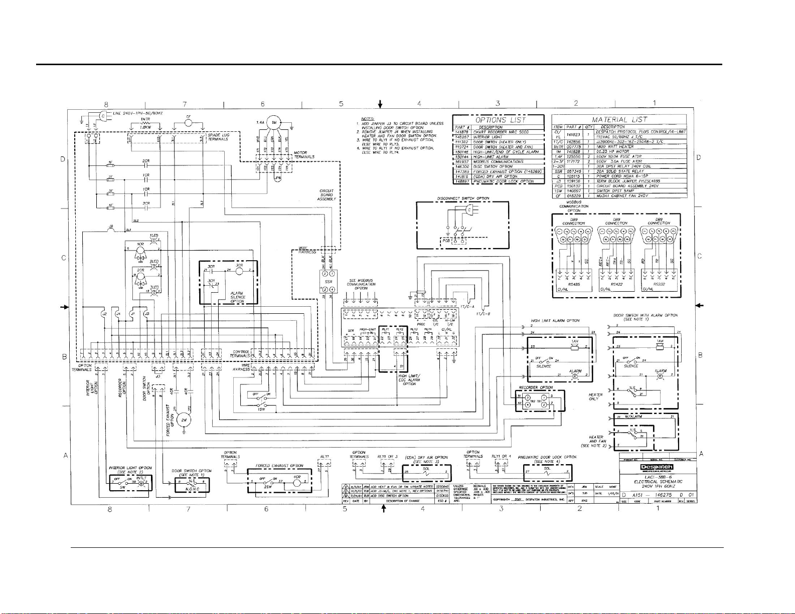
8.2. Electrical Schematics
The following pages contain electrical schematics and data for the LAC1-10-6, LAC138A-6, LAC1-38B-6, LAC1-67-6, LAC2-12-6 and LAC2-18-6 ovens.
All rights reserved. No part of the contents of this manual may be reproduced, copied or transmitted in any form or by any
means including graphic, electronic, or mechanical methods or photocopying, recording, or information storage and
retrieval systems without the written permission of Despatch Industries, unless for purchaser's personal use.
Copyright © 2011 by Despatch Industries.
Page 38

APPENDICES LAC Series Oven Owner’s Manual
Figure 13. LAC1-10-6 (Excerpt from drawing 146271D01).
38 Version 106
All rights reserved. No part of the contents of this manual may be reproduced, copied or transmitted in any form or by any means including graphic, electronic, or mechanical methods
or photocopying, recording, or information storage and retrieval systems without the written permission of Despatch Industries, unless for purchaser's personal use.
Copyright © 2011 by Despatch Industries.
Page 39

LAC Series Oven Owner’s Manual APPENDICES
Figure 14. LAC1-38A-6 (Excerpt from drawing 146273D01).
Version 106 39
All rights reserved. No part of the contents of this manual may be reproduced, copied or transmitted in any form or by any means including graphic, electronic, or mechanical methods
or photocopying, recording, or information storage and retrieval systems without the written permission of Despatch Industries, unless for purchaser's personal use.
Copyright © 2011 by Despatch Industries.
Page 40
APPENDICES LAC Series Oven Owner’s Manual
Figure 15. LAC1-38B-6 (Excerpt from drawing 146275D01).
40 Version 106
All rights reserved. No part of the contents of this manual may be reproduced, copied or transmitted in any form or by any means including graphic, electronic, or mechanical methods
or photocopying, recording, or information storage and retrieval systems without the written permission of Despatch Industries, unless for purchaser's personal use.
Copyright © 2011 by Despatch Industries.
Page 41

LAC Series Oven Owner’s Manual APPENDICES
Figure 16. LAC1-67-6 (Excerpt from drawing 146277D01).
Version 106 41
All rights reserved. No part of the contents of this manual may be reproduced, copied or transmitted in any form or by any means including graphic, electronic, or mechanical methods
or photocopying, recording, or information storage and retrieval systems without the written permission of Despatch Industries, unless for purchaser's personal use.
Copyright © 2011 by Despatch Industries.
Page 42

APPENDICES LAC Series Oven Owner’s Manual
Figure 17. LAC2-12-6 (Excerpt from drawing 146279D01).
42 Version 106
All rights reserved. No part of the contents of this manual may be reproduced, copied or transmitted in any form or by any means including graphic, electronic, or mechanical methods
or photocopying, recording, or information storage and retrieval systems without the written permission of Despatch Industries, unless for purchaser's personal use.
Copyright © 2011 by Despatch Industries.
Page 43

LAC Series Oven Owner’s Manual APPENDICES
Figure 18. LAC2-18-6 (Excerpt from drawing 146281E01).
Version 106 43
All rights reserved. No part of the contents of this manual may be reproduced, copied or transmitted in any form or by any means including graphic, electronic, or mechanical methods
or photocopying, recording, or information storage and retrieval systems without the written permission of Despatch Industries, unless for purchaser's personal use.
Copyright © 2011 by Despatch Industries.
Page 44

LAC Series Oven Owner’s Manual
Despatch
INDUSTRIES
44 Version 106
3rdDraft—
GLOBAL HEADQUARTERS
Despatch Industries
8860 207th Street West
Minneapolis, MN 55044
USA
US toll free: 1-888-337-7282
international/main: 1-952-469-5424
fax: 1-952-469-4513
info@despatch.com
www.despatch.com
SERVICE AND TECHNICAL SUPPORT
service parts: 1-800-473-7373
international service/main: 1-952-469-8230
service fax: 1-952-469-8193
service@despatch.com
© 2010 Despatch Industries. All rights reserved.
Despatch is a registered trademark of Despatch
Industries in the U.S. and other countries.
Ransco is a product line of Despatch Industries.
All rights reserved. No part of the contents of this manual may be reproduced, copied or transmitted in any form or by any
means including graphic, electronic, or mechanical methods or photocopying, recording, or information storage and
retrieval systems without the written permission of Despatch Industries, unless for purchaser's personal use.
Copyright © 2011 by Despatch Industries.
 Loading...