

Page 1

LAC SERIES OVEN
C-184
PN 143365
REVISION H
11/2007
WITH PROTOCOL
PLUS
INSTRUCTION MANUAL
™
Page 2

Notice
Users of this equipment must comply with operating procedures and training of
operation personnel as required by the Occupational Safety and Health Act (OSHA)
of 1970, Section 6 and relevant safety standards, as well as other safety rules and
regulations of state and local governments. Refer to the relevant safety standards in
OSHA and National Fire Protection Association (NFPA), section 86 of 1990.
Caution
Setup and maintenance of the equipment should be performed by qualified
personnel who are experienced in handling all facets of this type of system.
Improper setup and operation of this equipment could cause an explosion that may
result in equipment damage, personal injury or possible death.
Dear Customer,
Thank you for choosing Despatch Industries. We appreciate
the opportunity to work with you and to meet your heat
processing needs. We believe that you have selected the
finest equipment available in the heat processing industry.
At Despatch, our service does not end after the purchase
and delivery of our equipment. For this reason we have
created the Service Products Division within Despatch. The
Service Products Division features our Response Center for
customer service. The Response Center will direct and track
your service call to ensure satisfaction.
Whenever you need service or replacement parts, contact
the Response Center at 1-800-473-7373: FAX 612-781-
5353.
Thank you for choosing Despatch.
Sincerely,
Despatch Industries
Page 3

Page 4
Page 5
i
Page 6

ii
PREFACE
NOTE:
Read the entire
INTRODUCTION and
THEORY OF OPERATION
before installing the oven.
WARNING:
Failure to heed warnings in
this instruction manual and on
the oven could result in
personal injury, property
damage or death.
This manual is your guide to the Despatch oven. It is organized to give you the
information you need quickly and easily.
The INTRODUCTION section provides an overview
of the Despatch oven.
The THEORY OF OPERATION section details the
function and operation of assemblies and
subassemblies on the Despatch oven.
The INSTRUCTIONS section provides directions on
unpacking, installing, operating and maintaining the
Despatch oven.
The APPENDIX section contains special instructions
on air atmosphere and nitrogen atmosphere Burn-In
ovens, a Troubleshooting Table, a list of Accessories
and a Warranty.
The parts are listed in the corner of the attached prints, the electrical items on the
electrical print and the mechanical items on the mechanical prints.
An efficient way to learn about the oven would be to read the manual while working with
the corresponding oven control system. This will give you practical hands-on
experience with information in the manual and the oven.
Before operating the equipment, be sure you understand all of the technical information
contained in this manual. Information skipped, not understood or misunderstood could
create the possibility of operating the equipment in an unsafe manner. This can cause
damage to the oven or personnel or reduce the efficiency of the equipment.
Page 7

iii
Revision B: Corrected Sensor Calibration Page instruction
Revision C: Added definitions and sample profile to Program Page description
Revision D: Correction to Relay Outputs (optional) table
Revision E: Modified per Rev C Protocol Plus software
Revision F: Updated drawings.
Revision G: Revised Protocol Plus times. Updated Despatch address.
Revision H: Updated warranty
Page 8

iv
TABLE OF CONTENTS
INTRODUCTION .......................................................................................................................... 1
Special Features ....................................................................................................................... 1
Specifications ............................................................................................................................ 2
Dimensions ........................................................................................................................... 2
Capacities ............................................................................................................................. 3
Temperature .......................................................................................................................... 3
Power .................................................................................................................................... 4
THEORY OF OPERATION ........................................................................................................... 5
Damper Control ......................................................................................................................... 6
Determining Damper Settings ............................................................................................... 6
Full Closed Position .......................................................................................................... 6
Full Open Position ............................................................................................................. 7
Other Damper Settings ..................................................................................................... 7
INSTRUCTIONS ........................................................................................................................... 8
Unpacking and Inspection ......................................................................................................... 8
Set-up ....................................................................................................................................... 9
Operating ................................................................................................................................ 10
Operating Environment ....................................................................................................... 10
Loading the Oven ................................................................................................................ 10
Pre-Startup Checklist .......................................................................................................... 11
Startup ................................................................................................................................. 12
CONTROL .................................................................................................................................. 13
Theory of Control Operation ................................................................................................... 13
Operating Modes ................................................................................................................. 15
Setup Mode ......................................................................................................................... 15
Fast Start Mode ................................................................................................................... 15
High Limit ............................................................................................................................ 16
Indicators ............................................................................................................................. 16
Displays ............................................................................................................................... 17
Key Functions ..................................................................................................................... 17
Outputs ................................................................................................................................ 18
Communication ................................................................................................................... 19
Optional Software ................................................................................................................ 19
Instructions .............................................................................................................................. 20
Start-Up ............................................................................................................................... 20
Operation ............................................................................................................................ 21
Manual Mode .................................................................................................................. 21
Timer Mode ..................................................................................................................... 22
Profile Mode .................................................................................................................... 23
Auto Start Mode .............................................................................................................. 23
Setup Mode ..................................................................................................................... 24
Instructions for Setup Mode Pages ..................................................................................... 25
Program Page ................................................................................................................. 25
Sample Profile ................................................................................................................. 28
Auto Start Page (optional) ............................................................................................... 29
PID Page ......................................................................................................................... 31
Page 9

v
Control Page ................................................................................................................... 32
Communication Page (optional) ...................................................................................... 33
Real Time Clock Page (optional) .................................................................................... 33
Relay Outputs Page (optional) ........................................................................................ 34
Test Page ........................................................................................................................ 35
Zone Calibration Page .................................................................................................... 36
Sensor Calibration Page ................................................................................................. 38
Enable Page .................................................................................................................... 40
Digital Inputs (optional) ................................................................................................... 41
Error Messages and Alarms ................................................................................................ 42
Quick Reference and Default Values .................................................................................. 43
Technical Specifications ...................................................................................................... 50
MAINTENANCE .......................................................................................................................... 51
Checklist ................................................................................................................................. 51
Tests ....................................................................................................................................... 52
Replacement ........................................................................................................................... 53
Parts .................................................................................................................................... 53
Protocol Plus™ Instrument ..................................................................................................... 54
Heater Unit .............................................................................................................................. 54
Fan Motor ................................................................................................................................ 55
TROUBLESHOOTING ................................................................................................................ 57
DRAWINGS ................................................................................................................................ 59
LAC1-10-5 ............................................................................................................................... 59
LAC1-38A-5 ........................................................................................................................... 61
LAC1-38B-5 ............................................................................................................................ 63
LAC1-67-5 .............................................................................................................................. 65
LAC2-12-5 ............................................................................................................................... 67
LAC2-18-5 ............................................................................................................................... 69
APPENDIX: Temperature Scale Conversion and Optional MRC5000 Setup ............................. 71
Temperature Scale Conversion (C/F) ..................................................................................... 71
Optional MRC5000 Recorder Setup ....................................................................................... 72
Page 10

1
INTRODUCTION
This section provides an overview of the Despatch LAC Series forced air oven. The
LAC Series Ovens have the most effective heat distribution and the fastest processing
time of any lab oven their size. Air is discharged from the left side wall of the oven and
circulates through the chamber.
Special Features
The sturdy construction and three inch insulation of the Despatch LAC Series ovens
contribute to excellent temperature uniformity.
Other special features include the following:
Unique Despatch design to combine higher fan volume of forced recirculated air
with a system of perforated stainless steel walls for the ultimate in temperature
uniformity.
Welded double wall construction and fiberglass insulation to reduce heat loss.
Silicone rubber gaskets further minimize heat leakage.
Rapid response heater.
Scratch-resistant baked enamel exterior and stainless steel interior for easy
cleaning.
Space-saving, stackable design.
Simple pull-open door with "no-hands" closing
Page 11
2
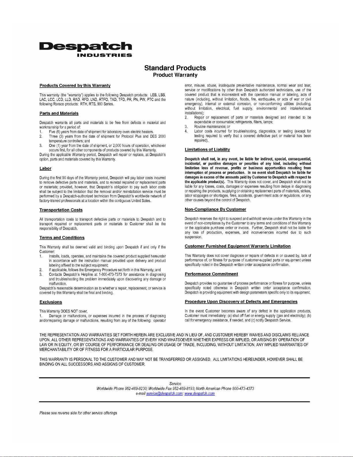
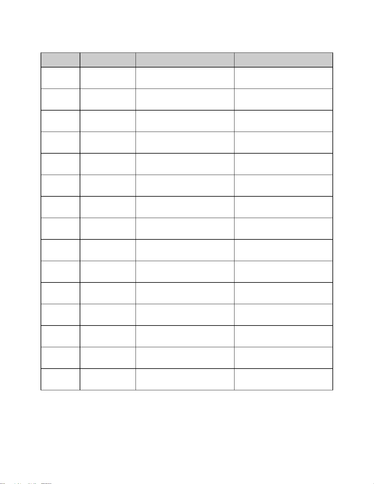
Specifications
LAC
Model
No.
Chamber Size
in (cm)
Capacity
feet
3
(liters)
Overall Size
in (cm)
Max.
Number of
Shelf
Positions
Exhaust
Diameter
Located on Back
of Chamber (in)
W* D H W D
H
1-10
1-38A
1-38B
1-67
2-12
2-18
13.75
(35)
18.75
(48)
18.75
(48)
23.75
(60)
23.75
(60)
35.25
(91)
12
(31)
18
(46)
18
(46)
20
(51)
24
(61)
24
(61)
12
(31)
19
(48)
19
(48)
24
(61)
36
(91)
36
(91)
1
(33)
3.7
(105)
3.7
(105)
6.6
(187)
12
(336)
18
(500)
23
(58)
28
(71)
28
(71)
36
(91)
36
(91)
48
(122)
19
(48)
25
(64)
25
(64)
27
(69)
31
(79)
31
(79)
29.5
(75)
35.5
(90)
35.5
(90)
40.5
(103)
52.5
(133)
52.5
(133)
5
9
9
11
17
17
1
2½
2½
2½
2 - 2½
2 - 2½
Dimensions
* Allow 0.5" clearance on each side for shelf supports.
Page 12
3
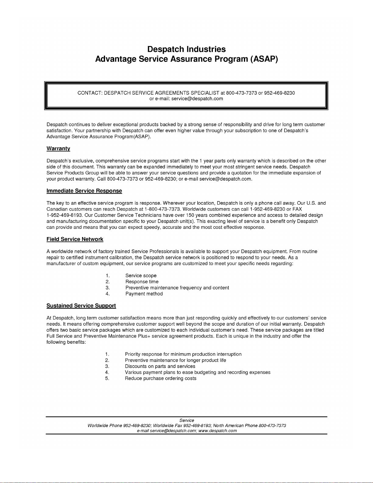
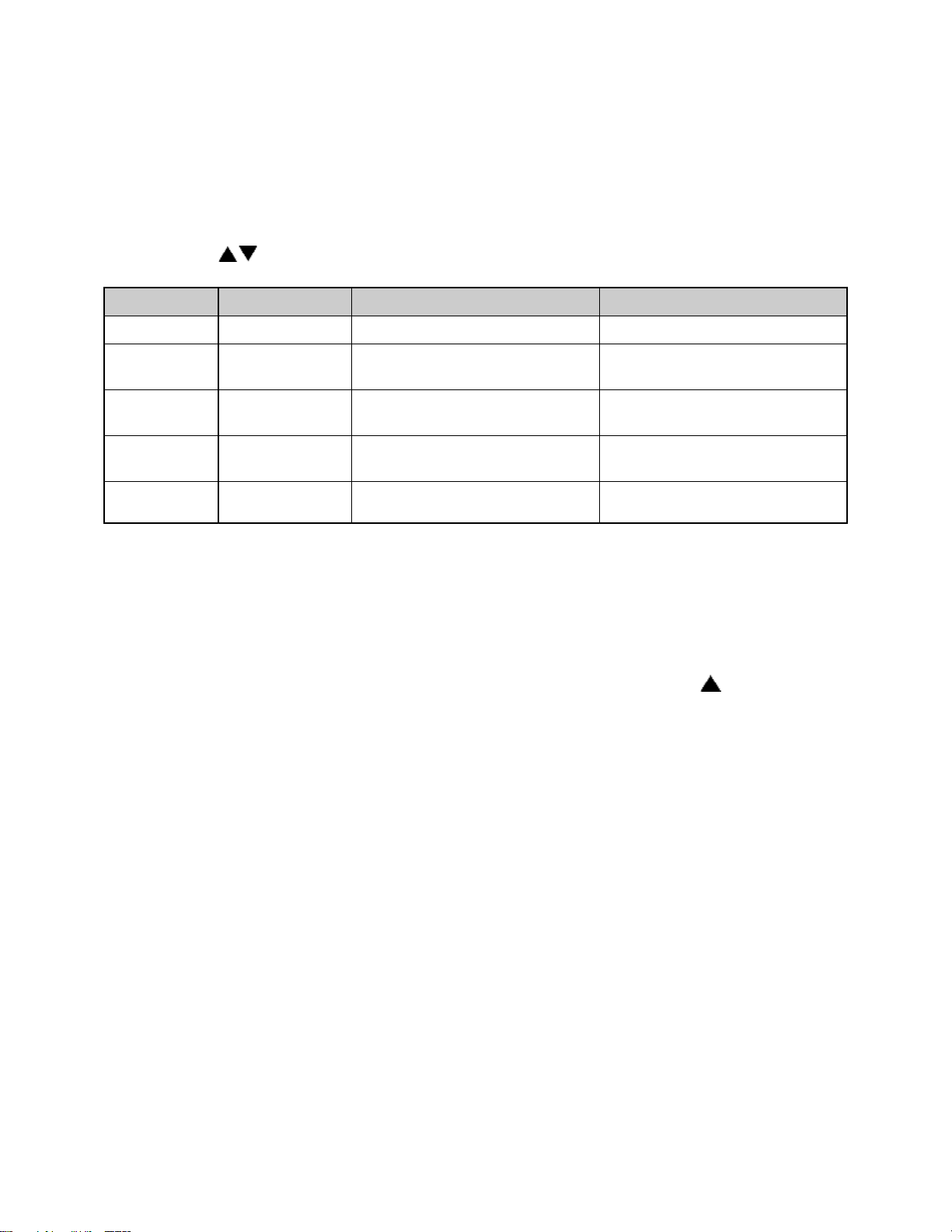
Capacities
LAC Model Number
1-10
1-38 A & B
1-67
2-12
2-18
Maximum Load Lbs
Maximum Shelf Load Lbs
Exhaust CFM
Recirculating Fan CFM
H.P.
Approx. Weight Net Lbs
KG
Shipping Weight Lbs
KG
100
50
Adjustable
to 5
150
1/25
110
50
175
80
125
25
Adjustable
to 12
300
¼
185
84
270
124
150
25
Adjustable
to 12
300
¼
255
115
360
163
175
25
Adjustable
to 30
600
¼ x 2
360
164
480
217
200
25
Adjustable
to 40
600
¼ x 2
450
205
600
271
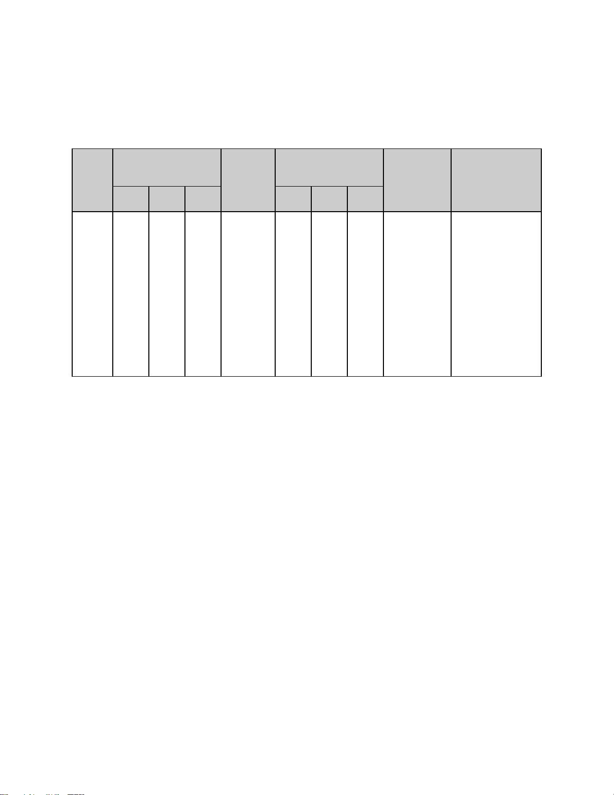
LAC Model Number
1-10
1-38 A
1-38 B
1-67
2-12
2-18
Time to Temperature 40°C - 100°C
(approximate minutes 40°C - 200°C
with no load) 40°C - 260°C
8
25
40
9
32
60
6
22
36
6
20
34
6
19
31
4
17
29
Recovery Time - Door Open 100°C
One Minute (approximate 200°C
minutes with no load) 260°C
1
3
7
1
6
14
1
4
8
1
3
5
1
6
9
1
4
8
Temperature Uniformity at 100°C*
200°C*
260°C*
±1.5°C
±3°C
±4°C
±1°C
±2°C
±2.5°C
Operating Range with 20 C Ambient
40°C - 260°C
Control Stability
±0.5°C per 5°C change in ambient
Repeatability
±0.5°C
Temperature
* Figures are based on actual tests in an empty oven. Uniformity can vary slightly depending on unit and
operating conditions.
Page 13

4
Power
Model
Volts
Amps
Hertz
Phase
Heater
KW
Cord and Plug
LAC 1-10
LAC 1-38A
LAC 1-38B*
LAC 1-67*
LAC 2-12*
LAC 2-18*
120
120
240
240
240
240
10.0
16.5
9.5
12.0
18.5
23.5
50/60
50/60
50/60
50/60
50/60
50/60
1
1
1
1
1
1
1
1.6
1.8
2.4
3.6
4.8
Included, 15 Amp (NEMA 5-15)
Included, 20 Amp (NEMA 5-20)
Included, 15 Amp (NEMA 6-15)
Included, 15 Amp (NEMA 6-15)
None, Hardwired
None, Hardwired
Line voltages may vary in some geographical locations. If your line voltage is much
lower than the oven voltage rating, warm up time will be longer and motors may
overload or run hot. If your line voltage is higher than name plate rating, the motor may
run hot and draw excessive amps.
If the line voltage varies more than 10% from the oven voltage rating, some electrical
components such as relays, temperature controls, etc. may operate erratically.
Power Requirements
* Oven designed for 240 volts (see name plate on oven) will operate satisfactorily on a
minimum of 208 volts, but with a 25% reduction in heater power. If your power
characteristics are lower, contact Despatch Industries. An option is available to
regain the full heater power when operating on 208V.
The LAC 2-12 and LAC 2-18 must be hardwired to the electric supply using 10 AWG or
larger wires suitable for at least 75°C (167°F).
Page 14
5
THEORY OF OPERATION
WARNING:
Do not remove the hat bracket as it distributes exhaust air and protects the exhaust
opening from being completely covered.
This section details the function and operation of assemblies and subassemblies on the
Despatch LAC Series Ovens. These ovens have the most effective heat distribution
system and the fastest processing time of any lab oven its size. They are especially
useful for testing, preheating, sterilizing, drying, aging and curing as well as other
production applications. Horizontal airflow with precision digital control delivers uniform,
fast processing. The overall result is efficient productivity under strenuous conditions.
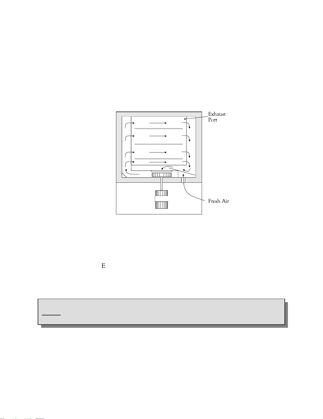
The unique Despatch computerized design, moves forced convected heat through
perforated stainless steel walls. The air is recirculated with a high volume fan.
Despatch LAC Series Ovens employ higher volume fans than any competitive model.
The chamber can be densely loaded without interfering with the process. Air delivery
temperature is within 1 C of the number appearing on the digital display. Fresh air
intake is regulated by a panel-mounted damper control, while the exhaust opening is
fixed. The exhaust port, on the back of the oven, is covered by a hat bracket.
Page 15

6
Damper Control
The oven is equipped with a manually adjustable damper mechanism. The damper
control arm is located on the front panel of the oven. The damper adjustment controls
the fresh air opening which, due to pressurization of the oven chamber, controls the flow
of exhaust. If the damper is in the full open position, the maximum exhaust rate is
achieved. If the damper is in the fully closed position, the minimum exhaust rate is
achieved.
Determining Damper Settings
The optimum setting for the damper depends on several factors. These factors include
ambient environment temperature, load conditions, load distribution, heat up rates, cool
down rates, desired temperature uniformity and most importantly the desired operating
temperature. To consider all of these variables at any one point in time is not practical
and there are engineering tradeoffs that should be considered. Therefore guidelines
should be used to determine the damper setting.
In general, the damper should be set so that the amount of fresh air flowing into and
exhausting from the chamber agrees with the desired operating temperature conditions.
The following outline shows the considerations involved with various damper position
settings.
Full Closed Position
When the damper is in the full closed position, the chamber will be able to achieve the
maximum attainable heat up rates for the chamber. In addition, the chamber will use
the minimum amount of power to operate at the desired temperature. In almost all
cases, the damper should be in the full closed position in order to efficiently operate at
the maximum operating temperature for the chamber.
Page 16

7
Full Open Position
When the damper is in the full open position, the chamber will operate at its minimum
operating temperature.
Friction heat from the air recirculation system builds up in the chamber. This causes
chamber temperature to rise slightly even though the heating system is not turned on.
After the recirculation motor has been on for an extended period of time, the chamber
will reach a thermal equilibrium temperature.
When the damper is not set to the full open position, the chamber has no way to readily
dissipate the heat generated by the friction. With the damper fully open, the thermal
equilibrium temperature is the minimum operating temperature of the chamber.
Other Damper Settings
The damper can be set to several other distinct operating positions. In most cases the
damper setting is influenced by two specific performance factors. The two performance
factors are uniformity and cool down rates.
The uniformity of the chamber is influenced by the inside chamber pressure of the
system. The pressure inside the chamber is dependant on the amount of fresh air
flowing into the chamber. When a large volume of fresh air is flowing into the chamber,
the chamber becomes slightly pressurized and the overall temperature uniformity
improves. The slightly pressurized chamber produces the effect of "pushing" the air to
the corners of the chamber. Typically the corners of the chamber will improve with
respect to temperature distribution while the core of the chamber will maintain excellent
uniformity characteristics regardless of the damper position. Therefore, the
pressurization of the chamber typically is a factor when the chamber is loaded heavily.
The best uniformity results, with respect to the product, are achieved when no more
than two-thirds of any inside chamber dimension are used. The best overall results are
achieved when the product(s) are located in the center of the chamber.
Page 17

8
INSTRUCTIONS
The INSTRUCTIONS section provides directions for unpacking, installation, operation
and maintenance of the LAC Series oven.
Unpacking and Inspection
Remove all packing materials and thoroughly inspect the oven for damage of any kind
that could have occurred during shipment.
See whether the carton and plastic cover sheet inside carton are still in good
condition.
Look at all outside surfaces and corners of the oven for scratches and dents.
Check the oven controls and indicators for normal movement, bent shafts, cracks,
chips or missing parts such as knobs and lenses.
Check the door and latch for smooth operation.
If there is damage that may have occurred during shipment, follow these instructions.
1. Contact the shipper immediately and file a written damage claim.
2. Contact Despatch Industries to report your findings and to order replacement parts
for those that were damaged or missing.
3. Send a copy of your filed damage claims to Despatch.
4. Next, check to make sure you have received all the required materials. Your
shipment should include:
One (1) Despatch oven,
One (1) Instruction manual,
One (1) Warranty card,
Two (2) Shelves
One (1) Package containing four rubber feet
Page 18

9
5. If any of these items are missing from the packaged contents, contact Despatch
WARNING:
All grounding and safety
equipment must be in compliance with applicable codes,
ordinances and accepted
safe practices.
WARNING:
Do not use the oven in a wet
or corrosive, explosive
atmosphere unless the oven
has been specifically
designed for a special
atmosphere.
Industries to have the appropriate materials forwarded to you.
6. Finally, to protect the warranty on your new LAC Series Oven, complete the
warranty card and mail it to Despatch within 15 days after receipt of the equipment.
Set-up
1. Remove adhesive backing sheet from the rubber
feet.
2. Attach rubber feet to the bottom corners of the
oven.
3. Place oven on a bench top or an optional
cabinet base.
The oven must have a minimum of two (2)
inches clearance in the rear to provide proper
ventilation. The oven may be placed next to
another cabinet, or next to another oven, with
three (3) inch clearance (the doors will still
open).
Make sure oven is level and plumb; this will
assure proper heat distribution and operation of
all mechanical components.
4. Identify correct power source indicated on the specification plate.
5. Plug or hardwire oven directly to the electric supply.
Page 19

10
Operating
WARNING:
Do not use oven in wet,
corrosive or explosive
atmospheres unless this
oven is specifically designed
for a special atmosphere.
Users and operators of this oven must comply with
operating procedures and training of operating
personnel as required by the Occupational Safety and
Health Act (OSHA) of 1970, Section 5 and relevant
safety standards, and other safety rules and
regulations of state and local governments. Refer to
the relevant safety standards in OSHA and National
Fire Protection Association (NFPA), Section 86 of 1990.
Operating Environment
The Despatch oven is designed to operate in an industrial setting. Despatch does
recommend the following environmental operating guidelines:
1. The oven is placed on a solid foundation.
2. The oven is not exposed to excessive external vibration.
3. All electrical cabinet covers must remain affixed.
4. Reasonable particulate matter in the atmosphere. Where excessive particulate
matter is present, such as on a construction site or coal processing, Despatch
recommends periodic (usually monthly) cleaning of all electrical compartments.
5. The power supply is within the specifications provided by Despatch. If the facility
power supply is not stable, Despatch recommends a line conditioner.
Loading the Oven
Despatch Industries cannot be responsible for either the process or process
temperature used, or for the quality of the product being processed. It is the
responsibility of the purchaser and operator to see that the product undergoing
processing in a Despatch oven is adequately protected from damage.
Carefully following the instructions in this manual will help the purchaser and operator in
fulfilling that responsibility.
When loading the oven avoid spills of anything onto the heater elements or onto the
floor of the oven. Do not place the load on the oven floor plate. This may cause the
load to heat unevenly and the weight may cause shorting out of the heater elements.
Use the shelves provided.
Page 20

11
The two shelves are designed to be pulled out about half way without tipping for loading
WARNING:
Do not use flammable solvent or flammable material in this oven. Do not process
closed containers of any substance or liquid in this oven because they may explode
under heat.
and unloading. The support capacity of the shelves is listed in the Capacities Table in
the Specifications section in this manual. Do not overload the shelves.
Distribute the workload evenly so that airflow is not restricted. Do not overfill your oven.
The workload should not take up more than two-thirds of any dimension of the inside
cavity.
Pre-Startup Checklist
Know the system. Read this manual carefully. Make use of its instructions and
explanations. Safe, continuous, satisfactory, trouble-free operation depends
primarily on your understanding the system and your willingness to keep all parts
in proper operating condition.
Check line voltage. Voltage must correspond to nameplate requirements of
motors and controls. Refer to the section on power connections in the
INTRODUCTION of this manual.
Fresh air and exhaust. Do not be careless about restrictions in and around the
fresh air and exhaust openings and stacks. Under no condition permit them to
become so filled with dirt that they appreciably reduce the air quantity. The
proper ventilation clearances should be fulfilled at all times. Refer to the Set-up
instructions in this manual.
Ventilation There is an exhaust opening in the rear of the unit that is covered by
a hat bracket. Do not remove the hat bracket as it protects the exhaust opening
from being completely covered.
Helpful hints
For drying ovens, open vent to prevent buildup of moisture.
For sample heating, close the vent when no ventilation is required.
Page 21

12
Startup
For fastest oven heat-up time, close the fresh-air vent. After the desired temperature is
reached, the vent may be adjusted as needed.
1. Start Fan.
a. Open oven door.
b. Press Power switch to the On position. You will hear the recirculating fan
start.
c. Shut oven door.
d. Check that the control display turns on.
2. Operate the temperature control as desired by following the control operation
instructions that follow.
Page 22

13
CONTROL
The special features of the Protocol PlusTM control include:
PID tuning
Ramp/Soak programming of up to 64 segments
Segment looping and profile linking
Built-in manual reset high limit control
Built-in process timer
Dedicated LED display for process temperature
Multi-purpose two-line LCD display with backlight
Auto-tuning
Security access
Process temperature retransmission signal
Digital inputs for remote profile control
Optional relay outputs for events, alarms, or end-of-cycle signal
Optional real-time-clock
Optional RS232/RS422/RS485 MODBUS communications
Theory of Control Operation
The Protocol Plus is a modular microprocessor based digital temperature controller. The
Protocol Plus operates as a dual functioning controller/high limit instrument. The control
portion utilizes a time-proportioning voltage signal to control heating devices with
minimal temperature fluctuations.
The high limit portion protects the product and/or the oven from overheating. If the
product being processed has a critical high temperature limit, the high limit setpoint
should be set to a temperature somewhat below the temperature at which the product
could be damaged. If the product does not have a critical high temperature limit, the
high limit setpoint should be set 5 to 15 degrees higher than the maximum programmed
setpoint at which the oven will operate.
Page 23
14
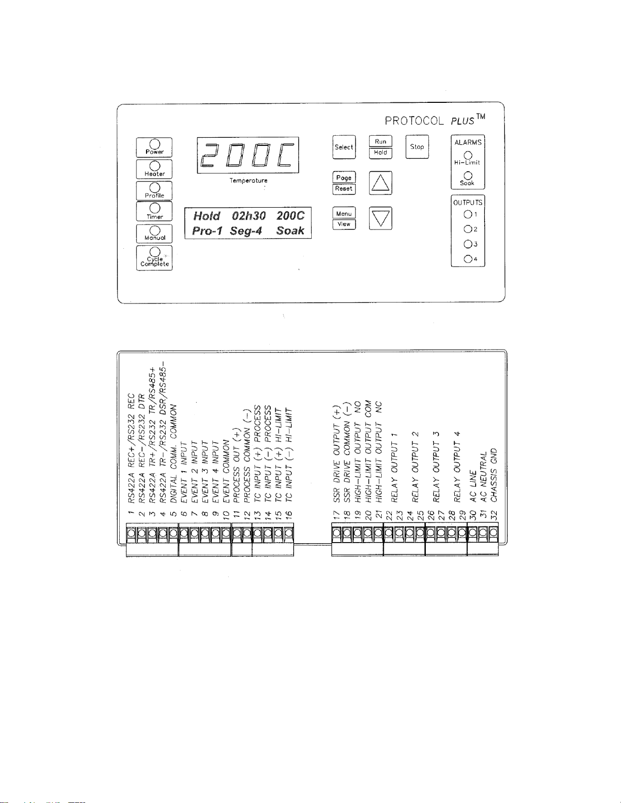
Protocol Plus Faceplate and Wiring Diagram
Page 24

15
Operating Modes
The Protocol Plus control has five modes of operation available:
Stopped Mode: All control and relay outputs are off. Stopped Mode is integrated
into each of the following four modes of operation.
Manual Mode: Control operates as a single setpoint control until Stopped mode is
accessed
Timer Mode: Control operates as a single setpoint control until preset time period
has expired.
Profile Mode: Control operates as a ramp/soak profiling control until the end of
the profile. 8 profiles are available with up to 8 ramp/soak segments
in each profile.
Auto Start Mode (optional): Control may automatically start Manual, Timer, or
Profile mode based on a preset time and day.
Requires the optional real-time clock feature.
The optional event outputs can be utilized during Manual, Timer, or Profile modes.
Setup Mode
The control has a Setup Mode which provides access to control configuration and
programming of profiles. The Setup Mode contains ten separate electronic Pages where
the configuration and programming parameters (Menu items) are found. The Setup
Mode Pages are described in detail elsewhere in this manual.
Fast Start Mode
The Protocol Plus control has the ability to automatically start an operating mode when
power is applied. This feature may be useful if the same mode of operation is used
everyday. The user can turn on the power and the oven will start the desired process
automatically. The Fast Start Mode is controlled by the Power-Up Start parameters on
the Control page (see Setup Mode).
Page 25

16
High Limit
The control has an integrated high limit function which will disable the heater output
when tripped. If the high limit does trip, the relay will need to be manually reset. When
the high limit relay is tripped, the Hi-Limit indicator will be lit. Allow the oven to cool
several degrees (or increase the high limit setpoint) and then press the Reset key. The
indicator will turn off.
The control will not allow the high limit setpoint to be set below the current setpoint
value.
Indicators
The Protocol Plus control has 12 indicating LEDs that provide operational information to
the user.
Power LED: Indicates that power is supplied to the instrument.
Heater LED: Indicates that the heater output is active.
Profile LED: Indicates that the Profile Mode is in operation.
Timer LED: Indicates that the Timer Mode is in operation.
Manual LED: Indicates that the Manual Mode is in operation.
Cycle Complete LED: Indicates that the control is in Stopped mode.
Hi-Limit Alarm LED: Indicates that the high limit relay has tripped (de-energized).
Soak Alarm LED: Indicates that the guaranteed soak deviation is in alarm condition.
Outputs 1 through 4: Indicate that the optional relay outputs are in the ON state.
These outputs may be configured as timed event outputs, process temperature trip
point outputs, alarm outputs, or as an end of cycle relay output. The ON state can be
configured as energized or de-energized.
Page 26

17
Displays
The Protocol Plus control has two displays. A dedicated LED upper display shows the
oven temperature. A two-line LCD lower display provides information on control status
and allows changes to be made to the control settings.
Key Functions
The Protocol Plus control has seven keys that provide operation.
Select key: Press to select mode of operation. In Setup Mode, to select profile
number or relay. In Profile/Run Mode, press simultaneously with the UP key to
advance a segment.
Run/Hold key: Press to activate a mode of operation. If a Profile (or Timer)
Mode is running, pressing the Run/Hold key will place the Profile (or Timer) in
Hold status. A subsequent press will resume the Profile (Timer).
Stop key: Press to stop any mode of operation.
Page/Reset key: While in Setup Mode, press to access different Pages of
configuration, Press this key to silence an alarm if the instrument alarm sounds
during operation. In an operating mode, if an alarm or error condition occurs,
press this key to return the instrument to normal operation once the condition is
cleared.
Menu/View key: While running any operating mode, pressing this key will
display the high limit setpoint. While in Setup Mode, pressing this key will provide
access to each Menu parameter.
keys: Press these keys to adjust parameter settings. In Profile/Stopped
Mode, press to select profile to run. In Profile/Run Mode, press key
simultaneously with the Select key to force the program to advance one
segment.
Page 27

18
Outputs
The Protocol Plus control has seven different outputs available.
Heating output: The control output is a DC voltage open-collector output which
is time-proportioned and designed to control a heat control device such as a solid
state relay.
High limit: The high limit output is a form C relay which is energized under
normal operating conditions. If the control senses a temperature higher than the
high limit setpoint, or if there is a sensor error, the high limit relay will de-energize
until the condition is cleared and the Reset key is pressed. When the high limit
relay is de-energized, the heater is disabled.
Retransmission: The retransmission output is a DC 0 to 5 volt or 4 to 20 ma
(DC) signal that is proportional to the process temperature. The signal can be an
input to other devices such as a chart recorder.
Relay (four optional outputs): The four form A dry contact relay outputs can be
configured to function as alarms, events, or end of cycle. These outputs can be
utilized in Manual, Timer, or Profile Mode.
Layout for Optional Components
Page 28

19
Relay (Continued)
Use the Relay Card Optional Ay p/n 144562 to add relays to the standard controller.
Each relay card contains two relays (maximum of two cards Ay’s allowed).
Communication
The Protocol Plus control has optional MODBUS communication available which can
communicate via RS232, RS422, or RS485 to a computer. See communications option
assembly p/n 141877 for board and cable assembly. Please refer to the MODBUS
communications manual which comes with this option.
Optional Software
The Protocol Manager program allows the operator to start/stop multiple ovens (32
maximum) from a personal computer. A data log can also be used to record process
information (p.n. 140008).
Page 29

20
Instructions
Start-Up
These instructions are provided as a quick reference for operating the Protocol Plus
control. If the Profile Mode is to be used, or the configuration of the control needs to be
changed, please refer to the Setup Mode instructions before operating the control. For
more detailed operating instructions refer to the Operation instructions for the mode you
wish to use.
Upon initial power-up the control is in Manual/Stopped Mode (unless the Autostart or
Fast Start Modes are active). To activate any operating mode from Stopped Mode,
press the Select key until the desired mode is displayed, then press the Run key. If the
proper Profile number is not displayed when the Profile Mode is accessed, press the
or keys until the desired Profile number is displayed, then press the Run key. If no
profile numbers can be displayed (display only reads NONE) then no profiles are
currently programmed (see Setup Mode).
The temperature setpoint can be adjusted while Manual or Timer Mode is running by
pressing the UP or DOWN key.
To momentarily hold the Timer or Profile Mode, press the Hold key. To continue the
Timer or Profile Mode, press the Run key.
To return to Stopped Mode at any time, press the Stop key and the cycle complete LED
will illuminate.
Note that the control can be configured to automatically activate Manual, Timer or
Profile Mode when power is applied (power switch turned on). See Control Page in the
Setup Mode to utilize the Fast Start mode.
Page 30

21
Operation
Manual Mode
Press the Select key until Manual is displayed (note you can press the Run key at any
time to activate Manual Mode).
1. Press the Menu key to display the Process Temperature Setpoint (setpt). You
can change the Setpoint with the keys.
Note: If the SPChange parameter on the Enable page in Setup Mode has been
set to DISABLED, it must be changed to ENABLED before any changes to the
process temperature and high limit setpoints can be made.
2. Press the Menu key a second time to display current high limit setpoint (Hi-Lim
SP). The value can be adjusted by pressing the keys. If Band is displayed,
the high limit band feature is activated (see Control page) and the high limit can
not be adjusted.
3. (optional feature) Press the Menu key a third time to display Event1. Press the
key to turn on the event or to turn off the event. Repeat for all events which
are enabled (up to 4).
4. To start Manual Mode, press the Run key.
The display will change from Stop to Run. To return to Stopped Mode, press the Stop
key. While in operation, the process setpoint can be adjusted by using the keys to
change the value while the mode is running. Pressing the Menu key will display the
High Limit Setpoint (HLSP) setting.
If changes to the high limit setpoint or event output configuration are needed, they must
be done from the stopped mode.
Page 31

22
Timer Mode
1. Press the Select key until Timer is displayed (note you can press the Run key at
any time to activate Timer Mode).
2. Press the Menu key to display the Process Temperature Setpoint (Setpt). You
can change the Setpoint with the keys.
Note that if the SPChange parameter on the Enable page in Setup Mode has
been set to DISABLED, it must be changed to ENABLED before any changes to
the process temperature and high limit setpoints can be made.
3. Press the Menu key a second time to display current high limit setpoint (Hi-lim
SP). The value can be adjusted by pressing the keys. If Band is displayed,
the high limit band feature is activated (see Control page) and the high limit can
not be adjusted.
4. Press the Menu key a third time to display Time Set. You can change the time
setting with the keys.
5. (optional feature) Press the Menu key a fourth time to display Event1. Press the
key to turn on the event or to turn off the event. Repeat for all events which
are enabled (up to 4).
6. Press the Menu key a fifth time to display the current guaranteed soak band
(TmrGuarSoak) value. If the process temperature deviates from the setpoint by
more than this value, the timer is placed in a hold condition. The timer continues
when the process temperature falls within range. Reference the Quick
Reference and Default Values section for available settings.
7. To start Timer Mode, press the Run key.
The display will change from Stop to Run and the time remaining will be
displayed. To return to Stopped Mode, press the Stop key. While in operation,
the process setpoint can be adjusted by using the keys to change the value
while the mode is running. Pressing the Menu key will display the High Limit
Setpoint.
Pressing the Run/Hold key while the Timer Mode is in operation will put the control in
Hold status. The Timer LED will flash to indicate the held status. Press the Run/Hold
key again to continue timing. The Timer LED will return to lit status.
Page 32

23
Profile Mode
1. Press the Select key until Profile is displayed. “None” may be displayed if a
profile has not been selected or no profiles entered.
2. Press the key to display the desired profile to run.
3. To start Profile Mode, press the Run key.
The display will change from Stop to Run and the segment time remaining,
Temperature Setpoint, Profile #, along with the current segment number, will be
displayed. To return to Stopped Mode, press the Stop key.
Pressing the Run/Hold key while the Profile Mode is in operation will put the control in
Hold status. Press the Run/Hold key again to continue the mode. The Profile LED will
flash to indicate the hold status.
To advance to the next segment while running a profile, press the Select and UP arrow
keys at the same time.
Note that ramping down too fast may cause the high limit relay to trip unexpectedly if
the high limit band feature is used. This can be avoided by using a separate cooling
profile that does not utilized the high limit band and then jumping to that profile to
perform rapid cooling.
Auto Start Mode
The Auto Start Mode allows the control to start Manual, Timer, or Profile mode
automatically at a preset time and day. See the Auto Start Page in Setup Mode for the
time, day, and operating mode settings. The Auto Start Mode requires the optional Real
Time Clock feature for operation.
To activate the Auto Start Mode, the control must first be in Stopped Mode.
1. Press the Select key until Auto Start is displayed.
2. Press the Menu key.
3. Press the keys to activate or deactivate the Auto Start feature.
Note that once you activate Auto Start, you can continue to use all operating modes as
normal. If an operating mode is running at the time of a preset Auto Start function, and
Auto Start is activated, the existing operating mode will override the auto Start function
and the Auto Start will not turn on.
To use the Auto Start for the next day, the auto start must show in the LCD display that
it is active.
Page 33

24
Setup Mode
Configuration of the control and programming of the ramp/soak profiles must be done in
the Setup Mode. To access Setup Mode, the control must first be in Stopped Mode.
1. Press the Select key until Setup is displayed.
2. Press the Page key and Security will be displayed.
3. Press the Menu key and Password will also be displayed. Use the keys to
enter the proper password.
4. Once the proper password is displayed, press the Page key twice to enter the
Setup Mode.
To exit Setup Mode, press and hold the Page key for three seconds.
The control has two levels of password-protected security. Level one provides access
only to those menu pages that are enabled on the Enable page. Level two provides
access to all menu pages, including the Enable page. The default security password
values are 1 for level one and 2 for level two.
If an improper password has been entered, the control will remain at the Security
display. To enter the proper password, press the Menu key. To exit Setup Mode, press
and hold the Page key for three seconds.
Mapping of the Setup Mode is provided in the following sections. To access each
parameter Page, which are described in detail in the following sections, press the Page
key until the desired page heading is displayed. Press the Menu key to access each
Menu parameter. Press the keys to change Menu parameter settings.
Refer to the Quick Reference and Default Values section for available settings for each
Menu parameter.
Press the Page key to continue with each Page, or press and hold the Page key for
three seconds to exit Setup Mode.
Page 34

25
Instructions for Setup Mode Pages
Program Page
Programming of the profiles is provided on the Program Page. Eight profiles are
available with up to eight ramp and soak segments per profile.
If the optional relay outputs are installed, they must be configured as alarms or events
on the Relay Outputs Page before they can be utilized. If configured as event outputs,
these relays can be used as time or temperature events.
When entering the Program Page, press the Select key to select the profile you wish to
enter/edit, then press the Menu key. The first parameter (Profile #, Segment 1, Ramp
Time) will display. Adjust the time value with the keys. Once the proper value is
displayed, press the Menu key to continue. Continue with the Menu key to adjust/view
each parameter.
If the ramp time value of the current segment is left at 0:00, the next press of the Menu
key will advance the control to the High Limit Setpoint parameter for that profile.
Continue entering / verifying all parameters until you get to the last parameter
(Guaranteed Soak Band). Once all parameters have been properly entered, press the
Page key to return to the top of the Profile Page. You can press the Select key to
enter/edit another profile, press the Page key to access another page, or press and hold
the Page key to exit Setup mode.
While editing any profile, pressing the Select key will advance the control to the time
value for the next segment, until the last segment has been reached. This allows faster
editing of the profile rather than pressing the Menu key to advance past each
parameter.
To run a profile indefinitely, link the profile to itself.
Page 35
26
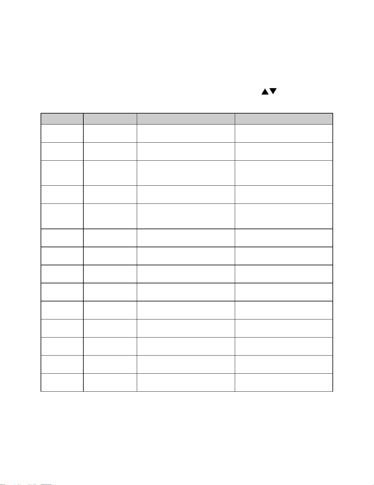
Menu Item
Display
Description
Ramp Time Seg 1
Pro-1 Seg-1 Ramp Time
Ramp time for segment 1 of profile
Event 1 Set Value*
Pro-1 Seg-1 Ramp Event 1
Event 1 setting for segment 1 ramp of profile
Event 2 Set Value*
Pro-1 Seg-1 Ramp Event 2
Event 2 setting for segment 1 ramp of profile
Event 3 Set Value*
Pro-1 Seg-1 Ramp Event 3
Event 3 setting for segment 1 ramp of profile
Event 4 Set Value*
Pro-1 Seg-1 Ramp Event 4
Event 4 setting for segment 1 ramp of profile
Soak Temp Seg 1
Pro-1 Seg 1 Soak Temp
Soak temperature for segment 1 of profile
Soak Time Seg 1
Pro-1 Seg 1 Soak Time
Soak time for segment 1 of profile
Event 1 Set Value*
Pro-1 Seg-1 Soak Event 1
Event 1 setting for segment 1 soak of profile
Event 2 Set Value*
Pro-1 Seg-1 Soak Event 2
Event 2 setting for segment 1 soak of profile
Event 3 Set Value*
Pro-1 Seg-1 Soak Event 3
Event 3 setting for segment 1 soak of profile
Event 4 Set Value*
Pro-1 Seg-1 Soak Event 4
Event 4 setting for segment 1 soak of profile
(repeat for segments 2-8, until ramp or soak time = 00:00)
High Limit Setpoint
Pro-1 Hi-Lim SP
High limit setpoint for profile**
Loop From
Pro-1 Loop From Seq
To start a loop action in a profile
Loop To
Pro-1 Loop To Seq
To end a loop action in a profile
Loop Count
Pro-1 Loop Number
Number of times to execute loop
Profile Link
Pro-1 Link To Pro
To jump from this profile to another
Guaranteed Soak
Pro-1 Guar Band
Guaranteed soak band for profile
See the definitions on the following pages for parameter ranges.
* only available if optional relay outputs are installed (repeat all for profiles 2-8)
** Set to Band to use the high limit band feature
Page 36

27
Profile #
There are eight profiles available.
Segment#
Recipe segments 1 through 8 may be programmed, each with its own
set of events, ramp and soak times, and soak temperature.
Ramp Time
The time required to ramp from one setpoint up to another setpoint.
Values between 0 and 99:59 are allowable. In the Protocol Plus
controller, the profile ramp and soak times are stored without units.
Units are set as either hours and minutes (HH:MM) or minutes and
seconds (MM:SS). The setpoint will automatically increment from the
actual temperature to the soak temperature.
EV1 through 4
From 1 to 4 events may be programmed into the ramp time portion of
each segment here. These typically involve actuating/disabling relays
to close/open valves or perform other relay-controlled functions.
NOTE: These will only actuate when the controller has the relay cards
installed and programmed for an event.
Soak Temp.
The temperature setpoint of a particular segment is entered here; it
can range from -18 to 540 degrees C (0 to 1000 degrees F).
Soak Time
The duration of soak is entered here; the value can range from 0 to
99:59.
EV1 through 4
From 1 to 4 events may be programmed into the soak portion of each
segment here. These typically involve actuating/disabling relays to
close/open valves or perform other relay-controlled functions. NOTE:
These will only actuate when the controller has the relay cards
installed and programmed for an event.
Hi Limit SP
The high limit setpoint may be entered here; if the temperature
exceeds this value, the hi-limit will alarm and shut off the heater.
Loop From
Values are No, Seq-1 to Seq-8.
Loop To
Values are No, Seq-1 to Seq-8.
Loop Number
Values are 0 - 99.
These values enable the operator to jump from a certain step to
another step of the recipe a preset number of times.
Profile Link
Values are STOP/HOLD/1 - 8. When the profile ends, the profile can
turn the heater off, hold the temperature setpoint at the end of the
profile, or jump to another specified profile.
Guaranteed
Soak Band
If the process temperature deviates from the setpoint by more than
this value, the soak timer is placed in a hold condition. The timer
continues when the process temperature falls within range.
Page 37
28
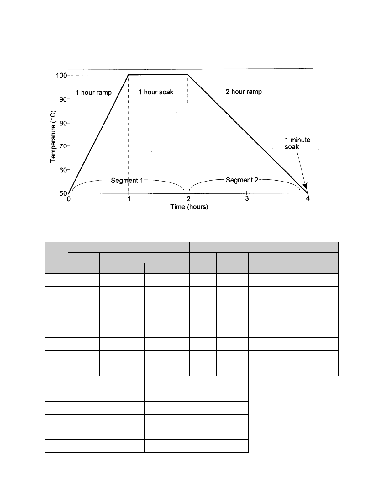
Sample Profile
Seg-
ment
Ramp
Soak
Time
Events
Temp-
erature
Time
Events
1 2 3 4 1 2 3
4
1
01h00
100
01h00
2
02h00
50
00h01
3
00h00
4 5 6 7 8
High Limit Setpoint
115 Loop From Seq
No
Loop To Seq
No Loop Number
0
Link To Pro
No Guar Soak Band
10
29
Programming Table
Profile Number____1______ Profile Name__________
Page 38

Auto Start Page (optional)
If the optional real time clock has been installed, the Auto Start Page can be configured
to automatically start Manual, Timer or Profile Mode at a specified time and day. Note
that if Auto Start Enable is set to Yes in the Setup Mode, the Auto Start feature is not
turned on - it is available to the operator to be activated in Stopped Mode.
To configure the Auto Start feature:
1. Access the Setup Mode.
2. Press the Page key until Auto Start is displayed.
3. Press the Menu key. If there is no change in the display, the controller may not
have the realtime clock option.
4. Set Auto Start Enable to Yes.
5. Using the Menu key, scroll through the options available and use the keys
to set the mode desired for each day of the week. You may select from Manual,
Timer, or Profile 1 through 8.
6. When the mode is set press the Menu key.
7. Enter the time of day you wish the mode to activate.
8. Continue through the rest of the week by pressing the Menu key, or press the
Page key when done.
One Auto Start mode can be set for each day of the week. Exit the Setup mode by
pressing and holding the Page key for three seconds. Press the Select key until Auto
Start is displayed. Make sure the correct time and day is displayed. If not proper, set it
to the correct time on the Real Time Clock Page in the Setup mode. Press the Run key
to activate Auto Start. The display will change from Stop to Active. When the preset time
and day occurs, the appropriate operating mode will start. You can de-activate Auto
Start by pressing the Select key until Auto Start is displayed, then pressing the Stop
key.
Note that once you activate Auto Start, you can continue to use all operating modes as
normal. If an operating mode is running at the time of a preset Auto Start function, and
Auto Start is activated, the existing operating mode will override the Auto Start function
and the Auto Start will not turn on.
Page 39
30
Menu Item
Display
Description
Range
Enable
Autostart
Auto Start Enable
Enable (yes) or disable (no) the
Autostart function
No, Yes
Sunday
mode
Auto Start Sun
Mode
Set mode on Sunday to activate
Off, Manual, Timer, Pro-1 to Pro-8
Sunday
time
Auto Start Sun
Time
Set time on Sunday for mode to
activate
00:00 to 23:59
Monday
mode
Auto Start Mon
Mode
Set mode on Monday to activate
Off, Manual, Timer, Pro-1 to Pro-8
Monday
time
Auto Start Mon
Time
Set time on Monday for mode to
activate
00:00 to 23:59
Tuesday
mode
Auto Start Tue
Mode
Set mode on Tuesday to activate
Off, Manual, Timer, Pro-1 to Pro-8
Tuesday
time
Auto Start Tue
Time
Set time on Tuesday for mode to
activate
00:00 to 23:59
Wednesday
mode
Auto Start Wed
Mode
Set mode on Wednesday to
activate
Off, Manual, Timer, Pro-1 to Pro-8
Wednesday
time
Auto Start Wed
Time
Set time on Wednesday for mode
to activate
00:00 to 23:59
Thursday
mode
Auto Start Thu
Mode
Set mode on Thursday to activate
Off, Manual, Timer, Pro-1 to Pro-8
Thursday
time
Auto Start Thu
Time
Set time on Thursday for mode to
activate
00:00 to 23:59
Friday
mode
Auto Start Fri
Mode
Set mode on Friday to activate
Off, Manual, Timer, Pro-1 to Pro-8
Friday time
Auto Start Fri
Time
Set time on Friday for mode to
activate
00:00 to 23:59
Saturday
mode
Auto Start Sat
Mode
Set mode on Saturday to activate
Off, Manual, Timer, Pro-1 to Pro-8
Saturday
time
Auto Start Sat
Time
Set time on Saturday for mode to
activate
00:00 to 23:59
Page 40
31
PID Page
Menu Item
Display
Description
Range
Display units
PID Temp Unit
Set display units to °C or °F
°C or °F
Proportional
band
PID Prop Band
Set proportional band for tuning
1 to 56°C (1 to 100°F)
Integral reset
PID
Reset/Rep/Min
Set integral reset for tuning
0 to 100 seconds/repeat
Derivative
Rate
PID Rate In Sec
Set derivative rate for tuning
0 to 500 seconds
AutoTune
PID AutoTune
Enable auto tuning function
Disable, Enable
The PID Page contains parameters which control the response to the setpoint and
process variable input. To access the PID Page, enter the Setup Mode (see Page 11).
Press the Page key until PID is displayed. Press the Menu key. Each parameter can be
changed by pressing the Menu key until the desired parameter is displayed, and then
pressing the keys to change the value.
The AutoTune parameter disables or enables the AutoTune function. To utilize
AutoTuning:
1. Access the Setup Mode.
2. Press the Page key until the display reads AutoTune. Press the key to enable
the AutoTune.
3. Press the Page key for three seconds to exit Setup Mode.
4. Cycle power to the instrument.
5. Set Manual Mode to run. The display will alternately display AutoTune and
Manual.
If the Manual Mode setpoint is less than 50 degrees higher than the actual process
temperature, the AutoTune function will create an error condition. This can be cleared
by either cooling off the process temperature or increasing the setpoint until there is
more than 50 degrees between them. Once the AutoTune function is allowed to
complete tuning, the AutoTune parameter will disable by itself.
If you wish to cancel the AutoTune function, press the STOP key, access the PID page
in Setup Mode, and set the AutoTune parameter to Disable.
Page 41
32
Control Page
Menu Item
Display
Description
Range
Cycle Time
Control Cycle
Time Sec
Set cycle time in seconds for
control output
1 to 60 seconds
High limit
setpoint
Control Hi-Lim
SP***
Maximum value for all high limit
setpoints
MinHiLimSP - MaxHiLimSP*
High limit
band
Control Hi-Lim
Band
If=0, high limit setpoint= Control
Hi-Lim SP If>0, high limit
setpoint= Control SP* + Band
Off, 3°C to 11°C (5°F to 20°F)
Power fail
recovery
Control PwrFRec
Controls response to loss of
power
Stop, Restart, Hold, Resume
Recovery
time limit
Control
PFRTime****
Control aborts to Stopped mode if
power is lost for time period
longer then set value
00m00s to 99m59s
Powerup
start enable
ControlPwrUpStrt
Allows mode to automatically
start when power is first applied
Disable, Enable
Powerup
Start Mode
Control StrtMode
Operating mode for powerup start
Off, Manual, Timer, Pro-1 to Pro-8
Hysteresis
Control
Hysteresis
Hysteresis for all alarms and
temperature events
1°C to 56°C (1°F to 100°F)
Process out
low
Control
RetOutLo
Process value for retransmit
output = 1VDC
-73°C to 760°C (-100°F to 1400°F)
Process out
high
Control RetOutHi
Process value for retransmit
output = 5VDC
-73°C to 760°C (-100°F to 1400°F)
Time scale
Control
TimeScale
Time scale setting for program
and timer mode**
hh:mm or mm:ss
Key press
beep
Control KeyBeep
Internal beeper sounds when key
is pressed
On or Off
End of cycle
beep
Control
EOCBeep
Internal beeper sounds at end of
cycle
On or Off
Alarm beep
Control
AlarmBeep
Internal beeper sounds for alarms
On or Off
The Control Page contains various parameters which control miscellaneous functions.
To access the Control Page, enter the Setup Mode. Press the Page key until Control is
displayed. Press the Menu key. Each parameter can be changed by pressing the Menu
key until the desired parameter is displayed, and then pressing the keys to change
the value.
* includes ramping setpoints during profiles and controlled ramps
** power fail recovery time limit is always MM:SS regardless of time scale setting
*** high limit setpoint is a read-only item which is calculated on Enable page
**** requires real-time-clock feature
Page 42

33
Communication Page (optional)
Menu Item
Display
Description
Range
Address
Communication CommAddr
Sets address node for
control
1 to 255
Mode
Communication Mode
Turns on/off
communications
OFF, Modbus
Baud Rate
Communication BaudRate
Sets interface speed
2400, 4800, 9600, 19.2K,
38.4K
Parity
Communication Parity
Sets parity for interface
None, Odd, Even
Menu Item
Display
Description
Range
Day of the
week
Clock Day
Setting for current day of the week
Sun, Mon, Tue, Wed, Thu, Fri, Sat
Time of
day
Clock HH:MM
Setting for current time of the day
00:00 to 23:59
Reset
clock
Clock UP to
Reset CLK*
Press the key to set the clock
to entered values
Ready, Done
The Communication Page contains parameters for the communications feature. To
access the Communications Page, enter the Setup Mode (see description earlier in this
manual). Press the Page key until Communication is displayed. Press the Menu key.
Each parameter can be changed by pressing the Menu key until the desired parameter
is displayed, and then pressing the keys to change the value.
Real Time Clock Page (optional)
The Real Time Clock Page allows the control to be configured to have an operating
mode begin automatically at a specific time on a specific day of the week. The real time
clock feature is required for using the Power Failure Recovery mode Time Limit feature
(see Control Page). The real-time-clock is a seven day, 24 hour clock with battery
backup.
To access the Real Time Clock Page, enter the Setup Mode. Press the Page key until
Clock is displayed. Press the Menu key. (If there is no change in the display, the
controller may not have the realtime clock option.) Each parameter can be changed by
pressing the Menu key until the desired parameter is displayed, and then pressing the
keys to change the value.
* If the key is not pressed, the clock values will retain their original values. The
display will change to Done if the clock is reset
Page 43

34
Relay Outputs Page (optional)
Menu Item
Display
Description
Range
Type of relay
Relay 1
RelayType
Set function of relay
Off, Alarm, Cycl, Ev1 to Ev4
Action of relay
Relay 1
RelayAction
Set coil and contact state of
relay
NDE, NE, NDEL, NEL*****
Type of
alarm*
Relay 1
AlarmType
Set alarm type for relay
High, Low, Plus, Minus, Band
Alarm
setpoint*
Relay 1 AlmHi/Lo
SP
Setpoint for alarm
-73°C to 760°C (-100°F to
1400°F)
Alarm
deviation*
Relay 1
AlmDevBand
Deviation band for alarm
1 to 56°C (1 to 100°F)
Inhibit alarm*
Relay 1
ALMInhibit
Inhibits alarm until "safe"
condition is reached
En or Dis
Type of
event**
Relay 1
EventType
Set event type for relay
Time or Temp
Event
setpoint***
Relay 1 Event SP
Setpoint for temperature event
SPLoLim to SPUpLim****
The Relay Outputs Page configures the four alarm/event outputs. Each output has a
dedicated indicator light and can be configured as a temperature alarm, profile event, or
end of cycle output. Temperature alarms can be of type process high, process low,
deviation high, deviation low, or deviation band.
To access the Relay Page, enter the Setup Mode (see description earlier in this
manual). Press the Page key until Relay is displayed. Press the Select key until the
desired relay output is selected. Press the Menu key. Each parameter can be changed
by pressing the Menu key until the desired parameter is displayed, and then pressing
the keys to change the value. To configure a specific relay, press the Select key
until the desired relay appears.
NOTE: If Relay 0 appears, then no relays are installed (see relay kit assembly p.n.
144562).
(repeat for relay outputs 2-4, if available)
* appears only for alarm types
** appears only for time or temperature event types
*** appears only for temperature event types
Turning on the Alarm Inhibit function disables the alarm output on power up until the
process temperature has reached a non-alarming condition ("safe").
If the relay output has been configured as latching, the RESET key must be pressed to
return the output to the non-alarm state once the alarm condition has cleared.
Page 44

35
Test Page
Menu Item
Display
Description
Range
Heater
output
Test HeatOut
Activate SSR output 100%
On
High limit
relay
Test HiLimOut
Activate high limit alarm
(de-energize relay)
On
Relay 1
output
Test Rly1 Out
Energize relay output 1
On
Relay 2
output
Test Rly2 Out
Energize relay output 2
On
Relay 3
output
Test Rly3 Out
Energize relay output 3
On
Relay 4
output
Test Rly4 Out
Energize relay output 4
On
HiLim
Sensor
Test HL Temp
(push and hold up)
Displays sensor reading*
The Test Page contains parameters which allow manual control of the heat control and
optional relay outputs and should be used only for testing the functionality of the control
instrument. Do not operate the oven for processes using the Test Page.
To access the Test Page, enter the Setup Mode (see description earlier in this manual).
Press the Page key until Test is displayed. Press the Menu key. Each parameter can be
changed by pressing the Menu key until the desired parameter is displayed, and then
pressing the keys to change the value.
*Push key to refresh display
When the Test Page is entered, all outputs are automatically set to off. When exiting
the Test Page, all outputs will return to their previous condition regardless of the Test
Page settings.
Page 45

36
Zone Calibration Page
Menu Item
Display
Description
Range
Zone 1
actual
Zone Cal
Zone1Act
Point at which Zone 1 is set (center
of chamber)
-73°C to 760°C (-100°F to 1400°F)
Zone1
displayed
Zone Cal
Zone1Dis
Desired displayed value for Zone 1
setting
-73°C to 760°C (-100°F to 1400°F)
Zone 2
actual
Zone Cal
Zone2Act
Point at which Zone 2 is set (center
of chamber)
-73°C to 760°C (-100°F to 1400°F)
Zone2
displayed
Zone Cal
Zone2Dis
Desired displayed value for Zone 2
setting
-73°C to 760°C (-100°F to 1400°F)
Factory
calibration*
Zone Cal
FactCal
Restores the factory calibration
values
Ready or Done (push- key)
The Zone Calibration Page allows adjustment of the displayed temperature versus the
actual temperature measured by the control thermocouple. This may be desirable in
certain conditions where the center of the oven chamber is not the same temperature as
the control thermocouple. This may occur when the oven is not allowed to soak at a
constant temperature for long periods of time, or the oven is being used at high
temperature.
There is also a Factory Calibration Recovery which will restore the factory calibration
values when the control was first shipped by the manufacturer. This may be helpful if
the calibration has been lost and a calibration instrument is not readily available. To use
the Factory Calibration Recovery feature only, bypass the Zone 1 and Zone 2
calibration parameters by pressing the Menu key.
To access the Zone Calibration Page, enter the Setup Mode (see description earlier in
this manual). Press the Page key until Zone Cal is displayed. Press the Menu key. Each
parameter can be changed by pressing the Menu key until the desired parameter is
displayed, and then pressing the keys to change the value.
*Only use when no calibration instrument is available, push key to restore factory
values.
Press the Page key to exit the Zone Calibration Page.
Two points of display calibration (temperature offset) are available. The Zone 1 Actual
and Zone 2 Actual parameters are the two temperature points where the offset is to take
effect. These values are adjustable. The Zone 1 and Zone 2 Displayed parameters are
the values the user wishes to have displayed at the Actual temperatures, and are also
adjustable.
Page 46

37
As an example, the control is displaying 400°F with the setpoint being 400°F, but the
center of the oven chamber is actually 395°F. This can occur due to oven wall losses
and product loading variations. The operator may change the zone calibration so that
the center of the oven is 400°F when the display reads 400°F. In this case operate the
oven in manual mode with a setpoint of 400°F. Record the center of the chamber (as
measured with an independent sensor). Access the Zone Calibration Page and enter
this measured value as the Zone 2 Actual value, with 400° as the Zone 2 Displayed
value.
Zone 1 can be adjusted using the same method at a lower temperature. The instrument
will then create a linear offset based on the Zone1 and Zone 2 Actual temperature
values. Note that the oven does not have to be heated to adjust the zone parameters if
the zone values are known based on prior experience.
Page 47

38
Sensor Calibration Page
The Sensor Calibration Page has parameters which can change the internal calibration
of the temperature sensor input signal. There is a low and high calibration point for both
the control sensor and the high limit sensor. To calibrate the instrument, allow the
control to warm up for at least 30 minutes.
To access the Sensor Calibration Page, enter the Setup Mode (see description earlier in
this manual). Press the Page key until Control Sensor is displayed. Press the Menu
key.
The control may have the optional process value retransmission output feature. The
output is a 1 to 5VDC signal. To calibrate the retransmit signal, the RetOutLo and
RetOutHi values from the Control Page must be known. You may bypass calibrating
the control and high limit sensor input to access only the retransmit calibration by
pressing the Menu key until RetCalLo is displayed (skip steps 4-17).
To re-calibrate the instrument:
1. Disconnect the control and high limit sensor thermocouples.
2. Connect a calibration instrument with a type J thermocouple output to the
control sensor input. Allow the control to warm up at least 30 minutes.
3. Access Setup Mode.
4. Press Page key until -100F is displayed.
5. Press Menu key until Ctrl Sens -100F is displayed.
6. With Ctrl Sens -100F displayed, adjust the calibration instrument to Type J
thermocouple, -100 degrees Fahrenheit output.
7. Wait 30 seconds. Press the key.
8. With Ctrl Sens 1400F displayed, adjust the calibration instrument to 1400
degrees Fahrenheit output (Type J thermocouple).
9. Wait 30 seconds. Press the key.
10. When the control displays Ctrl Sens Done, disconnect the calibration
instrument from the control sensor input and connect it to the high limit sensor
input. Reconnect the control sensor thermocouple.
11. Press the Menu key until HL Sens -100F is displayed.
12. With the control displaying HL Sens -100F, adjust the calibration instrument
to -100 degrees Fahrenheit output (Type J thermocouple).
13. Wait 30 seconds. Press the key.
14. With the control displaying HL Sens 1400F, adjust the calibration instrument
to 1400 degrees Fahrenheit output (Type J thermocouple).
15. Wait 30 seconds. Press the key.
16. When the control displays HL Sens Done, disconnect the calibration
instrument from the high limit sensor input. Re-connect the high limit sensor
thermocouple.
17. To skip calibration of the retransmit signal, press the Page key twice to exit the
Sensor Calibration Page.
18. To calibrate the retransmit signal, press the Menu key until RetCalLo is
displayed.
Page 48

39
19. Connect a calibration instrument with a type J thermocouple output to the
Menu Item
Display
Description
Range
Control Sensor
Cal
Ctrl Sens -100F
Ctrl Sens 1400F
Ctrl Sens Done
Calibrate Sensor Low End
Calibrate Sensor High End
Control Sensor Cal Complete
-100 to 1400°F
-100 to 1400°F
(read only)
HiLim Sensor
Cal
HL Sens -100F
HL Sens 1400F
HL Sens Done
Calibrate HiLim Sensor Low
End
Calibrate HiLim Sensor High
End
HiLim Sensor Cal Complete
-100 to 1400°F
-100 to 1400°F
(read only)
Retransmit Cal
RetCalLo XXXX *
RetCalHi XXXX *
Calibrate Retransmit Output
Low
Calibrate Retransmit Output
High
0 to 4096**
0 to 4096***
control sensor input.
20. Connect a voltage measurement device to the retransmit output terminals.
21. Set the calibration instrument output to the temperature value of the RetOutLo
parameter from the Control Page.
22. Adjust the RetCalLo * value using the keys until the voltage measurement
device reads 1VDC.
23. Press the Menu key.
24. Set the calibration instrument output to the temperature value of the RetOutHi
parameter from the Control Page.
25. Adjust the RetCalHi * value using the keys until the voltage measurement
device reads 5VDC.
26. Press the Menu key.
27. Press the Page key to exit the Sensor Calibration Page.
28. Calibration is now complete. Disconnect the calibration instrument and voltage
measurement device (if used).
29. Verify that the control and high limit sensor thermocouples are connected.
*Note that the actual RetCalLo and RetCalHi values displayed are of no importance.
Page 49
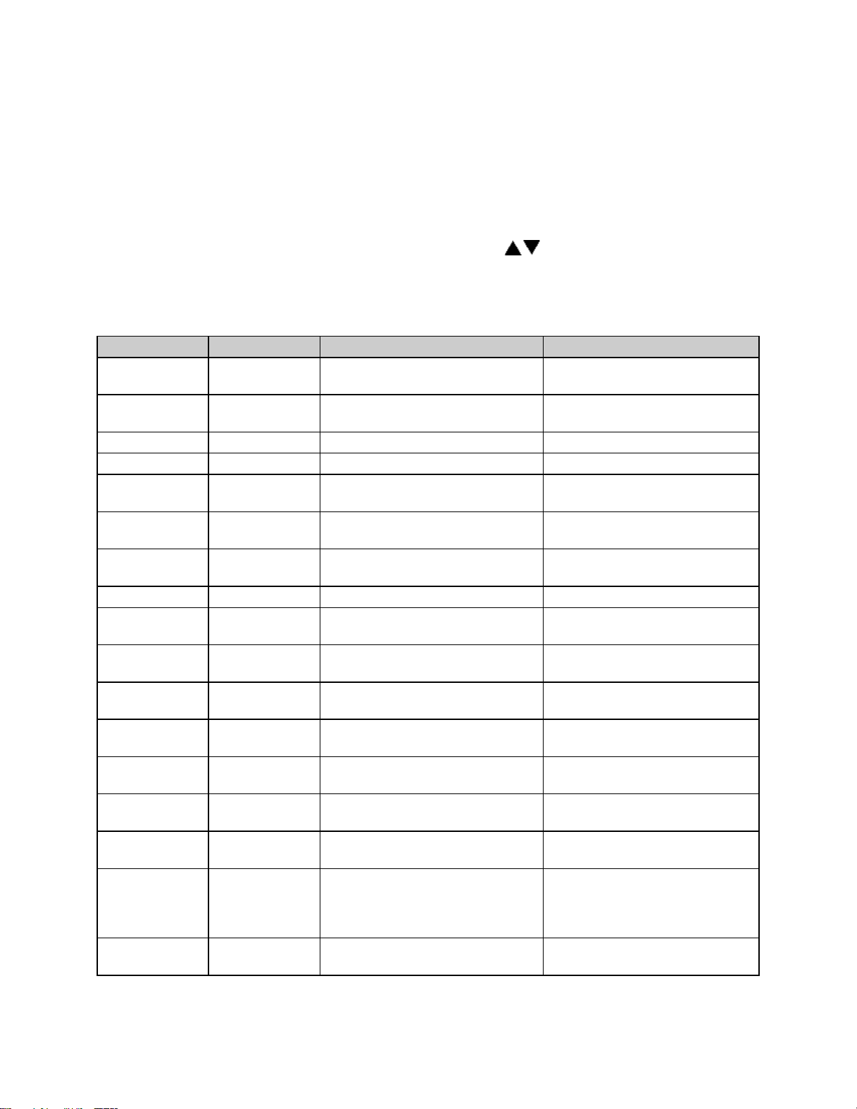
40
Enable Page
Menu Item
Display
Description
Range
Profiles
Enable Profile
1-8
Controls access to Program Page
Yes or No
Autostart
Enable Auto
Start
Controls access to AutoStart
Page
Yes or No
PID
Enable PID
Controls access to PID Page
Yes or No
Control
Enable Control
Controls access to Control Page
Yes or No
Communication
Enable
Communication
Controls access to
Communication Page
Yes or No
Real Time
Clock
Enable Clock
Controls access to Real Time
Clock Page
Yes or No
Relay outputs
Enable Relay
1-4
Controls access to Relay Page
Yes or No
Test
Enable Test
Controls access to Test Page
Yes or No
Zone
Calibration
Enable Zone
Cal
Controls access to Zone
Calibration Page
Yes or No
Sensor
Calibration
Enable Sensor
Cal
Controls access to Sensor
Calibration Page
Yes or No
Setpoint lower
limit
Enable
SPLowerLim
Sets minimum setpoint allowed
-73°C to 760°C (-100°F to 1400°F)
Setpoint upper
limit
Enable
SPUpperLim
Sets maximum setpoint allowed
-73°C to 760°C (-100°F to 1400°F)
High limit
overhead
Enable
HiLimOH
Sets maximum high limit setpoint
allowed*
3 to 11°C (5 to 20°F)*
Password level
1
Enable
Password 1
Sets password for access level 1
0 to 1000
Password level
2
Enable
Password 2
Sets password for access level 2
0 to 1000
Setpoint
Change
Enable
SPChange
Set to DISABLE to lock out
setpoint and high limit setpoint
changes in Manual and Timer
Modes
Yes or No
Analog Output
Type
Enable Analog
Type
Sets Analog Output type
Ctrl or Proc
The Enable Page controls access to the other Setup Pages. The setpoint minimum and
maximum values, and the security passwords are also set on the Enable Page.
To access the Enable Page, enter the Setup Mode using a level 2 access code (see
description earlier in this manual). Press the Page key until Enable is displayed. Press
the Menu key. Each parameter can be changed by pressing the Menu key until the
desired parameter is displayed, and then pressing the keys to change the value.
NOTE: Changing the enable to “yes” for each page will allow access to the page in
Level 1 security.
* Maximum high limit setpoint = SPUpperLim + HiLimOH
Page 50
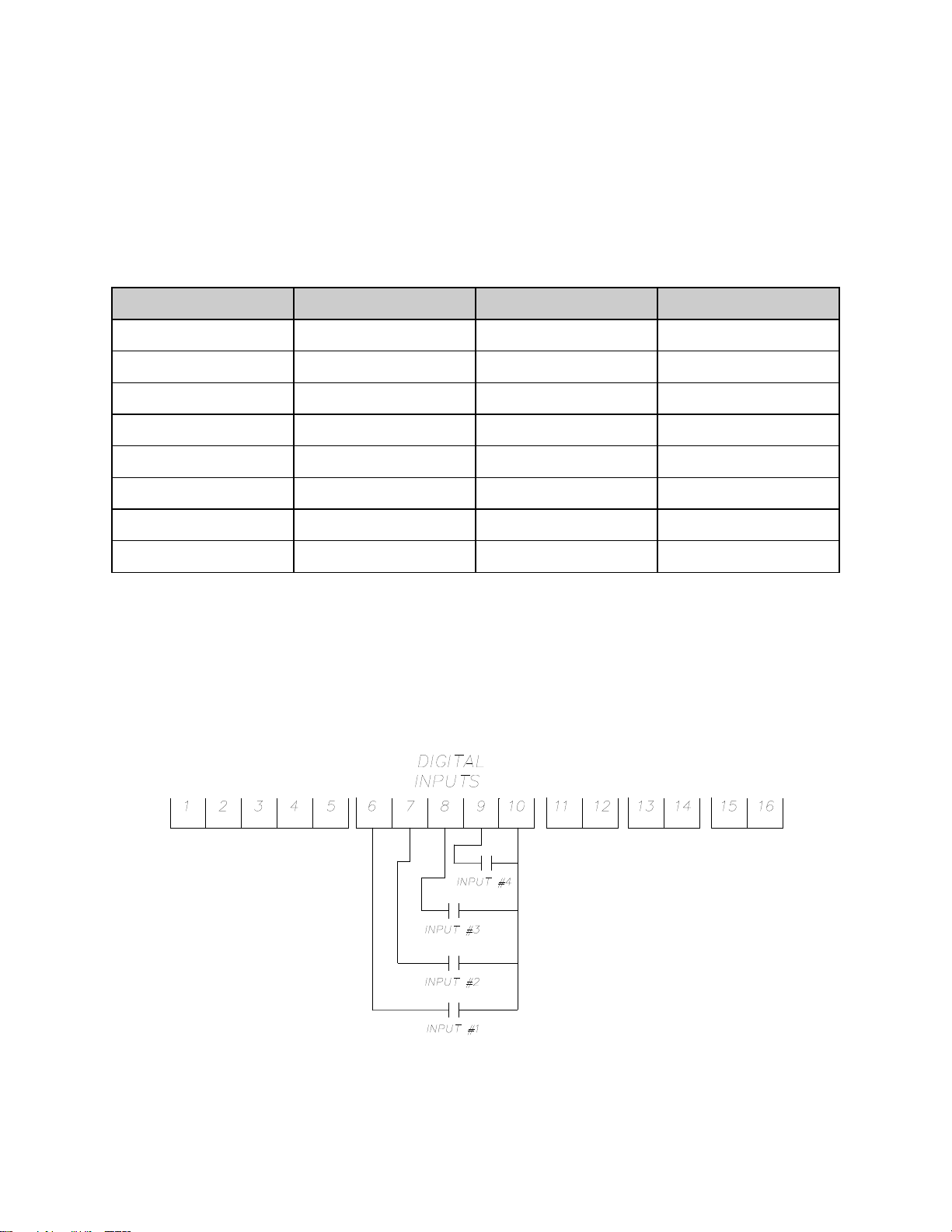
41
Digital Inputs (optional)
Input 1
Input 2
Input 3
Profile Selected
ON
OFF
OFF
1
OFF
ON
OFF
2
ON
ON
OFF
3
OFF
OFF
ON
4
ON
OFF
ON
5
OFF
ON
ON
6
ON
ON
ON
7
OFF
OFF
OFF
none
The Protocol Plus control can be run by external inputs wired to the control from an
external source such as a PLC or control panel switches. The external run operation
can Run, Hold or Stop profiles 1 through 7 (profile 8 can not be operated externally).
Refer to the table below for the inputs required for the desired operation. NOTE: A
profile must be created in the program page before trying to run a profile number.
To start the selected profile, set Input 1, 2, 3 or 4 to ON.
To hold a profile, set Input 4 to OFF.
To stop a profile, set all inputs to OFF.
Digital Inputs
Page 51

42
Error Messages and Alarms
The Alarm Status Hi-limit LED is flashing. This indicates a problem with the
thermocouple, or the Hi-limit setpoint has been exceeded. Once the problem has
corrected, press the Reset pushbutton.
The Alarm Status Soak LED is flashing. This indicates that the oven temperature has
not entered or dropped out of the soak band and the soak timer has stopped.
The top LED Display reads OPEN. This indicates that either the Control or the Hi-limit
thermocouple is disconnected or broken. The lower LCD display should indicate which
thermocouple is the problem. Repair or replace the thermocouple.
The lower LCD display reads CONTROL SENS ERR. This indicates that the Control
thermocouple is disconnected or broken. The upper LED display should indicate OPEN
showing a thermocouple problem. Repair or replace the thermocouple.
The lower LCD display reads HI-LIM SENS ERR. This indicates that the Hi-limit
thermocouple is disconnected or broken. Repair or replace the thermocouple.
The lower LCD display reads HIGH LIMIT ALARM. This indicates that the Hi-limit
temperature setpoint has been exceeded. Determine if the setting is set too close to the
setpoint, the SSR is defective, or the calibration is incorrect.
Page 52
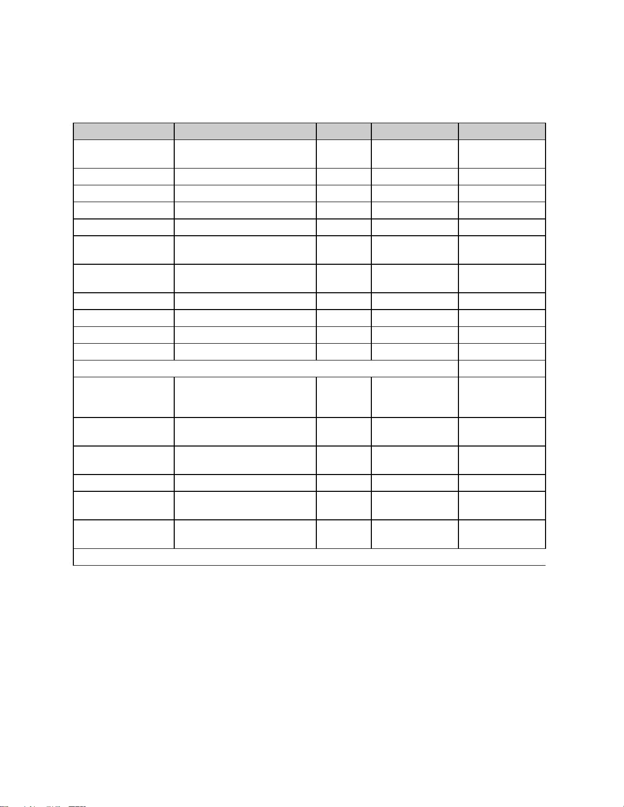
43
Quick Reference and Default Values
Menu Item
Display
Default
Range
Setting
Ramp Time Seg 1
Pro-1 Seg-1 Ramp Time
00:00
00m00s to
99h59s
Event 1 Set Value
Pro-1 Seg-1 Ramp Event 1
Off
Off, On
Event 2 Set Value
Pro-1 Seg-1 Ramp Event 2
Off
Off, On
Event 3 Set Value
Pro-1 Seg-1 Ramp Event 3
Off
Off, On
Event 4 Set Value
Pro-1 Seg-1 Ramp Event 4
Off
Off, On
Soak Temp Seg 1
Pro-1 Seg 1 Soak Temp
68°F
SPLowerLim to
SPUpperLim *
Soak Time Seg 1
Pro-1 Seg 1 Soak Time
00:00
00m00s to
99h59s
Event 1 Set Value
Pro-1 Seg-1 Soak Event 1
Off
Off, On
Event 2 Set Value
Pro-1 Seg-1 Soak Event 2
Off
Off, On
Event 3 Set Value
Pro-1 Seg-1 Soak Event 3
Off
Off, On
Event 4 Set Value
Pro-1 Seg-1 Soak Event 4
Off
Off, On
(repeat for segments 2-8)
High Limit Setpoint
Pro-1 Hi-Lim SP
Max
HiLimSP
MinHiLimSP to
MaxHiLimSP *,
Band **
Loop From
Pro-1 Loop From XX
No
No, Seg-1 to
Seg-8
Loop To
Pro-1 Loop To XX
No
No, Seg-1 to
Seg-8
Loop Count
Pro-1 Loop Number
0
0 to 99
Profile Link
Pro-1 Link To XX
Stop
Stop, Hold,
Pro-1 to Pro-8
Guaranteed Soak
Pro-1 Guar Band
Off
Off, 1 to 760°C
(1400°F)
(repeat for profiles 2-8)
Program Page
* See Enable Page
** Band value is set on Control Page
Page 53

44
Programming Table
Seg-
ment
Ramp
Soak
Time
Events
Temp-
erature
Time
Events
1 2 3 4 1 2 3
4
1 2 3 4 5 6 7 8 High Limit Setpoint
Loop From Seq
Loop To Seq
Loop Number
Link To Pro
Guar Soak Band
Profile Number__________
Profile Name__________
Page 54
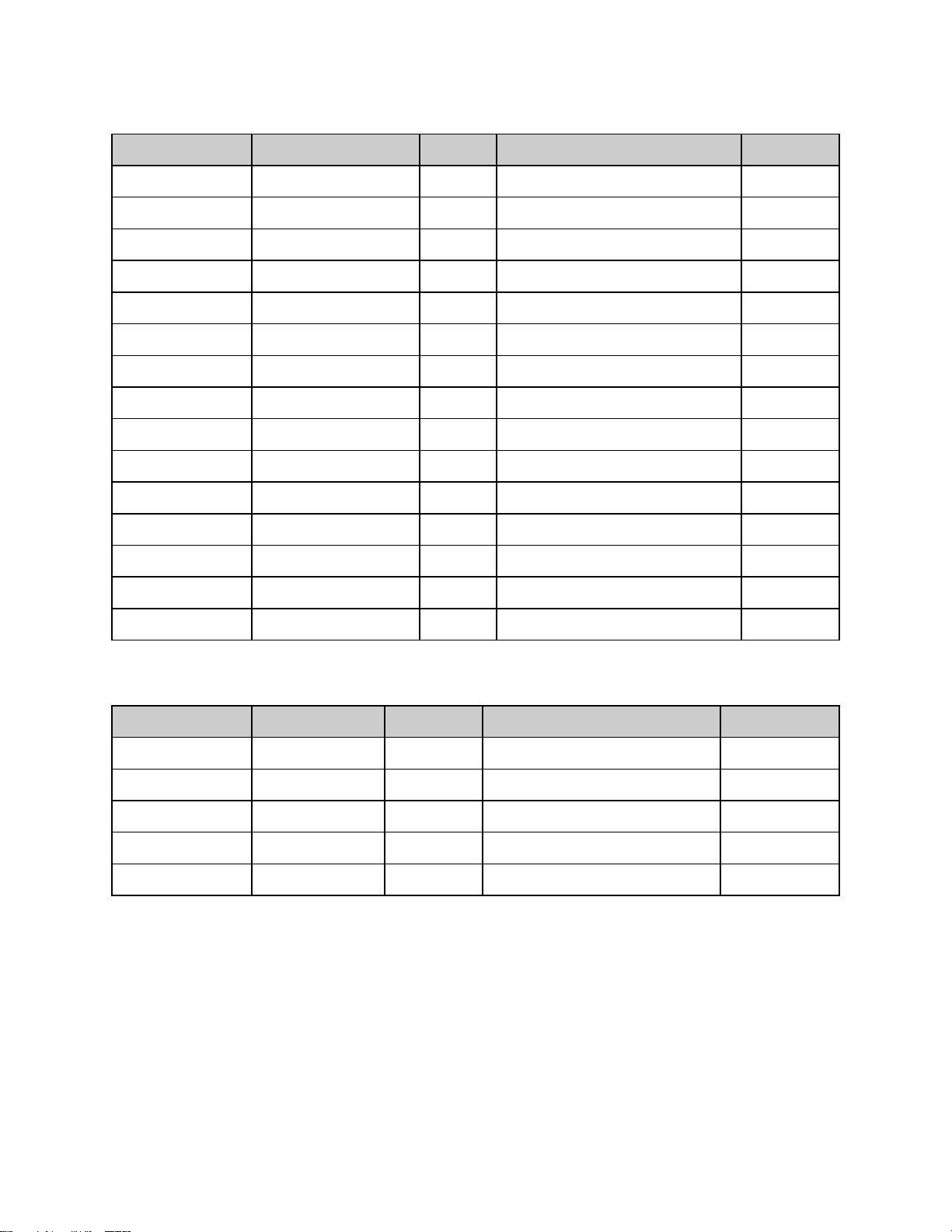
45
Autostart
Menu Item
Display
Default
Range
Setting
Enable Autostart
Auto Start Enable
No
No, Yes
Sunday mode
Auto Start Sun Mode
Off
Off, Manual, Timer, Pro-1 to Pro-8
Sunday time
Auto Start Sun Time
00:00
00:00 to 23:59
Monday mode
Auto Start Mon Mode
Off
Off, Manual, Timer, Pro-1 to Pro-8
Monday time
Auto Start Mon Time
00:00
00:00 to 23:59
Tuesday mode
Auto Start Tue Mode
Off
Off, Manual, Timer, Pro-1 to Pro-8
Tuesday time
Auto Start Tue Time
00:00
00:00 to 23:59
Wednesday mode
Auto Start Wed Mode
Off
Off, Manual, Timer, Pro-1 to Pro-8
Wednesday time
Auto Start Wed Time
00:00
00:00 to 23:59
Thursday mode
Auto Start Thu Mode
Off
Off, Manual, Timer, Pro-1 to Pro-8
Thursday time
Auto Start Thu Time
00:00
00:00 to 23:59
Friday mode
Auto Start Fri Mode
Off
Off, Manual, Timer, Pro-1 to Pro-8
Friday time
Auto Start Fri Time
00:00
00:00 to 23:59
Saturday mode
Auto Start Sat Mode
Off
Off, Manual, Timer, Pro-1 to Pro-8
Saturday time
Auto Start Sat Time
00:00
00:00 to 23:59
Menu Item
Display
Default
Range
Setting
Display units
PID Temp Unit
°C
°C or °F
Proportional band
PID Prop Band
6°C
1 to 56°C (1 to 100°F)
Integral reset
PID Reset
2
0 to 100 seconds/repeat
Derivative Rate
PID Rate
0
0 to 500 seconds
AutoTune
PID AutoTune
Disable
Disable, Enable
PID
Page 55
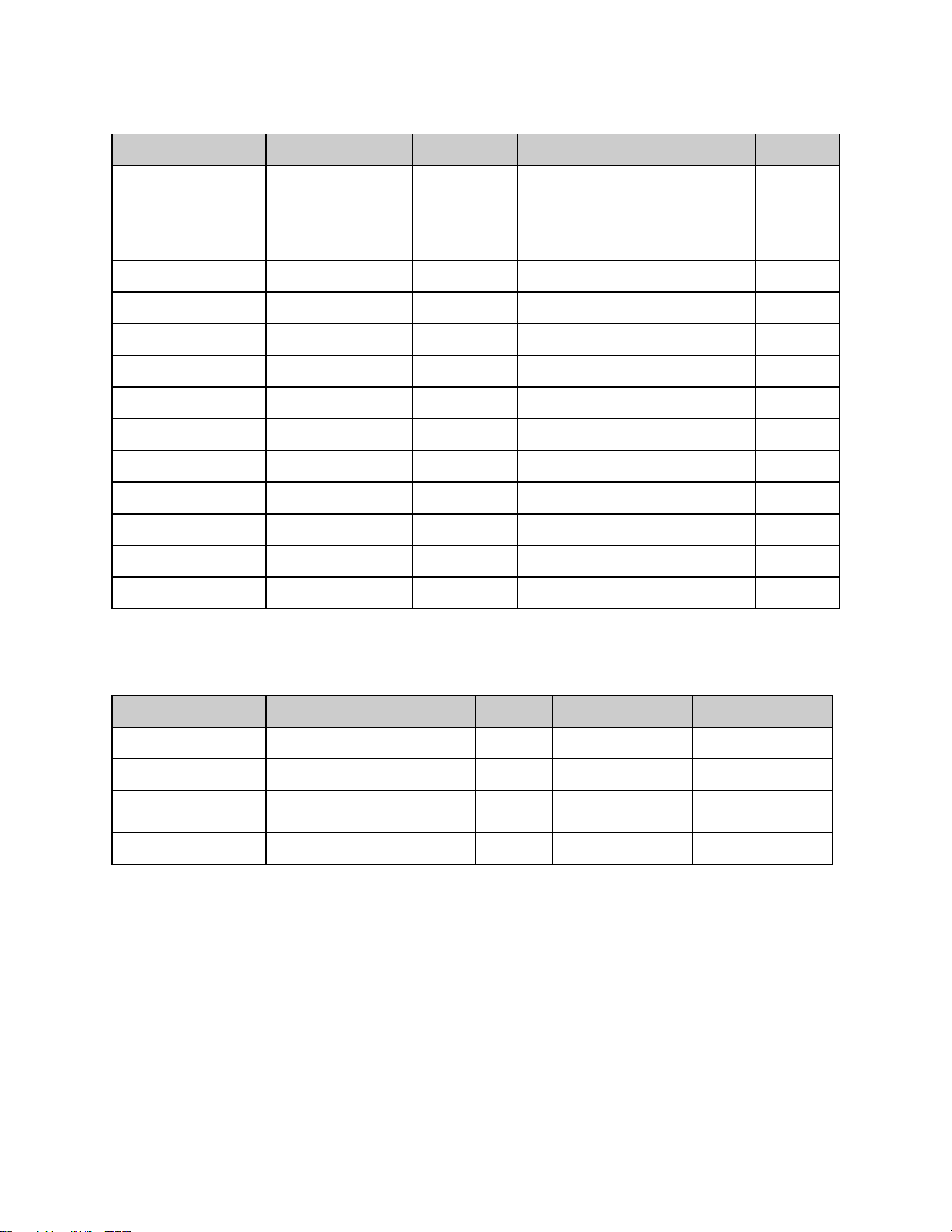
46
Control
Menu Item
Display
Default
Range
Setting
Cycle Time
Control Cycle Time
1
1 to 60 seconds
High limit setpoint
Control Hi-Lim SP
Max HiLimSP
MinHiLimSP - MaxHiLimSP*
High limit band
Control Hi-Lim Band
Off
Off, 3°C to 11°C (5°F to 20°F)
Power fail recovery
Control PwrFRec
Stop
Stop, Restart, Hold, Resume
Recovery time limit
Control PwrFTime
00m00s
00m00s to 99m59s
Powerup start enable
Control EPwrStrt
Dis
Dis, En
Powerup Start Mode
Control StrtMode
Off
Off, Manual, Timer, Pro-1 to Pro-8
Hysteresis
Control Hyst
3°C
1°C to 56°C (1°F to 100°F)
Process out low
Control RetOutLo
80°C
-73°C to 760°C (-100°F to 1400°F)
Process out high
Control RetOutHi
400°C
-73°C to 760°C (-100°F to 1400°F)
Time scale
Control TimeScale
hh:mm
hh:mm or mm:ss
Key press beep
Control KeyBeep
On
On or Off
End of cycle beep
Control EOCBeep
Off
On or Off
Alarm beep
Control AlarmBeep
Off
On or Off
Menu Item
Display
Default
Range
Setting
Address
Communication CommAddr
1
1 to 255
Mode
Communication CommMode
OFF
OFF, Modbus
Baud rate
Communication Baud Rate
19.2K
2400, 4800, 9600,
19.2K, 38.4K
Parity
Communication Parity
None
None, Odd, Even
*see Enable Page
Communication (optional)
Page 56
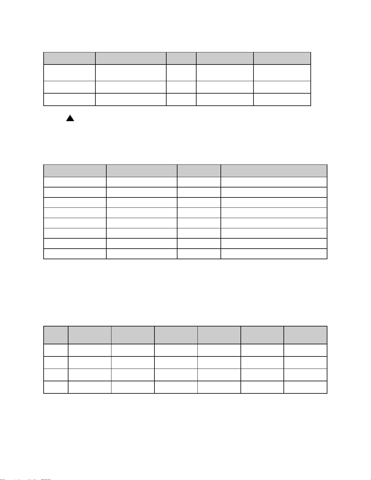
47
Real Time Clock
Menu Item
Display
Default
Range
Setting
Day of the week
Clock Day
Mon
Sun, Mon, Tue,
Wed, Thu, Fri, Sat
Time of day
Clock HH:MM
00:00
00:00 to 23:59
Reset clock
Clock UP to Reset CLK*
Ready
Ready, Done
Menu Item
Display
Default
Range
Type of relay
Relay 1 RelayType
Off
Off, Alarm, Cycl, Ev1 to Ev4
Action of relay
Relay 1 RelayAction
NDE
NDE, NE, NDEL, NEL*****
Type of alarm*
Relay 1 AlarmType
High
High, Low, Plus, Minus, Band
Alarm setpoint*
Relay 1 AlmHi/Lo SP
538°C
-73°C to 760°C (-100°F to 1400°F)
Alarm deviation*
Relay 1 AlmDevBand
3°C
1 to 56°C (1 to 100°F)
Inhibit alarm*
Relay 1 ALMInhibit
On
En or Dis
Type of event**
Relay 1 EventType
Time
Time or Temp
Event setpoint ***
Relay 1 Event SP
SPUpLim
SPLoLim to SPUpLim****
Relay
Type
Action
Alarm/
Event Type
Setpoint
Alarm
Deviation
Alarm
Inhibit
* if the key is not pressed, the clock values will retain their original values, the display
will change to Done if the clock is reset
Relay Outputs (optional)
Push Select key to select relay. If Relay 0 appears, no relays are installed
(repeat for relay outputs 2-4, if available)
* appears only for alarm types
** appears only for time or temperature event types
*** appears only for temperature event types
**** see enable page
***** Normally de-energized and non-latching, normally energized and non-latching, normally de-energized and
latching, normally energized and latching
Table of Settings
Page 57
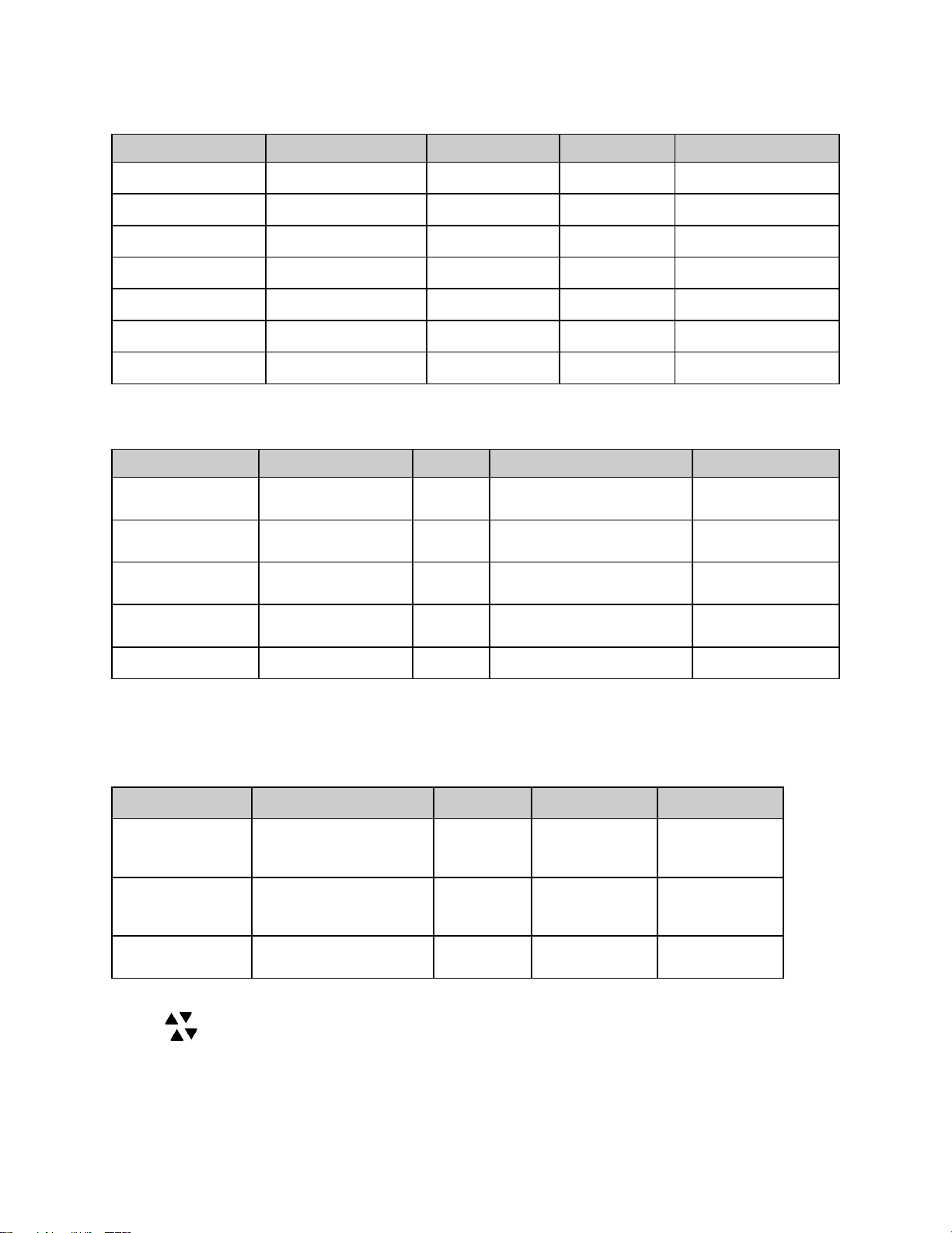
48
Test
Menu Item
Display
Default
Range
Setting
Heater output
Test HeatOut
Off
On High limit relay
Test HiLimOut
Off
On Relay 1 output
Test Rly1 Out
Off
On Relay 2 output
Test Rly2 Out
Off
On Relay 3 output
Test Rly3 Out
Off
On Relay 4 output
Test Rly4 Out
Off
On High Limit Sensor
Test HL Temp
(sensor reading)
Menu Item
Display
Default
Range
Setting
Zone 1 actual
Zone Cal Zone1Act
38°C
-73°C to 760°C (-100°F to
1400°F)
Zone1 displayed
Zone Cal Zone1Dis
38°C
-73°C to 760°C (-100°F to
1400°F)
Zone 2 actual
Zone Cal Zone2Act
260°C
-73°C to 760°C (-100°F to
1400°F)
Zone2 displayed
Zone Cal Zone2Dis
260°C
-73°C to 760°C (-100°F to
1400°F)
Factory calibration*
Zone Cal FactCal
Ready
Ready or Done (push- key)
Menu Item
Display
Default
Range
Setting
Control Sensor Cal
Ctrl Sens 0F
Ctrl Sens 1000F
Ctrl Sens Done
-100°F
1400°F
Done
-100 to 1400°F
-100 to 1400°F
(read only)
HiLim Sensor Cal
HL Sens 0F
HL Sens 1000F
HL Sens Done
-100°F
1400°F
Done
-100 to 1400°F
-100 to 1400°F
(read only)
Retransmit Cal
RetCalLo XXXX *
RetCalHi XXXX *
0
4096
0 to 4096**
0 to 4096***
Zone Cal
*only use when no calibration instrument is available
Sensor Cal
* note that the actual RetCalLo and RetCalHi values displayed are of no importance.
** press keys until retransmission output = 1VDC
*** press keys until retransmission output = 5VDC
Page 58

49
Enable Page
Menu Item
Display
Default
Range
Setting
Profiles
Enable Profile 1-8
Yes
Yes or No
Autostart
Enable Auto Start
No
Yes or No
PID
Enable PID
Yes
Yes or No
Control
Enable Control
No
Yes or No
Communication
Enable Communication
No
Yes or No
Real Time Clock
Enable Clock
No
Yes or No
Relay outputs
Enable Relay 1-4
No
Yes or No
Test
Enable Test
No
Yes or No
Zone Calibration
Enable Zone Cal
No
Yes or No
Sensor Calibration
Enable Sensor Cal
No
Yes or No
Setpoint lower limit
Enable SPLowerLim
20°C
-73°C to 760°C (-100°F to
1400°F)
Setpoint upper limit
Enable SPUpperLim
260°C
-73°C to 760°C (-100°F to
1400°F)
High limit overhead
Enable HiLimOH
5°C
3 to 11°C (5 to 20°F)*
Password level 1
Enable Password 1
1
0 to 1000
Password level 2
Enable Password 2
2
0 to 1000
Manual/Timer mode
setpoint change
Enable SPChange
Yes
Yes or No
Analog Output Type
Enable Analog Type
Proc
Ctrl or Proc
* Maximum high limit setpoint (MaxHiLimSP) = SPUpperLim + HiLimOH
Minimum high limit setpoint (MinHiLimSP) = SPLowerLim + HiLimOH
Page 59

50
Technical Specifications
UL, cUL listed:
UL file E136675
CE compliance to:
EMC Directive 89-366/EEC
European Standard EN55011/1991
European Standard EN50082-2/1995
Power supply:
100 to 240 VAC +10% -15%, 50-60Hz, 30VA Maximum
12 to 24 VAC/VDC +/-10%, DC to 60Hz, 30VA Maximum
Temperature:
Storage -20 to 60°C
Operating 0 to 50°C
Humidity:
90% or less, non-condensing
Sensor inputs:
Type J thermocouple -73°C to 760°C (-100°F to 1400°F)
Input impedance 1M ohm or greater
Common mode noise rejection of 140db@60Hz
Common mode input voltage of +/-12.0VDC
Sample rate of at least 1 sample per second
Stability of +/- 0.5°C per 5°C change in ambient temperature
Repeatability of +/- 0.5°C, or +/-0.1% of sensed temperature (whichever is
greater)
Accuracy (@ 77°F +/-0.2 percent of span (+/-3°F)
Supply Voltage Influence of +/-0.5°C per 10% change in nominal line voltage
Temperature
display:
1 degree resolution (C or F)
Accuracy after calibration of +/- 1°C, or +/-0.2% of sensed temperature
(whichever is greater) @25°C
Four-digit seven-segment LCD, 0.43 inches high (11mm)
Readout Stability (+/-1°F/10°F Change in ambient temperature)
Message display:
Two-line, 16 alpha-numeric 5x7 dot matrix characters per line
0.2 inches high (5mm)
Time base:
+/- 4 seconds accuracy in 24 hours
Heat control
output:
SSR Drive 24VDC nominal @ 70mA
Relay output: (plug-in
module)
Form A dry contact, rated 3 amps @ 24-264VAC
Retransmit output:
0 to 5 VDC into > 100K ohm load or 4-20maDC > 0-800 Ohm Load (+/-0.2% of
programmed span accuracy, +/- 1LSD)
Communications:
(plug-in module)
RS232 Single drop, isolated
RS422 Multi-drop, isolated
RS485 Multi-drop, isolated
Remote inputs:
(plug-in module)
Dry-contact closure type with less than 250 ohm ON resistance
Front panel:
NEMA 4X (with gasket)
Dimensions:
3.57H x 7.24W x 2.84D inches (91H x 184W x 72D mm)
Panel opening:
3.63H x 7.30W inches (92H x 185W mm)
Page 60

51
MAINTENANCE
Do not attempt any service on this oven before opening the main power disconnect
switch.
Checklist
Keep equipment clean. Gradual dirt accumulation retards air flow. A dirty oven
can result in unsatisfactory operation such as unbalanced temperature in the
work chamber, reduced heating capacity, reduced production, overheated
components, etc. Keep the walls, floor and ceiling of the oven work chamber
free of dirt and dust. Floating dust or accumulated dirt may produce unsatisfactory work results. Keep all equipment accessible. Do not permit other
materials to be stored or piled against it.
Protect controls against excessive heat. This is particularly true of controls,
motors or other equipment containing electronic components. Temperatures
greater than 51.5°C (125°F) should be avoided.
Establish maintenance & checkup schedules. Do this promptly and follow the
schedules faithfully. Careful operation and maintenance will be more than paid
for in continuous, safe and economical operation.
Maintain equipment in good repair. Make repairs immediately. Delays may be
costly in added expense for labor and materials and in prolonged shut down.
Practice safety. Make it a prime policy to know what you are doing before you do
it. Make CAUTION, PATIENCE, and GOOD JUDGEMENT the safety
watchwords for the operation of your oven.
Lubrication, Fan motor bearings are permanently lubricated. All door latches,
hinges, door operating mechanisms, bearing or wear surfaces should be
lubricated to ensure easy operation.
Page 61

52
Tests
Tests should be performed carefully and regularly. The safety of personnel as well as
the condition of equipment may depend upon the proper operation of any one of the
functions of the temperature control. Test the control every 40 hours. Check that the
heater LED is cycling on and off, indicating that the heater is working. Also check the
high limit function to make sure it is working properly.
To test the high limit:
1. Go to Manual Mode and enter control setpoint value at least 20°F (11°C) lower
than the current process temperature.
2. Press the Menu key and lower the high limit setpoint to a value just below the
current process temperature.
3. The high limit alarm indicator should flash and a high limit alarm message should
be displayed. Verify that the heater relay has been disabled by checking that
2LED on the control panel circuit board is not lit.
4. Return the control setpoint and high limit setpoint values to their original values.
5. Press the Reset key.
Page 62

53
Replacement
WARNING:
Disconnect the main power switch or power cord before attempting any repair or adjustment.
Parts
To order or return parts, contact the Service Products Division at Despatch. The
Service Products features our Response Center for customer service. When returning
parts, a Despatch representative will provide you with an MRA (Material Return
Authorization) number. The MRA number must be attached to the returned part for
identification. When you are ordering parts, be sure to give the model number, serial
number and the part number. This will expedite the process of obtaining a replacement
part.
When you have a service need, contact the Response Center at 1-800-473-7373: FAX
612-781-5353.
Page 63

54
Protocol Plus™ Instrument
(Tools needed: 1/4" socket driver with #1 bit, #2 Phillips screwdriver)
1. Disconnect the power.
2. Remove the screws from the sides of the control panel and slide it forward.
3. Unplug all terminals on the rear of the control, noting the proper connections.
4. Remove the four retaining clips for the control.
5. Remove the control.
6. Insert the new control into the panel.
7. Fasten the four retaining clips.
8. Re-plug all terminals.
9. Fasten the control panel.
Heater Unit
(Tools needed: 3/8" wrench, square recess driver with #1 bit)
1. Remove the floor plate.
a. Remove the screws from the floor plate.
b. Lift the floor plate out of the oven.
2. Disconnect the heater leads from heater element with wrench. Note which wires
go on which terminals.
3. Unscrew the screws holding the heater frame to the oven body.
4. Remove the heater and discard.
5. Screw down the new heater frame.
6. Attach the heater leads to appropriate terminals.
7. Replace the interior floor and screws.
Page 64

55
Fan Motor
(Tools needed: Square recess driver w/#1 bit, 5/32 inch Allen wrench, one quarter (¼)
inch socket set)
1. Remove the screws from the sides of the control panel and slide forward.
2. Unplug the motor harness from the circuit board and remove motor and heater
ground wires from ground stud.
3. Unplug heater leads from circuit board and thermocouple leads from control.
4. Pull off fresh air damper handle from damper arm.
5. Remove screws holding fresh air damper arm assembly to control panel.
6. Remove the chamber floor plate.
a. Remove the screws from the floor plate.
b. Lift the floor plate out of the oven.
7. Remove the left side wall.
8. Remove fan and heater plug assembly from oven by lifting on the air outlet of the
assembly and pushing from underneath.
9. Remove heater (do not disconnect wires).
10. Remove the fan inlet plate.
11. Loosen the set screws (2) on fan wheel and remove wheel.
12. Remove the screws (4) holding the fan motor in place.
13. Remove the fan motor.
14. Install the fan motor.
a. Insert shaft seal onto shaft.
b. Insert the shaft into shaft collar.
c. Fasten motor to plug assembly with the four screws.
15. Install fan wheel onto motor shaft.
Page 65

56
16. Replace and fasten the fan inlet cover.
17. Adjust the fan wheel for 3/16 inch clearance between the wheel and the inlet ring
and tighten the set screws on the fan wheel. Check that the set screws hit the
flats machined into the motor shaft.
18. Replace and fasten heater.
19. Replace fan and heater plug assembly in oven body.
20. Replace left side wall.
21. Replace and fasten floor plate.
22. Replace fresh air damper arm assembly.
23. Replace fresh air damper handle.
24. Connect heater leads to circuit board.
25. Connect motor wire harness and fasten motor and heater ground wires to ground
stud.
26. Connect thermocouple wires to control.
27. Replace control panel in oven body.
Page 66

57
TROUBLESHOOTING
Difficulty
Probable Cause
Suggested Remedy
Failure to heat
No power
Broken or frayed cord
Burned out heater
Protocol™ malfunction
Loose wire connections
Heater relay failure
Door switch failure
Check power source and/or oven and wall fuses.
Replace with new cord.
Replace heater (see warranty.)
Replace controller.
Disconnect power and check connections behind
control panel.
Replace circuit board.
Replace door switch.
Slow heat up
Improperly loaded
Low line voltage
Heating element(s) are
burned out
240 volt oven is connected to
a 208V line
Fan motor failure
Reduce load or redistribute load in chamber.
Supply sufficient power and proper connections.
Check for circuit overload.
Replace burned out element (see warranty
statement.)
Raise line voltage to a 240 volt line or modify
oven for 208V operation (consult factory).
Replace fan motor.
Frequent heater
element out
Harmful fumes generated by
load
Spillage or splattering of
material on heater elements
Overheating oven
Increase vent opening or discontinue process.
Disconnect power and clean oven chamber and
elements.
Check the Hi-limit.
Erratic temp. or
inaccurate temp.
Protocol™ malfunction
Improper tuning parameters
Protocol™ miscalibration
Hi-limit setting
Improper offset
Replace Protocol™.
Check tuning parameters.
Recalibrate Protocol™ (see section on Calibra-
tion mode.)
Hi-limit should be 10-25°C higher than setpoint.
Check zone calibration.
Equipment which operates for long periods of time may develop problems. Below are
possible problems and suggested solutions. If you have a problem not listed and do not
know what to do, contact Despatch Industries at our toll free Help Line 800-473-7373.
Page 67

58
Difficulty
Probable Cause
Suggested Remedy
Excess surface or
door temp.
Door seal deterioration
Replace door seal.
Improper airflow
Fan motor failure
Fan wheel seated too low on
fan shaft
Unbalanced fan wheel
Replace fan motor.
Adjust fan wheel for 3/16" clearance between
wheel and inlet ring.
Replace fan wheel.
Excessive
vibration
Dirty fan wheel
Unbalanced fan wheel
Clean fan.
Replace fan wheel.
Oven will not
control at setpoint
Hi-limit set too low
Protocol malfunction
SSR malfunction
Air friction of recirculation fan
Set the Hi-limit higher
Replace control.
Replace SSR and/or check control output
voltage.
Open exhaust air vent. Unit will not control below
minimum operating temperature with vent closed.
Heater does not
shut down until
temp. reaches the
Hi-limit setting
Protocol malfunction
SSR malfunction
Replace Protocol
Replace SSR
NOTE: The circuit board mounted on the control panel has three status LED indicators
to help troubleshoot if the oven is not heating.
A. If LED 1 is not lit, check 2F and 3F (control fuses), or power switch.
B. If LED 1 and LED 3 are lit but not LED 2, check high limit (and optional door
switch, if installed).
C. If all three LEDs are lit, check 1F and 4F (heater fuses), SSR, heater, and heater
relays.
Page 68
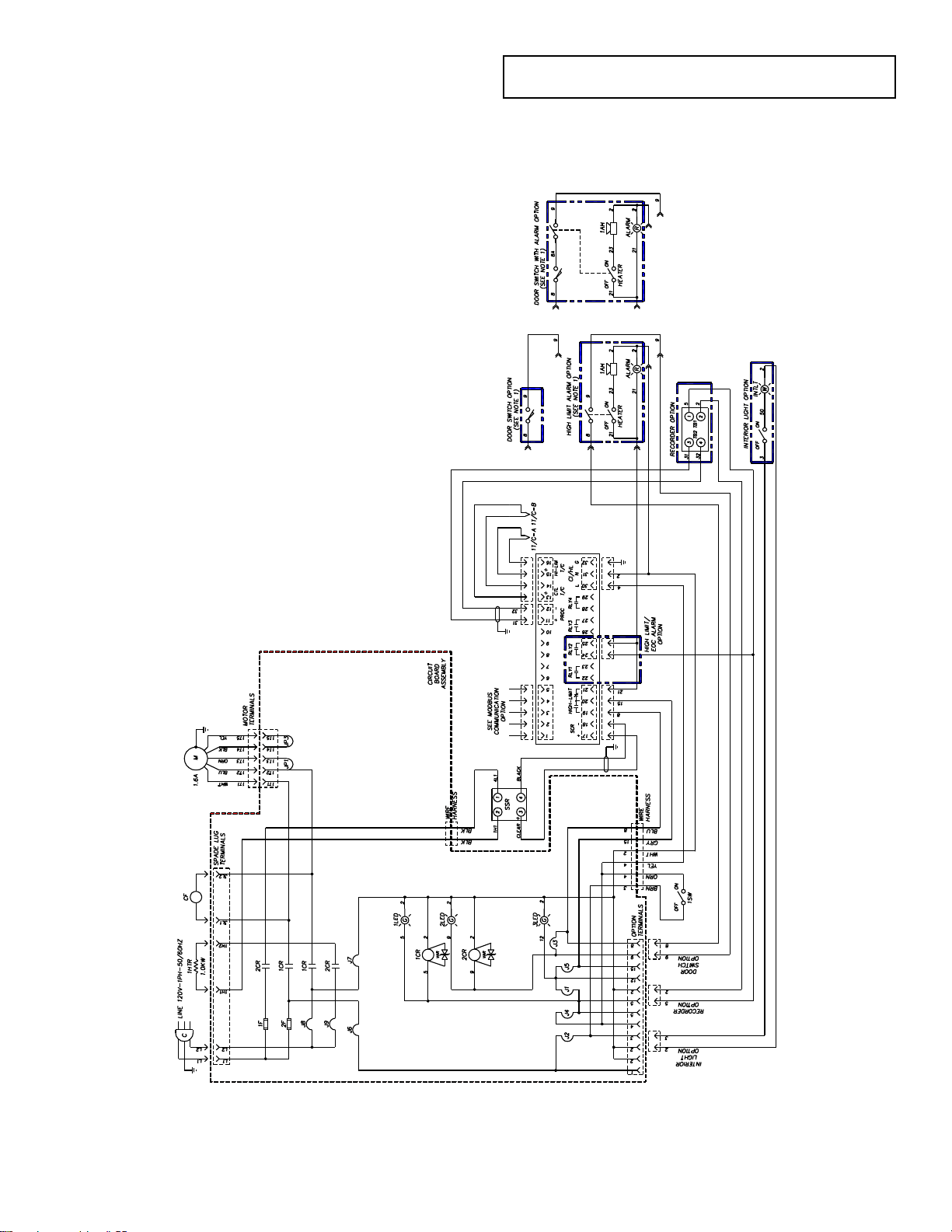
59
DRAWINGS
Excerpt from drawing 141852H1, 8-2000
LAC1-10-5
Page 69
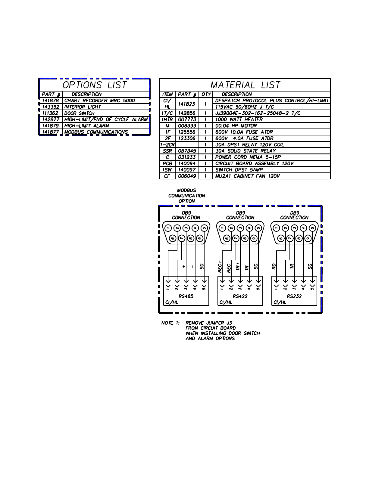
60
LAC1-10-5 Data
Page 70
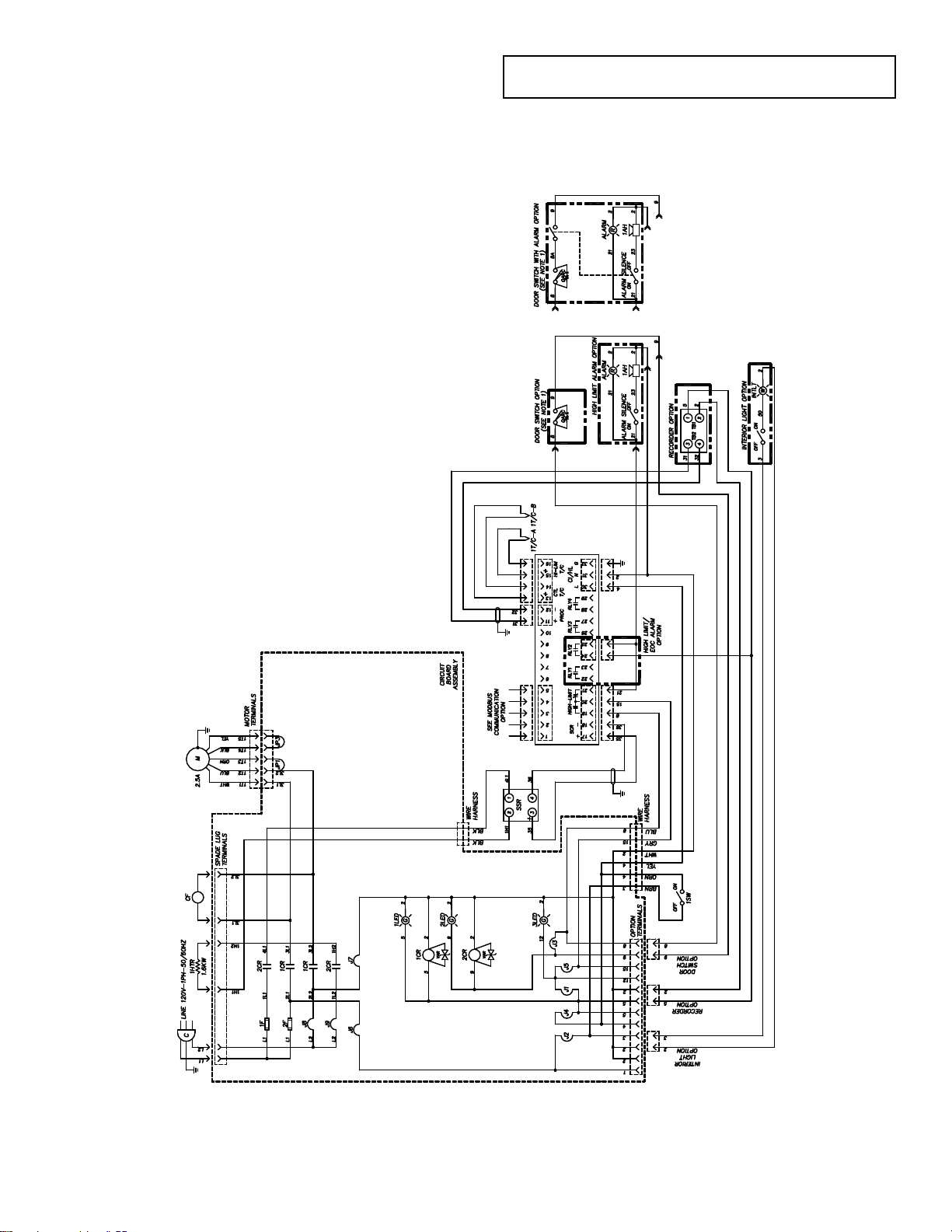
61
LAC1-38A-5
Excerpt from drawing 141853F1,4-2000
Page 71
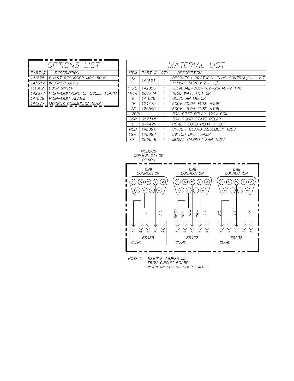
62
LAC1-38A-5 Data
Page 72
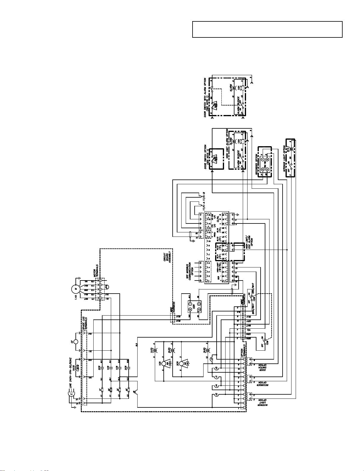
63
LAC1-38B-5
Excerpt from drawing 141854G1, 4-2000
Page 73

64
LAC1-38B-5 Data
Page 74

65
LAC1-67-5
Excerpt from drawing 141855G1, 4-2000
Page 75
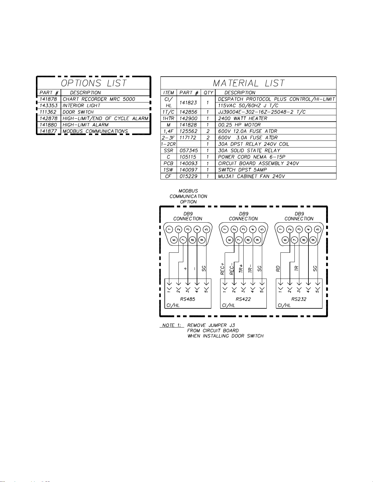
66
LAC1-67-5 Data
Page 76

67
LAC2-12-5
Excerpt from drawing 141856G1, 4-2000
Page 77

68
LAC2-12-5 Data
Page 78

69
LAC2-18-5
(Excerpt from drawing 141857G1, 4-2000)
Page 79

70
LAC2-18-5 Data
Page 80

71
APPENDIX: Temperature Scale
Conversion and Optional MRC5000
Setup
Temperature Scale Conversion (C/F)
The Protocol Plus controller can be operated in either C or F. The default setting for the
controller is C. Changing from one to the other is as follows:
1. Go into the Setup Mode on the controller.
2. Press the Select Key until Setup is displayed.
3. Press the Page key and Security will be displayed.
4. Press the Menu Key and Password will be displayed. Use the arrow keys to
enter the proper password. The default password is 2 for level two.
5. Once the proper password is displayed, press the Page key until PID is
displayed.
6. Press the Menu key and Temp Unit along with C or F will be displayed. Use the
arrow keys to change the setting.
7. Once the proper setting is displayed, press and hold the Page key for
approximately three seconds to exit the Setup Mode.
Page 81
72
Optional MRC5000 Recorder Setup
Parameter Code
Degrees C
Degrees F
Inps
18
18
Icor
0 0 diSP
On
On
dPOS
0 0 EUU **
400
752
EUL **
0
32
ChUP
400
800 *
ChLO
0 0 DFF
1
1
The temperature is retransmitted to the Recorder from the Controller. Set up the
Recorder as follows:
1. Make sure that jumper JU1 is setup for the 5 VDC setting (see MRC Manual).
2. Move the Mode switch to the PROG/TEST/CAL position, and Prog will be
displayed.
3. Press the down arrow key twice and Inps will be displayed. Make sure the
settings are per the table below.
4. Once all the settings have been changed, move the Mode switch to the RUN
position. The display on both the Recorder and controller should read the same.
* Note: The 0 - 400 chart paper must be changed to the 0 - 800 chart paper.
** Note: These values must mach the setting sRetOutLo and RetOutHi on the
Depending on the equipment, 0 - 600 paper can be used if the maximum
temperature is 500 degrees F.
Control page on the Protocol Plus controller (example: RetOutLo is 32,
then EUL must read 32).
 Loading...