

Page 1

C-191
PN 208712
REVISION B
12/2002
DES2000 CONTROL
INSTRUCTION MANUAL
Page 2

NOTICE
Users of this equipment must comply with operating procedures and training of
operation personnel as required by the Occupational Safety and Health Act (OSHA) of
1970, Section 6 and relevant safety standards, as well as other safety rules and
regulations of state and local governments. Refer to the relevant safety standards in
OSHA and National Fire Protection Association (NFPA), section 86 of 1990.
CAUTION
Setup and maintenance of the equipment should be performed by qualified personnel
who are experienced in handling all facets of this type of system. Improper setup and
operation of this equipment could cause an explosion that may result in equipment
damage, personal injury or possible death.
Dear Customer,
Thank you for choosing Despatch Industries. We appreciate the
opportunity to work with you and to meet your heat processing needs. We
believe that you have selected the finest equipment available in the heat
processing industry.
At Despatch, our service does not end after the purchase and delivery of
our equipment. For this reason we have created the Service Products
Division within Despatch. The Service Products Division features our
Response Center for customer service. The Response Center will direct
and track your service call to ensure satisfaction.
Whenever you need service or replacement parts, contact the Response
Center at 1-800-473-7373: FAX 612-781-5353.
Thank you for choosing Despatch.
Sincerely,
Despatch Industries
Page 3
i
ii
Page 4
iii
Page 5

TABLE OF CONTENTS
INTRODUCTION ............................................................................................................. 1
OPERATION ................................................................................................................... 3
Parameter Programming Mode ................................................................................... 4
Changing Display From °C To °F ................................................................................ 8
Oven Zone Calibration ............................................................................................... 10
APPENDIX .................................................................................................................... 11
Troubleshooting ......................................................................................................... 11
Technical Specifications ............................................................................................ 13
Page 6

iv 1
Page 7
INTRODUCTION
Features
Description
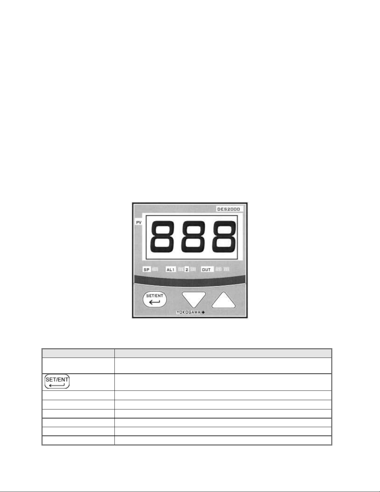
Main Display
Displays the actual oven temperature or displays the setpoint when the set
key is pressed. Displays parameter code and value.
Key
Switches between PV and SP displays. Enters the data changed by the or
keys. Switches through parameter displays.
Down Key
Decreases a setpoint or mode parameter.
Up Key
Increases a setpoint or mode parameter.
LED SP Indicator
Lights when the setpoint value is displayed.
LED OUT Indicator
Lights when the control is calling for heat.
LED AL1 –2 Indicator
N/A
LED PV Indicator
Lights when process variable is displayed.
The features of the DES2000 controller include:
PID Tuning
Display can show process variable or setpoint during normal operation
Solid state output to operate a solid state relay
The DES2000 controller is a microprocessor-based digital control instrument. The
instrument can be configured as a proportional controller. Initially the CONTROL will
allow the heater to operate at full power. However, as the actual oven temperature
reaches the setpoint, the Proportional Control will cycle the heater on and off,
minimizing process temperature fluctuations.
Figure 1. DES2000 CONTROL Instrument
Table 1 CONTROL Instrument Features
Page 8

2
Figure 2. DES2000 CONTROL Instrument Connections
Page 9
3
OPERATION
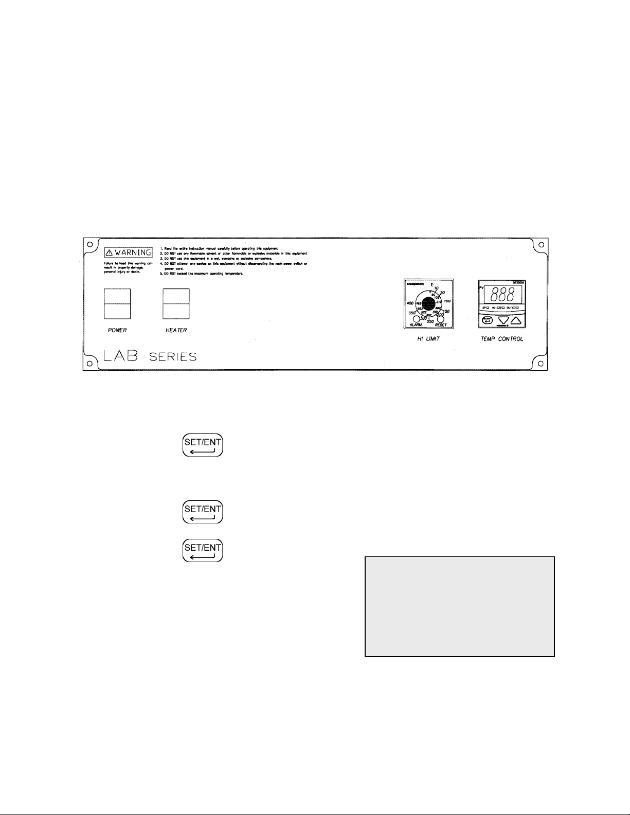
NOTE:
If the HI-LIMIT instrument is
exceeded the heater will shut
down. Reset the HI-LIMIT by
pushing the reset button on the
HI-LIMIT instrument.
For fastest oven heat-up time, close the exhaust vent. After the desired temperature is
reached, the vent may be adjusted as needed.
1. Start oven.
a. Turn POWER switch to on.
Figure 3. Typical Control Panel
2. Enter setpoint on the CONTROL instrument.
a. Press key until the SP LED is lit.
b. Use ▲ key and ▼ key to set operating temperature.
c. Press key to enter setpoint.
d. Press key again to display
process temperature.
Set HI-LIMIT instrument to a temperature 10°C to
14°C higher than the setpoint or to a temperature
that should not be exceeded in the process.
Page 10

4
Parameter Programming Mode
WARNING: Make sure you
understand what you are
changing before doing so.
Changing the program
parameters will alter the
functions of the CONTROL.
The control parameters are set through the
Operating and Set-up modes. In most applications, it
is not necessary to alter the oven settings. The
following instructions describe how to access, view
and, if desired, change the parameters.
Once the Operating and Set-up modes are
accessed, the SP LED will start blinking on and off.
The CONTROL will not allow the display to be altered improperly.
The CONTROL will automatically exit the Parameter Programming mode if no keys are
pressed for about two minutes.
Operating Parameters
1. Press key for three (3) seconds.
2. Press the key until the desired
parameter is displayed. See Operating and
Setup Parameter Tables on the following
pages.
3. Press the ▲ or ▼ once to display value.
4. Use the ▲ or ▼ to the desired setting.
5. Press the key to enter the value.
6. Press and hold the key for three (3) seconds to return to the display
mode.
On the next page are the parameter codes, listed in order as they appear.
Page 11
5
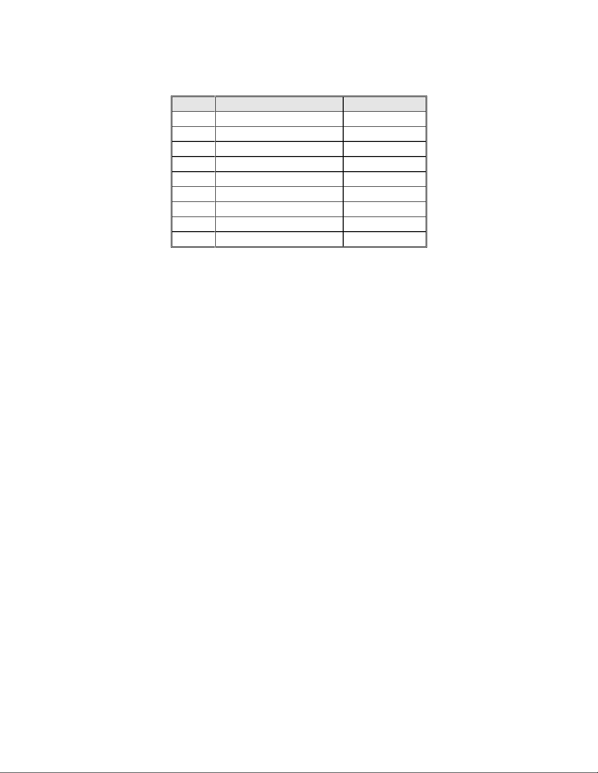
Table 2 Operating Parameter Outline
Code
Name
Settings
CtL
Control Mode
PID
At
Auto-tuning
OFF
P *
Proportional Band
5 **
I
Integral Time
120
d
Derivative Time
0
Ct
Cycle Time
1
FL
Input Filter
2
bS
PV Bias (Offset)
0
LoC
Key Lock
0
* If P is not displayed the Control Mode (CtL)
must be first set to Pid.
** For F change to value 13.
Definitions for Table 2:
CtL Control Mode - This parameter determines whether controller functions as a time
proportional or an on/off control.
At Auto-tuning – Off for PID tuning, ON for controller to tune process.
P Proportional Band - Expressed in degrees. This value determines the band width on
both sides of the setpoint within which the control provides proportional control.
I Integral Time - Expressed in seconds. This parameter corrects for errors in actual
temperature versus the setpoint.
D Derivative Time - Expressed in seconds. This effect of the derivative time is in direct
proportion to the time setting.
Ct Cycle Time - Expressed in seconds. This is the total time for one ON/OFF cycle of the
controller output during the proportional action.
FL Input Filter – Expressed in seconds. This function should be used when the PV may
fluctuate greatly (i.e. input signal contains noise).
bS PV Bias - Expressed in percent of span. From –100 to 100% of span, this parameter
used to set the actual oven temperature to the controller display.
LoC Key Lock - This provides levels of access to the controller.
0 = No key lock, full access to controller.
1 = Prevents changing of all parameters except setpoint.
2 = Prevents all parameters from being changed including the setpoint.
–1 = Set to enter the Setup parameter setting display.
When LoC = -1, the parameters are displayed in the order shown in the Set-Up
Parameters section, below.
Page 12

6
Set-Up Parameters
Oven Model
Degrees F
Degrees C
Maximum
Minimum
Maximum
Minimum
LAC
500
95
260
35
LAD/LFD/LND/LXD
650
95
343
35
LBB
400
86
204
30
Code
Parameter Name
Setting
In
Input Type
5
SPH
Maximum Setpoint Limit
Use value from Table 5 (below)
SPL
Minimum Setpoint Limit
Use value from Table 5 (below)
SC
Super Function
OFF
dr
Direct/Reverse Action
0
DSP
Display Priority
0
Code
Parameter Name
Setting
In
Input Type
35
SPH
Maximum Setpoint Limit
Use value from Table 5 (below)
SPL
Minimum Setpoint Limit
Use value from Table 5 (below)
SC
Super Function
OFF
dr
Direct/Reverse Action
0
DSP
Display Priority
0
1. Go into the operating parameters and change the LOC parameter to –1 and
press the SET/ENT key to access the Setup Parameters.
Table 3 Set-Up Parameters for Degrees Centigrade
Table 4 Set-Up Parameters for Degrees Fahrenheit
Table 5 Oven Models and Temperatures
NOTE: If the “In” code is changed, the “P” code in the operating parameters may have
to be reset.
2. Press and hold the key for three seconds to return to normal operation.
Page 13

7
Definitions for Tables 3 and 4:
Input type
Range ºC
Range
code ºC
Range ºF
Range
code ºF
Thermocouple
K
-199 to 999ºC
1
-199 to 999ºF
31
0 to 600ºC
2
32 to 999ºF
32
0 to 400ºC
3
32 to 750ºF
33
-199 to 200ºC
4
-199 to 400ºF
34 J -199 to 999ºC
5
-199 to 999ºF
35 T -199 to 400ºC
6
-199 to 750ºF
36 E -199 to 999ºC
7
-199 to 999ºF
37 L -199 to 900ºC
12
-199 to 999ºF
42 U -199 to 400ºC
13
-199 to 750ºF
43
RTD
Pt100
-199 to 850ºC
15
-199 to 999ºF
45
0 to 400ºC
16
32 to 750ºF
46
-199 to 200ºC
17
-199 to 400ºF
47
-19.9 to 99.9ºC
18
JPt100
-199 to 500ºC
19
-199 to 999ºF
48
In Input Type - See Input Range Codes (Table 6)
SPH Setpoint High - This should be set to the maximum operating temperature of the
equipment.
SPL Setpoint Low - This is the minimum operating temperature of the equipment.
dr Direct/Reverse Action - For heating this should be reverse acting
0 = reverse 1 = direct
DSP Priority of the display - This is the value to be displayed in normal operation
0 = process variable 1 = setpoint
Table 6 Input Range Codes
Page 14

8
Changing Display From °C To °F
WARNING: Make sure
you understand what
you are changing
before doing so.
Changing the program
parameters will alter the
functions of the
CONTROL.
NOTE: To change from
°F to °C repeat the
above steps. The
following are the values
to be entered:
In = 5
SPH = 204
SPL = 0
P = 5
The control can be configured for either °C or °F. Use the following steps to change
control from displaying °C to °F.
1. Press and hold the for three (3) seconds.
2. The display will read CtL. The SP LED will flash
indicating that Operating Parameter mode has been
entered.
3. Press the until LoC appears on the display.
4. Press the ▲ or ▼once to enter the parameter.
5. Press the ▼ to set the value to –1. The SP LED will flash rapidly, indicating that
the Set-Up Parameter mode has been entered.
6. Press the to enter the value. The display will read In.
7. Press the ▲or ▼ once to enter the parameter.
8. Press the ▲ to set the value to 35. The right decimal point LED will flash
indicating that the setting is being changed. This will stop flashing when the new
value has been entered.
9. Press the to enter the value.
10. Press the until SPH is displayed.
11. Press the ▲ to set the value to 400.
12. Enter a value of 400.
13. Press the to enter the value.
14. Repeat steps 12 –14 for SPL; the value is 32.
15. Press and hold the for three (3) seconds to return to the operation mode.
Page 15

9
16. Press and hold the for three (3) seconds.
17. The display will read CtL. The SP LED will flash indicating that Operating
Parameter mode has been entered.
18. Press the until P appears on the display.
19. Press the or once to enter the parameter.
20. Press the to set the value to 5. The SP LED will flash indicating that the
setting is being changed.
21. Press the to enter the value.
22. Press and hold the for three (3) seconds to return to the operation mode.
23. The control now reads °F. Enter the desired setpoint.
Page 16

10
Oven Zone Calibration
The CONTROL instrument has been tested and calibrated at the factory. Under normal
operating conditions, recalibration should not be necessary. However, if the instrument
does not comply with known standards, OR if the user would like to recalibrate the
CONTROL for a specific operating condition, then recalibration is easily accomplished.
Calibration Instructions
(Equipment needed: Temperature Measuring Device with a Compatible Temperature
Sensor)
1. Verify that the bS (PV Bias) operating parameter in the control is programmed to
0. Refer to Instructions on viewing the parameter in the OPERATING mode in
the Appendix of this manual.
2. Locate the temperature sensor of the temperature measuring device at the
center of the chamber.
3. Operate the oven until it reaches the desired operating temperature and the
CONTROL is cycling the heater on and off. The user may wish to have a loaded
chamber with a standard amount of product to simulate a specific operating
condition. It will take several minutes for the unit to stabilize at the controlled
temperature. Allow at least 30 minutes of operation at the stabilized temperature
before proceeding.
4. Subtract the average controlled temperature (number appearing on the
CONTROL display) from the actual oven temperature (number appearing on the
temperature measuring device display). The CONTROL and the device must be
in the same scale (°C or °F).
Actual Oven Temperature - Controlled Temperature = calculated value
5. Enter the calculated value from Step 4 as the new bS (PV Bias) value in the
instrument.
Page 17
11
APPENDIX
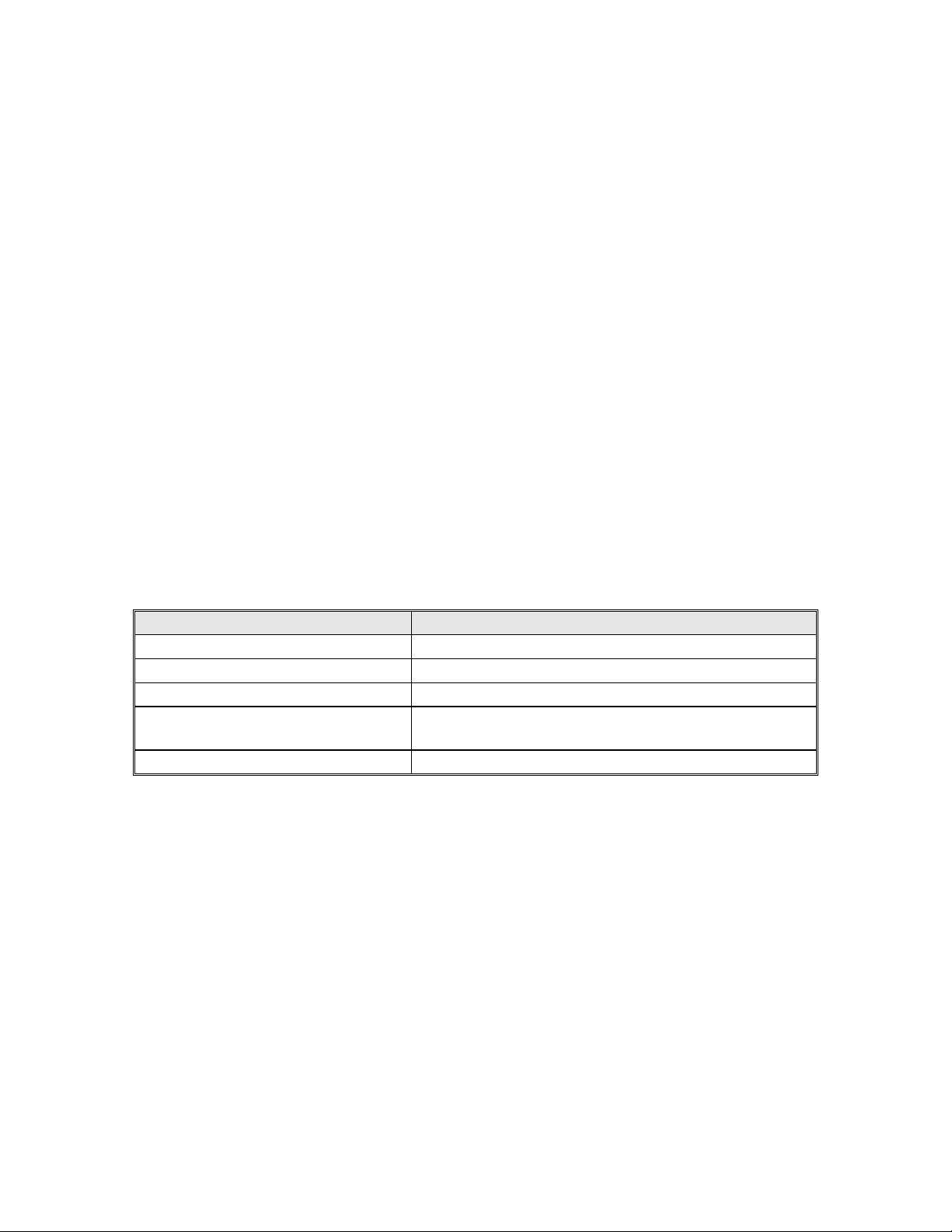
Display
Error Content
Unknown (at power-on)
CPU failure
“Err” (at power-on)
Calibration abnormal
Flashing “Err” (at power-on)
RAM or ROM failure
Flashing “Err” (during operation)
A/D converter failure, RJC failure, or EEPROM
failure
000 or b.o
Open thermocouple
Troubleshooting
Equipment that operates for long periods may develop problems. The DES2000 was
designed to have minimal problems; however, if there are problems please do the
following:
1. Have a qualified maintenance person verify wiring is correct.
2. Check the tuning and configuration parameters.
3. Verify that the thermocouple is working properly.
4. If everything is set up correctly, contact the Despatch Help Line at 800-473-7373
for assistance.
Table 7 Error Displays and Content
Page 18
12
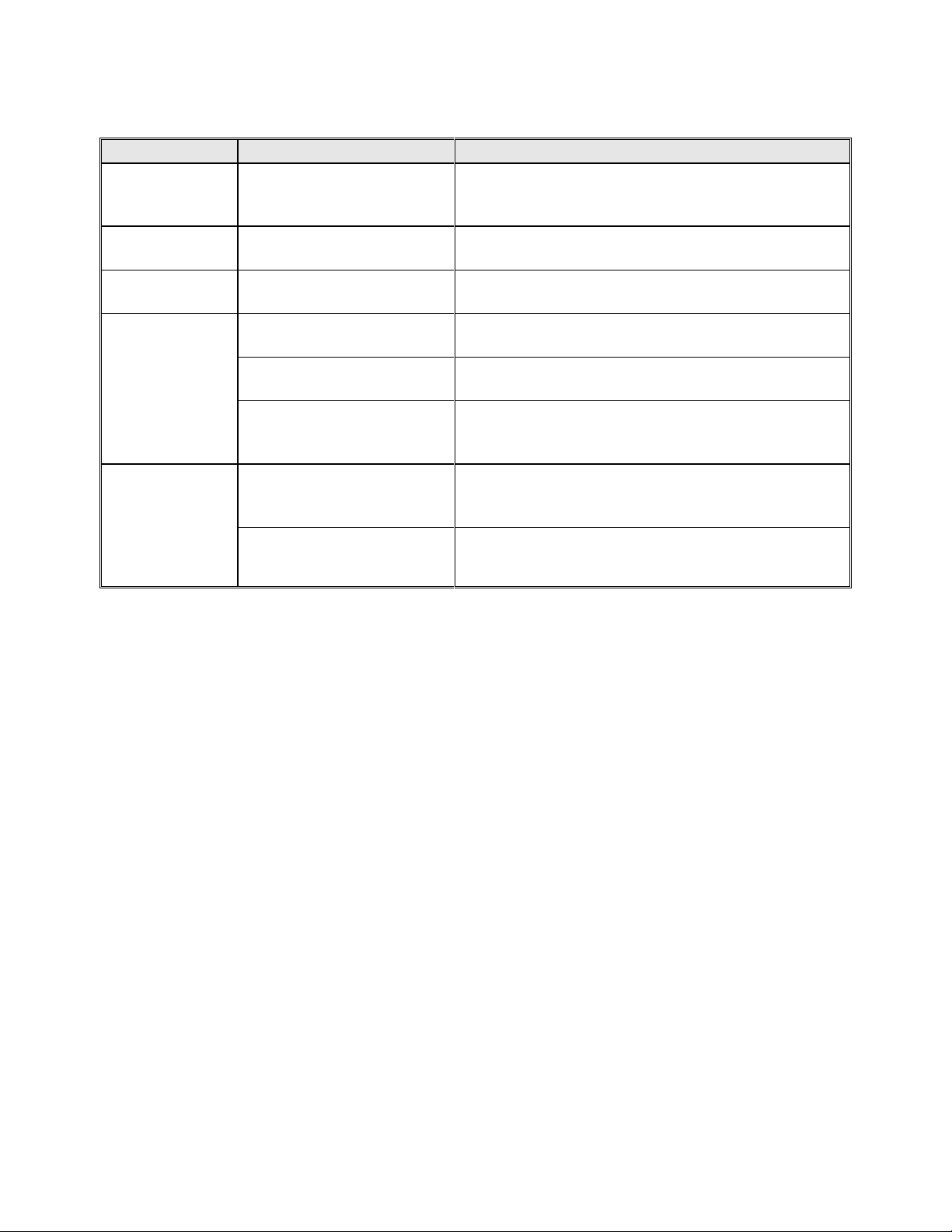
Table 8 Difficulties, Probable Causes, and Remedies
Difficulty
Probable cause
Suggested Remedy
Failure to heat
CONTROL instrument
malfunction
Check parameter in controller or replace
controller if OUT LED on controller does not turn
on.
Erratic
temperature
CONTROL instrument
malfunction
Check control parameters before replacing the
CONTROL instrument.
Inaccurate
temperature
CONTROL instrument
miscalibration
Recalibrate CONTROL instrument.
Oven will not
control at
setpoint
HI-LIMIT instrument set
too low
Set the HI-LIMIT higher.
CONTROL instrument
malfunction
Check control parameters before replacing
CONTROL instrument.
Air friction of recirculation
fan
Open exhaust air vent. Unit will not control at
minimum operating temperature with vent(s)
closed.
Heater does
not shutdown
until temp.
reaches the
HI-LIMIT
setting
CONTROL instrument
malfunction
Verify control parameters. Replace relay if no
output exists. Replace CONTROL instrument if
5VDC output exists.
SSR Relay malfunction
Replace relay if no CONTROL output exists.
Page 19

13
Technical Specifications
UL, cUL listed:
UL file E136675
CE compliance to:
EN55011: Class A, Group 1 for EMI (emission)
EN55082-2: 1995 for EMS (immunity)
Power supply:
100 to 240 VAC + 10% -15%, 50-60 Hz 8VA Maximum
Temperature:
Storage -25º to 60º C
Operating 0º to 50º C
Humidity:
5% to 90% RH (no condensation allowed)
Sensor inputs:
Universal
Input: 1 point
Sampling period 500 ms
Applicable standards
Thermocouple and resistance temperature detector
JIS/IEC/DIN ITS90
Temperature
display:
1º resolution (C or F)
Accuracy after calibration of +/- 1º C, or +/- 0.2º of sensed
temperature (whichever is greater) @25º C
Three digit seven segment LED, 0.75 inches high
Heat control output:
SSR Drive 24VDC nominal @ 40 ma
Front panel:
NEMA 4X (with gasket)
Dimensions:
1.87H x 1.87W x 3.25D inches
Panel opening:
1.77H x 1.77W inches
 Loading...