


 Loading...
PROPANE CONSTRUCTION CONVECTION HEATER
OWNER’S MANUAL
200 |
,000 |
|
BTU/HR
VARIABLE 40-80,000 BTU/HR
75-200,000 BTU/HR
IMPORTANT: Read and understand this manual before assembling, starting or servicing heater. Improper use of heater can cause serious injury. Keep this manual for future reference.
 GENERAL HAZARD WARNING:
Failure to comply with the precautions and instructions provided with this heater, can result in death, serious bodily injury and property loss or damage from hazards of fire, explosion, burn, asphyxiation, carbon monoxide poisoning and/or electrical shock.
Onlypersonswhocanunderstandandfollowtheinstructions should use or service this heater.
Ifyouneedassistanceorheaterinformationsuchasaninstructions manual, labels, etc. contact the manufacturer.
TABLE OF CONTENTS
Safety Information ............................................... |
2 |
Maintenance........................................................ |
7 |
Unpacking ........................................................... |
3 |
Troubleshooting................................................... |
8 |
Theory of Operation ............................................ |
3 |
Specifications ...................................................... |
9 |
Product Identification........................................... |
3 |
Replacement Parts.............................................. |
9 |
Ventilation ........................................................... |
3 |
Technical Services............................................... |
9 |
Propane Supply................................................... |
4 |
Accessories......................................................... |
9 |
Installation ........................................................... |
4 |
Illustrated Parts Breakdown and Parts List ....... |
10 |
Operation............................................................. |
5 |
Warranty and Repair Service ............................ |
14 |
Storage................................................................ |
7 |
|
|
Save this manual for future reference.
For more information, visit www.desatech.com

SAFETY INFORMATION
 WARNING: This product contains and/or generates chemicals known to the State of California to cause cancer or birth defects or other reproductive harm.
 WARNING: Fire, burn inhalation and explosion hazard. Keep solid combustibles, such as building materials, paper or cardboard,asafedistanceaway fromtheheaterasrecommended by the instructions. Never use theheaterinspaceswhichdoor may contain volatile or airborne combustibles or products such asgasoline,solvents,paintthinner, dust particles or unknown chemicals.
 WARNING: Not for home or recreational vehicle use.
The heater is designed for use as a construction heater in accordance with ANSI Z83.7•CGA 2.14. Other standards govern the use of fuel gases and heating products for specific uses. Your local authority can advise you about these. The primary purpose of construction heaters is to provide temporary heating of buildings under construction, alteration or repair. Properly used, the heater provides safe economical heating. Products of combustion are vented into the area being heated.
We cannot foresee every use which may be made of our heaters. CHECK WITH YOUR LOCAL
FIRE SAFETYAUTHORITY IFYOU HAVE QUESTIONS ABOUT HEATER USE.
Other standards govern the use of fuel gases and heat producing products for specific uses. Your local authorities can advise you about these.
Carbon Monoxide Poisoning: Some people are more affected by carbon monoxide than others. Early signs of carbon monoxide poisoning resemble the flu, with headaches, dizziness and/or nausea. If you have these signs, the heater may not beworkingproperly.Getfreshairatonce!Check for proper ventilation and have heater serviced.
Propane Gas: Propane gas is odorless. An odormaking agent is added to propane gas. The odor helps you detect a propane gas leak. However, the odor added to propane gas may fade. Propane gas may be present even though no odor exists.
Make certain you read and understand all warnings. Keep this manual for reference. It is your guide to safe and proper operation of this heater.
1.Install and use heater with care. Follow all local ordinances and codes. In the absence of local ordinances and codes, refer to the Standard for Storage and Handling of Liquefied Petroleum Gas, ANSI/NFPA 58 Natural Gas Installation Code, CAN/CGA B149.2. This instructs on the safe storage and handling of propane gases.
2.This product has been approved for use in the Commonwealth of Massachusetts.
3.Use only propane gas set up for vapor withdrawal.
4.Provide adequate ventilation. Before using heater, provide at least a 2.5 square foot (0.232 m2) (80,000 btu heaters) or 6.0 square foot (0.557 m2) (200,000 btu heaters) opening of fresh, outside air.
5.For indoor use only. Do not use heater outdoors.
6.Keep heater away from strong drafts, wind, water spray, rain or dripping water.
7.Do not use heater in occupied dwellings or in living or sleeping quarters.
8.Do not use heater in a basement or below ground level. Propane gas is heavier than air. If a leak occurs, propane gas may sink to the lowest possible level.
9.Keep appliance area clear and free from combustible materials, gasoline, paint thinner and other flammable vapors and liquids. Dust is combustible. Do not use heater in areas with high dust content.
10.Minimum heater clearances from combustibles:
80,000 Btu heaters
Sides: 3 feet (91 cm); Top: 6 feet (1.83 m)
100-200,000 Btu heaters
Sides: 3 feet (91 cm); Top: 7 feet (2.1 m)
11.Keep heater at least six feet (1.83 m) from propane tank(s).
12.Keep propane tank(s) below 100° F (37.8° C).
13.Use only the hose and factory preset regulator provided with the heater.
14.Check heater for damage before each use. Do not use a damaged heater.
2 |
www.desatech.com |
116557-01A |
SAFETY INFORMATION
Continued
15.Checkhosebeforeeachuseofheater.Ifhighly worn or cut, replace with hose specified by manufacturer before using heater.
16.Do not alter heater. Keep heater in its original state.
17.Do not use heater if altered.
18.Locate heater on stable and level surface if heater is hot or operating.
19.Not intended for use on finished floors.
20.Never block air inlet (bottom of shell) or air outlet (around top of shell) of heater.
21.Do not leave heater unattended.
22.Keep children and animals away from heater.
23.Never move, handleor service a hot or operating heater. Severe burns may result.You must wait 15 minutes after turning heater off.
24.To prevent injury, wear gloves when handling heater.
25.Never attach duct work to heater.
26.Turn off propane supply to heater when not in use.
27.Use only original replacement parts. This heater must use design-specific parts. Do not substitute or use generic parts. Improper replacement parts could cause serious or fatal injuries.
UNPACKING
1.Removeallpackingitemsappliedtoheaterfor shipment.Keepplasticcovercaps(attachedto inlet connector and hose/regulator assembly) for storage.
2.Remove all items from carton.
3.Check all items for shipping damage. If heater isdamaged,promptlyinformdealerwhereyou bought heater.
THEORY OF OPERATION
The Fuel System: The hose/regulator assembly attaches to the propane gas supply. This provides fuel to the heater.
The Ignition System: The piezo ignitor lights the pilot.
TheAutomaticControlSystem:Thissystemcauses the heater to shut down if the flame goes out.
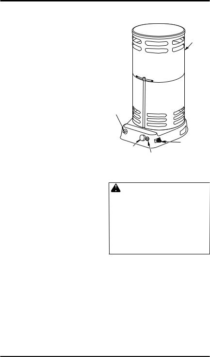
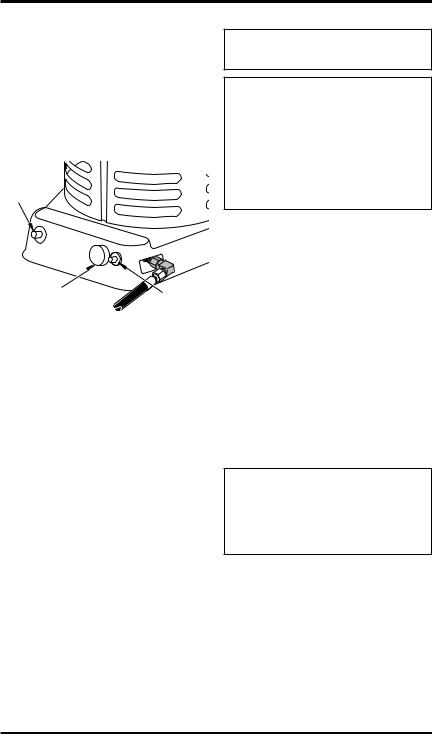
PRODUCT
IDENTIFICATION
Outer
Shell
Ignitor
Button
200 |
,000 |
|
|
|
|
BTU |
|
|
|
|
|
|
|
|
|
|
/HR |
|
|
Ball Valve |
|
|
Valve |
|
|
|
Inlet |
|
|
Control Knob |
Safety Pilot |
Valve |
|
|
Button |
|
|
||
|
|
|
|
|
Figure 1 - 200,000 Btu Model Shown |
|
|||
VENTILATION |
|
|||
WARNING: Provide at least |
||||
a 2.5 square foot |
(0.23 m |
) |
||
|
|
|
2 |
|
opening of fresh, outside air |
||||
while running heater. If proper |
||||
fresh, outside air ventilation is |
||||
not provided, carbon monoxide |
||||
poisoning can occur. Provide |
||||
properfresh,outsideairventila- |
||||
tion before running heater. |
|
|||
116557-01A |
www.desatech.com |
3 |
PROPANE SUPPLY You must provide propane gas and propane tank(s).
Use this heater only with a propane vapor withdrawal supply system. See Chapter 5 of the Standard for Storage and Handling of Liquefied Petroleum Gas, ANSI/NFPA 58 and/or CAN/CGA B149.2. Your local library or fire department will have this booklet.
This heater will operate with a 20 pound (9.07 kg) propane tank. However, you can only operate it in the LOW position during mildly cool weather for a very short time.At higher heat settings or during colder weather, you must use larger tanks.
The amount of propane gas ready for use from propane tanks varies. Two factors decide this amount.
1.The amount of propane gas in tank(s)
2.The temperature of tank(s)
The chart below shows the minimum number of |
|
100 pound (45 kg) tanks needed to run the heater. |
|
Connect tanks together with a manifold. |
|
Average Temperature |
Number |
At Tank Location |
Of Tanks |
(80,000 Btu models) |
|
20° F (-6.7° C) to 60° F (15.6° C) |
1 |
0° F (-17.8° C) to 20° F (-6.7° C) |
2 |
(200,000 Btu models) |
|
20° F (-6.7° C) to 60° F (15.6° C) |
2 |
0° F (-17.8° C) to 20° F (-6.7° C) |
3 |
Less gas is vaporized at lower temperatures.Your |
|
local propane gas dealer will help you select the |
|
proper supply system. |
|
INSTALLATION |
|
|
|
WARNING: Review and un- |
|
derstand the warnings in the |
|
SafetyInformationsection,page |
|
2. They are needed to safely op- |
|
eratethisheater.Followalllocal |
|
codes when using this heater. |
|
|
|
CAUTION: Never ignite and/ |
|
or run this heater unless the |
|
shells are fully extended and |
|
locked into position. |
|
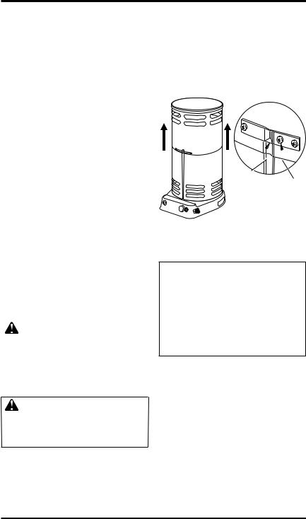
OUTER SHELL |
|
IMPORTANT: When the heater is first removed |
|
from carton, the outer shell is in the down posi- |
|
tion.Protecthandsbeforeliftingoutershell.Never |
|
grasp bare metal without hand protection. |
|
1.Care must be taken to protect hands during this step.LiftoutershellstraightupasshowninFigure 2, until all three clips engage slots in lower shell. Screw holes will line up at this point.
2.Lock clips into place with 3 screws as shown in Figure 2. The heater must not be operated unless the outer shell is properly extended and fully locked into place.
Outer
 Shell
Shell
2 |
|
00,00 |
0BT |
|
|
|
U/HR |
Clip in Slot
of Lower
Shell
3 Screws per Clip
Figure 2 - Lifting Outer Shell
(200,000 Btu Model Shown)
CONNECTING TO GAS SUPPLY
 WARNING:Testallgaspiping and connections for leaks after installation or servicing. Never use an open flame to check for a leak. Apply a mixture of liquid soap and water to all joints. Bubbles forming show a leak. Correct all leaks at once.
1.Provide propane supply system (see Propane Supply).
2.Connect fuel gas fitting on hose/regulator assembly to propane tank(s). Turn fuel gas fitting counterclockwise into threads on tank. Tighten firmly using a wrench. IMPORTANT: Tighten regulator with vent pointing down. Pointing vent down protects regulator from weather damage.
3.Connect hose to the valve inlet. Tighten firmly usingawrench.Youmustusetheregulatorsupplied with heater even if propane tank has one.
4 |
www.desatech.com |
116557-01A |
INSTALLATION
Continued
4.Openpropanesupplyvalveonpropanetank(s) slowly. Note: If not opened slowly, excessflow check valve on propane tank may stop gas flow. If this happens, you may hear a click inside the regulator assembly, this is the check valve closing. To reset the excess flow check valve, close propane supply valve and open again slowly.
5.Check all connections for leaks. Apply mixture of liquid soap and water to gas joints. Bubbles forming show a leak that must be corrected.
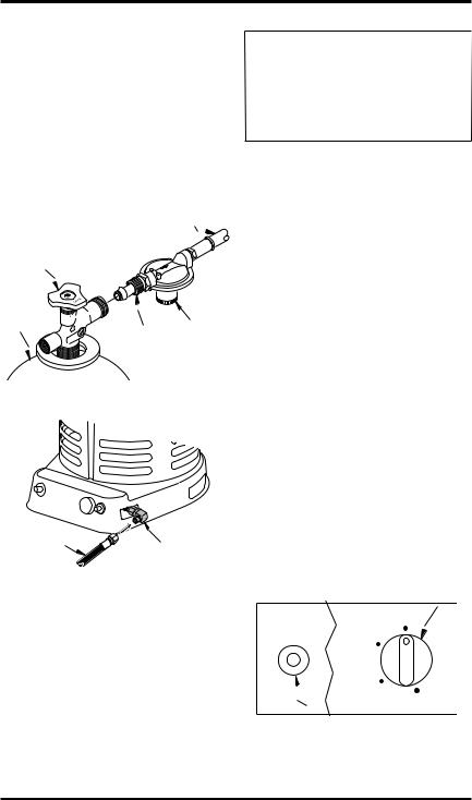
|
Hose |
Propane Supply |
|
Valve |
|
Propane |
|
Tank |
Regulator |
|
|
|
POL |
|
Fitting |
Figure 3 - Regulator Position |
|
Hose |
Valve Inlet |
|
|
Figure 4 - Hose and Valve Inlet |
|
(200,000 Btu Model Shown) |
|
OPERATION
 WARNING: Review and understand the warnings in the SafetyInformationsection,page 2. They are needed to safely operatethisheater.Followalllocal codes when using this heater.
80,000 BTU HEATER TO START HEATER
1.Follow all installation, ventilation and safety information.
2.Locateheateronstableandlevelsurface.Make sure strong drafts do not blow on heater.
3.Make sure unit is turned off by slightly depressing and turning control knob fully clockwise to OFF.
4.Openpropanesupplyvalveonpropanetank(s) slowly. Note: If not opened slowly, excessflow check valve on propane tank may stop gas flow. If this happens, you may hear a click inside the regulator assembly, this is the check valve closing. To reset the excess flow check valve, close propane supply valve and open again slowly.
5.Slightly depress and turn control knob counterclockwise to the LO position (see Figure 5).
6.With the control knob pushed all the way in, press and release the piezo ignitor button. Keep pressing piezo ignitor button until the burner lights. Hold control knob down for a maximum of 15 seconds while attempting ignition.Ifheaterdoesnotignite,releasecontrol knob and wait 3 minutes before attempting reignition.
7.After ignition, hold control knob down for about30seconds.Thisactivatestheautomatic control system.
|
Control Knob |
|
Off/ |
|
Apagado/ |
|
Arrêt |
Lo/Baja/ |
|
Basse |
|
Med/ |
|
Media/ |
|
Moyenne |
Hi/Alta/ |
|
|
|
Haute |
Piezo Ignitor Button |
|
Figure 5 - Control Knob and Piezo Ignitor |
|
116557-01A |
www.desatech.com |
5 |
OPERATION
Continued
8.Whenburnerremainslit,setheateratthedesired heatlevelbyslightlydepressingthecontrolknob and turning it counterclockwise to the MED or HI settings (see Figure 5, page 5).
9.Ifburnergoesout,turnoffgas.Slightlydepress and turn control knob fully clockwise to OFF. Checkfuelsupply.Ifadequatefuelisavailable, restart heater beginning at step 1, page 5.
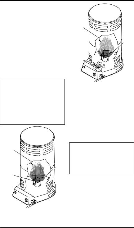
FLAME PATTERNS
Figure 6 shows a correct flame pattern.The burner flame is mostly blue with a slight yellow coloring on the ends.
Figure 7 shows an incorrect flame pattern. The flameismostlyyellow.Theincorrectflamepattern results from low gas pressure or from flashback.
 CAUTION: Running heater belowspecifiedinputratingmay cause flashback. During flashback,theburnerflameismostly yellow.Theflamewillburninside the burner tube, causing a roaring noise. If flashback occurs, turnheateroff.Afterburnertube cools, restart the heater.
Slight Yellow
Coloring on
Flame Ends
Blue
Flame
Burner
Tube
Figure 6 - Correct Flame Pattern at High
Position
Yellow
Flame
Blue
Flame
Flame Inside Burner Tube (makes roaring noise)
Figure 7 - Incorrect Flame Pattern During
Flashback
TO STOP HEATER
1.Tightlyclosepropanesupplyvalveonpropane tank(s). Allow heater to burn remaining fuel in hose.
2.Shut off burner. Do this by pushing in the controlknobandturningclockwisetotheOFF position.
TO RESTART HEATER
1.Wait five minutes after stopping heater.
2.Restart heater by following To Start Heater, page 5.
 WARNING: Review and understand the warnings in the
SafetyInformationsection,page 2. They are needed to safely operatethisheater.Followalllocal codes when using this heater.
200,000 BTU/HR HEATER TO START HEATER
1.Before lighting pilot fully close the ball valve (turn knob fully clockwise).
2.Fullyopenthevalveonthepropanecylinderand wait 15 seconds before proceeding to step 3.
3.Depressredbuttononsafetypilotvalveadmitting gas to the heater. Then push and release the ignitor button until the pilot lights.
6 |
www.desatech.com |
116557-01A |
OPERATION
Continued
4.Whenthepilotlights,continuetoholdthebutton depressed for 30 seconds, then release.
5.If pilot goes out, wait 5 minutes and repeat the lighting procedure.
6.When the pilot remains lit, open the ball valve (turn knob counterclockwise) to light main burner. Partially close valve to regulate heat output.
Ignitor
Button
Ball Valve Control |
Safety Pilot |
|
Knob Button |
||
Valve |
||
|
||
Figure 8 - Starting Heater |
||
TO STOP HEATER |
|
|
1.Securely close valve on the propane cylinder.
2.Continue to operate heater until all fuel in the hose has burned.
3.Fully close the ball valve.
TO RESTART HEATER
1.Securely close valve at propane cylinder.
2.Wait 5 minutes.
3.Restart heater by following To Start Heater, page 6.
STORAGE
 CAUTION:Disconnectheater
from propane supply tank(s).
 CAUTION: Be careful not to locate fingers in groves on side of heater, in vent holes or on bottom of shell when collapsing shell to the down position. Severe cuts may occur. Always wear hand protection when grasping bare metal.
1.Theheatershouldbeinspectedbeforeeachuse and at least annually by a qualified person.
2.Beforeeachuse,checkthesoft"O"ringseatat the bullnose of the POLfitting. If the "O" ring is cut, scuffed or otherwise damaged, replace the POL fitting with part number LPA4020.
3.Turn off the gas at the propane/LP gas supply cylinder(s) when the heater is not in use.
4.Heater is to be stored indoors.The connection between propane/LP gas supply cylinder(s) and heater must be disconnected, cylinder(s) removed from the heater and stored outdoors in accordance with Chapter 5 of the Standard for Storage and Handling of Liquefied Petroleum Gases ANSI/NFPA 58 and CSA B149.1, Natural Gas and Propane Installation Code.
5.Store in a dry, clean and safe place.
MAINTENANCE
 WARNING: Never attempt to service heater while it is connected to propane supply, operating or hot. Severe burns can occur.
1.Keep heater clean.
2.Inspect heater before each use. Check connections for leaks. Apply mixture of liquid soap and water to connections. Bubbles forming show a leak that must be corrected. Correct all leaks at once.
3.Inspect hose/regulator assembly before each use. If hose is highly worn or cut, replace.
4.Have heater inspected yearly by a qualified service person.
116557-01A |
www.desatech.com |
7 |

TROUBLESHOOTING
 WARNING:Neverserviceheaterwhileitispluggedin,connected to propane supply, operating or hot. Severe burns and electrical shock can occur.
OBSERVED FAULT |
POSSIBLE CAUSE |
REMEDY |
||
|
|
|
|
|
Burner fails to light |
1. Propane supply valve closed |
1. |
Open propane supply valve |
|
|
|
on propane tank(s) |
|
slowly |
|
2. |
Excess flow check valve |
2. |
Close propane supply valve |
|
|
closed |
|
on propane tank and reopen |
|
3. |
Blockage in burner orifice |
|
slowly |
|
3. |
Replace burner orifice |
||
|
4. |
Piezo ignition system not |
4. |
Check to assure ignitor elec- |
|
|
sparking |
|
trode gap is .195" Check wire |
|
|
|
|
lead for damage. Replace |
|
|
|
|
piezo ignitor and/or ignitor |
|
5. |
Pilot orifice clogged |
|
electrode as necessary |
|
5. |
Clean or replace pilot assembly |
||
|
|
(200,000 Btu models only) |
|
|
|
|
|
|
|
Pilot lights but goes out when |
1. Not enough warm up time |
1. |
Relight,holdautomaticcontrol |
|
automatic control valve button |
2. Low gas pressure |
|
valve button in 45 seconds |
|
is released (200,000 Btu models |
2. |
Check propane tank(s) for |
||
only) |
3. |
Thermocouple loose or needs |
|
proper gas supply |
|
3. |
Tighten connection or replace |
||
|
|
to be replaced |
|
thermocouple |
|
4. |
Automaticcontrolvalveneeds |
4. |
Replace automatic control |
|
|
to be replaced |
|
valve |
|
|
|
|
|
Burn rate is low |
1. Control valve is on LOW |
1. |
Turn valve counter clockwise |
|
|
2. |
Plugged gas orifice |
|
to HIGH |
|
2. |
Replace gas orifice |
||
|
3. |
Low gas pressure |
3. |
Check gas supply; check |
|
4. |
Low fuel supply |
|
regulator output |
|
4. |
Consult propane gas supplier |
||
8 |
www.desatech.com |
116557-01A |

SPECIFICATIONS
|
80,000 Btu |
200,000 Btu |
Type of Gas |
Propane/LP Only |
Propane/LP Only |
Gas Supply Pressure to regulator |
|
|
Maximum |
Bottle Pressure |
Bottle Pressure |
Minimum |
5 psig (34.5 kPa) |
15 psig (103 kPa) |
Gas Supply Pressure regulator out |
25" W.C. (63.5 cm) |
10 psig (68.9 kPa) |
Ignition |
Piezo Ignitor |
Piezo Ignitor |
Minimum Ambient Temp. Rating |
0° F (-17.8° C) |
0° F (-17.8° C) |
Rating |
40,000 - 80,000 Btu/hr |
75,000 - 200,000 Btu/hr |
|
(11.72 - 23.4 kW) |
(22.0 - 58.6 kW) |
Fuel Consumption |
1.85 - 3.71 lb/hr |
3.48 - 9.28 lb/hr |
|
(0.83 – 1.68 kg/hr) |
(1.58 - 4.21 kg/hr) |
Fuel Orifice Port No. |
1 |
6 |
Fuel Orifice Port Size |
0.086" |
0.0320" |
|
(2.18 mm) |
(.813 mm) |
REPLACEMENT PARTS
 WARNING:Useonlyoriginal replacement parts. This heater must use design-specific parts.
Donotsubstituteorusegeneric parts. Improper replacement parts could cause serious or fatalinjuries.Thiswillalsoprotect yourwarrantycoverageforparts replaced under warranty.
PARTS UNDER WARRANTY
Contact authorized dealers of this product. If they canʼt supply original replacement part(s), either contact your nearest Parts Central or call DESA Heating Productsʼ Technical Service Department at 1-866-672-6040.
When calling DESAHeating Products, have ready
•your name
•your address
•model number of your heater
•how heater was malfunctioning
•purchase date
PARTS NOT UNDER WARRANTY
Contact authorized dealers of this product. If they canʼt supply original replacement part(s), either contact your nearest Parts Central (listed in Authorized Service Center booklet) or call DESA Heating Products at 1-866-672-6040 for referral information.
When calling DESAHeating Products, have ready
•model number of your heater
•the replacement part number
TECHNICAL SERVICES
You may have further questions about this heater. If so, contact DESA Heating ProductsʼTechnical Service Department at 1-866-672-6040. When calling,pleasehaveyourmodelandserialnumbers of your heater ready.
YoucanalsovisitDESAHeatingProductsʼTechnical Service web site at www.desatech.com.
ACCESSORIES
Purchase heater accessories and parts from your nearest dealer or service center. If they can not supply an accessory or part, either contact your nearest Parts Central (listed in the separate Authorized Service Center booklet) or call DESA Heating Productsʼ at 1-866-672-6040. You can also write to the address listed on the back page of this manual.
116557-01A |
www.desatech.com |
9 |
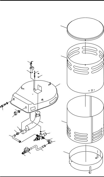
ILLUSTRATED PARTS BREAKDOWN
MODELS
80-CC, RCP80VC, REMCP80VC, SPC-80CC AND TC80VC
11
10
12
13
14
15
1
2
6
7  8
8
9
5
3
16
17
18
19
20
21 4
23 22
10 |
www.desatech.com |
116557-01A |
PARTS LIST
MODELS
80-CC, RCP80VC, REMCP80VC, SPC-80CC AND TC80VC
This list contains replaceable parts used in your heater. When ordering parts, follow the instructions listed under Replacement Parts on page 9 of this manual.
KEY |
PART |
|
|
NO. |
NUMBER |
DESCRIPTION |
QTY. |
1 |
113785-01 |
Cap |
1 |
2 |
113781-01 |
Upper Shell |
1 |
3 |
113825-01 |
Lower Shell |
1 |
4 |
113778-01 |
Ring Shield |
1 |
5 |
** |
Base |
1 |
6 |
116617-01 |
Ignitor Electrode |
1 |
7 |
103854-01 |
Thermocouple Bracket |
1 |
8 |
113790-01 |
Thermocouple |
1 |
9 |
100898-01 |
Thin Hex Nut |
2 |
10 |
102445-01 |
Piezo Ignitor Kit |
1 |
11 |
098508-01 |
Valve Retainer Nut |
1 |
12 |
099393-03 |
Control Knob |
1 |
13 |
103037-03 |
Nozzle Locator |
1 |
14 |
116556-01 |
Nozzle |
1 |
15 |
116570-01 |
Fuel Tube Kit |
1 |
16 |
103929-01 |
Burner Tube Kit |
1 |
17 |
099460-01 |
Brass Hex Cap |
1 |
18 |
116554-01 |
Automatic Valve |
1 |
19 |
113812-02 |
Adapter, 1/4 FPT x 1/4 MPT |
1 |
20 |
113795-01 |
Female Elbow Fitting, 1/4 FPT x 3/8 FLR |
1 |
21 |
113776-01 |
Hose Assembly, 10 foot |
1 |
22 |
113862-01 |
Regulator |
1 |
23 |
113791-01 |
POL, Excess Flow |
1 |
|
|
|
|
|
|
PARTS AVAILABLE - NOT SHOWN |
|
|
113822-11 |
Tradename Decal, Reddy |
1 |
|
113822-12 |
Tradename Decal, Master |
1 |
|
113822-13 |
Tradename Decal, All-Pro |
1 |
|
113822-14 |
Tradename Decal, Universal |
1 |
|
113822-09 |
Tradename Decal, Remington |
1 |
|
113808-07 |
Hang Tag (English) |
1 |
|
113808-08 |
Hang Tag (Spanish) |
1 |
|
113808-09 |
Hang Tag (French) |
1 |
|
113805-04 |
Installation Decal (English) |
1 |
|
113805-05 |
Installation Decal (Spanish) |
1 |
|
113805-06 |
Installation Decal (French) |
1 |
|
113802-17 |
Model Decal |
1 |
|
116558-01 |
Control Position Decal |
1 |
|
|
|
|
**Not a field replaceable part
116557-01A |
www.desatech.com |
11 |

ILLUSTRATED PARTS BREAKDOWN
MODELS
200C, RCP200V(A), SPC-200C AND TC200V(A)
|
|
|
10 |
9 |
1 |
25 |
8 |
|
|
|
17 |
|
27 |
24 |
29 |
|
|
|
13 |
|
|
|
|
|
|
23 |
6 |
5 |
|
23
15
16
20
14 |
31 |
|
22 |
||
|
||
28 |
|
21
19 2
18
12
7
30
3
4
26
12 |
www.desatech.com |
116557-01A |

PARTS LIST
MODELS
200C, RCP200V(A), SPC-200C AND TC200V(A)
This list contains replaceable parts used in your heater. When ordering parts, follow the instructions listed under Replacement Parts on page 9 of this manual.
KEY |
PART |
|
|
NO. |
NUMBER |
DESCRIPTION |
QTY. |
|
|
|
|
1 |
113814-01 |
Pilot Assembly |
1 |
2 |
113815-01 |
Hose Assembly, 10 foot |
1 |
3 |
113777-01 |
Burner Ring Assembly |
1 |
4 |
113778-01 |
Ring Shield |
1 |
5 |
113779-01 |
Fuel Tube Assembly |
1 |
6 |
113780-01 |
Pilot Tube Assembly |
1 |
7 |
113781-01 |
Upper Shell |
1 |
8 |
113782-01 |
Orifice Adapter |
1 |
9 |
113783-01 |
Bracket, Pilot Mounting |
1 |
10 |
113816-01 |
Orifice, LP |
1 |
11 |
** |
Base |
1 |
12 |
113875-01 |
Cap |
1 |
13 |
113876-01 |
Thermocouple Clip |
1 |
14 |
113787-01 |
Control Valve |
1 |
15 |
113788-01 |
Female Elbow Fitting, 1/4 FLR x 1/8 FPT |
1 |
16 |
113789-01 |
Female Elbow Fitting, 1/4 FLR x 1/4 FPT |
1 |
17 |
113790-01 |
Thermocouple |
1 |
18 |
113818-01 |
POL, Excess Flow |
1 |
19 |
113819-01 |
Regulator |
1 |
20 |
113793-01 |
Ball Valve |
1 |
21 |
102445-01 |
Piezo Ignitor |
1 |
22 |
113794-01 |
Valve Nut, 1/2-28 |
1 |
23 |
113795-01 |
Female Elbow Fitting, 1/4 FPT x 3/8 FLR |
3 |
24 |
113796-01 |
Retaining Ring |
1 |
25 |
113797-01 |
Ignitor Electrode |
1 |
26 |
113798-01 |
Heat Shield |
1 |
27 |
113799-01 |
Pilot Orifice |
1 |
28 |
113800-01 |
Washer, Flat |
1 |
29 |
113801-01 |
Elbow Fitting, 1/8 FPT x 1/4 CPSN |
1 |
30 |
113821-01 |
Lower Shell |
1 |
31 |
113812-01 |
Fitting, 1/4 FPT x 1/4 MPT |
1 |
|
|
|
|
|
|
PARTS AVAILABLE - NOT SHOWN |
|
|
113809-01 |
Ball Valve Knob |
1 |
|
113810-01 |
Ball Valve Knob Insert |
1 |
|
113822-03 |
Tradename Decal, Reddy |
1 |
|
113822-04 |
Tradename Decal, Master |
1 |
|
113822-07 |
Tradename Decal, All-Pro |
1 |
|
113822-08 |
Tradename Decal, Universal |
1 |
|
113822-10 |
Tradename Decal, Remington |
1 |
|
113808-01 |
Hang Tag (English) |
1 |
|
113808-02 |
Hang Tag (Spanish) |
1 |
|
113808-03 |
Hang Tag (French) |
1 |
|
113805-01 |
Installation Decal (English) |
1 |
|
113805-02 |
Installation Decal (Spanish) |
1 |
|
113805-03 |
Installation Decal (French) |
1 |
|
113802-18 |
Model Decal |
1 |
**Not a field replaceable part
116557-01A |
www.desatech.com |
13 |
WARRANTY AND REPAIR SERVICE
KEEP THIS WARRANTY
Model
Serial No.
Date of Purchase
LIMITED WARRANTIES FOR NEW AND FACTORY
RECONDITIONED PRODUCTS
New Products: DESAHeating Products warrants this heater and any parts thereof, to be free of defects in materials and workmanship for one (1) year from the date of first purchase, when operated and maintained in accordance with the manufacturer's instructions. These warranties are extended only to the original retail purchaser, when proof of purchase is provided.
Factory Reconditioned Heaters: DESAHeating Products warrants this factory reconditioned heater and any parts thereof, to be free of defects in materials and workmanship for thirty (30) days from the date of first purchase, when operated and maintained in accordance with the manufacturer's instructions. These warranties are extended only to the original retail purchaser, when proof of purchase is provided.
These warranties cover only the cost of parts and labor required to restore the product to proper operating condition. Transportation and incidental costs associated with warranty repairs are not reimbursable under this warranty.
Warranty service is available only through authorized dealers and service centers.
Thiswarrantydoesnotcoverdefectsresultingfrommisuse,abuse,negligence,accidents,lackofpropermaintenance, normalwear,alteration,modification,tampering,contaminatedfuels,repairusingimproperpartsorrepairbyanyone other than an authorized dealer or service center. Routine maintenance is the responsibility of the owner.
THIS EXPRESS WARRANTY IS GIVEN IN LIEU OF ANY OTHER WARRANTY EITHER EXPRESSED OR IMPLIED, INCLUDINGWARRANTIES OF MERCHANTABILITYAND FITNESS FORAPARTICULAR PURPOSE.
DESAHeating Products assumes no responsibility for indirect, incidental or consequential damages. Some states do not allow the exclusion or limitation of incidental or consequential damages or limitations or exclusions may not apply to you. This limited warranty gives you specific legal rights and you may also have other rights which vary from province to province.
WARRANTY SERVICE
Should your heater require service, return it to your nearest authorized service center. Proof of purchase must be presented with the heater. The heater will be inspected. A defect may be caused by faulty materials or workmanship. If so, DESA Heating Products will repair or replace the heater without charge.
REPAIR SERVICE
Return the heater to your nearest authorized service center. Each Service Center is independently owned and operated. Repairs not covered by the warranty will be billed at standard prices.We reserve the right to amend these specifications at any time without notice.
Illustrated parts lists can be obtained free of charge. Send a self-addressed stamped envelope to the address listed below. List the heater model number and the date located in the lower right corner of this page. A service manual may be purchased from the address listed below. Send a check or money order for $5.00 (US) payable to DESA Heating Products.
When writing for information regarding your heater, be sure to include the model number and serial number as shown on the model plate.
2701 Industrial Drive |
2220 Argentia Road, Unit #4 |
|
Mississauga, Ontario L5N 2K7 |
||
P.O. Box 90004 |
||
(905) 826-8010 |
||
Bowling Green, KY 42102-9004 |
||
Fax (905) 826-8236 |
||
ATTN: Customer Service Department |
||
|
Loading...