


DESA INTERNATIONAL
UNVENTED (VENT-FREE) PROPANE/LP GAS FIREPLACE
This appliance may be installed in an aftermarket* manufactured (mobile) home, where not prohibited by state or local codes.
* Aftermarket: Completion of sale, not for purpose of resale, from the manufacturer
OWNER’S OPERATION AND INSTALLATION MANUAL
Variable
Manually-
Controlled
Models and
Thermostatically-
Controlled
“B” Models
with
Split Oak Logs
,,,,,,QQQQQQ¢¢¢¢¢¢ |
,,,,,,QQQQQQ¢¢¢¢¢¢ |
,,,,,,QQQQQQ¢¢¢¢¢¢ |
,,,,,,QQQQQQ¢¢¢¢¢¢ |
,,,,,,QQQQQQ¢¢¢¢¢¢ |
,,,,,,QQQQQQ¢¢¢¢¢¢ |
,Q¢,,,,,,QQQQQQ¢¢¢¢¢¢,,QQ¢¢ |
,,,,,,,,QQQQQQQQ¢¢¢¢¢¢¢¢,Q¢ |
®
Shown with optional cabinet mantel, hearth base, and trim accessories.
WARNING: If the information in this manual is not followed exactly, a fire or explosion may result causing property damage, personal injury, or loss of life.
—Do not store or use gasoline or other flammable vapors and liquids in the vicinity of this or any other appliance.
—WHAT TO DO IF YOU SMELL GAS
•Do not try to light any appliance.
•Do not touch any electrical switch; do not use any phone in your building.
•Immediately call your gas supplier from a neighbor’s phone. Follow the gas supplier’s instructions.
•If you cannot reach your gas supplier, call the fire department.
—Installation and service must be performed by a qualified installer, service agency, or the gas supplier.
WARNING: Improper installation, adjustment, alteration, service, or maintenance can cause injury or property damage. Refer to this manual for correct installation and operational procedures. For assistance or additional information consult a qualified installer, service agency, or the gas supplier.
WARNING: This is an unvented gas-fired heater. It uses air (oxygen) from the room in which it is installed. Provisions for adequate combustion and ventilation air must be provided. Refer to Air for Combustion and Ventilation section in this manual.
Save this manual for future reference.

CONTENTS
SAFETY INFORMATION
2
SECTION |
PAGE |
Safety Information .................................................................................................. |
2 |
Product Identification ............................................................................................. |
4 |
Local Codes ............................................................................................................ |
5 |
Unpacking ............................................................................................................... |
5 |
Product Features ..................................................................................................... |
5 |
Air for Combustion and Ventilation ....................................................................... |
6 |
Installing ................................................................................................................. |
9 |
Check Gas Type .............................................................................................. |
9 |
Electrical Hookup ............................................................................................ |
9 |
Assembling and Attaching Brass Trim ........................................................... |
10 |
Installation Clearances .................................................................................... |
11 |
Conventional Fireplace Installation ................................................................ |
11 |
Built-In Fireplace Installation ......................................................................... |
13 |
Installing Gas Piping to Fireplace Location .................................................... |
15 |
Connecting Fireplace to Gas Supply ............................................................... |
17 |
Checking Gas Connections ............................................................................. |
18 |
Installing Logs ................................................................................................. |
20 |
Operating Fireplace (Thermostat-Controlled Models) ........................................... |
22 |
Operating Fireplace (Manually-Controlled Models) .............................................. |
24 |
Inspecting Burners .................................................................................................. |
26 |
Cleaning and Maintenance ..................................................................................... |
28 |
Troubleshooting ...................................................................................................... |
28 |
Technical Service ................................................................................................... |
32 |
Service Hints .......................................................................................................... |
32 |
Replacement Parts .................................................................................................. |
32 |
Specifications ......................................................................................................... |
33 |
Wiring Diagram ...................................................................................................... |
33 |
Accessories ............................................................................................................. |
34 |
Illustrated Parts Lists .............................................................................................. |
36-43 |
Warranty Information ............................................................................................. |
Back Cover |
 WARNINGS
IMPORTANT: Read this owner’s manual carefully and completely before trying to assemble, operate, or service this fireplace. Improper use of this fireplace can cause serious injury or death from burns, fire, explosion, electrical shock, and carbon monoxide poisoning.
 DANGER
Carbon monoxide poisoning may lead to death!
Carbon Monoxide Poisoning: Early signs of carbon monoxide poisoning resemble the flu, with headaches, dizziness, or nausea. If you have these signs, the fireplace may not be working properly. Get fresh air at once! Have fireplace serviced. Some people are more affected by carbon monoxide than others. These include pregnant women, people with heart or lung disease or anemia, those under the influence of alcohol, and those at high altitudes.
Propane Gas: Propane gas is odorless. An odor-making agent is added to the gas. The odor helps you detect a gas leak. However, the odor added to the gas can fade. Gas may be present even though no odor exists.
Make certain you read and understand all Warnings. Keep this manual for reference. It is your guide to safe and proper operation of this fireplace.
Safety Information continues on next page
103415

SAFETY |
|
WARNING ICON G 001 WARNINGS Continued |
|
WARNING: Any change to this fireplace or its controls can be dangerous. |
|||
INFORMATION |
1. |
This appliance is only for use with the type of gas indicated on the rating plate. This |
|
|
|||
Continued |
|
appliance is not convertible for use with other gases. |
|
2. |
Do not place propane supply tank(s) inside any structure. Locate propane supply tank(s) |
||
|
|
outdoors. |
|
|
3. |
If you smell gas |
|
|
|
• shut off gas supply |
|
|
|
• do not try to light any appliance |
|
|
|
• do not touch any electrical switch; do not use any phone in your building |
|
|
|
• immediately call your gas supplier from a neighbor’s phone. Follow the gas |
|
|
|
supplier’s instructions |
|
|
|
• if you cannot reach your gas supplier, call the fire department |
|
|
4. |
This fireplace shall not be installed in a bedroom or bathroom. |
|
|
5. |
Never install the fireplace |
|
|
|
• in a recreational vehicle |
|
|
|
• where curtains, furniture, clothing, or other flammable objects are less than 36 |
|
|
|
inches from the front, top, or sides of the fireplace |
|
|
|
• in high traffic areas |
|
|
|
• in windy or drafty areas |
|
|
6. |
Do not use this fireplace as a wood-burning fireplace. Use only the logs provided with |
|
|
|
the fireplace. |
|
|
7. |
Do not add extra logs or ornaments such as pine cones, vermiculite, or rock wool. Using |
|
|
|
these added items can cause sooting. Do not add lava rock around base. Rock and debris |
|
|
|
could fall into the control area of fireplace. |
|
|
8. |
You must operate this fireplace with the fireplace screen in place. Make sure fireplace |
|
|
|
screen is in place before running fireplace. |
|
|
9. |
This fireplace is designed to be smokeless. If logs ever appear to smoke, turn off |
|
|
|
fireplace and call a qualified service person. Note: During initial operation, slight |
|
|
|
smoking could occur due to log curing and fireplace burning manufacturing residues. |
|
|
10. |
Do not allow fans to blow directly into the fireplace. Avoid any drafts that alter burner |
|
|
|
flame patterns. Ceiling fans can create drafts that alter burner flame patterns. Altered |
|
|
|
burner patterns can cause sooting. |
|
|
11. |
Do not use a blower insert, heat exchanger insert or other accessory not approved for use |
|
|
|
with this heater. |
|
|
12. |
This fireplace needs fresh air ventilation to run properly. This fireplace has an oxygen |
|
|
|
depletion sensor (ODS) pilot light safety system. The ODS shuts down the fireplace if |
|
|
|
not enough fresh air is available. See Air for Combustion and Ventilation, pages 6 |
|
|
|
through 8. If fireplace keeps shutting off, see Troubleshooting, pages 28 through 31. |
|
|
13. |
Do not run fireplace |
|
|
|
• where flammable liquids or vapors are used or stored |
|
|
|
• under dusty conditions |
|
|
14. |
Do not use this fireplace to cook food or burn paper or other objects. |
|
|
15. |
Never place any objects in the fireplace or on logs. |
|
|
16. |
Fireplace front and screen becomes very hot when running fireplace. Keep children and |
|
|
|
adults away from hot surfaces to avoid burns or clothing ignition. Fireplace will remain |
|
|
|
hot for a time after shut-down. Allow surfaces to cool before touching. |
|
|
17. |
Carefully supervise young children when they are in the room with fireplace. |
|
|
18. |
Do not use fireplace if any part has been exposed to or under water. Immediately call a |
|
|
|
qualified service technician to inspect the fireplace and to replace any part of the control |
|
|
|
system and any gas control which has been under water. |
|
|
19. |
Do not operate fireplace if any log is broken. Do not operate fireplace if a log is chipped |
|
|
|
(dime-sized or larger). |
|
|
20. |
Turn fireplace off and let cool before servicing. Only a qualified service person should |
|
|
|
service and repair fireplace. |
|
|
21. |
Operating fireplace above elevations of 4,500 feet could cause pilot outage. |
|
|
22. |
To prevent performance problems, do not use propane fuel tanks of less than 100 lbs. |
|
|
|
capacity. |
|
|
|
|
|
3
103415

PRODUCT IDENTIFICATION
4
|
Crossover Log |
Top Middle Log |
Rear Log |
|
Left
Front
Branch
Rear
Burner
Front |
|
Burner |
Bottom |
Right Front |
Middle Log |
Branch |
|
Base Assembly |
|
Figure 1 - Log Base Assembly, Split Oak Set |
|
Top Louver
Assembly
Firebox
Hood
Firebox
Support
Screen
Assembly
Top Outer
Casing
Bottom Louver
Assembly Blower Assembly
(Thermostat Models only)
Figure 2 - Fireplace
103415

LOCAL CODES |
Install and use fireplace with care. Follow all local codes. In the absence of local codes, use the |
|
|
|
latest edition of The National Fuel Gas Code ANSI Z223, also known as NFPA 54*. |
|
*Available from: |
|
American National Standards Institute, Inc. |
|
1430 Broadway |
|
New York, NY 10018 |
|
National Fire Protection Association, Inc. |
|
Batterymarch Park |
|
Quincy, MA 02269 |
UNPACKING |
1. With utility knife, cut the carton all the way around above the staples on the bottom tray. Lift |
||
|
|||
|
the carton off the heater. Remove packing. Note: The hood is located in the packing on the |
||
|
right hand side of the heater front. Lift the heater off the bottom tray. |
||
|
2. Locate two screws above top corners of the fireplace screen. Remove and discard these |
||
|
screws. Lift fireplace screen up and pull out to remove. |
||
|
3. Remove protective packaging applied to logs, log base assembly, and fireplace. |
||
|
4. Remove fireplace hood from carton insert. |
||
|
5. Check all items for any shipping damage. If damaged, promptly inform dealer where you |
||
|
bought fireplace. |
||
PRODUCT |
Operation |
||
This vent-free fireplace is clean burning. It requires no outside venting. There is no heat loss out |
|||
FEATURES |
a vent or up a chimney. Heat is generated by both realistic flames and glowing embers. When |
||
used without the blower, the fireplace requires no electricity making it ideal for emergency |
|||
|
|||
|
back-up heat. |
||
|
Safety Device |
||
|
This fireplace has a pilot with an Oxygen Depletion Sensor Shutoff System (ODS). The ODS/ |
||
|
pilot is a required feature for vent-free room heaters. The ODS system shuts off the fireplace if |
||
|
there is not enough fresh air. |
||
|
Piezo Ignition System |
||
|
This fireplace has a piezo ignitor. This system requires no matches, batteries, or other sources to |
||
|
light fireplace. |
||
|
Blower Assembly (VSGF28PTB/CSGF28PTB) |
||
|
This fireplace has a blower assembly. The blower operates thermostatically. The blower circu- |
||
|
lates heated air from the fireplace into the room. Use of blower is optional. An optional blower |
||
|
accessory is available for models VSGF28PV/ CSGF28PV. |
||
|
Thermostat Control Models (VSGF28PTB/CSGF28PTB) |
||
|
These fireplaces have a thermostat sensing bulb and a control valve. The thermostat controls the |
||
|
heat output and flame height. This maintains a consistent room temperature. Even the lowest |
||
|
setting provides realistic flames and glowing embers from two burners. Selecting higher |
||
|
comfort settings allows fireplace to run longer, producing greater heat output. At lower comfort |
||
|
settings, the fireplace will run less. This results in increased heating comfort. This can also |
||
|
result in lower gas bills. |
||
|
Variable Manual Control (VSGF28PV/CSGF28PV) |
||
|
These fireplaces have a variable manual control valve which allows the user to choose the heat |
||
|
setting that best suits his needs. Any setting between low and high may be selected by simply |
||
|
turning the control knob. |
||
|
|
|
|
|
5 |
||
103415

AIR FOR COMBUSTION AND VENTILATION
 WARNING
This heater shall not be installed in a confined space unless provisions are provided for adequate combustion and ventilation air. Read the following instructions to insure proper fresh air for this and other fuel-burning appliances in your home.
Today’s homes are built more energy efficient than ever. New materials, increased insulation, and new construction methods help reduce heat loss in homes. Home owners weather strip and caulk around windows and doors to keep the cold air out and the warm air in. During heating months, home owners want their homes as airtight as possible.
While it is good to make your home energy efficient, your home needs to breathe. Fresh air must enter your home. All fuel-burning appliances need fresh air for proper combustion and ventilation.
Exhaust fans, fireplaces, clothes dryers, and fuel burning appliances draw air from the house to operate. You must provide adequate fresh air for these appliances. This will insure proper venting of vented fuel-burning appliances.
PROVIDING ADEQUATE VENTILATION
The following is exerpts from National Fuel Gas Code. NFPA 54/ANSI Z223.1, Section 5.3, Air for Combustion and Ventilation.
All spaces in homes fall into one of the three following ventilation classifications:
1. Unusually Tight Contruction; 2. Unconfined Space; 3. Confined Space.
The information on pages 6 through 8 will help you classify your space and provide adequate ventilation.
Unusually Tight Construction
The air that leaks around doors and windows may provide enough fresh air for combustion and ventilation. However, in buildings of unusually tight construction, you must provide additional fresh air.
Unusually tight construction is defined as construction where:
a.walls and ceilings exposed to the outside atmosphere have a continuous water vapor retarder with a rating of one perm or less with openings gasketed or sealed and
b.weather stripping has been added on openable windows and doors and
c.caulking or sealants are applied to areas such as joints around window and door frames, between sole plates and floors, between wall-ceiling joints, between wall panels, at penetrations for plumbing, electrical, and gas lines, and at other openings.
If your home meets all of the three criteria above, you must provide additional fresh air. See Ventilation Air From Outdoors, page 8.
If your home does not meet all of the three criteria above, proceed to page 7.
Confined Space and Unconfined Space
The National Fuel Gas Code (ANSIZ2123.1, 1992 Section 5.3) defines a confined space as a space whose volume is less than 50 cubic feet per 1,000 Btu per hour (4.8 m3 per kw) of the aggregate input rating of all appliances installed in that space and an unconfined space as a space whose volume is not less than 50 cubic feet per 1,000 Btu per hour (4.8 m3 per kw) of the aggregate input rating of all appliances installed in that space. Rooms communicating directly with the space in which the appliances are installed*, through openings not furnished with doors, are considered a part of the unconfined space.
* Adjoining rooms are communicating only if there are doorless passageways or ventilation grills between them.
6
103415

AIR FOR COMBUSTION AND VENTILATION
Continued
DETERMINING AIR FLOW FOR FIREPLACE LOCATION
Determining if You Have a Confined or Unconfined Space
Use this work sheet to determine if you have a confined or unconfined space.
Space: Includes the room in which you will install fireplace plus any adjoining rooms with doorless passageways or ventilation grills between the rooms.
1. Determine the volume of the space (length x width x height).
Length x Width x Height = ___________________ cu. ft. (volume of space) Example: Space size 22 ft. (length) x 18 ft. (width) x 8 ft. (ceiling height) =
3168 cu. ft. (volume of space)
If additional ventilation to adjoining room is supplied with grills or openings, add the volume of these rooms to the total volume of the space.
2.Divide the space volume by 50 cubic feet to determine the maximum Btu/Hr the space can support.
____________ (volume of space) ÷ 50 cu. ft. = (Maximum Btu/Hr the space can support)
Example: 3168 cu. ft. (volume of space) ÷ 50 cu. ft. = 63.3 or 63,300 (maximum Btu/Hr the space can support)
3. Add the Btu/Hr of all fuel burning appliances in the space.
Vent-free fireplace |
|
___________________ Btu/Hr |
||
Gas water heater* |
|
___________________ Btu/Hr |
||
Gas furnace |
|
___________________ Btu/Hr |
||
Vented gas heater |
|
___________________ Btu/Hr |
||
Gas fireplace logs |
|
___________________ Btu/Hr |
||
Other gas appliances* |
+ ___________________ Btu/Hr |
|||
Total |
= ___________________ Btu/Hr |
|||
Example: Gas water heater |
|
40,000 |
Btu/Hr |
|
Vent-free fireplace |
+ |
28,000 |
Btu/Hr |
|
Total |
= |
|
|
Btu/Hr |
68,000 |
||||
* Do not include direct-vent gas appliances. Direct-vent draws combustion air from the outdoors and vents to the outdoors.
4.Compare the maximum Btu/Hr the space can support with the actual amount of Btu/Hr used.
_________________ |
Btu/Hr (maximum the space can support) |
_________________ |
Btu/Hr (actual amount of Btu/Hr used) |
Example: 63,300 |
Btu/Hr (maximum the space can support) |
68,000 |
Btu/Hr (actual amount of Btu/Hr used) |
The space in the above example is a confined space because the actual Btu/Hr used is more than the maximum Btu/Hr the space can support. You must provide additional fresh air. Your options are as follows:
A.Rework work sheet, adding the space of an adjoining room. If the extra space provides an unconfined space, remove door to adjoining room or add ventilation grills between rooms. See Ventilation Air from Inside Building, page 8.
B.Vent room directly to the outdoors. See Ventilation Air from Outdoors, page 8.
C.Install a lower Btu/Hr fireplace, if lower Btu/Hr size makes room unconfined.
If the actual Btu/Hr used is less than the maximum Btu/Hr the space can support, the space is an unconfined space. You will need no additional fresh air ventilation.
Continued 7
103415
AIR FOR |
WARNING |
|
COMBUSTION |
||
If the area in which the heater may be operated is smaller than that defined as an |
||
AND |
unconfined space, provide adequate combustion and ventilation air by one of the |
|
methods described in the National Fuel Gas Code, ANSI Z223.1, 1992, Section 5.3. |
||
VENTILATION |
|
|
VENTILATION AIR |
||
Continued |
||
Ventilation Air From Inside Building |
||
|
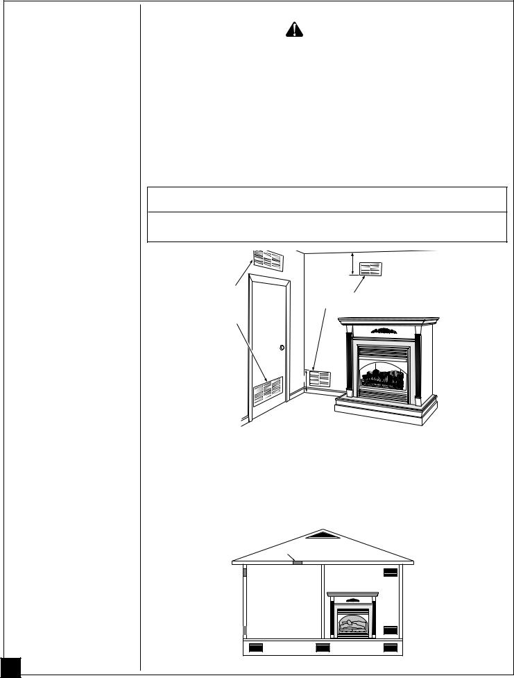
This fresh air would come from an adjoining unconfined space. When ventilating to an adjoining unconfined space, you must provide two permanent openings: one within 12" of the ceiling and one within 12" of the floor on the wall connecting the two spaces (see options 1 and 2, Figure 3). You can also remove door into adjoining room (see option 3, Figure 3). Follow the National Fuel Gas Code NFPA 54/ANSI Z223.1, Section 5.3, Air for Combustion and Ventilation for required size of ventilation grills or ducts.
 WARNING
Rework worksheet, adding the space of the adjoining unconfined space. The combined spaces must have enough fresh air to supply all appliances in both spaces.
|
|
12" |
|
Ventilation |
|
Ventilation Grills |
|
Grills |
|
||
Into Adjoining |
Or |
Into Adjoining Room, |
|
Room, |
Option 2 |
||
Remove |
|||
Option 1 |
|
||
Door into |
|
||
|
|
||
|
Adjoining |
|
|
|
Room, |
|
|
|
Option |
,,QQ¢¢ |
|
|
3 |
||
|
|
||
|
12" |
,,QQ¢¢ |
|
|
|
,,QQ¢¢,Q¢ |
Figure 3 - Ventilation Air from Inside Building
Ventilation Air From Outdoors
Provide extra fresh air by using ventilation grills or ducts. You must provide two permanent openings: one within 12" of the ceiling and one within 12" of the floor. Connect these items directly to the outdoors or spaces open to the outdoors. These spaces include attics and crawl spaces.
IMPORTANT: Do not provide openings for inlet or outlet air into attic if attic has a thermostatcontrolled power vent. Heated air entering the attic will activate the power vent.
|
Outlet |
Ventilated |
|
|
Attic |
|
|
|
Air |
|
|
|
|
|
|
Outlet |
|
|
|
Air |
|
|
To Attic |
|
|
|
|
|
|
¢¢¢¢QQQQ,,,, |
To |
|
|
¢¢¢¢QQQQ,,,, |
Crawl |
Inlet |
|
¢¢¢¢QQQQ,,,, |
Space |
|
¢¢¢¢QQQQ,,,, |
|
|
Air |
|
¢¢¢¢QQQQ,,,, |
|
|
Inlet Air |
Ventilated |
|
|
Crawl Space |
||
|
|
||
8 |
Figure 4 - Ventilation Air from Outdoors |
||
103415
INSTALLING |
|
NOTICE |
|
|
A qualified service person must install fireplace. Follow all local codes. |
|
|
|
|
|
|
|
|
WARNING |
|
|
Never install the fireplace |
|
|
• in a bedroom or bathroom |
|
|
• in a recreational vehicle |
|
|
• where curtains, furniture, clothing, or other flammable objects are less than |
|
|
36 inches from the front, top, or sides of the fireplace |
|
|
• in high traffic areas |
|
|
• in windy or drafty areas |
|
|
|
|
|
|
|
|
WARNING |
|
|
Models VSGF28PTB/CSGF28PTB have a three-prong, grounded electrical plug. |
|
|
This plug helps protect you against electrical shock. Only connect plug to a |
|
|
properly grounded, three-prong receptacle. Do not cut or remove the grounding |
|
|
prong from this plug. |
|
|
|
|
|
|
|
|
CAUTION |
|
|
This fireplace creates warm air currents. These currents move heat to wall sur- |
|
|
faces next to fireplace. Installing fireplace next to vinyl or cloth wall coverings or |
|
|
operating fireplace where impurities in the air (such as tobacco smoke) exist, may |
|
|
discolor walls. |
|
|
|
|
IMPORTANT: Vent-free heaters add moisture to the air. Although this is beneficial, installing |
|
|
fireplace in rooms without enough ventilation air may cause mildew to form from too much |
|
|
moisture. See Air for Combustion and Ventilation, pages 6 through 8. |
|
|
IMPORTANT: Make sure the fireplace is level. If fireplace is not level, log set will not work |
|
|
properly. |
|
|
CHECK GAS TYPE |
|
|
Use only propane gas. If your gas supply is not propane gas, do not install fireplace. Call dealer |
|
|
where you bought fireplace for proper type fireplace. |
|
|
ELECTRICAL HOOKUP (Models VSGF28PTB/CSGF28PTB ) |
|
|
This fireplace has a blower assembly with an electrical cord. The electrical cord is five feet in |
|
|
length. You must locate fireplace within reach of a 120 volt grounded electrical outlet. If not, |
|
|
you must install an electrical outlet within reach of fireplace power cord. |
|
|
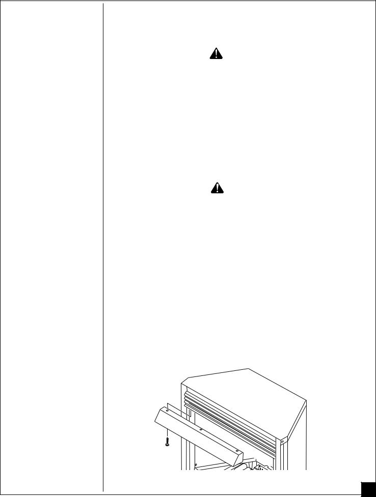
INSTALLING HOOD |
|
|
Install hood to top of fireboxas shown in Figure 5. Use 3 Phillips screws provided. |
|
Figure 5 - Installing Hood to Firebox
Continued
9
103415
INSTALLING
Continued
10
ASSEMBLING AND ATTACHING OPTIONAL BRASS TRIM (Included with Mantel Accessory)
IMPORTANT: If you are recessing the firebox in a wall, do not attach brass trim at this time. See page 13.
Note: The instructions below show assembling and attaching brass trim to fireplace.
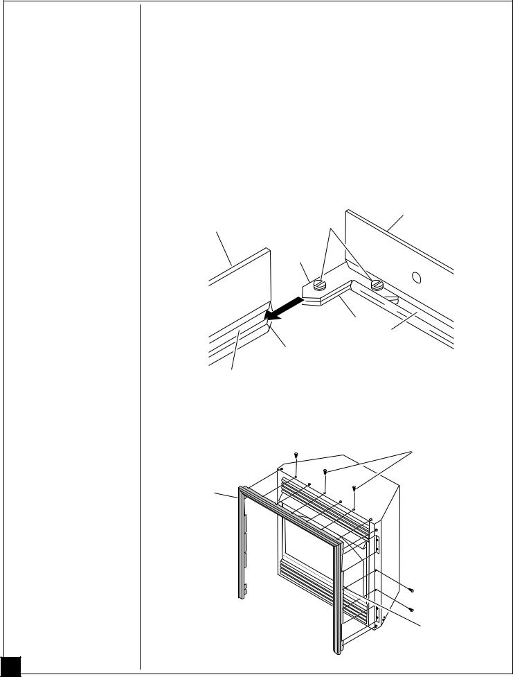
1.Remove packaging from three pieces of brass trim.
2.Locate four brass screws, two adjusting plates with set screws, and two shims in the hardware packet.
3.Align shim under adjusting plate as shown in Figure 6.
4.Slide one end of adjusting plate/shim in slot on mitered edge of top brass trim (see Figure 6).
5.Slide other end of adjusting plate/shim in slot on mitered edge of side brass trim (see Figure 6).
6.While firmly holding edges of brass trim together, tighten both set screws on the adjusting plate with slotted screwdriver.
7.Repeat steps 1 through 6 for other side.
Top Brass Trim
Side Brass Trim |
Set Screws |
|
Adjusting
Plate
Shim
Slot
Mitered Edge
Slot
Figure 6 - Assembling Brass Trim
8.Tighten trim hanging screws (#10 x 6.25 shoulder) into holes in cabinets. Place the assembled trim onto fireplace cabinet. Align hanging notches on trim with hanging screws on side of fireplace (see Figure 7). Push trim firmly into place, sliding hanging notches over hanging screws.
Trim Hanging
Screws
Assembled
Brass Trim
Hanging
Notches on Trim
Figure 7 - Attaching Brass Trim to Fireplace
103415
INSTALLING |
INSTALLATION CLEARANCES |
Continued |
WARNING |
Maintain the minimum clearances. If you can, provide greater clearances from floor, ceiling, and adjoining wall.
Carefully follow the instructions below. This will ensure safe installation.
Minimum Wall and Ceiling Clearances (see Figure 8)
A.Clearances from the side of the fireplace opening to any combustible wall should not be less than 16 inches for a cabinet mantel or 12 inches for a corner installation.
B.Clearances from the top of the fireplace opening to the ceiling should not be less than 42 inches.
|
|
MINIMUM CLEARANCE |
|
Note: Clearances |
42" |
Side Wall - 16 " Cabinet and |
|
are the same if |
Face Mantel |
||
|
|||
using optional |
|
Ceiling - 42" Corner Mantel |
|
cabinet mantel or |
|
Floor - 0" |
|
built-in installation. |
|
|
|
16" |
,,,QQQ¢¢¢ |
||
Face or |
,,,QQQ¢¢¢ |
||
Cabinet |
|||
Mantel |
,,,QQQ¢¢¢ |
||
12" |
,,,QQQ¢¢¢ |
||
Corner |
|
|
|
Mantel |
|
|
|
Figure 8 - Minimum Clearance to Wall and Ceiling |
|||
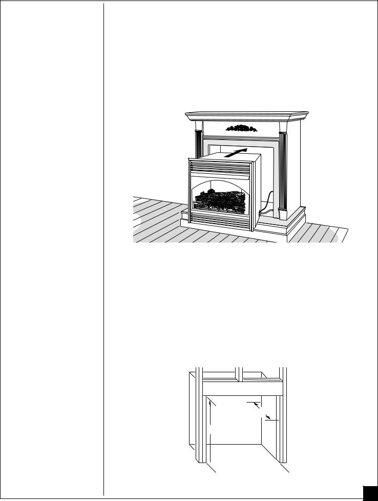
CONVENTIONAL FIREPLACE INSTALLATION
Conventional installation of this fireplace involves installing fireplace along with the corner, face, or cabinet mantel with hearth base accessories against a wall in your home. Follow the instructions below to install the fireplace in this manner.
WARNING
WARNING ICON |
G 001 |
For conventional installation, it is recommended you use the cabinet mantel, corner mantel, face mantel, or hearth bases specified in this manual. Surface clearances may not be sufficient with other cabinet mantels and hearth bases. This may create a fire hazard. See Accessories, pages 34 and 35 for correct mantels and hearth bases.
Note: The instructions below show installation using the cabinet mantel and the G3000F/G3001U series hearth base accessories. The hearth base accessory shown is optional for this installation. You can install fireplace and cabinet mantel directly on the floor. The corner mantel and face mantel accessories cannot be installed with the G3000F/G3001U hearth base. You must install corner and face mantel directly on the floor. If mounting fireplace and cabinet mantel to the floor or using face mantel or corner mantel, an optional G3005 Slim Base kit may be installed.
1.Assemble cabinet mantel, hearth base, and trim accessories. Assembly instructions are included with each accessory.
2.When installing blower, install a properly grounded, 120 volt three-prong electrical outlet at fireplace location if an outlet is not there. If possible, locate outlet so cabinet mantel will cover it when installed (see Figure 9, page 12).
Continued
11
103415
INSTALLING
Continued
12
3.Install gas piping to fireplace location. This installation includes an approved flexible gas line (if allowed by local codes) after the manual shutoff valve. The flexible gas line must be the last item installed on the gas piping. See Installing Gas Piping to Fireplace Location, page 15.
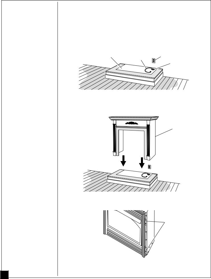
4.Place hearth base accessory against wall at installation location. Cut an access hole in hearth top to run flexible gas line to fireplace (see Figure 9). Make sure to locate access hole so cabinet mantel will cover it when installed. Note: You can secure base to floor using wood screws. Countersink screw heads and putty over.
Hearth Base |
Flexible Gas Line |
Electrical Outlet |
|
|
Gas Line Access
,,,,,QQQQQ¢¢¢¢¢ Hole
,,,,,QQQQQ¢¢¢¢¢
Figure 9 - Placing Hearth Base Accessory Against Wall
5.Route flexible gas line through access hole in hearth base.
6.Center cabinet mantel on hearth base (see Figure 10). Make sure mantel is flush against wall.
,,,QQQ¢¢¢
Cabinet Mantel
,,,QQQ¢¢¢
,,,QQQ¢¢¢
,,,QQQ¢¢¢
,,,,,QQQQQ¢¢¢¢¢
,,,,,QQQQQ¢¢¢¢¢
Figure 10 - Installing Cabinet Mantel
7. Break off nailing flanges (see Figure 11) with hammer or pliers.
 Nailing Flanges
Figure 11 - Location of Nailing Flanges
8.Place cardboard or other protective material on top of hearth base. Carefully set fireplace on protective material, with back of fireplace inside mantel opening.
103415
INSTALLING |
9. Attach flexible gas line to fireplace gas regulator. See Connecting Fireplace to Gas Supply, |
|
page 17. |
||
|
Continued 10. If blower is installed, route blower electrical cord through access holes in either side of fireplace. Note: Bushing may be moved if necessary. Plug electrical cord into electrical outlet.
11.Carefully insert fireplace into cabinet mantel. Be careful not to scratch or damage hearth base, cabinet mantel, or any laminate trim on hearth base. Remove protective material from top of hearth base and from front of fireplace (if any). Note: You can secure fireplace to hearth or floor. Open lower louver. Locate screw holes in bottom of base. Tighten wood screws through these holes and into hearth or floor.
12.Check all gas connections for leaks. See Checking Gas Connections, page 18.
,,,QQQ¢¢¢ |
,,,QQQ¢¢¢ |
,,,QQQ¢¢¢ |
,Q¢,,,QQQ¢¢¢,Q¢ |
,,,,,QQQQQ¢¢¢¢¢ |
Figure 12 - Inserting Fireplace Into Cabinet Mantel
BUILT-IN FIREPLACE INSTALLATION
Built-in installation of this fireplace involves installing fireplace into a framed-in enclosure. This makes the front of fireplace flush with wall. If installing a mantel above the fireplace, but you must follow the clearances shown in Figure 16, page 15. Follow the instructions below to install the fireplace in this manner.
Height |
Front Width |
Depth |
|||
|
|
|
|
|
|
Actual |
Framing |
Actual |
Framing |
Actual |
Framing |
|
|
|
|
|
|
32 3/8" |
33" |
34 5/16" |
35 1/2" |
16 11/16" |
17 3/4" |
1. Frame in rough opening. Use dimensions shown in Figure 13 for the rough opening.
17 3/4"
33"

 35 1/2"
Figure 13 - Rough Opening for Installing in Wall
Continued 13
103415
INSTALLING
Continued
14
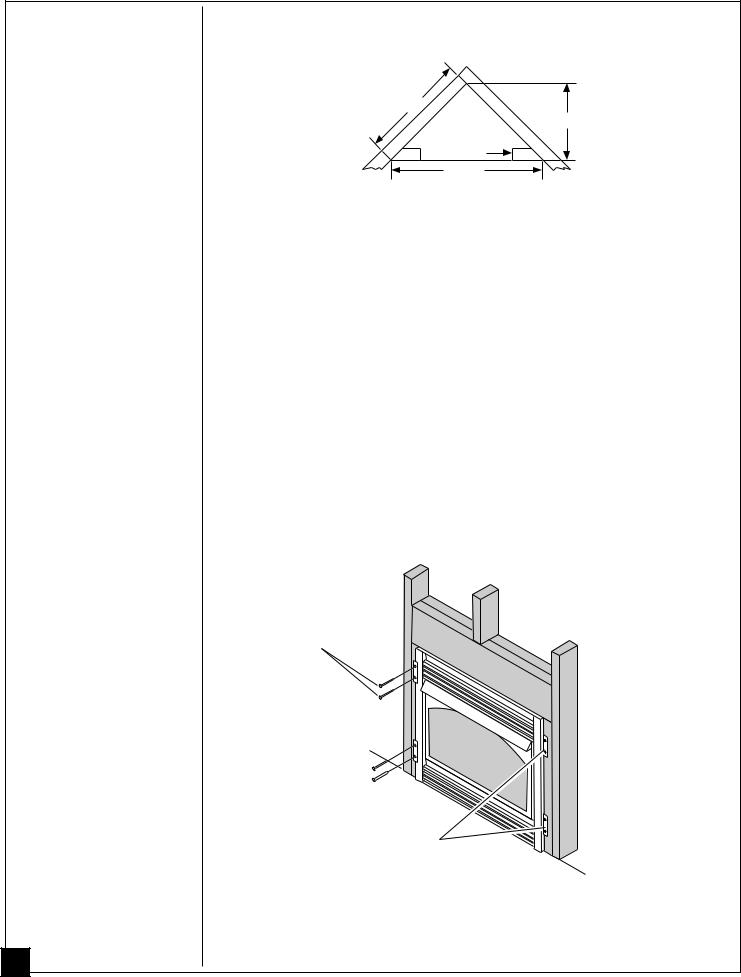
If installing in a corner, use dimensions shown in Figure 14 for the rough opening. The height is 33" which is the same as the wall opening above.
39 3/8"
27 7/8"
 35 1/2" 55 5/8"
Figure 14 - Rough Opening for Installing in Corner
2.If using blower, install and properly ground GA3555, three-prong 120 volt electrical outlet, in fireplace. Follow instructions included in kit.
3.Install gas piping to fireplace location. This installation includes an approved flexible gas line (if allowed by local codes) after the manual shutoff valve. The flexible gas line must be the last item installed on the gas piping. See Installing Gas Piping to Fireplace Location, page 16.
4.Carefully set fireplace in front of rough opening with back of fireplace inside wall opening.
5.Attach flexible gas line to gas supply. See Connecting Fireplace to Gas Supply, page 17.
6.Plug electrical cord into electrical outlet installed in step 2.
7.Carefully insert fireplace into rough opening.
8.Attach fireplace to wall studs using nails or wood screws through holes in nailing flange (see Figure 15).
9.Check all gas connections for leaks. See Checking Gas Connections, page 18.
10.Install brass trim after final finishing and/or painting of wall (see Figure 7, page 10).
Nails or Wood
Screws
Nailing Flanges
Figure 15 - Attaching Fireplace to Wall Studs
103415
 Loading...