

Page 1

GAS LOG VENTED
DECORATIVE AP PLI ANCE
OWNER’S OPERATION AND
INSTALLATION MAN U AL
For more information, visit www.desatech.com
VTD-24N-PDG, VTD-24P-PDG,
VTD-18N-PDG, VTD-18P-PDG
ANSI Z21.60-2003
CSA 2.26-2003
APPROVED
WARNING: If the information in this man u al
is not followed exactly, a fi re or explosion
may result caus ing prop er ty damage, per son al in ju ry, or loss of life.
— Do not store or use gasoline or other
fl ammable vapors and liq uids in the vicinity
of this or any other ap pli ance.
— WHAT TO DO IF YOU SMELL GAS
• Do not try to light any appliance.
• Do not touch any electrical switch; do not
use any phone in your build ing.
• Immediately call your gas sup pli er from
a neigh bor’s phone. Follow the gas sup pli er’s in struc tions.
• If you cannot reach y our gas sup plier , call
the fi re de part ment.
— Installation and service must be per formed
by a qualifi ed installer, ser vice agen cy, or
the gas supplier.
VTD-24N-BTB, VTD-24P-BTB,
VTD-18N-BTB, VTD-18P-BTB
WARNING: Improper in stal la tion, ad just ment, al tera tion, service, or main te nance can cause injury or prop er ty
dam age. Re fer to this man u al for
cor rect in stal la tion and op er a tion al
pro ce dures. For as sis tance or ad di tional in for ma tion con sult a qualifi ed
in stall er, ser vice agen cy, or the gas
sup plier.
WARNING: This appliance is for in stal la tion only in a solid-fuel burn ing ma son ry or UL127 fac to ry-built
fi re place, con struct ed of non com bus ti ble ma te ri al, and con nect ed
to a working fl ue. (See page 7 for
min i mum fl ue open ing.)
WARNING: This is a gas-fi red ap pli ance. It uses air (ox y gen) from the room in which it is installed.
Pro vi sions for ad e quate com bus tion and ven ti la tion air must be provided. Refer to the National
Fuel Gas Codes, ANSI Z233.1/NFPA 54, Section 5.3, Air for Combustion and Ventilation.
This appliance may be installed in an aftermarket,* manufactured (mobile) home, where not
pro hib it ed by local codes.
This appliance is only for use with the type of gas indicated on the rating plate. This ap pli ance
is not convertible for use with other gases.
Warning: This product must be installed by a Licensed Plumber or Gas Fitter when installed
within The Commonwealth of Massachusetts.
* Aftermarket: Completion of sale, not for purpose of resale, from the manufacturer
Save this manual for future reference.
Page 2
TABLE OF CONTENTS
2
SAFETY INFORMATION
TABLE OF CONTENTS
SAFETY INFORMATION..............................................................2
LOCAL CODES............................................................................3
PRODUCT IDENTIFICATION.......................................................3
UNPACKING.................................................................................4
PRODUCT FEATURE ..................................................................4
INSTALLATION ............................................................................7
OPERATING AP PLI ANCE..........................................................11
INSPECTING BURNERS ..........................................................13
SAFETY INFORMATION
WARNING ICON G 001
WARNINGS
WARNING: Keep fl ue open when operating unit.
IMPORTANT: Read this owner’s man u al carefully and
completely be fore trying to assemble, op er ate, or ser vice this log set. Im prop er use of this log set can cause
se ri ous injury or death from burns, fi re, ex plo sion, electrical shock, and carbon mon ox ide poi son ing.
DANGER: Carbon mon ox ide poisoning may lead
to death!
WARNING: This product contains and/or generates
chemicals known to the State of California to cause
cancer or birth defects, or other reproductive harm.
Carbon Monoxide Poisoning: Early signs of carbon mon ox ide
poisoning re sem ble the fl u, with head aches, dizziness, or nau sea.
If you have these signs, the log set may not be working properly.
Get fresh air at once! Have log set serviced. Some people are more
affected by carbon monoxide than others. These include preg nant
wom en, peo ple with heart or lung disease or ane mia, those under
the in fl u ence of alcohol, and those at high altitudes.
Natural & LP Gas : Natural & LP gas are odorless. An odor-mak-
ing agent is added to the gas. The odor helps you detect a gas leak.
However, the odor added to the gas can fade. Gas may be present
even though no odor exists.
Make certain you read and understand all warnings. Keep this
manual for reference. It is your guide to safe and proper operation
of this log set.
W ARNING: Any change to this log set or its controls can be dan ger ous.
1. This appliance, as supplied, is only for use with the type of gas
indicated on the rating plate.
2. If you smell gas
• shut off gas supply
CLEANING AND MAINTENANCE .............................................13
TROUBLESHOOTING................................................................14
REPLACEMENT PARTS ............................................................18
ILLUSTRATED PARTS BREAKDOWN AND PARTS LIST.........20
ACCESSORIES..........................................................................22
OWNER'S REGISTRATION FORM............................................23
WARRANTY INFORMATION ...................................... Back Cover
• do not try to light any appliance
• do not touch any elec tri cal switch; do not use any phone in
your build ing
• immediately call your gas supplier from a neighbor’s phone.
Follow the gas supplier’s instructions
• if you cannot reach your gas sup plier, call the fi re de part ment
3. Never install the log set
• in a recreational vehicle
• where curtains, furniture, clothing, or other fl ammable ob jects are less than 42 inches from the front, top, or sides of
the log set
• in high traffi c areas
• in windy or drafty areas
4. Before installing in a solid fuel burn ing fi replace, the chim ney
fl ue and fi re box must be cleaned of soot, creosote, ash es and
loose paint by a qualifi ed chimney cleaner . Creosote will ig nite
if highly heated. Inspect chimney fl ue for damage. If dam aged,
repair fl ue before operating appliance.
5. Y ou must operate this log set with fi replace doors or screens in
place and fully closed. Unless provided by other means, screens
shall have openings for in tro duc tion of combustion air.
6. This log set is designed to be smoke less. If logs ever appear to
smoke, turn off appliance and call a qual i fi ed ser vice per son.
Note: During ini tial op er a tion, slight smok ing could oc cur due
to log curing and the burning of man u fac tur ing res i dues. You
may wish to add more ventilation by opening a win dow.
7. T o reduce the creation of soot, follow the in struc tions in Clean-
ing and Main te nance, page 13.
8. Do not allow f ans to blow directly into the fi replace. Avoid any
drafts that al ter burner fl ame patterns. Ceiling fans can create
drafts that alter burner fl ame patterns. Altered burner patterns
can increase sooting.
9. Do not use a blower insert, heat ex chang er insert or other ac ces so ry not approved for use with this log set.
10. The installation and provisions for combustion and ventilation air
must conform with the National Fuel Gas Codes, ANSI Z233.1/
NFPA 54, Section 5.3, Air for Combustion and Ven ti la tion.
11. Do not run log set
• where fl ammable liquids or vapors are used or stored
• under dusty conditions
For more information, visit www.desatech.com
111826-02F
Page 3
SAFETY INFORMATION
Continued
12. Do not burn solid fuel in the fi replace after installing the log
set. Do not use this log set to cook food or burn pa per or oth er
ob jects.
13. Log set becomes very hot when in use. Keep chil dren and adults
away from hot sur face to avoid burns or clothing ig ni tion. Log
set will re main hot for a time after shutdown. Al low surface to
cool be fore touch ing.
14. Carefully supervise young children when they are in the room
with log set.
15. Do not use this appliance if any part has been under water.
Immediately call a qualifi ed service technician to inspect the
appliance and to replace any part of the control system and any
gas control which has been under water.
17. Turn log set of f and let cool before ser vic ing, installing, or re pair ing. Only a qualifi ed service person should install, ser vice,
or repair log set.
18. Keep the appliance area clear and free from combustible ma te ri als, gasoline and other fl ammable vapors and liquids.
19. Provide adequate clearances around air openings.
W ARNING: Do not place log scraps or la v a roc ks
on burner.
SAFETY INFORMATION
LOCAL CODES
PRODUCT IDENTIFICATION
3
3
LOCAL CODES
Install and use appliance with care. Follow all local codes. In the
absence of local codes, use the latest edition of The National Fuel
Gas Code ANSI Z223.1/NFPA 54*.
*Available from:
American National Standards In sti tute, Inc.
1430 Broadway
New York, NY 10018
National Fire Protection Association, Inc.
Batterymarch Park
Quincy, MA 02269
PRODUCT IDENTIFICATION
Log Set
WARNING: Any change to this log set or its controls
can be dangerous.
WARNING: Do not use a blow er insert, heat ex chang er insert, or other accessory not ap proved for
use with this appliance.
WARNING: Keep fl ue open when operating unit.
Appliance base assembly be comes very hot when
run ning appliance. Keep chil dren and adults away
from hot surface to avoid burns or clothing ignition.
Appliance will remain hot for a time after shut down.
Allow surface to cool be fore touching.
Carefully supervise young chil dren when they are in
the room with appliance. When using the hand-held
remote accessory (Remote-Ready Models Only), keep
se lec tor switch in the OFF position to prevent chil dren
from turn ing on burners with remote.
Y ou must operate this appliance with a fi re place screen
in place. Make sure fi re place screen is closed before
run ning appliance.
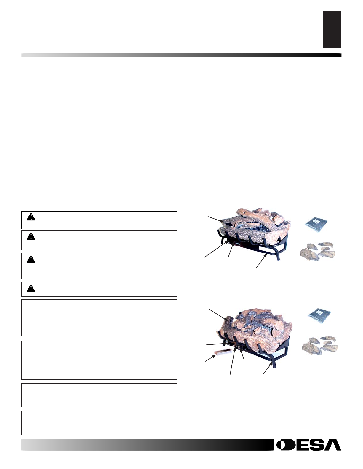
Piezo
Ignitor
Log Set
Piezo
Ignitor
Remote
Control
Control Knobs
Control Knobs
REMOTE CONTROLLED MODELS
Chassis Assembly
REMOTE READY MODELS
Remote
Reciever
Chassis Assembly
Lava Rock
Log Scraps
Lava Rock
Log Scraps
Keep the appliance area clear and free from com bus ti ble materials, gasoline, and other fl ammable
vapors and liquids.
For more information, visit www.desatech.com
111826-02F
Figure 1 - Product Identifi cation
Page 4

OPTIONAL REMOTE CONTROL ACCESSORIES
4
UNPACKING
PRODUCT FEATURES
AIR FOR COMBUSTION AND VENTILATION
Providing Adequate V entilation
OPTIONAL REMOTE CONTROL
ACCESSORIES
There are two optional remote controls that can be purchased separately for Remote-Ready Models:
• wall switch • hand-held ON/OFF remote
See Accessories, page 22.
The wall thermostat or hand-held ther mo stat may not be used with
vented dec o ra tive appliances.
UNPACKING
CA UTION: Do not remove the data plates from the
grate assembly. The data plates con tain im por tant
warranty and safety in for ma tion.
1. Remove log set as sem bly from carton. Note: Do not pick up
assembly by logs. This could dam age the unit. Alw ays handle
assembly by grate.
2. Remove control cover fl oor media components & remote
control if supplied.
3. Remove all protective packaging ap plied to log set for shipment.
4. Check all items for any shipping dam age. If damaged, prompt ly
inform deal er where you bought appliance.
PRODUCT FEATURES
REMOTE READY & REMOTE CONTROLLED
This unitized gas log set is tested and approved to ANSI Z21.60a
and CSA 2.26a-2000 as a vented decorati ve appliance. This log set
has a piezo ignitor . This system requires no matches, batteries or
other source to light log set.
SAFETY DEVICE
This unit has a pilot with an Oxygen Depletion Sensing (ODS)
safety shutoff sys tem. The ODS/pilot shuts off the appliance if there
is not enough fresh air.
PIEZO IGNITION SYSTEM
This unit has a piezo ignitor. This system requires no matches, batteries, or other sourc es to light appliance.
AIR FOR COMBUSTION AND
VENTILATION
W ARNING: This appliance shall not be installed in
a confi ned space or unusually tight con struc tion un less pro vi sions are pro vid ed for ad e quate com bus tion
and ven ti la tion air. Read the fol low ing in struc tions to
in sure prop er fresh air for this and other fuel-burning
ap pli anc es in your home.
Today’s homes are built more energy ef fi cient than ever. New ma te ri als,
increased in su la tion, and new construction methods help reduce heat
loss in homes. Home own ers weather strip and caulk around windows
and doors to keep the cold air out and the warm air in. During heating
months, home owners want their homes as airtight as pos si ble.
While it is good to make your home energy effi cient, your home
needs to breathe. Fresh air must enter your home. All fuel-b urning
appliances need fresh air for proper com bus tion and ven ti la tion.
Exhaust fans, fi replaces, clothes dryers, and fuel burning appliances
draw air from the house to operate. Y ou must provide ad e quate fresh
air for these ap pli anc es. This will insure proper venting of vented
fuel-burning appliances.
PROVIDING ADEQUATE VENTILATION
The following are excerpts from National Fuel Gas Code, ANSI
Z223.1/NFPA 54, Sec tion 5.3, Air for Combustion and Ven ti la tion.
All spaces in homes fall into one of the three following ventilation
classifi cations:
1. Unusually Tight Construction
2. Unconfi ned Space
3. Confi ned Space
The information on pages 4 through 6 will help you classify your
space and provide ad e quate ven ti la tion.
Unusually Tight Construction
The air that leaks around doors and win dows may provide enough
fresh air for combustion and ventilation. Howe ver, in buildings of unusually tight construction, you must provide additional fresh air.
Unusually tight construction is de fi ned as construction
where:
a. walls and ceilings exposed to the outside at mo sphere
have a con tin u ous water vapor retarder with a rating
of one perm (6 x 10
open ings gasketed or sealed and
b. weather stripping has been add ed on openable win-
dows and doors and
c. caulking or sealants are applied to areas such as
joints around window and door frames, be tween sole
plates and fl oors, be tween wall-ceiling joints, be tween
wall panels, at pen e tra tions for plumb ing, electrical,
and gas lines, and at other openings.
If your home meets all of the three criteria above, you
must pro vide ad di tion al fresh air . See Ventilation Air
From Outdoors, page 5.
If your home does not meet all of the three criteria above,
proceed to De ter min ing Fresh-Air Flow For Appliance
Lo ca tion, below.
-11
kg per pa-sec-m2) or less with
For more information, visit www.desatech.com
111826-02F
Page 5

AIR FOR COMBUSTION AND VENTILATION
Providing Adequate V entilation (Cont.)
Determining Fresh-Air Flow for Appliance Location
V entilation Air
5
5
AIR FOR COMBUSTION AND
VENTILATION
Continued
Confi ned and Unconfi ned Space
The National Fuel Gas Code, ANSI Z223.1/NFPA 54 defi nes a
con fi ned space as a space whose volume is less than 50 cubic feet
per 1,000 Btu per hour (4.8 m3 per kw) of the ag gre gate input rating
of all ap pli anc es in stalled in that space and an un con fi ned space as
a space whose vol ume is not less than 50 cubic feet per 1,000 Btu
per hour (4.8 m3 per kw) of the ag gre gate input rating of all appliances in stalled in that space. Rooms com mu ni cat ing di rect ly with
the space in which the ap pli anc es are in stalled*, through openings
not fur nished with doors, are con sid ered a part of the unconfi ned
space.
* Adjoining rooms are communicating only if there are doorless
passageways or ven ti la tion grills between them.
DETERMINING FRESH-AIR FLOW FOR
APPLIANCE LOCATION
Determining if You Have a Confi ned or Unconfi ned
Space
Use this work sheet to determine if you have a confi ned or un con fi ned
space.
Space: Includes the room in which you will install appliance plus any
adjoining rooms with doorless passageways or ventilation grills between
the rooms.
1. Determine the volume of the space (length x width x height).
Length x Width x Height =____________cu. ft. (vol ume of space)
Example: Space size 20 ft. (length) x 16 ft. (width) x 8 ft. (ceil ing
height) = 2560 cu. ft. (vol ume of space)
If additional ventilation to adjoining room is supplied with grills or open-
ings, add the volume of these rooms to the total vol ume of the space.
2. Multiply the space volume by 20 to determine the maximum Btu/Hr
the space can support.
____________(volume of space) x 20 = (Maximum Btu/Hr the space
can sup port)
Example: 2560 cu. ft. (volume of space) x 20 = 51,200 (max i mum
Btu/Hr the space can sup port)
3. Add the Btu/Hr of all fuel burning ap pli anc es in the space.
Vent-free appliance _____________ Btu/Hr
Gas wa ter appliance* _____________ Btu/Hr
Gas fur nace _____________ Btu/Hr
Vented gas appliance _____________ Btu/Hr
Gas fi re place logs _____________ Btu/Hr
Other gas appliances* + _____________ Btu/Hr
Total = _____________ Btu/Hr
* Do not include direct-vent gas ap pli anc es. Direct-vent draws com-
bus tion air from the outdoors and vents to the outdoors.
Example:
Gas water appliance _____________ Btu/Hr
Vent-free appliance + _____________ Btu/Hr
Total = _____________ Btu/Hr
4. Compare the maximum Btu/Hr the space can support with the actual
amount of Btu/Hr used.
____________________Btu/Hr (maximum the space can sup port)
____________________Btu/Hr (actual amount of Btu/Hr used)
Example: 51,200 Btu/Hr (max i mum the space can support)
73,000 Btu/Hr (actual amount of Btu/Hr used)
The space in the above example is a con fi ned space because the actual
Btu/Hr used is more than the maximum Btu/Hr the space can sup port. Y ou
must provide additional fresh air. Your op tions are as follows:
A. Rework worksheet, adding the space of an adjoining room. If the ex tra
space provides an unconfi ned space, remove door to ad join ing room or
add ven ti la tion grills between rooms. See Ven ti la tion Air From Inside
Building, page 6.
B. V ent room directly to the outdoors. See V entilation Air F rom Out doors,
page 6.
C. Install a lower Btu/Hr appliance, if lower Btu/Hr size makes room un con -
fi ned.
If the actual Btu/Hr used is less than the maximum Btu/Hr the space can sup port, the space is an unconfi ned space. You will need no additional fresh air
ven ti la tion.
40,000
33,000
73,000
WARNING: If the area in which the appliance
may be operated is smaller than that defi ned as an
un con fi ned space or if the building is of unusually
tight construction, pro vide ad e quate com bus tion and
ven ti la tion air by one of the methods described in
the National Fuel Gas Code, ANSI Z223.1/NFPA 54
Sec tion 5.3 or applicable local codes.
VENTILATION AIR
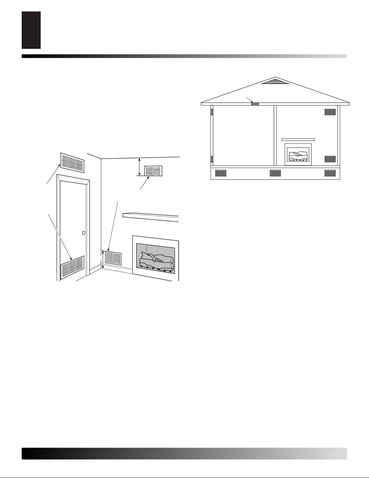
Ventilation Air From Inside Building
This fresh air would come from an adjoining unconfi ned space. When
ventilating to an adjoining unconfi ned space, you must pro vide two
permanent open ings: one within 12" of the ceiling and one within
12" of the fl oor on the wall con nect ing the two spaces (see options
1 and 2, Figure 2). You can also remove door into adjoining room
(see op tion 3, Figure 2). Follow the National Fuel Gas Code, ANSI
Z223.1/NFPA 54, Section 5.3, Air for Combustion and Ventilation
for required size of ventilation grills or ducts.
Ventilation Air From Outdoors
Provide extra fresh air by using ventilation grills or ducts. You
must provide two per ma nent open ings: one within 12" of the ceiling and one within 12" of the fl oor. Connect these items directly to
111826-02F
For more information, visit www.desatech.com
Page 6
I
AIR FOR COMBUSTION AND VENTILATION
6
V entilation Air (Cont.)
AIR FOR COMBUSTION AND
VENTILATION
Continued
the outdoors or spaces open to the outdoors. These spaces include
attics and crawl spaces. Follow the National Fuel Gas Code, ANSI
Z223.1/NFPA 54, Section 5.3, Air for Combustion and Ventilation
for required size of ven ti la tion grills or ducts.
IMPORTANT: Do not provide openings for inlet or outlet air into
attic if attic has a ther mo stat-controlled power vent. Heated air
entering the attic will activate the power vent.
12"
Ventilation
Grills
nto Adjoining
Room,
Option 1
Or
Remove
Door into
Adjoining
Room,
Option
3
Ventilation Grills
Into Adjoining Room,
Option 2
Outlet
Air
Outlet
Air
Inlet
Air
Inlet Air
Figure 3 - Ventilation Air from Outdoors
Ventilated
Attic
To Attic
To
Crawl
Space
Ventilated
Crawl Space
12"
Figure 2 - Ventilation Air from Inside Building
For more information, visit www.desatech.com
111826-02F
Page 7
INSTALLATION
Flue Opening Specifi cations
Installation and Clearances
Venting Specifi cations for Installation
Installing Damper Clamp
7
7
INSTALLATION
WARNING: Before installing in a solid fuel burn ing fi replace, the chimney fl ue and fi rebox must be
cleaned of soot, creosote, ash es and loose paint by
a qual i fi ed chim ney cleaner. Creosote will ignite if
highly heated. A dirty chimney fl ue may create and
dis trib ute soot within the house. In spect chim ney fl ue
for damage. If damaged, repair fl ue damper before
operating appliance.
W ARNING: Make sure the selector switch is in the
OFF po si tion before installing appliance .
WARNING: Before installing in a solid fuel burn ing fi replace, the chimney fl ue and fi rebox must be
cleaned of soot, creosote, ash es and loose paint by
a qual i fi ed chim ney cleaner. Creosote will ignite if
highly heated. A dirty chimney fl ue may create and
dis trib ute soot within the house. In spect chim ney
fl ue for damage.
NOTICE: Installation, service, and repair of this ap pli ance must be performed by a qualifi ed in stall er,
ser vice agency, com pa ny or gas supplier ex pe ri enced
with this type of gas ap pli ance. Only fac to ry au tho rized
components list ed in these in struc tions may be used
in ac cor dance with the man u fac tur er’s in struc tions
and all codes and requirements of the authority having ju ris dic tion. Any modifi cations to this kit, or use
of unauthorized com po nents or ac ces so ry items will
void the man u fac tur er’s war ran ty, and may result in
a haz ard ous condition.
FLUE OPENING SPECIFICATIONS
Note: This vented appliance must be in stalled only in a solid-fuel
burning fi replace with a working fl ue and constructed of non com bus ti ble material.
The charts in Figure 4 indicate technical in for ma tion regarding the
installation of your gas log set. Please make sure that all of the spec i fi ca tions shown are applicable be fore in stal la tion is at tempt ed.
The fi replace must include a working fl ue and venting system with
the minimum open ings shown in the Figure 5.
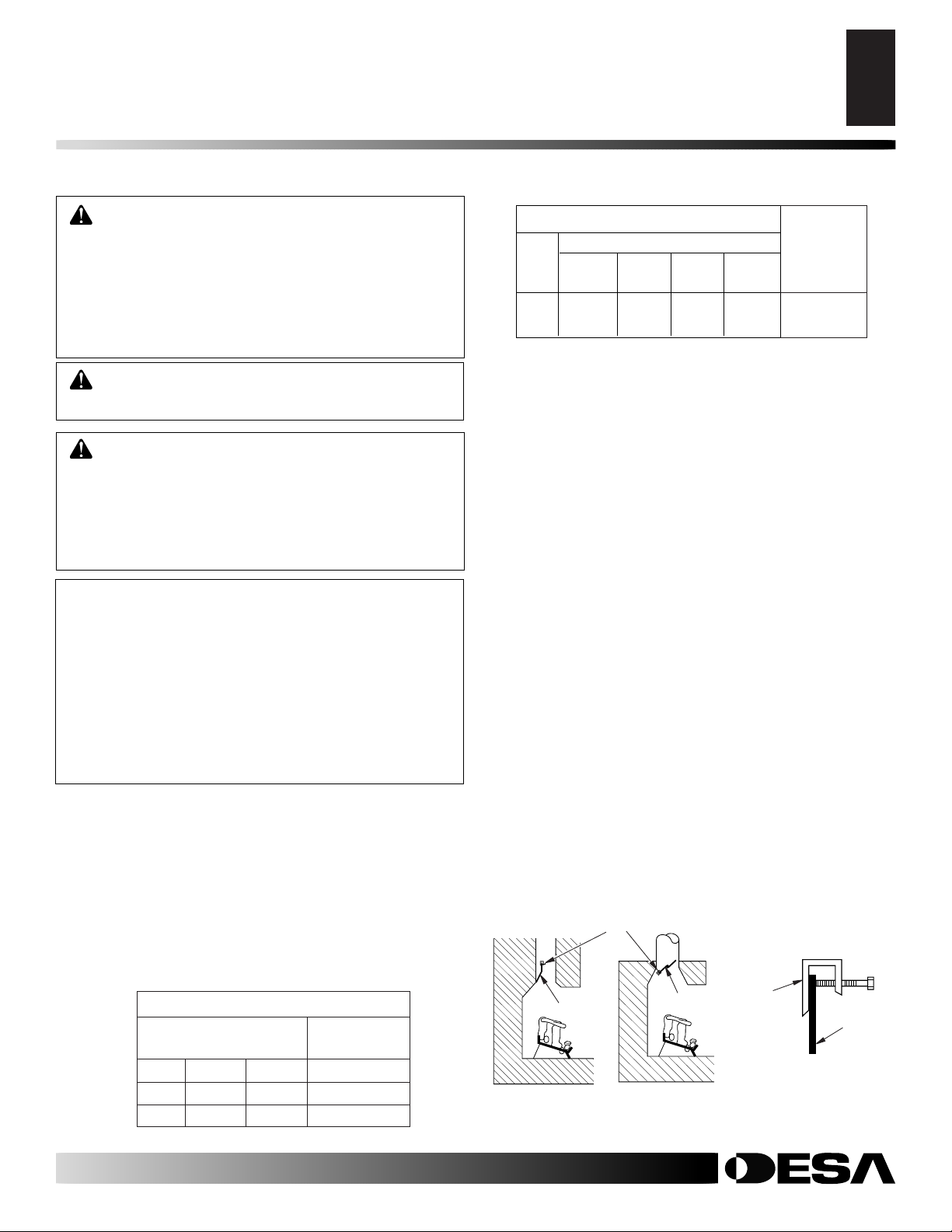
SPECIFICATIONS (W.C.)
FUEL INLET MANIFOLD
PRESSURE PRESSURE
Min. Max.
NG 7 10.5 3.5
LP 11 14 10
Figure 4 - Technical Information Charts
INSTALLATION AND CLEARANCES
LOG SIZING REQUIREMENTS Min.
Minimum Firebox Size Flue size
Log Front Rear*
Size Height Depth Width Width
18" 17" 14" 24" 20" 8"
24" 17" 14" 28" 22" 8"
*Measured at 14" depth
Figure 5 - Sizes & Clearances
CHECK GAS TYPE
Use the correct gas type (natural or propane/LP) for your unit. If
your gas supply is not correct, do not instal in fi replace. Call dealer
where you bought the appliance for proper type of appliance.
VENTING SPECIFICATIONS FOR
INSTALLATION
The fi replace chimney fl ue and vent must be draft ing properly. To
check the vent for proper drafting: Light a tightly rolled news pa per
on one end and place it at the inside front edge of the fi replace. Observe the smoke and be sure the vent is properly drawing it up the
chimney . If the smoke spills out into the room, extinguish the fl ame
and remove any obstruction until proper venting is achieved.
The chimney fl ue damper must be fi xed open to provide a min i mum
of 43 sq. in. of free air opening during operation of this log set. A multipurpose damper clamp is provided to fi x the damper in position.
The minimum fl ue sizes shown in Figure 5 are based on a 6' chimney
height using round pipe. Your minimum fl ue size will vary based
on input rate and chimney height. Refer to the National Fuel Gas
Code ANSI Z223.1/NFPA 54, Section 6.6, for details.
INSTALLING DAMPER CLAMP
Secure the damper stop clamp provided to the leading edge of the
damper as shown in Figure 6. If for any reason this clamp doesn't
work on your fi replace, an oth er suitable clamp or permanent stop
must be installed, or the damper blade must be cut or removed.
Damper Clamp
Damp er
Masonry Fireplace
Figure 6 - Attaching Damper Clamp
Manufactured
Fireplace
Damper
Damper
Clamp
Damper
111826-02F
For more information, visit www.desatech.com
Page 8
INSTALLATION
8
Installing Appliance Assembly
Connecting To Gas Supply
INSTALLATION
Continued
INSTALLING APPLIANCE ASSEMBLY
W ARNING: If installing in a sunken fi re place, special care is needed. Y ou must raise the fi re place fl oor
to allow access to appliance control panel. This will
in sure ad e quate air fl ow and guard against soot ing.
Raise fi replace fl oor with noncom bus ti ble ma te ri al.
Make sure material is secure.
CAUTION: Do not pick up appliance as sem bly by
logs. This could damage unit. Only handle assembly
by grates.
IMPORTANT: Make sure the appliance is level. If unit is not lev el,
unit will not work properly.
Installation Items Needed
• control cover kit (provided with appliance)
• approved fl exible gas hose and fi ttings (pro vid ed with appliance)
(if al lowed by lo cal codes)
• sealant (resistant to propane/LP gas, not pro vid ed)
Note: Install optional Hand-Held Remote Control Kit (see Ac ces -
so ries, page 22) before in stall ing gas log appliance (Remote-Ready
Models Only). See installation in struc tions in clud ed with the kit.
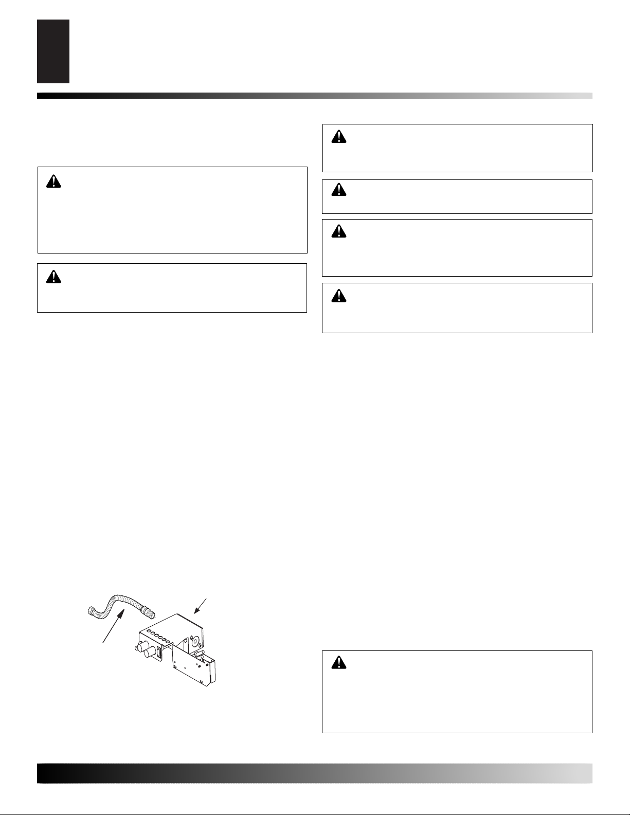
1. Apply pipe joint sealant lightly to male threads of gas fi tting
(not provided). Connect ap proved fl exible gas hose to inlet side
of gas con trol (see Figure 7).
2. Position appliance in fi re place.
3. Connect to gas supply. See Con nect ing To Gas Supply.
Gas Control
Flexible Gas
Hose (if allowed
by local codes)
CONNECTING TO GAS SUPPLY
WARNING: This appliance requires a 3/8" NPT
(National Pipe Thread) inlet connection to the pres sure regulator.
WARNING: A qualifi ed ser vice per son must con nect
appliance to gas sup ply. Follow all local codes.
CAUTION: Never connect propane/LP fi replace
directly to the propane/LP supply. This unit re quires
an external regulator (not supplied). Install the external
regu la tor be tween the unit and propane/LP supply.
W ARNING: Never connect natural gas fi replace to
pri vate (non-utility) gas wells. This gas is com mon ly
known as wellhead gas.
Installation Items Needed
Before installing appliance, make sure you have the items listed
below.
• external regulator (supplied by installer)
• piping (check local codes)
• sealant (resistant to propane/LP gas)
• equipment shutoff valve *
• test gauge connection *
• sediment trap
• tee joint
• pipe wrench
• approved fl exible gas line with gas con nec tor (if allo wed by lo cal
codes) (provided)
* A CSA design-certifi ed equipment shutoff valve with 1/8" NPT
tap is an ac cept able alternative to test gauge con nec tion. Pur chase
the optional CSA design-certifi ed equipment shutoff valve from
your dealer. See Accessories, page 22.
For propane/LP units, the installer must supply an external reg u la tor. The external re g u la tor will reduce incoming gas pressure. You
must reduce in com ing gas pressure to between 11 and 14 inches of
water. If you do not reduce in com ing gas pressure, regulator damage could occur. Install external reg u la tor with the vent point ing
down as shown in Figure 8 page 9. Pointing the vent do wn protects
it from freezing rain or sleet.
CA UTION: Use onl y new, blac k iron or steel pipe.
In ter nal ly-tinned copper tubing may be used in cer tain areas. Check your local codes. Use pipe of 1/2"
di am e ter or greater to allow prop er gas vol ume to
appliance. If pipe is too small, undue loss of volume
will occur.
Figure 7 - Attaching Flexible Gas Hose to Gas Regulator
For more information, visit www.desatech.com
111826-02F
Page 9

INSTALLATION
Connnecting to Gas Supply (cont.)
Checking Gas Connections
Pressure Testing Gas Supply Piping System
9
9
INSTALLATION
Continued
Installation must include an equipment shutoff valve, union, and
plugged 1/8" NPT tap. Locate NPT tap within reach for test gauge
hook up. NPT tap must be up stream from appliance (see Figure
9).
IMPORTANT: Install equipment shutoff valve in an ac ces si ble
lo ca tion. The equip ment shutoff valve is for turning on or shut ting
off the gas to the appliance.
Apply pipe joint sealant lightly to male NPT threads. This will
prevent excess sealant from going into pipe. Excess sealant in pipe
could result in clogged appliance valves.
W ARNING: Use pipe joint seal ant that is resistant
to liquid pe tro leum (LP) gas.
We recommend that you install a sediment trap in sup ply line as
shown in Figure 9, depending on your model. Locate sed i ment
trap where it is with in reach for cleaning. Install in piping system
between fuel supply and appliance. Locate sed i ment trap where
trapped mat ter is not likely to freeze. A sediment trap traps mois ture and con tam i nants. This keeps them from going into appliance
controls. If sediment trap is not in stalled or is installed wrong, appliance may not run properly.
CSA Design-Certifi ed Equipment
Shutoff Valve With 1/8" NPT Tap*
Approved Flexible
Gas Hose (if allowed
by local codes)
3" Minimum
Gas Control
Pipe Cap Tee
Nipple Joint
Sediment T r ap
Figure 9 - Gas Connection
* Purchase the optional CSA design-cer ti fi ed equipment shutoff valve
from your dealer. See Accessories, page 22.
**Minimum inlet pressure for purpose of input adjustment.
PROPANE/LP
- From External
Regulator
(11" W .C.**
to 14" W.C.
Pressure)
NATURAL
- From Gas
Meter
(5" W .C.**
to 10.5" W.C.
Pressure)
CHECKING GAS CONNECTIONS
CA UTION: Av oid damage to gas control. Hold gas
control with wrench when connecting it to gas piping
and/or fi ttings.
Installation must include an equipment shutoff valve, union, and
plugged 1/8" NPT tap. Locate NPT tap within reach for test gauge
hook up. NPT tap must be up stream from appliance (see Figure
9).
IMPORTANT: Install equipment shutoff valve in an ac ces si ble
lo ca tion. The equip ment shutoff valve is for turning on or shut ting
off the gas to the appliance.
Apply pipe joint sealant lightly to male NPT threads. This will
prevent excess sealant from going into pipe. Excess sealant in pipe
could result in clogged appliance valves.
External Regulator
Propane/LP
Supply T ank
Vent Pointing Down
Figure 8 - External Regulator With Vent Pointing Down
WARNING: Test all gas pip ing and connections
for leaks after in stall ing or serv ic ing. Cor rect all leaks
at once.
W ARNING: Ne ver use an open fl ame to check for
a leak. Apply a noncorrosive leak detection fl u id to
all joints. Bub bles form ing show a leak. Correct all
leaks at once.
CAUTION: Make sure ex ter nal regulator has been
installed between propane/LP supply and appliance.
See guidelines under Con nect ing to Gas Sup ply, page
8.
Pressure Testing gas Supply Piping system
Test Pressures In Excess Of 1/2 PSIG (3.5 kPa)
1. Dis con nec t appliance with its appliance main gas v alve (control
valve) and equip ment shutoff valve from gas sup ply pip ing
sys tem. Pres sures in ex cess of 1/2 psig will dam age appliance
reg u la tor.
2. Cap off open end of gas pipe where equip ment shutoff valve
was con nect ed.
3. Pressurize supply pip ing sys tem by ei ther opening pro pane/LP
sup ply tank valve for propane/LP gas or opening main gas valve
lo cat ed on or near gas meter for natural gas, or using com pressed
air.
111826-02F
For more information, visit www.desatech.com
Page 10

10
ON
INSTALLATION
Pressure Testing Gas Supply Piping System (Cont.)
Pressure Testing Appliance Gas Connections
INSTALLATION
Continued
4. Check all joints of gas supply pip ing system. Apply non cor ro sive
leak detection fl u id to all joints. Bubbles form ing show a leak.
5. Correct all leaks at once.
6. Reconnect appliance and equipment shutoff valve to gas supply .
Check re con nect ed fi ttings for leaks.
Test Pressures Equal To or Less Than 1/2 PSIG (3.5 kPa)
1. Close equipment shutoff valve (see Fig ure 10).
2. Pressurize supply pip ing sys tem by ei ther opening pro pane/LP
sup ply tank valve for propane/LP gas or opening main gas valve
lo cat ed on or near gas meter for natural gas, or using com pressed
air.
3. Check all joints from gas meter to equip ment shutoff valve for
natural gas or pro pane/LP sup ply to equip ment shutoff valve for
propane/LP (see Figure 11). Ap ply non cor ro sive leak detection
fl u id to all joints. Bub bles form ing show a leak.
4. Correct all leaks at once.
Pressure Testing Appliance Gas Connections
1. Open equipment shutoff valve (see Fig ure 10).
2. Open main gas valve located on or near gas meter for natural
gas or open pro pane/LP supply tank valve.
3. Make sure control knob of appliance is in the OFF position.
4. Check all joints from equipment shutoff valve to gas control
(see Fig ures 11 and 12). Ap ply non cor ro sive leak de tec tion
fl u id to all joints. Bub bles form ing show a leak.
5. Correct all leaks at once.
6. Light appliance (see Operating Appliance, pages 11 through
13). Check all other internal joints for leaks.
7. Turn off appliance.
Equipment
Propane/LP
Supply T ank
Figure 11- Checking Gas Joints (propane/LP only)
Gas Meter
Shutoff Valv e
Equipment
Shutoff Valv e
Control Valv e Location
Control Valv e Location
Equipment
Shutoff
Valve
Figure 10 - Equipment Shutoff Valve
Open
POSITION
Figure 12 - Checking Gas Joints (Natural Gas Only)
Closed
OFF
POSITION
For more information, visit www.desatech.com
111826-02F
Page 11

OPERATING APPLIANCE (REMOTE-READY MODELS)
Flame Adjustment Knob
For Your Safety Read Before Lighting
Lighting Instructions
11
11
OPERATING APPLIANCE
REMOTE-READY MODELS
FOR YOUR SAFETY READ
BEFORE LIGHTING
WARNING: Keep fl ue open when operating unit.
W ARNING: If y ou do not fol low these instructions
exactly, a fi re or ex plo sion may result caus ing prop er ty
damage, personal injury or loss of life.
A. This appliance has a pilot which must be lighted by hand.
When lighting the pi lot, fol low these instructions ex act ly.
B. BEFORE LIGHTING smell all around the appliance area
for gas. Be sure to smell next to the fl oor be cause some gas
is heavier than air and will settle on the fl oor.
WHAT TO DO IF YOU SMELL GAS
• Do not try to light any appliance.
• Do not touch any electric switch; do not use any phone in
your build ing.
• Immediately call your gas sup pli er from a neighbor’s
phone. Follow the gas sup pli er’s instructions.
• If you cannot reach your gas sup pli er, call the fi re de part ment.
C. Use only your hand to push in or turn the gas control knob.
Never use tools. If the knob will not push in or turn by hand,
don’t try to repair it, call a qualifi ed service tech ni cian or
gas supplier . F orce or attempted r epair may result in a fi re
or ex plo sion.
D. Do not use this appliance if any part has been under water .
Immediately call a qualifi ed service technician to inspect
the appliance and to replace any part of the control system
and any gas control which has been un der water.
LIGHTING INSTRUCTIONS
NOTICE: During initial operation of new appliance,
metallic components may emit an odor as paint and
assembly compounds are heated and cure. Be sure
to provide adequate fresh air if odors are detected.
W ARNING: Damper handle will be hot if appliance
has been running.
CAUTION: A mild gas fl ash may occur within 10
seconds of normal shutdown of this appliance. Remain clear of the hearth area for the entire shutdown
process to avoid possible injury.
Selector Switch in
O
N
OFF Position
O
L
H
I
AUTO
OFF
ON
Control Knob
T
O
L
I
P
F
F
O
Ignitor Button
Figure 13 - Control Knob and Ignitor Button Location,
Remote Ready Units.
1. STOP! Read the safety information, starting in column 1,
of this page.
2. Make sure equipment shutoff valve is ful ly open.
3. Set selector switch in the OFF po si tion.
4. Press in and turn control knob clock wise to the
OFF position (see Figure 13).
WARNING: Burners will come on automatically
within one minute when the selector switch is in the
ON position after the pilot is lit.
5. Wait fi ve (5) minutes to clear out any gas. Then smell for
gas, in clud ing near the fl oor . If y ou smell gas, STOP! Fol low
“B” in the safety information, starting in column 1 of this
page. If you don’t smell gas, go to the next step.
6. Press in and turn control knob coun ter clock wise
to the PILOT po si tion. Press in control knob for fi ve (5)
seconds (see Figure 13).
Note: You may be running this appliance for the fi rst time
after hook ing up to gas supply. If so, the con trol knob may
need to be pressed in for 30 sec onds or more. This will allow
air to bleed from the gas system.
7. With control knob pr essed in, press and release ignitor b utton. This will light pilot. The pilot is attached to the front
burner. If needed, keep press ing ig ni tor button until pilot
lights.
Note: If pilot does not stay lit, con tact a qualifi ed service
person or gas sup pli er for repairs. Until repairs are made,
light pilot with match. T o light pilot with match, see Man u al
Light ing Procedure, page 12.
8. Keep contr ol knob pressed in for 30 seconds after lighting
pilot. After 30 seconds, release control knob.
• If control knob does not pop out when released, contact
a qualifi ed ser vice person or gas supplier for re pairs.
Note: If pilot goes out, repeat steps 4 through 8.
111826-02F
For more information, visit www.desatech.com
Page 12

12
Selector Switch in
OPERATING APPLIANCE (REMOTE-READY MODELS)
Lighting Instructions (Cont.)
Remote Control Operations
OPERATING APPLIANCE
Continued
9. Slightly push in and turn control knob counterclockwise
to the ON position.
10. Wait one minute and switch selector switch to the ON po-
si tion to light burners. Note: AUTO is not func tion al.
11. Set fl ame adjustment knob to any lev el be tween HI and
LO.
CAUTION: Do not try to ad just heating levels by
using the equipment shutoff valve.
W ARNING: Make sure the selector switch is in the
OFF po si tion when you are away fr om home for long
periods of time. Appliance will come on au to mat i cal ly
with selector switch in the ON position.
Ignitor
Electrode
Pilot
Burner
Ignitor
Electrode
Pilot
Burner
MANUAL LIGHTING PROCEDURE
1. Fol low steps 1 through 6 under Light ing In struc tions.
2. Depress control knob and light pilot with match.
3. Keep contr ol knob pressed in for 30 seconds after lighting
pilot. After 30 seconds, release control knob. Now follow
steps 9 through 11, Lighting In struc tions, column 1.
REMOTE CONTROL OPERATION
Remote Control Operation
GHRC Series Operation:
1. After lighting, let pilot fl ame burn for about one minute.
T urn control knob to ON position. Adjust fl ame ad just ment
knob anywhere between HI and LO. Slide the se lec tor
switch to the RE MOTE po si tion. Note: The burn ers may
light if hand-held re mote ON button was on when se lec tor
switch was last turned off. You can now turn the burn ers
on and off with the hand-held re mote con trol unit.
IMPORTANT: Do not leave the se lec tor switch in the RE-
MOTE or ON position when the pilot is not lit. This will
drain the battery.
2. Press the ON/OFF button to turn the burners on and off.
When turning burners off, the pilot will remain lit.
Figure 14 - Pilot (Propane/LP)
Pilot (Natural)
TO TURN OFF GAS TO APPLIANCE
Shutting Off Appliance
1. Turn control knob clockwise to the OFF po si tion.
2a. Set selector switch in the OFF po si tion.
2b. If Using Optional Hand-Held Re mote: Set selector switch
in the OFF po si tion to pre vent drain ing battery.
Shutting Off Burner Only (pilot stays lit)
You may shut off the burners and keep the pilot lit by doing
one of the fol low ing:
1. Turn control knob clockwise
si tion.
2. Use remote control manual OFF button.
3. Set selector switch in the OFF po si tion.
to the PILOT po-
IMPORTANT: Be sure to press the ON/OFF buttons on the
hand-held remote control unit for up to 3 sec onds to assure
proper operation.
Note: All additional re mote control accessories must be pur-
chased sep a rate ly (see Ac ces so ries, page 22). Fol low instructions
included with the re mote control.
Control Knob
F
F
O
Ignitor Button
Remote Control
Figure 15- Setting the Selector switch, Contr ol Knob, and Flame
Adjustment Knob for Remote Operation
OFF Position
T
O
L
I
O
P
N
O
L
H
I
Flame Adjustment Knob
AUTO
OFF
ON
Selector T oggle Switch
REMOTE OFF ON
For more information, visit www.desatech.com
111826-02F
Page 13

OPERATING APPLIANCE (REMOTE-READY MODELS)
Lighting Instructions (Cont.
Remote Controlled Operation (Cont.)
Cleaning And Maintenance)
13
13
OPERATING APPLIANCE
Continued
INSPECTING BURNER
Check pilot fl ame pattern and burner fl ame patterns often.
PILOT FLAME PATTERN
Figure 16 shows a correct pilot fl ame pat tern. Figure 17 shows an
incorrect pilot fl ame pattern. The incorrect pilot fl ame is not touch ing
the thermo couple. This will cause the thermo couple to cool. When
the thermo couple cools, the appliance will shut down.
If pilot fl ame pattern is incorrect, as shown in Figure 17
• turn appliance off (see To Turn Off Gas to Appliance, page 12
• see Troubleshooting, pages 14 through 16
Note: The pilot fl ame on natural gas units will have a slight curv e,
but fl ame should be blue and have no yellow or orange color.
Pilot Burner
Pilot Burner
BURNER FLAME PATTERN
Figure 18 shows correct burner fl ame pattern.
NOTICE: Do not mistake orange fl ames with yellow
tipping. Dirt or other fi ne particles are burned b y appliance, causing brief patches of orange fl ame.
If burner fl ame pattern is incorrect, as shown in Figure 19
• turn appliance off (see To Turn Off Gas to Appliance, page 12
• see Troubleshooting, pages 14 through 16
Figure 18 - Correct Burner Flame Pattern
Thermocouple
Figure 16 - Correct Pilot Flame Pattern (Your pilot may vary
from pilots shown)
Pilot Burner
Pilot Burner
Thermocouple
Figure 17 - Incorrect Pilot Flame Pattern (Your pilot may vary
from pilots shown)
Thermocouple
Thermocouple
Yellow Tipping At Top
of Blue Flame
Figure 19 - Incorrect Burner Flame Pattern
CLEANING AND MAINTENANCE
• Keep the area around the log set clean and clear of debris.
• Periodically inspect the air mixer and burner tube for foreign
matter blocking the air inlet and fl ame holes.
• Once every year a qualifi ed agency or certifi ed chimney sweep
should ex am ine and clean the venting system of the fi re place.
111826-02F
For more information, visit www.desatech.com
Page 14

14
TROUBLESHOOTING
TROUBLESHOOTING
Note: For additional help, visit DESA
In ter na tion al’s technical service web
site at www.desatech.com.
Note: All troubleshooting items are listed
in order of operation.
OBSERVED PROBLEM
When ignitor button is pressed, there is no
spark at ODS/pilot
When ignitor button is pressed, there is spark
at ODS/pilot but no ig ni tion
WARNING: Turn off and un-
plug appliance and let cool before
servicing. Only a qualifi ed ser vice
person should service and repair
heater.
POSSIBLE CAUSE
1. Ignitor electrode not con nect ed to ig ni tor
ca ble
2. Ignitor cable pinched or wet
3. Piezo ignitor nut is loose
4. Broken ignitor cable
5. Bad piezo ignitor
6. Ig ni tor electrode po si tioned wrong or
broken
1. Gas supply turned off or equipment
shutoff valve closed
2. Control knob not in PI LOT po si tion
3. Control knob not pressed in while in
PI LOT po si tion
4. Air in gas lines when in stalled
5. Depleted gas supply (propane/LP
only)
6. ODS/pilot is clogged
7. Gas regulator setting is not correct
CAUTION: Never use a wire,
needle, or similar object to clean
ODS/pilot. This can damage ODS/
pilot unit.
REMEDY
1. Reconnect ignitor cable
2. Free ignitor cable if pinched by any
metal or tubing. Keep ignitor ca ble dry
3. Tighten nut holding pi ezo ignitor to base
panel of log set. Nut is located behind
base panel.
4. Replace ignitor cable
5. Replace piezo ignitor
6. Replace pilot assembly for remote-ready
units; Replace ignitor electrode for vari able manually controlled units
1. Turn on gas supply or open equipment
shutoff valve
2. Turn control knob to PI LOT position
3. Press in control knob while in PI LOT
po si tion
4. Continue holding down control knob.
Repeat ig nit ing op er a tion until air is
re moved
5. Contact local propane/LP gas com pany
6. Clean ODS/pilot (see Cleaning and
Main te nance, page 13) or re place
ODS/pilot as sem bly
7. Replace gas regulator
ODS/pilot lights but fl ame goes out when
control knob is released
For more information, visit www.desatech.com
1. Control knob not fully pressed in
2. Control knob not pressed in long
enough
3. Safety interlock system has been
trig gered
4. Equipment shutoff valve not fully open
5. Pilot fl ame not touch ing ther mo cou ple,
which al lows ther mo cou ple to cool,
caus ing pilot fl ame to go out. This prob lem could be caused by one or both of
the fol low ing:
A) Low gas pressure
B) Dirty or partially clogged ODS/
pilot
6. Ther mo cou ple con nec tion loose at con trol valve
1. Press in control knob fully
2. After ODS/pilot lights, keep control
knob pressed in 30 sec onds
3. Wait one minute for safety in ter lock sys tem to reset. Repeat ignition operation
4. Fully open equipment shutoff valve
5. A) Contact local natural or pro pane/LP
gas company
B) Clean ODS/pilot (see Cleaning and
Main te nance, page 13) or replace ODS/
pilot assembly
6. Hand tighten until snug, then tighten
1/4 turn more
7. Replace pilot assembly
8. Replace control valve
111826-02F
Page 15

TROUBLESHOOTING
Continued
TROUBLESHOOTING
15
15
OBSERVED PROBLEM
One or both burner does not light after
ODS/pilot is lit
Delayed ignition of burner
Burner backfi ring dur ing com bus tion
POSSIBLE CAUSE
1. Inlet gas pressure is too low
2. Burner orifi ce(s) clogged
3. Mislocated crossover tube
4. Burner orifi ce(s) di ame ter is too small
5. Remote selector in OFF position (Re mote-Ready Models Only)
6. Wire disconnected from gas control
(Re mote-Ready Models Only)
1. Manifold pressure is too low
2. Burner orifi ce(s) clogged
3. Mislocated crossover tube
1. Burner orifi ce is clogged or damaged
2. Damaged burner
3. Gas regulator defective
REMEDY
1. Contact local natural or pro pane/LP gas
company
2. Clean burner(s) (see Cleaning and
Main te nance, page 13) or re place burner
orifi ce(s)
3. Contact qualifi ed service person
4. Replace burner orifi ce(s)
5. Put remote selector in ON position
6. See Wiring Diagram, page 18
1. Contact local natural or pro pane/LP gas
company
2. Clean burner(s) (see Cleaning and
Main te nance, page 13) or replace burner
orifi ce(s)
3. Contact qualifi ed service person
1. Clean burner (see Cleaning and Main-
te nance, page 13) or replace burner
ori fi ce
2. Replace damaged burner
3. Replace gas regulator
Orange flame in burner during burner
com bus tion
Slight smoke or odor during initial op er a tion
Appliance produces a whis tling noise when
burners are lit
White powder residue forming within burn er
box or on adjacent walls or furniture
Moisture/con den sa tion no ticed on win dows
1. Not enough air
2. Gas regulator defective
1. Residues from manu fac tur ing pro cess es
and logs curing
1. Turning control knob to HI po si tion
when burners are cold
2. Air in gas line
3. Air passageways on appliance blocked
4. Dirty or partially clogged burner
orifi ce(s)
1. When heated, vapors from furniture pol ish, wax, carpet cleaners, etc. turn into
white powder residue
1. Not enough com bus tion/ven ti la tion air
1. Check burner(s) for dirt and debris. If
found, clean burner(s) (see Cleaning and
Main te nance, page 13)
2. Replace gas regulator
1. Problem will stop after a few hours of
operation
1. Turn control knob to LO position and let
warm up for a minute
2. Operate burners until air is re moved
from line. Have gas line checked by lo cal nat u ral or propane/LP gas com pany
3. Observe minimum in stal la tion clear anc es (see pages 7 through 8)
4. Clean burners (see Cleaning and Main-
te nance, page 13) or replace burner
orifi ce(s)
1. Turn appliance off when using furniture
polish, wax, carpet cleaners, or similar
products
1. Refer to Air for Com bus tion and Ven ti -
la tion re quire ments (page 4)
111826-02F
For more information, visit www.desatech.com
Page 16

16
TROUBLESHOOTING
TROUBLESHOOTING
Continued
WARNING: If you smell gas
• Shut off gas supply.
• Do not try to light any ap pli ance.
• Do not touch any elec tri cal switch; do not use any phone in your
build ing.
• Immediately call your gas sup plier from a neighbor’s phone. Follow
the gas sup pli er’s in struc tions.
• If you cannot reach your gas sup plier, call the fi re de part ment.
IMPORTANT: Operating appliance where impurities in air exist may create odors. Cleaning
supplies, paint, paint remover , cigarette smoke, cements and glues, new carpet or textiles,
etc., create fumes. These fumes may mix with combustion air and create odors. These
odors will disappear over time.
OBSERVED PROBLEM
Remote does not function (Remote-Ready
Models Only)
Appliance produces a click ing/tick ing noise
just after burners are lit or shut off
Appliance produces un wanted odors
Appliance shuts off in use (ODS operates)
Gas odor even when control knob is in OFF
position
POSSIBLE CAUSE
1. Battery is not installed. Battery power is
low
1. Metal expanding while heating or con tract ing while cooling
1. Appliance burning vapors from paint,
hair spray, glues, cleaners, chem i cals,
new carpet, etc. (See IM POR TANT
state ment above)
2. Low fuel supply (propane/LP only)
3. Gas leak. See W arn ing statement at
top of page
1. Not enough fresh air is available
2. Low line pressure
3. ODS/pilot is partially clogged
1. Gas leak. See W arn ing statement at
top of page
2. Control valve or gas control defective
REMEDY
1. Replace 9-volt batteries in receiver and
remote control
1. This is common with most appliances. If
noise is excessive, contact quali fi ed ser vice
per son
1. Open window to ventilate room. Stop us ing
odor causing prod ucts while appliance is
running
2. Refi ll supply tank (propane/LP only)
3. Locate and correct all leaks (see Check ing
Gas Con nec tions, page 9)
1. Open window and/or door for ven ti la tion
2. Contact local natural or pro pane/LP gas
company
3. Clean ODS/pilot (see Cleaning and Main-
te nance, page 13)
1. Locate and correct all leaks (see Check ing
Gas Con nec tions, page 9)
2. Replace control valve or gas control
Gas odor during combustion
1. Foreign matter be tween con trol valve and
burner
2. Gas leak. See W arn ing statement at
top of page
1. T ak e apart gas tubing and remo ve for eign
mat ter
2. Locate and correct all leaks (see Check ing
Gas Con nec tions, page 9)
For more information, visit www.desatech.com
111826-02F
Page 17

SPECIFICATIONS
VTD-18N-PDG/VTD-18N-BTB VTD-24N-PDG/VTD-24N-BTB
Btu (Variable) 37,000/54,000 41,000/58,000
Type Gas Natural Gas Only Natural Gas Only
Ignition Piezo Piezo
Manifold Pressure 3.5" W.C. 3.5" W.C.
Inlet Gas Pressure (in. of water)
Maximum 10.5" W.C. 10.5" W.C.
Minimum* 5.0" W.C. 5.0" W.C.
Shipping Weight 32 lbs. 34 lbs.
* For purpose of input adjustment
SPECIFICATIONS
17
17
VTD-18P-PDG/VTD-18P-BTB VTD-24P-PDG/VTD-24P-BTB
Btu (Variable) 30,000/46,000 41,000/58,000
Type Gas Propane/LP Only Propane/LP Only
Ignition Piezo Piezo
Manifold Pressure 10" W.C. 10" W.C.
Inlet Gas Pressure (in. of water)
Maximum 14" W.C. 14" W.C.
Minimum* 11" W.C. 11" W.C.
Shipping Weight 32 lbs. 34 lbs.
* For purpose of input adjustment
111826-02F
For more information, visit www.desatech.com
Page 18

18
WIRING DIAGRAM (REMOTE-READY MODELS ONLY)
SERVICE HINTS
TECHNICAL SERVICE
REPLACEMENT PARTS
WIRING DIAGRAM
(Remote-Ready Models Only)
REPLACEMENT PARTS
Note: Use only original replacement parts. This will protect your
warranty cov er age for parts replaced under warranty.
AUTO
OFF
ON
Thermopile
SERVICE HINTS
When Gas Pressure Is Too Low
• pilot will not stay lit
• burners will have delayed ig ni tion
• propane/LP gas supply may be low
You may feel your gas pressure is too low. If so, contact your local
propane/LP or natural gas supplier.
TECHNICAL SERVICE
You may have further questions about in stal la tion, operation, or
troubleshooting. If so, contact DESA International’s Tech ni cal
Service Department at 1-866-672-6040. When calling please have
your model and serial numbers of your appliance ready.
Y ou can also visit DESA International’ s tech ni cal services web site
at www.desatech.com.
PARTS UNDER WARRANTY
Contact authorized dealers of this product. If they can’t supply
original re place ment part(s), call DESA In ter na tion al’s Tech ni cal
Service Department at 1-866-672-6040.
When calling DESA International, have ready
• your name
• your address
• model and serial numbers of your appliance
• how appliance was malfunctioning
• type of gas used (propane/LP or nat u ral gas)
• purchase date
Usually, we will ask you to return the part to the factory.
PARTS NOT UNDER WARRANTY
Contact authorized dealers of this product. If they can’t supply original
re place ment part(s), call DESA International at 1-866-672-6040 for
re fer ral in for ma tion.
When calling DESA International, have ready
• model number of your appliance
• the replacement part number
For more information, visit www.desatech.com
111826-02F
Page 19

THIS PAGE INTENTIONALLY LEFT BLANK
19
19
111826-02F
For more information, visit www.desatech.com
Page 20

20
ILLUSTRATED PARTS BREAKDOWN
VTD-24N-PDG, VTD-24P-PDG, VTD-24N-BTB, VTD-24P-BTB
VTD-18N-PDG, VTD-18P-PDG, VTD-18N-BTB, VTD-18P-BTB
ILLUSTRATED PARTS
BREAKDOWN
REMOTE-READY MODELS AND
REMOTE CONTROLLED MODELS
VTD-24N-PDG VTD-24N-BTB
VTD-24P-PDG VTD-24P-BTB
VTD-18N-PDG VTD-18N-BTB
VTD-18P-PDG VTD-18P-BTB
ITEM #5 (AIR SHUTTER) INSTALLATION
NOTES:
FOR NG---FULLY CLOSED
FOR LP----FULLY OPEN
3
Log sets and
mounting
plates are
ordered as an
assembly
GTA Replacement Part Numbers
Model Number GTA Part number
VTD-24N-PDG
VTD-24N-BTB
VTD-24P-PDG
VTD-24P-BTB
VTD-18N-PDG
VTD-18N-BTB
REMOTE MODELS ONLY
VTD-18P-PDG
VTD-18P-BTB
For more information, visit www.desatech.com
111794 01
111794 05
111794 03
111794 04
111826-02F
Page 21

VTD-24N-PDG, VTD-24P-PDG, VTD-24N-BTB, VTD-24P-BTB,
VTD-18N-PDG, VTD-18P-PDG, VTD-18N-BTB, VTD-18P-BTB
PARTS LIST
This list contains replaceable parts used in your appliance. When
ordering parts, follow the instructions listed under Replacement
Parts on page 18 of this manual.
PART NUMBER FOR
VTD-18N-PDG VTD-18P-PDG VTD-18N-BTB VTD-18P-BTB VTD-24N-PDG VTD-24P-PDG VTD-24N-BTB VTD-24P-BTB
PARTS LIST
21
21
DESCRIPTION QTY
1
2
3
4
5
6
7
8
9
10
11
12
13
14
15
16
17
18
19
20
111808-01
see table
page 20
112789-01
111800-01
111372-02
112370-01
112371-03
111807-01
111796-01
097159-04
103784-01
103784-02
099998-01
------
------
111817-02
111828-01
112376-01
111796-02
111816-01
111808-01
see table
page 20
112789-01
111800-01
111372-02
112370-01
112371-04
111807-02
111796-01
097159-04
103784-01
103784-02
099998-01
------
------
111817-02
111828-01
103778-01
111796-02
111816-01
111808-01
see table
page 20
112790-01
111800-01
111372-02
112370-01
112371-03
111807-01
111796-01
097159-04
103784-01
103784-02
099998-01
112806-01
112806-02
111817-02
111828-01
112376-01
111796-02
111816-01
111808-01
see table
page 20
112790-01
111800-01
111372-02
112370-01
112371-04
111807-02
111796-01
097159-04
103784-01
103784-02
099998-01
112806-01
112806-02
111817-02
111828-01
103778-01
111796-02
111816-01
11793-01
see table
page 20
112359-01
111800-01
111372-01
112370-01
112371-01
111807-01
111796-01
097159-04
103784-01
103784-02
099998-01
------
------
111817-02
111828-01
112376-01
111796-02
111816-01
111793-01
see table
page 20
112359-01
111800-01
111372-01
112370-01
112371-02
111807-02
111796-01
097159-04
103784-01
103784-02
099998-01
------
------
111817-02
111828-01
103778-01
111796-02
111816-01
111793-01
see table
page 20
112360-01
111800-01
111372-01
112370-01
112371-01
111807-01
111796-01
097159-04
103784-01
103784-02
099998-01
112806-01
112806-02
111817-02
111828-01
112376-01
111796-02
111816-01
111793-01
see table
page 20
112360-01
111800-01
111372-01
112370-01
112371-02
111807-02
111796-01
097159-04
103784-01
103784-02
099998-01
112806-01
112806-02
111817-02
111828-01
103778-01
111796-02
111816-01
GRATE ASSEMBLY
GTA (Gas Train Assembly)
LOG ASSEMBLY
SCREW
VENTURI/SHUTTER ASSY.
GASKET
ORIFICE
VALV E
BRACKET-VALVE
PIEZO IGNITOR
CONTROL KNOB EXT.
CONTROL KNOB EXT.
SWITCH
REMOTE CONTROL ASSY.
BRACKET-RECIEVER
FLEXTUBE 3/16
COMPRESSION NUT/
SLEEVE
PILOT
SHIELD-PILOT
SCREW
1
1
1
10-PDG/
14-BTB
1
1
1
1
1
1
1
1
1
1
1
1
1
1
1
4
111826-02F
100563-01
103877-01
100639-01
GA6060
111288-02
------
112363-01
112364-01
100563-01
103877-01
100639-01
GA6060
111288-02
------
112363-01
112364-01
PARTS AVAILABLE NOT SHOWN
100563-01
103877-01
100639-01
GA6060
111288-02
111836-01
112363-01
112364-01
100563-01
103877-01
100639-01
GA6060
111288-02
111836-01
112363-01
112364-01
00563-01
103877-01
100639-01
GA6060
111288-02
------
112363-01
112364-01
100563-01
103877-01
100639-01
GA6060
111288-02
------
112363-01
112364-01
100563-01
103877-01
100639-01
GA6060
111288-02
111836-01
112363-01
112364-01
For more information, visit www.desatech.com
100563-01
103877-01
100639-01
GA6060
111288-02
111836-01
112363-01
112364-01
WARNING PLATE
LIGHTING INSTRUCTION
CAUTION DECAL
LAVA ROCK
GAS LINE FLEX 18
BATTERY
LOG SCRAP KIT#1
LOG SCRAP KIT#2
1
1
1
1
1
2
1
1
Page 22

22
ACCESSORIES
ACCESSORIES
Purchase these appliance accessories from your local dealer. If they
can not supply these accessories, call DESA International at 1-866672-6040 for referral information. Y ou can also write to the ad dress
listed on the back page of this manual.
EQUIPMENT SHUTOFF VALVE - GA5010
For all models. Equipment shutoff valve with 1/8" NPT tap. Fits
1/2" NPT pipe.
CLEANING KIT - GCK
(Not Shown)
For all models. Y our vented gas appliance requires reg u lar cleaning
and main te nance to prevent performance problems. This kit gives
you the tools and instructions to make it easy to clean all critical
areas of your appliance.
INFORMATION VIDEO - 108917-01
For all models. A care and maintenance video is a vailable by calling 1-866-672-6040.
FIREPLACE HOOD
Black - GA6050
Brass - GA6052
Antique Brass - GA6053
For all models. Helps defl ect heat away from mantel or wall above
fi replace. Fits openings 28" to 48" wide.
RECEIVER AND HAND-HELD REMOTE
CONTROL KIT - GHRC
For all Remote-Ready Mod els. Al lows the gas log appliance to be
turned on and off by using a hand-held remote control.
For all models.
DAMPER CLAMP - GA6080
(Not Shown)
For Remote-Ready and V ariable Manually-Controlled Models.
Per ma nent ly opens chim ney fl ue damper for vent ed operation.
LAVA ROCK - GA6060
(Not Shown)
For all models. Order when additional rock is desired. (1.8 lb.
bag)
For more information, visit www.desatech.com
111826-02F
Page 23

y
OWNER'S REGISTRATION FORM
In order to provide better customer service for this and future purchases, we recommend that you register your product with us.
• ACCESSORIES
You can register online at www.desatech.com. If access to our website is not available to you, please complete this Owner’s
Registration Form and mail to the address on the back of this owner’s manual. Please provide the following product information:
Brand:
Model:
Date Purchased:
Serial Number:
(Comfort Glow, Vanguard, etc.)
(EFP33PR, VTGH33NR, etc.)
Note:
Keep receipt for warranty verification.
7 or 9 digit number located on product or identification tag.
First Name: Last Name:
Address:
City: State: Zip: Country:
Home Phone: ( ) -
E-Mail:
Please answer the following questions to register your product with DESA:
1. Where will the product be used?
❍ Living/Family Room ❍ Office/Warehouse ❍ Utility Shed/Outbuilding ❍ Garage ❍ Bedroom ❍ Bathroom ❍ Other
2. If you bought this product yourself, did you plan to purchase this type of product before going into the store? ❍ Yes ❍ No
3. Who selected the product? ❍ Male ❍ Female ❍ Both
4. What is the population of your area? ❍ Under 10,000 ❍ 10,000 to 25,000 ❍ 25,000 to 50,000 ❍ 50,000 to 100,000
❍ 100,000 to 250,000 ❍ Over 250,000
5. What is your primary source of heat? ❍ Propane (LP Gas) ❍ Fuel Oil ❍ Wood ❍ Natural Gas ❍ Electric ❍ Other
6. How was the product installed? ❍ Professional Installer ❍ Self ❍ Other
7. Cost of product excluding sales tax? $___________________
8. Cost to install product? $____________________
9. Type of store where product was purchased? ❍ Hardware ❍ Propane Dealer ❍ Natural Gas/Utility Co. ❍ Home Center/Builder’s Suppl
❍ Fireplace or Hearth Shop ❍ Farm Store ❍ Other
10. What motivated you to buy this product? ❍ Sudden Cold Weather ❍ Replace Older Model ❍ D.I.Y. Home Project
❍ Emergency Back-Up Heat ❍ Heater was on Sale ❍ Energy Savings/High Efficiency ❍ Construction Project ❍ Other
11. How did you learn about this product brand? ❍ Advertising ❍ Relative or Friend ❍ Store Display ❍ Other ________________________
12. Level of Education of Purchaser: ❍ Some High School ❍ Completed High School ❍ Completed College ❍ Completed Graduate School
13. Age of Purchaser: ❍ Under 20 ❍ 20 - 29 ❍ 30 - 39 ❍ 40 - 49 ❍ 50 - 59 ❍ 60 or Over
14. Buyer’s total annual household income: ❍ Under $15,000 ❍ $15,000 to $19,999 ❍ $20,000 to $34,999 ❍ $35,000 to $49,999
❍ $50,000 to $74,999 ❍ $75,000 to $99,999 ❍ $100,000 and Over
15. Store where product was purchased:
Name: ______________________________________
City: _______________________ State: __________
16. In choosing this product, how important were the following:
Availability
Price
Brand Name
Overall Quality
Heat Output
Made in USA
Warranty
Local Service
Value for Price
Prior Brand Experience
Controls Location
Thermostat, Remote, or Manual Operation
Ease of Operation
Special Features
Salesperson’s Recommendation
Friend/Relative’s Recommendation
Portability
Quiet Operation
111826-02F
For more information, visit www.desatech.com
Not Important Somewhat Important Very Important
❍
❍
❍
❍
❍
❍
❍
❍
❍
❍
❍
❍
❍
❍
❍
❍
❍
❍
❍
❍
❍
❍
❍
❍
❍
❍
❍
❍
❍
❍
❍
❍
❍
❍
❍
❍
❍
❍
❍
❍
❍
❍
❍
❍
❍
❍
❍
❍
❍
❍
❍
❍
❍
❍
23
23
Page 24

24
2701 S. Harbor Blvd.
Santa Ana, CA. 92704
www.desatech.com
Post age
Required
TM
For more information, visit www.desatech.com
111826-02F
Page 25

NOTES
25
25
NOTES
________________________________________________________________________________________________
________________________________________________________________________________________________
________________________________________________________________________________________________
________________________________________________________________________________________________
________________________________________________________________________________________________
________________________________________________________________________________________________
________________________________________________________________________________________________
________________________________________________________________________________________________
________________________________________________________________________________________________
________________________________________________________________________________________________
________________________________________________________________________________________________
________________________________________________________________________________________________
________________________________________________________________________________________________
________________________________________________________________________________________________
________________________________________________________________________________________________
________________________________________________________________________________________________
________________________________________________________________________________________________
________________________________________________________________________________________________
________________________________________________________________________________________________
________________________________________________________________________________________________
________________________________________________________________________________________________
________________________________________________________________________________________________
________________________________________________________________________________________________
________________________________________________________________________________________________
________________________________________________________________________________________________
________________________________________________________________________________________________
________________________________________________________________________________________________
________________________________________________________________________________________________
________________________________________________________________________________________________
________________________________________________________________________________________________
________________________________________________________________________________________________
________________________________________________________________________________________________
________________________________________________________________________________________________
________________________________________________________________________________________________
For more information, visit www.desatech.com
111826-02F
Page 26

26
WARRANTY INFORMATION
KEEP THIS WARRANTY
Model
Serial No.
Date Purchased
Always specify model and serial numbers when communicating with the factory.
W e reserve the right to amend these specifi cations at any time without notice. The only w arranty applicable is our standard written warranty. We
make no other warranty, expressed or implied.
LIMITED WARRANTY
VENT-FREE GAS LOG APPLIANCES
DESA International warrants this product to be free from defects in materials and components for four (4) years and fi ve (5) years on stainless
steel burners from the date of fi rst purchase, provided that the product has been properly installed, operated and maintained in ac cor dance with all
applicable instructions. To make a claim under this war ranty the Bill of Sale or cancelled check must be presented.
This warranty is extended only to the original retail purchaser. This warranty covers the cost of part(s) required to restore this appliance to proper
op er at ing condition and an allowance for labor when provided by a DESA Authorized Service Center. Warranty part(s) MUST be obtained through
authorized deal ers of this product and/or DESA International who will provide original fac tory replacement parts. Failure to use orig i nal factory
replacement parts voids this warranty. The appliance MUST be installed by a qualifi ed installer in accordance with all local codes and instructions
fur nished with the unit.
This warranty does not apply to parts that are not in original condition be cause of normal wear and tear, or parts that fail or become damaged as a
result of misuse, accidents, lack of proper maintenance or defects caused by improper in stal la tion. Travel, diagnostic cost, labor , transportation and
any and all such other costs related to repairing a defective appliance will be the responsibility of the owner.
TO THE FULL EXTENT ALLOWED BY THE LAW OF THE JURISDICTION THAT GOVERNS THE SALE OF THE PRODUCT; THIS
EXPRESS WAR RAN TY EXCLUDES ANY AND ALL OTHER EX PRESSED WARRANTIES AND LIMITS THE DU RA TION OF ANY AND
ALL IMPLIED WAR RAN TIES, IN CLUD ING WARRANTIES OF MER CHANTA BIL ITY AND FITNESS FOR A PAR TIC U LAR PURPOSE
TO FOUR (4) YEARS ON ALL COM PO NENTS AND FIVE (5) YEARS ON STAINLESS STEEL BURNERS FROM THE DATE OF FIRST
PURCHASE; AND DESA IN TER NA TION AL’S LIA BIL ITY IS HEREBY LIM IT ED TO THE PURCHASE PRICE OF THE PRODUCT AND
DESA IN TER N A TION AL SHALL NOT BE LIABLE FOR ANY OTHER D AM AG ES WHA T SO EVER INCLUDING IN DI RECT, IN CI DEN TAL
OR CON SE QUEN TIAL DAM AG ES.
Some states do not allow a limitation on how long an implied warranty lasts or an exclusion or limitation of incidental or consequential damages,
so the above limitation on implied warranties, or exclusion or lim i ta tion on damages may not apply to you.
This warranty gives you specifi c legal rights, and you may also have other rights that vary from state to state.
For information about this warranty write:
TM
2701 S. Harbor Blvd.
Santa Ana, CA. 92704
www.desatech.com
NOT A UPC
For more information, visit www.desatech.com
111826-02
Rev. F
10/04
111826-02F
 Loading...