

Desa GHRCT, GHRC Quick Start Manual

GHRC and GHRCT Wireless Hand-Held Remote Control Sets
k
For Use with Vanguard Remote Ready Log Heaters and Fireplace Systems
(May also be used with RADCO approved vented gas log sets (with GA9100 Remote Valve/Pilot Kit only.
Follow installation instructions included with GA9100.)
INSTALLING REMOTE RECEIVER UNIT
1. Disconnect switch wires from the control valve.
2. Remove screws and nuts.
3. Remove switch plate (see Figure 1). Discard after removing.
4. Install remote receiver unit onto gas log heater base using clips
(2) and insulating washers provided.
5. Push clips firmly into place (see Figure 2).
6. Connect wires as shown in Figure 3.
Front
Back
Screw
Nut
Figure 1 - Switch Plate and Wiring Harness (Switch Plate and
Orientation May Vary Depending On Model)
Nut
Wires
INSTALLING WIRELESS REMOTE CONTROL
ACCESSORY
Two 9-volt alkaline batteries (not included) are required to
operate this heater with the wireless hand-held remote control
set. One battery must be installed in the receiver and one in the
hand-held remote control unit.
Installing 9-Volt Battery (Not Included) in
Receiver
1. Locate back of receiver under front burner of heater.
2. Locate the battery clip mounted on the back of the receiver.
3. Slide a 9-volt battery through the clip.
4. Attach the terminal wires to the battery.
Note:
Receiver
Only use alkaline batteries.
Terminal Wires
Front
Mounting
Clips
Insulating
Washers
Figure 2 - Installing Remote Receiver
Wire From
Receiver
Remote
Receiver
Valve
Bac
Battery Clip
9-Volt Battery
Figure 4 - Installing Receiver on the Back of the Base
Installing 9-Volt Battery (Not Included) in HandHeld Remote Control Unit
1. Remove battery cover on back of remote control unit.
2. Attach terminal wires to the battery . Place battery into the battery housing.
3. Replace battery cover onto remote control unit.
Battery Cover
Terminal
Wires
9-Volt Battery
Remote Control Unit
Wire From
Receiver
Figure 3 - Connecting Wires
Battery Housing
Figure 5 - Installing Battery in Hand-Held Remote Control Unit
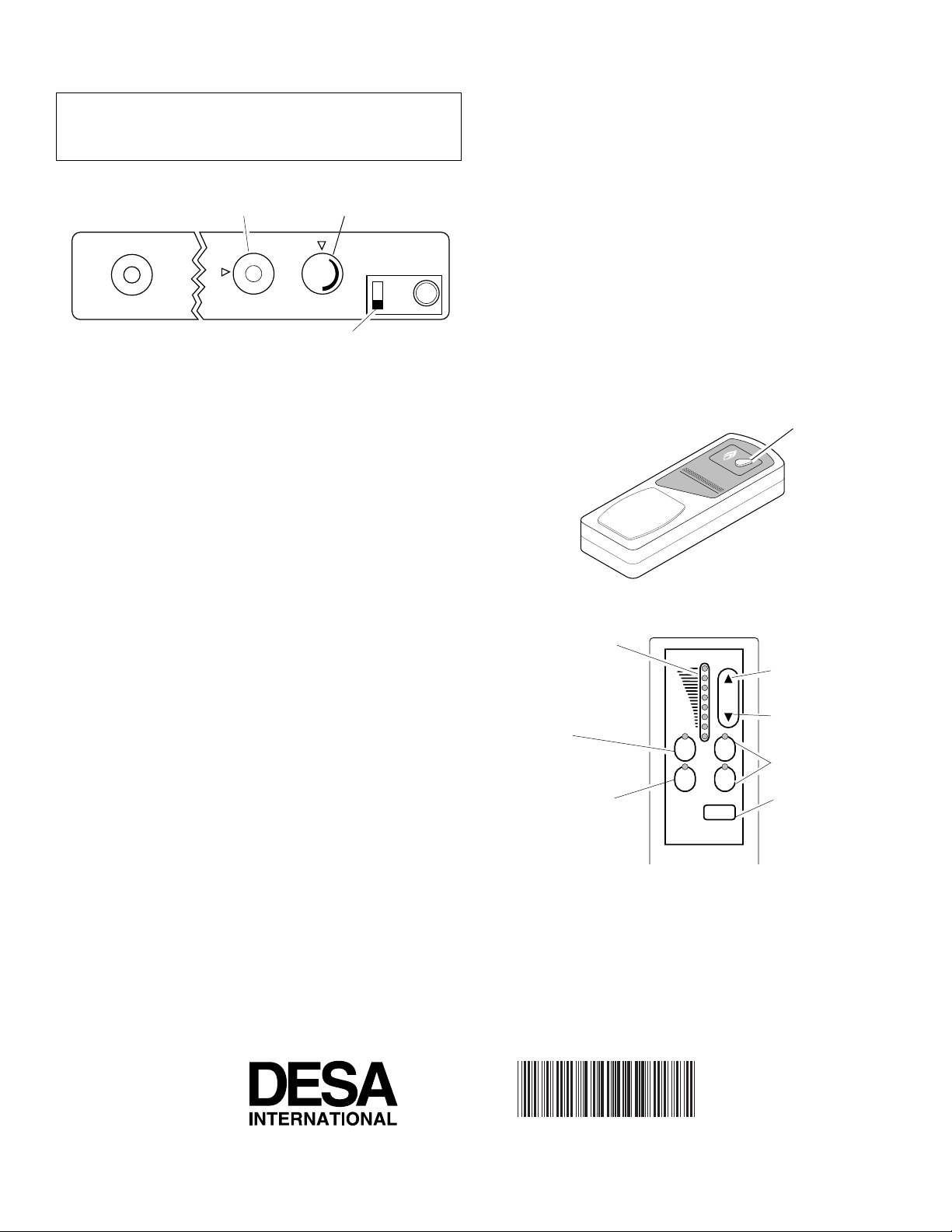
REMOTE OPERATION
NOTICE: You must light the pilot before using the
hand-held remote control unit. See
tions
in your owner’s manual.
Control Knob in
On Position
N
O
O
F
F
T
O
P
I
L
Selector Switch
in Remote Position
Figure 6 - Setting the Selector Switch, Control Knob, and Flame
Adjustment Knob for Remote Operation
1. After lighting, let pilot flame burn for about one minute.
This is required before the burner(s) will turn on. Turn
control knob to ON position. Adjust flame adjustment knob
anywhere between HI and LO. Slide the selector switch to
the REMOTE position.
Note:
hand-held remote ON button was on when selector switch
was last turned off. You can now turn the burner(s) on and
off with the hand-held remote control unit.
IMPORTANT:
Do not leave the selector switch in the A UTO
position on the handset when the pilot is not lit. This will
shorten the battery life.
IMPORTANT:
Be sure to press the ON/OFF buttons on
the hand-held remote control unit for up to 3 seconds to
assure proper operation.
2a. GHRC Series Operation: Press the control b utton on the
hand held remote to turn burner on. Pr ess the control b utton again to turn burner off (see Figure 7).
2b. GHRCT Series Operation: Select the MAN(manual) or
AUTO button on the hand-held remote control unit (see
Figure 8).
• In manual mode, turn burners on or off by pr essing the
ON or OFF buttons on the hand-held remote control unit.
• In auto mode, the room temperature is controlled by the
thermostat in the hand-held remote control unit. To increase the room temperature, pr ess the top arro w of the
TEMP button. To lower the room temperature, press the
bottom arrow of the TEMP button. At higher settings
the heater will run longer.
IMPORTANT:
This remote control has been specially engineered to take an air temperature sample every 5.5
minutes in the auto mode. It will not respond immediately to the temperature setting being turned up or down.
Lighting Instruc-
Flame Adjustment Knob
O
L
H
I
ON
OFF
REMOTE
The burner(s) may light if
IMPORTANT:
The hand-held remote control unit must be
in the vicinity of the heater. Do not keep the hand-held
remote control unit too close to the heater. The thermostat
on the hand-held remote control unit will heat up too
quickly and turn the heater off. Ideally the hand-held remote control unit should be located in a central part of the
room where the heater is located.
3. Use the STATUS button on the hand-held remote control
unit to see the operation mode being used and the temperature setting selected. A red light will come on beside
the operation mode being used when the status button is
pressed.
4. To turn the burners off when operating in the manual
mode, press the OFF button. If operating in the auto mode,
press the MAN button, then press the OFF button. The
pilot will remain lit.
IMPORTANT:
T o turn the pilot off, manually tur n the con-
trol knob on the heater to the OFF position.
Turns Burner(s)
On and Off
Figure 7 - GHRC Hand-Held Remote Control Unit
Shows Temperature
Setting
Allows Burner(s) to
be Turned On and Off
with the Hand-Held
Remote Unit
The Log Heater Will
Automatically Cycle
Between Pilot and
HI
LO
MAN ON
AUTO OFF
STATUS
Increases Room
Temperature
TEMP
Decreases Room
Temperature
Turns Burner(s)
On and Off
Shows Current
Operation Mode
the Heat Setting that
has been Selected
Figure 8 - GHRCT Hand-Held Remote Control Unit
Selections
Note:
For customer service, call the manufacturer at 1-888-301-
0440 or visit their web site at www.trackingtech.com.
2701 Industrial Drive
P.O. Box 90004
Bowling Green, KY 42102-9004
103962 01
NOT A UPC
103962-01
REV. D
06/99
 Loading...