

Page 1
®
,
,
,
,
,
,
,
,
,
,
,
,
,
,
,
,
,
,
,
,
,
,
,
,
,
,
,
,
,
,
,
,
,
,
,
,
,
,
,
,
,
,
,
,
,
,
,
,
,
,
,
,
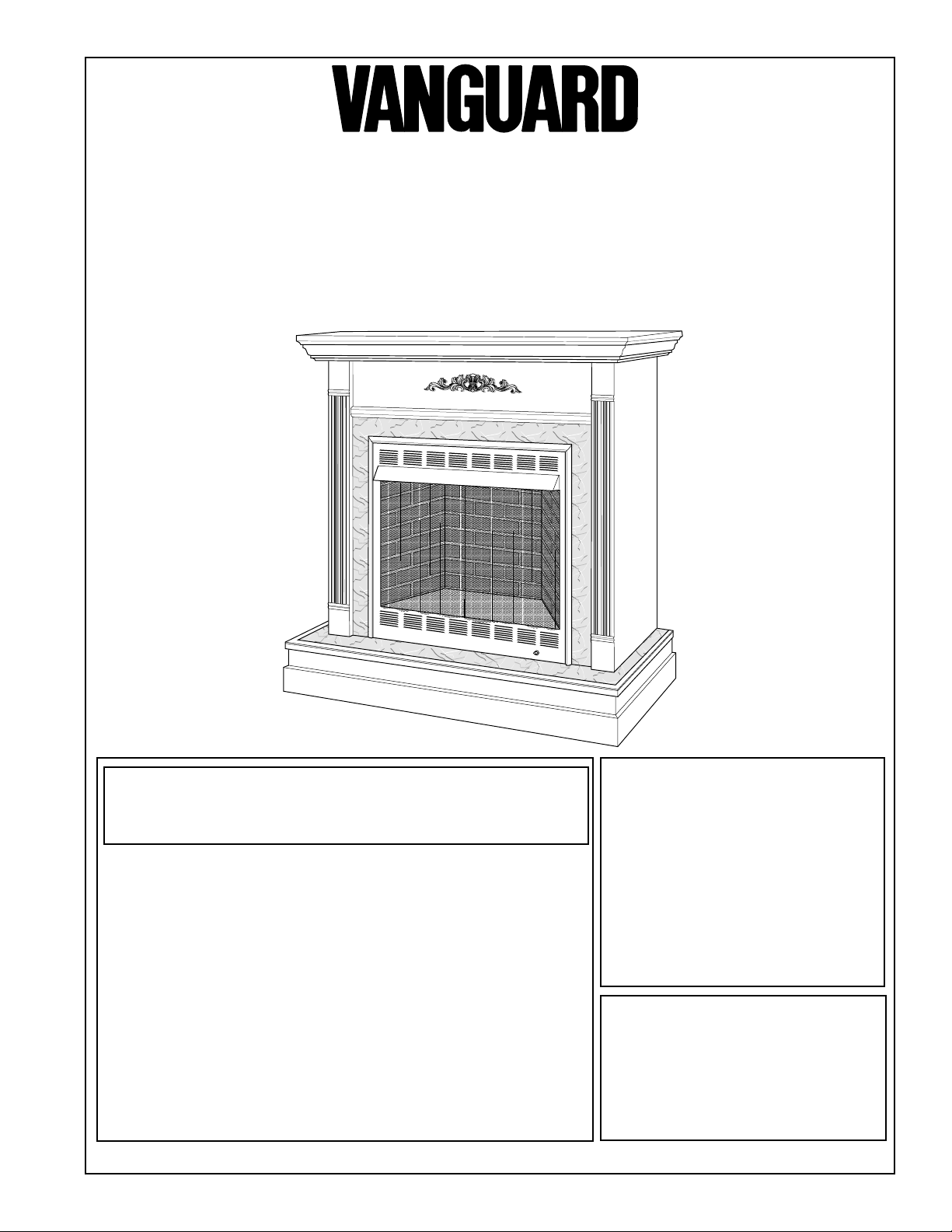
UNVENTED (VENT -FREE)
™
LogMate II
This firebox may be installed in an aftermarket* manufactured (mobile) home,
where not prohibited by state or local codes.
* Aftermarket: Completion of sale, not for purpose of resale, from the manufacturer
(i.e. Installation of this product is permitted after the manufactured (mobile) home is sited).
FIREBOX
OWNER’S
FB32C (shown)
Circulating
OPERATION
AND
INSTALLATION
MANUAL
WARNING: If the information in this manual is not followed
exactly, a fire or explosion may result causing property
damage, personal injury, or loss of life.
— Do not store or use gasoline or other flammable vapors
and liquids in the vicinity of this or any other appliance.
— WHAT TO DO IF YOU SMELL GAS
• Do not try to light any appliance.
• Do not touch any electrical switch; do not use any
phone in your building.
• Immediately call your gas supplier from a neighbor’s
phone. Follow the gas supplier’s instructions.
• If you cannot reach your gas supplier, call the fire
department.
— Installation and service must be performed by a qualified installer, service agency, or the gas supplier.
Save this manual for future reference.
WARNING: Improper installation, adjustment, alteration, service, or maintenance can cause
injury or property damage. Refer to this manual for correct
installation and operational procedures. For assistance or additional information consult a qualified installer, service agency, or
the gas supplier.
WARNING: The FB32C and
FB32NC Fireboxes are to be used
only with certain vent-free gas
log heaters (see Table 1). Do not
burn wood or other materials in
these fireboxes.
Louvered and
FB32NC
Noncirculating
Smooth Face
Models
Shown with optional
cabinet mantel, hearth
base, brass trim, and
marble trim accessories.
Page 2
CONTENTS
SECTION PAGE
Safety Information..........................................................................................................2
Product Specifications .................................................................................................... 4
Local Codes .................................................................................................................... 5
Unpacking.......................................................................................................................5
Product Features .............................................................................................................6
Locating Firebox ............................................................................................................6
Air for Combustion and Ventilation...............................................................................6
Installing .......................................................................................................................10
Installation Clearances ..........................................................................................10
Installing Blower Accessory ................................................................................. 12
Installing Log Heater in Firebox ...........................................................................13
Installing Fireplace Hood ......................................................................................14
Installing Fireplace Screen ....................................................................................14
Firebox Installation Using Optional Accessory Mantels ......................................15
Built-In Firebox Installation ..................................................................................17
Technical Service .........................................................................................................19
Replacement Parts ........................................................................................................19
Accessories ...................................................................................................................20
Illustrated Parts Lists .............................................................................................. 22-25
Warranty Information ....................................................................................Back Cover
SAFETY
INFORMATION
W ARNINGS
WARNING ICON G 001
IMPORTANT: Read this owner’s manual carefully and completely before
trying to assemble, operate, or service this firebox. Improper use of this
firebox can cause serious injury or death from burns, fire, explosion,
electrical shock, and carbon monoxide poisoning.
TABLE 1
For use with vent-free gas log heater models:
VANGUARD
VL18N/P
VL18NT(A)/PT(A)
VL18NV/PV
VL24N/P
VL24NT(A)/PT(A)
VL24NV/PV
VS24NV(A,B)
VS24PV(A,B)
VS18NR/PR
VS18NV(B)/PV(B)
VS24NR/PR
VYS18N/P
VYS24N/P
®
VYD18N/P
VYD24N/P
VYBD18N/P
VYBD24N/P
VS24NTA
VS24PTA
VS18NTA
VS18PTA
VLH26N
VLH22P
VLH39N
VLH31P
COMFORT FLAME
CF18N
CF18P
CF18NT(A)
CF18PT(A)
CF24N
CF24P
CF24NT(A)
CF24PT(A)
CFS24NV(A,B)
CFS24PV(A,B)
®
CFS18NV(B)
CFS18PV(B)
CFYS18N
CFYS18P
CFYS24N
CFYS24P
CFLH26N
CFLH22P
CFLH39N
CFLH31P
2
103296
Page 3

SAFETY
INFORMATION
Continued
W ARNINGS
WARNING: Any change to this firebox or its controls can be dangerous.
1. This firebox shall not be installed in a bedroom or bathroom.
2. Never install the firebox
• in a recreational vehicle
• where curtains, furniture, clothing, or other flammable objects are less than
36 inches from the front, top, or sides of the firebox
• in high traffic areas
• in windy or drafty areas
3. Do not use this firebox as a wood-burning fireplace. Use only the logs specified in Table 1, page 2.
4. Do not add extra logs or ornaments such as pine cones, vermiculite, or rock
wool. Using these added items can cause sooting.
5. You must operate this fireplace with the fireplace screen, hood, and brick liner
in place. Make sure these parts are in place before running firebox.
6. Do not allow fans to blow directly into the firebox. Avoid any drafts that alter
burner flame patterns. Ceiling fans can create drafts that alter burner flame
patterns. Altered burner patterns can cause sooting.
7. Do not use a blower insert, heat exchanger insert or other accessory not
approved for use with this heater. Do not use blower accessory with Model
FB32NC.
8. Vent-free gas log heaters installed in these fireboxes require fresh air ventilation
to run properly. See Air for Combustion and Ventilation, pages 6 through 9.
9. Do not run firebox
• where flammable liquids or vapors are used or stored
• under dusty conditions
10.Do not use this firebox to cook food or burn paper or other objects.
11.Never place any objects in the firebox or on logs.
12.Firebox front and screen becomes very hot when running firebox. Keep
children and adults away from hot surfaces to avoid burns or clothing ignition.
Firebox will remain hot for a time after shut-down. Allow surfaces to cool
before touching.
13.Carefully supervise young children when they are in the room with firebox.
14.Turn firebox off and let cool before servicing. Only a qualified service person
should service and repair firebox.
15.Operating firebox above elevations of 4,500 feet could cause pilot outage.
Continued
103296
3
Page 4
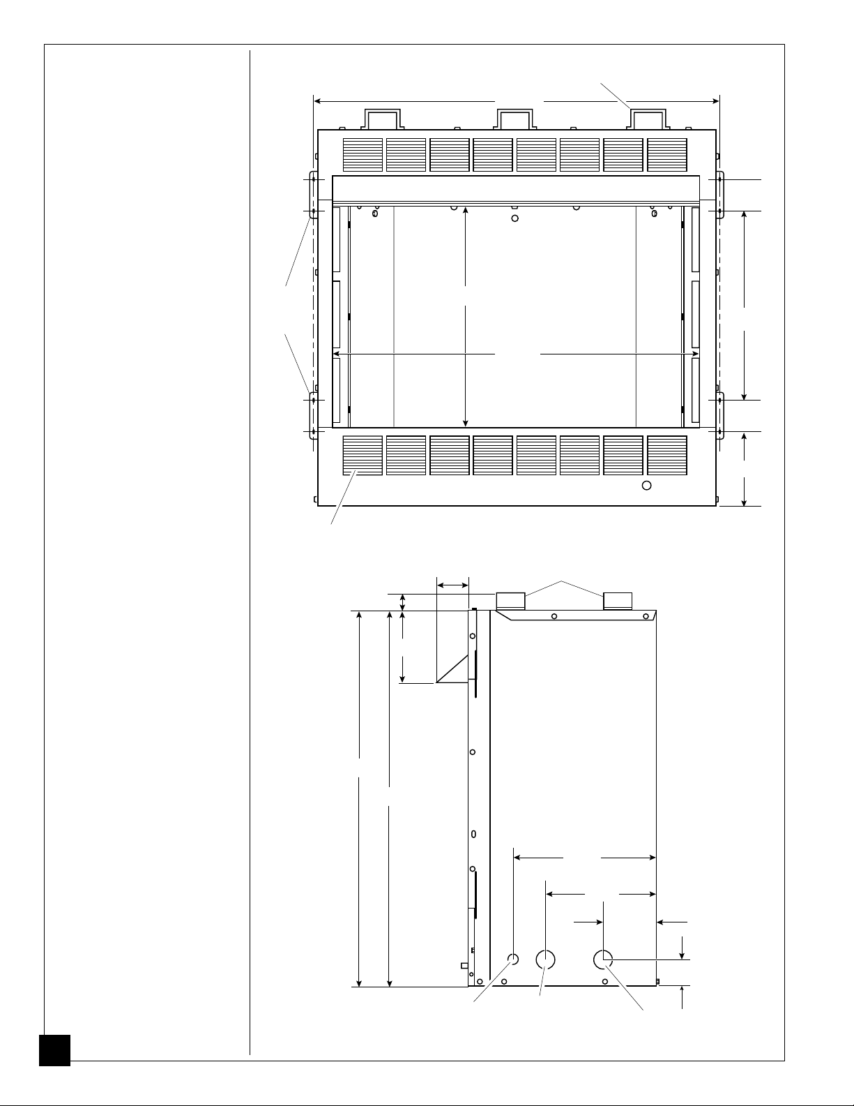
PRODUCT
SPECIFICATIONS
Standoffs (Model FB32NC only)
35 1/16"
2 3/4"
Built-in
Nailing
Flanges
Louvers
(Model FB32C only)
19 3/8"
16 1/4"
31 3/4"
2 3/4"
6 3/8"
Figure 1 - Firebox Front View
Standoffs
(Model FB32NC only)
2 3/4"
1 1/2"
6"
33 11/16"
32 3/16"
12 1/2"
9 3/4"
4 5/8"
2 1/2"
Electrical
Access Hole
4
Figure 2 - Firebox Side View
Electrical Access
Hole with Bushing
Gas Line Access
103296
Page 5
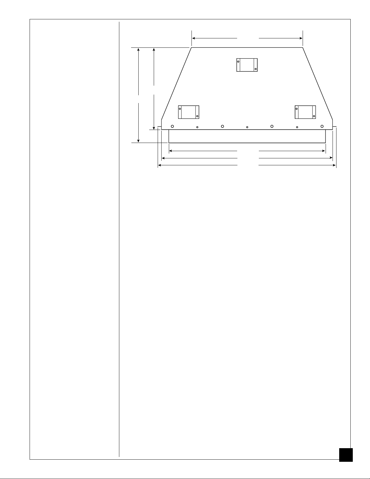
PRODUCT
SPECIFICATIONS
Continued
22 1/2"
16 1/2"
19 1/4"
31 5/8"
34 3/8"
35 5/8"
Figure 3 - Firebox Side View
LOCAL CODES
UNPACKING
Install and use fireplace with care. Follow all local codes. In the absence of local
codes, use the latest edition of The National Fuel Gas Code ANSI Z223.1, also
known as NFPA 54*. Firebox must be electrically grounded in accordance with
the National Electrical Code, ANSI/NFPA70 (latest edition).
*Available from:
American National Standards Institute, Inc.
1430 Broadway
New York, NY 10018
National Fire Protection Association, Inc.
Batterymarch Park
Quincy, MA 02269
1. Cut banding along lower edge of carton. Unfold bottom flaps and lift upper
carton off of firebox. Pull carton away and discard.
2. Check carton contents for the following:
Screen assembly
Screen support rod
Hood
Hardware and parts bag containing the following:
Owners Operation and Installation Manual
Flexible gas connector
2 - Black #10 x 3/8" Phillips screws
3 - Zinc #10 x 1/2" shouldered hex screws
2 - Black #10 x 5/8" shouldered hex screws
If any items are missing, inform dealer where you bought firebox.
3. Check all items for any shipping damage. If damaged, promptly inform dealer
where you bought firebox.
103296
5
Page 6
PRODUCT
FEATURES
Operation
This firebox is designed to accept all gas log heaters listed in Table 1, page 2. It requires
no outside venting or chimney making installation easy and inexpensive. When used
without the blower (model FB32C only), the firebox requires no electricity making it
ideal for emergency back-up heat.
Blower Accessory
The FB32C firebox will accept the GA3500A accessory. The variable blower
allows you to select the fan speed you desire. The blower circulates heated air
from the firebox into the room. Use of blower is optional.
LOCATING
FIREBOX
AIR FOR
COMBUSTION
AND
VENTILATION
Planning
Plan where you will install the firebox. This will save time and money later when
you install the firebox. Before installation, consider the following:
1. Where the firebox will be located. Allow for wall and ceiling clearances (see
Installation Clearances, page 10).
2. Everything needed to complete installation.
3. These models CANNOT be installed in a bedroom or bathroom.
4. Proper air for combustion and ventilation (see below).
W ARNING
This firebox shall not be installed in a confined space unless
provisions are provided for adequate combustion and ventilation
air. Read the following instructions to insure proper fresh air for
this and other fuel-burning appliances in your home.
Today’s homes are built more energy efficient than ever. New materials, increased
insulation, and new construction methods help reduce heat loss in homes. Home
owners weather strip and caulk around windows and doors to keep the cold air out
and the warm air in. During heating months, home owners want their homes as
airtight as possible.
While it is good to make your home energy efficient, your home needs to breathe.
Fresh air must enter your home. All fuel-burning appliances need fresh air for
proper combustion and ventilation.
Exhaust fans, fireboxs, clothes dryers, and fuel burning appliances draw air from
the house to operate. You must provide adequate fresh air for these appliances.
This will insure proper venting of vented fuel-burning appliances.
6
103296
Page 7

AIR FOR
COMBUSTION
AND
VENTILATION
Continued
PROVIDING ADEQUATE VENTILATION
The following is exerpts from National Fuel Gas Code. NFPA 54/ANSI Z223.1,
Section 5.3, Air for Combustion and Ventilation.
All spaces in homes fall into one of the three following ventilation classifications:
1. Unusually Tight Contruction; 2. Unconfined Space; 3. Confined Space.
The information on pages 6 through 9 will help you classify your space and provide
adequate ventilation.
Unusually Tight Construction
The air that leaks around doors and windows may provide enough fresh air for
combustion and ventilation. However, in buildings of unusually tight construction,
you must provide additional fresh air.
Unusually tight construction is defined as construction where:
a. walls and ceilings exposed to the outside atmosphere have a continu-
ous water vapor retarder with a rating of one perm or less with open-
ings gasketed or sealed
b. weather stripping has been added on openable windows and doors
c. caulking or sealants are applied to areas such as joints around window
and door frames, between sole plates and floors, between wall-ceiling
joints, between wall panels, at penetrations for plumbing, electrical, and
gas lines, and at other openings.
If your home meets all of the three criteria above, you must provide additional fresh air. See
If your home does not meet all of the three criteria above, proceed to page 8.
Ventilation Air From Outdoors
and
, page 9
and
.
Unconfined Space
The National Fuel Gas Code, ANSIZ223.1, 1992, Section 5.3 defines unconfined
space as having a minimum air volume of 50 cubic feet (127 cubic cm) for each
1000 Btu/Hr input rating of all appliances in the space (cubic feet equals length
x width x height of space). Include adjoining rooms only if there are doorless
passageways or ventilation grills between the rooms.
Confined Space
The National Fuel Gas Code, ANSIZ223.1, 1992, Section 5.3 defines confined
space as having an air volume of less than 50 cubic feet (127 cubic cm) for each
1000 Btu/Hr input rating of all appliances in the space (cubic feet equals length
x width x height of space). Include adjoining rooms only if there are doorless
passageways or ventilation grills between the rooms.
Continued
103296
7
Page 8
AIR FOR
COMBUSTION
AND
VENTILATION
Continued
DETERMINING AIR FLOW FOR FIREBOX LOCATION
Determining if You Have a Confined or Unconfined Space
Use this work sheet to determine if you have a confined or unconfined space.
Space: Includes the room in which you will install firebox plus any adjoining rooms
with doorless passageways or ventilation grills between the rooms.
1. Determine the volume of the space (length x width x height).
Length x Width x Height = ___________________ cu. ft. (volume of space)
Example:
If additional ventilation to adjoining room is supplied with grills or openings, add the
volume of these rooms to the total volume of the space.
2. Divide the space volume by 50 cubic feet to determine the maximum Btu/Hr the space
can support.
____________ (volume of space) ÷ 50 cu. ft. = (Maximum Btu/Hr the space can support)
Example:
3. Add the Btu/Hr of all fuel burning appliances in the space.
Example:
* Do not include direct-vent gas appliances. Direct-vent draws combustion air from the
outdoors and vents to the outdoors.
4. Compare the maximum Btu/Hr the space can support with the actual amount of Btu/Hr
used.
_________________ Btu/Hr (maximum the space can support)
_________________ Btu/Hr (actual amount of Btu/Hr used)
Example:
The space in the above example is a confined space because the actual Btu/Hr used is more
than the maximum Btu/Hr the space can support. You must provide additional fresh air.
Your options are as follows:
A. Rework work sheet, adding the space of an adjoining room. If the extra space pro-
vides an unconfined space, remove door to adjoining room or add ventilation grills
between rooms. See Ventilation Air from Inside Building, page 9.
B. Vent room directly to the outdoors. See Ventilation Air from Outdoors, page 9.
C. Install a lower Btu/Hr firebox, if lower Btu/Hr size makes room unconfined.
If the actual Btu/Hr used is less than the maximum Btu/Hr the space can support, the
space is an unconfined space. You will need no additional fresh air ventilation.
Space size 22 ft. (length) x 18 ft. (width) x 8 ft. (ceiling height) =
3168 cu. ft. (volume of space)
3168 cu. ft. (volume of space) ÷ 50 cu. ft. = 63.3 or 63,300 (maximum
Btu/Hr the space can support)
Vent-free firebox ___________________ Btu/Hr
Gas water heater* ___________________ Btu/Hr
Gas furnace ___________________ Btu/Hr
Vented gas heater ___________________ Btu/Hr
Gas firebox logs ___________________ Btu/Hr
Other gas appliances* + ___________________ Btu/Hr
Total = ___________________ Btu/Hr
Gas water heater 40,000 Btu/Hr
Vent-free firebox with log heater + 39,000 Btu/Hr
Total = 79,000 Btu/Hr
63,300 Btu/Hr (maximum the space can support)
79,000 Btu/Hr (actual amount of Btu/Hr used)
W ARNING
If the area in which the firebox and gas log heater may be operated is smaller than that defined as an unconfined space, provide
adequate combustion and ventilation air by one of the methods
described in the
8
Section 5.3.
National Fuel Gas Code, ANSI Z223.1, 1992,
103296
Page 9
AIR FOR
COMBUSTION
AND
VENTILATION
Continued
VENTILATION AIR
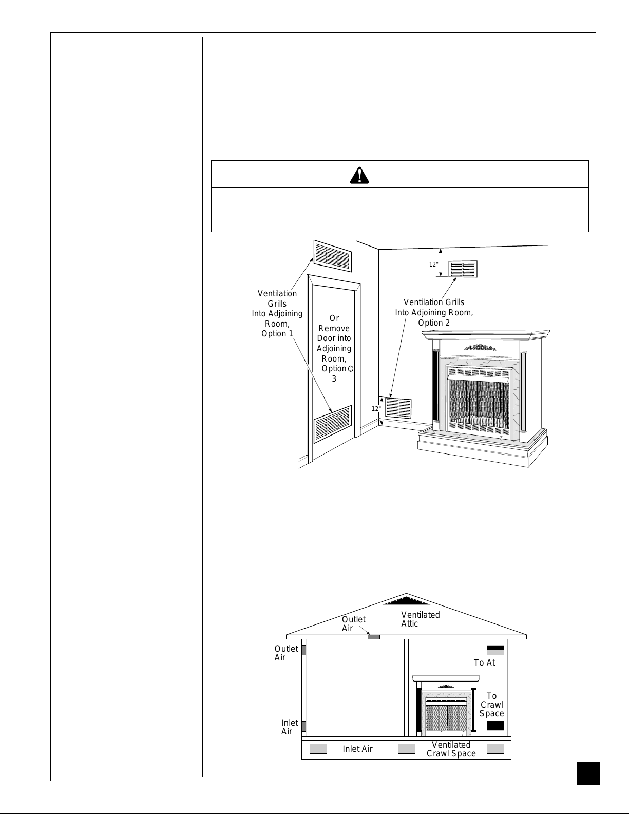
Ventilation Air From Inside Building
This fresh air would come from an adjoining unconfined space. When ventilating to an
adjoining unconfined space, you must provide two permanent openings: one within 12" of the
ceiling and one within 12" of the floor on the wall connecting the two spaces (see options 1
and 2, Figure 4). You can also remove door into adjoining room (see option 3, Figure 4).
Follow the National Fuel Gas Code NFPA 54/ANSI Z223.1, Section 5.3, Air for Combustion
and Ventilation for required size of ventilation grills or ducts.
W ARNING
Rework worksheet, adding the space of the adjoining unconfined
space.
appliances in both spaces.
The combined spaces must have enough fresh air to supply all
12"
Ventilation
Grills
Into Adjoining
Room,
Option 1
Or
Remove
Door into
Adjoining
Room,
Option
3
12"
Ventilation Grills
Into Adjoining Room,
Option 2
Figure 4 - Ventilation Air from Inside Building
Ventilation Air From Outdoors
Provide extra fresh air by using ventilation grills or ducts. You must provide two permanent openings: one within 12" of the ceiling and one within 12" of the floor. Connect
these items directly to the outdoors or spaces open to the outdoors. These spaces include
attics and crawl spaces.
IMPORTANT:
thermostat-controlled power vent. Heated air entering the attic will activate the power
vent.
Do not provide openings for inlet or outlet air into attic if attic has a
103296
Outlet
Air
Outlet
Air
Inlet
Air
Inlet Air
Ventilated
Attic
Ventilated
Crawl Space
Figure 5 - Ventilation Air from Outdoors
To Attic
To
Crawl
Space
9
Page 10

INSTALLING
NOTICE
A qualified service person must install firebox. Follow all local
codes.
W ARNING
Never install the firebox
• in a bedroom or bathroom
• in a recreational vehicle
• where curtains, furniture, clothing, or other flammable
objects are less than 36 inches from the front, top, or sides
of the firebox
• in high traffic areas
• in windy or drafty areas
CAUTION
Log heaters installed in this firebox create warm air currents.
These currents move heat to wall surfaces next to firebox. Installing firebox next to vinyl or cloth wall coverings or operating
firebox where impurities in the air (such as tobacco smoke) exist,
may discolor walls.
IMPORTANT:
beneficial, installing firebox in rooms without enough ventilation air may cause
mildew to form from too much moisture. See Air for Combustion and Ventilation,
pages 6 through 9.
IMPORTANT:
work properly.
Vent-free gas log heaters add moisture to the air . Although this is
Make sure the firebox is level. If firebox is not level, log set will not
INSTALLATION CLEARANCES
W ARNING
Maintain the minimum clearances. If you can, provide greater
clearances from floor, ceiling, and adjoining wall.
Carefully follow the instructions below. This will ensure safe installation.
Minimum Wall and Ceiling Clearances (see Figure 6, page 11)
A. Clearances from the side of the firebox opening to any combustible wall should not
be less than 16 inches for a cabinet mantel or 12 inches for a corner installation.
B. Clearances from the top of the firebox opening to the ceiling should not be less
than 42 inches.
10
103296
Page 11

INSTALLING
Continued
Mantel Clearances for Conventional Installation
MINIMUM CLEARANCE
Side Wall - 16 " Cabinet and
42"
Note: Clearances are the
same if using optional
cabinet mantel or built-in
Face Mantel
Ceiling - 42" Corner Mantel
Floor - 0"
installation.
16"
Face or
Cabinet
Mantel
12"
Corner
Mantel
Figure 6 - Minimum Clearance to Wall and Ceiling
Mantel Clearances for Built-In Installation
If placing custom mantel above built-in firebox, you must meet minimum clearance
between mantel shelf and top of firebox opening.
Mantel Shelf
10"
8"
6"
2
1
/2
"
20" 24
Distances to
Underside of
Mantel
1
/2
" 27
1
/2
" 30"
Underside of
Mantel Shelf
All minimum
distances are
in inches
Top of
Fireplace
Opening
103296
Figure 7 - Minimum Mantel Clearances for Built-In Installation
If your installation does not meet the above minimum clearances, you must:
• raise the mantel to an acceptable height, OR
• remove the mantel.
11
Page 12

INSTALLING
Continued
INSTALLING BLOWER ACCESSORY (Model FB32C only)
You may install blower accessory GA3500A with conventional installation (page
15) or with built-in installation (page 17) with model FB32C only. To install
blower accessory, see instruction sheet included with the kit.
Conventional Installation of Blower Accessory
1. Install blower assembly per instruction sheet included in blower accessory kit.
2. Before replacing bottom of firebox, route blower power cord through hole in
support bracket in bottom of firebox and through hole in side of firebox to
grounded, three-prong 120 volt electrical outlet (see Figure 8). Plug electrical
cord into outlet.
3. Replace bottom of firebox.
Electrical
Blower
Support Bracket Opening
Blower Power Cord
Figure 8 - Routing Blower Accessory Power Cord for
Conventional Installation
Outlet
Side Opening
NOTICE
A certified electrician must connect electrical wiring to duplex
outlet for built-in installation. Follow all local codes.
Built-In Installation of Blower Accessory
1. Install blower assembly per instruction sheet included.
2. Before replacing bottom of firebox, remove screw holding duplex outlet to the
support bracket in the bottom of firebox. Remove duplex outlet.
3. Clamp electrical cable into firebox through smallest hole using strain relief provided.
4. Route wires from electrical box through hole in side of heater and hole in
support bracket (see Figure 9).
5. Connect wires from the electrical box to duplex outlet. Match wire colors to
those indicated on duplex outlet. Be sure to connect ground wire.
6. Replace duplex outlet with screw.
7. Plug blower power cord into duplex outlet.
8. Replace bottom of firebox.
Blower
Support bracket
Cables From
Electrical
Source
Duplex Outlet
12
Screw
Blower Power Cord
Figure 9 - Routing Blower Accessory Power Cord for Built-In Installation
103296
Page 13

INSTALLING
INSTALLING LOG HEATER IN FIREBOX
Continued
CAUTION
Do not pick up log base assembly by burners. This could damage
burners. Only handle base by grates.
1. Remove four screws holding firebox bottom in place.
2. Lift and remove firebox bottom (see Figure 10).
3. If installing GA3500A Blower Accessory (Model FB32C only), see Installing
Blower Accessory, page 12.
Figure 10 - Removing Firebox Bottom
4. Route flexible gas line from manual shutoff valve into firebox through side.
NOTICE
Most building codes do not permit concealed gas connections. A
flexible gas line is provided to allow accessibility from the firebox.
The flexible gas supply line connection to the manual shutoff
valve should be accessible.
5. Attach gas log heater base to firebox bottom with four screws included with
base (see Installing Heater Base Assembly in log set owner’s manual).
6. Replace firebox bottom and secure with screws.
IMPORTANT:
VL24NT(A)/PT(A), VS24NV(A)/PV(A), VS18NV/PV, VS24NTA/PTA,
VS18NTA/PTA, CF18N/P, CF18NT(A)/PT(A), CF24N/P, CF24NT(A)/PT(A),
CFS24NV(A)/PV(A), CF18NV/PV, CF24NTA/PTA, or CF18NTA/PTA gas log
heater, locate two mounting brackets included with appliance. Measure these
brackets. If overall length is 9 1/4", cut 2" off rear of each bracket with hacksaw
(see Figure 11).
Screws
If installing a VL18N/P, VL18NT(A)/PT(A), VL24N/P,
Heater Base
Mounting
Bracket
Cut to
7 1/4"
Length
Firebox Bottom
103296
Figure 11 - Cutting Brackets
13
Page 14

INSTALLING
Continued
INST ALLING FIREPLACE HOOD
1. Attach three zinc-colored shoulder screws to back of hood.
2. Insert hood into hood-mounting slots on firebox.
3. Hold hood in place. Insert two black Phillips screws through bottom of
hood and tighten.
Hood
Hood Mounting Slot
Shoulder
Screw
Screw
Figure 12 - Installing Fireplace Hood
INST ALLING FIREPLACE SCREEN
1. Insert each rod through nine rings located at top of screen.
2. Insert first rod into rear hole in left side of firebox. Fasten rod to rear
hole near center of firebox using black shoulder screw.
3. Insert other rod into front hole on right side of firebox and fasten using
remaining shoulder screw.
Rear Hole
Front Hole
Rod
Ring
Screw
14
Screen
Figure 13 - Installing Fireplace Screen
(Shown Without Fireplace Hood for Clarity)
103296
Page 15

INSTALLING
Continued
FIREBOX INSTALLATION USING OPTIONAL ACCESSORY MANTELS
This firebox may be installed using the corner or cabinet mantel with hearth base
accessories against a wall in your home. You must use a GA6090 brass trim kit to
properly install the mantel accessories (see Accessories, pages 20 and 21). Follow
the instructions below to install the firebox in this manner.
Note:
The instructions below show installation using GM100F/GM101U series
cabinet mantels and the G3000F/G3001U series hearth base accessories. The
hearth base accessory shown is optional for this installation. You can install
firebox and cabinet mantel directly on the floor. The corner mantel and face
mantel accessories cannot be installed with the G3000F/G3001U series hearth
base. You must install corner and face mantels directly on the floor. If mounting
firebox and cabinet mantel to the floor or using face mantel or corner mantel, an
optional G3005 Slim Base kit may be installed.
GM401U series face mantel accessory, a wall recess opening will be needed. See
installation instructions for GM400F/GM401U series mantel accessory.
1. Assemble cabinet mantel, hearth base, GA6090 brass trim, and trim accesso-
ries. Assembly instructions are included with each accessory.
2. If using an optional GA3500A blower (FB32C model only), install a properly
grounded, 120 volt three-prong electrical outlet at firebox location if an outlet
is not there. If possible, locate outlet so cabinet mantel will cover it when
installed (see Figure 15, page 16).
3. Install gas piping to firebox location. This installation includes an approved
flexible gas line (if allowed by local codes) and a manual shutoff valve. The
flexible gas line must be the last item installed on the gas piping. See Connect-
ing to Gas Supply in your log set owner’s manual.
Note:
If using the GM400F/
NOTICE
A qualified service person must connect firebox to gas supply.
Follow all local codes.
4. Place hearth base accessory against wall at installation location. Cut an access
hole in hearth top to run flexible gas line to firebox (see Figure 14). Make sure to
locate access hole so cabinet mantel will cover it when installed.
secure base to floor using wood screws. Countersink screw heads and putty over.
Hearth Base
Figure 14 - Placing Hearth Base Accessory Against Wall
Flexible Gas Line
Electrical Outlet
Note:
You can
Gas Line Access
Hole
103296
Continued
15
Page 16

INSTALLING
Continued
5. Route flexible gas line through access hole in hearth base.
6. Center cabinet mantel on hearth base (see Figure 15). Make sure mantel is
flush against wall.
Cabinet Mantel
Figure 15 - Installing Cabinet Mantel
7. Break off nailing flanges (see Figure 16) with hammer or pliers.
If installing Brass Trim Kit GA6090, see instructions included with brass trim
accessory.
Figure 16 - Location of Nailing Flanges
8. Place cardboard or other protective material on top of hearth base. Carefully set
firebox on protective material, with back of firebox inside mantel opening.
9. Attach flexible gas line to log set. See Connecting to Gas Supply in your log
set owner’s manual.
IMPORTANT:
Nailing Flanges
16
103296
Page 17

INSTALLING
Continued
10. If installing GA3500A blower (FB32C firebox only), route blower electrical
cord through bushing in right side firebox support and bushing in side access
opening of firebox. Plug electrical cord into electrical outlet. See Installing
Blower Accessory, page 12.
11. Carefully insert firebox into cabinet mantel. Be careful not to scratch or damage
hearth base, cabinet mantel, or any laminate trim on hearth base. Remove
protective material from top of hearth base and from front of firebox (if any).
12. If using optional GA6090 brass trim kit, install the trim after final finishing
and/or painting of wall. See instructions included with brass trim accessory for
attaching brass trim.
13. Check all gas connections for leaks. See Checking Gas Connections in log set
owner's manual.
Figure 17 - Inserting Firebox Into Cabinet Mantel
BUILT-IN FIREBOX INSTALLATION
Built-in installation of this firebox involves installing firebox into a framed-in
enclosure. This makes the front of firebox flush with wall. If installing a mantel above
the firebox, but you must follow the clearances shown in Figure 7, page 11. Follow
the instructions below to install the firebox in this manner.
Height Front Width Depth
Model # Actual Framing Actual Framing Actual Framing
FB32C 32
FB32NC 33
1. Frame in rough opening. Use dimensions shown in Figure 18 for the rough
opening.
3
/8" 33" 34 5/16" 35 1/2" 16 11/16" 17 3/4"
11
/16" 34 1/4" 34 5/16" 35 1/2" 16 11/16" 17 3/4"
17 3/4"
33" (FB32C)
34 1/4" (FB32NC)
103296
35 1/2"
Figure 18 - Rough Opening for Installing in Wall
Continued
17
Page 18

INSTALLING
39 3/8"
27 7/8"
55 5/8"
35 1/2"
Continued
If installing in a corner, use dimensions shown in Figure 19 for the rough
opening. The height is 33" (FB32C) or 34 1/4" (FB32NC), which is the same
as the wall opening in Figure 18.
Figure 19 - Rough Opening for Installing in Corner
2. Install gas piping to firebox location. This installation includes an approved
flexible gas line (if allowed by local codes) after the manual shutoff valve. The
flexible gas line must be the last item installed on the gas piping. See Connect-
ing to Gas Supply in log set owner’s manual.
3. Carefully set firebox in front of rough opening with back of firebox inside wall
opening.
IMPORTANT:
If installing Brass Trim Kit GA6090, see instructions
included with brass trim accessory. You must install shoulder screws now.
4. If using GA3500A blower accessory (Model FB32C only), see Installing
Blower Accessory for built-in installation, page 12.
5. Attach flexible gas line to log set. See Connecting to Gas Supply in log set
owner’s manual.
6. Carefully insert firebox into rough opening.
7. Attach firebox to wall studs using nails or wood screws through holes in
nailing flange (see Figure 20).
8. Check all gas connections for leaks. See Checking Gas Connections in log set
owner’s manual.
9. If using optional GA6090 brass trim kit, install the trim after final finishing
and/or painting of wall. See instructions included with brass trim accessory for
attaching brass trim.
18
Nails or Wood
Screws
Nailing Flanges
Figure 20 - Attaching Firebox to Wall Studs
103296
Page 19

TECHNICAL
SERVICE
REPLACEMENT
PARTS
You may have further questions about installation, operation, or troubleshooting.
If so, contact DESA International’s Technical Service Department at
1-800-DESA LOG (1-800-337-2564).
Note:
Use only original replacement parts. This will protect your warranty cover-
age for parts replaced under warranty.
Parts Under Warranty
Contact authorized dealers of this product. If they can’t supply original replacement part(s), call DESA International’s Technical Service Department at
1-800-DESA LOG (1-800-337-2564).
When calling DESA International, have ready
• your name
• your address
• model number of your firebox
• how firebox was malfunctioning
• type of gas used (propane or natural gas)
• purchase date
Usually, we will ask you to return the defective part to the factory.
Parts Not Under Warranty
Contact authorized dealers of this product. If they can’t supply original replacement part(s), call DESA International’s Parts Department at 1-800-972-7879 for
referral information.
When calling DESA International, have ready
• model number of your firebox
• the replacement part number
103296
19
Page 20

ACCESSORIES
Purchase these firebox accessories from your local dealer. If they can not supply
these accessories, call DESA International’s Sales Department at 1-800-432-2382
for information. You can also write to the address listed on the back page of this
manual.
CABINET MANTEL
GM100F Series - Walnut Finished
GM101U Series - Unfinished
Shown with optional base and laminate hearth and
mantel trim accessories.
Dimensions (WxHxD): 56-3/4" x 48-3/4" x 20-5/8"
FACE MANTEL
GM400F Series - Walnut Finished
GM401U Series - Unfinished
Shown with optional slim base.
Dimensions (WxHxD): 56-3/4" x 48-3/4" x 7"
HARDWOOD HEARTH BASE
G3000F Series - Walnut Finished
G3001U Series - Unfinished
The hearth base creates a handsome
riser for the firebox (cannot be used
with corner mantel or face mantel).
Dimensions (WxHxD): 58" x 6-1/2" x 28-9/16"
SLIM HEARTH BASE
G3005J - Jade Marble Laminate
G3005S - Sandstone Marble Laminate
G3005B - Black Onyx Marble Laminate
The slim hearth base allows you to further customize your firebox. Dimensions
(WxHxD): 41-7/8" x 5/8" x 10"
MANUAL SHUTOFF
VALVE - GA5010
Manual shutoff valve
with 1/8" NPT tap.
20
103296
Page 21

ACCESSORIES
Continued
CORNER MANTEL
GM200F Series - Walnut Finished
GM201U Series - Unfinished
Shown with optional laminate mantel trim accessory.
Dimensions (WxHxD): 60-7/8" x 48-3/4" x 34-5/8"
Hearth Base Trim
Mantel Trim
LAMINATE TRIM FOR HEARTH OR MANTEL
G3002J - Jade Marble Laminate Mantel Trim
G3003J - Jade Marble Laminate Hearth Base Trim
G3002S - Sandstone Marble Laminate Mantel Trim
G3003S - Sandstone Marble Laminate Hearth Base Trim
G3002B - Black Onyx Marble Laminate Trim
G3003B - Black Onyx Marble Laminate Hearth Base Trim
Mantel trim for cabinet, face, or corner mantel. Hearth base trim for hardwood
hearth bases.
BRASS TRIM ACCESSORY - GA6090
Required with all mantel accessories. Optional with built-in installation. Provides a
finished appearance covering rough and/or unfinished mantel edges.
BLOWER ACCESSORY - GA3500A
Use with Model FB32C only. The variable blower allows you to select the desired
speed. The blower circulates heated air from the fireplace into the room.
103296
21
Page 22

ILLUSTRATED
PARTS
BREAKDOWN
Model FB32NC
2
4
3
2
17
13
17
1
7
16
16
18
18
11
17
15
16
5
16
16
16
9
12
20
18
19
10
8
6
16
14
22
103296
Page 23

P ARTS LIST
Firebox
KEY
NO. PART NUMBER DESCRIPTION QTY.
1 101872-03 Firebox Top 1
2 101889-01 Firebrick Retainer 3
3 101929-01 Rear Firebrick 1
4 101932-01 Side Firebrick 2
5 103207-01 Outer Casing 1
6 103208-01 Outer Shell Base 1
7 103245-01 Firebox Wrapper 1
8 103297-01 Assembly Screen 2
9 103772-01BR Hood 1
10 103774-02BR Front Assembly 1
11 103787-01BR Firebox Bottom 1
12 103809-01 Screen Rod 2
13 103816-01 Firebox Insulation 1
14 101348-01 Firebox Support 2
15 101357-03 Outer Casing Top 1
16 M11084-26 Hex Head Screw, #10-16 49
17 098194-02 Stand Off 3
18 098304-01 Phillips Pan Head Screw, #10 13
19 099230-01 Hex Head Screw 3
20 099230-02 Shoulder Screw 2
This list contains replaceable parts used in your firebox. When ordering parts,
follow the instructions listed under Replacement Parts on page 19 of this manual.
Model FB32NC
PARTS AVAILABLE — NOT SHOWN
097809-02 Male Fitting 1
101628-02 Flexible Connector 1
103296
23
Page 24

ILLUSTRATED
PARTS
BREAKDOWN
Model FB32C
15
16
1
2
4
3
2
16
7
16
18
18
11
5
16
21
17
16
24
9
12
20
18
19
10
16
8
6
14
13
23
22
103296
Page 25

P ARTS LIST
Firebox
KEY
NO. PART NUMBER DESCRIPTION QTY.
1 101872-03 Firebox Top 1
2 101889-01 Firebrick Retainer 3
3 101929-01 Rear Firebrick 1
4 101932-01 Side Firebrick 2
5 103207-01 Outer Casing 1
6 103208-01 Outer Shell Base 1
7 103245-01 Firebox Wrapper 1
8 103297-01 Assembly Screen 2
9 103772-01BR Hood 1
10 103774-01BR Front Assembly 1
11 103787-01BR Firebox Bottom 1
12 103809-01 Screen Rod 2
13 103770-01 Velcro Strips 2
14 101348-01 Firebox Support 2
15 101357-01 Outer Casing Top 1
16 M11084-26 Hex Head Screw, #10-16 49
17 103771-01 Strain Relief Fitting 1
18 098304-01 Phillips Pan Head Screw, #10 13
19 099230-01 Hex Head Screw 3
20 099230-02 Shoulder Screw 2
21 101629-01 Bushing 2
22 103769-01 Duplex Outlet 1
23 M12461-02 Screw, Outlet Mounting 1
This list contains replaceable parts used in your firebox. When ordering parts,
follow the instructions listed under Replacement Parts on page 19 of this manual.
Model FB32C
PARTS AVAILABLE — NOT SHOWN
097809-02 Male Fitting 1
101628-02 Flexible Connector 1
103296
25
Page 26

NOTES
_________________________________________________________________
_________________________________________________________________
_________________________________________________________________
_________________________________________________________________
_________________________________________________________________
_________________________________________________________________
_________________________________________________________________
_________________________________________________________________
_________________________________________________________________
_________________________________________________________________
_________________________________________________________________
_________________________________________________________________
_________________________________________________________________
_________________________________________________________________
_________________________________________________________________
_________________________________________________________________
_________________________________________________________________
_________________________________________________________________
_________________________________________________________________
_________________________________________________________________
_________________________________________________________________
_________________________________________________________________
_________________________________________________________________
_________________________________________________________________
_________________________________________________________________
_________________________________________________________________
_________________________________________________________________
_________________________________________________________________
_________________________________________________________________
_________________________________________________________________
_________________________________________________________________
_________________________________________________________________
_________________________________________________________________
_________________________________________________________________
26
_________________________________________________________________
_________________________________________________________________
_________________________________________________________________
_________________________________________________________________
103296
Page 27

NOTES
_________________________________________________________________
_________________________________________________________________
_________________________________________________________________
_________________________________________________________________
_________________________________________________________________
_________________________________________________________________
_________________________________________________________________
_________________________________________________________________
_________________________________________________________________
_________________________________________________________________
_________________________________________________________________
_________________________________________________________________
_________________________________________________________________
_________________________________________________________________
_________________________________________________________________
_________________________________________________________________
_________________________________________________________________
_________________________________________________________________
_________________________________________________________________
_________________________________________________________________
_________________________________________________________________
_________________________________________________________________
_________________________________________________________________
_________________________________________________________________
_________________________________________________________________
_________________________________________________________________
_________________________________________________________________
_________________________________________________________________
_________________________________________________________________
_________________________________________________________________
_________________________________________________________________
_________________________________________________________________
_________________________________________________________________
_________________________________________________________________
103296
_________________________________________________________________
_________________________________________________________________
_________________________________________________________________
_________________________________________________________________
27
Page 28

WARRANTY INFORMATION
KEEP THIS WARRANTY
Model
Serial No.
Date Purchased
Always specify model and serial numbers when communicating with the factory.
We reserve the right to amend these specifications at any time without notice. The only warranty applicable is our
standard written warranty. We make no other warranty, expressed or implied.
LIMITED WARRANTY
VENT-FREE FIREBOX
DESA International warrants this product to be free from defects in materials and components for three (3) years from the
date of first purchase, provided that the product has been properly installed, operated and maintained in accordance with
all applicable instructions. To make a claim under this warranty the Bill of Sale or cancelled check must be presented.
This warranty is extended only to the original retail purchaser. This warranty covers the cost of part(s) required to restore
this heater to proper operating condition and an allowance for labor when provided by a DESA Authorized Service Center.
Warranty part(s) MUST be obtained through authorized dealers of this product and/or DESA International who will
provide original factory replacement parts. Failure to use original factory replacement parts voids this warranty. The heater
MUST be installed by a qualified installer in accordance with all local codes and instructions furnished with the unit.
This warranty does not apply to parts that are not in original condition because of normal wear and tear, or parts that fail
or become damaged as a result of misuse, accidents, lack of proper maintenance or defects caused by improper installation.
Travel, diagnostic cost, labor, transportation and any and all such other costs related to repairing a defective heater will
be the responsibility of the owner.
TO THE FULL EXTENT ALLOWED BY THE LAW OF THE JURISDICTION THAT GOVERNS THE SALE OF THE
PRODUCT; THIS EXPRESS WARRANTY EXCLUDES ANY AND ALL OTHER EXPRESSED WARRANTIES
AND LIMITS THE DURATION OF ANY AND ALL IMPLIED WARRANTIES, INCLUDING WARRANTIES OF
MERCHANTABILITY AND FITNESS FOR A PARTICULAR PURPOSE TO THREE (3) YEARS ON ALL COMPONENTS FROM THE DATE OF FIRST PURCHASE; AND DESA INTERNATIONAL’S LIABILITY IS HEREBY
LIMITED TO THE PURCHASE PRICE OF THE PRODUCT AND DESA INTERNATIONAL SHALL NOT BE
LIABLE FOR ANY OTHER DAMAGES WHATSOEVER INCLUDING INDIRECT, INCIDENTAL OR CONSEQUENTIAL DAMAGES.
Some states do not allow a limitation on how long an implied warranty lasts or an exclusion or limitation of incidental or
consequential damages, so the above limitation on implied warranties, or exclusion or limitation on damages may not apply
to you.
This warranty gives you specific legal rights, and you may also have other rights that vary from state to state.
For information about this warranty write:
2701 Industrial Drive
P.O. Box 90004
Bowling Green, KY 42102-9004
103296-01
Rev. B
11/96
 Loading...