

Desa 100, 000 Btu/Hr, 150, 200 Owner's Manual
IMPORTANT: Read and understand this manual before
assembling, starting or servicing heater. Improper use
of heater can cause serious injury. Keep this manual for
future reference.
HEATER SIZES:
100,000, 150,000 AND 200,000 BTU/HR
KEROSENE/DIESEL HEATER WITH BUILT-IN THERMOSTAT
PORTABLE FORCED AIR HEATERS
OWNER’S MANUAL
Save this manual for future reference.
For more information, visit www.desatech.com
1
1
5
3
9
0
1
Heater is suitable
for outdoor use.
Never use heater
in living or
sleeping areas.
Wire Guard
for Canadian
models only.
TABLE OF CONTENTS
Safety .................................................................. 2
Unpacking............................................................ 3
Product Identication ........................................... 3
Specications ...................................................... 4
Assembly ............................................................. 5
Fuels .................................................................... 8
Ventilation ............................................................ 9
Theory of Operation............................................. 9
Operation ........................................................... 10
Operation with Portable Generator .....................11
Storing, Transporting or Shipping ...................... 12
Preventative Maintenance Schedule ................. 12
Troubleshooting ................................................. 13
Service Procedures ........................................... 15
Wiring Diagram .................................................. 20
Technical Service............................................... 21
Accessories ....................................................... 21
Parts .................................................................. 22
Replacement Parts ............................................ 27
Parts Central...................................................... 27
Warranty ............................................................ 28
www.desatech.com
118419-01E2
SAFETY
d) During fueling, all fuel lines and fuel-
line connections shall be inspected for
leaks. Any leaks shall be repaired prior
to returning the heater to service.
e) At no time shall more than one day's
supply of heater fuel be stored inside
a building in the vicinity of the heater.
Bulk fuel storage shall be outside the
structure.
f) All fuel storage shall be located a
minimum of 762 cm (25 feet) from
heaters, torches, welding equipment
and similar sources of ignition (exception: fuel reservoir integral with heater
unit or any authorized auxiliary tank
connected to heater unit).
g) Whenever possible, fuel storage
shall be conned to areas where oor
penetrations do not permit fuel to drip
onto or be ignited by a re at lower
elevation.
h) Fuel storage shall be in accordance
with the authority having jurisdiction.
3. Use only the electrical voltage and fre-
quency specied on model plate.
4. Heater is suitable for outdoor use.
5. Heater must be grounded. Use only a
properly grounded three-wire extension
cord. Plug into grounded outlet only.
6. Use only in areas free of ammable vapors or high dust content.
7. Minimum clearance from any combust ble
materials: 8 feet (244 cm) from hot air
outlet, 6 feet (183 cm) from top, and 4 feet
(120 cm) from sides and inlet.
8. Locate heater on a stable and level sur-
face while hot or operating or a re may
occur.
9. Heater is acceptable for use on ooring
such as wood (a combust ble material).
10. Use only in well vented areas. Before using heater, provide at least a 2800 square
cm (three-square-foot) opening of fresh,
outside air for each 30 kw (100,000 Btu/Hr)
of rating.
11. Keep children and animals away from
heater at all times.
12. Never start heater when combustion
chamber is hot or if fuel has accumulated
in combustion chamber.
13. This heater is equipped with a thermostat.
Heater may start at anytime.
WARNING: This product
contains and/or generates
chemicals known to the State
of California to cause cancer or
birth defects or other reproductive harm.
IMPORTANT: Read this owner’s
manual carefully and completely
before trying to assemble,
operate or service this heater.
Improper use of this heater can
cause serious injury or death
from burns, fire, explosion,
electrical shock and carbon
monoxide poisoning.
DANGER: Carbon monoxide
poisoning may lead to death!
Carbon Monoxide Poisoning: Early signs
of carbon monoxide poisoning resemble the
u, with headaches, dizziness and/or nausea.
If you have these signs, the heater may not
be working properly. Get fresh air at once!
Have heater serviced. Some people are more
affected by carbon monoxide than others.
These include pregnant women, persons
with heart or lung disease or anemia, those
under the inuence of alcohol and those at
high altitudes.
Make certain you read and understand all
warnings. Keep this manual for reference. It
is your guide to safe and proper operation of
this heater.
1. Use only kerosene, #1/#2 diesel/fuel oil,
JET A or JP-8 fuels to avoid risk of re or
explosion. Never use gasoline, oil from
crank cases, naphtha, paint thinners,
alcohol or other highly ammable fuels.
2. Fueling
a) Personnel involved with fueling shall
be qualied and thoroughly familiar
with the manufacturer's instructions
and applicable regulations regarding
the safe fueling of heating units.
b) Only the type of fuel specied on the
heater's data plate shall be used.
c) All ame shall be extinguished and the
heater allowed to cool, prior to fueling.
www.desatech.com
118419-01E 3
14. Never leave a heater plugged in without
adult supervision if children or animals are
likely to be present.
15. Use caution when moving or storing
heater when fuel tank contains fuel. Fuel
spillage can occur.
16. Use heater only in accordance with local ordinances and codes. Canadian
residents should refer to CSA standard
B139, Installation Code for Oil Burning
Equipment for recommended installation
practice.
17. Never use gasoline, crankcase drainings,
naphtha, paint thinners, alcohol or other
highly ammable fuels.
18. Never use heater where gasoline, paint
thinner or other highly ammable vapors
are present.
19. Never use heater in living or sleeping
areas.
20. Never move, handle, refuel or service a
hot, operating or plugged-in heater.
SAFETY
Continued
21. Never attach duct work to front or rear of
heater.
22. Heaters used in the vicinity of tarpaulins,
canvas or similar enclosure materials shall
be located a safe distance from such materials. The recommended minimum safe
distance is 304.8 cm (10 feet). It is further
recommended that these enclosure ma-
terials be of a re retardant nature. These
enclosure materials shall be securely fastened to prevent them from igniting or from
upsetting the heater due to wind action.
23. Unplug heater when not in use.
24. Never block air inlet (rear) or air outlet
(front) of heater.
25. Warning to New York City Residents
For Use Only At Construction Sites in
accordance with applicable NYC codes
under NYCFD certificate of approval
#4803, #4899 and #4909.
26. Never use external fuel sources or tanks
that are not specically designed for use
with this heater.
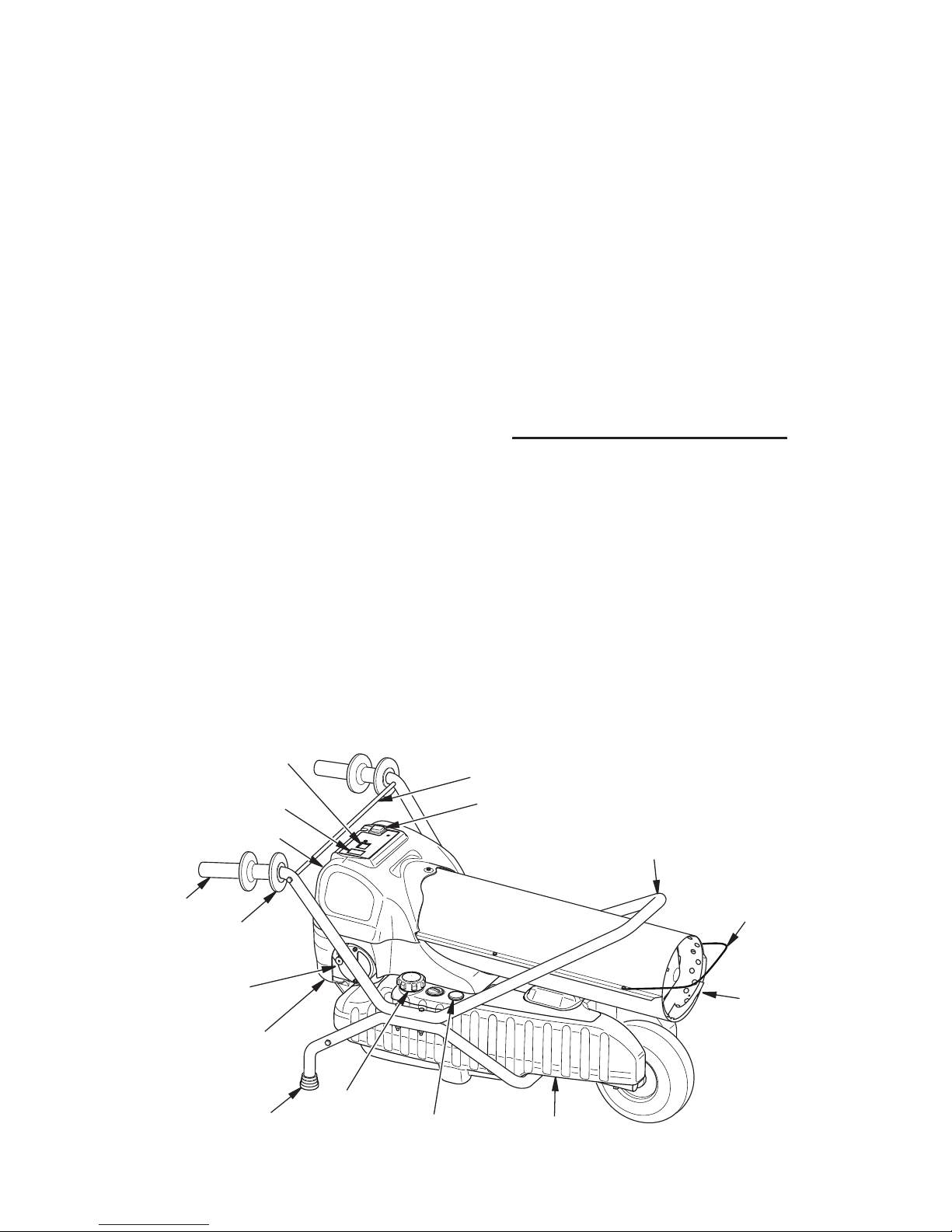
Hot Air
Outlet
Fuel Cap
Fuel Tank
ON/OFF Switch
Lower Shroud
Front
Handle
Figure 1 - 100, 150 and 200 Models
UNPACKING
Upper Shroud
Cold Air Inlet
Thermostat
Touch Pad
Fuel Gauge
1. Remove all packing items applied to
heater for shipment.
2. Remove all items from carton.
3. Check items for any shipping damage. If
heater is damaged call DESA Heating,
LLC at 1-866-672-6040 for replacement
parts before returning to dealer.
PRODUCT IDENTIFICATION
Wire Guard
(Canadian
models only,
see page 24)
Extension
Cord Wrap
Temperature
Display
Rubber Foot
Handle
Grip
Handle Crossbar

www.desatech.com
118419-01E4
SPECIFICATIONS
100 Models
• Output Rating: 100,000 Btu/Hr
• Fuel: Use only kerosene, #1/#2 diesel*/fuel oil, JET A or JP-8 fuels
• Fuel Tank Capacity: 13.5 gal (51.1 liters)
• Fuel Consumption per Hr: 0.75 gal (2.84 liters)
• Pump Pressure (psi): 5.9
• Electric Requirements: 120 V/60 HZ
• Amperage (Normal Run): 4.2
• Typical Motor Speed (RPM): 3315
• Motor Horsepower: 1/5
• Shipping Weight (Approx.): 71 lb (32.2 kg)
• Heater Weight without Fuel (Approx.): 60 lb (27.2 kg)
150 Models
• Output Rating: 150,000 Btu/Hr
• Fuel: Use only kerosene, #1/#2 diesel*/fuel oil, JET A or JP-8 fuels
• Fuel Tank Capacity: 13.5 gal (51.1 liters)
• Fuel Consumption per Hr: 1.13 gal (4.28 liters)
• Pump Pressure (psi): 6.4
• Electric Requirements: 120 V/60 HZ
• Amperage (Normal Run): 4.2
• Typical Motor Speed (RPM): 3300
• Motor Horsepower: 1/4
• Shipping Weight (Approx.): 71 lb (32.2 kg)
• Heater Weight without Fuel (Approx.): 60.5 b (27.4 kg)
200 Models
• Output Rating: 200,000 Btu/Hr
• Fuel: Use only kerosene, #1/#2 diesel*/fuel oil, JET A or JP-8 fuels
• Fuel Tank Capacity: 13.5 gal (51.1 liters)
• Fuel Consumption per Hr: 1.45 gal (5.49 liters)
• Pump Pressure (psi): 7.1
• Electric Requirements: 120 V/60 HZ
• Amperage (Normal Run): 4.2
• Typical Motor Speed (RPM): 3300
• Motor Horsepower: 1/4
• Shipping Weight (Approx.): 73 lb (33.1 kg)
• Heater Weight without Fuel (Approx.): 62.5 b (28.3 kg)
* Use of #2 diesel/fuel oil will result in noticeable odor and could require additional fuel lter
maintenance. Use in extreme cold temperatures may require nontoxic anti-icer additives.
www.desatech.com
118419-01E 5
ASSEMBLY
Estimated assembly time: 20 minutes
Tools Needed
• 5/16" nut driver or wrench
• 7/16" socket/ratchet or wrenches
• #4 Phillips screw driver
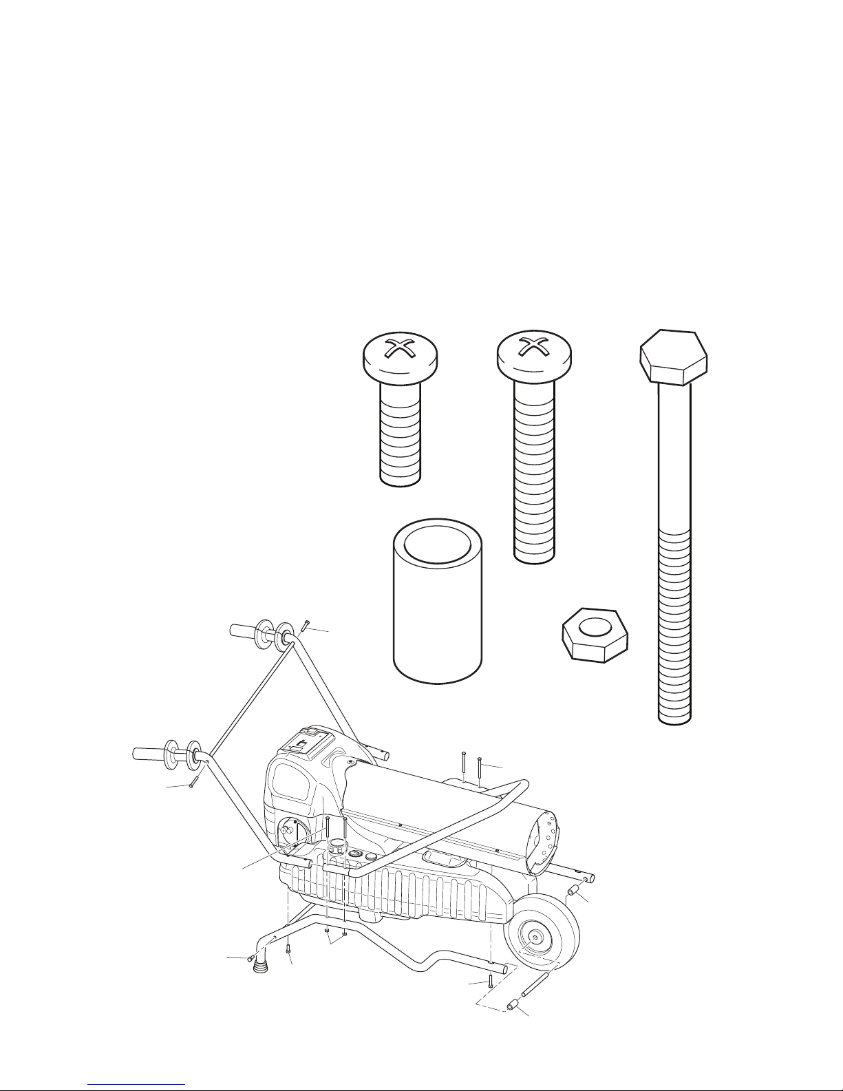
All models are furnished with a wheel, mounting hardware and handles. Parts will be found
in shipping carton.
You should have the following assembly parts:
Wheel (1), Axle (1), Handle Crossbar (1), Rear Cross Support (1), Legs (2), Rubber Feet (2), Rear
Handles (2), Front Handle (1), Handle Grips (2), Extension Cord Wraps (2) (see page 26).
Parts are referenced by designated letter throughout assembly instructions. Hardware packet
provided with heater may contain more parts than needed for heater assembly. Hardware
packet, part number 122094-01, contains the following (quantity used in parenthesis):
D
A
A
E
B
B
D
C
C
C
A
B
C
D
E
Description Part No.
A 5/16" - 18 x 7/8 PPH (4) 121123-03
B Spacer (2) 113497-02
C 5/16" - 18 x 1 1/2 PPH (4) 121123-04
D 1/4" - 20 x 2 3/4 Bolt (4) HC4-22C
E 1/4 - 20 Nut (4) NTC-4C
www.desatech.com
118419-01E6
ASSEMBLY
Continued
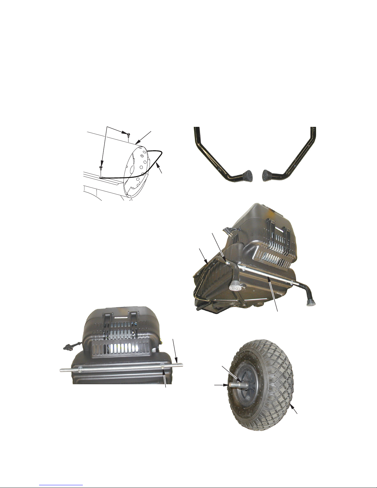
Figure 2 - Attaching Wire Guard
Wire Guard (Canadian Models)
1. Remove two screws securing front of upper shell to lower shell (see Figure 2).
2. Place wire guard on top of upper shell
ange.
3. Insert screws through wire guard and up-
per shell ange. Tighten screws rmly.
Wire
Guard
Upper Shell
Wire Guard Screws
(Canadian models only)
Rear
Cross
Support
Bolt (A)
Figure 3 - Attaching Rear Cross Support
Wheel and Handles
IMPORTANT: Install hardware nger tight only
at this time. After assembly is complete, use
tools to tighten entire assembly
1. Place heater with bottom of tank at on
oor.
2. Attach rear cross support with two bolts
(A), see Figure 3.
3. Push rubber feet onto each leg (left and
right), see Figure 4.
Figure 4 - Rubber Feet and Legs
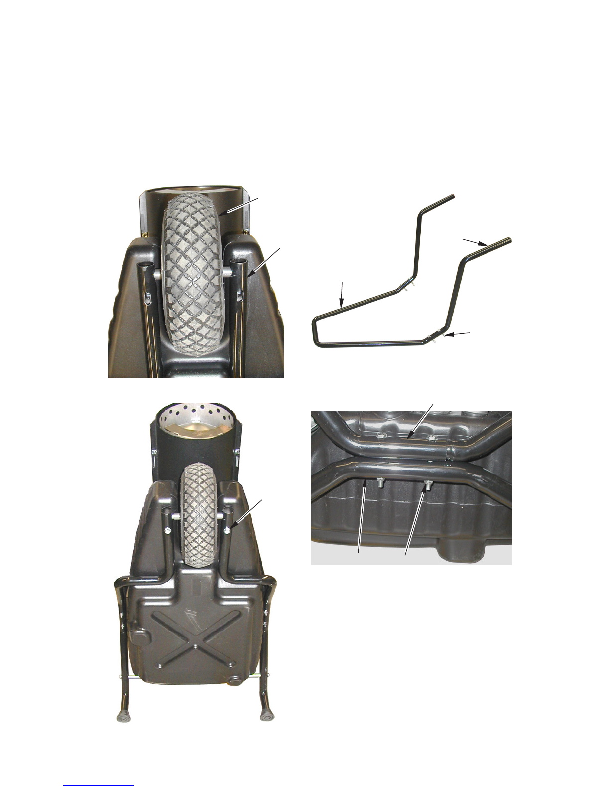
Figure 5 - Legs Attached to Rear Cross
Support
Bolt (A)
Rear Cross Support
Leg
Axle
Wheel
Figure 6 - Wheel and Axle
Spacer
(B)
4. Assemble each leg (left and right) onto
each side of rear cross support. Loosely
secure each side with bolts (A) (see Figure 5).
5. Lift front of heater so it is resting on back of
shroud and back of legs (see Figure 8).
6. Insert axle through wheel. Slide one
spacer (B) onto each end of wheel axle.
See Figure 6.
www.desatech.com
118419-01E 7
ASSEMBLY
Continued
7. Assemble wheel axle into front holes of
legs (see Figure 7).
8. Secure front legs to tank with two bolts
(C) (see Figure 8).
9. Tighten bolts from step 4 securing legs to
rear cross support.
10. Set heater down to oor on wheel and rear
legs.
Figure 7 - Installing Wheel and Axle
Wheel
Leg
Figure 8 - Attaching Legs to Tank
Bolt (C)
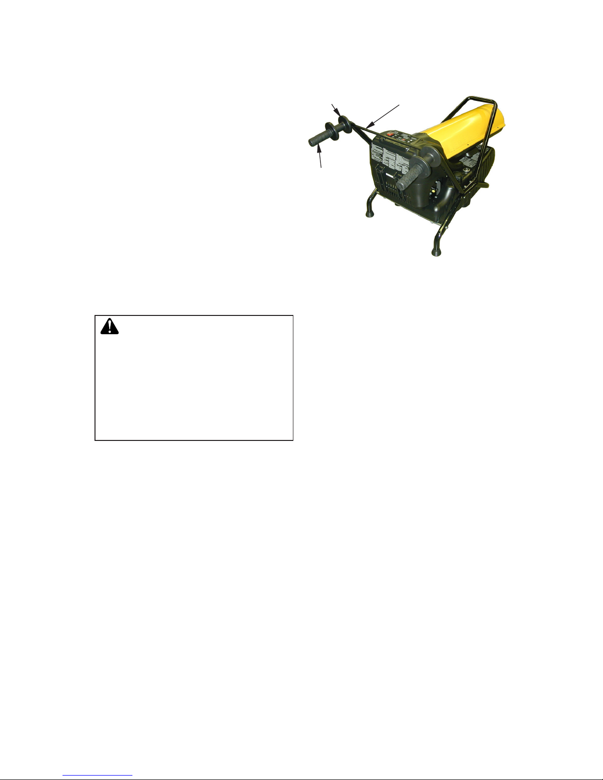
Figure 9 - Front and Rear Handle
Assembly
Front
Handle
Rear
Handle
Bolt (D)
Figure 10 - Handle and Leg Assembly
Leg
Handle Assembly
Nut (E)
11. Slide rear handle onto each end of front
handle. Insert bolts (D) into holes (2 per
side) (see Figure 9).
12. Lift handle assembly over heater. Align
and guide bolts into holes in leg.
13. Secure assembly with nuts (E) (see
Figure 10).
14. Tighten entire assembly with tools.
www.desatech.com
118419-01E8
FUELS
WARNING: Use only kerosene, #1/#2 diesel/fuel oil, JET
A or JP-8 fuels to avoid risk
of fire or explosion. Never
use gasoline, oil drained from
crankcases, naphtha, paint
thinners, alcohol or other highly
flammable fuels.
Use only kerosene, #1/#2 diesel*/fuel oil,
JET A, JP-8 fuels. Heavier fuels such as No.
2 fuel oil, No. 2 diesel fuel may also be used
but will result in:
• noticeable odor
• additional fuel lter maintenance
* Use of #2 diesel/fuel oil in extreme cold
temperatures may require nontoxic anti-icer
additives.
Do not use fuels heavier than No. 2 grade
or heavy oils such as oil drained from crankcases. These heavy oils will not ignite properly
and will contaminate the heater.
IMPORTANT: Use a KEROSENE ONLY (blue)
or DIESEL ONLY (yellow) storage container.
Be sure storage container is clean. Foreign
matter such as rust, dirt or water will cause the
ignition control assembly to shut down heater.
Foreign matter may also require heater's fuel
system to be frequently cleaned.
15. Assemble extension cord wrap to each
rear handle (see Figure 11).
16. Push handle grips onto handles (see
Figure 11).
17. Attach handle crossbar with 2 bolts (C)
ASSEMBLY
Continued
Figure 11 - Handle Grip and Cord Cleat
Assembly
Handle
Grip
Extension
Cord Wrap
Handle
Crossbar
www.desatech.com
118419-01E 9
VENTILATION
WARNING: Provide a fresh air
opening of at least three square
feet (2,800 square cm) for each
100,000 BTU/HR rating. Provide
extra fresh air if more heaters
are being used. The minimum
ventilation requirements must
be followed to avoid risks associated with carbon monoxide
poisoning. Make certain these
requirements are met prior to
operating heater.
Example: A 200,000 Btu/Hr (58.6 kw) heater
requires one of the following:
• a two-car garage door [16 feet (4.88 meter)
opening] raised 5" (12.7 cm)
• a single-car garage door [9 feet (2.74 meter) opening] raised 8" (20.3 cm)
• two, 30" (76.2 cm) windows raised 15"
(38.1 cm)
THEORY OF OPERATION
The Fuel System: The air pump forces air
through the air line. Air is then pushed through
the nozzle. This air causes fuel to be lifted
from the tank. A fine mist of fuel is sprayed
into the combustion chamber.
The Air System: The motor turns the fan. The
fan pushes air into and around the combustion
chamber. This air is heated and provides a
stream of clean, hot air.
The Ignition System: The high voltage ignitor provides power to the spark ignitor. This
ignites the fuel/air mixture in the combustion
chamber.
The Flame-Out Control System: This system causes the heater to shut down if the
flame goes out.
 Loading...