

Denon TU-604CI - Multi-Zone Dual AM/FM Tuner Owner's Manual
MULTIPLE TUNER
TU-604CI
Owner’s Manual
Bedienungsanleitung
English
• This owner’s manual is in English and German.
The content is identical in both language versions.
• The manual explains which bands (tuner types) are
non-compatible by region of use. For the regions
where reception is possible, refer to the title of each
explanation item.
Deutsch
• Diese Bedienungsanleitung ist auf Englisch und
Deutsch.
Der Inhalt ist in beiden Sprachen derselbe.
• In der Anleitung wird erläutert, welche
Frequenzbänder (Tunerausführungen)
regionsabhängig nicht kompatibel sind. Für die
Regionen, in denen der Empfang möglich ist, sind
Erläuterungen unter den jeweiligen Titeln enthalten.
ENGLISH DEUTSCH
CAUTION
RISK OF ELECTRIC SHOCK
DO NOT OPEN
SAFETY PRECAUTIONS
n
CAUTION:
TO REDUCE THE RISK OF ELECTRIC SHOCK, DO NOT REMOVE
COVER (OR BACK). NO USER-SERVICEABLE PARTS INSIDE.
REFER SERVICING TO QUALIFIED SERVICE PERSONNEL.
The lightning flash with arrowhead symbol, within an equilateral
triangle, is intended to alert the user to the presence of
uninsulated “dangerous voltage” within the product’s enclosure
that may be of sufficient magnitude to constitute a risk of electric
shock to persons.
The exclamation point within an equilateral triangle is intended
to alert the user to the presence of important operating
and maintenance (servicing) instructions in the literature
accompanying the appliance.
WARNING:
TO REDUCE THE RISK OF FIRE OR ELECTRIC SHOCK, DO NOT
EXPOSE THIS APPLIANCE TO RAIN OR MOISTURE.
CAUTION:
• The ventilation should not be impeded by covering the ventilation
openings with items, such as newspapers, tablecloths, curtains,
etc.
• No naked flame sources, such as lighted candles, should be
placed on the unit.
• Observe and follow local regulations regarding battery disposal.
• Do not expose the unit to dripping or splashing fluids.
• Do not place objects filled with liquids, such as vases, on the
unit.
ACHTUNG:
• Die Belüftung sollte auf keinen Fall durch das Abdecken der
Belüftungsöffnungen durch Gegenstände wie beispielsweise
Zeitungen, Tischtücher, Vorhänge o. Ä. behindert werden.
• Auf dem Gerät sollten keinerlei direkte Feuerquellen wie
beispielsweise angezündete Kerzen aufgestellt werden.
• Bitte beachten Sie bei der Entsorgung der Batterien die örtlich
geltenden Umweltbestimmungen.
• Das Gerät sollte keiner tropfenden oder spritzenden Flüssigkeit
ausgesetzt werden.
• Auf dem Gerät sollten keine mit Flüssigkeit gefüllten Behälter
wie beispielsweise Vasen aufgestellt werden.
IMPOTANT SAFETY
INSTRUCTIONS
1. Read these instructions.
2. Keep these instructions.
3. Heed all warnings.
4. Follow all instructions.
5. Do not use this apparatus near water.
6. Clean only with dry cloth.
7. Do not block any ventilation openings.
Install in accordance with the manufacturer's instructions.
8. Do not install near any heat sources such as radiators, heat registers,
stoves, or other apparatus (including amplifiers) that produce heat.
9. Do not defeat the safety purpose of the polarized or grounding-type plug. A
polarized plug has two blades with one wider than the other. A grounding
type plug has two blades and a third grounding prong. The wide blade or the
third prong are provided for your safety. If the provided plug does not fit into
your outlet, consult an electrician for replacement of the obsolete outlet.
10. Protect the power cord from being walked on or pinched particularly at
plugs, convenience receptacles, and the point where they exit from the
apparatus.
11. Only use attachments/accessories specified by the manufacturer.
12. Use only with the cart, stand, tripod, bracket, or table
specified by the manufacturer, or sold with the apparatus.
When a cart is used, use caution when moving the cart/
apparatus combination to avoid injury from tip-over.
13. Unplug this apparatus during lightning storms or when
unused for long periods of time.
14. Refer all servicing to qualified service personnel.
Servicing is required when the apparatus has been damaged in any way,
such as power-supply cord or plug is damaged, liquid has been spilled or
objects have fallen into the apparatus, the apparatus has been exposed to
rain or moisture, does not operate normally, or has been dropped.
15. Batteries shall not be exposed to excessive heat such as sunshine, fire or
the like.
CAUTION:
To completely disconnect this product from the mains, disconnect
the plug from the wall socket outlet.
The mains plug is used to completely interrupt the power supply to
the unit and must be within easy access by the user.
VORSICHT:
Um dieses Gerät vollständig von der Stromversorgung abzutrennen,
ziehen Sie bitte den Stecker aus der Wandsteckdose.
Der Netzstecker wird verwendet, um die Stromversorgung zum
Gerät völlig zu unterbrechen; er muss für den Benutzer gut und
einfach zu erreichen sein.
FCC INFORMATION (For US customers)
1. COMPLIANCE INFORMATION
Product Name: Multi
Model Number:
This product complies with Part 15 of the FCC Rules. Operation is subject
to the following two conditions: (1) this product may not cause harmful
interference, and (2) this product must accept any interference received,
including interference that may cause undesired operation.
Denon Electronics (USA), LLC
(a D & M Holdings Company)
100 Corporate Drive
Mahwah, NJ 07430-2041
Tel. (800) 497-8921
2. IMPORTANT NOTICE: DO NOT MODIFY THIS PRODUCT
This product, when installed as indicated in the instructions contained
in this manual, meets FCC requirements. Modification not expressly
approved by DENON may void your authority, granted by the FCC, to use
the product.
3. NOTE
This product has been tested and found to comply with the limits for
a Class B digital device, pursuant to Part 15 of the FCC Rules. These
limits are designed to provide reasonable protection against harmful
interference in a residential installation.
This product generates, uses and can radiate radio frequency energy and,
if not installed and used in accordance with the instructions, may cause
harmful interference to radio communications. However, there is no
guarantee that interference will not occur in a particular installation. If this
product does cause harmful interference to radio or television reception,
which can be determined by turning the product OFF and ON, the user
is encouraged to try to correct the interference by one or more of the
following measures:
• Reorient or relocate the receiving antenna.
• Increase the separation between the equipment and receiver.
• Connect the product into an outlet on a circuit different from that to
which the receiver is connected.
• Consult the local retailer authorized to distribute this type of product or
an experienced radio/TV technician for help.
This Class B digital apparatus complies with Canadian ICES-003.
Cet appareil numérique de la classe B est conforme à la norme NMB-003 du
Canada.
ple Tuner
TU-604CI
I

ENGLISH
ENGLISHDEUTSCH
NOTE ON USE / HINWEISE ZUM GEBRAUCH
n
• Keep the unit free from moisture, water,
and dust.
• Halten Sie das Gerät von Feuchtigkeit,
• Avoid high temperatures.
Allow for sufficient heat dispersion when
installed in a rack.
• Vermeiden Sie hohe Temperaturen.
Beachten Sie, dass eine ausreichende
Belüftung gewährleistet wird, wenn das
Gerät auf ein Regal gestellt wird.
• Handle the power cord carefully.
Hold the plug when unplugging the cord.
• Gehen Sie vorsichtig mit dem Netzkabel
um.
Halten Sie das Kabel am Stecker, wenn Sie
den Stecker herausziehen.
Wasser und Staub fern.
• Unplug the power cord when not using the
unit for long periods of time.
• Wenn das Gerät längere Zeit nicht
verwendet werden soll, trennen Sie das
Netzkabel vom Netzstecker.
* (For apparatuses with ventilation holes)
• Do not obstruct the ventilation holes.
• Decken Sie den Lüftungsbereich nicht ab.
• Do not let foreign objects into the unit.
• Lassen Sie keine fremden Gegenstände in
das Gerät kommen.
• Do not let insecticides, benzene, and
thinner come in contact with the unit.
• Lassen Sie das Gerät nicht mit Insektiziden,
Benzin oder Verdünnungsmitteln in
Berührung kommen.
• Never disassemble or modify the unit in
any way.
• Ne jamais démonter ou modifier l’appareil
d’une manière ou d’une autre.
For Europe model
n
DECLARATION OF CONFORMITY
We declare under our sole responsibility that this product, to which this declaration relates, is in
conformity with the following standards:
EN60065, EN55013, EN55020, EN61000-3-2 and EN61000-3-3.
Following the provisions of 2006/95/EC and 2004/108/EC Directive.
ÜBEREINSTIMMUNGSERKLÄRUNG
Wir erklären unter unserer Verantwortung, daß dieses Produkt, auf das sich diese Erklärung bezieht,
den folgenden Standards entspricht:
EN60065, EN55013, EN55020, EN61000-3-2 und EN61000-3-3.
Entspricht den Verordnungen der Direktive 2006/95/EC und 2004/108/EC.
DENON Europe
Division of D&M Germany GmbH
An der Landwehr 19, Nettetal,
D-41334 Germany
A NOTE ABOUT RECYCLING:
This product’s packaging materials are recyclable and can be reused. Please dispose of any materials
in accordance with the local recycling regulations.
When discarding the unit, comply with local rules or regulations.
Batteries should never be thrown away or incinerated but disposed of in accordance with the local
regulations concerning battery disposal.
This product and the supplied accessories, excluding the batteries, constitute the applicable product
according to the WEEE directive.
HINWEIS ZUM RECYCLING:
Das Verpackungsmaterial dieses Produktes ist zum Recyceln geeignet und kann wieder verwendet
werden. Bitte entsorgen Sie alle Materialien entsprechend der örtlichen Recycling-Vorschriften.
Beachten Sie bei der Entsorgung des Gerätes die örtlichen Vorschriften und Bestimmungen.
Die Batterien dürfen nicht in den Hausmüll geworfen oder verbrannt werden; bitte entsorgen Sie die
Batterien gemäß der örtlichen Vorschriften.
Dieses Produkt und das im Lieferumfang enthaltene Zubehör (mit Ausnahme der Batterien!)
entsprechen der WEEE-Direktive.
II

ENGLISH
Contents
Getting Started
Accessories ·····················································································2
Cautions on Handling ····································································· 2
Cautions on Installation ·································································2
About the Remote Control Unit ····················································3
Inserting the Batteries ···································································3
Operating Range of the Remote Control Unit ································3
Part Names and Functions ····························································4
Front Panel ·····················································································4
Display ···························································································4
Rear Panel ······················································································5
Remote Control Unit ······································································6
Connections
Preparations ····················································································7
Cables Used for Connections ························································7
Connecting the Amplifier (Except SIRIUS) ····································7
Connecting the Antenna Terminals ··············································8
FM/AM ···························································································8
HD Radio ························································································8
XM ·································································································9
DAB ································································································9
SIRIUS ·························································································· 10
SIRIUS Connector ········································································10
Connecting the Network ····························································· 11
Connecting the External Controller ············································12
Connecting the Power Cord ························································12
Once Connections are Completed ··············································12
Setup
Example of Display of Default Values ········································13
Operations ····················································································· 13
Entering characters ······································································13
Menu Map ·····················································································14
Main setup ····················································································15
a Auto Preset ·············································································15
s Preset Skip ··············································································15
d Preset Name ···········································································16
f Rename···················································································16
g Antenna Aiming ······································································16
h Auto Tune ···············································································16
j Tuning Aid ···············································································16
k DRC Value ···············································································17
l DAB Initialize ···········································································17
A0 Parental Lock ···········································································17
Network Setup ·············································································17
a Network Information ······························································· 17
s Network Setup ········································································18
Option Setup ················································································· 19
a Dimmer ···················································································19
s Remote ID Setup ····································································19
d Setup Lock ··············································································19
f Ether Power ············································································19
g RS-232C Power·······································································19
h Maintenance ···········································································20
j Firmware Update ····································································20
Status ····························································································20
Check the Status of Each Unit ·····················································20
Operations
Preparations ··················································································21
Turning TU-604CI power on ·························································21
Turning on the power of each tuner unit ·····································21
Selecting each tuner unit ·····························································21
Switching the brightness of the display ·······································21
Listening to FM/AM Broadcasts ·················································22
Basic Operation ············································································22
Presetting Radio Stations (Preset Memory) ·································22
Listening to Preset Stations ·························································22
About RDS (Radio Data System) ··················································23
RDS Search ··················································································24
PTY Search ···················································································24
TP Search ·····················································································24
RT (Radio Text) ·············································································24
Direct Frequency Tuning ······························································25
Listening to XM Satellite Radio Programs ································· 26
Basic Operation (Channel Search) ················································26
Direct Channel Search ·································································27
Category Search ···········································································27
Checking the XM Signal Strength and Radio ID ···························27
Listening to SIRIUS Satellite Radio Programs ··························· 28
Basic Oparation (Channel Search) ················································28
Direct Channel Search ··································································28
Category Search ···········································································29
Parental Lock ················································································29
Checking the SIRIUS Signal Strength and Radio ID ·····················29
Listening to HD Radio™ Stations ···············································30
Basic Operation ············································································30
Selecting the Audio Programs ·····················································31
Direct Frequency Tuning ······························································31
Check the HD Radio Reception Information ································32
Listening to DAB Broadcasts ················································· 32, 33
Basic Operation ············································································33
Selecting the Station Order ··························································34
Check the DAB Reception Information ········································34
Operating the TU-604CI Using a Browser (Web Control) ···34, 35
Convenient Functions
Last Function Memory ································································· 36
Backup Memory ············································································ 36
Resetting the Microprocessor ·····················································36
Remote Control Unit Operations ···············································37
Setting the Remote ID ·································································38
Resetting the Settings ·································································38
Troubleshooting ···································································· 39, 40
Specifications ··············································································· 41
Getting Started
t
y
i
o
(For America model)
r t
(For European model)
Thank you for purchasing this DENON product. To ensure proper
operation, please read this owner’s manual carefully before using the
product.
After reading them, be sure to keep them for future reference.
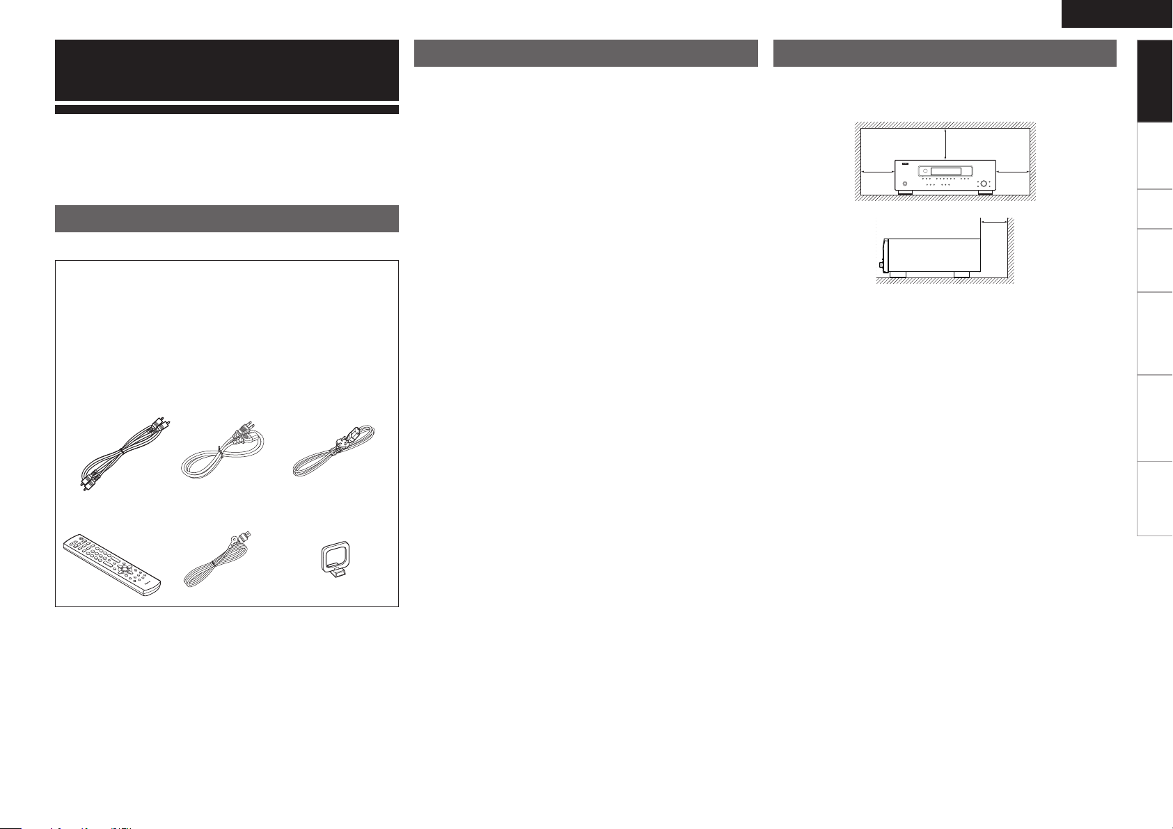
Accessories
Check that the following parts are supplied with the product.
q Owner’s manual ......................................................................1
w Warranty (for North America model only) ................................ 1
e Service station list ...................................................................1
r Audio cable .............................................................................. 2
t Power cord (Cord length: Approx. 5.9 ft / 1.8 m) .................... 1
y Remote control (RC-1093) .......................................................1
u R03/AAA batteries ...................................................................2
i FM indoor antenna ..................................................................2
o AM loop antenna .....................................................................2
Cautions on Handling Cautions on Installation
• Before turning the ON/STANDBY switch on
Check once again that all connections are correct and that there are
no problems with the connection cables.
•
Power is supplied to some of the circuitry even when the unit is
set to the standby mode. When traveling or leaving home for long
periods of time, be sure to unplug the power cord from the power
outlet.
• About condensation
If there is a major difference in temperature between the inside of
the unit and the surroundings, condensation (dew) may form on
the operating parts inside the unit, causing the unit not to operate
properly.
If this happens, let the unit sit for an hour or two with the power
turned off and wait until there is little difference in temperature
before using the unit.
• Cautions on using mobile phones
Using a mobile phone near this unit may result in noise. If so, move
the mobile phone away from this unit when it is in use.
• Moving the unit
Turn off the power and unplug the power cord from the power
outlet.
Next, disconnect the connection cables to other system units before
moving the unit.
•
Note that the illustrations in these instructions may differ from the
actual unit for explanation purposes.
Note:
For proper heat dispersal, do not install this unit in a confined
space, such as a bookcase or similar enclosure.
b Note
b
ENGLISH
Getting Started Connections Setup Operations Remote Control Troubleshooting
b
b
Wall
(For North America
model)
Specifications
(For Europe model)

ENGLISH
Getting Started Connections Setup Operations Remote Control Troubleshooting Specifications
About the Remote Control Unit
Inserting the Batteries
q Lift the clasp and remove the
rear lid.
Operating Range of the Remote Control
Unit
Point the remote control unit at the remote sensor when operating it.
w Load the two batteries properly
as indicated by the marks in
the battery compartment.
R03/AAA
30°
30°
e Put the rear cover back on.
NOTE
• Replace the batteries with new ones if the set does not operate
even when the remote control unit is operated close to the unit.
• The supplied batteries are only for verifying operation.
• When inserting the batteries, be sure to do so in the proper direction,
following the “q” and “w” marks in the battery compartment.
• To prevent damage or leakage of battery fluid:
• Do not use a new battery together with an old one.
• Do not use two different types of batteries.
• Do not attempt to charge dry batteries.
• Do not short-circuit, disassemble, heat or dispose of batteries in
flames.
• If the battery fluid should leak, carefully wipe the fluid off the inside
of the battery compartment and insert new batteries.
• Remove the batteries from the remote control unit if it will not be in
use for long periods.
• When replacing the batteries, have the new batteries ready and
insert them as quickly as possible.
Approx. 23 feet / 7 m
NOTE
The set may function improperly or the remote control unit may not
operate if the remote control sensor is exposed to direct sunlight,
strong artificial light from an inverter type fluorescent lamp or infrared
light.
q
Q0o
W0 Q9 Q8
Q1
ew
Q2 Q3 Q4 Q5 Q6 Q7
rt y ui
w
q e
Part Names and Functions
For buttons not explained here, see the page indicated in parentheses ( ).
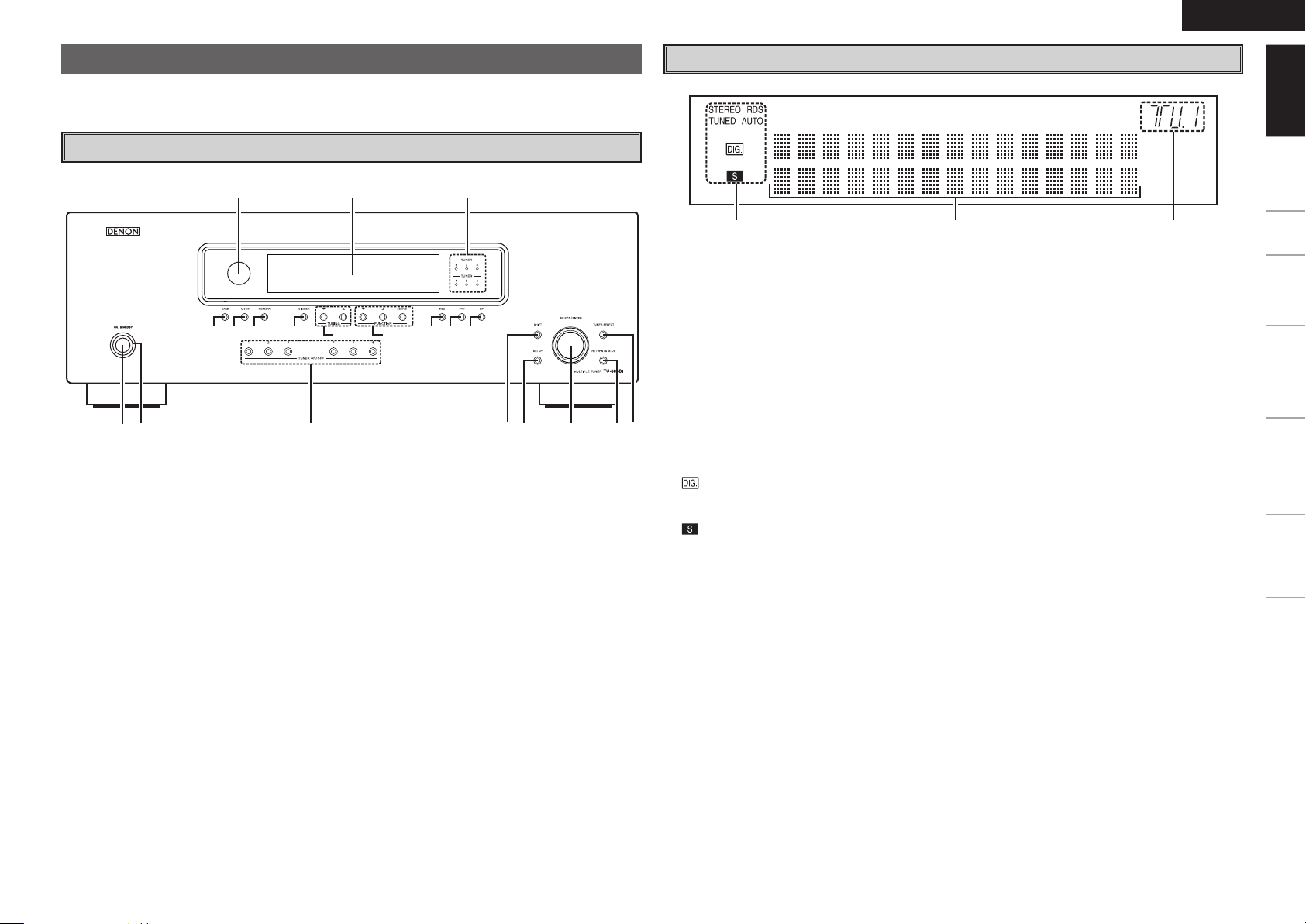
Front Panel
ENGLISH
Getting Started Connections Setup Operations Remote Control Troubleshooting
Display
q Power operation button
(ON/STANDBY) ··········································(21)
w Power indicator ··········································(21)
e TUNER ON/OFF buttons (1 ~ 6) ················ (21)
r SHIFT button ··············································· (13)
t SETUP button ············································· (13)
y SELECT/ENTER knob ································· (13)
u RETURN/STATUS button ·························· (13)
i TUNER SELECT button ······························(21)
o BAND button ·············································· (22)
Q0 MODE button ·············································· (22)
Q1 MEMORY button ········································(22)
Q2 DIMMER button ·········································· (19)
Q3 TUNING buttons (d f) ·······························(22)
Q4 FUNCTION buttons (d f, SEARCH) ···· (15, 25)
Q5 RDS button ················································· (24)
Q6 PTY button ··················································(24)
Q7 RT button ····················································(24)
Q8 TUNER ON/OFF indicators
(TUNER 1 ~ 6) ·············································· (21)
Q9 Display
W0 Remote control sensor ································ (3)
q Tuner reception mode indicators
These light according to the reception conditions
when the tuner select is set to “TUNER”, “HD
Radio” or “DAB”.
• STEREO
In the FM mode, this light when receiving analog
stereo broadcasts.
• TUNED
This light when the broadcast is properly tuned
in.
• RDS
This light when receiving RDS broadcasts.
• AUTO
This light when in the auto tuning mode.
•
This light when an HD Radio station tuned in (for
North America model only).
•
This light when the Secondary service
Component in DAB is received (for Europe
model only).
w Information display
e Tuner select indicator
Displays the selected channel tuner unit number.
eg, if TUNER-1 is selected, “TU.1” is displayed.
Specifications
t
e
q
yuQ7 Q6ioQ0Q1Q2Q3Q4Q5
r e r e r e r e r e rw
ENGLISH
Getting Started Connections Setup Operations Remote Control Troubleshooting Specifications
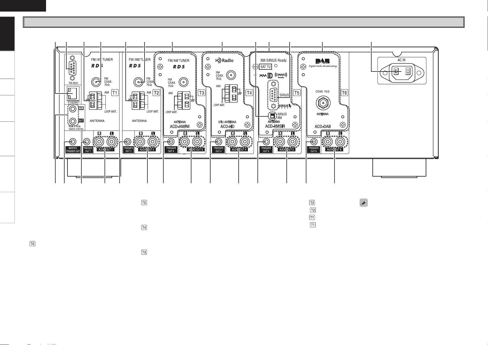
Rear Panel
q REMOTE CONTROL jacks ·························· (12)
w MASTER TRIGGER OUT jack ····················· (12)
e TRIGGER OUT jacks (1 ~ 6) ························ (12)
r Analog audio output connectors
(AUDIO OUT 1 ~ 6) ·······································(7)
t AC inlet (AC IN) ··········································· (12)
y TUNER-6 slot (for inserting an option unit)
Showing DAB unit (option board : ACD-DAB,
for Europe model only) installed as an example
u TUNER-5 slot (for inserting an option unit)
Showing XM / SIR TUNER unit (option board :
ACD-XMSIR, for North America model only)
installed as an example
i TUNER-4 slot (for inserting an option unit)
Showing HD Radio unit (option board :
ACD-HD, for North America model only)
installed as an example
o TUNER-3 slot (for inserting an option unit)
Showing FM/AM TUNER unit (option board :
ACD-AMFM) installed as an example
Q0 FM antenna terminal for (TUNER-2) ·····(8)
Q1 AM antenna terminal for (TUNER-2) ····· (8)
Q2 FM antenna terminal for (TUNER-1) ·····(8)
Q3 AM antenna terminal for (TUNER-1) ····· (8)
Q4 RS-232C connector ····································· (12)
Q5 ETHERNET connector ·································(11)
Q6 SIRIUS connector ······································· (10)
Q7 SIRIUS/XM select switch······················· (9, 10)
After operating this switch, turn the power back
on.
(In this figure, an option board is fitted.)
For details on how to install an option board, refer to
the installation manual for the board.

q
y
i
o
Q1
Q2
Q0
u
e
t
r
w
Q7
W3
W1
W2
W0
Q8
Q5
Q9
Q6
Q4
W4
W5
Q3
Remote Control Unit
q Tuner select indicators ······························ (21)
w Advanced setup button ·····························(38)
e Tuner unit power off button (OFF) ···········(21)
r REMOTE ID button ·····································(38)
t RDS button ················································· (24)
y Number buttons ·········································(22)
u SEARCH button (SRCH) ·····························(25)
i CHANNEL buttons (+, –) ···························· (13)
o BAND button ·············································· (22)
Q0 DIMMER button ·········································· (19)
Q1 Cursor buttons (uio p) ························· (13)
Q2 SETUP button ············································· (13)
Q3 Preset station buttons (A ~ G) ··················(22)
Q4 Remote control signal transmitter ·············(3)
Q5 TUNER SELECT button ······························(21)
Q6 Power operation buttons
(ALL OFF, ALL ON) ·····································(21)
Q7 Tuner unit power on button (ON) ············· (21)
Q8 RT button ····················································(24)
Q9 PTY button ··················································(24)
W0 TUNING buttons (df) ································(22)
W1 MODE button ·············································· (22)
W2 STATUS button ·········································· (20)
W3 ENTER button ············································· (13)
W4 RETURN button ·········································· (13)
W5 MEMORY button ········································ (22)
NOTE
The PROGRESSIVE button cannot be used.
ENGLISH
Getting Started Connections Setup Operations Remote Control Troubleshooting
Specifications
"6%*0
"6%*0
-3
*/
"6%*0
"6%*0
-3
*/
"6%*0
"6%*0
-3
*/
"6%*0
"6%*0
-3
*/
"6%*0
"6%*0
-3
*/
"6%*0
"6%*0
-3
*/
R
L
R
L
R
L
R
L
R
L
R
L
R
L
R
L
R
L
R
L
R
L
R
L
R
L
R
L
ENGLISH
Getting Started Connections Setup Operations Remote Control Troubleshooting Specifications
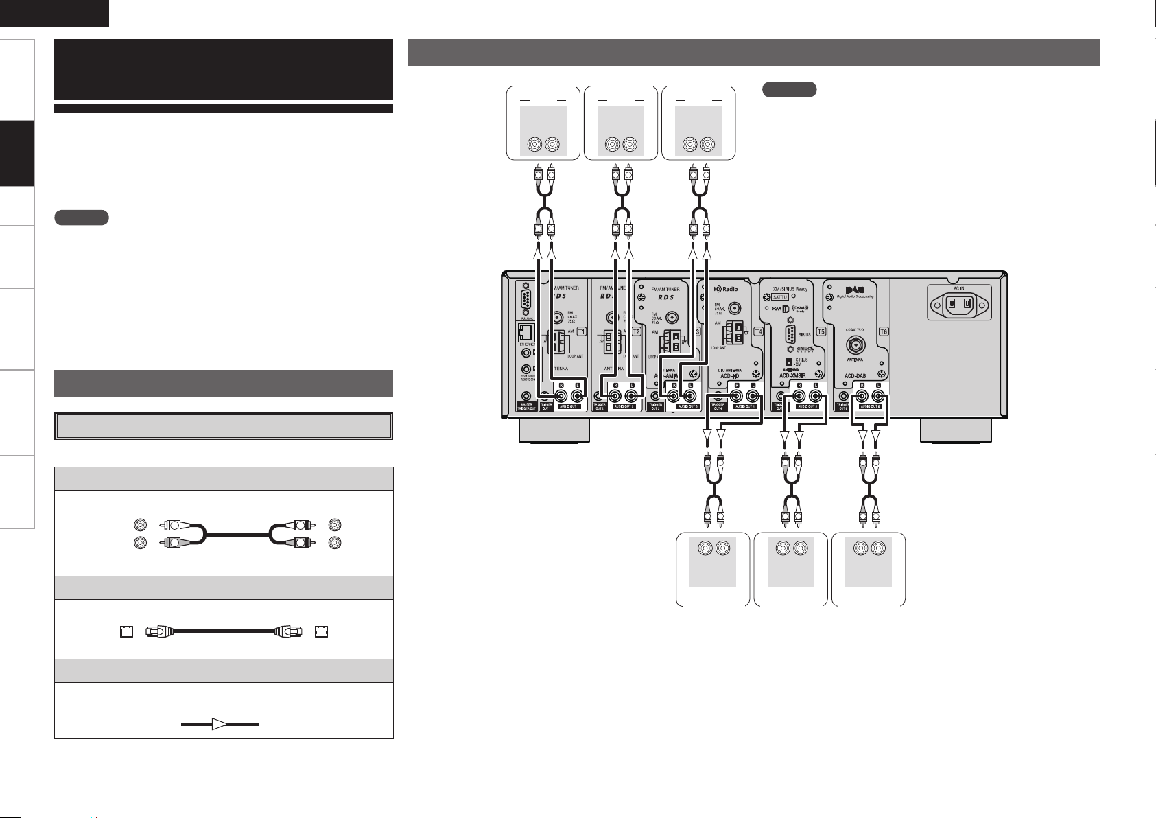
Connecting the Amplifier (Except SIRIUS)
Connections
Connections for all compatible are described in this owner’s
manual. Please select the types of connections suited for the
equipment you are connecting.
With some types of connections, certain settings must be made
on the TU-604CI. For details, refer to the instructions for the
respective connection items below.
NOTE
• Do not plug in the power cord until all connections have been
completed.
• When making connections, also refer to the operating instructions of
the other components.
• Be sure to connect the left and right channels properly (left with left,
right with right).
• Do not bundle power cords together with connection cables. Doing
so can result in humming or noise.
Preparations
Cables Used for Connections
Select the cables according to the equipment being connected.
Audio cables
Amplifier 1 Amplifier 2 Amplifier 3
NOTE
See page 10 for information on how to connect SIRIUS.
Analog connections (stereo)
(White)
(Red)
Network connections
Audio signal:
Output
Stereo pin-plug cable
Other cable
Ethernet cable
Signal direction
Input
Amplifier 4 Amplifier 5 Amplifier 6
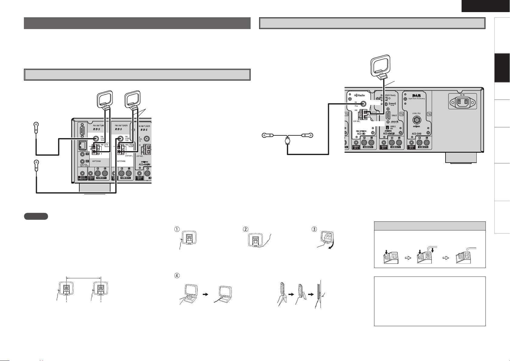
Connecting the Antenna Terminals
The following explains how to connect the included antenna only.
When supplying multiple input from a single outdoor antenna, be sure to use a splitter that is compatible
with the specifications of the tuner and its installation environment.
Refer to the owner’s manual for each item of equipment regarding connection of an outdoor antenna and
splitter.
HD Radio
HD Radio is a service that is only available within the United States.
AM loop antenna (large, for HD Radio broadcasting, supplied)
(Option board : ACD-HD (sold separately), for North America model only)
ENGLISH
Getting Started Connections Setup Operations Remote Control Troubleshooting
FM/AM
FM indoor
antenna
(supplied)
NOTE
• Do not connect two FM antennas simultaneously.
• Even if an external AM antenna is used, do not
disconnect the AM loop antenna.
• Make sure the AM loop antenna lead terminals do
not touch metal parts of the panel.
• Locate each AM loop antenna at a distance that does
not cause interference (1.7 ft / 50 cm or more). (FM/
AM, HD Radio)
1.7 ft / 50 cm or more
AM loop antenna
(small, supplied)
Twist pair cable (Black)
n AM loop antenna assembly
Remove the vinyl tie and take
out the connection line.
a. With the antenna on top of
any stable surface.
Mount
FM indoor antenna
(dipole, for HD Radio
broadcasting, supplied)
Connect to the AM
antenna terminals.
Bend in the reverse direction.
b. With the antenna attached
to a wall.
Installation hole Mount on wall, etc.
Shield cable (Gray)
Black
White
Connection of AM loop antennas
1. Push the
lever.
Note to CATV system installer:
This reminder is provided to call the CATV system
installer’s attention to Article 820-40 of the NEC
which provides guidelines for proper grounding
and, in particular, specifies that the cable ground
shall be connected to the grounding system of
the building, as close to the point of cable entry
as practical.
2. Insert the
conductor.
3. Return the
lever.
Specifications
ENGLISH
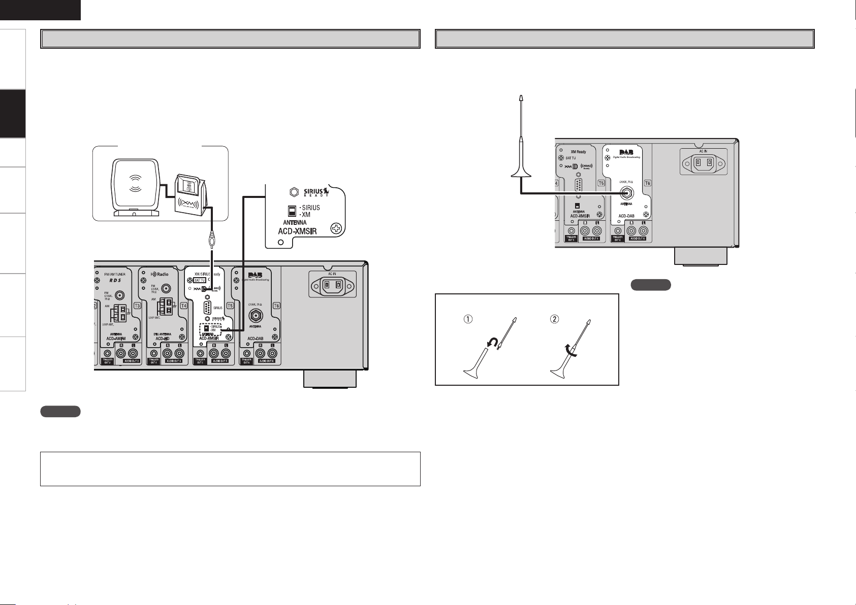
XM
Getting Started Connections Setup Operations Remote Control Troubleshooting
• The TU-604CI is an XM Ready
• Plug the XM Mini-Tuner and Home Dock into the XM connector on the rear panel.
• Position the Home Dock antenna near a south-facing window to receive the best signal.
For details, see “Listening to XM Satellite Radio Programs” (vpage 26).
When making connections, also refer to the operating instructions of the XM Mini-Tuner and Home
(Option board : ACD-XMSIR (sold separately), for North America model only)
XM
®
tuner. You can receive XM® Satellite Radio by connecting to the XM Mini-
Tuner and Home Dock (includes home antenna, sold separately) and subscribing to the XM service.
Dock.
(Option board : ACD-DAB (sold separately), for Europe model only)
DAB
n Installing the DAB indoor antenna
q For details, see “Listening to DAB Broadcasts” (vpage 32).
w Use “Tuning Aid” to set position at which reception sensitivity is optimum (vpage 16).
XM Mini-Tuner and
Home Dock
Flick the switch
down
Specifications
NOTE
Keep the power cord unplugged until the XM Mini-Tuner and Home Dock connection have been
completed.
DAB indoor antenna
(supplied)
n DAB indoor antenna assembly
Mount the antenna’s screw to the stand.
NOTE
There is a magnetic on the bottom surface of the
DAB indoor antenna. Keep it away from monitors,
etc.
• The XM name and related logo are registered trademarks of XM Satellite Radio Inc. All rights
reserved.
• XM Ready is a registered trademark of XM Satellite Radio Inc. All rights reserved.
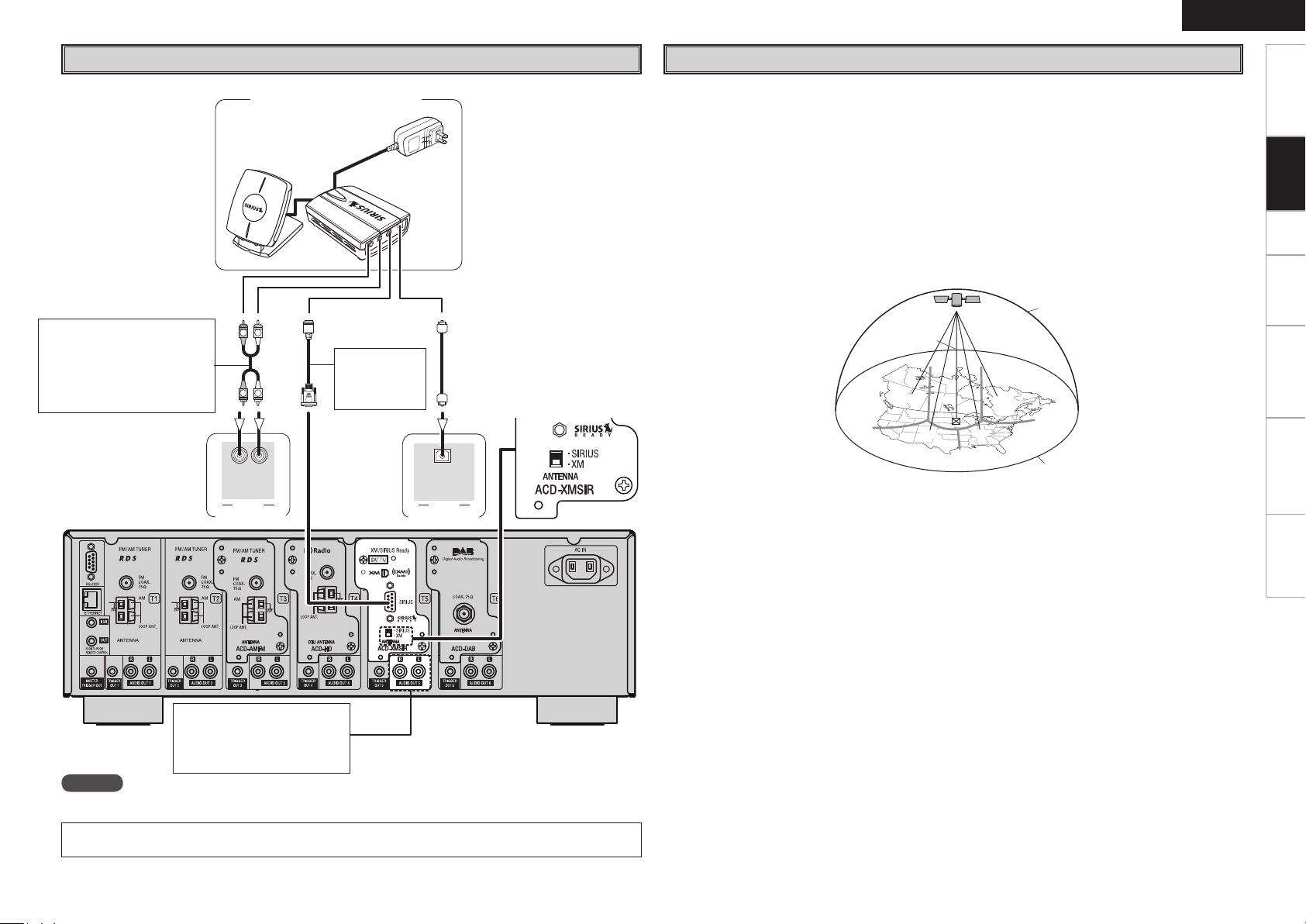
SIRIUS
R
L
R
L
"6%*0
"6%*0
-3
*/
"6%*0
015*$"-
*/
q
w
e
r
t
SOUTH
NORTH
WEST
SKY
EAST
HORIZON
(Option board : ACD-XMSIR (sold separately), for North America model only)
ENGLISH
Getting Started Setup Operations Remote Control Troubleshooting
SIRIUS Connector
Input the SiriusConnect
Home Tuner’s audio output
to an audio input terminal
not used by amplifier when
connecting digital audio.
SiriusConnect Home Tuner
Amplifier
Use a reverse
adapter as
required.
Amplifier
Flick the switch up
• The TU-604CI is a SIRIUS Satellite Radio Ready® receiver. You can receive SIRIUS® Satellite Radio by
connecting to the SiriusConnect Home Tuner and subscribing to the SIRIUS service.
• Connect the SiriusConnect Home Tuner to the 232C terminal and the audio terminal on the rear panel. To
make the connection, use the 232C cable in the accompanying Prokit.
• Position the Home Tuner antenna near a south-facing window to receive the best signal.
For details, see “Listening to SIRIUS Satellite Radio Programs” (vpage 28).
When making connections, also refer to the operating instructions of the SiriusConnect Home Tuner.
n Positioning the Antenna
For a consistent satellite signal, the antenna must be positioned correctly. Use the following map to
determine which area you are in and position the antenna accordingly.
Area 1 : Point the antenna toward the sky in the east, northeast, or southeast, either through a window
or outside.
Area 2 : Point the antenna toward the sky in the north or northeast, either through a window or outside.
Area 3 : Point the antenna toward the sky in the north or northwest, either through a window or
outside.
Area 4 : Point the antenna toward the sky in the west, northwest, or southwest, either through a window
or outside.
Area 5 : Put the antenna outside and point it straight up. The antenna cannot be used indoors.
Connections
Specifications
No SIRIUS Satellite Radio
signal output from the
AUDIO OUT 5 terminal.
NOTE
Keep the power cord unplugged until the SiriusConnect Home Tuner connection have been completed.
©2006 SIRIUS Satellite Radio Inc. “SIRIUS”, the SIRIUS dog logo, and channel names and logos are
trademarks of SIRIUS Satellite Radio Inc.
0
ENGLISH
Getting Started Setup Operations Remote Control Troubleshooting Specifications
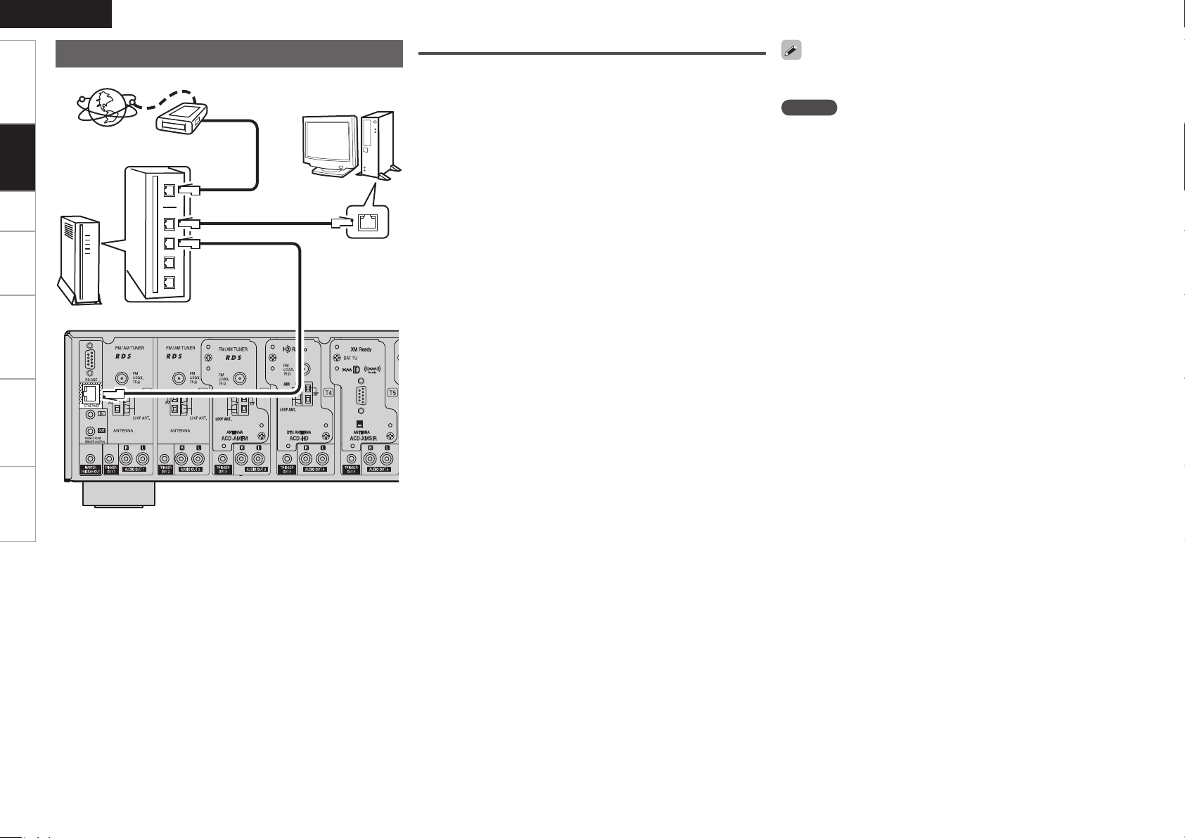
Connecting the Network
Connections
Internet
Router
Modem
To WAN side
To LAN port
To LAN port
Computer
LAN port /
Ethernet
connector
Required System
n Broadband Internet Connection
A broadband line connection to the Internet is required in order to
use the TU-604CI’s firmware update.
n Modem
This is a device that is connected to the broadband line to
communicate with the Internet. Some are integrated with the
router.
n Router
• When using the TU-604CI, we recommend you use a router
equipped with the following functions:
· Built-in DHCP (Dynamic Host Configuration Protocol) server.
This function automatically assigns IP addresses on the LAN.
· Built-in 100 BASE-TX switch.
When connecting multiple devices, we recommend a switching
hub with a speed of 100 Mbps or greater.
n Ethernet Cable (CAT-5 or greater recommended)
• The TU-604CI does not come with an Ethernet cable.
• Some flat type Ethernet cables are easily affected by noise.
We recommend using a normal type cable.
• If the sound is broken in an environment in which there is much
power supply noise from electric products or in a noisy network
environment, use a shielded type Ethernet cable (For North
America model).
• For the Ethernet cable, used a shielded twisted pair (STP) cable.
Do not use an unshielded twisted pair (UTP) cable, as it may exceed
noise standard limits (For Europe model).
n Computer
A computer with the following specifications is required to use a
server:
• OS
Windows® XP Service Pack2, Windows Vista
• Internet browser
Microsoft Internet Explorer 5.01 or later
• LAN port
For connections to the Internet, contact an ISP (Internet Service
Provider) or a computer shop.
NOTE
• A contract with an ISP is required to connect to the Internet.
No additional contract is needed if you already have a broadband
connection to the Internet.
• The types of routers that can be used depend on the ISP. Contact an
ISP or a computer shop for details.
n Others
• If you have an Internet provider contract for a line on which network
settings are made manually, make the settings at “Network Setup”
(vpage 17).
• With the TU-604CI, it is possible to use the DHCP and Auto IP
functions to make the network settings automatically.
• When using a broadband router (DHCP function), the TU-604CI
sets the IP address, etc., automatically.
When using the TU-604CI connected to a network with no DHCP
function, make the settings for the IP address, etc., at “Network
Setup” (vpage 17).
• The TU-604CI is not compatible with PPPoE. A PPPoE-compatible
router is required if you have a contract for a line of the type with
which the PPPoE is set.
 Loading...