

Page 1

DENON POA-A1HD control protocol
Application model : POA-A1HD
Application terminal: RS-232C
Connector specification
Ⅰ. RS-232C
Connector type: DB-9pin female type, slave straight connection (DCE type)
( 1pin : GND , 2pin : TxD , 3pin : RxD , 5pin : Common(GND) , 4,6,7,8,9pin : NC )
Communication format:
Synchronous system : Tone step synchronization
Communication system : A half duplex
Communication speed : 9600bps
Character length : 8 bits
Parity control : None
Start bit : 1 bit
Stop bit : 1 bit
Communication procedure : Non procedural
Communication data length : 135 bytes (maximum)
Ver. 1.0.7
- 1 -
Page 2
Protocol specification
The following three data forms are defined.
COMMAND : The message sent to a system(POA) from a controller(Touch Panel etc.)
A command to a system is given from a controller.
EVENT : The message sent to a controller (Touch Panel etc.) from a system (POA)
The result is sent, when a system is operated directly and a state changes.
*The form of EVENT presupposes that it is the same as that of COMMAND.
**Refer to the following table for the contents of COMMAND and EVENT.
RESPONSE : The message sent to a controller (Touch Panel etc.) from a system (POA)
if the ‘request command’ (COMMAND+?+CR(0x0D)) has came from a controller.
The RESPONSE should be sent within 200ms
*The form of RESPONSE presupposes that it is the same as that of EVENT.
of receiving the COMMAND.
Basic specification: The command by ASCII CODE, parameter expression
*ASCII CODE which can be used is from 0x20 to 0x7F: the alphabet and the number of 0-9, and space (0x20), some signs,
AND carriage return (0x0D) --- It is used only as a pause sign.
Command structure: COMMAND + PARAMETER + CR (0x0D)
COMMAND :ASCII CODE of 2 characters
PA :Power AMP(POA)Control
PARAMETER :ASCII CODE (up to 25 characters)
EX.PWON :Power On
Others
A) COMMAND is receivable also during transmission of EVENT.
B) The RESPONSE should be sent as opposed to the request command by all the commands with which an EVENT
exists not need to the another request commands.
C) Please set the input channel after setting the power amp.
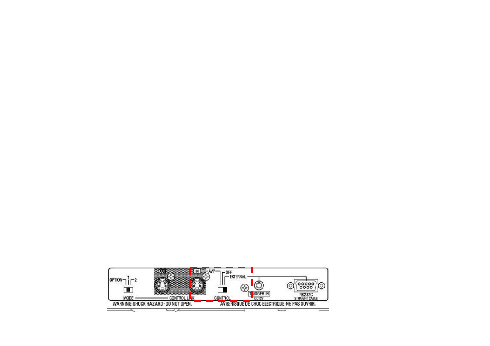
D) Please Power on it after making the CONTROL switch of POA-A1HD EXTERNAL
- 2 -
Page 3

COMMAND and PARAMETER list
COMMAND PARAMETER
PA PWON POA POWER ON/STANDBY change
PWSTBY
PW? Return PW Status
INL1RCA
INL1XLR
INL2OFF
INL2XLR
INL3OFF
INL3RCA
INL3XLR
INL4OFF
INL4RCA
INL4XLR
INL5OFF
INL5RCA
INL5XLR
INR1OFF
INR1RCA
INR1XLR
INR2OFF
INR2RCA
INR2XLR
INR3OFF
INR3RCA
INR3XLR
INR4OFF
INR4RCA
INR4XLR
INR5OFF
INR5RCA
INL1OFF Input Channel L* Setting
INL2RCA
INR5XLR
Input Channel R* Setting
function Example
PAPWON<CR>
PAPWSTBY<CR>
PAPW?<CR>
PAINL1OFF<CR>
PAINL1RCA<CR>
PAINL1XLR<CR>
PAINL2OFF<CR>
PAINL2RCA<CR>
PAINL2XLR<CR>
PAINL3OFF<CR>
PAINL3RCA<CR>
PAINL3XLR<CR>
PAINL4OFF<CR>
PAINL4RCA<CR>
PAINL4XLR<CR>
PAINL5OFF<CR>
PAINL5RCA<CR>
PAINL5XLR<CR>
PAINR1OFF<CR>
PAINR1RCA<CR>
PAINR1XLR<CR>
PAINR2OFF<CR>
PAINR2RCA<CR>
PAINR2XLR<CR>
PAINR3OFF<CR>
PAINR3RCA<CR>
PAINR3XLR<CR>
PAINR4OFF<CR>
PAINR4RCA<CR>
PAINR4XLR<CR>
PAINR5OFF<CR>
PAINL2OFF<CR>
PAINL2RCA<CR>
- 3 -
Page 4

COMMAND PARAMETER
PA IN? Return Channel setting
INL1?
INL2?
INL3?
INL5?
INR1?
INR3?
INR4?
INR5?
AMPL12NRM
AMPL12BAP
AMPL12BTL
AMPL34NRM
AMPL34BAP
AMPL34BTL
AMPLR5NRM
AMPLR5BAP
AMPLR5BTL
AMPR12BAP
AMPR12BTL
AMPR34NRM
AMP? Return Power Amp setting
AMPL12?
AMPL34?
AMPLR5?
AMPR12?
INL4?
INR2?
AMPR12NRM
AMPR34BAP
AMPR34BTL
AMPR34?
Return Channel L* setting
Return Channel R* setting
L1/L2 Power Amp setting
L3/L4 Power Amp setting
L5/R5 Power Amp setting
R1/R2 Power Amp setting
R3/R4 Power Amp setting
Return * Power Amp setting
function Example
PAIN?<CR>
PAINL1?<CR>
PAINL2?<CR>
PAINL3?<CR>
PAINL4?<CR>
PAINL5?<CR>
PAINR1?<CR>
PAINR2?<CR>
PAINR3?<CR>
PAINR4?<CR>
PAINR5?<CR>
PAAMPL12NRM<CR>
PAAMPL12BAP<CR>
PAAMPL12BTL<CR>
PAAMPL34NRM<CR>
PAAMPL34BAP<CR>
PAAMPL34BTL<CR>
PAAMPLR5NRM<CR>
PAAMPLR5BAP<CR>
PAAMPLR5BTL<CR>
PAAMPR12NRM<CR>
PAAMPR12BAP<CR>
PAAMPR12BTL<CR>
PAAMPR34NRM<CR>
PAAMPR34BAP<CR>
PAAMPR34BTL<CR>
PAAMP?<CR>
PAAMPL12?<CR>
PAAMPL34?<CR>
PAAMPLR5?<CR>
PAAMPR12?<CR>
PAAMPR34?<CR>
- 4 -
Page 5

※ PAIN?<CR> :RESPONSE becomes the following order.
State of input channel L1 –>State of L2 -> State of L3 -> State of L4 -> State of L5 ->
State of R5 -> State of R4 -> State of R3 -> State of R2 -> State of R1
PAINL1xxx<CR> PAINL2xxx<CR>PAINL3xxx<CR>PAINL4xxx<CR>PAINL5xxx<CR>
PAINR5xxx<CR>PAINR4xxx<CR>PAINR3xxx<CR>PAINR2xxx<CR>PAINR1xxx<CR>
(xxx ; "OFF" or "RCA" or "XLR")
※ PAAMP?<CR> :RESPONSE becomes the following order.
State of Power AMP channel L1/L2 -> State of L3/L4 -> State of L5/R5 ->
State of R4/R3 -> State of R2/R1
PAAMPL12xxx<CR> PAAMPL34xxx<CR>PAAMPLR5xxx<CR>PAAMPR34xxx<CR>PAAMPR12xxx<CR>
(xxx ; "NRM" or "BAP" or "BTL")
- 5 -
Page 6

COMMAND PARAMETER
PA
※ PAMT?<CR> :RESPONSE becomes the following order.
MTON Meter setting on PAMTON<CR>
MTOFF Meter setting off PAMTOFF<CR>
MTLCHG Left Meter setting PAMTLCHG<CR>
MTCCHG Center Meter setting PAMTCCHG<CR>
MTRCHG Right Meter setting PAMTRCHG<CR>
MT? Return Meter setting PAMT?<CR>
MTO? Return Meter On/Off setting PAMTO?<CR>
MTL? Return Left Meter setting PAMTL?<CR>
MTC? Return Center Meter setting PAMTC?<CR>
MTR? Return Right Meter setting PAMTR?<CR>
Return Meter On/Off setting PAMTxxx<CR> (xxx ; "ON" or "OFF")
Return Left Meter setting PAMTLx<CR> (x ; "1"~"4" or "NONE")
Return Center Meter setting PAMTxx<CR> (xx ; "L5" or "R5" or "CNONE")
Return Right Meter setting PAMTRx<CR> (x ; "1"~"4" or "NONE")
function Example
- 6 -
Page 7

EVENT(or RESPONSE) and PARAMETER list
EVENT PARAMETER
PA PWON POA POWER ON/STANDBY change
PWSTBY POA Standby status
PWPROTECT POA Protection status
INL1RCA
INL1XLR
INL2OFF
INL2XLR
INL3OFF
INL3RCA
INL3XLR
INL4OFF
INL4RCA
INL4XLR
INL5OFF
INL5RCA
INL5XLR
INR1OFF
INR1RCA
INR1XLR
INR2OFF
INR2RCA
INR2XLR
INR3OFF
INR3RCA
INR3XLR
INR4OFF
INR4RCA
INR4XLR
INR5OFF
INR5RCA
INL1OFF Input Channel L* Information
INL2RCA
INR5XLR
Input Channel R* Information
function example
PAPWON<CR>
PAPWSTBY<CR>
PAPW?<CR>
PAINL1OFF<CR>
PAINL1RCA<CR>
PAINL1XLR<CR>
PAINL2OFF<CR>
PAINL2RCA<CR>
PAINL2XLR<CR>
PAINL3OFF<CR>
PAINL3RCA<CR>
PAINL3XLR<CR>
PAINL4OFF<CR>
PAINL4RCA<CR>
PAINL4XLR<CR>
PAINL5OFF<CR>
PAINL5RCA<CR>
PAINL5XLR<CR>
PAINR1OFF<CR>
PAINR1RCA<CR>
PAINR1XLR<CR>
PAINR2OFF<CR>
PAINR2RCA<CR>
PAINR2XLR<CR>
PAINR3OFF<CR>
PAINR3RCA<CR>
PAINR3XLR<CR>
PAINR4OFF<CR>
PAINR4RCA<CR>
PAINR4XLR<CR>
PAINR5OFF<CR>
PAINL2OFF<CR>
PAINL2RCA<CR>
- 7 -
Page 8

EVENT PARAMETER
PA AMPL12NRM PAAMPL12NRM<CR>
AMPL12BAP PAAMPL12BAP<CR>
AMPL12BTL
AMPL34BAP PAAMPL34BAP<CR>
AMPL34BTL
AMPLR5NRM PAAMPLR5NRM<CR>
AMPLR5BTL
AMPR12BTL
AMPR34NRM PAAMPR34NRM<CR>
AMPR34BAP PAAMPR34BAP<CR>
AMPR34BTL
PA MTON PAMTON<CR>
MTOFF
MTL1 PAMTL1<CR>
MTL2 PAMTL2<CR>
MTL3 PAMTL3<CR>
MTL4
MTL5 PAMTL5<CR>
MTR5
MTR1 PAMTR1<CR>
MTR2 PAMTR2<CR>
MTR3 PAMTR3<CR>
MTR4
MTLNONE PAMTLNONE<CR>
MTCNONE PAMTCNONE<CR>
AMPL34NRM PAAMPL34NRM<CR>
AMPLR5BAP PAAMPLR5BAP<CR>
AMPR12NRM PAAMPR12NRM<CR>
AMPR12BAP PAAMPR12BAP<CR>
MTRNONE
L1/L2 Power Amp Information
L3/L4 Power Amp Information
L5/R5 Power Amp Information
R1/R2 Power Amp Information
R3/R4 Power Amp Information
Meter Information
Left Meter Information
Center Meter Information
Right Meter Information
No left meter selection
No center meter selection
No right meter selection
function example
PAAMPL12BTL<CR>
PAAMPL34BTL<CR>
PAAMPLR5BTL<CR>
PAAMPR12BTL<CR>
PAAMPR34BTL<CR>
PAMTOFF<CR>
PAMTL4<CR>
PAMTR5<CR>
PAMTR4<CR>
PAMTRNONE<CR>
- 8 -
 Loading...