

Denon PMA-710AE Service Manual

D&M Holdings lnc.
e
Copyright 2011 D&M Holdings Inc. All rights reserved.
WARNING: Violators will be prosecuted to the maximum extent possible.
Ver. 8
●
For purposes of improvement, specifications and design are subject to change without notice.
●
Please use this service manual with referring to the operating instructions without fail.
●
Some illustrations using in this service manual are slightly different from the actual set.
Please refer to the
MODIFICATION NOTICE.
SERVICE MANUAL
MODEL JP E3 E2 EK E2A E1C E1K EUT
PMA-710AE
33
INTEGRATED STEREO AMPLIFIER
S0279-0V08DM/DG1105

Please heed the points listed below during servicing and inspection.
SAFETY PRECAUTIONS
The following check should be performed for the continued protection of the customer and service technician.
LEAKAGE CURRENT CHECK
Before returning the unit to the customer, make sure you make either (1) a leakage current check or (2) a line to chassis
resistance check. If the leakage current exceeds 0.5 milliamps, or if the resistance from chassis to either side of the
power cord is less than 460 kohms, the unit is defective.
CAUTION
CAUTION
◎ Heed the cautions!
Spots requiring particular attention when servicing, such
as the cabinet, parts, chassis, etc., have cautions indicated
on labels or seals. Be sure to heed these cautions and the
cautions indicated in the handling instructions.
◎ Caution concerning electric shock!
(1) An AC voltage is impressed on this set, so touching in-
ternal metal parts when the set is energized could
cause electric shock. Take care to avoid electric shock,
by for example using an isolating transformer and
gloves when servicing while the set is energize d, unplugging the power cord when replacing parts, etc.
(2)There are high voltage parts inside. Handle wi th extra
care when the set is energized.
◎ Caution concerning disassembly and
assembly!
Though great care is taken when manufacturing parts from
sheet metal, there may in some rare cases be burrs on the
edges of parts which could cause injury if fingers are
moved across them. Use gloves to protect your hands.
◎ Only use designated parts!
The set's parts have specific safety properties (fire resistance, voltage resistance, etc.). For replacement parts, be
sure to use parts which have the same properties. In particular, for the important safety parts that are marked z on
wiring diagrams and parts lists, be sure to use the designated parts.
◎ Be sure to mount parts and arrange
the wires as they were originally!
For safety reasons, some parts use tape, tubes or other insulating materials, and some parts are mounted away from
the surface of printed circuit boards. Care is also taken with
the positions of the wires inside and clamps are used to
keep wires away from heating and high voltage parts, so
be sure to set everything back as it was originally.
◎ Inspect for safety after servicing!
Check that all screws, parts and wires removed or disconnected for servicing have been put back in their original positions, inspect that no parts around the area that has been
serviced have been negatively affected, conduct an insulation check on the external metal connectors and between
the blades of the power plug, and otherwise ch eck that
safety is ensured.
(Insulation check procedure)
Unplug the power cord from the power outlet, disconnect
the antenna, plugs, etc., and turn the power switch on. Using a 500V insulation resistance tester, check that the insulation resistance between the terminals of the power
plug and the externally exposed metal parts (antenna terminal, headphones terminal, microphone terminal, input
terminal, etc.) is 1MΩ or greater. If it is less, the set must
be inspected and repaired.
Concerning important safety
parts
Many of the electric and structural parts used in the set
have special safety properties. In most cases these properties are difficult to distinguish by sight, and using replacement parts with higher ratings (rated power and
withstand voltage) does not necessarily guarantee that
safety performance will be preserved. Parts with safety
properties are indicated as shown below on the wiring diagrams and parts lists is this service manual. Be sure to replace them with parts with the designated part number.
(1) Schematic diagrams ... Indicated by the z mark.
(2) Parts lists ... Indicated by the z mark.
Using parts other than the designated
parts could result in electric shock, fires or
other dangerous situations.
2
PMA-710AE

DIMENSION
344
434
60
102.520
26520.5
23
max
50.5 165.5 49
344
3
PMA-710AE
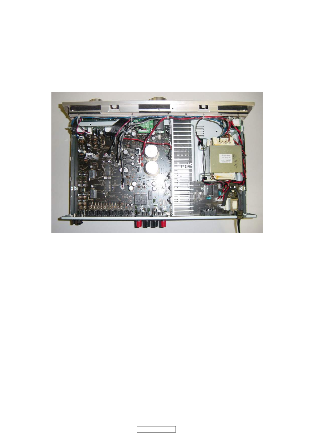
WIRE ARRANGEMENT
Front Panel side
Back Panel side
If wire bundles are untied or moved to perform adjustment or parts replacement etc.,be sure to rearrange them neatly as
they were originally bundled or placed afterward.
Otherwise, incorrect arrangement can be a cause of noise generation.
Wire arrangement viewed from the top
4
PMA-710AE
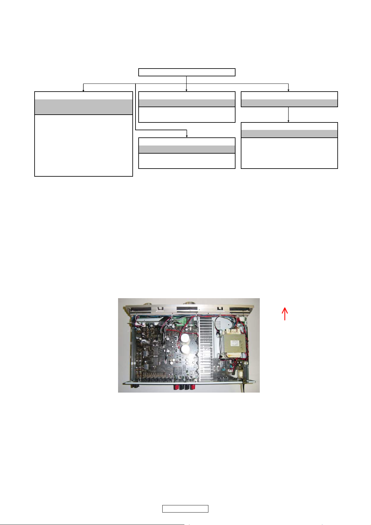
DISASSEMBLY
TOP CABINET
FRONT PANEL ASSY POWER PCB REAR PANEL
Refer to "DISASSEMBLY 1.FRONT PANEL ASSY" Refer to "EXPLODED VIEW" Refer to "EXPLODED VIEW"
and "EXPLODED VIEW" POWER PCB
FRONT PCB (Ref. No. of EXPLODED VIEW : 1-2)
(Ref. No. of EXPLODED VIEW : 2-1)
MAIN PCB ASSY
FUNCTION PCB Refer to "EXPLODED VIEW"
(Ref. No. of EXPLODED VIEW : 2-3)
POWER TRANSFORMER
MAIN PCB ASSY
VOLUME PCB Refer to "EXPLODED VIEW" (Ref. No. of EXPLODED VIEW : 1-1)
(Ref. No. of EXPLODED VIEW : 2-4) POWER TRANSFORMER MCU PCB ASSY
SW/HP PCB (Ref. No. of EXPLODED VIEW : 28) (Ref. No. of EXPLODED VIEW : 2-2)
(Ref. No. of EXPLODED VIEW : 2-5)
The viewpoint of each photograph
(Photografy direction)
[View from above]
Front side
• Disassemble in order of the arrow of the figure of following flow.
• In the case of the re-assembling, assemble it in order of the reverse of the following flow.
• In the case of the re-assembling, observe "attention of assembling" it.
About the photos used for descriptions in the “DISASSEMBLY” section.
• The direction from which the photographs used herein were photograph ed is indicated at "Direction of photograph: ***" at
the left of the respective photographs.
• Refer to the table below for a description of the direction in which the photos were taken.
• Photographs for which no direction is indicated were taken from above the product.
PMA-710AE
5

1. FRONT PANEL ASSY
Proceeding : CABINET TOP FRONT PANEL ASSY
→
View from bottom
Style pin : Loose
cut
CN52 CN53 CN95
CN92
CN94CN50CN55
CN51
CN93
CN94
Please refer to "EXPLODED VIEW" for the disassembly method of each P.W.B included in FRONT PANEL ASSY.
(1) Remove the screws.
(2) Cut the wire clamp bands, then loose the style pins.
(3) Disconnect the connector wires, then remove the screws.
6
PMA-710AE
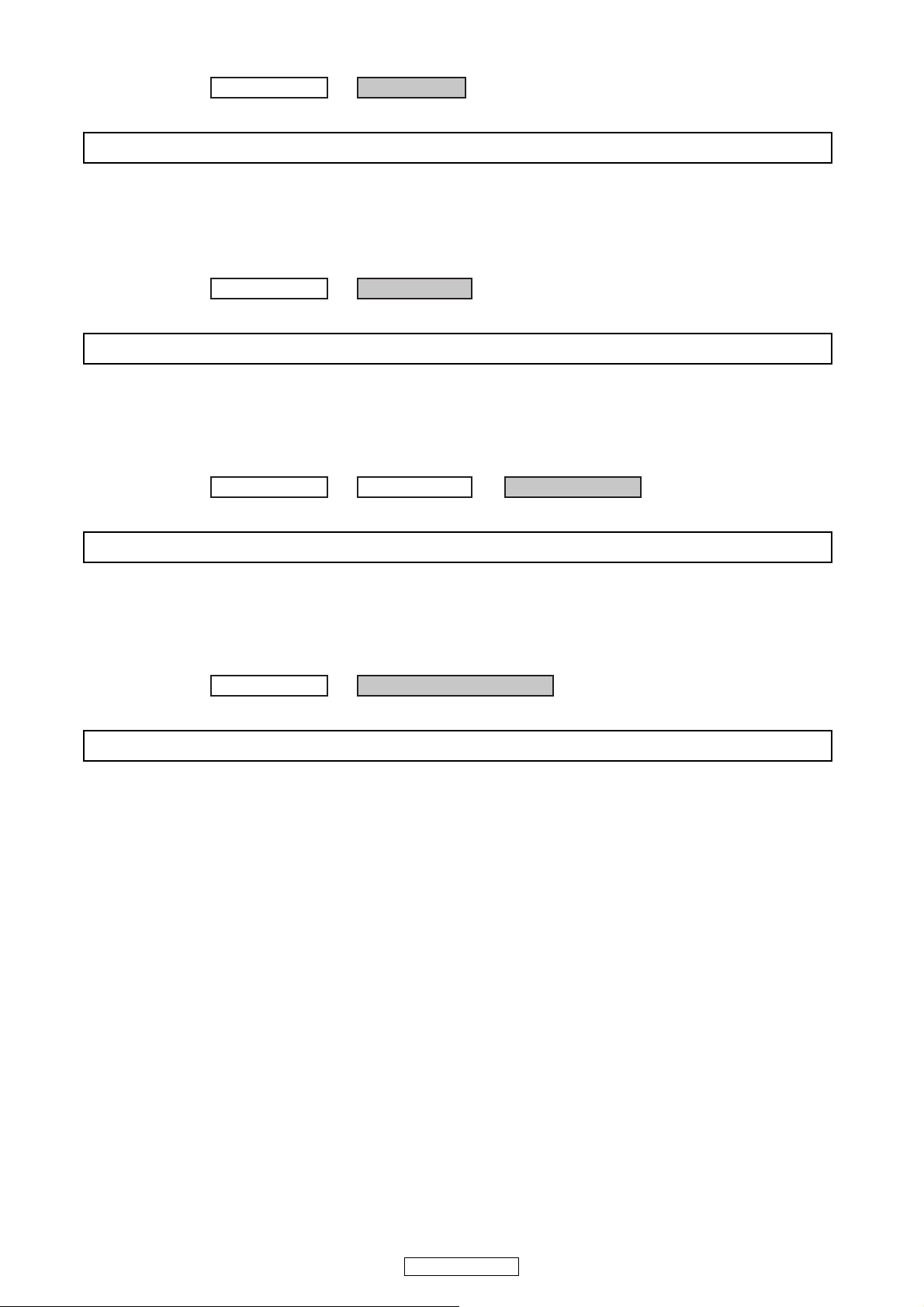
2. POWER PCB
Proceeding : TOP CABINET POWER PCB
→
Please refer to "EXPLODED VIEW" for the disassembly method in POWER PCB.
Proceeding : TOP CABINET REAR PANEL
→
Please refer to "EXPLODED VIEW" for the disassembly method in REAR PANEL.
Proceeding : TOP CABINET REAR PANEL
→
MAIN PCB ASSY
→
Please refer to "EXPLODED VIEW" for the disassembly method in MAIN PCB ASSY.
Proceeding : TOP CABINET POWER TRANSFORMER
→
Please refer to "EXPLODED VIEW" for the disassembly method in POWER TRANSFORMAER.
3. REAR PANEL
4. MAIN PCB ASSY
5. POWER TRANSFORMER
7
PMA-710AE
BLOCK AND LEVEL DIAGRAM
EQ
TONE
&
LOUDNESS
SOURCE DIRECT
BALANCE
BUFFER
MAIN VOLUME
POWER AMP
SPEAKER A
SPEAKER B
PHONO
CD
TUNER
LINE
44dB
HEADPHONE
35.5dB(MM)
VOLATAGE
REGULATOR
POWER AMP
OUTPUT STAGE
±16V
±16V
±16V
PHONO EQ
TONE
POWER AMP
FIRST STAGE
CONTROL
&
RELAY
STANDBY
30dB
20dB
10dB
0dB
-10dB
-20dB
-30dB
-40dB
-50dB
-60dB
-70dB
CD etc. 100mV(-20dB)
MM 1.7mV(-55.4dB)
50W/8ohm 20.0V(25.5dB)
AC CORD
PRE OUT
0.7V/10k ohm(-3dB)
INPUT
RECODER-1RECODER-2
PREOUT
PB
REC
PB
REC
2
4
3
1
2
4
3
1
PMA-710AE
8

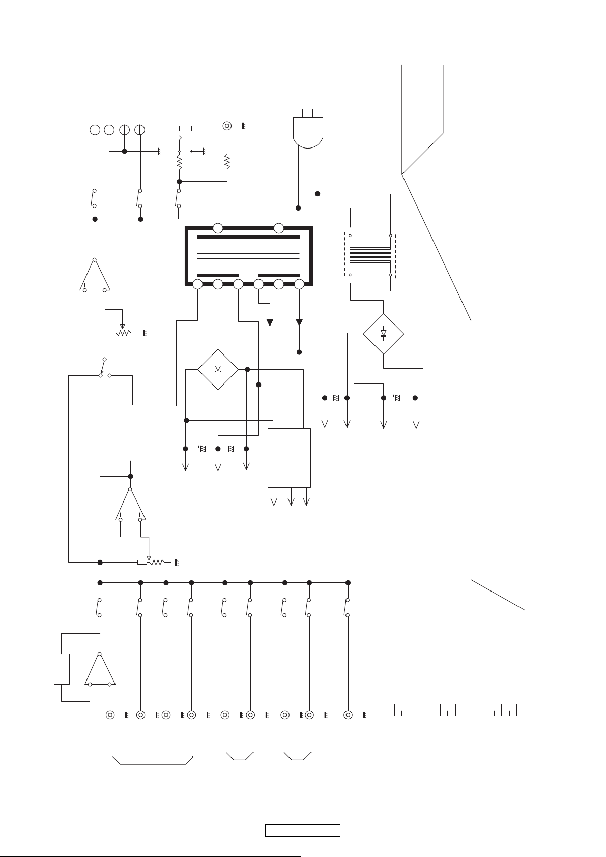
ADJUSTMENT
VR31
CN31
CN32
VR32
Volume
DC Voltmeter
Power
Trans
Idling Current
Required measurement equipment: DC Voltmeter
1. Setup
(1) Place the unit at an ordinary position avoiding direct air flow from an air-conditioner or fan. Do the adjustment at a tem-
perature between 15 °C (59 °F) and 30 °C (86 °F).
(2) Set control as follows.
• POWER switch → OFF (j).
• VOLUME control → fully counterclockwise ( c min.)
• SPEAKER terminals → open: do not connect the speakers, dummy load etc.
2. Adjustment
(1) Remove top cover. And then connect DC Voltmeter to the test points CN31 and CN32 of CUP12196B Main PCB.
(2) Connect power cord to AC wall outlet, and turn POWER switch "ON" ( h ).
(3) Right after power on, adjust VR31 and VR32 so that the DC voltmeter reads 10 ±1mV.
(4) Then after 2 minutes warm up adjust VR31 and VR32 so that the DC voltmeter reads 10 ±1mV.
(5) And after 10 minutes warm up adjust VR31 and VR32 so that the DC voltmeter reads 10 ±0.5mV.
9
PMA-710AE
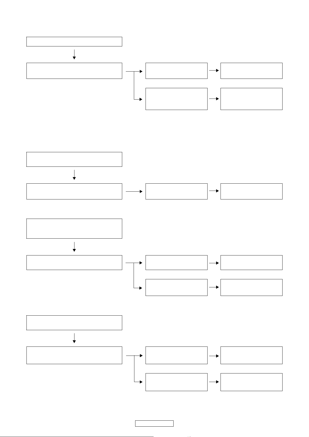
TROUBLE SHOOTING
1. The power can not be turned on. (Power indication LED does not light.)
Check the insertion of the Power Part.
Check whether power is being supplied to the coil
of the standby transformer (T901).
Power not supplied.
Power supplied.
Broken wire in standby transformer (T901)
Malfunction of D941-944, C941
or C943.
2. The power turned on, but a sound does not output normally. (Both channels)
2.1.
Set remains in standby mode with power indicator
LED lit red.
Check each connector.
2.2.
The connectors are inserted
completely.
Malfunction of RC71 or IC41.
Power indicator LED remains flashing red and
muting mode is not canceled (protection mode is
set).
Check the power amplifier output's offset voltage.
2.3.
Set operates, but then power indicator LED
flashes red (protection mode is set).
Check the power amplifier output's offset voltage.
Offset voltage output is 1V or
greater.
No offset voltage is output.
Offset voltage output is 1V or
greater.
Damaged power amplifier circuit.
Damaged temperature detection circuit or protection circuit.
Damaged power amplifier circuit.
No offset voltage is output. Check the bias current.
10
PMA-710AE
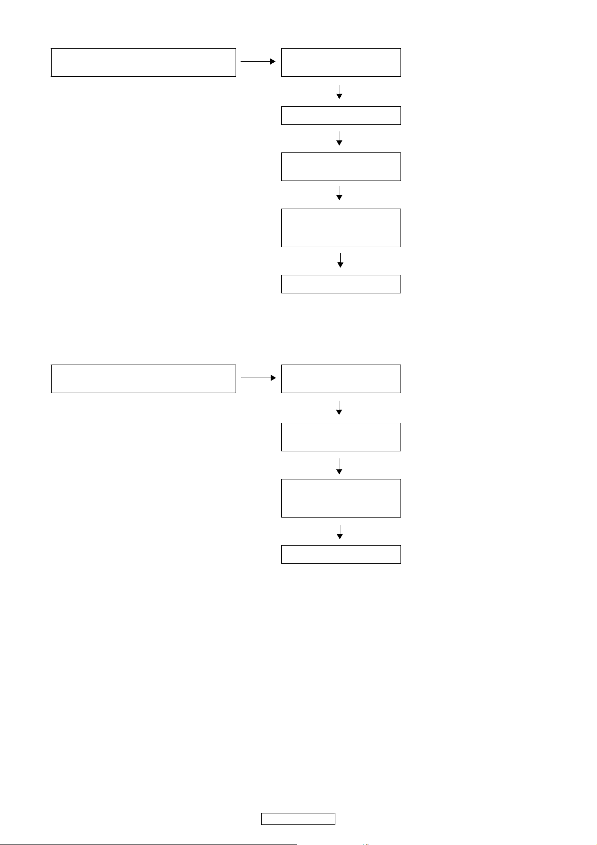
2.4.
Power indicator LED is lit normally (green or
orange).
Check each connector.
Is the fuse (F901) normal?
Check the voltage of each
department.
Check the operation of the
switching relay, switching IC
and speaker relay.
Check the Signal line.
3. The power turned on, but a sound does not output normally. (Single channel)
Power indicator LED is lit normally (green or
orange).
Check each connector.
Check the voltage of each
department.
Check the operation of the
switching relay, switching IC
and speaker relay.
Check the Signal line.
11
PMA-710AE
 Loading...