

Denon PMA-600NE Black User manual
Contents
.
Connections Playback Settings Tips Appendix
PMA-600NE
INTEGRATED AMPLIFIER
Owner’s Manual
.
Front panel Rear panel
Remote control
unit
1
Index
Contents Connections Playback Settings Tips Appendix
Accessories
Inserting the batteries
Operating range of the remote control unit
Features
High quality sound
High performance
Part names and functions
Front panel
Rear panel
Remote control unit
Connections
Connecting speakers
Subwoofer connection
Speaker connection
Connecting a playback device
Connecting a recording device
Connecting to a device with digital audio output connectors
Connecting the power cord
4
Playback
5
Turning the power on
5
Switching the power to standby
6
Selecting the input source
6
Adjusting the volume
6
Turning off the sound temporarily (Muting)
7
Adjusting the tone
7
10
12
17
18
18
19
20
21
22
Playing CDs
Listening to music on a Bluetooth device
Connecting and playing back from a digital device (Coaxial/
Optical)
Recording
Settings
Setting the Auto Standby mode
24
24
25
25
25
25
26
28
30
31
32
Front panel Rear panel
Remote control
unit
2
Index
Contents Connections Playback Settings Tips Appendix
Tips
Tips
Troubleshooting
Power does not turn on / Power is turned off
Operations cannot be performed through the remote control unit
No sound comes out
Desired sound does not come out
Sound is interrupted or noise occurs
Bluetooth cannot be played back
Audio from digital devices cannot be played back (Coaxial/
Optical)
34
35
36
37
38
39
40
41
42
Appendix
D/A converter
Playing back a Bluetooth device
Explanation of terms
Trademark information
Specifications
Index
43
43
44
45
46
51
Front panel Rear panel
Remote control
unit
3
Index
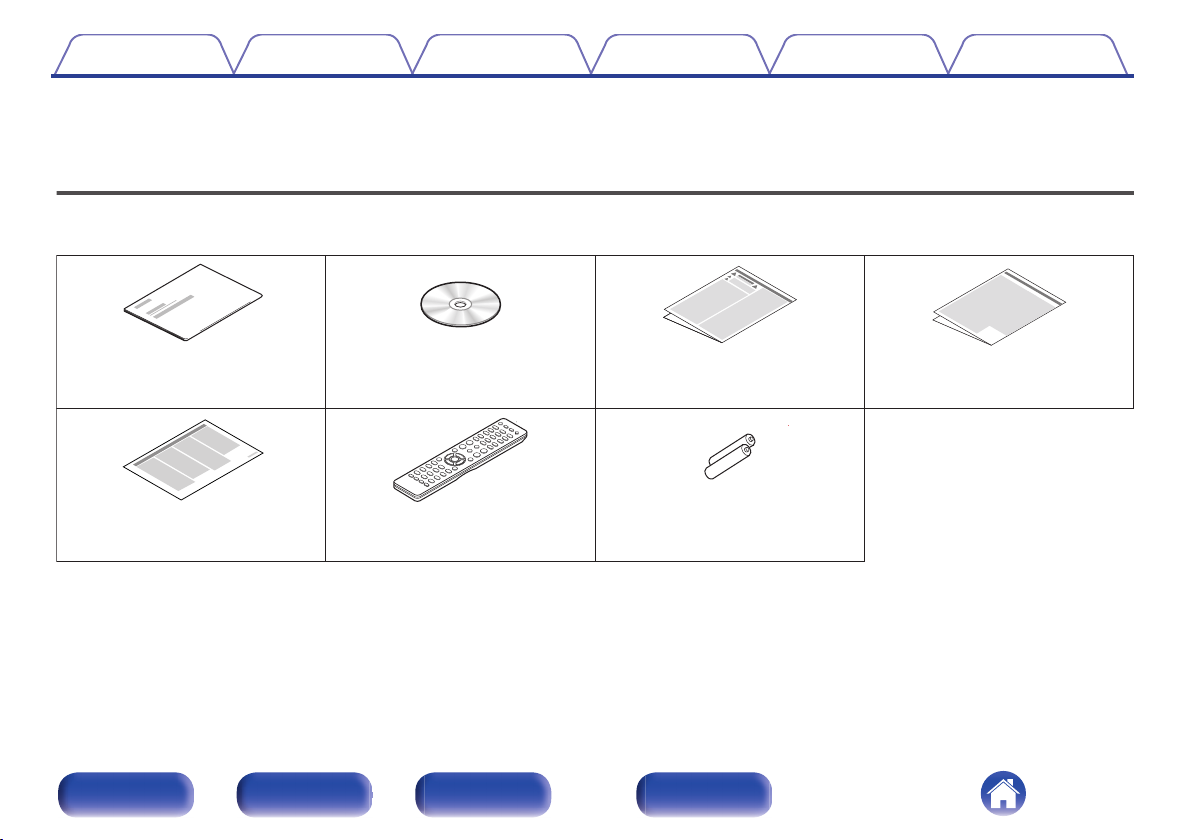
Quick Start Guide
CD-ROM
(Owner’s Manual)
Safety Instructions
Cautions on Using Batteries
R03/AAA batteries
Remote control unit
(RC-1234)
Notes on radio
Contents Connections Playback Settings Tips Appendix
Thank you for purchasing this Denon product. To ensure proper operation, please read this owner’s manual carefully before using the product.
After reading this manual, be sure to keep it for future reference.
Accessories
Check that the following parts are supplied with the product.
.
Front panel Rear panel
Remote control
unit
4
Index
Batteries
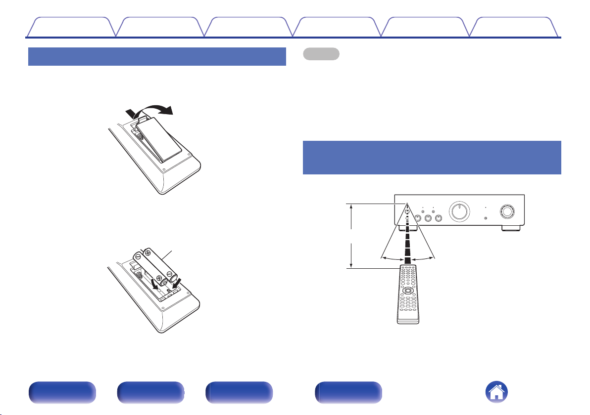
30°
Approx. 7 m
30°
Contents
Connections Playback Settings Tips Appendix
1
2
3
Inserting the batteries
Remove the rear lid in the direction of the arrow and
remove it.
.
Insert two batteries correctly into the battery
compartment as indicated.
.
Put the rear cover back on.
NOTE
To prevent damage or leakage of battery fluid:
0
Do not use a new battery together with an old one.
0
Do not use two different types of batteries.
0
Remove the batteries from the remote control unit if it will not be in use for long
0
periods.
If the battery fluid should leak, carefully wipe the fluid off the inside of the battery
0
compartment and insert new batteries.
Operating range of the remote control
unit
Point the remote control unit at the remote sensor when operating it.
.
Front panel Rear panel
Remote control
unit
5
Index
Contents Connections Playback Settings Tips Appendix
Features
High quality sound
Equipped with an advanced high current single push-pull circuit
0
that achieves a perfect balance of delicacy with power
This unit is equipped with a HC transistor that allows a peak current that
is two to three times that of an ordinary audio power transistor, enabling
clear and stable musical expression from minute sound to high
volumes.
High performance
DIGITAL AUDIO IN connectors (COAXIAL/OPTICAL)
0
You can play back PCM signals up to 192 kHz/24 bits by inputting digital
audio signals from an external device into this unit.
Phono input connectors for turntables
0
This unit is equipped with a phono amplifier so that you can directly
connect a turntable and play records. (Only the MM cartridge can be
used.)
Front panel Rear panel
Remote control
unit
6
Index
rueqw
y
t
i
Q
1
Q
2
Q
3
Q
5
Q
0
o Q
6
Q
4
Contents
Connections Playback Settings Tips Appendix
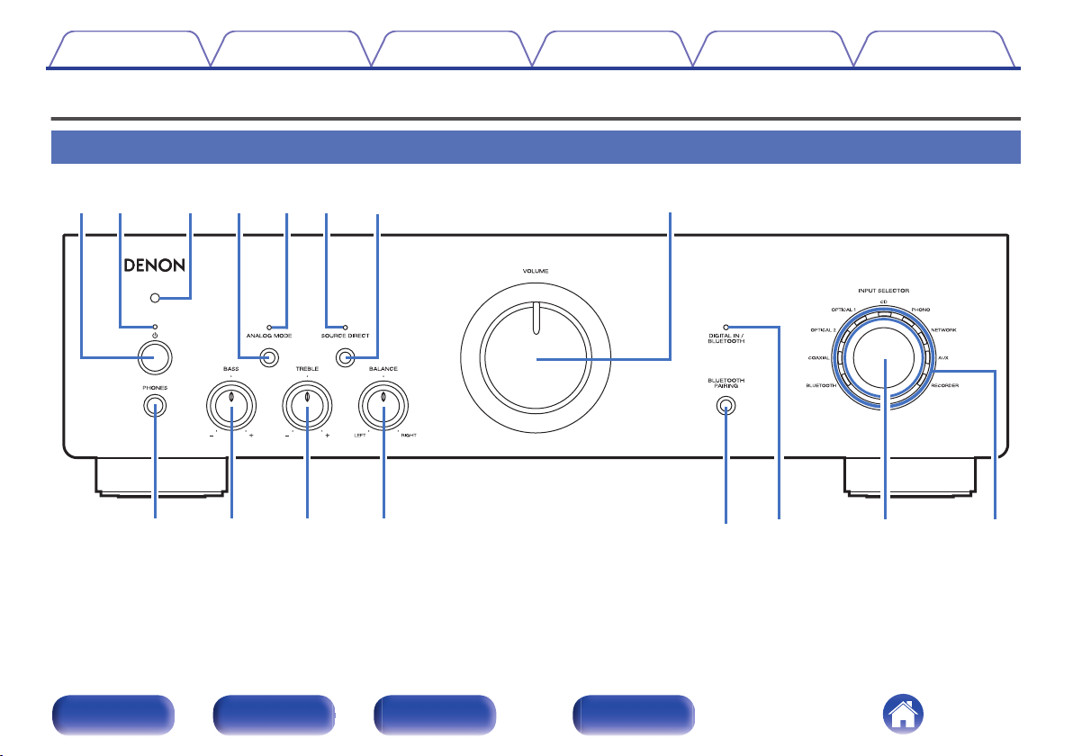
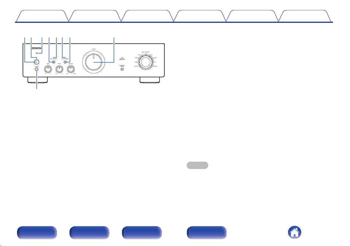
Part names and functions
Front panel
Remote control
unit
7
.
For details, see the next page.
Front panel Rear panel
Index
rueyt
i
qw
o
Contents Connections Playback Settings Tips Appendix
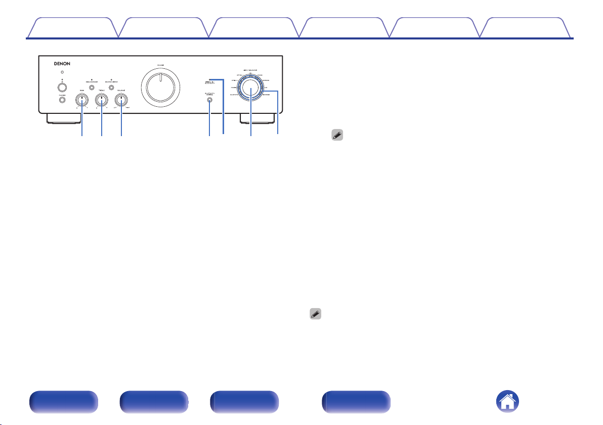
ANALOG MODE button
D
This turns the analog mode on/off.
(v p. 27)
ANALOG MODE indicator
E
This is displayed as follows, according to the analog mode status.
Lit in green: Analog mode on
0
Off: Analog mode off
0
SOURCE DIRECT indicator
F
This is displayed as follows according to the source direct status.
Lit in green: Source direct mode on
.
Power operation button (X)
A
This turns the power on/off. (v p. 24)
Power indicator
B
This is displayed as follows according to the power status:
Lit in green: Power on
0
Lit in red: Bluetooth standby (v p. 27)
0
Off: Normal standby
0
Remote control sensor
C
This receives signals from the remote control unit. (v p. 5)
0
Off: Source direct mode off
0
SOURCE DIRECT button
G
This turns source direct mode on/off. (v p. 26)
VOLUME knob
H
This adjusts the volume level. (v p. 25)
Headphones jack (PHONES)
I
Used to connect headphones.
When the headphones are plugged into this jack, audio will no longer
be output from the connected speakers or from the PRE OUT
connectors.
NOTE
To prevent hearing loss, do not raise the volume level excessively when using
0
headphones.
Front panel Rear panel
Remote control
unit
8
Index
Q1Q
2
Q
3
Q
0
Q5Q
6
Q
4
Contents Connections Playback Settings Tips Appendix
DIGITAL IN/BLUETOOTH indicator
N
This is displayed as follows, according to the status of the digital
0
audio signals that are input to the digital audio input terminals on this
unit.
Lit in green: Playback is supported on this unit
0
Blinking in green: Playback is not supported on this unit
0
Off: Sampling frequency cannot be detected
0
.
BASS control knob
J
This setting adjusts the volume level for the bass. (v p. 25)
TREBLE control knob
K
This setting adjusts the volume level for the treble. (v p. 25)
BALANCE control knob
L
This adjusts the balance of the volume output from the left and right
speakers. (v p. 25)
BLUETOOTH/PAIRING button
M
This switches the input source to “BLUETOOTH”. It is also pressed
during the pairing operation. (v p. 28)
Front panel Rear panel
Remote control
unit
For details on the audio signal specifications that are compatible with this
0
unit, see “D/A converter” (v p. 43).
This is displayed as follows according to the Bluetooth connection
0
status:
Blinking in blue (intervals of about 1 second): Pairing mode
0
Blinking in blue (intervals of about 2 seconds): Searching mode
0
(searching for a paired Bluetooth device and attempting to
connect via Bluetooth)
Lit in blue: Connecting mode (a Bluetooth connection has been
0
made with a Bluetooth device)
Off: Waiting mode (a Bluetooth connection has not been made
0
with any Bluetooth device)
INPUT SELECTOR knob
O
This selects the input source. (v p. 25)
Input indicators (v p. 25)
P
0
0, a and b can be adjusted when 6 is off (SOURCE DIRECT mode is off).
9
Index
y i
er tqw
u
Contents
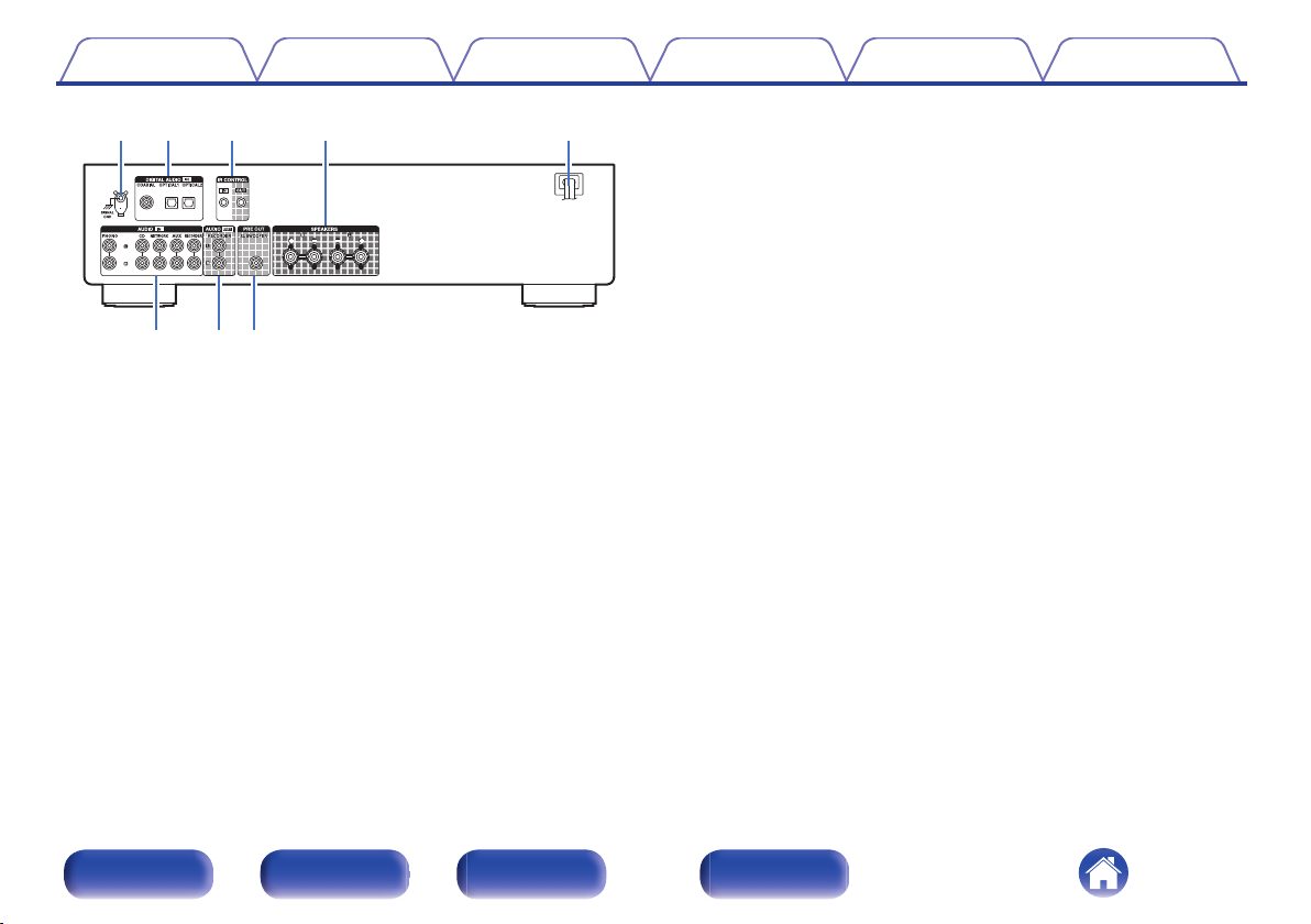
Rear panel
.
For details, see the next page.
Connections Playback Settings Tips Appendix
Front panel Rear panel
Remote control
unit
10
Index
y i
t
u
rqw e
Contents Connections Playback Settings Tips Appendix
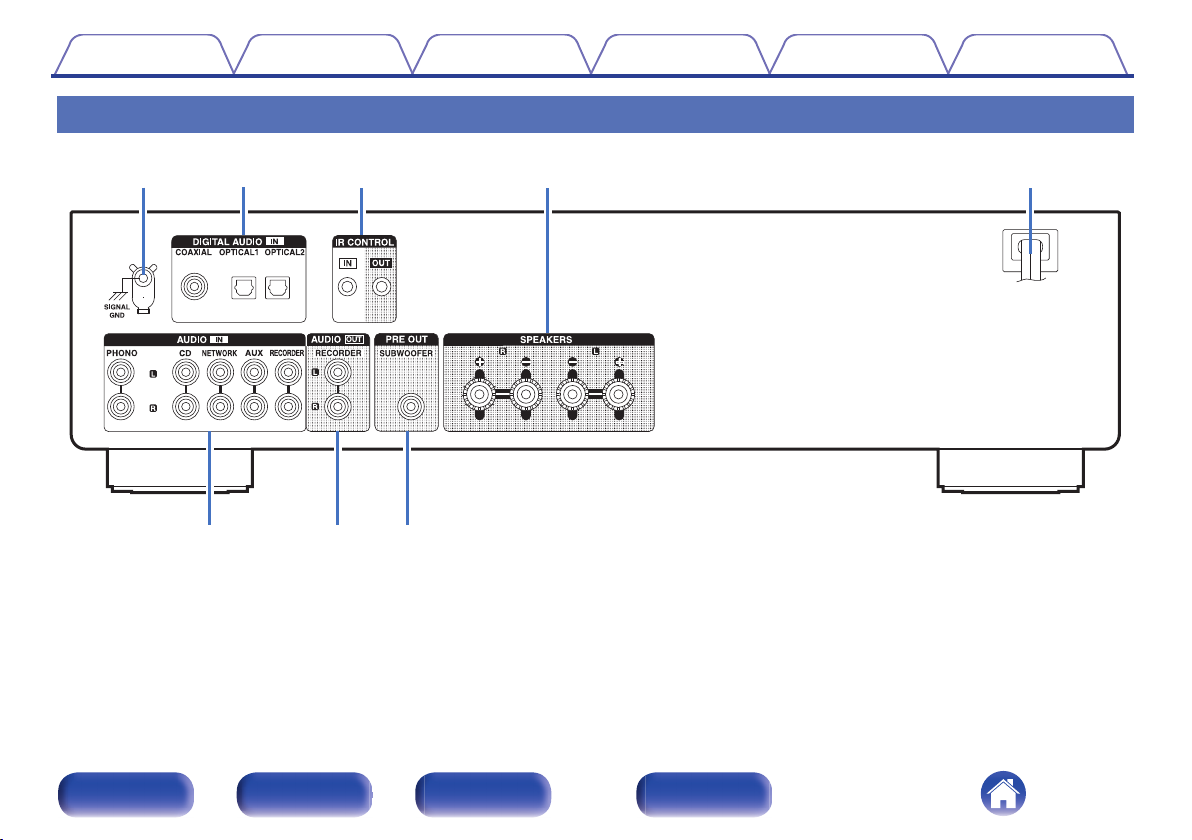
Analog audio connectors (AUDIO IN)
F
Used to connect devices equipped with analog audio output
connectors.
“Connecting a playback device” (v p. 19)
0
“Connecting a recording device” (v p. 20)
0
AUDIO OUT connectors
G
Used to connect the input connector of a recorder. (v p. 20)
PRE OUT connector
H
Used to connect a subwoofer with a built-in amplifier.
.
SIGNAL GND terminal
A
Used to connect the ground wire of a turntable.
(v p. 19)
DIGITAL AUDIO IN connectors
B
Used to connect devices equipped with digital audio output connectors.
(v p. 21)
IR CONTROL connectors
C
Used to connect Denon network audio players with an IR controller.
Speaker terminals (SPEAKERS)
D
Used to connect speakers. (v p. 17)
Power cord (v p. 22)
E
(v p. 18)
Front panel Rear panel
Remote control
unit
11
Index
w
e
r
t
q
Contents Connections Playback Settings Tips Appendix
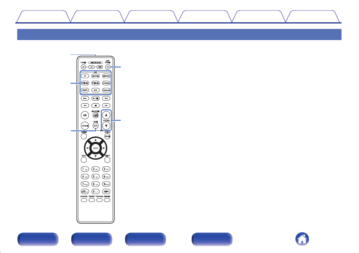
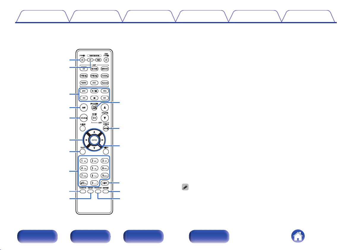
Remote control unit
The remote control provided with this unit can control a network audio
player in addition to a Denon CD player.
“CD player operations” (v p. 13)
0
“Network audio player operations” (v p. 14)
0
o
Operating this unit
Remote control signal transmitter
A
This transmits signals from the remote control unit. (v p. 5)
Input source select buttons
B
This selects the input source. (v p. 25)
MUTE button (:)
C
This mutes the output audio. (v p. 25)
Power operation button (AMP POWER X)
D
This turns the power on/off (standby).
(v p. 24)
VOLUME buttons (df)
E
These adjust the volume level. (v p. 25)
.
Front panel Rear panel
Remote control
unit
12
Index
w
e
q
r
t
i
o
Q0
y
u
Q4
Q2
Q5
Q6
Q3
Q1
Contents Connections Playback Settings Tips Appendix
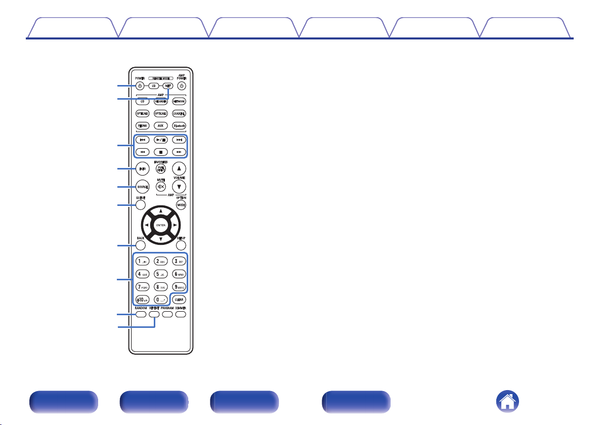
o
CD player operations
A Denon CD player can be operated.
To operate a CD player, press the REMOTE MODE CD button to
switch the remote control to the CD player operation mode.
Power operation button (POWER X)
A
Remote mode select button
B
(REMOTE MODE CD)
System buttons
C
Information button (INFO)
D
SOURCE button
E
Cursor buttons (uio p)
F
BACK button
G
Number/letter buttons (0 – 9, +10)
H
RANDOM button
I
REPEAT button
J
PURE DIRECT button
K
MODE button
L
ENTER button
M
CLEAR button
N
DIMMER button
O
PROGRAM button
P
The remote control may not operate some products.
0
Front panel Rear panel
Remote control
unit
13
Index
o
Q0
w
e
q
t
y
r
u
i
Contents Connections Playback Settings Tips Appendix
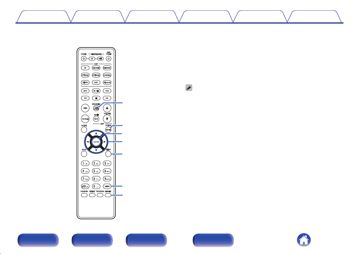
o
Network audio player operations
You can operate a Denon network audio player.
To operate a network audio player, press the REMOTE MODE NET
button to switch the remote control to the network audio player
operation mode.
Power operation button (POWER X)
A
Remote mode select button
B
(REMOTE MODE NET)
System buttons
C
Information button (INFO)
D
SOURCE button
E
QUEUE button
F
BACK button
G
Number/letter buttons (0 – 9, +10)
H
RANDOM button
I
REPEAT button
J
Front panel Rear panel
Remote control
unit
14
Index
Q2
Q1
Q3
Q4
Q5
Q6
Q7
Contents Connections Playback Settings Tips Appendix
FAVORITES button
K
OPTION button
L
ENTER button
M
Cursor buttons (uio p)
N
SETUP button
O
CLEAR button
P
DIMMER button
Q
The remote control may not operate some products.
0
Front panel Rear panel
Remote control
unit
15
Index
R
L
R
L
Contents Connections Playback Settings Tips Appendix
o
Contents
Connecting speakers 17
Connecting a playback device 19
Connecting a recording device 20
Connecting to a device with digital audio output connectors 21
Connecting the power cord 22
NOTE
Do not plug in the power cord until all connections have been completed.
0
Do not bundle power cords together with connection cables. Doing so can result in
0
humming or noise.
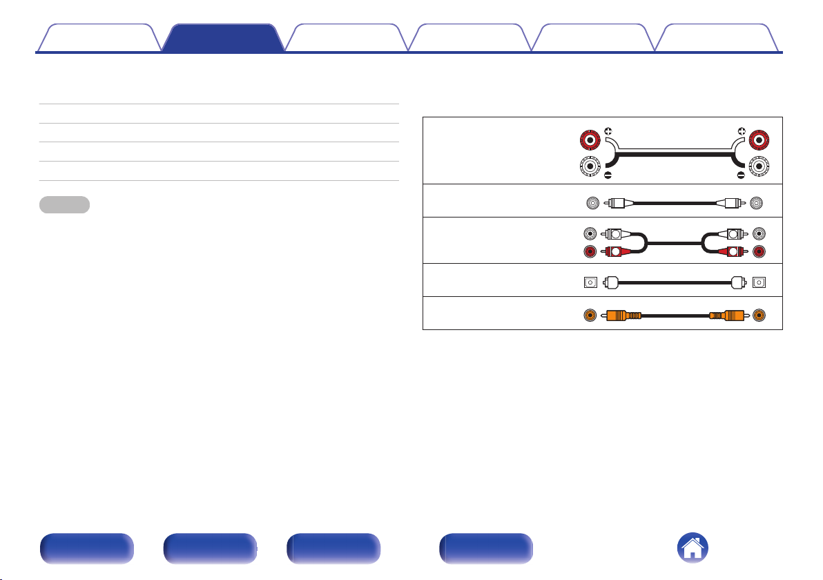
o
Cables used for connections
Provide necessary cables according to the devices you want to
connect.
Speaker cable
.
Subwoofer cable
.
Audio cable
.
Optical cable
Coaxial digital cable
.
.
Front panel Rear panel
Remote control
unit
16
Index
 Loading...