

Page 1
1
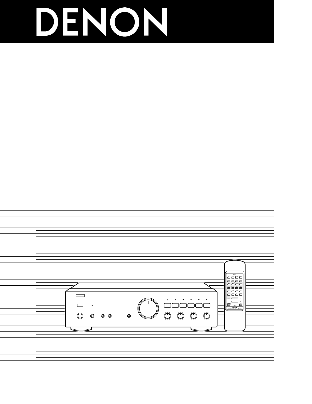
INTEGRATED STEREO AMPLIFIER
PMA-495R
OPERATING INSTRUCTIONS
BEDIENUNGSANLEITUNG
MODE D’EMPLOI
ISTRUZIONI PER L’USO
INSTRUCCIONES DE OPERACION
GEBRUIKSAANWIJZING
BRUKSANVISNING
INSTRUÇÕES DE OPERAÇÃO
B
REMOTE SENSOR MUTE / STANDBY
VOLUME
SOURCE
DIRECT
£
¢
ON
OFF
POWER
¢£
ON / STANDBY OFF
INTEGRATED STEREO AMPLIFIER
£¢
ON OFF
PHONES SPEAKERS
AB
PMA-495R
TAPE-2 / MD
COPY
TAPE-1 / CD-R
AUX TUNER CD PHONO
+–
+–
BALANCE BASS TREBLE
VARIABLE
LOUDNESS
LEFT
RIGHT
REMOTE SENSOR MUTE / STANDBY
VOLUME
SOURCE
DIRECT
£
¢
ON
OFF
POWER
¢£
ON / STANDBY OFF
INTEGRATED STEREO AMPLIFIER
£¢
ON OFF
PHONES SPEAKERS
AB
PMA-495R
TAPE-2 / MD
COPY
TAPE-1 / CD-R
AUX TUNER CD PHONO
+–
+–
BALANCE BASS TREBLE
VARIABLE
LOUDNESS
LEFT
RIGHT
FOR ENGLISH READERS PAGE 2 ~ 6, 8, 10 ~ 13, 42
FÜR DEUTSCHE LESER SEITE 2 ~ 6, 8, 14 ~ 17, 42
POUR LES LECTEURS FRANCAIS PAGE 2 ~ 6, 8, 18 ~ 21, 43
PER IL LETTORE ITALIANO PAGINA 2 ~ 6, 8, 22 ~ 25, 43
PARA LECTORES DE ESPAÑOL PAGINA 2 ~ 5, 7, 9, 26 ~ 29, 44
VOOR NEDERLANDSTALIGE LEZERS PAGINA 2 ~ 5, 7, 9, 30 ~ 33, 44
FÖR SVENSKA LÄSARE SIDA 2 ~ 5, 7, 9, 34 ~ 37, 45
PARA LEITORES PORTUGUESES PÁGINA 2 ~ 5, 7, 9, 38 ~ 41, 45
Page 2
ENGLISH DEUTSCH FRANCAIS ITALIANO ESPAÑOL NEDERLANDS SVENSKA PORTUGUÊS
2 SAFETY PRECAUTIONS
WARNING:
TO PREVENT FIRE OR SHOCK HAZARD, DO NOT
EXPOSE THIS APPLIANCE TO RAIN OR MOISTURE.
CAUTION:
TO REDUCE THE RISK OF ELECTRIC
SHOCK, DO NOT REMOVE COVER (OR
BACK). NO USER-SERVICEABLE PARTS
INSIDE. REFER SERVICING TO QUALIFIED
SERVICE PERSONNEL.
The lightning flash with arrowhead symbol, within an
equilateral triangle, is intended to alert the user to
the presence of uninsulated “dangerous voltage”
within the product’s enclosure that may be of
sufficient magnitude to constitute a risk of electric
shock to persons.
The exclamation point within an equilateral triangle is
intended to alert the user to the presence of
important operating and maintenance (servicing)
instructions in the literature accompanying the
appliance.
• DECLARATION OF CONFORMITY
We declare under our sole responsibility that this product, to
which this declaration relates, is in conformity with the
following standards:
EN60065, EN55013, EN55020, EN61000-3-2 and EN61000-3-3.
Following the provisions of 73/23/EEC, 89/336/EEC and
93/68/EEC Directive.
• ÜBEREINSTIMMUNGSERKLÄRUNG
Wir erklären unter unserer Verantwortung, daß dieses Produkt,
auf das sich diese Erklärung bezieht, den folgenden Standards
entspricht:
EN60065, EN55013, EN55020, EN61000-3-2 und EN61000-3-3.
Entspricht den Verordnungen der Direktive 73/23/EEC,
89/336/EEC und 93/68/EEC.
• DECLARATION DE CONFORMITE
Nous déclarons sous notre seule responsabilité que l’appareil,
auquel se réfère cette déclaration, est conforme aux standards
suivants:
EN60065, EN55013, EN55020, EN61000-3-2 et EN61000-3-3.
D’après les dispositions de la Directive 73/23/EEC, 89/336/EEC
et 93/68/EEC.
• DICHIARAZIONE DI CONFORMITÀ
Dichiariamo con piena responsabilità che questo prodotto, al
quale la nostra dichiarazione si riferisce, è conforme alle
seguenti normative:
EN60065, EN55013, EN55020, EN61000-3-2 e EN61000-3-3.
In conformità con le condizioni delle direttive 73/23/EEC,
89/336/EEC e 93/68/EEC.
• DECLARACIÓN DE CONFORMIDAD
Declaramos bajo nuestra exclusiva responsabilidad que este
producto al que hace referencia esta declaración, está
conforme con los siguientes estándares:
EN60065, EN55013, EN55020, EN61000-3-2 y EN61000-3-3.
Siguiendo las provisiones de las Directivas 73/23/EEC,
89/336/EEC y 93/68/EEC.
• EENVORMIGHEIDSVERKLARING
Wij verklaren uitsluitend op onze verantwoordelijkheid dat dit
produkt, waarop deze verklaring betrekking heeft, in
overeenstemming is met de volgende normen:
EN60065, EN55013, EN55020, EN61000-3-2 en EN61000-3-3.
Volgens de bepalingen van de Richtlijnen 73/23/EEC,
89/336/EEC en 93/68/EEC.
• ÖVERENSSTÄMMELSESINTYG
Härmed intygas helt på eget ansvar att denna produkt, vilken
detta intyg avser, uppfyller följande standarder:
EN60065, EN55013, EN55020, EN61000-3-2 och EN61000-3-3.
Enligt stadgarna i direktiv 73/23/EEC, 89/336/EEC och
93/68/EEC.
• DECLARAÇÃO DE CONFORMIDADE
Declaramos sob nossa exclusiva responsabilidade que este
produto, ao qual esta declaração corresponde, está em
conformidade com as seguintes normas:
EN60065, EN55013, EN55020, EN61000-3-2 e EN61000-3-3.
De acordo com o estabelecido nas Directivas 73/23/EEC,
89/336/EEC e 93/68/EEC.
“SERIAL NO.
PLEASE RECORD UNIT SERIAL NUMBER
ATTACHED TO THE REAR OF THE CABINET FOR
FUTURE REFERENCE”
CAUTION:
• The ventilation should not be impeded by covering the
ventilation openings with items, such as newspapers, tablecloths, curtains, etc.
• No naked flame sources, such as lighted candles, should be
placed on the apparatus.
• Please be care the environmental aspects of battery
disposal.
• The apparatus shall not be exposed to dripping or splashing
for use.
• No objects filled with liquids, such as vases, shall be placed
on the apparatus.
2
CAUTION
RISK OF ELECTRIC SHOCK
DO NOT OPEN
Page 3
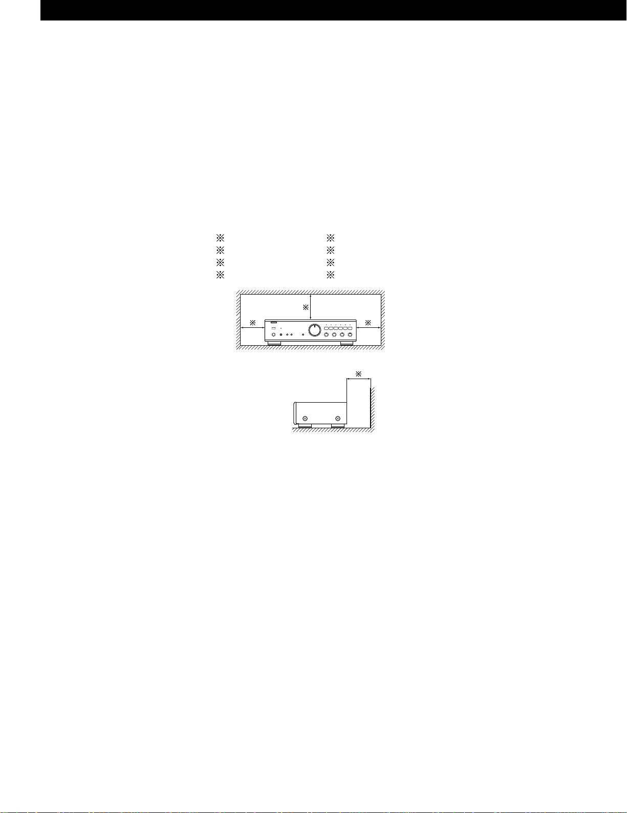
PRECAUTIONS FOR INSTALLATION
For heat dispersal, leave at least 10 cm of space between the top,
back and sides of this unit and the wall or other components.
SICHERHEITSMASSNAHMEN BEIM EINBAU
Lassen Sie zur Wärmeverteilung mindestens 10 cm Raum zwischen
der Oberseite, der Rückseite und den Seiten des Gerätes und der
Wand oder anderen Komponenten.
PRECAUTIONS D’INSTALLATION
Afin de disperser la chaleur, laisser un espace d’au moins 10 cm
entre le haut, l’arrière les côtés de cet appareil et le mur ou un autre
composant.
PRECAUZIONI PER L’INSTALLAZIONE
Per consentire una buona dispersione del calore, lasciate uno spazio
di almeno 10 cm tra le parti superiore, posteriore e laterali di
quest’unità e le parete o gli altri componenti.
PRECAUCIONES A TOMAR DURANTE LA INSTALACIÓN
Para que el calor se disipe, deje por lo menos 10 cm de espacio
entre las partes superior, posterior y laterales de esta unidad y la
pared u otros componentes.
VOORZORGSMAATREGELEN VOOR INSTALLATIE
Laat voor een goede warmteafvoer minstens 10 cm ruimte tussen
de boven-, achter- en zijkanten van dit toestel en de muur of andere
elementen.
OBSERVERA VID INSTALLATIONEN
För god värmeavledning, bör du lämna ett utrymme på minst 10 cm
ovanför, bakom och på sidorna av apparaten och väggen eller andra
komponenter.
PRECAUÇÕES DE INSTALAÇÃO
Para a dissipação do calor, deixar pelo menos 10 cm de espaço entre
o topo, a parte de trás e os lados desta unidade e a parede ou outros
componentes.
B
Wall
Wand
Mur
Parete
Pared
Muur
Vägg
Parede
10cm or more
10cm oder mehr
10cm ou plus
10cm o più
10cm o más
10cm of meer
10cm eller mer
10cm ou mais
Please check to make sure the following items are included
with the main unit in the carton:
(1) Operating Instructions ............................................................1
(2) Remote Control Unit (RC-176) ................................................1
(3) Batteries R6P (AA) ..................................................................2
(4) Service Station List .................................................................1
Bitte überprüfen Sie, ob die folgenden Teile vollständig in
der Verpackung enthalten sind:
(1) Bedienungsanleitung ..............................................................1
(2) Fernbedienung (RC-176) .........................................................1
(3) Batterien vom Typ R6P (AA) ...................................................2
(4) Servicestation-Liste.................................................................1
Veuillez contrôler que les articles suivants sont bien joints à
l’appareil principal dans le carton:
(1) Mode d’emploi........................................................................1
(2) Unité de télécommande (RC-176)...........................................1
(3) Piles R6P (AA) .........................................................................2
(4) Liste des stations techniques agréees ...................................1
Controllare che le parti seguenti si trovino imballate con
l’apparecchio nella scatola di spediziione:
(1) Istruzioni per l’uso...................................................................1
(2) Telecomando (RC-176)............................................................1
(3) Batterie R6P (AA) ....................................................................2
(4) Lista delle stazioni di servizio ..................................................1
Por favor verifique asegurandose de que los siguientes
artículos son empacados en la caja pero separados de la
unidad principal.
(1) Manual de instrucciones .........................................................1
(2) Unidad de control remoto (RC-176) ........................................1
(3) Pilas R6P (AA) .........................................................................2
(4) Lista de estaciones de servicio ...............................................1
Kontroleer of de volgende accessoires bij het hoofdtoestel in
de doos zijn verpakt:
(1) Gebruiksaanwijzing .................................................................1
(2) Afstandsbediening (RC-176) ...................................................1
(3) Batterijen R6P (AA) .................................................................2
(4) Lijst van service-centra ...........................................................1
Kontrollera att följande, förutom huvudapperaten, finns med
i kartongen:
(1) Bruksanvisning........................................................................1
(2) Fjärrkontroll (RC-176) ..............................................................1
(3) Batterier R6P (AA)...................................................................2
(4) Förteckning över service ställen .............................................1
Certifique-se de que as seguintes peças estão incluídas na
embalagem fora da unidade principal:
(1) Instruções de operação...........................................................1
(2) Unidade de controle remoto (RC-176) ....................................1
(3) Baterias R6P (AA)....................................................................2
(4) Lista das esações de reparação ..............................................1
3
ENGLISHDEUTSCHFRANCAISITALIANOESPAÑOLNEDERLANDSSVENSKAPORTUGUÊS
Page 4
4
NOTE:
1. Always keep the POWER switch on the main unit turned on.
2. Turn the power on and off from the remote control unit.
3. Unplug the power supply cord when you do not plan to use
the unit for a long period of time.
CAUTION:
If only the MUTE/STANDBY LED is lit, this means that the
power is turned off from the remote control unit. Turn the
power on from the remote control unit.
HINWEIS:
1. Lassen Sie den Netzschalter (POWER) am Hauptgerät stets
eingeschaltet.
2. Schalten Sie den Strom mit dem Fernbedienungsgerät einund aus.
3. Trennen Sie das Netzkabel vom Netz ab, wenn Sie
beabsichtigen, das Gerät über einen längeren Zeitraum
hinweg nicht zu benutzen.
VORSICHT:
Wenn nur das Stummschalt-/Bereitschafts-LED
(MUTE/STANDBY) leuchtet, so bedeutet dies, daß der Strom
vom Fernbedienungsgerät aus ausgeschaltet worden ist.
Schalten Sie den Strom vom Fernbedienungsgerät aus ein.
REMARQUE:
1. S’assurer que le commutateur d’alimentation (POWER) sur
l’unité principale soit toujours dans la position activée.
2. Allumer et éteigner l’appareil avec la télécommande.
3. Débrancher le cordon d’alimentation lorsque l’appareil ne sera
pas utilisé pendant une longue période.
ATTENTION:
Si seul le témoin (LED) de sourdine/veille (MUTE/STANDBY)
est allumé, cela signifie que l’appareil est mis hors circuit par
la télécommande. Allumer I’appareil avec la télécommande.
NOTA:
1. Tenete sempre l’interruttore della corrente (POWER) dell’unità
principale nella posizione di attivazione.
2. Accendete e spegnete la corrente usando il telecomando.
3. Scollegate il filo di alimentazione quando avete intenzione di
non usare l’apparecchio per un lungo periodo.
AVVERTIMENTO:
Se sono illuminati solo i LED di attenuazione/attesa
(MUTE/STANDBY), questo significa che la corrente e’ stata
spenta con il telecomando. Riaccendete la corrente usando il
telecomando.
NOTA:
1. Mantenga siempre activado el interruptor de alimentación
(POWER) en la unidad principal.
2. Encienda y apague el equipo desde la unidad de control
remoto.
3. Cuando la unidad vaya a estar fuera de uso por un período
prolongado de tiempo, desconecte el cable de alimentación.
PRECAUCION:
Cuando sólo el indicador LED de silenciamiento/modo de
espera (MUTE/STANDBY) esté encendido, significará que la
alimentación a la unidad ha sido desconectada desde la
unidad de control remote. Conecte la alimentación desde la
unidad de control remote.
OPMERKING:
1. Zorg er altijd voor dat de stroomschakelaar (POWER) van het
hoofdtoestel in de ingeschakelde stand staat.
2. Schakel de stroom in en uit m.b.v. de afstandsbediening.
3. Trek het netsnoer uit wanneer u denkt het toestel gedurende
een lange periode niet te gebruiken.
WAARSCHUWING:
Indien enkel de dempings-(MUTE)/STANDBY LED brandt,
betekent dit dat de spanning met de afstandsbediening is
uitgeschakeld. Schakel de spanning in met de
afstandsbediening.
OBSERVERA:
1. Låt alltid strömbrytaren (POWER) på huvudenheten vara
påslagen.
2. Slå till/från strömmen med hjälp av fjärrkontrollen.
3. Koppla loss nätkabeln om apparaten inte skall användas under
lång tid.
VARNING:
Om endast MUTE/STANDBY-lampan lyser betyder det att
strömmen har stängts av via fjärrkontrollen. Strömmen måste
då slås på via fjärrkontrollen igen.
NOTA:
1. Mantenha o interruptor da Corrente (POWER) na unidade
principal sempre ligado.
2. Ligue e desligue a corrente a partir da unidade de controlo
remoto.
3. Desconecte o fio de força quando intentar não utilizar a
unidade por longo tempo.
CAUTELA:
Se apenas se iluminar o LED de surdina/espera
(MUTE/STANDBY), isto significa que a força se desligou a
partir do controle remoto. Ligue a força a partir do controle
remoto.
ENGLISHDEUTSCHFRANCAISITALIANOESPAÑOLNEDERLANDSSVENSKAPORTUGUÊS
Page 5
5
NOTE ON USE / HINWEISE ZUM GEBRAUCH / OBSERVATIONS RELATIVES A L’UTILISATION /
NOTE SULL’USO / NOTAS SOBRE EL USO / ALVORENS TE GEBRUIKEN / OBSERVERA /
OBSERVAÇÕES QUANTO AO USO
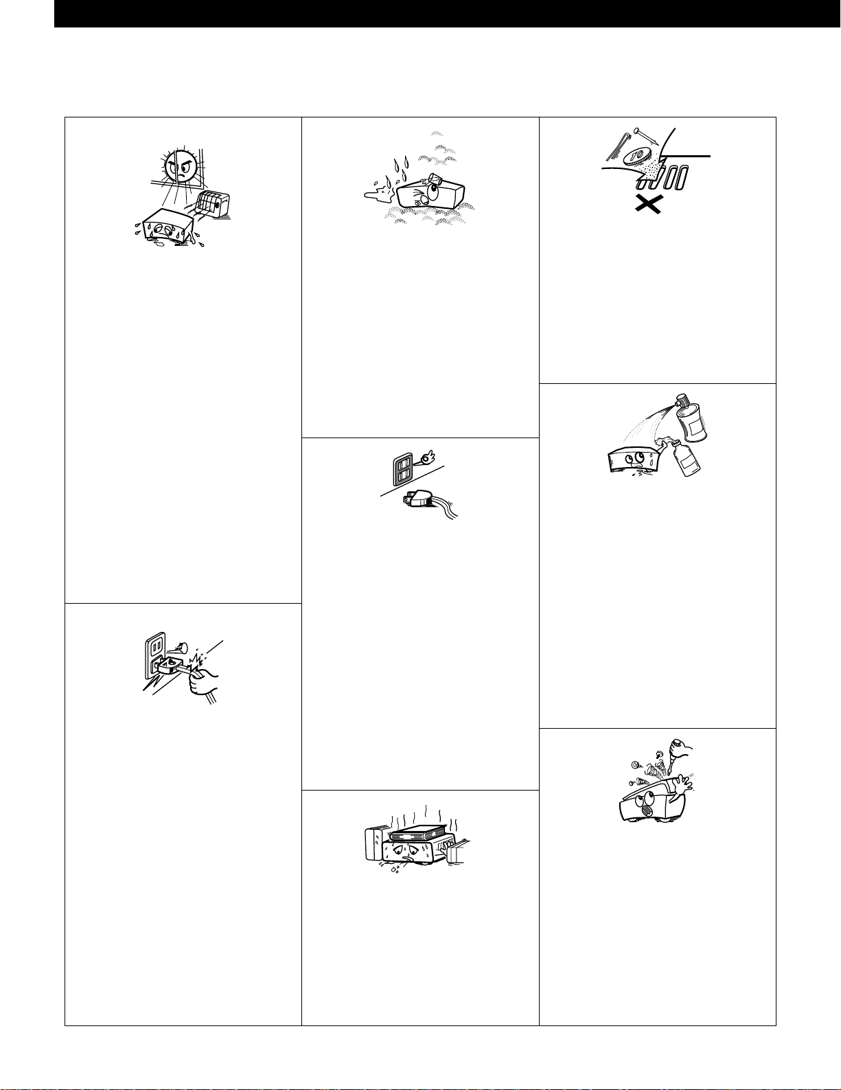
• Avoid high temperatures.
Allow for sufficient heat dispersion when
installed on a rack.
• Vermeiden Sie hohe Temperaturen.
Beachten Sie, daß eine ausreichend
Luftzirkulation gewährleistet wird, wenn das
Gerät auf ein Regal gestellt wird.
• Eviter des températures élevées
Tenir compte d’une dispersion de chaleur
suffisante lors de l’installation sur une étagère.
• Evitate di esporre l’unità a temperature alte.
Assicuratevi che ci sia un’adeguata dispersione
del calore quando installate l’unità in un mobile
per componenti audio.
• Evite altas temperaturas.
Permite la suficiente dispersión del calor
cuando está instalado en la consola.
• Vermijd hoge temperaturen.
Zorg voor een degelijk hitteafvoer indien het
apparaat op een rek wordt geplaatst.
• Undvik höga temperaturer.
Se till att det finns möjlighet till god
värmeavledning vid montering i ett rack.
• Evite temperaturas altas.
Conceda suficiente dispersão de calor quando
o equipamento for instalado numa prateleira.
• Keep the set free from moisture, water, and
dust.
• Halten Sie das Gerät von Feuchtigkeit, Wasser
und Staub fern.
• Protéger l’appareil contre l’humidité, l’eau et la
poussière.
• Tenete l’unità lontana dall’umidità, dall’acqua e
dalla polvere.
• Mantenga el equipo libre de humedad, agua y
polvo.
• Laat geen vochtigheid, water of stof in het
apparaat binnendringen.
• Utsätt inte apparaten för fukt, vatten och
damm.
• Mantenha o aparelho livre de qualquer
umidade, água ou poeira.
• Do not let foreign objects in the set.
• Keine fremden Gegenstände in das Gerät
kommen lassen.
• Ne pas laisser des objets étrangers dans
l’appareil.
• E’ importante che nessun oggetto è inserito
all’interno dell’unità.
• No deje objetos extraños dentro del equipo.
• Laat geen vreemde voorwerpen in dit apparaat
vallen.
• Se till att främmande föremål inte tränger in i
apparaten.
• Não deixe objetos estranhos no aparelho.
• Do not let insecticides, benzene, and thinner
come in contact with the set.
• Lassen Sie das Gerät nicht mit Insektiziden,
Benzin oder Verdünnungsmitteln in Berührung
kommen.
• Ne pas mettre en contact des insecticides, du
benzène et un diluant avec l’appareil.
• Assicuratevvi che l’unità non venga in contatto
con insetticidi, benzolo o solventi.
• No permita el contacto de insecticidas,
gasolina y diluyentes con el equipo.
• Laat geen insektenverdelgende middelen,
benzine of verfverdunner met dit apparaat in
kontakt komen.
• Se till att inte insektsmedel på spraybruk,
bensen och thinner kommer i kontakt med
apparatens hölje.
• Não permita que inseticidas, benzina e
dissolvente entrem em contacto com o
aparelho.
• Never disassemble or modify the set in any
way.
• Versuchen Sie niemals das Gerät auseinander
zu nehmen oder auf jegliche Art zu verändern.
• Ne jamais démonter ou modifier l’appareil
d’une manière ou d’une autre.
• Non smontate mai, nè modificate l’unità in
nessun modo.
• Nunca desarme o modifique el equipo de
ninguna manera.
• Nooit dit apparaat demonteren of op andere
wijze modifiëren.
• Ta inte isär apparaten och försök inte bygga om
den.
• Nunca desmonte ou modifique o aparelho de
alguma forma.
• Unplug the power cord when not using the set
for long periods of time.
• Wenn das Gerät eine längere Zeit nicht
verwendet werden soll, trennen Sie das
Netzkabel vom Netzstecker.
• Débrancher le cordon d’alimentation lorsque
l’appareil n’est pas utilisé pendant de longues
périodes.
• Disinnestate il filo di alimentazione quando
avete l’intenzione di non usare il filo di
alimentazione per un lungo periodo di tempo.
• Desconecte el cordón de energía cuando no
utilice el equipo por mucho tiempo.
• Neem altijd het netsnoer uit het stopkontakt
wanneer het apparaat gedurende een lange
periode niet wordt gebruikt.
• Koppla ur nätkabeln om apparaten inte kommer
att användas i lång tid.
• Desligue o fio condutor de força quando o
aparelho não tiver que ser usado por um longo
período.
• Do not obstruct the ventilation holes.
• Die Belüftungsöffnungen dürfen nicht verdeckt
werden.
• Ne pas obstruer les trous d’aération.
• Non coprite i fori di ventilazione.
• No obstruya los orificios de ventilación.
• De ventilatieopeningen mogen niet worden
beblokkeerd.
• Täpp inte till ventilationsöppningarna.
• Não obstrua os orifícios de ventilação.
• Handle the power cord carefully.
Hold the plug when unplugging the cord.
• Gehen Sie vorsichtig mit dem Netzkabel um.
Halten Sie das Kabel am Stecker, wenn Sie den
Stecker herausziehen.
• Manipuler le cordon d’alimentation avec
précaution.
Tenir la prise lors du débranchement du
cordon.
• Manneggiate il filo di alimentazione con cura.
Agite per la spina quando scollegate il cavo
dalla presa.
• Maneje el cordón de energía con cuidado.
Sostenga el enchufe cuando desconecte el
cordón de energía.
• Hanteer het netsnoer voorzichtig.
Houd het snoer bij de stekker vast wanneer
deze moet worden aan- of losgekoppeld.
• Hantera nätkabeln varsamt.
Håll i kabeln när den kopplas från el-uttaget.
• Manuseie com cuidado o fio condutor de
energia.
Segure a tomada ao desconectar o fio.
✽ (For sets with ventilation holes)
ENGLISHDEUTSCHFRANCAISITALIANOESPAÑOLNEDERLANDSSVENSKAPORTUGUÊS
Page 6
6
ENGLISH DEUTSCH FRANCAIS ITALIANO
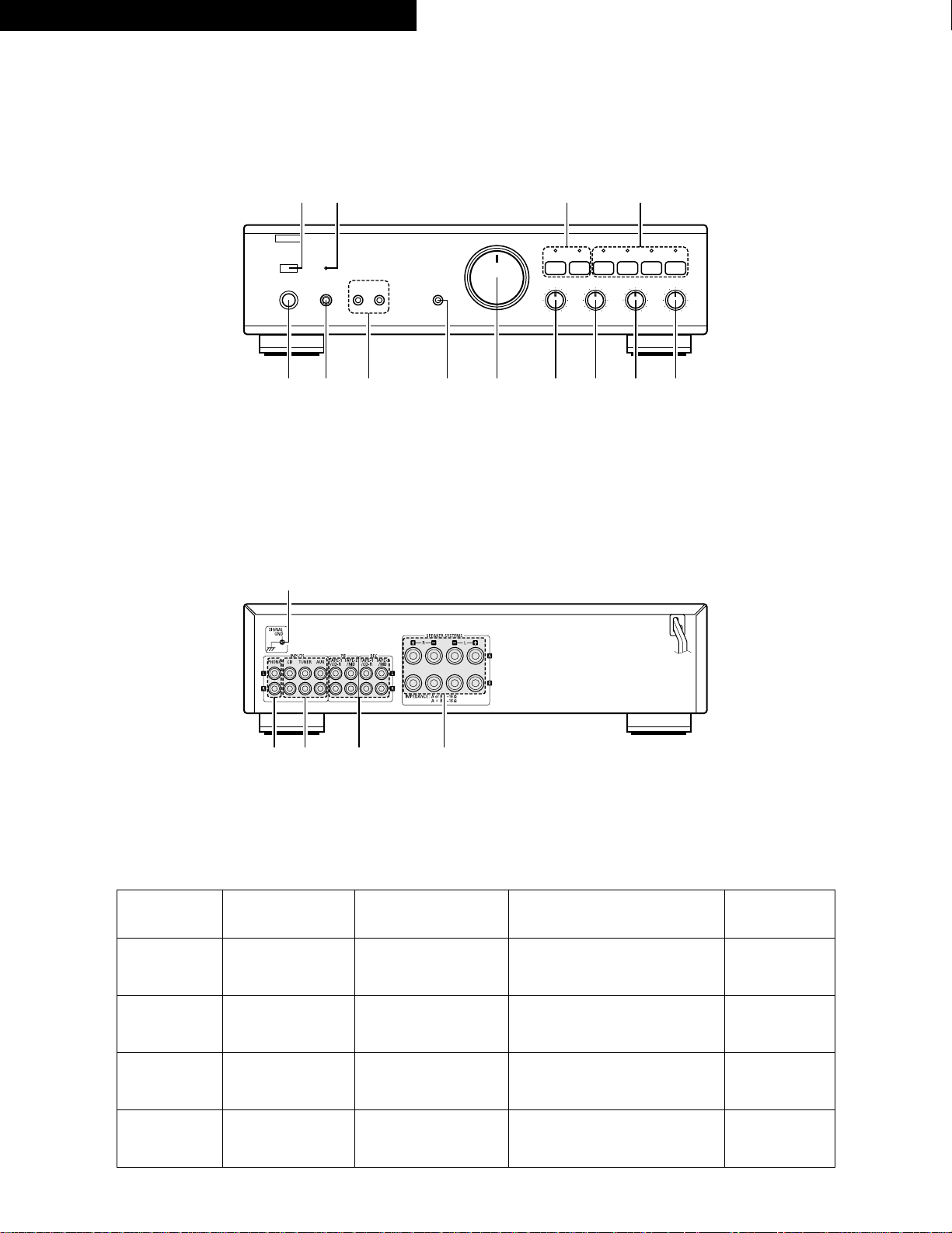
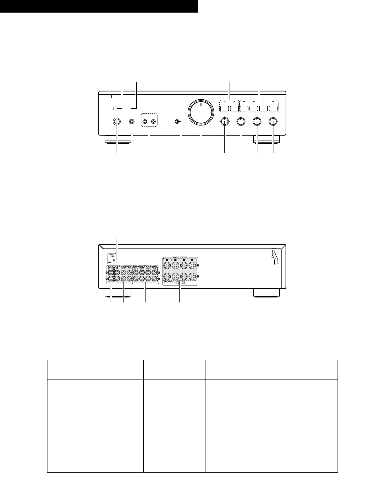
FRONT PANEL
FRONTPLATTE
PANNEAU AVANT
PANNELLO ANTERIORE
REAR PANEL
RÜCKWAND
PANNEAU ARRIERE
PANNELLO POSTERIORE
B
REMOTE SENSOR MUTE / STANDBY
VOLUME
SOURCE
DIRECT
£
¢
ON
OFF
POWER
¢£
ON / STANDBY OFF
INTEGRATED STEREO AMPLIFIER
£¢
ON OFF
PHONES SPEAKERS
AB
PMA-495R
TAPE-2 / MD
COPY
TAPE-1 / CD-R AUX TUNER CD PHONO
+–
+–
BALANCE BASS TREBLE
VARIABLE
LOUDNESS
LEFT
RIGHT
q w e r t y u i o
!0 !1 !2 !3
!5 !6 !7 !8
!4
!4 SIGNAL
GND
GND
GND
GND
GND
!5 PHONO
Phono Input Terminals
(Phono)
SchallplattenspielerEingangsbuchsen
(Phono)
Bornes d’entrée
(phono)
Terminali di ingresso
Phono
!6 CD, TUNER, AUX
Input Terminals
(CD, TUNER, AUX)
Eingangsbuchsen
(CD, TUNER, AUX)
Bornes d’entrée
(CD, TUNER, AUX)
Terminali di ingresso
(CD, TUNER, AUX)
!7 TAPE-1/CD-R, TAPE-2/MD
• TAPE PB • TAPE REC
Playback and Recording Terminals
• Playback Terminals
• Recording Terminals
Tonband-Ein/Ausgänge
• Wiedergabe
• Aufnahme
Bornes de lecture et d’enregistrement
• Bornes de lecture
• Bornes d’enregistrement
Terminali di riproduzione registrazione
• Terminali di riproduzione
• Terminali di registrazione
!8 SPEAKERS
Speaker Terminals
Lautsprecherklemmen
Bornes de hautparleurs
Terminali
degli altoparlanti
Fig. 1
Abb. 1
Page 7
7
ESPAÑOL NEDERLANDS SVENSKA PORTUGUÊS
PANEL FRONTAL
VOORPANEEL
FRAMSIDA
PAINEL FRONTAL
PANEL TRASERO
ACHTERPANEEL
BAKSIDA
PAINEL TRAZEIRO
B
REMOTE SENSOR MUTE / STANDBY
VOLUME
SOURCE
DIRECT
£
¢
ON
OFF
POWER
¢£
ON / STANDBY OFF
INTEGRATED STEREO AMPLIFIER
£¢
ON OFF
PHONES SPEAKERS
AB
PMA-495R
TAPE-2 / MD
COPY
TAPE-1 / CD-R AUX TUNER CD PHONO
+–
+–
BALANCE BASS TREBLE
VARIABLE
LOUDNESS
LEFT
RIGHT
q w e r t y u i o
!0 !1 !2 !3
!5 !6 !7 !8
!4
!4 SIGNAL
GND
GND
Terminal de toma
GND
Aarding
GND
GND
!5 PHONO
Terminales de entrada
de Phono
Draaitafelingangsaansluitpunten
Skivspelaringångar
Terminais de entrada
de fono (Fono)
!6 CD, TUNER, AUX
Terminales
de reprodución y grabación
(CD, TUNER, AUX)
Ingangsaansluitpunten
(CD, TUNER, AUX)
Ingångar
(CD, TUNER, AUX)
Terminais de entrada (disco
compacto, sintonizador,
auxílio) (CD, TUNER, AUX)
!7 TAPE-1/CD-R, TAPE-2/MD
• TAPE PB • TAPE REC
Terminales de reprodución y grabación
• Terminales de reprodución
• Terminales de grabación
Weergave- en opname-aansluitpunten
• Weergave-aansluitpunten
• Opname-aansluitpunten
Bandanslutningar
• Avspelningsanslutningar
• Inspelningsanslutningar
Terminais de reprodução e gravação
• Terminais de reprodução
• Terminais de gravação
!8 SPEAKERS
Terminales de
altavoces
Luidsprekeraansluitpunten
Högtalarkontakter
Terminais de
alto-falante
Fig. 1
Afb. 1
Page 8
8
ENGLISH DEUTSCH FRANCAIS ITALIANO
LINE IN (REC)
LINE IN
(REC)
LINE OUT
(PB)
LINE OUT
(PB)
LR LR
RLR
L
R
OUTPUTSINPUTS
LRL
R
L
R
L
R
OUTPUTSINPUTS
LRL
R
OUTPUT
L
R
L
R
OUTPUT
L
R
L
B
R
AUDIO OUTPUT
L
R
L
B
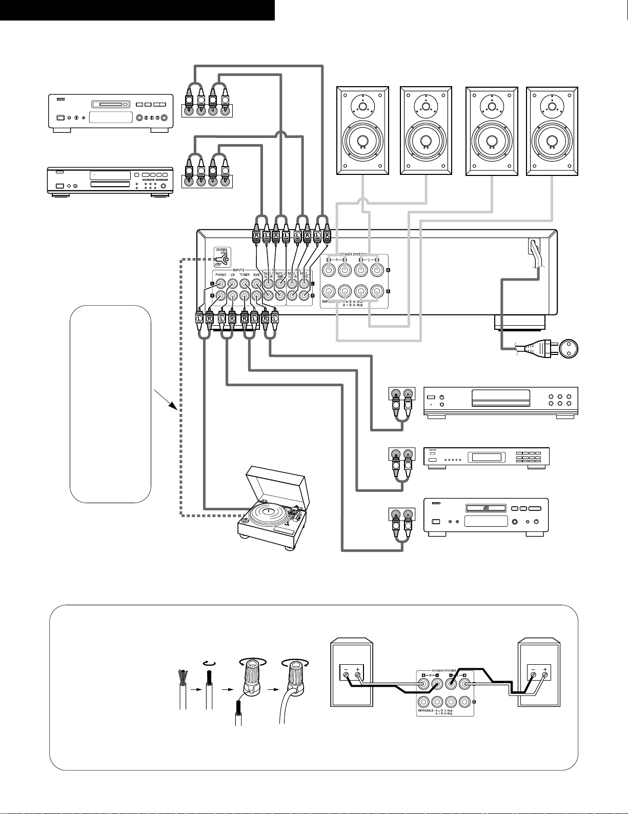
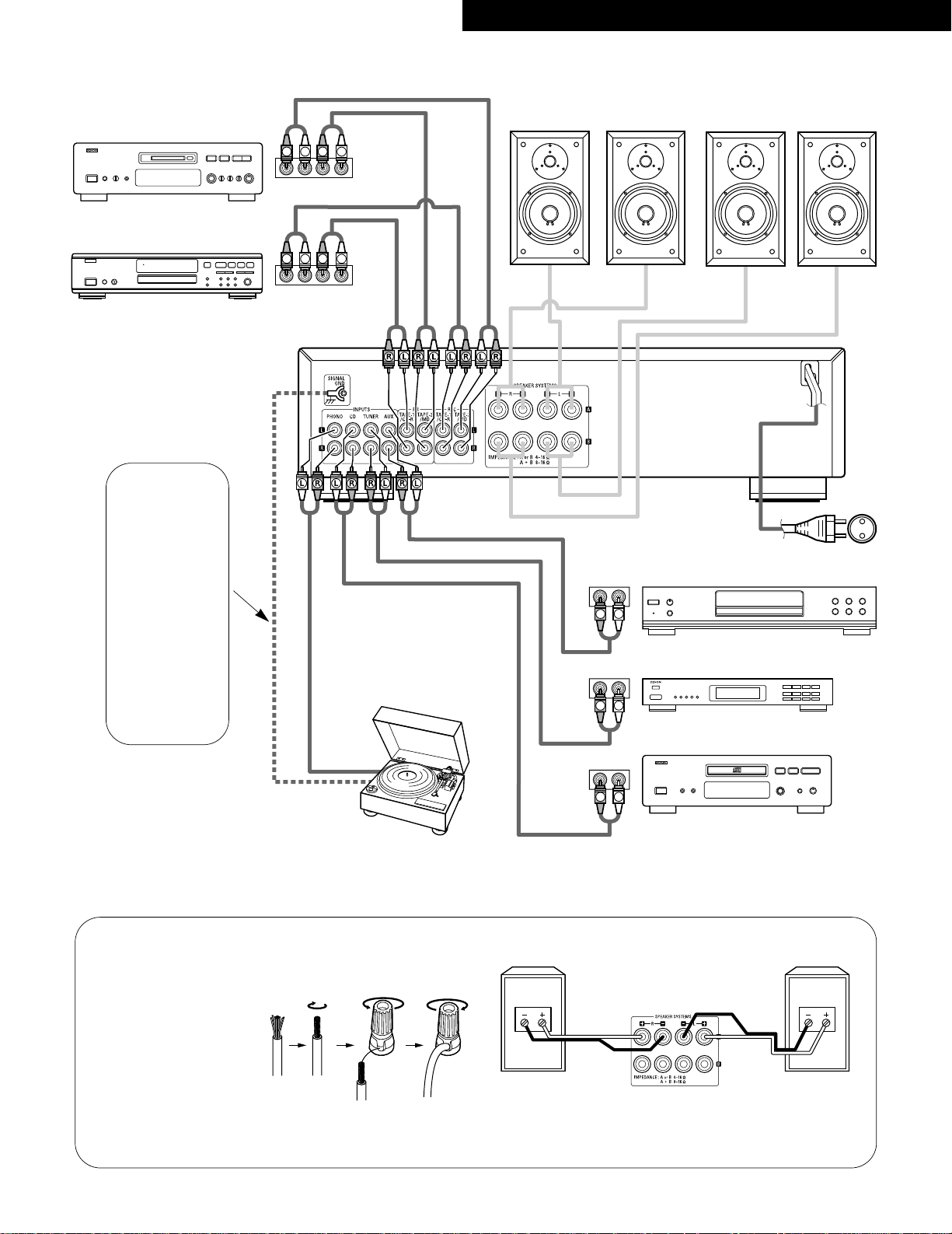
CONNECTIONS
ANSCHLÜSSE
CONNEXIONS
CONNESSIONI
Record Player (for MM)
Plattenspieler (für MM)
Tourne-Disque (pour MM)
Giradischi (per MM)
Speaker System (A)
Boxenpaar (A)
Système de Haut-Parleurs (A)
Sistema di altoparlanti (A)
Speaker System (B)
Boxenpaar (B)
Système de Haut-Parleurs (B)
Sistema di altoparlanti (B)
Erdungskabel
CD Player
CD-Spieler
Lecteur CD
Lettore CD
Tuner
Tuner
Tuner
Sintonizzatore
DVD player (sound only)
DVD-Spieler (nur Audio)
Lecteur DVD (son uniquement)
Lettore DVD (solo suono)
Tape deck or MD recorder
Cassetten-Deck oder MD-Rekorder
Platine cassette ou MD
Piastra del registratore o registratore MD
Tape deck or CD recorder
Cassetten-Deck oder CD-Rekorder
Platine cassette ou enregistreur de CD
Piastra del registratore o registratore CD
Power supply cord
Netzkabel
Cordon secteur
Cavo di alimentazione
Fig. 2
Abb. 2
Connection to the Speaker System
Anschluß der Lautsprecheranlage
Connexion du système de hautparleurs
Collegamento del sistema di altoparlanti
1. Peel off the sheathing from the end
of the cord.
2. Twist the wire strands.
3. Loosen the speaker terminal, insert
the wire lead portion of the code, and
then tighten the terminal.
1. Ein Stück der Isolierung am Kabelende
wegschneiden.
2. Den Litzendraht zusammendrehen.
3. Die Lautsprecherklemme lösen, das bloßliegende
Drahtende einführen und durch Anziehen der
Klemme gut einklemmen.
1. Dénuder la gaine de I’extrémité du cordon.
2. Torsader les fils de cordon.
3. Desserrer la borne du haut-parleur, insérer
l’extrémité du fil du cordon, puis serrer la borne.
1. Togliete la copertura dell’estremigà del cavo.
2. Attorcigliate i fili del cavo.
3. Allentate il terminale degli altoparlanti. Inserite
I’estremità del cavo e serrate quindi il terminale.
RIGHT SPEAKER
RECHTER LAUTSPRECHER
HAUT-PARLEUR DROIT
ALTOPARLANTE DESTRO
SPEAKER TERMINALS
LAUTSPRECHERBUCHSEN
BORNES DE HAUT-PARLEURS
TERMINALI DEGLI ALTOPARLANTI
LEFT SPEAKER
LINKER LAUTSPRECHER
HAUT-PARLEUR GAUCHE
ALTOPARLANTE SINISTRO
Fig. 3
Abb. 3
qw e
✽ Schließen Sie die
Erdungsleitung an.
Trennen Sie sie jedoch
wieder ab, wenn
Brummen oder andere
Geräusche auftreten.
✽ Collegate il filo di massa,
però scollegatelo se si
producono dei ronzii o
degli altri rumori.
Filo di massa a terra
Ground Wire
✽ Connect the ground wire,
but disconnect it if
humming or other noise
is generated.
Fil de Masse
✽ Connecter la prise de
terre mais la déconnecter
si cela provoque un
bourdonnement ou un
autre bruit.
Page 9
9
ESPAÑOLNEDERLANDSSVENSKAPORTUGUÊS
LINE IN (REC)
LINE IN
(REC)
LINE OUT
(PB)
LINE OUT
(PB)
LR LR
R
L
R
L
R
OUTPUTSINPUTS
LRL
R
L
R
L
R
OUTPUTSINPUTS
LRL
R
OUTPUT
L
R
L
R
OUTPUT
L
R
L
B
R
AUDIO OUTPUT
L
R
L
B
CONEXIONES
AANSLUITINGEN
ANSLUTNINGAR
CONEXÕES
Reproductor de discos (Para MM)
Platenspeler (Voor MM)
Skivspelare (För MM)
Toca-discos (Para MM)
Sistema de altavoces (A)
Luidsprekersysteem (A)
Högtalarsystem (A)
Sistema de alto-falante (A)
Sistema de altavoces (B)
Luidsprekersysteem (B)
Högtalarsystem (B)
Sistema de alto-falante (B)
Aarddraad
Reproductor CD
Kompakt diskspeler
CD-Spelare
Tocadora de discos compactos
Sintonizador
Tuner
Tuner
Sintonizador
Reproductor DVD (sólo sonido)
DVD-speler (alleen geluid)
DVD-Spelare (endast ljud)
Leitor DVD (apenas som)
Magnetófono de cassettes o grabador MD
Cassettedeck of MD-recorder
Kassettdäck eller MD-inspelare
Leitor de cassetes ou gravador MD
Magnetófono de cassettes o grabador CD
Cassettedeck of CD-recorder
Kassettdäck eller CD-inspelare
Leitor de cassetes ou gravador CD
Cable de alimentación
Netsnoer
Nätkabel
Cabo de alimentaçáo de corrente
Fig. 2
Afb. 2
Conexión al sistema de altavoces
Aansluiting op het luidsprekersysteem
Högtalaranslutning
Conexão ao sistema de alto-falante
1. Retire la aislación del extremo del
cable.
2. Retuerza los filamentos.
3. Afloje el terminal de altavoz, inserte la
porción de hilo de conductor y luego
apriete el terminal.
1. De isolatie van het uiteinde van het snoer
wegsnijden.
2. Draai de kerndraden ineen.
3. Maak het aansluitpunt van de luidspreker los, steek
het blootliggende uiteinde van de draad erin en
maak het aansluitpunt weer vast.
1. Skala av kabeländans isolering.
2. Tvinna kabelns kärntrådar.
3. Lossa högtalarkontakten, stick in den blottlagda
kabeländan och skruva fast kontakten.
1. Retire a proteção externa da extremidade do fio.
2. Torça os fios do condutor.
3. Desate o terminal do alto-falante, efetue a inserção da parte
do fio condutor do código, ajustando em seguida o terminal.
ALTAVOZ DERECHO
RECHTERLUIDSPREKER
HÖGER HÖGTALARE
ALTO-FALANTE DIREITO
TERMINALES DE ALTAVOCES
LUIDSPREKERAANSLUITPUNTEN
HÖGTALARKONTAKTER
TERMINAIS DE ALTO-FALANTE
ALTAVOZ IZQUIERDO
LINKERLUIDSPREKER
VANSTER HÖGTALARE
ALTO-FALANTE ESQUERDO
Fig. 3
Afb. 3
qw e
Fio-terra
✽ Sluit het aardingssnoer
aan, maar koppel het los
als bromruis of een ander
soort ruis wordt
opgewekt.
✽ Ligue o fio de massa,
mas desligue-o caso dê
origem a ruídos.
Conexión a masa
✽ Conecte el cable de
tierra, pero desconéctelo
si se produce zumbido o
algún otro ruido.
Jordkabel
✽ Anslut jordledningen,
men ta bort den om den
orsakar nätbrum
ellerandra störningar.
Page 10

10
ENGLISH
DESIGNATIONS AND FUNCTIONS OF PANEL CONTROLS
(Refer to page 6.)
q
POWER (Power Switch)
When the POWER switch is turned ON ( ¢ ), the
MUTE/STANDBY LED !1 lights.
When the power switch is turned ON, power is supplied to the
unit. It takes a few seconds after the power is turned on for the
unit to warm up. This is due to the built-in muting circuit that
eliminates noise during the on/off operation.
w
PHONES (Headphone Jack)
This jack is used to plug in the headphones.
e
SPEAKERS (Speaker Selection Switch)
The PMA-495R can be connected to two speaker systems:
speaker system A and speaker system B.
When A is pressed, the speaker system connected to speaker
output terminals A operates.
When B is pressed, the speaker system connected to speaker
output terminals B operates.
When A and B are pressed on together, both speaker systems
operate simultaneously. When the A and B switches are both
off (in the out position), there is no output from the speaker
terminals. This setting is used to listen to playback through the
headphones.
r
SOURCE DIRECT (Source Direct Switch)
The controls (BALANCE, VARIABLE LOUDNESS, and TONE)
can be used when this switch is in the OFF ( £ ) position.
When set to the ON ( ¢ ) position, the above controls are bypassed and the signals are input directly to the volume control
circuit, providing high quality sound.
t
VOLUME (Volume Control)
This knob controls the overall volume level.
Turn the knob to the right ( , ) to raise the volume and to the
left ( . ) to lower it.
y
BALANCE (Balance Control)
This knob is used to adjust the balance between the left and
right channels. When it is set to the center position, the
amplitude of the amplifier is equal on both sides. If there is a
difference in the left and right channel output voltages for a
cartridge, move the knob to the left and the right to adjust it. If
the volume on the right side is too low, turn the knob to the
right ( , ). If the volume on the left side is too low, turn the
knob to the left ( . ). This will achieve an even balance on the
left and right sides.
u
BASS (Bass Control)
This knob is used to control the bass quality of the sound.
When the knob is set at the center position, the frequency
characteristics are flattened in the range below 1000 Hz. The
bass is emphasized as the knob is moved off center to the right
( , ), and reduced as it is moved to the left ( . ).
i
TREBLE (Treble Control)
This knob is used to control the treble quality of the sound.
When the knob is set at the center position, the frequency
characteristics are flattened in the range above 1000 Hz. The
treble is emphasized as the knob is moved off center to the
right ( , ), and reduced as it is moved to the left ( . ).
o
VARIABLE LOUDNESS (Loudness Control)
At low volumes, the human ear is less sensitive to low (BASS)
and high (TREBLE) frequencies. Use this control to compensate
for this deficiency when listening at low volume levels. Turn
this control counter-clockwise until a natural balance of bass
and treble sound has been restored.
!0
REMOTE SENSOR (Remote Control Sensor)
This sensor receives the infra-red light transmitted from the
wireless remote control unit.
For remote control, point the wireless remote control unit
towards the sensor.
!1
MUTE/STANDBY LED
This LED flashes while the muting circuit is activated when the
power is turned on and when muting is turned on from the
remote control unit, and remains lit (without flashing) while the
power is on. In addition, this LED flashes rapidly when the
protection circuit is activated.
!2
TAPE SELECTOR (Tape Selector/Monitor Buttons)
• COPY/TAPE-1/CD-R:
Press this button once, COPY/TAPE-1/CD-R indicator will
light up and then you can play tape source on TAPE-1/CD-R
terminal. In this state you can copy COPY/TAPE-1/CD-R
source to TAPE-2/MD terminal.
Press again the button currently accessed, to play sources
selected by input selector !3, indicator goes out.
• TAPE-2/MD:
Press this button once, TAPE-2/MD indicator will light up and
then you can play tape or video source of TAPE-2/MD
terminal.
Press again the button currently accessed, to play sources
selected by input selector !3, indicator goes out.
!3
INPUT SELECTOR (Input Select Switch)
Use these to select the program source.
When the switch for the desired program source is selected, its
LED lights. One program source only can be selected at a time,
as follows:
• PHONO:
Use this position when using the record player connected to
the PHONO jacks. The record player should have an “MM”
cartridge.
• CD:
Use this position when using the CD player, etc., connected
to the CD jacks.
• TUNER:
Use this position when using the tuner, etc., connected to
the TUNER jacks.
• AUX:
Use this position when using the component connected to
the AUX jacks.
Page 11

11
ENGLISH
OPERATION
PREPARATION
1. CHECKING CONNECTIONS
• Make sure that all the connections are proper by referring to
the back panel. (Fig. 2~3)
• Check the polarity (positive and negative) of connections, and
the directivity of stereo separation (right cord to right channel
terminal, and left cord to left channel terminal).
• Check the directivity of pin cord connection.
2. SETTING OF EACH KNOB
• Turn the volume control knob t counterclockwise, to left.
• Set the rotary knob to “flat” or “center position”.
• Set SOURCE DIRECT r to “OFF ( £ )”.
• Press the TAPE MONITOR switch !2 to turn the LED off.
• Turn on the speaker selection switch for desired speaker
system (A or B).
After checking the above items, turn on the power, the amplifier is
set in the ready mode in a few seconds.
PLAYING A RECORD
1. Set the INPUT SELECTOR switch !3 to “PHONO”.
2. Operate the turntable and play the record.
3. Turn the volume and tone controls to yield an appropriate volume
and sound quality.
PLAYBACK OF CD PLAYER
1. Set the INPUT SELECTOR switch !3 to “CD”.
2. Operate the CD player.
3. Turn the volume and tone controls to yield an appropriate volume
and sound quality.
RECEPTION OF RADIO PROGRAMS
1. Set the INPUT SELECTOR switch !3 to “TUNER”.
2. Operate the tuner to receive a radio program.
3. Turn the volume and tone controls to yield an appropriate volume
and sound quality.
CONNECTIONS OF AUDIO EQUIPMENT TO AUX
TERMINALS
1. Set the INPUT SELECTOR switch !3 to “AUX” Position.
2. Operate the Audio equipment Systems.
3. Turn the volume and tone controls to yield an appropriate volume
and sound quality.
PLAYBACK WITH TAPE DECK
1. Set the TAPE MONITOR switch !2 to “COPY/TAPE-1/CD-R” or
“TAPE-2/MD”.
2. Operate the Tape Deck.
3. Turn the volume and tone controls to yield an appropriate volume
and sound quality.
RECORDING WITH TAPE DECK
The source to be recorded is selected by the INPUT SELECTOR
switch !3.
COPYING FROM ONE TAPE TO ANOTHER
To copy from COPY/TAPE-1/CD-R to TAPE-2/MD, press the
COPY/TAPE-1/CD-R switch !2.
MONITORING THE RECORDING
(If a 3-head tape deck is used, the sound being recorded can be
monitored during the recording.)
Use the TAPE MONITOR switches !2 to select the tape deck onto
which the sound is being recorded.
The LED for the selected tape deck lights.
CAUTION
Protective Circuit
This set is equipped with a high speed protective circuit. This
circuit protects the internal circuitry from damage due to large
currents flowing when the speaker jacks are not completely
connected or when an output is generated by a short circuit.
This protective circuit’s operation cuts off the output to the
speakers. In such a case, be sure to turn the power to the set
off and check the connections to the speakers. Then turn the
power on again. After muting for a few seconds, the set will
operate normally.
NOTE:
Copying is not possible from TAPE-2/MD to COPY/TAPE-1/CD-R.
Page 12
12
ENGLISH
REMOTE CONTROL OPERATION
The accessory Remote Control Unit is used to control the amplifier from a convenient distance.
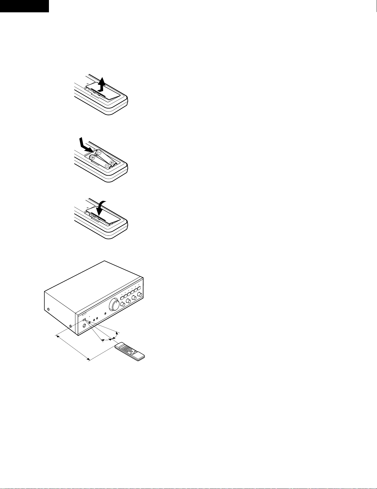
(1) Inserting the Dry Cell Batteries
1. Remove the battery cover on the Remote Control Unit.
Notes on Battery Usage
• RC-176 uses the size R6P (AA) dry cell batteries.
• The batteries will need to be replaced approximately once a year.
This will depend upon how often the Remote Control Unit is used.
• If, in less than a year from the time new batteries were inserted,
the Remote Control Unit falls to operate the Amplifier from a nearby position, it is time to replace the batteries.
(The included battery is only for verifying operation. Replace it
with a new battery as soon as possible.)
• Insert the batteries properly, following the polarity diagram inside
the battery compartment.
• Batteries are prone to damage and leakage. Therefore:
• Do not mix new batteries with used ones.
• Do not mix different types of batteries.
• Do not jumper opposite poles of the batteries, expose them to
heat, break them open, nor expose them to open fire.
• If the batteries have leaked, remove any traces of battery fluid
from the battery compartment wiping thoroughly with a dry cloth.
Then insert new batteries.
2. Insert two dry cell batteries as shown in the diagram on the
battery supply unit.
3. Replace the battery cover.
(2) Directions for use
B
• Operate the Remote Control Unit while pointing it towards the
Remote Control Sensor on the Amplifier as shown in the diagram
on the left.
• The Remote Control Unit can be used at distances up to about 8
meters in a straight line from the amplifier. This distance will
decrease if there are obstructions blocking the infra-red light
transmission or if the Remote Control Unit is not directed straight
at the amplifier.
Note on operation
• Do not press the operating buttons on the Amplifier and the Remote Control Unit at the same time. This will cause misoperation.
• Operation of the Remote Control Unit will become less effective or erratic if the infrared Remote Control Sensor on the Amplifier is exposed to
strong light or if there are obstructions between the Remote Control Unit and the sensor.
• In case you operate a VCR, TV or other components by remote control, do not operate buttons on two different remote control units at the
same time. This will cause misoperation.
Besides being able to operate the PMA-495R amplifier with this Remote Control Unit, you can also operate
a DENON cassette deck and CD player from this handy full-system Remote Control Unit.
Remote control section
Full-system Remote Control Unit
The full-system Remote Control Unit operates all major functions of the Amplifier, such as function switching, volume control. But that’s not
all! The same control pad can also control the major functions of a DENON CD player and cassette deck and tuner when combined with the
PMA-495R to create a remarkably ergonomic and versatile DENON system with all the quality sound reproduction that the devoted audiophile
expects.
Approx. 8 m
30°
30°
Page 13
13
ENGLISH
• The RC-176 Remote Control Unit can control CD players and cassette decks manufactured by DENON.
• Note that operation may not be possible for some models.
• Buttons are conveniently separated into groups, each group controlling one specific component. The groups are AMP, FUNCTION, CD, DECK
and TUNER etc..
CAUTION:
• If the power is turned off with the Remote Control Unit, the set is switched to the power stand-by state. If you are absent for a long
period of time, unplug the power cord.
• Only the MUTE/STANDBY LED !1 lights when in the power stand-by mode.
• You may experience erratic operation of the Remote Control Unit if it is operated in fluorescent light and direct sunlight, in particular if this
light strikes the Remote Control Sensor on the Amplifier. However, this is not a malfunction, and if this should happen, simply protect the
sensor against such light.
For details on operating other components, refer to the operating instructions for the CD player and/or cassette deck.
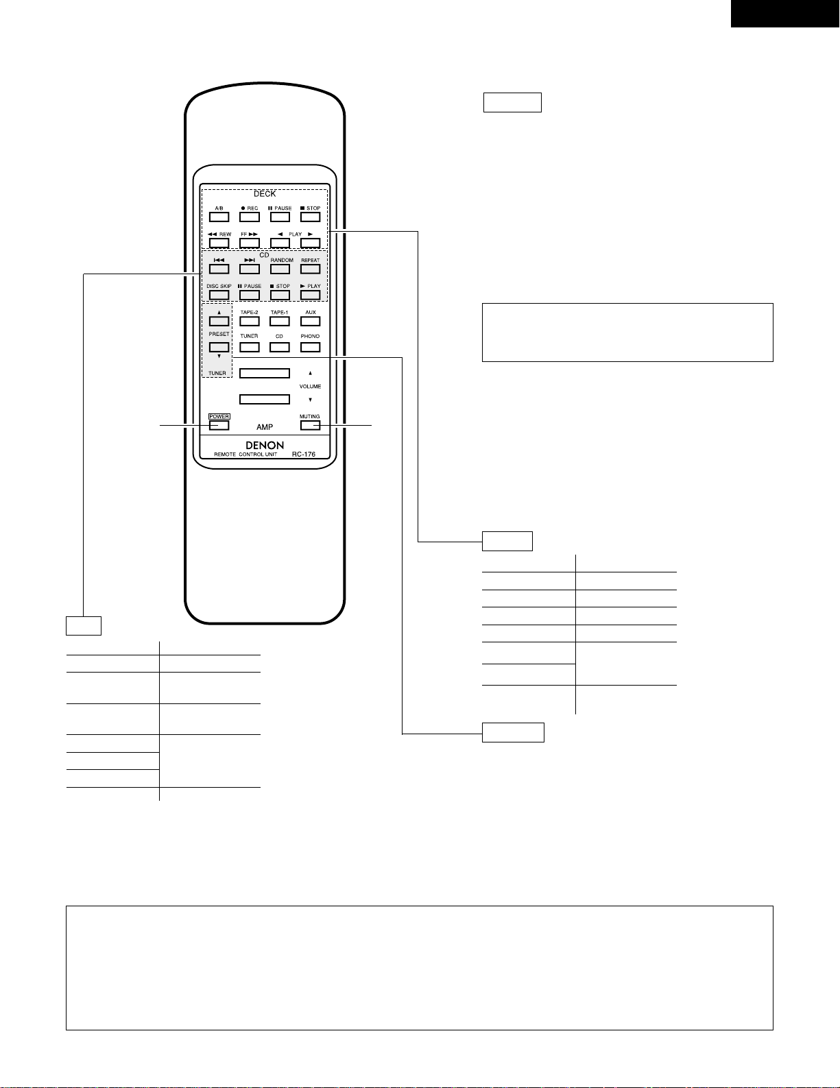
Remote Control Unit RC-176 supplied with the PMA-495R
q
button
• When the main unit’s POWER switch is set to the
ON/STANDBY position ( ¢ ), press this to turn the PMA495R’s power on and off.
• When the power is turned off from the remote control
unit, the main unit’s MUTE/STANDBY LED remains lit,
but the input LED turns off, indicating that the PMA-495R
is in the standby mode.
• When the main unit’s POWER switch is set to the OFF
position ( £ ) after turning the power off from the
remote control unit and then set back to the
ON/STANDBY position ( ¢ ), the PMA-495R is set to the
operating mode.
POWER
w
MUTING button
Pressing this switch will activate the muting condition and
no signals will be output to the speakers.
Other buttons
Other buttons are exclusively for the PMA-495R, and
function in the same way as the corresponding buttons on
the set.
This button will not function if there is a power
failure, if the power cord is not plugged in, or when
using an audio timer.
PLAY 1 PLAY button
0 PLAY (REV) PLAY (REV) button
2 STOP STOP button
6 REW REWIND button
FF 7 FF button
1 PLAY
PLAY button
2 STOP STOP button
8
Reverse Track
Search button
9
Forward Track
Search button
RANDOM
Refer to the
operating
instructions of your
DENON CD player
REPEAT
DISC SKIP
3 PAUSE PAUSE button
4 REC
3 PAUSE
A/B
Refer to the operating
instructions of your
DENON tape deck.
A/B DECK
SELECT button
Press this button to move up or down among the preset
station numbers.
•
ª
CD
DECK
TUNER
PRESET buttons
q w
Page 14

14
DEUTSCH
BEZEICHNUNGEN UND FUNKTIONEN DER BEDIENUNGSELEMENTE
(Beziehen Sie sich auf Seite 6.)
q
POWER (Netztaste)
Nach Drücken der Netztaste ( ¢ ) leuchtet die
Stummschalt/Bereitschafts-Anzeige (MUTE/STANDBY) !1 auf.
Der Verstärker wird durch Drücken dieser Taste eingeschaltet.
Nach dem Einschalten braucht das Gerät einige Sekunden, bis
es betriebsbereit ist, da hierbei der Stummschaltungskreis zur
Unterdrückung des normalerweise beim Einschalten einer
Stereoanlage auftretenden Knackgeräusches aktiviert wird.
w
PHONES (Kopfhörerbuchse)
Für den Anschluß von Stereo-Kopfhörern.
e
SPEAKERS (Lautsprecherwähler)
Der PMA-495R erlaubt den Anschluß zweier Lautsprecherboxenpaare.
Für Betrieb des an die A-Lautsprecherklemmen angeschlossenen Boxenpaars drücken Sie A bis zum Einrasten.
Für Betrieb des an die B-Lautsprecherklemmen angeschlossenen Boxenpaars drücken Sie B bis zum Einrasten.
Zum gleichzeitigen Betrieb beider Lautsprecheranlagen drücken
Sie A und B bis zum Einrasten. Zum Abschalten beider
Lautsprecheranlagen rasten Sie A und B aus, wodurch die
Signalabgabe an die Lautsprecherklemmen unterbrochen wird.
Diese Einstellung dient zum Hören über Kopfhörer.
r
SOURCE DIRECT (Direktquellenschalter)
Die Regler (BALANCE, VARIABLE LOUDNESS und TONE)
können benutzt werden, wenn dieser Schalter in der Position
OFF ( £ ) (AUS) steht.
Wenn der Schalter eingeschaltet (ON) ( ¢ ) ist, werden die
obigen Regler umgangen, und die Signale werden direkt zu
dem Lautstärkereglerkreis eingegeben, und ermöglichen damit
hohe Tonqualität.
t
VOLUME (Lautstärkeregler)
Mit diesem Regler wird die Gesamtlautstärke eingestellt.
Die Lautstärke wird durch Drehen des Reglers nach rechts ( , )
angehoben, durch Drehen nach links ( . ) vermindert.
y
BALANCE (Balanceregler)
Mit diesem Regler wird die Balance zwischen linkem und
rechtem Kanal eingestellt. In Mittelstellung ist die Verstärkung
für beide Kanäle gleich. Wenn der Tonabnehmer eine
unterschiedliche Ausgangs-spannung für linken und rechten
Kanal aufweist, kann die Abweichung durch Drehen dieses
Reglers ausgeglichen werden. Wenn die Lautstärke ds rechten
Kanals zu niedrig ist, muß der Regler nach rechts ( , ) gedreht
werden, bei zu niedrigen Lautstärke des linken Kanals nach
links ( . ). Hierdurch läßt sich die Balance zwischen linkem und
rechtem Kanal wieder herstellen.
u
BASS (Tiefenregler)
Mit diesem Regler läßt sich der Anteil der tiefen Frequenzen
einstellen. In Mittelstellung des Reglers ist der Frequenzgang
im Bereich unterhalb 1000 Hz linear, d.h. unmodifiziert. Die
Tiefen können durch Drehen des Reglers nach rechts ( , )
verstärkt, durch Drehen nach links ( . ) vermindert werden.
i
TREBLE (Höhenregler)
Mit diesem Regler läßt sich der Anteil der hohen Frequenzen
einstellen. In Mittelstellung des Reglers ist der Frequenzgang
im Bereich oberhalb 1000 Hz linear, d.h. unmodifiziert. Die
Höhen können durch Drehen des Reglers nach rechts ( , )
verstärkt, durch Drehen nach links ( . ) vermindert werden.
o
VARIABLE LOUDNESS
(Physiologischer Lautstärkeregler)
Bei niedriger Lautstärke ist das menschliche Gehör weniger für
niedrige (BASS) und hohe (TREBLE) Töne empfindlich.
Benutzen Sie den variablen Loudness-Regler, um den
unempfindlichen niedrigen Zuhörpegel auszugleichen. Drehen
Sie diesen Regler solange gegen den Uhrzeigersinn, bis die
natürliche Balance von Tiefen (BASS) und Höhen (TREBLE)
wieder hergestellt ist.
!0
REMOTE SENSOR (Fernbedienungssensor)
Dieser Sensor fängt die von der drahtlosen Fernbedienung
übermittelten infraroten Lichtstrahlen auf.
Soll eine Fernbedienung durchgeführt werden, ist die drahtlose
Fernbedienung direkt auf das Sensorfenster zu richten.
!1
MUTE/STANDBY LED
(Stummschalt-/Bereitschafts-LED)
Diese LED blinkt während der Aktivierungszeit der
Tonstummschaltung auf, wenn die Tonstummschaltung (nach
der Stromeinschaltung des Gerätes) zuvor mit der
Fernbedienung eingeschaltet wurde. Die Anzeige leuchtet
danach (ohne aufzublinken) auf, solange der Strom
eingeschaltet ist. Außerdem blinkt die LED schnell, wenn der
Schutzkreis aktiviert ist.
!2
BANDWÄHLER (Bandwahl-/Monitortasten)
• COPY/TAPE-1/CD-R:
Wenn Sie diese Taste einmal drücken, leuchtet die
COPY/TAPE-1/CD-R-Anzeige auf und Sie können die
Bandquelle wiedergeben, die an die TAPE-1/CD-R-Buchse
angeschlossen ist. In diesem Stadium können Sie die
COPY/TAPE-1/CD-R-Quelle auf die TAPE-2/MD-Buchse
überspielen.
Drücken Sie diese Taste noch einmal, um Tonquellen
wiederzugeben, die mit dem Eingangswähler !3 angewählt
worden sind; die Anzeige erlischt.
• TAPE-2/MD:
Wenn Sie diese Taste einmal drücken, leuchtet die TAPE2/MD-Anzeige auf und Sie können dann die Band- oder
Videoquelle wiedergeben, die an die Videoquelle der TAPE2/MD-Buchse angeschlossen ist.
Drücken Sie diese Taste noch einmal, um Tonquellen
wiederzugeben, die mit dem Eingangswähler
!3 angewählt
worden sind; die Anzeige erlischt.
!3
INPUT SELECTOR (Eingangswähler)
Wählen Sie hiermit die Programmquelle aus.
Wenn die Taste für die gewünschte Programmquelle ausgewählt
worden ist, leuchtet die LED. Es kann nur eine Programmquelle
zur Zeit ausgewählt werden – und zwar wie folgt:
• PHONO:
Wählen Sie diese Position, wenn Sie einen Plattenspieler
benutzen möchten, der an die PHONO-Buchsen
angeschlossen ist. Der Plattenspieler sollte mit einem
“MM”-Tonabnehmer ausgestattet sein.
Page 15

15
DEUTSCH
BEDIENUNGSANWEISUNGEN
VORBEREITUNG
1. DIE GERÄTEANSCHLÜSSE ÜBERPRÜFEN
• Vergewissern Sie sich, daß die Anschlüsse an der
Geräterückwand korrekt durchgeführt wurden. (Abb. 2~3)
• Prüfen Sie, ob die Lautsprecherboxen polrichtig (Minus an
Minus, Plus an Plus) und seitenrichtig (linke Box an linke
Klemmen, rechte Box an rechte Klemmen) angeschlossen sind.
• Prüfen Sie, ob die einzelnen Geräteverbindungen seitenrichtig
sind.
2. GRUNDEINSTELLUNGEN
• Drehen Sie den Lautstärkeregler t gegen den Uhrzeigersinn
nach links.
• Stellen Sie den Drehregler auf “tonlos” beziehungsweise die
Mittelstellung.
• Stellen Sie den Tonquellen Direktschalter (SOURCE DlRECT) r
auf “OFF ( £ )”.
• Drücken Sie den Band-Überwachungsschalter (TAPE
MONITOR) !2, um die LED auszuschalten (OFF).
• Den Lautsprecher-Wahlschalter dem gewünschten
Lautsprechersystem (A oder B) entsprechend einstellen.
Danach kann der Verstärker eingeschaltet werden. Einige Sekunden
später ist das Verstärker betriebsbereit.
SCHALLPLATTENWIEDERGABE
1. Stellen Sie den Eingangswahlschalter (INPUT SELECTOR) !3 auf
“PHONO”.
2. Spielen Sie eine Schallplatte ab.
3. Stellen Sie Lautstärke und Klang wunschgemäß ein.
CD-WIEDERGABE
1. Stellen Sie den Eingangswahlschalter (INPUT SELECTOR) !3 auf
“CD”.
2. Stellen Sie den CD-Spieler auf Wiedergabe.
3. Stellen Sie Lautstärke und Klang wunschgemäß ein.
RUNDFUNKEMPFANG
1. Stellen Sie den Eingangswahlschalter (INPUT SELECTOR) !3 auf
“TUNER”.
2. Stimmen Sie einen Sender ab.
3. Stellen Sie Lautstärke und Klang wunschgemäß ein.
WIEDERGABE MIT DEM AN DEN AUX-BUCHSEN
ANGESCHLOSSENEN GERÄT
1. Stellen Sie den Eingangswahlschalter (INPUT SELECTOR) !3 auf
“AUX”.
2. Stellen Sie das Gerät auf Wiedergabe.
3. Stellen Sie Lautstärke und Klang wunschgemäß ein.
HINWEIS:
Das Überspielen von TAPE-2/MD auf COPY/TAPE-1/CD-R ist
nicht möglich.
ÜBERWACHUNG DER AUFNAHME
(Wenn Sie ein 3-Kopf-Cassettendeck benutzen, kann der
aufgenommene Ton während der Aufnahme überwacht werden.)
Benutzen Sie die Band-Überwachungsschalter (TAPE MONITOR) !2,
um das Cassettendeck auszuwählen, auf das Sie aufnehmen
möchten.
Die LED des ausgewählten Cassettendecks leuchtet.
VORSICHT
Schutzschaltung
Diese Anlage ist mit einer Schnellauf-Schutzschaltung
ausgestattet. Diese Schaltung schützt die internen Schaltungen
der Anlage vor Schäden. Dies geschieht durch großen Stromfluß
bei nicht vollständig angeschlossenen Lautsprecherbuchsen
oder wenn ein Ausgang durch eine Ableitung erzeugt wird.
Gehen Sie in so einem Fall sicher, daß Sie das Netz der Anlage
ausschalten und überprüfen Sie die Anschlüsse der
Lautsprecher. Schalten Sie die Stromversorgung dann wieder
ein. Nach einer Stummschaltung von einigen Sekunden
funktioniert das Gerät wieder normal.
WIEDERGABE MIT DEM CASSETTENDECK
1. Stellen Sie den Bandmonitorschalter (TAPE MONITOR) !2 auf die
Position “COPY/TAPE-1/CD-R” oder “TAPE-2/MD”.
2. Bedienen Sie das Cassettendeck.
3. Stellen Sie die Lautstärke- und Klangregler so ein, daß Sie eine
passende Lautstärke und Klang erzielen.
AUFNAHME MIT DEM CASSETTENDECK
Die Tonquelle, die aufgenommen werden soll, wird mit dem
Eingangs-Wahlschalter (INPUT SELECTOR) !3 eingestellt.
ÜBERSPIELEN VON EINEM BAND AUF DAS ANDERE
Drücken Sie zum Überspielen von COPY/TAPE-1/CD-R auf TAPE2/MD, den Bandmonitorschalter COPY/TAPE-1/CD-R !2.
• CD:
Wählen Sie diese Position, wenn Sie einen CD-Spieler
benutzen möchten, der an die CD-Buchsen angeschlossen
ist.
• TUNER:
Wählen Sie diese Position, wenn Sie einen Tuner benutzen
möchten, der an die TUNER-Buchsen angeschlossen ist.
• AUX:
Wählen Sie diese Position, wenn Sie eine Komponente
benutzen möchten, die an die AUX-Buchsen angeschlossen
ist.
Page 16

16
DEUTSCH
FERNBEDIENUNG
Die als Sonderzubehör erhältliche Fernbedienung kann dazu benutzt werden, den Verstärker vom Sessel aus zu bedienen.
(1) Einlegen der Trockenbatterien
1. Nehmen Sie den Batteriedeckel der Fernbedienung ab.
Hinweise zum Gebrauch von Batterien
• Für die Fernbedienung RC-176 werden Trockenbatterien vom Typ
R6P (AA) benötigt.
• Die Batterien müssen nach etwa einem Jahr ausgewechselt
werden. Es hängt jedoch davon ab, wie oft und wie lange Sie Ihre
Fernbedienung anwenden.
• Kann der Verstärker nach einer kürzeren Zeit als einem Jahr nach
Batteriewechsel nicht mit der Fernbedienung bedient werden
(auch nicht aus nächster Distanz), ist es an der Zeit, die Batterien
auszuwechseln.
• Legen Sie die Batterien ordnungsgemäß ein und folgen Sie dabei
den Hinweisen im Batteriefach bezüglich der Polarität der
Batterien.
• Batterien können leicht beschädigt werden oder auslaufen.
Beachten Sie bitte deshalb:
• Verwenden Sie niemals neue Batterien zusammen mit alten.
• Legen Sie nur Batterien des gleichen Typs ein.
• Die Gegenpole der Batterien dürfen nicht überbrückt werden.
Die Batterien dürfen weder extremer Hitze oder einem offenen
Feuer ausgesetzt noch gewaltsam geöffnet werden.
• Sollten Batterien ausgelaufen sein, muß die ausgelaufene
Batterieflüssigkeit restlos aus dem Batteriefach mit einem
weichen Tuch entfernt werden. Danach können neue Batterien
eingelegt werden.
2. Legen Sie zwei Trockenbatterien wie im Batteriefach
angezeigt ein.
3. Legen Sie den Batteriedeckel wieder auf.
(2) Hinweise zur Anwendung der Fernbedienung
B
• Richten Sie die Fernbedienung direkt auf den Fernbedienungssensor des Verstärkers (wie in der linken Abbildung gezeigt) und
drücken Sie dann auf die entsprechende(n) Bedienungstaste(n).
• Die Fernbedienung kann innerhalb eines Radius von ungefähr 8
Meter zum Verstärker benutzt werden. Dieser Radius nimmt u.U.
ab, wenn die infraroten Lichtstrahlen von sich im Wege
befindlichen Gegenständen blockiert oder umgeleitet werden oder
wenn die Fernbedienung nicht direkt auf den Verstärker gerichtet
wird.
Hinweis zur Bedienung
• Drücken Sie die Bedienungstasten des Verstärkers und die der Fernbedienung nicht zur gleichen Zeit. Sie vermeiden damit das Auftreten von
Fehlfunktionen.
• Die Betrieb der Fernbedienung ist weniger effektiv bzw. irregulär, wenn der infrarote Fernbedienungs-Sensor des Verstärkers unter starker
Sonneneinstrahlung steht oder wenn sich zwischen Fernbedienung und Sensor größere Gegenstände befinden.
• Wenn Sie Ihren Videorekorder, Fernseher oder andere Komponenten ebenfalls mit einer Fernbedienung steuern, sollten die Bedienungstasten
zweier verschiedener Fernbedienungen nicht zur gleichen Zeit gedrückt werden. Sie vermeiden damit das Auftreten von Fehlfunktionen.
Neben der Steuerung des Verstärkers PMA-495R können Sie mit dieser handlichen Vollsystem-Fernbedienung auch
ein DENON-Cassettendeck bzw. einen DENON-CD-Spieler bedienen.
Fernbedienungsteil
Vollsystem-Fernbedienung
Diese Vollsystem-Fernbedienung steuert alle Hauptfunktionen des Verstärkers, wie z.B. Umschalten der Funktion, Regelung der Lautstärke.
Aber das ist noch nicht alles! Mit den gleichen Bedienungstasten – und kombiniert mit dem PMA-495R – können Sie auch die Hauptfunktionen
eines DENON-CD-Spielers bzw. DENON-Cassettendecks bzw. DENON-Tuners steuern. Beide Geräte zusammen bilden ein bemerkenswert
ergonomisches und vielseitiges DENON-Steuersystem, mit dem die qualitative Klangwiedergabe erreicht wird, die sich eingeschworene HiFiEnthusiasten wünschen und erwarten.
Ca. 8 m
30°
30°
Page 17

17
DEUTSCH
q
Netztaste
• Wenn der Netzschalter des Geräts in der Position
ON/STANDBY ( ¢ ) steht, wird die Stromversorgung des
PMA-495R durch Drücken dieser Taste ein- und
ausgeschaltet.
• Wenn das Gerät mit der Fernbedienung ausgeschaltet
wird, leuchtet die MUTE/STANDBY LED des Geräts auch
weiterhin, die Eingangs-LED erlischt jedoch. Dadurch
wird angezeigt, dass der PMA-495R im Stand-By-Modus
ist.
• Wenn der Netzschalter des Geräts in die Position OFF
( £ ) gestellt wird, nachdem das Gerät über die
Fernbedienung ausgeschaltet wurde, und anschließend
erneut in die Position ON/STANDBY ( ¢ ) gebracht wird,
befindet sich der PMA-495R im Betriebsmodus.
POWER
w
MUTING-Taste
Nach einem Druck auf diese Taste wird die
Stummabstimmung aktiviert und es erfolgt keine
Tonausgabe über die Lautsprecher.
Andere Tasten
Die andere Tasten sind ausschließlich für den PMA-495R
bestimmt und funktionieren wie die entsprechenden Tasten
an diesem Gerät.
Diese Taste ist nach einem Stromausfall, bei
abgezogenen Netzkabel und bei Anwendung eines
Audio-Timers außer Betrieb gesetzt.
PLAY 1 Abspieltaste
0 PLAY (REV)
Wiedergabe-/
Räcksuchlauftaste
2 STOP Stopptaste
6 REW Rückspultaste
FF 7 Schnell-Vorlauftaste
1 PLAY Abspieltaste
2 STOP Stopptaste
8
Taste für den automatischen
Suchlauf in Rückwärtsrichtung
9
Taste für den automatischen
Suchlauf in Vorwärtsrichtung
RANDOM
Beziehen Sie
sich auf die
Bedienungsanleitung für
Ihren DENON CD-Spieler
REPEAT
DISC SKIP
3 PAUSE Pausentaste
4 REC
3 PAUSE
A/B
Siehe in der
Bedienungsanleitung für
Cassettendeck von DENON
A/B Deck Wahltaste
Mit Hilfe dieser Taste können Sie in der Liste der
Speichernummern auf- und abblättern.
•
ª
CD-SPIELER (CD)
CASSETTENDECK (DECK)
TUNER
PRESET -Taste
• Das Fernbedienungsgerät RC-176 kann sowohl CD-Spieler als auch Cassettendecks, die von DENON hergestellt worden sind, steuern.
• Beachten Sie bitte, daß der Betrieb bei einige Modellen nicht möglich ist.
• Die Bedienungstasten sind in verschiedenen Gruppen zusammengefaßt, jede Gruppe steuert jeweils eine Komponente. Es gibt eine
Gruppeneinteilung für folgende Komponenten: AMP, FUNCTION, CD, DECK, TUNER usw..
VORSICHT:
• Wenn der Strom mit dem Fernbedienungsgerät ausgeschaltet worden ist, schaltet sich die Anlage in Strom-Betriebsbereitschaft. Wenn
Sie für längere Zeit abwesend sind, trennen Sie vorher das Netzkabel von der Netzsteckdose ab.
• Im Standby-Modus leuchtet nur die Stummschaltungs-/Standby-LED !1.
• Wenn die Fernbedienung unter fluoreszierenden Lichtverhältnissen oder bei Sonnenlichteinfall betätigt wird, kann es zu Situationen
kommen, unter denen die Fernbedienung nicht einwandfrei arbeiten kann. Das ist besonders dann der Fall, wenn ein solches Licht auf
den Fernbedienungs-Sensor des Verstärkers fällt. Es liegt dann keine Fehlfunktion vor. Es ist lediglich dafür zu sorgen, daß der Sensor
diesem Lichteinfall nicht weiter ausgesetzt wird.
Lesen Sie bezüglich von Einzelheiten bei der Bedienung in den Bedienungsanleitungen für den CD-Spieler und/oder des Cassettendecks nach.
Fernbedienung RC-176 und der mitgelieferte PMA-495R
q w
Page 18

18
FRANCAIS
NOMENCLATURE ET FONCTIONS DES COMMANDES DE PANNEAU
(Se reporter à la page 6.)
q
POWER (Interrupteur d’alimentation)
Lorsque l’interrupteur d’alimentation est pressé ( ¢ ), le
témoin de sourdine/attente (MUTE/STANDBY) !1 s’allume.
Lorsque l’interrupteur est pressé, l’appareil est mis sous
tension. Il faut quelques secondes à l’appareil pour chauffer
après la mise sous tension. Cela à cause du circuit de sourdine
incorporé pour éliminer le bruit lors de la mise sous/hors
tension.
w
PHONES (Prise de casque)
Cette prise sert à brancher le casque.
e
SPEAKERS
(Commutateur de sélection haut-parleurs)
Le PMA-495R peut se connecter à deux systèmes de hautparleurs: système A et système B.
Lorsque A est pressé, le système de haut-parleurs connecté à
la borne de sortie haut-parleurs A s’active.
Lorsque B est pressé, le système de haut-parleurs connecté à
la borne de sortie haut-parleurs B s’active.
Lorsque A et B sont pressés, les deux systèmes de hautparleurs fonctionnent simultanément. Lorsque les
commutateurs A et B sont tous les deux désactivés (position
haute), il n’y a pas de des bornes de haut-parleurs. Ce réglage
sert à l’écoute avec un casque d’écoute.
r
SOURCE DIRECT
(Commutateur de source directe)
Les commandes (BALANCE (équilibre), VARIABLE LOUDNESS
(compensation physiologique variable) et TONE (tonalité)
peuvent être utilisées lorsque ce commutateur est sur la
position OFF ( £ ).
Lorsqu’il est en position sous tension (ON) ( ¢ ), les
commandes ci-dessus sont en dérivation et les signaux entrent
directement dans le circuit de commande de volume,
fournissant un son de haute qualité.
t
VOLUME (Bouton de réglage de volume)
Ce bouton sert à ajuster le niveau sonore global.
Tourner ce bouton vers la droite ( , ) pour augmenter le
volume et vers la gauche ( . ) pour le réduire.
y
BALANCE (Réglage de l’équilibrage)
Ce bouton sert à régler la distribution du volume sonore entre
les canaux droit et gauche. S’il est réglé au centre, l’amplitude
de l’amplificateur est la même aux deux canaux. S’il semble y
avoir une différence de sortie des deux canaux pour une cellule,
effectuer l’ajustement en tournant le bouton vers la droite ou
vers la gauche. Si le volume du canal de droite est trop bas,
tourner le bouton vers la droite ( , ). Si celui de gauche est trop
bas, tourner le bouton vers la gauche ( . ). Cela établira
l’équilibrage des canaux droit et gauche.
u
BASS (Réglage de la tonalité grave)
Ce bouton sert au réglage de la qualité des sons graves.
Lorsqu’il est placé au centre, les caractéristiques de fréquences
sont aplanies sortie dans la gamme au-dessous de 1000 Hz.
Les sons graves sont accentués en tournant le bouton vers la
droite ( , ), et réduits en le tournant vers la gauche ( . ).
i
TREBLE (Réglage de la tonalité aiguë)
Ce bouton sert au réglage de la qualité des sons aigus. Lorsqu’il
est placé au centre, les caractéristiques de fréquences sont
aplanies dans la gamme au-dessus de 1000 Hz. Les sons aigus
sont accentués en tournant le bouton vers la droite ( , ), et
réduits en le tournant vers la gauche ( . ).
o
VARIABLE LOUDNESS
(Commande de compensation physiologique)
L’oreille humaine est moins sensible, lorsque le volume est
faible, aux basses (BASS) et hautes (TREBLE) fréquences.
Utiliser cette commande pour compenser cette déficience lors
d’une écoute à faible niveau de volume. Tourner cette
commande dans le sens des aiguilles d’une montre jusqu’à ce
qu’un équilibre naturel des sons graves et aigus soit obtenu.
!0
REMOTE SENSOR (Détecteur de télécommande)
Ce détecteur reçoit le rayon infrarouge émis par l’unité de
télécommande sans fil.
Pour une utilisation par télécommande, pointer l’unité de
télécommande sans fil vers le détecteur.
!1
MUTE/STANDBY LED
(Témoin de sourdine/attente)
Cet indicateur à LED clignote pendant l’activation du circuit de
sourdine lorsque l’appareil est mis sous tension et lorsque la
sourdine est activée depuis l’unité de télécommande et reste
allumé (sans clignoter) pendant que l’appareil est sous tension.
De plus, le voyant (LED) clignote rapidement lorsque le circuit
de protection est activé.
!2
SELECTEUR DE CASSETTE
(Touches de sélecteur de cassette/contrôle)
• COPY/TAPE-1/CD-R:
Appuyer sur cette touche une fois, l’indicateur COPY/TAPE1/CD-R s’allume et ensuite la source cassette peut être lue à
partir de la borne TAPE-1/CD-R. Dans cet état, la source
COPY/TAPE-1/CD-R peut être copiée à partir de la borne
TAPE-2/MD.
Appuyer à nouveau sur cette touche pour lire les sources
sélectionnées avec le sélecteur d’entrée
!3 l’indicateur
s’éteint.
• TAPE-2/MD:
Appuyer sur cette touche une fois, l’indicateur TAPE-2/MD
s’allume et ensuite la source cassette ou vidéo peut être lue
à partir de la borne TAPE-2/MD.
Appuyer à nouveau sur cette touche pour lire les sources
sélectionnées avec le sélecteur d’entrée
!3 l’indicateur
s’éteint.
!3
INPUT SELECTOR (Sélecteur d’entrée)
Utiliser ces sélecteurs pour sélectionner la source de
programme.
Lorsque la touche correspondant à la source de programme
désirée est sélectionnée, le témoin correspondant (LED)
s’allume. Une seule source de programme seulement peut être
sélectionnée à la fois de la manière suivante:
Page 19

19
FRANCAIS
INSTRUCTIONS D’UTILISATION
PREPARATION
1. CONTROLE DES CONNEXIONS
• S’assurer que toutes les connexions sont correctes en se
référant au panneau arrière. (Fig. 2~3)
• Vérifier les polarités (positive et négative) des connexions,
l’effet directif de la séparation stéréo (cordon droit à borne de
canal droit, cordon gauche à borne de canal gauche).
• Vérifier l’effet directif de la connexion du cordon à broches.
2. REGLAGE DES COMMANDES
• Tourner la commande de volume t dans le sens contraire des
aiguilles d’une montre, vers la gauche.
• Régler le bouton rotatif sur la position “réponse plate” ou
“centrale”.
• Régler SOURCE DIRECT r sur “OFF ( £ )”.
• Appuyer sur le commutateur de contrôle de bande (TAPE
MONITOR) !2 pour éteindre le témoin (LED).
• Mettre le commutateur de sélection d’enceinte correspondant
au système d’enceinte désiré (A ou B) sus tension.
Ces réglages terminés, mettre l’appareil sous tension, l’amplificateur
passant au mode prêt à fonctionner quelques secondes.
LECTURE D’UN DISQUE
1. Régler a commande INPUT SELECTOR !3 à “PHONO”.
2. Mettre le tourne-disque en marche et lire un disque.
3. Régler les commandes de volume sonore et de tonalité pour
obtenir le volume et la qualité sonores adéquats.
LECTURE D’UN LECTEUR CD
1. Régler la commande INPUT SELECTOR !3 à “CD”.
2. Mettre le lecteur CD en marche.
3. Régler les commandes de volume sonore et de tonalité pour
obtenir le volume et la qualité sonores adéquats.
RECEPTION DE PROGRAMMES RADIO
1. Régler la commande INPUT SELECTOR !3 à “TUNER”.
2. Régler le tuner pour la réception d’un programme radio.
3. Régler les commandes de volume sonore et de tonalité pour
obtenir le volume et la qualité sonores adéquats.
CONNEXIONS D’UN APPAREIL AUDIO AUX BORNES
AUX
1. Régler la commande INPUT SELECTOR !3 à “AUX”.
2. Mettre l’appareil audio en marche.
3. Régler les commandes de volume sonore et de tonalité pour
obtenir le volume et la qualité sonores adéquats.
REMARQUE:
La copie n’est pas possible de TAPE-2/MD vers COPY/TAPE1/CD-R.
CONTROLE DE L’ENREGISTREMENT
(Si une platine cassette à 3 têtes est utilisée, le son enregistré peut
être contrôlé pendant l’enregistrement.)
Utiliser les commutateurs de contrôle de bande (TAPE MONITOR) !2
pour sélectionner la platine cassette sur laquelle le son est
enregistré.
Le témoin (LED) correspondant à la platine cassette sélectionnée
s’allume.
ATTENTION
Circuit de protection
Cet appareil est pourvu d’un circuit de protection grande vitesse,
qui protège les circuits internes des dommages provoqués par
les courants électriques importants circulant quand les prises
des haut-parleurs ne sont pas correstement connectées ou en
cas de court-circuit. Ce circuit de protection coupe la puissance
passant aux haut-parleurs. Dans ce cas, couper l’alimentation de
l’appareil, et vérifier la connexion des haut-parleurs. Ensuite,
rallumer l’appareil. Après un silence de quelques secondes,
l’appareil fonctionne normalement.
LECTEUR AVEC UNE PLATINE CASSETTE
1. Régler le commutateur TAPE MONITOR (contrôle de bande) !2
sur “COPY/TAPE-1/CD-R” ou “TAPE-2/MD”.
2. Faire fonctionner la platine cassette.
3. Tourner les commandes de volume et de tonalité pour obtenir un
volume et qualité sonore appropriés.
ENREGISTREMENT AVEC UNE PLATINE CASSETTE
La source à enregistrer est sélectionnée par le sélecteur d’entrée
(INPUT SELECTOR) !3.
COPIE D’UNE CASSETTE VERS UNE AUTRE
Pour copier de COPY/TAPE-1/CD-R sur TAPE-2/MD, appuyer sur le
commutateur COPY/TAPE-1/CD-R !2.
• PHONO:
Utiliser cette position lors de l’utilisation de la platine-disque
connectée aux prises PHONO. La platine-disque doit avoir
une cellule à aimant mobile (MM).
• CD:
Utiliser cette position lors de l’utilisation d’un lecteur CD,
etc., connecté aux prises CD.
• TUNER:
Utiliser cette position lors de l’utilisation d’un tuner, etc.,
connecté aux prises TUNER.
• AUX:
Utiliser cette position lors de l’utilisation de l’appareil
connecté aux prises auxiliaires (AUX).
Page 20

20
FRANCAIS
UTILISATION DE LA TELECOMMANDE
L’unité de télécommande accessoire est utilisée pour piloter l’amplificateur à partir d’une distance pratique.
(1) Insertion des piles sèches
1. Enlever le couvercle du compartiment à piles de l’unité de
télécommande.
Remarques sur l’utilisation des piles
• La RC-176 utilise les piles sèches de format R6P (AA).
• Les piles doivent être remplacées approximativement une fois par
an. Cela dépend de la fréquence d’utilisation de l’unité de
télécommande.
• Si, moins d’un an après la mise en place de piles neuves, l’unité de
télécommande ne fait plus fonctionner le amplificateur depuis une
courte distance, il est temps de remplacer les piles.
• Insérer correctement les piles, en observant le schéma de polarité
à l’intérieur du compartiment à piles.
• Les piles sont susceptibles d’être endommagées et de fuir.
Il ne faut donc pas:
• Mélanger des piles neuves avec des piles déjà utilisées.
• Mélanger différents types de piles.
• Connecter des pôles opposés des piles, exposer celles-ci à la
chaleur, les ouvrir, les jeter dans le feu.
• Si les piles fuient, retirer toutes traces de liquide du compartiment
à piles en essuyant bien avec un chiffon sec. Puis insérer de
nouvelles piles.
2. Insérer deux piles sèches comme indiqué sur le schéma sur
le compartiment à piles.
3. Remettre en place le couvercle.
(2) Instructions d’utilisation
B
• Utiliser l’unité d télécommande en la pointant vers le détecteur de
télécommande sur l’amplificateur comme indiqué sur le schéma à
gauche.
• L’unité de télécommande peut être utilisée à des distances allant
jusqu’à environ 8 mètres en ligne droite depuis l’amplificateur.
Cette distance diminue s’il y a des obstructions bloquant la
transmission du rayon infrarouge ou si l’unité de télécommande
n’est pas dirigée directement vers l’amplificateur.
Remarque sur le fonctionnement
• Ne pas appuyer en même temps sur les touches de fonctionnement de l’amplificateur et de l’unité de télécommande. Cela provoquera un
fonctionnement défectueux.
• L’utilisation de l’unité de télécommande est moins efficace ou irrégulière si le détecteur de télécommande de l’amplificateur est exposé à un
fort éclairage ou s’il y a des obstructions entre l’unité de télécommande et le détecteur.
• En cas d’utilisation d’un magnétoscope, téléviseur ou autres appareils par télécommande, ne pas appuyer en même temps sur les touches de
deux unités de télécommande différentes. Cela provoquera un fonctionnement défectueux.
Outre la possibilité de faire fonctionner l’amplificateur PMA-495R avec cette unité de télécommande,
une platine cassette et un lecteur CD DENON peuvent également être utilisés depuis cette unité de
télécommande de système total pratique.
Section de télécommande
Unité de télécommande de système total
L’unité de télécommande de système total activé toutes les fonctions principales de l’amplificateur, comme la commutation de fonction, de
commande de volume. Mais ce n’est pas tout! La même unité peut aussi commander les principales fonction d’un lecteur CD et platine cassette
et tuner DENON lorsqu’ils sont combinés au PMA-495R pour créer un système DENON remarquablement ergonomique et polyvalent dont la
reproduction sonore a la qualité que les audiophiles attendent.
Environ 8 m
30°
30°
Page 21

21
FRANCAIS
• La télécommande RC-176 peut commander des lecteurs CD et platines cassettes DENON.
• Remarquer que cette opération ne peut pas être effectuée sur certains modèles.
• Les touches sont séparées en groupes, chaque groupe contrôlant un appareil spécifique. Les groupes sont: amplificateur (AMPL), de fonction
(FUNCTION), CD, magnétocassette (DECK) et TUNER etc..
ATTENTION:
• Si l’alimentation est coupée par la télécommande, l’appareil est mis en état de veille d’alimentation. En cas d’absence pendant une longue
période, débrancher le cordon d’alimentation.
• Seul le voyant de mise en sourdine/mise en attente (MUTE/STANDBY) !1 s’allume en mode d’attente d’alimentation.
• Le fonctionnement de l’unité de télécommande peut être irrégulier si elle est utilisée sous un éclairage fluorescent et les rayons directs
du soleil, en particulier si cette lumière frappe le détecteur de télécommande de l’amplificateur. Ce n’est cependant pas une panne de la
télécommande et si cela se produit, protéger simplement le détecteur de cette lumière.
Pour plus de détails concernant l’utilisation des autres appareils, se reporter aux modes d’emploi du lecteur CD et/ou magnétocassette.
Unité de télécommande RC-176 fournie avec le PMA-495R
q
Touche d’alimentation
• Lorsque l’interrupteur d’alimentation de l’unité principale
est en position ON/STANDBY ( ¢ ) (Marche/Veille),
appuyez sur cette touche pour mettre le PMA-495R sur
marche ou arrêt.
• Lorsque l’alimentation est coupée à partir de la
télécommande, les indicateur MUTE/STANDBY de l’unité
principale restent allumées mais celle d’entrée s’éteint,
indiquant que le PMA-495R est en mode veille.
• Lorsque l’interrupteur d’alimentation de l’unité principale
est sur arrêt (OFF) ( £ ) après avoir coupé l’alimentation
avec la télécommande et remis le bouton d’alimentation
sur la position ON/STANDBY ( ¢ ), le PMA-495R est
réglé en mode de fonctionnement.
POWER
w
Touche de sourdine MUTING
Lorsque cette touche est enfoncée, la sourdine est activée
et aucun signal n’est envoyé aux enceintes.
Autres touches
Les autres touches sont exclusivement pour le PMA-495R
et fonctionnent de la même manière que les touches
correspondantes de l’appareil.
Cette touche ne fonctionne pas s’il y a une panne de
courant, si le cordon d’alimentation n’est pas branché
ou lors de l’utilisation d’une minuterie audio.
PLAY 1 Touche de lecture (PLAY)
0 PLAY (REV)
Touche de lecture en sens inverse
(PLAY) (REV)
2 STOP Touche d’arrêt (STOP)
6 REW Touche de rembobinage (REWIND)
FF 7 Touche d’avance rapide (FF)
1 PLAY Touche de lecture (PLAY)
2 STOP Touche d’arrêt (STOP)
8
Touche de recherche
de plage en arrière
9
Touche de recherche
de plage en avant
RANDOM
Se reporter aux
instructions de
fonctionnement de votre
lecteur CD DENON
REPEAT
DISC SKIP
3 PAUSE Touche de PAUSE
4 REC
3 PAUSE
A/B
Se reporter au mode
d’emploi du magnéto-
cassette DENON.
Touche du sélecteur de
platine A/B (A/B DECK SELECT)
LECTEUR DE CD (CD)
MAGNETOCASETTE (DECK)
Appuyer sur cette touche pour faire défiler les numéros de
stations préréglées.
•
ª
SYNTONISEUR (TUNER)
Touche PRESET
q w
Page 22

22
ITALIANO
DESIGNAZIONE E FUNZIONAMENTO DEI CONTROLLI DEL PANNELLO
(Fate riferimento alla pagina 6.)
q
POWER (Interruttore di accensione)
Quando l’interruttore di alimentazione è acceso (ON) ( ¢ ),
l’indicatore di silenziamento/attesa (MUTE/STANDBY) !1 viene
illuminato.
Quando l’interruttore di accensione (POWER) viene premuto
nella posizione ON, l’unità viene alimentata di energia. Ci
vogliono pochi secondi dopo l’accensione dell’unità per
riscaldarla. Ciò dipende dal circuito incorporato di silenziatore
che elimina il rumore durante l’operazione di
accensione/spegnimento.
w
PHONES (presa per le cuffie)
Questa presa viene useta per inserire la spina delle cuffie.
e
SPEAKERS (interruttore di selezione di altoparlanti)
II PMA-495R può essere collegato a due sistemi di altoparlanti:
sistema A di altoparlanti oppure sistema B di altoparlanti.
Alla pressione di A, il sistema di altoparlanti collegato ai
terminali A di uscita opera.
Alla pressione di B, il sistema di altoparlanti collegato ai
terminali B di uscita opera.
Alla pressione contemporanea degli interruttori A e B, ambedue
i sistemi operano simultaneamente. Quando sia l’interruttore A
che quello B sono nella posizione spenta (quando gli interruttori
sono rialzati), non c’è nessun’uscita dai terminali degli
altoparlanti. Questa posizione viene usato per ascoltare
mediante le cuffie soltanto.
r
SOURCE DIRECT (Interruttore di sorgente diretta)
I controlli del bilanciamento (BALANCE), del loudness variabile
(VARIABLE LOUDNESS) e della tonalità (TONE) possono essere
usati quandi questo interruttore si trova nella posizione OFF
( £ ).
Quando lo stesso interruttore viene collocato nella posizione
attivata (ON) ( ¢ ), i controlli soprascritti vengono sorpassati e i
segnali sono trasmessi direttamente al circuito di controllo del
volume, provvedendo ad un’alta qualità sonora.
t
VOLUME (controllo del volume)
Questa manopola controlla il livello totale del volume.
Girate la manopola a destra ( , ) er aumentare il livello del
volume, e a sinistra ( . ) per diminuirlo.
y
BALANCE (controllo del bilanciamento)
Questa manopola viene usata per regolare il bilanciamento fra i
canali destro e sinistro. Quando viene collocata alla posizione
centrale, l’amplitudine dell’amplificatore è uguale per ambedue i
lati. In caso c’è una differenza nei voltaggi di uscita del canale
sinistro e quello destro per la cartuccia, girate la manopola a
destra ( , ). In caso il volume del lato sinistro è troppo basso,
girate la manopola a sinistra ( . ). Cosi otterrete un
bilanciamento buono dei lati sinistro e destro.
u
BASS (controllo dei bassi)
Questa manopola viene usata per controllare la qualità dei bassi
nel suono. Quando la manopola viene collocata nella posizione
centrale, le caratteristiche di frequenza nella gamma sotto i
1000 Hz vengono appiattite. I bassi vengono enfatizzati quando
la manopola viene spostata dal centro a destra ( , ), e vengono
diminuiti quando la manopola viene spostata a sinistra ( . ).
i
TREBLE (controllo degli acuti)
Questa manopola viene usata per controllare la qualità degli
acuti nel suono. Quando la manopola viene collocata nella
posizione centrale, le caratteristiche nella gamma sotto i 1000
Hz vengono appiattite. Gli acuti vengono enfatizzati quando la
manopola viene spostata dal centro a destra ( , ), e diminuiti
quando la manopola viene spostata a sinistra ( . ).
o
VARIABLE LOUDNESS (Controllo del loudness)
Ai livelli bassi di ascolto, l’orecchio umano è meno sensibile al
suono dei bassi (BASS) e degli acuti (TREBLE). Servitevi del
controllo del loudness per compensare l’insensibilità ai livelli
bassi di ascolto. Girate il controllo del loudness in senso
antiorario finchè non il bilanciamento naturale dei bassi (BASS)
e degli acuti (TREBLE) sia ottenuto.
!0
REMOTE SENSOR (Sensore a distanza)
Questo sensore riceve la luce infrarossa trasmessa dal
telecomando senza fili.
Per manovrare l’unità a distanza, puntate il telecomando senza
fili verso questo sensore.
!1
MUTE/STANDBY LED (LED di silenziamento/attesa)
Questi LED lampeggeranno all’attivazione del circuito di
silenziamento quando accendete la corrente oppure quando
viene attivato il silenziamento con il telecomando. I LED
rimarranno illuminati (senza lampeggiare) finchè rimane accesa
la corrente. Inoltre, il LED lampeggia velocemente quando il
circuito di protezione è stato attivato.
!2
SELETTORE DEL NASTRO
(Tasti di selezione/monitoraggio del nastro)
• COPY/TAPE-1/CD-R:
Premete questo tasto una volta. L’indicatore COPY/TAPE1/CD-R si illumina e potete riprodurre il nastro usando il
terminale TAPE-1/CD-R.
In questo stato potete copiare la fonte COPY/TAPE-1/CD-R al
terminale TAPE-2/MD.
Premete il tasto nuovamente per riprodurre le fonti
selezionate con il selettore dell’entrata !3, l’indicatore si
spegnerà.
• TAPE-2/MD:
Premete questo tasto una volta. L’indicatore TAPE-2/MD si
illuminerà e sarà possibile riprodurre nastri o videocassette
usando il terminale TAPE-2/MD.
Premete il tasto nuovamente per riprodurre le fonti
selezionate con il selettore dell’entrata !3, l’indicatore si
spegnerà.
!3
INPUT SELECTOR
(Interruttore di selezione dell’ingresso)
Usate questo interruttore per selezionare la sorgente del
programma.
Alla pressione del tasto che corrisponde alla sorgente
desiderata, il LED del tasto si illuminerà. Potete selezionare
soltanto un programma per volta, come segue:
• PHONO:
Usate questa posizione per adoperare il giradischi che è stato
collegato alle prese per il giradischi (PHONO). Il giradischi
deve essere dotato di una cartuccia del tipo a magnete
mobile (MM).
Page 23

23
ITALIANO
INSTRUZIONI PER L’OPERAZIONE
PREPARAZIONE
1. CONTROLLO DEI COLLEGAMENTI
• Accertatevi che tutti i collegamenti sono corretti facendo
riferimento al pannello posteriore. (Fig. 2~3)
• Controllate la polariga (positiva e negativa) dei collegamenti, e la
direttività della separazione stereo (il filo destro al terminale del
canale destro, e il filo sinistro al terminale del canale sinistro).
• Controllate la direttività del collegamento dei perni dei fili.
2. POSIZIONE DI OGNI MANOPOLA
• Girate la manopola di controllo del volume t nel senso
antiorario, verso sinistra.
• Collocate la manopola rotante nella posizione della “risposta
piatta” o nella “posizione centrale”.
• Collocate l’interruttore di fonte diretta (SOURCE DIRECT) r
nella posizione “OFF ( £ )”.
• Premete l’interruttore di monitoraggio del nastro (TAPE
MONITOR) !2 affinchè si spenga il LED.
• Attivate l’interruttore di selezione dell’altoparlante per il sistema
desiderato degli altoparlanti (A o B).
Dopo aver controllato i punti soprascritti, accendete la corrente e
l’amplificatore viene messo nel modo di attesa in pochi secondi.
RIPRODUZIONE DI UN DISCO
1. Collocate il INPUT SELECTOR (selettore di segnale di ingresso)
!3 alla posizione “PHONO”.
2. Adoperate il giradischi e riproducete il disco.
3. Regolate i controlli del volume e del tono per ottenere il livello di
volume e la qualità sonora che desiderate.
RIPRODUZIONE DI UN LETTORE DI COMPACT DISC
1. Collocate l’interruttore INPUT SELECTOR (selettore di segnale di
ingresso)
!3 alla posizione “CD”.
2. Adoperate il lettore di Compaci Disc.
3. Regolate i controlli del volume e del tono per ottenere il livello di
volume e la qualità sonora che desiderate.
RICEZIONE DI PROGRAMMI RADIO
1. Collocate l’interruttore INPUT SELECTOR (selettore di segnale di
ingresso)
!3 alla posizione “TUNER”.
2. Adoperate il sintonizzatore per ricevere un programma radio.
3. Regolate i controlli del volume e del tono per ottenere il livello di
volume e la qualità sonora che desiderate.
NOTA:
Non sarà possibile effettuare una duplicazione da TAPE-2/MD a
COPY/TAPE-1/CD-R.
MONITORAGGIO DELLA REGISTRAZIONE
(Nel caso in cui usate una piastra a cassette dotata di 3 testine,
potete effettuare un monitoraggio del suono in fase di registrazione.)
Usate gli interruttori di monitoraggio del nastro (TAPE MONITOR) !2
per selezionare la piastra a cassetta su cui viene registrata la musica.
Il LED della piastra selezionata si illuminerà.
AVVERTIMENTO
Circuito di protezione
Quest’unità è dotata di un circuito di protezione ad alta velocità.
Questo circuito serve per proteggere i circuiti interni contro i
danni che potrebbero accadere per via dei larghi flussi di
corrente a cui vengono esposti quando le prese degli altoparlanti
non sono completamente collegate o quando un’uscita viene
alimentata via un cortocircuito. L’operazione di questo circuito di
protezione fà sì che l’uscita agli altoparlanti viene bloccata. In tal
caso, accertatevi di spegnere l’unità e di controllare i
collegamenti degli altoparlanti. Poi riaccendere la corrente. Dopo
un silenziamento di pochi secondi, l’unità funzionerà
normalmente.
COLLEGAMENTO DI COMPONENTI AUDIO Al TERMINALI
AUX
1. Collocate l’interruttore INPUT SELECTOR (selettore di segnale di
ingresso) !3 alla posizione “AUX”.
2. Adoperate il sistema del componente audio.
3. Regolate i controlli del volume e del tono per ottenere il livello di
volume e la qualità sonora che desiderate.
RIPRODUZIONE USANDO LA PIASTRA A CASSETTE
1. Collocate l’interruttore di monitoraggio del nastro (TAPE
MONITOR) !2 in una delle posizioni “COPY/TAPE-1/CD-R” o
“TAPE-2/MD”.
2. Attivate la piastra a cassette.
3. Girate i controlli del volume e della tonalità per ottenere un effetto
adeguato del volume e della qualità sonora.
REGISTRAZIONE USANDO LA PIASTRA A CASSETTE
Selezionate la sorgente da registrare usando l’interruttore di
selezione dell’ingresso (INPUT SELECTOR) !3.
DUPLICAZIONE DA UN NASTRO AD UN ALTRO NASTRO
Per copiare da COPY/TAPE-1/CD-R a TAPE-2/MD, premete il
l’interruttore COPY/TAPE-1/CD-R !2.
• CD:
Usate questa posizione per adoperare il lettore CD ecc. che è
stato collegato alle prese CD.
• TUNER:
Usate questa posizione per adoperare il sintonizzatore ecc.
che è stato collegato alle prese per il sintonizzatore (TUNER)
• AUX:
Usate questa posizione per adoperare il componente che è
stato collegato alle prese ausiliario (AUX).
Page 24

24
ITALIANO
FUNZIONAMENTO DEL TELECOMANDO
II telecomando accessorio viene usato per manovrare l’amplificatore ad una distanza molto comoda.
(1) Installazione delle batterie a secco
1. Rimuovete il coperchio del vano batterie sul telecomando.
Note sull’uso delle batterie
• II telecomando RC-176 viene usato con delle batterie a secco della
misura R6P (AA).
• Le batterie vengono sostituite circa una volta all’anno.
Comunque, questo intervallo dipende dall’uso del telecomando.
• Se fosse impossibile manovrare l’amplificatore usando il
telecomando da vicino, significa che bisogna sostituire le batterie,
anche se non sia passato un anno dall’ultima sostituzione delle
batterie.
• Installate le batterie correttamente, rispettando l’illustrazione delle
polarità all’interno del vano batterie.
• Le batterie sono soggette a danni e perdite.
Perciò seguite i seguenti consigli:
• Non mischiate nuove batterie con delle vecchie batterie.
• Non mischiate vari tipi di batterie.
• Non installate le batterie con le polarità opposte.
Non esponete le batterie al calore, né apritele, né gettatele sul
fuoco.
• Qualora le batterie perdessero, rimuovete ogni traccia di liquido
delle batterie dal vano batterie strofinando il vano attentamente
con un panno morbido. Quindi inserite delle nuove batterie.
2. Inserite due batterie a secco seguendo l’illustrazione del vano
stesso.
3. Rimettete il coperchio del vano batterie.
(2) Istruzioni d’uso
B
• Usate il telecomando puntandolo verso il sensore a distanza del
amplificatore secondo l’illustrazione qui destra.
• Il telecomando può essere usato ad una distanza di massimo 8
metri davanti all’amplificatore. Questa distanza diminuirà qualora ci
fossero degli ostacoli a bloccare il raggio di trasmissione oppure se
il telecomando non puntasse direttamente verso l’amplificatore.
Note sul funzionamento
• Non premete contemporaneamente i tasti operativi dell’amplificatore e del telecomando, altrimenti si verificheranno delle malfunzioni.
• II funzionamento del telecomando diventerà meno efficiente o scorretto se il sensore a raggi infrarossi sull’amplificatore venisse esposto ad
una luce forte oppure se ci sono degli ostacoli tra il telecomando e il sensore.
• Nel caso in cui manovrate un videoregistratore, un televisore o un altro componente con un telecomando, non premete i tasti su due
telecomandi differenti contemporaneamente, altrimenti si verificheranno delle malfunzioni.
A parte il fatto che potete usare questo telecomando per manovrare l’amplificatore PMA-495R,
potete anche manovrare una piastra a cassette e un lettore CD della DENON con questo
telecomando comodo dal funzionamento completo.
Sezione del telecomando
Telecomando dal funzionamento completo
Questo telecomando dal funzionamento completo serve per manovrare tutte le funzioni principali dell’amplificatore, quale la commutazione
della funzione, il controllo del volume. Ma ciò non è tutto! La stessa tastiera può anche controllare le funzioni principali di un lettore CD, di una
piastra a cassette e di un sintonizzatore della marca DENON quando si combinano questi componenti con il PMA-495R per creare un sistema
DENON eccezionalmente ergonomica e versatile con la riproduzione sonora ad alta qualità che è essenziale per ogni audiofilo esigente.
Circa 8 m
30°
30°
Page 25

25
ITALIANO
• II telecomando RC-176 può controllare i lettori CD e le piastre a cassette della DENON.
• Osservate che l’operazione potrebbe non essere disponibile per alcuni modelli.
• I tasti sono stati comodamente separati in gruppi e ciascun gruppo controlla un componente specifico. I gruppi sono AMP, FUNCTION CD,
DECK e TUNER, ecc..
AVVERTIMENTO:
• Se si spegne la corrente usando il telecomando, l’apparecchio entra nel modo di attesa accensione. Scollegate il filo di alimentazione se
avete intenzione di non usare l’apparecchio per un lungo periodo.
• Quando l’unità si trova nel modo di attesa, si accende solamente il LED MUTE/STANDBY !1.
• Si potrebbero verificare delle anormalità nel telecomando se viene usato sotto una luce fluorescente oppure nella luce diretta del sole,
specialmente se questa luce arriva al sensore a distanza dell’amplificatore. Comunque, questo non è segno di malfunzione e se
accadesse, proteggete semplicemente il sensore contro tali tipi di luce.
Fate riferimento al libretto delle istruzioni del lettore CD e/o della piastra a cassette per ulteriori informazioni sul funzionamento degli altri
componenti.
Il telecomando RC-176 è in dotazione con il modello PMA-495R
q
Tasto di alimentazione
• Quando il interruttore di accensione dell’unità principale è
in posizione ON/STANDBY ( ¢ ), premete questo
bottone per accendere e spegnere il PMA-495R.
• Quando si spegne l’unità per mezzo del telecomando, la
LED di silenziamento/ attesa (MUTE/STANDBY) dell’unità
centrale rimane accesa, ma la LED di input si spegne,
indicando che il PMA-495R è in modo standby.
• Se, dopo che si è spento per mezzo del telecomando, si
pone il interruttore di accensione dell’unità centrale in
posizione OFF ( £ ), e successivamente di nuovo in
posizione ON/STANDBY ( ¢ ), si riaccende PMA-495R.
POWER
w
Tasto di silenziamento MUTING
Premete questo interruttore per attivare il silenziamento.
Nessun segnale sarà alimentato agli altoparlanti.
Altri tasti
Gli altri tasti sono riservati per il PMA-495R e funzionano
allo stesso modo dei corrispondenti tasti sull’apparecchio.
Questo tasto non funzionerà in caso di cadute di
corrente, se il filo di alimentazione non è stato
collegato o quando usate un timer audio.
PLAY 1 Tasto di riproduzione
0 PLAY (REV) Tasto di riproduzione (riavvolgimento)
2 STOP Tasto di arresto
6 REW Tasto di riavvolgimento
FF 7 Tasto di avanzamento rapido
1 PLAY Tasto di riproduzione
2 STOP Tasto di arresto
8
Tasto di ricerca automatica all’indietro
9
Tasto di ricerca automatica in avanti
RANDOM
Fate riferimento
alle istruzioni per l’uso
del vostro lettore
CD DENON
REPEAT
DISC SKIP
3 PAUSE Tasto di pausa
4 REC
3 PAUSE
A/B
Consultare le instruzioni per
il funzionamento del vostro
mangianastri DENON.
A/B tasto di selezione della piastra
LETTORE DI COMPACT DISC (CD)
PIASTRA A CASSETTA (DECK)
Premete questo tasto per cambiare i numeri delle stazioni
di preselezione verso l’alto o verso il basso.
•
ª
SINTONIZZATORE (TUNER)
Tasto di preselezione (PRESET)
q w
Page 26

26
ESPAÑOL
FUNCIONES Y DENOMINACIONES DE LOS CONTROLES DE PANEL
(Consulte la página 7.)
q
POWER (Interruptor de alimentación)
Al conectar el interruptor de alimentación (ON) ( ¢ ), el
indicador de silenciación/estado de espera (MUTE/STANDBY)
!1 se encenderá.
Cuando el interruptor de alimentación está colocado en la
posició ON, se suministra alimentación a la unidad. Después de
que la alimentación se ha conectado, la unidad tarda algunos
segundos en calentarse. Esto se debe al circuito silenciador
integrado, que elimina el ruido durante la operación
encendido/apagado.
w
PHONES (Auriculares)
Esta toma se usa para enchufar los auriculares.
e
SPEAKERS (Interruptor de selección de altavoces)
El PMA-495R puede conectarse a dos sistemas de altavoces:
sistema de altavoces A y sistema de altavoces B.
Al presionar A, operará el sistema de altavoces conectado a los
terminales de salida de altavoces A.
Al presionar B, operará el sistema de altavoces conectado a los
terminales de salida de altavoces B.
Cuando ambos se presionan simultáneamente, operarán
asimismo ambos sistemas de altavoces. Cuando los
interruptores A y B están ambos en la posición OFF
(desconectados) no existe salida desde los terminales de
altavoces. Esta última posición se usa para escuchar
reproducciones a través de los auriculares.
r
SOURCE DIRECT (Interruptor de Emisión Directa)
Los controles (BALANCE, VARIABLE LOUDNESS y TONE)
pueden utilizarse cuando este interruptor se encuentra en
posición OFF ( £ ).
Cuando se coloca en la posición de encendido (ON) ( ¢ ), los
controles omitirán, y las señales entran directamente en el
circuito de control de volumen, proporcionando asi de un
sonido de alta calidad.
t
VOLUME (Control de volumen)
Esta perilla controla el nivel total de volumen.
Gire la perilla hacia la derecha ( , ) para subir el volumen, y
hacia la izquierda ( . ) para bajarlo.
y
BALANCE (Control de balance)
Esta perilla se usa para ajustar el balance entre los canales
izquierdo y derecho. Cuando se la coloca en su posición central,
la amplitud del amplificador es igual en ambos lados. Si existe
alguna diferencia en los voltajes de salida de los canales
izquierdo y derecho por un cartucho, mueva la perilla a izquierda
y derecha para ajustarla. Si el volumen del lado derecho es muy
bajo, gire la perilla hacia la derecha ( , ). Si el volumen en el
lado izquierdo es muy bajo, gire la perilla hacia la izquierda ( . ).
Con esto se logrará un balance equitativo entre los lados
izquierdo y derecho.
u
BASS (Control de tonos bajos)
Esta perilla se usa para controlar la calidad de los sonidos bajos.
Cuando la perilla está colocada en su posición central, las
características de frecuencia son niveladas a un margen bajo
los 1000 Hz. Los tonos bajos se enfatizan en la medida que la
perilla se desplace desde el centro hacia la derecha ( , ), y se
reducen con el movimiento hacia la izquierda ( . ).
i
TREBLE (Control de agudos)
Esta perilla se usa para controlar la calidad de los sonidos
agudos. Cuando la perilla está en su posición central, las
características de frecuencia son niveladas en un margen sobre
los 1000 Hz. Los tonos agudos se enfatizan en la medida en
que la erilla se desplace hacia la derecha de su centro ( , ), y
se reducen con el movimiento hacia la izquierda ( . ).
o
VARIABLE LOUDNESS (Control de sonoridad)
A bajos niveles de volumen, el oído humano es menos sensible
a las frecuencias bajas (BASS) y altas (TREBLE). Al escuchar a
bajos niveles de volumen, use este control para compensar
esta deficiencia. Gire el control en el sentido de las agujas del
reloj hasta lograr un balance natural entre los tonos bajos y
agudos.
!0
REMOTE SENSOR (Sensor de control remoto)
Este sensor recibe la luz infrarroja transmitida desde la unidad
de control remoto inalámbrica.
Para operar el equipo a control remoto, apunte la unidad de
control remoto inalámbrica hacia este sensor.
!1
MUTE/STANDBY LED
(LED DE SILENCIACION/ESTADO DE ESPERA)
Este indicador LED destellará cuando el circuito de
silenciamiento sea activado al momento de conectarse la
alimentación a la unidad, o cuando la función de silenciamiento
sea activada desde la unidad de control remoto. El indicador
permanecerá encendido (sin destellar) mientras la alimentación
a la unidad esté conectada. Además, el LED destellará
rápidamente mientras el circuito de protección esté activado.
!2
SELECTOR DE CINTA
(Botones selectores de cinta/monitor)
• COPY/TAPE-1/CD-R:
Presione este botón una vez; el indicador COPY/TAPE-1/CD-R
se encenderá y usted podrá reproducir la fuente conectada al
terminal TAPE-1/CD-R.
En esta condición, usted podrá copiar la fuente COPY/TAPE1/CD-R al terminal TAPE-2/MD.
Vuelva a presionar el botón para reproducir fuentes
seleccionadas mediante el selector de entrada !3 el indicador
se apagará.
• TAPE-2/MD:
Presione este botón una vez; el indicador TAPE-2/MD se
encenderá y usted podrá reproducir la fuente de audio o
video conectada al terminal TAPE-2/MD.
Vuelva a presionar el botón para reproducir fuentes
seleccionadas mediante el selector de entrada !3 el indicador
se apagará.
!3
INPUT SELECTOR (Selector de entrada)
(Interruptor de selector de entrada)
Utilice éstos para seleccionar la fuente de programa.
Cuando se seleccione el botón para la fuente de programa
deseada, su LED se iluminará. Solamente se puede seleccionar
una fuente de programa cada vez, como sigue:
Page 27

27
ESPAÑOL
INSTRUCCIONES DE OPERACIÓN
PREPARACIÓN
1. VERIFICACIÓN DE LAS CONEXIONES
• Asegúrese que todas las conexiones están efectuadas en
forma correcta, refiriéndose al panel trasero (Fig. 2~3).
• Verifique la polaridad de las conexiones (positiva o negativa) y la
direccional de la separación de stereo (cordón derecho al
terminal del canal derecho, y cordón izquierdo al terminal del
canal izquierdo).
• Verifique la direccional del cordón de enchufe.
2. AJUSTE DE CADA PERILLA
• Gire el control de volumen t en el sentido contrario a las
agujas del reloj, hacia la izquierda.
• Ajuste el control rotativo a la posición de respuesta “plana” o a
su posición “central”.
• Ajuste el interruptor SOURCE DIRECT r a la posición “OFF
( £ )”.
• Presione el interruptor de monitoreo de cinta (TAPE MONITOR)
!2 para apagar la LED.
• Active el interruptor selector de altavoces correspondiente al
sistema de altavoces deseado (A o B).
Después de verificar los puntos mencionados, conecte la
alimentación, y el amplificador estará ajustado en el modo adecuado
dentro de pocos segundos.
REPRODUCCIÓN DE UN DISCO
1. Coloque el interruptor selector de entrada (INPUT SELECTOR) !3
en la posición “PHONO”.
2. Accione la tornamesa y reproduzca el disco.
3. Gire los controles de volumen y de tono hasta conseguir un
volumen y calidad de sonido apropiados.
REPRODUCCIÓN EN EL REPRODUCTOR DE CD
1. Coloque el interruptor selector de entrada (INPUT SELECTOR) !3
en la posición “CD”.
2. Accione el reproductor de CD.
3. Gire los controles de volumen y de tono hasta conseguir un
volumen y calidad de sonido apropiados.
RECEPCIÓN DE PROGRAMAS DE RADIO
1. Coloque el interruptor selector de entrada (INPUT SELECTOR) !3
en la posición “TUNER”.
2. Accione el sintonizador para la recepción de un programa de radio.
3. Gire los controles de volumen y de tono hasta conseguir un
volumen y calidad de sonido apropiados.
NOTA:
El proceso de copia no es posible de TAPE-2/MD a COPY/TAPE1/CD-R.
MONITORIZACION DE LA GRABACION
(Si se utiliza una platina de cinta de 3 cabezas, el sonido grabado se
podrá escuchar durante la grabación.)
Utilice el interruptor de monitoreo de cinta (TAPE MONITOR) !2 para
seleccionar la platina de cinta en la que se está grabando el sonido.
La LED para la platina de cinta seleccionada se iluminará.
PRECAUCION
Circuito de protección
Este equipo está provisto de un circuito de protección de alta
velocidad. Este circuito protege a la circuitería interna contra
daños producidos por corriente de alta intensidad generada
cuando las tomas de altavoces no se encuentran
completamente conectadas, o cuando corriente de salida es
generada por un cortocircuito. Si esto sucediese, asegúrese de
desactivar el equipo y revisar las conexiones de los altavoces.
Luego, vuelva a conectar la alimentación. Después de algunos
segundos de silenciamiento, el equipo funcionará normalmente.
CONEXIONES DEL EQUIPO DE AUDIO A LOS
TERMINALES AUX
1. Coloque el interruptor selector de entrada (INPUT SELECTOR) !3
en las posiciones “AUX”.
2. Accione los sistemas de equipo de audio.
3. Gire los controles de volumen y de tono hasta conseguir un
volumen y calidad de sonido apropiados.
REPRODUCCION MEDIANTE UN MAGNETOFONO DE
CINTA
1. Ajuste el interruptor TAPE MONITOR !2 a la posición
“COPY/TAPE-1/CD-R” o “TAPE-2/MD”.
2. Ponga el magnetófono de cinta en funcionamiento.
3. Ajuste los controles de volumen y tono hasta lograr el volumen y
calidad de sonido apropiados.
GRABACION MEDIANTE UN MAGNETOFONO DE CINTA
La fuente de grabación se selecciona mediante el interruptor selector
de entrada (INPUT SELECTOR) !3.
COPIA DE UNA CINTA A OTRA
Para copiar desde COPY/TAPE-1/CD-R a TAPE-2/MD, presione el
interruptor COPY/TAPE-1/CD-R !2.
• PHONO (Auriculares):
Utilice esta posición cuando utilice el tocadiscos conectado a
los echufes de auriculares (PHONO). El tocadiscos deberá
tener un cartucho “MM”.
• CD:
Utilice esta posición cuando utilice el reproductor de CD,
etc., conectado a los enchufes de CD.
• TUNER (Sintonizador):
Utilice esta posición cuando use el sintonizador, etc.,
conectado a los enchufes de sintonizador (TUNER).
• AUX (Auxiliar):
Utilice esta posición cuando utilice el componente conectado
a los enchufes de auxiliar (AUX).
Page 28

28
ESPAÑOL
OPERACION A CONTROL REMOTO
La unidad de control remoto accesoria se emplea para controlar el amplificador desde una conveniente distancia.
(1) Instalación de las pilas secas
1. Quite la tapa del compartimiento de las pilas de la unidad de
control remoto.
Acerca del uso de las pilas
• La RC-176 usa pilas secas tamaño R6P (AA).
• Las pilas deberán ser reemplazadas aproximadamente una vez al
año, dependiendo de la frecuencia de uso de la unidad de control
remoto.
• Si habiendo transcurrido menos de un año desde la instalación de
pilas nuevas, no fuera posible operar el amplificador mediante la
unidad de control remoto desde una posición cercana, significará
que las pilas deberán ser reemplazadas.
• Instale las pilas correctamente, siguiendo el diagrama de polaridad
impreso en el interior del compartimiento de las pilas.
• Las pilas son susceptibles de sufrir daños y pérdidas. Por lo tanto:
• Nunca use pilas antiguas junto con pilas nuevas.
• Nunca use simultáneamente pilas de distinto tipo.
• No conecte en puente los polos de las pilas.
No desarme ni caliente las pilas; no las exponga al fuego.
• Si las pilas sufrieran pérdidas, limpie cuidadosamente el interior del
compartimiento con un paño seco, e instale pilas nuevas.
2. Instale dos pilas secas como se muestra en el diagrama.
3. Coloque la tapa del compartimiento de las pilas.
(2) Uso de la unidad de control remoto
B
• Para operar la unidad de control remoto, apúntela hacia el sensor
de control remoto del amplificador, como se muestra en el
diagrama de la izquierda.
• La unidad de control remoto puede usarse a una distancia de hasta
8 metros del amplificador, en línea recta. Esta distancia disminuirá
si hay obstáculos que interfieran con la transmisión de la luz
infrarroja, o si la unidad de control remoto no es dirigida en línea
recta hacia el amplificador.
Acerca de la operación a control remoto
• No presione los botones de operación del amplificador y de la unidad de control remoto al mismo tiempo. Esto causará mal funcionamiento.
• La operación a control remoto se tornará menos efectiva cuando el sensor infrarrojo de control remoto del amplificador esté expuesto a luz
intensa, o cuando haya obstáculos entre el sensor y la unidad de control remoto.
• En caso de operar un grabador de videocassettes, un televisor u otros componentes a control remoto, no presione simultáneamente los
botones de dos unidades de control remoto diferentes. Esto causará mal funcionamiento.
Además de poder controlar el amplificador PMA-495R con esta unidad de
control remoto, usted también podrá usarla para controlar
un magnetófono de cassettes y un reproductor CD DENON.
Sección de control remoto
Unidad de control remoto de sistema completo
La unidad de control remoto de sistema completo controla la mayoría de las funciones del amplificador, como ser el cambio de función, el
control de volumen. ¡Pero eso no es todo! La unidad también puede controlar la mayoría de las funciones de un reproductor CD, magnetófono
de cassettes y sintonizador DENON, cuando estos componentes son usados en combinación con el PMA-495R, creando un sistema DENON
ergonómico y versátil, con la calidad de reproducción de sonido que todo audiófilo espera.
Aprox. 8 m
30°
30°
Page 29

29
ESPAÑOL
• La unidad de control remoto RC-176 puede controlar reproductores CD y magnetófonos de cassettes DENON.
• Sin embargo, tenga presente que algunos modelos no pueden ser controlados mediante esta unidad de control remoto.
• Los botones han sido convenientemente dispuestos en grupos; cada grupo controla un componente específico. Los grupos son AMP,
FUNCTION, CD, DECK y TUNER, etc..
PRECAUCION:
• Cuando la alimentación sea desconectada desde la unidad de control remoto, el equipo quedará en modo de espera. Cuando vaya a
ausentarse por un período prolongado de tiempo, desconecte el cable de alimentación.
• Sólo la luz indicadora de silenciamiento/espera (MUTE/STANDBY) !1 se ilumina en modo de espera de alimentación.
• La unidad de control remoto podrá funcionar incorrectamente si es operada bajo luz fluorescente o a la luz directa del sol, especialmente
si esta luz llega al sensor de control remoto del amplificador. Sin embargo, esto no es una falla. Cuando esto suceda, simplemente cubra
el sensor para protegerlo de la luz.
Para mayores detalles acerca de la operación de los otros componentes, consulte los manuales de instrucciones del reproductor CD y/o
magnetófono de cassettes.
Unidad de control remoto RC-176 proporcionada junto con el PMA-495R
q
Botón de alimentación
• Cuando el interruptor de alimentación de la unidad
principal se ajusta a la posición ON/STANDBY ( ¢ ),
pulse esto para activar y desactivar la alimentación de
PMA-495R.
• Cuando se desactiva la alimentación desde la unidad de
control remoto, el
LE
D MUTE/ STANDBY
(silenciamiento/espera) de la unidad principal permanece
encendida, pero el LED de entrada se desactiva,
indicando que el PMA-495R se encuentra en el modo de
en espera.
• Cuando el interruptor de alimentación de la unidad
principal se ajusta a la posición OFF (
£ ) después de
desactivar la alimentación desde la unidad del control
remoto y volver a ajustar a la posición ON/STANDBY
( ¢ ), el PMA-495R se ajusta al modo de
funcionamiento.
POWER
w
Botón de silenciamiento MUTING
Cuando este botón sea presionado, el circuito de
silenciamiento será activado, impidiendo la salida de
señales a través de los altavoces.
Otros botones
Otros botones son exclusivamente para el PMA-495R y
funcionan en la misma forma que los botones
correspondientes en la unidad.
Este botón no funcionará cuando haya un corte de
energía, cuando el cable de alimentación no esté
conectado, o cuando se emplee un temporizador de
audio.
PLAY 1 Botón de reproducción
0 PLAY (REV)
Botón de reproducción (rebobinado)
[PLAY (REV) BUTTON]
2 STOP Botón de parada
6 REW Botón de rebobinado
FF 7 Botón de avance rebobinado
1 PLAY Botón de reproducción
2 STOP Botón de parada
8
Botón de búsqueda automática en retroceso
9
Botón de búsqueda automática en avance
RANDOM
Referirse a las instrucciones
de funcionamiento
de su reproductor
CD DENON
REPEAT
DISC SKIP
3 PAUSE Botón de pausa
4 REC
3 PAUSE
A/B
Consulte el manual de instrucciones
de su magnetófono de
cassettes DENON.
A/B botón selector de platina
(A/B DECK SELECT BUTTON)
REPRODUCTOR DE DISCOS COMPACTOS CD
MAGNETÓFONO (DECK)
Presione este botón para avanzar o retroceder por los
canales de presintonización.
•
ª
SINTONIZADOR (TUNER)
Botón PRESET
q w
Page 30

30
NEDERLANDS
BENAMINGEN EN FUNKTIES VAN DE BEDIENINGSORGANEN OP HET
VOORPANEEL
(Zie bladzijde 7.)
q
POWER (spanningsschakelaar)
Wanneer de spanningsschakelaar wordt ingeschakeld ( ¢ ),
licht de dempings/standby-aanduiding (MUTE/STANDBY) !1
op.
Wanneer de spanningsschakelaar wordt aangezet (ON), wordt
spanning toegevoerd naar het toestel. Na inschakelen van de
spanning duurt het slechts een paar sekonden voor het toestel
is opgewarmd. Dit is te danken aan het ingebouwde
dempingscircuit dat ruis uitschakelt tijdens het in/uitschakelen.
w
PHONES (koptelefoonaansluiting)
Deze aansluiting wordt gebruikt om de koptelefoon op aan te
sluiten.
e
SPEAKERS (luidsprekerkeuzeschakelaar)
De PMA-495R kan worden aangesloten op twee
luidsprekersystemen: systeem A en systeem B.
Wanneer A wordt ingedrukt, wordt het luidsprekersysteem,
aangesloten op de luidsprekeruitgangsaansluitpunten A, in
werking gesteld.
Wanneer B wordt ingedrukt, wordt het luidsprekersysteem,
aangesloten op de luidsprekeraansluitpunten B, in werking
gesteld.
Wanneer A en B gelijktijdig worden ingedrukt, worden beide
luidsprekersystemen gelijktijdig in werking gesteld. Wanneer
de A- en B-schakelaars beide uit zijn (in de uit-stand staan),
wordt geen geluid uitgevoerd vanuit de
luidsprekeraansluitingen. Deze instelling wordt gebruikt om
naar de weergave te luisteren via de koptelefoon.
r
SOURCE DIRECT (Brondirekt-schakelaar)
De regelaars (BALANCE (balans), VARIABLE LOUDNESS
(veranderlijke loudness) en TONE (klank)) kunnen worden
gebruikt wanneer deze schakelaar in de OFF-stand ( £ ) staat.
Indien in de AAN-( ¢ ) stand gezet, doorlopen de signalen de
bovenstaande regelaars niet en worden de signalen direkt naar
het volumeregelcircuit gevoerd, hetgeen een geluid van hoge
kwaliteit geeft.
t
VOLUME (volumeregelaar)
Deze knop regelt het globale volumeniveau.
Draai de knop naar rechts ( , ) om het volume te verhogen en
naar links ( . ) om het volume te verlagen.
y
BALANCE (balansregelaar)
Deze knop wordt gebruikt om de balans tussen de linker- en
rechterkanalen bij te regelen. Wanneer deze in de
middenpositie wordt gezet, is de amplitude van de versterker
aan beide zijden gelijk. Als er een verschil is in de
uitgangsspanningen van het linker- en rechterkanaal voor een
element, dient u de knop naar links en naar rechts te draaien
om dit bij te regelen. Als het volume aan de rechterkant te laag
is, dient u de knop naar rechts ( , ) te draaien om dit bij te
regelen. Als het volume aan de linkerkant te laag is, dient u de
knop naar links ( . ) te draaien. Hierdoor wordt een gelijke
balans aan de linker- en rechterkant verkregen.
u
BASS (lage toonregelaar)
Deze knop wordt gebruikt om de kwaliteit van de lage tonen
van het geluid te regelen.
Wanneer de knop in de middenstand wordt gezet, worden de
frekwentiekarakteristieken afgevlakt in het bereik beneden de
1000 Hz. De lage tonen worden versterkt als de knop vanuit het
midden naar rechts ( , ) wordt gedraaid, en verzwakt als deze
naar links ( . ) wordt gedraaid.
i
TREBLE (hoge toonregelaar)
Deze knop wordt gebruikt om de kwaliteit van de hoge tonen
van het geluid te regelen. Wanneer de knop in de middenstand
wordt gezet, worden de frekwentiekarakteristieken afgevlakt in
het bereik boven de 1000 Hz. De hoge tonen worden versterkt
als de knop vanuit het midden naar rechts ( , ) wordt gedraaid,
en verzwakt als deze naar links ( . ) wordt gedraaid.
o
VARIABLE LOUDNESS (Loudness-regelaar)
Op lage volumeniveaus, is het menselijk gehoor minder
gevoelig voor de lage (BASS) en hoge (TREBLE) frekwenties.
Gebruik deze regelaar om dit gebrek te kompenseren voor het
luisteren op lage volumeniveaus. Draai de regelaar naar links
totdat het natuurlijke evenwicht tussen de lage en hoge tonen
hersteld is.
!0
REMOTE SENSOR (Ontvanger afstandsbediening)
Deze ontvanger ontvangt het infrarood-licht dat wordt
overgeseind vanuit de draadloze afstandsbediening.
Richt de draadloze afstandsbediening op de ontvanger voor de
bediening van het toestel.
!1
MUTE/STANDBY LED (Dempingsstandby-LED)
Deze LED knippert terwijl het dempingscircuit werkt als de
spanning wordt ingeschakeld en wanneer de dempingsfunktie
is ingeschakeld met de afstandsbediening, en blijft branden
(zonder te knipperen) terwijl de spanning is ingeschakeld.
Bovendien gaat de LED-aanduiding snel knipperen wanneer het
beschermingscircuit in werking is getreden.
!2
BANDKIEZER (Bandkeuze-/meeluistertoetsen)
• COPY/TAPE-1/CD-R:
Druk eenmaal op deze toets; de COPY/TAPE-1/CD-R-indicator
licht op en u kunt nu een cassettebron weergeven op het
TAPE-1/CD-R-aansluitpunt.
In deze stand kunt u kopiëren van de COPY/TAPE-1/CD-Rbron naar het TAPE-2/MD-aansluitpunt.
Druk nogmaals op de juist gebruikte toets om bronnen
gekozen met de ingangskiezer !3 weer te geven; de
indicator verdwijnt.
• TAPE-2/MD:
Druk eenmaal op deze toets; de TAPE-2/MD-indicator licht op
en u kunt nu een cassette- of videobron weergeven
afkomstig van het TAPE-2/MD-aansluitpunt.
Druk nogmaals op de juist gebruikte toets om bronnen
gekozen met de ingangskiezer !3 weer te geven; de
indicator verdwijnt.
Page 31

31
NEDERLANDS
BEDIENING
VOORBEREIDING
1. KONTROLEREN VAN DE AANSLUITINGEN
• Kontroleer of alles goed is aangesloten door het achterpaneel
te raadplegen. (Afb. 2~3)
• Kontroleer de polariteiten (positieve en negatieve) van de
aansluitingen, en de direktiviteit van de stereoscheiding
(rechtersnoer op rechterkanaalaansluitpunt, en linkersnoer op
linkerkanaalaansluitpunt).
• Kontroleer de direktiviteit van de pensnoeraansluiting.
2. INSTELLEN VAN IEDERE KNOP
• Draai de volumeregelknop t in tegenwijzerzin, naar links.
• Zet de draaiknop in de “vlakke” of “centrale stand”.
• Zet SOURCE DIRECT (directe bron) r op “OFF ( £ )”
(uitgeschakeld).
• Druk de tape-kontroleschakelaar (TAPE MONITOR) !2 in om de
“LED uit” te schakelen.
• Schakel de luidsprekerkeuzeschakelaar in voor het gewenste
luidsprekersysteem (A of B).
Als u bovenstaande punten hebt gekontroleerd, schakelt u de
spanning in, waarna de versterker binnen een paar sekonden klaar is
voor gebruik.
WEERGAVE VAN EEN GRAMMOFOONPLAAT
1. Zet de ingangskeuzeschakelaar (INPUT SELECTOR) !3 in de
stand “PHONO”.
2. Bedien de draaitafel en geef de plaat weer.
3. Draai de volume- en toonregelaars om een geschikt volume en
geluidskwaliteit te verkrijgen.
WEERGAVE MET DE KOMPAKT DISKSPELER
1. Zet de ingangskeuzeschakelaar (INPUT SELECTOR) !3 in de
stand “CD”.
2. Bedien de kompakt diskspeler.
3. Draai de volume- en toonregelaars om een geschikt volume en
geluidskwaliteit te verkrijgen.
OPMERKING:
Kopiëren is niet mogelijk van TAPE-2/MD naar COPY/TAPE1/CD-R.
MEELUISTEREN MET DE OPNAME
(Indien een tape-deck met 3 koppen wordt gebruikt, kan worden
meegeluisterd met het geluid tijdens de opname.)
Gebruik de tape-kontroleschakelaars (TAPE MONITOR) !2 om het
tape-deck te kiezen waarop het geluid wordt opgenomen.
De LED voor het gekozen tape-deck licht op.
WAARSCHUWING
Beschermingscircuit
Deze set is voorzien van een snel werkend beschermingscircuit.
Dit circuit beschermt het interne schakelplan tegen schade
veroorzaakt door grote hoeveelheden spanningsstromen
wanneer de luidsprekeraansluitingen niet volledig zijn
aangesloten of wanneer een uitvoer opgewekt wordt door
kortsluiting. Dit beschermingscircuit snijdt de uitvoer naar de
luidsprekers af. In een dergelijk geval, dient u erop te letten de
spanning naar het toestel uit te schakelen en de aansluitingen
op de luidsprekers te kontroleren. Schakel vervolgens de
spanning opnieuw in. Na een stilte van enkele seconden werkt
het toestel opnieuw normaal.
ONTVANGST VAN RADIOPROGRAMMA’S
1. Zet de ingangskeuzeschakelaar (INPUT SELECTOR) !3 in de
stand “TUNER”.
2. Bedien de tuner om een radioprogramma te ontvangen.
3. Draai de volume- en toonregelaars om een geschikt volume en
geluidskwaliteit te verkrijgen.
AANSLUITINGEN VAN AUDIO-APPARATUUR OP DE
AUX-AANSLUITINGEN
1. Zet de ingangskeuzeschakelaar (INPUT SELECTOR) !3 in de
stand “AUX”.
2. Stel de systemen van de audio-apparatuur in werking.
3. Draai de volume- en toonregelaars om een geschikt volume en
geluidskwaliteit te verkrijgen.
WEERGAVE MET HET TAPE-DECK
1. Zet de TAPE MONITOR-schakelaar (meeluisteren) !2 op
“COPY/TAPE-1/CD-R” of “TAPE-2/MD”.
2. Stel het tape-deck in werking.
3. Draai het volume en de toonregelaars om een geschikt volume en
een geschikte geluidskwaliteit te krijgen.
OPNAME MET HET TAPE-DECK
De op te nemen bron wordt gekozen m.b.v. de ingangskeuzeschakelaar (INPUT SELECTOR) !3.
KOPIEREN VAN EEN TAPE NAAR EEN ANDERE
Om te kopiëren van COPY/TAPE-1/CD-R naar TAPE-2/MD, druk op de
COPY/TAPE-1/CD-R-schakelaar !2.
!3
INPUT SELECTOR (Ingangskeuzeschakelaar)
Gebruik deze voor het kiezen van de programmabron.
Als de toets voor de gewenste programmabron is gekozen,
licht de LED hiervan op. Er kan maar één programmabron per
keer worden gekozen. Dit gebeurt als volgt:
• PHONO:
Gebruik deze positie voor gebruik van de platenspeler
aangesloten op de draaitafelaansluitingen (PHONO). De
platenspeler moet een magnetisch element (“MM”) hebben.
• CD:
Gebruik deze positie voor gebruik van de CD-speler, enz.,
aangesloten op de CD-aansluitingen.
• TUNER:
Gebruik deze positie voor gebruik van de tuner, enz.,
aangesloten op de TUNER-aansluitingen.
• AUX:
Gebruik deze positie voor gebruik van het komponent
aangesloten op de AUX-aansluitingen.
Page 32

32
NEDERLANDS
WERKING AFSTANDSBEDIENING
De bijgeleverde afstandsbediening dient om de versterker vanuit uw stoel te kunnen bedienen.
(1) Inleggen van de droge cel batterijen
1. Verwijder de batterij-afdekking op de afstandsbediening.
Opmerkingen m.b.t. het gebruik van batterijen
• De RC-176 gebruikt droge cel batterijen van het formaat R6P (AA).
• De batterijen moeten ongeveer eens per jaar worden vervangen
door nieuwe. Dit is afhankelijk van hoe vaak u de
afstandsbediening gebruikt.
• Indien, na minder dan een jaar dat u nieuwe batterijen heeft
ingelegd, de afstandsbediening de versterker niet meer van een
niet te grote afstand kan bedienen, is het tijd om de batterijen te
vervangen.
• Leg de batterijen korrekt in, waarbij u het polariteitenschema
binnenin het batterijenkompartiment volgt.
• Batterijen zijn gevoelig voor schade en lekken. Om deze reden:
• Geen nieuwe en oude batterijen door elkaar gebruiken.
• Geen verschillende soorten batterijen gebruiken.
• De tegenovergestelde polen van de batterijen niet geleiden; de
batterijen niet blootstellen aan warmte, ze evenmin openbreken
of in de open haard gooien.
• Als de batterijen zijn gaan lekken, eventuele sporen van
batterijvloeistof grondig uit het batterijkompartiment vegen met
een droog doekje. Daarna legt u nieuwe batterijen in.
2. Leg twee droge cel batterijen in zoals op het schema op de
voedingseenheid van de batterij wordt aangegeven.
3. Breng de batterij-afdekking weer op zijn plaats aan.
(2) Richtlijnen voor gebruik
B
• Gebruik de afstandsbediening door deze op de ontvanger voor de
afstandsbediening op de versterker te richten (zie links op het
schema).
• De afstandsbediening kan worden gebruikt op afstanden van
maximaal 8 meter in een rechte lijn tot de versterker. Deze afstand
neemt af als voorwerpen de infraroodlichttransmissie blokkeren of
als de afstandsbediening niet recht op de versterker wordt gericht.
Opmerking bij bediening
• Druk niet tegelijk op de bedieningstoetsen op de versterker en op de afstandsbediening. Dit veroorzaakt slechte werking.
• De afstandsbediening werkt minder goed of maakt fouten als de infrarood ontvanger op de versterker wordt blootgesteld aan fel licht of als
zich voorwerpen tussen de afstandsbediening en de ontvanger bevinden.
• Gebruik niet tegelijk toetsen op twee verschillende afstandsbedieningen als u een VCR, TV of andere komponenten met afstandsbediening
bedient. Dit veroorzaakt slechte werking.
Afgezien van de mogelijkheid om de versterker PMA-495R met deze afstandsbediening
te bedienen, kunt u ook een DENON-cassettedeck en CD-speler met deze
handige full-system afstandsbediening bedienen.
Afstandsbedieningsgedeelte
Full-system afstandsbediening
De full-system afstandsbediening bedient alle belangrijkste funkties van de versterker, zoals funktieschakeling, volumeregeling. Maar dat is
niet alles! Met het toetsenbord van dezelfde afstandsbediening kunt u ook de belangrijkste funkties van een DENON CD-speler en cassettedeck
en tuner bedienen, indien gekombineerd met de PMA-495R en zo een opvallend ergonomisch en veelzijdig DENON-systeem kreëren dat een
kwaliteitsgeluid geeft dat de muziekliefhebber ervan verwacht.
Ong. 8 m
30°
30°
Page 33

33
NEDERLANDS
• De afstandsbediening RC-176 kan CD-spelers en cassettedecks, vervaardigd door DENON, besturen.
• Merk op dat bij bepaalde modellen de bediening eventueel niet mogelijk is.
• Toetsen zijn handig in groepen onderverdeeld, waarbij elke groep een bepaald komponent bedient. De groepen zijn als volgt aangeduid AMP,
FUNCTION, CD, DECK en TUNER, enz..
WAARSCHUWING:
• Als de spanning wordt uitgeschakeld met de afstandsbediening, wordt het toestel in de spanningsstandbystand geschakeld. Trek het
netsnoer uit als u voor een lange periode afwezig bent.
• Enkel de MUTE/STANDBY LED !1 licht op wanneer het toestel zich in de spanning-standbystand bevindt.
• U kunt experimenteren om te zien of de afstandsbediening fouten maakt als u deze gebruikt terwijl er tl-verlichting of direkt zonlicht op
schijnt, vooral als dit licht op de ontvanger op de versterker schijnt. Dit is echter geen teken van slechte werking, en als het zou gebeuren,
moet u de ontvanger gewoon tegen dergelijk licht afschermen.
Wij verwijzen u naar de gebruiksaanwijzing van de CD-speler en/of het cassettedeck voor details aangaande de bediening van andere
komponenten.
Afstandsbediening RC-176 bijgeleverd bij de PMA-495R
q
Spanningstoets
• Wanneer de netschakelaar van het toestel op
ON/STANDBY ( ¢ ) wordt gezet, kan deze toets worden
gebruikt om de PMA-495R aan en uit te zetten.
• Wanneer het toestel met behulp van de
afstandsbediening wordt uitgezet, blijft de
MUTE/STANDBY LED (demping /stand-by) van het
toestel branden, maar gaat de ingangsindicator uit om
aan te geven dat de PMA-495R stand-by staat.
• Wanneer de PMA-495R met behulp van de
afstandsbediening is uitgezet kan het toestel weer
worden aangezet door de netschakelaar van het toestel
eerst op OFF ( £ ), en vervolgens weer op
ON/STANDBY ( ¢ ) te zetten.
POWER
w
Dempingstoets MUTING
Als u deze schakelaar indrukt wordt het geluid gedempt en
worden geen signalen naar de luidsprekers uitgevoerd.
Andere toetsen
De andere toetsen zijn uitsluitend voor de PMA-495R, en ze
werken op dezelfde manier als de overeenstemmende
toetsen op het toestel.
Deze toets werkt niet als de spanning is uitgevallen,
als het netsnoer niet is aangesloten, of bij gebruik
van een audiotimer.
PLAY 1 WEERGAVETOETS
0 PLAY (REV) WEERGAVE-(OVERZICHT-) TOETS
2 STOP STOPTOETS
6 REW TERUGSPOELTOETS
FF 7 SNEL VOORUITSPOELTOETS
1 PLAY
WEERGAVETOETS
2 STOP STOPTOETS
8
Automatische
opsporingsachteruit-TOETS
9
Automatische
opsporingsvooruit-TOETS
RANDOM
Raadpleeg de
handleiding van uw
DENON
CD-speler
REPEAT
DISC SKIP
3 PAUSE PAUZETOETS
4 REC
3 PAUSE
A/B
Raadpleeg de bedienings-
instructies van uw
DENON cassettedeck.
A/B-DECK-
KEUZETOETS
CD
DECK
Druk deze toets in om de voorkeuzezendernummers
omhoog of omlaag te doorlopen.
•
ª
TUNER
Voorkeuzetoets (PRESET )
q w
Page 34

34
SVENSKA
BETECKNINGAR OCH FUNKTIONER HOS KONTROLLERNA PÅ FRONTPANELEN
(Se sid. 7.)
q
POWER (Strömställare)
När strömmen slås till ( ¢ ) tänds beredskapsindikatorn
(MUTE/STANDBY)
!1.
Tryck knappen till läget ON för att sätta på strömmen till
apparaten. Det tar sedan några sekunder för apparaten att
värmas upp. Detta beror på den inbyggda dämpningskretsen
som tar bort knäppljud vid påsättning/avstängning.
w
PHONES (Hörtelefonuttag)
Här ansluts ett par hörtelefoner.
e
SPEAKERS (Högtalarväljare)
Två högtalarsystem kan anslutas till PMA-495R: högtalare A och
högtalare B.
Högtalarna anslutna till anslutningarna A aktiveras vid
intryckning av knapp A.
Högtalarna anslutna till anslutningarna B aktiveras vid
intryckning av knapp B.
Bägge högtalarsystemen aktiveras samtidigt vid intryckning av
både knapp A och B. Ingen signal sänds från anslutningarna om
bägge knapparna A och B är avstängda (ut-läget). Används för
enskild lyssning med hörtelefoner.
r
SOURCE DIRECT (Direktomkopplare)
Kontrollerna BALANCE, VARIABLE LOUDNESS och TONE kan
användas när denna omkopplare står i läge OFF ( £ ).
När omkopplaren ställs i ON ( ¢ )-läget har ovanstående
kontroller ingen funktion, tonkontrollkretsen förbikopplas och
signalen går direkt till slutsteget för bättre Ijudkvalitet.
t
VOLUME (Ljudstyrkekontroll)
Denna kontroll reglerar Ijudstyrkenivån.
Vrid medsols ( , ) för att öka Ijudstyrkan och motsols ( . ) för
att sänka den.
y
BALANCE (Balanskontroll)
Denna kontroll används för att justera den relativa Ijudnivån
mellan höger och vänster kanaler. Ljudförstärkningen är lika för
höger och vänster kanaler med kontrollen i mittläget. Justera
ojämnheter i utsignalnivån från t.ex. skivspelarpickupen genom
att vrida controllen åt höger eller vänster. Vrid kontrollen
medurs ( , ) om höger kanals Ijud är för lågt. Vrid kontrollen
moturs ( . ) om vänster kanals Ijud är för lågt. På så vis
erhålles en korrekt balans mellan de bägge kanalerna.
u
BASS (Baskontroll)
Med denna kontroll kan du justera basåtergivningen. När
kontrollen står i mittläget fås rak frekvensgång under 1000 Hz.
Basen förstärks allteftersom kontrollen vrids medsols ( , ), och
den dämpas om kontrollen vrids motsols ( . ).
i
TREBLE (Diskantkontroll)
Med denna kontroll kan du justera diskantåtergivningen. När
kontrollen står i mittläget fås rak frekvensgång över 1000 Hz.
Diskanten förstärks allteftersom kontrollen vrids medsols ( , ),
och den dämpas om kontrollen vrids motsols ( . ).
o
VARIABLE LOUDNESS (Loudnesskontroll)
Vid låga Ijudstyrkenivåer har örat svårt att uppfatta höga
(DISKANT) och låga (BAS) toner. Med hjälp av loudnesskontrollen kan du kompensera för denna brist. Detta görs
genom att vrida kontroll moturs tilis en naturlig balans av bas
och diskant uppnås.
!0
REMOTE SENSOR (Fjärrkontrollsensor)
Den här sensorn tar emot det infraröda Ijuset som sänds från
den trådlösa fjärrkontrollen.
Rikta den trådlösa fjärrkontrollen mot sensorn när fjärrkontrollen
används.
!1
MUTE/STANDBY LED (Beredskapsindikator)
Den här lysdioden blinkar medan dämpkretsen aktiveras när
strömmen slås på, och när dämpfunktionen aktiveras från
fjärrkontrollen. Den lyser konstant (utan att blinka) när
strömmen är påslagen. Indikatorn blinkar dessutom snabbt när
skyddskretsen aktiveras.
!2
BANDTYPVÄLJARE (Bandövervakningstangent)
• COPY/TAPE-1/CD-R:
Tryck en gång på denna tangent, COPY/TAPE-1/CD-R
indikatorn tänds och det går nu att spela band på apparaten
ansluten till TAPE-1/CD-R anslutningarna. l detta läge kan du
kopiera material från källan COPY/TAPE-1/CD-R till TAPE2/MD anslutningarna.
Tryck en gång till för att koppla ur källan och istället lyssna på
den musikkälla som valts med ingångsväljaren !3. Samtidigt
släcks indikatorn.
• TAPE-2/MD:
Tryck en gång på denna tangent, TAPE-2/MD indikatorn tänds
och det går nu att spela Ijud- eller videoband på apparaten
ansluten till TAPE-2/MD anslutningarna.
Tryck en gång till för att koppla ur källan och istället lyssna på
den musikkälla som valts med ingångsväljaren !3. Samtidigt
släcks indikatorn.
!3
INPUT SELECTOR (Insignalväljare)
Används för att välja önskad programkälla.
När du trycker på tangenten för önskad programkälla tänds
motsvarande indikatordiod. Bara en programkälla i taget kan
väljas. Se nedan.
• PHONO (Skivspelarväljare):
Använd det här läget för en skivspelare ansluten till
skivspelaringångarna (PHONO). Skivspelaren bör ha en MMpickup (rörlig spole).
• CD:
Använd det här läget för att lyssna på en CD-spelare, ed.,
ansluten till CD-ingångarna.
• TUNER:
Använd det här läget för att lyssna på en tuner, ed., ansluten
till TUNER-ingångarna.
• AUX (Reserv):
Använd det här läget för att lyssna på en komponent som är
ansluten till reservingångarna (AUX).
Page 35

35
SVENSKA
HANDHAVANDE
FÖRBEREDELSER
1. KONTROLLERA ANSLUTNINGARNA
• Se till att alla anslutningar utförts korrekt på apparatens baksida.
(Fig. 2~3)
• Kontrollera anslutningarnas polaritet (positiv och negativ pol)
samt stereobilden (höger kabel till höger kanals kontakt och
vänster kabel till vänster kanals kontakt).
• Se till att kablarna från respektive apparat ansluts till rätt
anslutningar bakpå förstärkaren (t.ex. att tunern ansluts till
TUNER, osv.).
2. INSTÄLLNING FÖR VARJE KONTROLL
• Vrid ljudstyrkekontrollen t moturs åt vänster.
• Ställ kontrollen i “flat” eller “center” läget.
• Återställ SOURCE DIRECT r till läge “OFF” ( £ )”.
• Tryck på däckväljaren (TAPE MONITOR) !2 så att
indikatordioden släcks.
• Koppla in högtalarväljaren för det högtalarpar du vill lyssna till (A
eller B).
Efter kontroll av ovanstående kan strömmen sättas på, varvid
förstärkaren är klar för användning efter ett par sekunder.
SKIVSPELNING
1. Sätt INPUT SELECTOR !3 på “PHONO”.
2. Manövrera akivspelaren och spela en skiva.
3. Reglera ljudet med ljudstyrkekontrollen och
klangfärgskontrollerna.
CD-SKIVSPELNING
1. Sätt INPUT SELECTOR !3 på “CD”.
2. Manövrera CD-spelaren.
3. Reglera ljudet med ljudstyrkekontrollen och
klangfärgskontrollerna.
RADIOMOTTAGNING
1. Sätt INPUT SELECTOR !3 på “TUNER”.
2. Manövrera tunern för att mottaga ett radioprogram.
3. Reglera ljudet med ljudstyrkekontrollen och
klangfärgskontrollerna.
ANSLUTNING AV LJUDUTRUSTNING TILL AUXKONTAKTERNA
1. Sätt INPUT SELECTOR !3 på “AUX”.
2. Manövrera ljudutrustningen.
3. Reglera ljudet med volymkontrollen och klangfärgskontrollerna.
KASSETTAVSPELNING
1. Ställ TAPE MONITOR-omkopplaren !2 i läget “COPY/TAPE-1/CDR” eller “TAPE-2/MD”.
2. Starta kassettdäcket.
3. Justera ljudstyrke- och tonkontrollerna till önskad ljudstyrka och
frekvensåtergivning.
MEDHÖRNING
(Om du har ett kassettdäck med 3 huvuden kan du kontrollera det
inspelade ljudet samtidigt som det spelas in.)
Välj det däck där ljudet spelas in med däckväljarna (TAPE MONITOR)
!2.
Indikatordioden för det valda däcket tänds.
VARNING
Skyddskrets
Förstärkaren är försedd med en skyddskrets. Denna krets
skyddar interna kretsar mot ev. skador till följd av höga
strömstyrkor som kan förekomma om högtalaranslutningarna
har gjorts dåligt eller om kortslutning skulle uppstå av en signal
som sänds till högtalarna. Skyddskretsen stoppar strömflödet till
högtalarna. Om skyddskretsen utlöses måste du stänga av
strömmen och kontrollera högtalaranslutningarna. Slå sedan på
strömmen igen. Apparaten fungerar korrekt igen efter ett par
sekunders ljuddämpning.
OBSERVERA:
Det går inte att kopiera från däck 2/MD (TAPE-2/MD) till
kopi/däck 1/CD-R (COPY/TAPE-1/CD-R).
KASSETTINSPELNING
Musikkällan som skall spelas in väljs med ingångsväljaren (INPUT
SELECTOR) !3.
KOPIERING FRÅN ETT BAND TILL ETT ANNAT
Tryck på COPY/TAPE-1/CD-R tangenten !2 om du vill bandkopiera
från COPY/TAPE-1/CD-R till TAPE-2/MD.
Page 36

36
SVENSKA
FJÄRRKONTROLLEN
Den medföljande fjärrkontrollen kan användas för att styra förstärkaren på bekvämt avstånd.
(1) Ilåggning av batterierna
1. Ta bort locket till fjärrkontrollens batterifack.
Viktigt om batterier
• l RC-176 används torrbatterier med storlek R6P (AA).
• Batterierna behöver bytas ungefär en gång om året. Detta beror på
hur ofta fjärrkontrollen används.
• När fjärrkontrollen inte längre kan styra förstärkaren på nära håll
inom ett år från det senaste batteribytet är det dags att byta
batterier igen.
• Lägg i batterierna rätt enligt anvisningarna på schemat inuti
batterifacket.
• Batterier kan skadas och läcka. Tänk på följande:
• Blanda inte nya och gamla batterier.
• Blanda inte olika typer av batterier.
• Vänd inte batterierna fel, utsätt dem inte för stark värme eller
bryt upp dem. Kasta dem inte heller i öppen eld.
• Torka omsorgsfullt ur all batterivätska ur batterifacket om
batterierna har läckt. Lägg sedan i nya batterier.
2. Lägg i två torrbatterier enligt schemat i batterifacket.
3. Sätt tillbaka locket.
(2) Användning
B
• Rikta fjärrkontrollen mot förstärkarens fjärrkontrollsensor som på
bilden till vänster och tryck på aktuella tangenter.
• Fjärrkontrollen kan användas på ett avstånd av cirka 8 meter rakt
framifrån förstärkaren. Avståndet minskar om det finns föremål i
vägen som hindrar det infraröda ljuset eller om fjärrkontrollen inte
riktas rakt mot förstärkaren.
Observera vid användningen
• Tryck inte samtidigt på förstärkarens och fjärrkontrollens tangenter. Detta orsakar felfunktioner.
• Fjärrkontrollens funktion blir osäkrare eller felaktig om förstärkarens fjärrkontrollsensor utsätts för starkt ljus eller om det finns några föremål
mellan fjärrkontrollen och sensorn.
• Om du har en fjärrkontrollstyrd videobandspelare, TV, eller annan utrustning bör du inte trycka på de olika fjärrkontrollernas tangenter på
samma gång. Detta kan orsaka felfunktioner.
Bortsett från att du kan använda fjärrkontrollen för att styra förstärkaren PMA-495R, kan du dessutom styra DENON’s kassettdäck och
CD-spelare med denna praktiska och fullutrustade fjärrkontroll.
Fjärrkontrolldel
Systemfjärrkontroll
Systemfjärrkontrollen klarar alla förstärkarens funktioner, som funktionsomkoppling. Men det är inte allt! Samma fjärrkontroll kan dessutom
styra alla huvudfunktioner hos DENON’s CD-spelare och kassettdäck och tuners när de kombineras med PMA-495R för att skapa en förbluffande
lättskött och mångsidig DENON-anläggning med hela det kvalitetsljud som den hängivna ljudälskaren väntar sig.
Cirka 8 m
30°
30°
Page 37

37
SVENSKA
• Fjärrkontrollen RC-176 kan styra DENON CD-spelare och kassettdäck.
• Det finns dock vissa modeller som inte kan styras från fjärrkontrollen.
• Tangenterna är bekvämt uppdelade i grupper där varje grupp styr en speciell typ av utrustning. Grupperna kallas AMP (förstärkare), FUNCTION
(funktion), CD, DECK (däck), TUNER osv.
VARNING:
• Apparaten ställs i beredskapsläget (standby) när strömmen stängs av via fjärrkontrollen. Om du reser bort under längre tid måste
nätkabeln kopplas ur vägguttaget.
• l beredskapsläget lyser endast MUTE/STANDBY indikatorn !1.
• Det kan inträffa att fjärrkontrollen inte fungerar tillfredsställande om den används i fluorescerande ljus eller direkt solljus, speciellt om
ljustet träffar förstärkarens fjärrkontrollsensor. Det är emellertid ingen felfunktion och om detta händer behöver du bara skydda sensorn
mot ljuset.
Se CD-spelarens och/eller kassettdäckets bruksanvisningar för detaljer om hur de olika komponenterna används.
Fjärrkontrollen RC-176 medföljer PMA-495R
q
Strömbrytare
• Tryck på denna knappen när huvudenhetens
ON/STANDBY-omkopplare står i läge ( ¢ ) för att slå på
och stänga av strömmen till PMA-495R.
• När strömmen slås av via fjärrkontrollen fortsätter
indikatorn på huvudenheten att lysa för att visa att PMA495R står i standbyläge.
• Om du återställer huvudenhetens strömbrytare till läge
( £ ) då strömmen har stängts av via fjärrkontrollen,
och sedan slår på strömmen med ON/STANDBYomkopplaren till läge ( ¢ ), tänds PMA-495R.
POWER
w
Dämptangent (MUTING)
När du trycker på den här tangenten aktiveras
dämpfunktionen. Inget ljud hörs i högtalarna.
Andra tangenter
De andra tangenterna används uteslutande für PMA-495R
och fungerar på samma sätt som motsvarande tangenter
på apparaten.
Tangenten fungerar inte under elavbrott, om
nätkabeln inte är ansluten till väggen eller när en
audiotimer används.
PLAY 1 Avspelningstangent
0 PLAY (REV)
Avspelningstangent (reversering)
(PLAY (REV))
2 STOP Stopptangent
6 REW Återspolningstangent
FF 7 Tangent för snabbspolning framåt
1 PLAY Avspelningstangent
2 STOP Stopptangent
8
Tangent för melodisökning bakåt
9
Tangent för melodisökning framåt
RANDOM
Se din
DENON
CD-spelares bruksanvisning
REPEAT
DISC SKIP
3 PAUSE Paustangent
4 REC
3 PAUSE
A/B
Se bruksanvisningen som
medföljer ditt DENON-
kassettdäck.
Väljare för A- eller B-däck (A/B
DECK SELECT)
Tryck på den här tangenten för att gå upp eller ner bland
snabbvalsnumren.
•
ª
CD-SPELARE
(CD)
KASSETTDÄCK (DECK)
TUNER
Snabbvalstangent (PRESET )
q w
Page 38

38
PORTUGUÊS
DESIGNAÇÕES E FUNÇÕES DOS CONTROLES DO PAINEL
(Refira-se à página 7.)
q
POWER (Força) (Interruptor de força)
Quando for ligado o alimentador de força (ON) ( ¢ ), acende-se
o LED de silêncio/a aguardar (MUTE/STANDBY) !1.
Quando o interruptor de alimentação for ligado (ON), a unidade
recebe suprimento de energia. Após ter sido ligada a energia, a
unidade leva alguns segundos para aquecer. Isto se deve ao
circuito emudecedor embutido, o qual elimina o ruído durante a
operação de liga/desliga.
w
PHONES (Fones) (Tomada de fone-de-cabeça)
Esta tomada é usada para fazer a ligação dos fones-de-cabeça.
e
SPEAKERS (alto-falantes)
(interruptor selector de alto-falante)
O PMA-495R pode ser ligado a dois sistemas de alto-falante: o
sistema de alto-falante A e o sistema de alto-falante B.
Quando A for pressionado, será activado o sistema de altofalante ligado aos terminais de saída de alto-falante A.
Quando B for pressionado, será activado o sistema de altofalante ligado aos terminais de saída de alto-falante B.
Quando forem pressionados A e B ao mesmo tempo, ambos
os sistemas de alto-falante serão activados simultaneamente.
Quando desligados ambos os interrupores A e B (na posição
desligada), não saíra nenhum som dos terminais de alto-falante.
Esta configuração utiliza-se para ouvir a reprodução mediante
os auscultadores.
r
SOURCE DIRECT (fonte directa)
(Interruptor de fonte directa)
Os controles (BALANCE, VARIABLE LOUDNESS e TONE)
podem ser usados quando este interruptor estiver na posição
OFF ( £ ) (desligado).
Quando na posição ligada (ON) ( ¢ ), os comandos já descritos
serão ignorados e os sinais entrarão directamente no circuito
de comando de volume, assegurando-se assim um som de alta
qualidate.
t
VOLUME (Controle de volume)
Este botão controla o nível de volume global.
Gire o botão para a direita ( , ) a fim de aumentar o volume, e
para a esquerda ( . ) a fim de reduzí-lo.
y
BALANCE (Equilíbrio) (Controle do equilíbrio)
Este botão é usado a fim de ajustar o equilíbrio entre o canal
esquerdo e o direito. Quando este é colocado na posição
central, a extensão do amplificador permanece igual em ambos
os lados. Se há uma diferença nas voltagens de saída para o
cartucho, entre o canal direito e o esquerdo, mova o botão para
a esquerda e a direita a fim de ajustá-lo. Se o volume no lado
direito estiver baixo demais, gire o botão para a direita ( , ). Se
o volume no lado esquerdo estiver baixo demais, gire o botão
para a esquerda ( . ). Será assim atingido um equilíbrio
nivelado entre o lado direito e o esquerdo.
u
BASS (Baixo) (Controle do baixo)
Este botão é usado para controlar a qualidade do som baixo.
Quando o botão é colocado na posição central, as
características de frequência são aplainadas numa amplitude
inferior a 1000 Hz. O baixo é acentuado à medida em que o
botão é afastado do centro para a direita ( , ), e reduzido à
medida em que o botão é movido para a esquerda ( . ).
i
TREBLE (Agudo) (Controle do agudo)
Este botão é usado para controlar a qualidade do som agudo.
Quando o botão é colocado na posição central, as
características de frequência são aplainadas numa amplitude
superior a 1000 Hz. O agudo é acentuado à medida em que o
botão é afastado do centro para a direita ( , ), e reduzido à
medida em que o botão é movido para a esquerda ( . ).
o
VARIABLE LOUDNESS
(Controlo de intensidade sonora)
A volumes baixos, o ouvido humano é menos sensível às
frequências baixas (BASS) e altas (TREBLE). Utilize este
controlo para compensar esta deficiência quando estiver a
escutar a níveis baixos de volume. Rode este controlo no
sentido oposto ao dos ponteiros do relógio até que um
equilíbrio natural de sons graves e agudos tenha sido
restabelecido.
!0
REMOTE SENSOR (sensor remoto) (sensor de
controle remoto)
Este sensor recebe a luz infravermelha transmitida da unidade
de controle remoto do rádio.
Para obter o controle remoto, aponte a unidade de controle
remoto do rádio na direcção do sensor.
!1
MUTE/STANDBY LED
(Lâmpada-piloto de silêncio/a aguardar)
Este LED pisca enquanto o circuito emudecedor estiver
activado, ao ser ligada a energia e quando o emudecedor for
ligado, partindo da unidade de controle remoto, permanecendo
ligado (sem piscar) enquanto a energia estiver ligada. Além
disso, o LED pisca rapidamente quando o circuito de protecção
está activado.
!2
SELECTOR DE FITA
(Botões selector de fita/monitor)
• COPY/TAPE-1/CD-R:
Pressione uma vez este botão, a indicação COPY/TAPE-1/CDR iluminar-se-á e poderá então reproduzir a fonte fita no
terminal TAPE-1/CD-R. Nestas condições pode copiar a fonte
COPY/TAPE-1/CD-R para o terminal TAPE-2/MD.
Pressione de novo o botão actualmente usado para
reproduzir as fontes seleccionadas pelo selector de entradas
!3 e a indicação apagar-se-á.
• TAPE-2/MD:
Pressione uma vez este botão, a indicação TAPE-2/MD
iluminar-se-á e poderá então reproduzir a fonte fita ou vídeo
do terminal TAPE-2/MD.
Pressione de novo o botão actualmente usado para
reproduzir as fontes seleccionadas pelo selector de entradas
!3 e a indicação apagar-se-á.
!3
INPUT SELECTOR (Selector de entrada)
(Interruptor de selecção de entrada)
Utilize estes para seleccionar a fonte do programa.
Quando o botão para a fonte de programa procurado for
seleccionado, a sua lâmpada-piloto (LED) acende. Só pode ser
seleccionada uma fonte de programa de cada vez, como se
segue:
• PHONO (Som):
Utilize esta posição quando utilizar o leitor de gravações
ligado às tomadas de som (PHONO). O leitor de gravações
deverá possuir um cartucho “MM”.
• CD (Discos Compactos):
Utilize esta posição quando utilizar um leitor de discos
compactos, etc., ligado às tomadas CD.
• TUNER (Sintonizador):
Utilize esta posição quando utilizar o sintonizador, etc., ligado
às tomadas de sintonizador (TUNER).
• AUX:
Utilize esta posição quando utilizar o componente ligado às
tomadas AUX.
Page 39

39
PORTUGUÊS
OPERAÇÃO
PREPARAÇÃO
1. VERIFICANDO AS CONEXÕES
• Assegure-se de que todas as conexões foram efetuadas de
forma adequada consultando o painel trazeiro. (Fig. 2~3).
• Verifique a polaridade (positiva e negativa) das conexões, bem
como a diretividade da separação do estéreo (o fio direito ligado
ao terminal do canal direito, o fio esquerdo ligado ao terminal
do canal esquerdo).
• Verifique a diretividade da ligação de pinos.
2. POSICIONAMENTO DE CADA BOTÃO
• Rode o botão de controle de volume t no sentido contrário ao
dos ponteiros do relógio, para a esquerda.
• Regule o botão rotativo para “plano” ou “posição central”.
• Coloque o SOURCE DIRECT r na posição “OFF ( £ )”.
• Carregue no interruptor do monitor de fita magnética (TAPE
MONITOR) !2 para desligar a lâmpada-piloto (LED).
• Ligue o selector de alto-falante para seleccionar o sistema de
alto-falante desejado (A ou B).
Após verificar os componentes acima, ligue a corrente, o
amplificador é colocado em modo de preparado em alguns
segundos.
TOCANDO UM DISCO
1. Posicione o interruptor de seleção de entrada (INPUT SELECTOR)
!3 em fono (PHONO).
2. Faça funcionar o prato do toca-disco e toque o disco.
3. Gire os controles de volume e tom a fim de produzir um volume
apropriado e qualidade no som.
REPRODUÇÃO DA TOCADORA DE DISCO COMPACTO
1. Posicione o interruptor de seleção de entrada (INPUT SELECTOR)
!3 em disco compacto (CD).
2. Opere a tocadora de disco compacto.
3. Gire os controles de volume e tom a fim de produzir um volume
apropriado e qualidade no som.
RECEPÇÃO DE PROGRAMAS DE RÁDIO
1. Posicione o interruptor de seleção de entrada (INPUT SELECTOR)
!3 em sintonizador (TUNER).
2. Opere o sintonizador para receber um programa de rádio.
3. Gire os controles de volume e tom a fim de produzir um volume
apropriado e qualidade no som.
VIGILÂNCIA DA GRAVAÇÃO
(Se for utilizado um gravador de 3 cabeças, ao som a ser gravado
pode ser vigiado durante a gravação.)
Utilize os interruptores de monitor de fita magnética (TAPE
MONITOR) !2 para seleccionar o gravador no qual o som vai ser
gravado.
A lâmpada-piloto (LED) para o gravador seleccionado ilumina-se.
CAUTELA
Circuito de proteção
Este aparelho é equipado com um circuito de proteção de alta
velocidade. Este circuito protege o conjunto de circuitos interno
contra avaria devido a correntes abundantes fluindo quando as
tomadas do alto-falante não estão completamente conectadas,
ou quando uma saída é gerada por um curto circuito. Esta
operação do circuito de proteção corta a saída aos alto-falantes.
Em tal circunstância, assegure-se de que desligou a força e
verifique as conexões aos alto-falantes. Em seguida torne a ligar
a corrente. Depois de ficar muda por alguns segundos, a
aparelhagem voltará a funcionar normalmente.
NOTA:
Não é possível copiar de TAPE-2/MD para COPY/TAPE-1/CD-R.
CONEXÕES DO EQUIPAMENTO DE ÁUDIO AOS
TERMINAIS DE AUXÍLIO
1. Coloque o interruptor de seleçáo de entrada (INPUT SELECTOR)
!3 na posição de auxílio (AUX).
2. Opere os sistemas de equipamento de áudio.
3. Gire os controles de volume e tom a fim de produzir um volume
apropriado e qualidade no som.
REPRODUÇÃO COM GRAVADOR
1. Coloque o interruptor TAPE MONITOR !2 na posição
“COPY/TAPE-1/CD-R” ou “TAPE-2/MD”.
2. Opere o gravador.
3. Gire os controles de volume e tom para produzir um volume
adequado e qualidade do som.
GRAVANDO COM O GRAVADOR
A fonte a ser gravada é seleccionada mediante a selector de entrada
(INPUT SELECTOR) !3.
COPIAR DE UMA FITA MAGNÉTICA PARA OUTRA
Para copiar do COPY/TAPE-1/CD-R para o TAPE-2/MD, pressione o
interruptor COPY/TAPE-1/CD-R !2.
Page 40

40
PORTUGUÊS
OPERAÇÃO DE CONTROLE REMOTO
A unidade de controle remoto acessória é utilizada para controlar o amplificador de uma distância conveniente.
(1) Inserindo as baterias de pilhas secas
1. Remova a cobertura das baterias na unidade de controle
remoto.
Observações quanto ao uso das baterias
• O controle remoto RC-176 usa as baterias de pilhas secas
tamanho R6P (AA).
• As baterias necessitarão de substituição a cada ano,
aproximadamente. Isto dependerá da frequência com que a
unidade de controle remoto é utilizada.
• Se, em menos de um ano a contar da data em que as baterias
novas foram inseridas, a unidade de controle remoto apresentar
falhas quanto ao funcionamento do amplificador de uma posição
próxima, é ocasião de substituir as baterias.
• Faça adequadamente a inserção das baterias, seguindo o diagrama
de polaridade demonstrado no compartimento de baterias.
• As baterias estão sujeitas a avaria e vazamento. Portanto:
• Não misture as baterias novas com as usadas.
• Não misture tipos de baterias diferentes.
• Não faça a ligação de polos opostos de baterias, não exponha-as
ao calor, não abra as baterias quebrando-as, não exponha-as
directamente ao fogo.
• Caso as baterias apresentem vazamento, remova quaisquer
vestígios do fluido da bateria limpando inteiramente o
compartimento de baterias com um pano seco. Em seguida
proceda a inserção das baterias novas.
2. Faça a inserção de duas baterias de pilhas secas, conforme
demonstrado na figura na unidade de suprimento de baterias.
3. Recoloque a cobertura das baterias.
(2) Direcções para o uso
B
• Opere a unidade de controle remoto enquanto apontando-a na
direcção do sensor de controle remoto no amplificador, conforme
mostra o diagrama à esquerda.
• A unidade de controle remoto pode ser usada a distâncias de
cerca de até 8 metros em linha directa partindo do amplificador.
Esta distância diminuirá se existirem obstruções bloqueando a
transmissão de luz infravermelha, ou se a unidade de controle
remoto não estiver dirigida directamente ao amplificador.
Observações quanto à operação
• Não pressione os botões de operação do amplificador e da unidade de controle remoto ao mesmo tempo. Isto causará defeito na operação.
• A operação da unidade de controle remoto tornar-se-à menos eficiente ou irregular caso o sensor de controle remoto infravermelho no
amplificador fique exposto à luz forte, ou se existirem obstruções entre a unidade de controle remoto e o sensor.
• Caso esteja operando uma câmera gravadora de vídeo, TV ou outros componentes por controle remoto, não opere simultaneamente os
botões em duas unidades de controle remoto diferentes. Isto causará defeito no funcionamento.
Além de estar capacitado a operar o amplificador PMA-495R com esta unidade de controle remoto, o usuário poderá também operar
um gravador DENON e uma leitora de discos compactos, partindo desta unidade de controle remoto de conveniente sistema total.
Secção de controle remoto
Unidade de controle remoto de sistema total
A unidade de controle remoto de sistema total opera todas as principais funções do amplificador, tais como mutação de função, controle de
volume. Mas isto não é tudo! O mesmo bloco de controle está também capacitado a controlar as funções mais importantes de uma leitora de
discos compactos e de um gravador e sintonizador DENON, quando combinados com um PMA-495R para criar um extraordinário ergonômico e
versátil sistema, com a total reprodução sonora com que conta o aficionado.
Aprox. 8 m
30°
30°
Page 41

41
PORTUGUÊS
• O controle remoto RC-176 pode controlar leitores de CD e leitores de cassetes fabricados por DENON.
• Note-se que a operação possa ser impossível com certos modelos.
• Os botões estão convenientemente separados em grupos, cada grupo controlando um componente específico. Os grupos são amplificador
(AMP), função (FUNCTION), disco compacto (CD), plataforma (DECK) e sintonizador (TUNER), etc.
CAUTELA:
• Se a força for desligada mediante o controle remoto, a unidade será posicionada no modo de espera de força. Desconecte o fio de força
quando for ausente por longo tempo.
• Quando no modo de aguardar a corrente, apenas o indicador de silenciamento/aguardar (MUTE/STANDBY LED) !1 iluminar-se-á.
• Poderá constatar a existência de operação irregular da unidade de controle remoto, se esta for operada em luz fluorescente e sob
exposição directa ao sol, especialmente se esta luz incidir directamente sobre o sensor do controle remoto no amplificador. No entanto,
isto não significa defeito, e se acontecer, simplesmente proteja o sensor contra tal luz.
Para detalhes quanto à operação de outros componentes, consulte as instruções de operação para a leitora de discos cassete e/ou gravador.
Unidade de controle remoto RC-176 suprida com PMA-495R
q
Botão de corrente
• Quando o interruptor de corrente da unidade principal
estiver regulado para a posição ON/STANDBY (¢), prima
este para ligar e desligar a corrente do PMA-495R.
• Quando a corrente tiver sido desligada pelo controlo
remoto, o LED MUTE/ STANDBY da unidade principal
permanece ligado, mas o LED de entrada apaga,
indicando que o PMA-495R está em modo espera.
• Quando o interruptor de corrente da unidade principal for
regulado na posição OFF (£ ) depois de desligar a
corrente a partir da unidade de controlo remoto, e
regulado novamente para a posição ON/STANDBY (¢), o
PMA-495R fica regulado em modo de operação.
POWER
w
Botão de emudecedor (MUTING)
Pressionando este interruptor o usuário activará a condição
de emudecimento e nenhum som será emitido aos altofalantes.
Outros botões
Os outros botões utilizam-se apenas para o modelo PMA495R e a operação deles é idêntica àquele dos botões
correspondentes na unidade.
Este botão náo funcionará caso haja um corte de
energia, caso o fio condutor não esteja ligado, ou
quando usando um cronômetro de áudio.
PLAY 1 Botão de reprodução (PLAY)
0 PLAY (REV) Botão de REPRODUÇÃO (RETROCESSO)
2 STOP Botão de paragem (STOP)
6 REW Botão de rebobinagem (REWIND)
FF 7 Botão de avanço rápido (FF)
1 PLAY Botão de reprodução
2 STOP Botão de paragem
8
Botão de busca da trilha em retrocesso
9
Botão de busca da trilha em avanço
RANDOM
Refira-se ao manual de operações do
seu leitor de discos compactos
DENON
REPEAT
DISC SKIP
3 PAUSE Botão de pausa
4 REC
3 PAUSE
A/B
Consulte as instruções de operação do seu
gravador DENON.
Botão de selecção de DECK A/B
Pressione este botão para mover para cima e para baixo em
meio aos números de estação pré-posicionados.
•
ª
DISCO
COMPACTO
PLATAFORMA
SINTONIZADOR (TUNER)
Botões de pré-posicionamento (PRESET)
q w
Page 42

42
ENGLISH DEUTSCH
Technical Data
(typical value)
Technische Daten
(typische werte)
MODEL: PMA-495R
• POWER AMPLIFIER
SECTION
Rated Output Power:
Both channel driven
(8 Ω/ohms Load)
20 Hz to 20 kHz, T.H.D. 0.08%
(4 Ω/ohms Load)
DIN,1 kHz, T.H.D. 0.7%
Total Harmonic Distortion:
(–3 dB at rated output,
8 Ω/ohms)
• PRE AMPLIFIER SECTION
Rated Output:
(Recout Terminal)
Input Sensitivity/
Input Impedance:
The value in parentheses ( )
refers to the input impedance
when SOURCE DIRECT is ON.
PHONO:
CD, TUNER, AUX
TAPE-1, TAPE-2:
RIAA Deviation:
PHONO:
Within ±0.5 dB
Maximum Input:
• OVERALL CHARACTERISTICS
SN Ratio
(IHF A Network):
(input terminals shortcircuited)
SOURCE-DIRECT: ON
Tone Control Adjustable Range:
BASS
TREBLE
Variable Loudness:
• OTHERS
Power Supply
Power Consumption
Dimensions (W) x (H) x (D)
Net Mass
• REMOTE CONTROL UNIT
(RC-176)
Remote control system:
Infrared pulse system
Power supply:
3V DC, Two size R6P (“AA”)
dry cell batteries
External dimensions:
Mass:
(including batteries)
• LEISTUNGSENDS VERSTÄRKER
Nenn-Ausgangsleistung:
Beide Kanäle betroebem
(an 8 Ω/Ohm)
20 Hz bis 20 kHz, T.H.D. 0,08%
(an 4 Ω/Ohm)
DIN, 1 kHz, T.H.D. 0,7%
Gesamtklirrfaktor:
(–3 dB bei Nennausgang,
8 Ω/Ohm)
• VORVERSTÄRKER
Nenn-Ausgangsleistung:
(Aufnahme-Ausgangsbuchse)
Eingangsempfindlichkeit/
Eingangsimpedanz:
Der in Klammern ( ) angegebene
Wert bezieht sich auf die Eingangsimpedanz, wenn der QuellenDirektschalter (SOURCE DIRECT)
eingeschaltet (ON) ist.
PHONO:
CD, TUNER, AUX
TAPE-1, TAPE-2:
Abweichung von der RIAA-Kennlinie:
PHONO:
lnnerhalb ±0,5 dB
Maximaler Eingang:
• GESAMTEIGENSCHAFTEN
Signal/Rauschabstand
(IHF-A-Weiche):
(Eingänge kurzgeschlossen)
SOURCE DIRECT: ON
Klangregelbereich:
TIEFEN (BASS)
HÖHEN (TREBLE)
Physiologischer Lautstärkeregler:
• SONSTIGES
Netzspannung und- frequenz
Leistungsaufnahme
Abmessungen (B) x (H) x (T)
Nettogewicht
• FERNBEDIENUNGSGERÄT
(RC-176)
Fernbedienungs-System:
Infrarot-Impulse
Stromversorgung:
3V Gleichstrom, zwei TrockenzelleBatterien vom format R6P (AA)
Äußere Abmessungen:
Gewicht:
(einschließlich Batterien)
45 W + 45 W
70 W + 70 W
0.02%
150 mV
2.5 mV/47 kΩ/kohms
150 mV/30 kΩ/kohms
(150 mV/25 kΩ/kohms)
20 Hz ~ 20 kHz
PHONO
160 mV/1 kHz
PHONO:
MM: 84 dB
(at 5 mV input)
CD, TUNER, AUX
TAPE-1, TAPE-2: 105 dB
100 Hz ±8 dB
10 kHz ±8 dB
50 Hz +10 dB
10 kHz +5 dB
AC 230 V/50 Hz
170 W (IEC)
434 (W) x 120 (H) x 282 (D) mm
(17-3/32” x 4-22/32” x 11-3/32”)
6.0 kg (13 lbs 4 oz)
55 (W) x 194 (H) x 18 (D) mm
(2-11/64” x 7-41/64” x 45/64”)
100 g (about 3.5 oz)
• Specifications and contents are subject to change without notice for purposes of improvement.
• Änderungen des Inhalts und der technischen Daten zum Zwecke der Verbesserung vorbehalten.
Page 43

43
FRANCAIS ITALIANO
Caractéristiques techniques
(valeur caractérístique)
Specifiche
(valori tipici)
MODEL: PMA-495R
• PARTIE AMPLIFICATEUR
DEPUISSANCE
Puissance nominale:
Entraînement deux canaux
(charge 8 Ω/ohms)
20 Hz à 20 Hz, D.H.T. 0,08%
(charge 4 Ω/ohms)
DIN, 1 kHz, T.H.D. 0,7%
Distorsion harmonique totale:
(–3 dB à Ia sortie nominale,
8 Ω/ohms)
• PRE-AMPLIFICATEUR
Puissance nominale:
(Borne de sortie d’enregistrement)
Sensibilité d’entrée/
impédance d’entrée:
La valeur entre parenthèses ( )
se rapporte à l’impédance d’entrée
lorsque Ia touche de source
directe (SOURCE DIRECT) est sur
Ia position sous tension (ON).
PHONO:
CD, TUNER, AUX
TAPE-1, TAPE-2:
Variation RIAA:
PHONO:
lnf. à ±0,5 dB
Entrée max.:
• CARACTERISTIQUES GENERALES
Rapport signal/bruit
(réseau IHF A):
(Bornes d’entrée court-circuitées)
SOURCE-DIRECT: ON
Gamme de réglage de tonalité:
GRAVES
AIGUS
Commande de compensation
physiologique:
• AUTRES
Alimentation
Consommation
Dimensions (L) x (H) x (P)
Poids
• UNITE DE TELECOMMANDE
(RC-176)
Système de télécommande:
Système à impulsion infrarouge
Alimentation:
3V CC, deux piles sèches
de format R6P (“AA”)
Dimensions extérieures:
Poids:
(avec les piles)
• SEZIONE DELL’AMPLIFICATORE Dl POTENZA
Potenza di uscita nominale:
Portada di ambedue i canali
(8 Ω/ohm carico),
20 Hz a 20 kHz. D.A.T. 0,08%
(4 Ω/ohm carico)
DIN, 1 kHz, T.H.D. 0,7%
Distorsione armonica totale:
(–3 dB ad un’uscita nominale,
de 8 Ω/ohm)
• PREAMPLIFICATORE
Uscita nominale:
(Terminali di uscita per
registrazione)
Sensibilità di ingresso/
Impedanza di ingresso:
II valore tra parentesi ( ) si
riferisce all’impedenza di
ingresso quando Ia funzione
dell’effetto diretto (SOURCE
DIRECT) è stata attivata (ON).
PHONO:
CD, TUNER, AUX
TAPE-1, TAPE-2:
RIAA Deviazione:
PHONO:
Entro ±0,5 dB
Ingresso massimo:
• CARACTERISTICHE GENERALI
Rapporto segnale/rumore
(rete lHF A):
(l terminali di ingresso
sono cortocircuitati)
SOURCE DIRECT: ON
Gamma di regolazione del
controllo del tono:
BASSI
ACUTI
Controllo del loudness:
•ALTI
Alimentazione
Consumo
Dimensioni (L) x (A) x (P)
Peso netto
• TELECOMANDO
(RC-176)
Sistema di controllo a distanza:
Sistema ad impulsi infrarossi
Alimentazione:
3V CC, due batterie a secco
della misura R6P (AA)
Dimensioni esterne:
Peso:
(compreso le batterie)
45 W + 45 W
70 W + 70 W
0.02%
150 mV
2.5 mV/47 kΩ/kohms
150 mV/30 kΩ/kohms
(150 mV/25 kΩ/kohms)
20 Hz ~ 20 kHz
PHONO
160 mV/1 kHz
PHONO:
MM: 84 dB
(at 5 mV input)
CD, TUNER, AUX
TAPE-1, TAPE-2: 105 dB
100 Hz ±8 dB
10 kHz ±8 dB
50 Hz +10 dB
10 kHz +5 dB
AC 230 V/50 Hz
170 W (IEC)
434 (W) x 120 (H) x 282 (D) mm
(17-3/32” x 4-22/32” x 11-3/32”)
6.0 kg (13 lbs 4 oz)
55 (W) x 194 (H) x 18 (D) mm
(2-11/64” x 7-41/64” x 45/64”)
100 g (about 3.5 oz)
• Spécifications et contenu sont sujets à modification sans préavis.
• II disegno e le specifiche si intendono soggetti a modifica senza preavviso.
Page 44

44
Datos Técnicos
(valor típico)
Technische gegevens
(kenmerkende waarde)
MODEL: PMA-495R
• SECCIÓN AMPLIFICADORA
DE PODER
Potencia nominal:
Ambos canales exitados
(Carga 8 Ω/ohmios)
20 Hz a 20 kHz, D.A.T. 0,08%
(Carga 4 Ω/ohmios)
DIN, 1 kHz, D.A.T. 0,7%
Distorsión armónica total:
(–3 dB a una salida nominal
8 Ω/ohmios)
• PREAMPLIFICADOR
Potencia nominal:
(Terminal REC OUT)
Sensibilidad de entrada/
Impedancia de entrada:
El valor entre paréntesis ( )
hace referencia a Ia impedancia
de entrada cuando el interruptor
SOURCE DIRECT está activado.
PHONO:
CD, TUNER, AUX
TAPE-1, TAPE-2:
Variación RIAA:
PHONO:
Dentro de ±0,5 dB
Entrada máxima:
• CARACTERÍSTICAS GENERALES
Relación señal/ruido
(red IHF A):
(terminales de entrada
cortocircuitados)
SOURCE DIRECT: ON
Gama de regulación de tonos:
BAJOS
AGUDOS
Control de sonoridad:
• OTROS
Fuente de energía
Consumo de energía
Dimensions
(An) x (Al) x (Fd)
Peso neto
• UNIDAD DE CONTROL REMOTO
(RC-176)
Sistema de control remoto:
Sistema de impulsos infrarrojos
Alimentación:
3V CC Dos pilas secas R6P (AA)
Dimensiones externas:
Peso:
(incluyendo las pilas)
• VERMOGENSVERSTERKERGEDEELTE
Nominaal uitgangsvermogen:
Beide kanalen aangedreven
(8Ω/ohm belasting)
20 Hz t/m 20 kHz, T.H.V. 0,08%
(4 Ω/ohm belasting)
DIN, 1 kHz, totale harmonische
vervorming 0,7%
Totale harmonische vervorming:
(–3 dB bij nominale uitgang,
8 Ω/ohm)
• VOORVERSTERKERGEDEELTE
Nominale uitgang:
(opname-uitgangsaansluiting)
Ingangsgevoeligheid/
Ingangsimpedantie:
De waarde die tussen haakjes
wordt aangegeven ( ) verwijst
naar de ingangsimpedantie
indien de SOURCE DIRECTfunktie is ingeschakeld (ON).
PHONO:
CD, TUNER, AUX
TAPE-1, TAPE-2:
RIAA-afwijking:
PHONO:
Binnen ±0,5 dB
Maximum ingang:
• GLOBALE KENMERKEN
Signaal-tot-ruis verhouding
(IHF A netwerk):
(ingangsaansluitingen
kortgesloten)
SOURCE DIRECT: ON
Instelbaar bereik toonregeling:
Lage tonen (BASS)
Hoge tonen (TREBLE)
Loudness-regelaar:
• ANDERE
Voedingsbron
Stroomverbruik
Afmetingen
(B) x (H) x (D)
Netto gewicht
• AFSTANDSBEDIENING
(RC-176)
Afstandsbedieningssysteem:
Infrarood impulssysteem
Voedingsbron:
3V gelijkstroom twee droge cel
batterijen formaat R6P (AA)
Buitenafmetingen:
Gewicht:
(batterijen inbegrepen)
45 W + 45 W
70 W + 70 W
0.02%
150 mV
2.5 mV/47 kΩ/kohms
150 mV/30 kΩ/kohms
(150 mV/25 kΩ/kohms)
20 Hz ~ 20 kHz
PHONO
160 mV/1 kHz
PHONO:
MM: 84 dB
(at 5 mV input)
CD, TUNER, AUX
TAPE-1, TAPE-2: 105 dB
100 Hz ±8 dB
10 kHz ±8 dB
50 Hz +10 dB
10 kHz +5 dB
AC 230 V/50 Hz
170 W (IEC)
434 (W) x 120 (H) x 282 (D) mm
(17-3/32” x 4-22/32” x 11-3/32”)
6.0 kg (13 lbs 4 oz)
55 (W) x 194 (H) x 18 (D) mm
(2-11/64” x 7-41/64” x 45/64”)
100 g (about 3.5 oz)
• El diseño y especificaciones estan sujetos a cambio sin previo aviso.
• Technische gegevens en inhoudsopgave onder voorbehoud.
ESPAÑOL NEDERLANDS
Page 45

45
SVENSKA PORTUGUÊS
Tekniska data
(typvärden)
Dados técnicos
(valor típico)
MODEL: PMA-495R
• EFFEKTFÖRSTÄR-KARDEL
Nominell uteffekt:
Båda kanaler drivna
(8 Ω/ohm belastn.)
20 Hz - 20 kHz, T.H.D. 0,08%
(4 Ω/ohm belastn.)
DIN, 1 kHz, T.H.D. 0,7%
Total harmonisk distorsion:
(–3 dB vid märkuteffekt,
8 Ω/ohm)
• FÖRFÖRSTÄRKARDEL
Nominell utspänning:
(Bandutgång)
Ingångsimpedans:
Värdet inom parentes ( )
gäller ingångsimpedansen
med direkttangenten
(SOURCE DIRECT)
i läge ON.
PHONO:
CD, TUNER, AUX
TAPE-1, TAPE-2:
RIAA avvikelse:
PHONO:
inom ±0,3 dB
Max. ingångsspänning:
• GEMENSAMMA KARAKTRISTIKA
Störavstånd
(IHF A-nät):
(ingångar kortslutna)
SOURCE DIRECT: ON
(Direktomkopplare)
Tonkontrollernas
regleringsområde:
BAS
DISKANT
Loudnesskontroll:
• ÖVRIGT
Strömart
Effektförbrukning
Mått (B) x (H) x (D)
Nettovikt
• FJÄRRKONTROLLEN
(RC-176)
Fjärrkontrollsystem:
infraröd puls
Spänningskälla:
3V likspänning, Två
torrbatterier typ R6P (AA)
Yttermätt:
Vikt:
(inkl. batterier)
• SECÇÃO DE AMPLIFICADOR
DE FORÇA
Força de saída calculada:
Impulsionados ambos os canais
(carregamento de 8 Ω/ohm)
20 Hz a 20 kHz, T.H.D. 0,08%
(carregamento de 4 Ω/ohm)
DIN, 1 kHz. T.H.D. 0,7
Distorção harmônica total
(–3 dB a uma saída calculada,
8 Ω/ohm)
• SECÇÃO DO PRÉ-AMPLIFICADOR
Saída calculada:
(Terminal de gravação externa)
Sensitividade da entrada/
impedância da entrada:
O valor entre parênteses
( ) refere-se à impedância de
entrada quando estiver ligado
(ON) o comando de direcção
de fonte (SOURCE DIRECT).
FONO (PHONO):
Disco compacto, sintonizador,
auxílio, Fita-1, Fita-2 (CD,
TUNER, AUX, TAPE-1, TAPE-2):
Desvio de RIAA:
Fono (PHONO):
Dentro dos limites de ±0,3 dB
Entrada máxima:
• CARACTERÍSTICAS GERAIS
Proporção de SN
(Rede lHF A):
(Terminais de entrada de
curto circuito)
Direcção da fonte
(SOURCE DIRECT): ligada (ON)
Variação ajustável do
controle do tom:
Baixo (BASS):
Agudo (TREBLE):
Controlo de intensidade sonora:
• OUTROS
Fornecimento de força
Consumo de força
Dimensões (L) x (A) x (P)
Peso líquido
• UNIDADE DE CONTROLO
REMOTO (RC-176)
Sistema de controlo remoto:
Sistema de pulsos infravermelhos
Fornecimento de energia:
3V CC, duas baterias do
tamanho R6P (“AA”) pilha seca
Dimensões externas:
Peso:
(incluindo pilhas)
45 W + 45 W
70 W + 70 W
0.02%
150 mV
2.5 mV/47 kΩ/kohms
150 mV/30 kΩ/kohms
(150 mV/25 kΩ/kohms)
20 Hz ~ 20 kHz
PHONO
160 mV/1 kHz
PHONO:
MM: 84 dB
(at 5 mV input)
CD, TUNER, AUX
TAPE-1, TAPE-2: 105 dB
100 Hz ±8 dB
10 kHz ±8 dB
50 Hz +10 dB
10 kHz +5 dB
AC 230 V/50 Hz
170 W (IEC)
434 (W) x 120 (H) x 282 (D) mm
(17-3/32” x 4-22/32” x 11-3/32”)
6.0 kg (13 lbs 4 oz)
55 (W) x 194 (H) x 18 (D) mm
(2-11/64” x 7-41/64” x 45/64”)
100 g (about 3.5 oz)
• Rätten till ändringar förbehålles.
• Visando aperfeiçoamentos, as especificações e funções estão sujeitas a mudança sem notificação prévia.
Page 46

46
MEMO
Page 47

Printed in China 511 4090 008
16-11, YUSHIMA 3-CHOME, BUNKYO-KU, TOKYO 113-0034, JAPAN
Telephone: (03) 3837-5321
 Loading...