

Page 1
Designer
DVD
ACCESSORIES
Designer
DesignerDesigner
Systems
Systems
SystemsSystems
B
espoke Electronic Design & Manufacturing in the UK
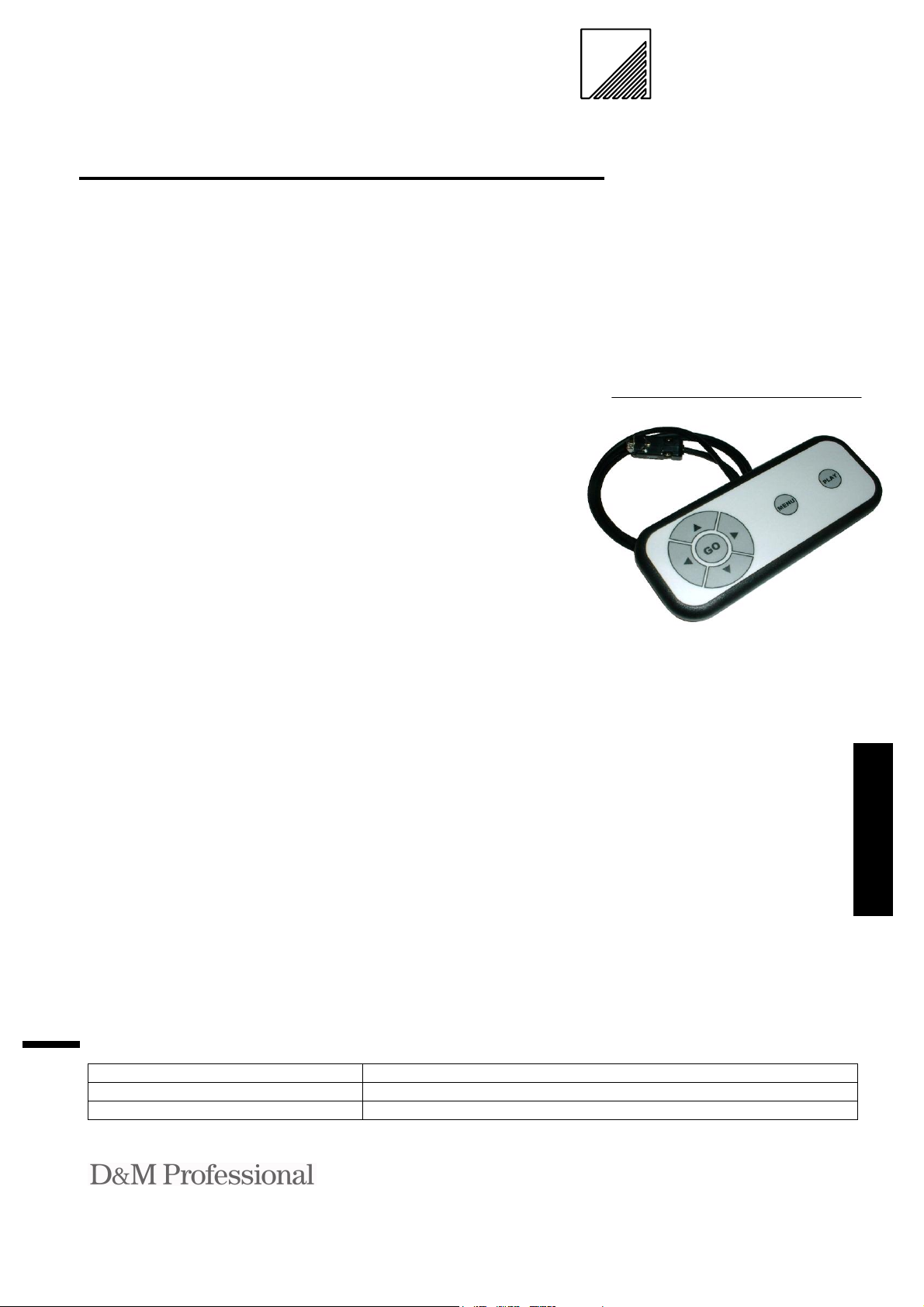
Wired Controller for the
®
Denon
V300 player
Technical Data
Firmware revision 1.00
DVD-DWRC(+) controller
.co .uk
.co .uk
.co .uk
.co .uk
Features
• Designed for Point-of-Sale,
training / educational, museums and presentation applications
• Ultra low power consumption
• Simple connection to Denon
V300 player serial port
• Assign 32 sets of functions to
the seven buttons with internal DIP switch
• Plug and Play
• Water resistant polycarbon-
ate membrane with under
surface tactile buttons (buttons and membrane replaceable)
• Upgradeable with Passive
Infrared sensor to allow pedestrian activation of presentation
Selection Guide
Description Part Number
Wired controller DVD-DWRC
Wired controller with PIR fitted DVD-DWRC+
Description
The DVD-DWRC unit permits the
control of DVD, CD Audio or
VCD media on a Denon
player.
Designed for Point-of-Sale, train-
®
ing / educational, museums and
presentation applications the unit
provides simple control of the media with seven (7) configurable
buttons. These buttons may be
configured with an internal switch
to one of thirty two (32) button
sets to fit the desired application
and provide authoring flexibility.
The housing is ergonomically designed to fit comfortably in the
hand or be surface mounted using
the integrated key-hole slots in the
base. The polycarbonate button
membrane is water resistant (ie.
inadvertent coffee, tea or soft
drink spills) and operates the under surface buttons which are fully
replaceable.
The DVD-DWRC also features an
internal socket for a user upgradeable Passive Infrared sensor.
Already fitted on DVD-DWRC+.
®
V300
This sensor allows the inserted
media to be activated, played, by a
passer-by (pedestrian) when used
within a kiosk environment where,
for example, a DVD player system
is used to provide Point-of-Sale
(POS) advertising.
Applications
The DVD-DWRC is designed
for Point-of-Sale, training /
educational, museums and
presentation applications.
Custom designed labels and firmware are
available for this product, please contact
your distributor*.
Distributed by : Page 1 of 4 V1.00
Kingsbridge House, Padbury Oaks Tel: +44 1753 680023
575-583 Bath Road, Longford Fax: +44 1753 686020
Middlesex UB7 0EH Email: sales@dm-pro.eu
United Kingdom
Page 2
Power requirements
The DVD-DWRC is powered from
the serial port RTS line of the connected DVD player. The maximum
current draw is 6mA.
DVD-DWRC interface
The DVD-DWRC interface connection is a standard DB9 male as
specified within the V300 player
specification.
Serial communication protocol is
9600 Baud, 1 Start bit, 8 Data bits, 1
Stop bits, No parity for all control
commands. All I/O is RS232 and
TTL compatible.
DVD-DWRC interface
Function DB9 Male
RTS 8
RXD 3
TXD 2
Ground 5
All other connection are N/C
DVD control protocol
The DVD-DWRC communicates
with each player using the player
control protocol. This protocol takes
the form of ASCII command strings
of format:
[PC,RC,nn]\r
Where nn is a remote control code
for the assigned button.
DVD-DWRC function
Upon player power-up the DVDDWRC awaits a button press upon
which the assigned RC code is sent
to the player.
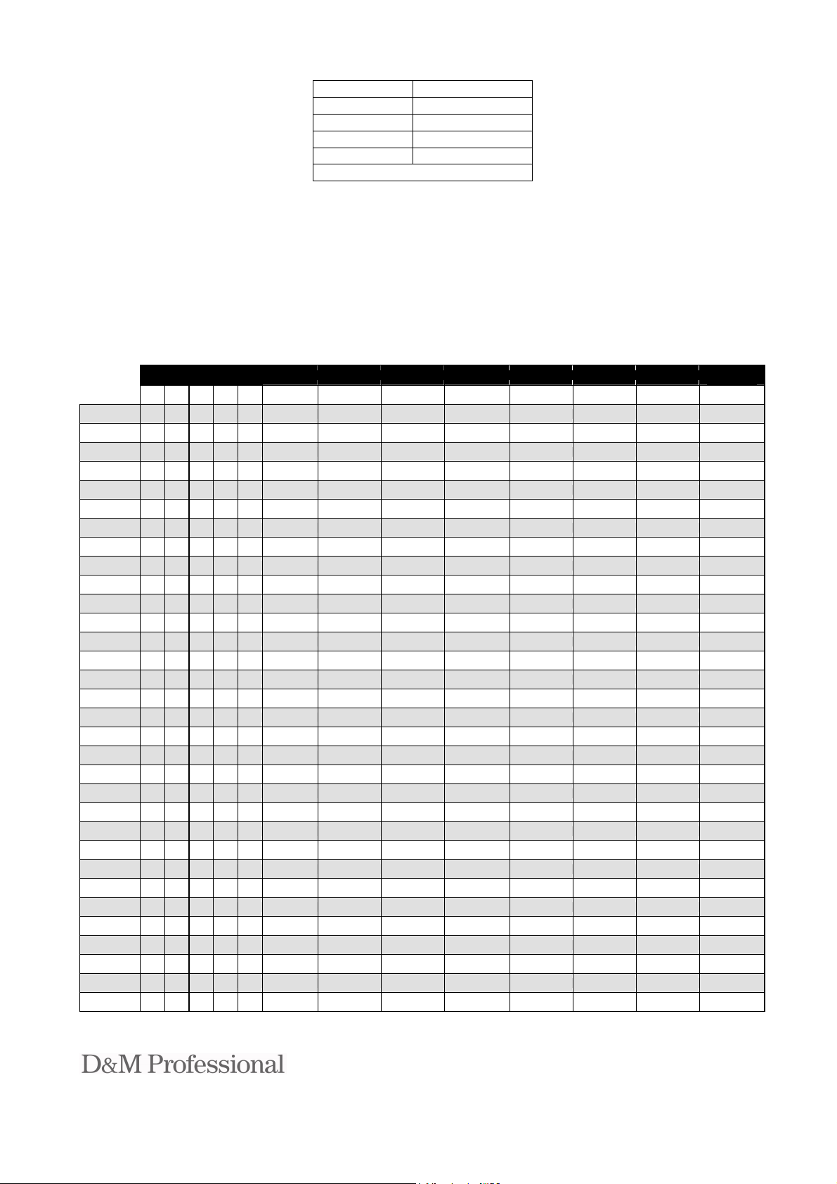
Custom button sets may be assigned
using the internal DIP switch, see
‘Installation’ on the next page.
Table 1.0 (Custom button settings)
Standard
Option 2
Option 3
Option 4
Option 5
Option 6
Option 7
Option 8
Option 9
Option 10
Option 11
Option 12
Option 13
Option 14
Option 15
Option 16
Option 17
Option 18
Option 19
Option 20
Option 21
Option 22
Option 23
Option 24
Option 25
Option 26
Option 27
Option 28
Option 29
Option 30
Option 31
Option 32
Dipswitch
0=OFF 1=ON
5 4 3 2 1
0 0 0 0 0 L
0 0 0 0 1 Left Up Right Down Go Menu Audio Play
0 0 0 1 0 Left Up Right Down Go Menu Subtitle Play
0 0 1 1 Left Up Right Down Go Audio Subtitle Play
0
0 0 1 0 0 Left Up Right Down Go Menu Return Play
0 0 1 0 1 Left Up Right Down Go Skip- Skip+ Play
0 0 1 1 0 Left Up Right Down Go Search- Search+ Play
0 0 1 1 1 Left Up Right Down Go Menu Pause Play
0 1 0 0 0 Left Up Right Down Go Down Go Play
0 1 0 0 1 Left Up Right Down Go Audio Angle Play
0 1 0 1 0 L
0 1 0 1 1 Left Up Right Down Go Angle Pause Play
0 1 1 0 0 Left Up Right Down Play No op. No op. Play
0 1 1 0 1 Left Up Right Down Play Menu Angle Play
0 1 1 1 0 Left Up Right Down Play Ski p- Skip+ Play
0 1 1 1 1 2 1 4 5 3 Menu Play Play
1 0 0 0 0 Ski p- 1 Skip+ 3 2 Menu Play Play
1 0 0 0 1 1 Skip+ 3 Skip- 2 Menu Play Play
1 0 0 1 0 2 1 3 4 No op. Menu Play Play
1 0 0 1 1 1 2 4 3 Play Menu Pause Play
1 0 1 0 0 2 1 3 4 Play Menu Pause Pl ay
1 0 1 0 1 1 2 3 4 Go Menu Pause Play
1 0 1 1 0 4 1 2 3 Go Menu Pause Play
1 0 1 1 1 Left Up Right Down Go Menu No op. Play
1 1 0 0 0 2 2 4 5 3 Ski p- Skip+ Play
1 1 0 0 1 Search- Up Search+ Down Go Menu Pause Play
1 1 0 1 0 Search- Up Search+ Down Pause Menu Go Play
1 1 0 1 1 Skip- Up Skip+ Down Pause Menu Go Play
1 1 1 0 0 Search- 1 Search+ 3 2 Menu Pause Play
1 1 1 0 1 Skip- Angle Skip+ Down Go Menu Pause Play
1 1 1 1 0 1 2 4 3 Pause Menu Return Play
1 1 1 1 1 Skip- Up Skip+ Down Go Menu Return Play
Button 1 Button 2 Button 3 Button 4 Button 5 Button 6 Button 7
eft
eft
PIR
(optional)
p
U
p
U
ight
R
ight
R
D
D
own
own
o
G
o
G
M
ubtitle
S
enu
A
P
ngle
lay
lay
P
lay
P
Distributed by : Page 2 of 4 V1.00
Kingsbridge House, Padbury Oaks Tel: +44 1753 680023
575-583 Bath Road, Longford Fax: +44 1753 686020
Middlesex UB7 0EH Email: sales@dm-pro.eu
United Kingdom
Page 3

Installation
1. The controller may be hand-held or surface mounted to a panel. Four M3 x 20mm stainless steel screws are
supplied to replace the screws in the base of the DVD-DWRC when mounting to a panel of 1 to 5mm thick.
2. If button function other than the standard UP, DOWN, LEFT, RIGHT, GO, MENU & PLAY is required then
remove the four (4) screws in the base of the controller, lift off the top cover and set the DIP switch (SW8 Option Select) to the option setting in Table 1.0 on the previous page.
3. Ensuring that power to the Denon V300 player is switched OFF insert the lead from the controller into the se-
rial connector on the rear of the Denon V300 player and secure with the integral screw-locks.
4. Switch ON the Denon V300 player and test by pressing each of the buttons.
PIR installation (Not required on the DVD-DWRC+)
1. The DVD-DWRC controller may be optionally fitted with a Passive Infrared (PIR) motion sensor to allow the
DVD presentation to be controlled when a passer-by (pedestrian) is detected.
2. To install the sensor remove the four (4) screws in the base of the controller, lift off the top cover, locate the
three (3) way socket marked ‘SN1’ and without touching the pins of the sensor, which could cause static damage, insert it into the socket.
3. With a sharp modelling knife remove the label covering the 10mm hole that mates with the sensor (TIP: Make
a cross-cut in the label from the inside of the top cover and then from the front remove the label material by
following the hole around using the knife tip in a punching motion).
4. Replace the front cover of the controller, with PIR tip protruding through hole, and re-secure with the four (4)
screws.
When the Denon V300 is now powered up, and after 30 seconds of stability time, the PIR will activate the button command setup on the Option Select switch (see Table 1.0) and then wait 10 seconds before re-enabling itself. If a button on
the controller is pressed at any time the 10 second timeout is re-started to prevent PIR activity from repeatedly sending
button presses.
Electrical Characteristics (TA= 25oC Typical)
Parameter Minimum Maximum Units Notes
Supply Voltage (RTS) 4.5 9 V
Supply Current - 6 mA
RXData output high level GND 0.8 V
RXData output low level 2.4 VCC V
Absolute Maximum Ratings
Parameter Minimum Maximum Units
Supply Voltage (RTS) -0.5 +10 V
Environmental
Parameter Minimum Maximum Units
Operating Temperature 0 70
Storage Temperature -10 80
Humidity 0 80
Dimensions See below
Weight 200g
Immunity & emissions EMC compliance to 89/336/EEC
o
o
%
C
C
WEEE Consumer Notice
This product is subject to Directive 2002/96/EC of the European Parliament and the Council of the European Union on Waste of Electrical and Electronic Equipment (WEEE) and, in jurisdictions adopting that
Directive, is marked as being put on the market after August 13, 2005, and should not be disposed of as
unsorted municipal/public waste. Please utilise your local WEEE collection facilities in the disposition and
otherwise observe all applicable requirements. For further information on the requirements regarding the disposition of
this product in other languages please visit www.designersystems.co.uk
Distributed by : Page 3 of 4 V1.00
Kingsbridge House, Padbury Oaks Tel: +44 1753 680023
575-583 Bath Road, Longford Fax: +44 1753 686020
Middlesex UB7 0EH Email: sales@dm-pro.eu
United Kingdom
Page 4

Mechanical Specifications – Units millimetres (inches)
2000 (79)
GO
Mounting hole detail (top view)
Four (4) M3x20mm screws are provided
D3.5mm x4
MENU PLAY
179 (7)
CENTRE
74 (2.9)
26.0 26.0
63.0 50.5
Declaration of Conformity Copyright 1999-2006 by DESIGNER SYSTEMS Co.
Apparatus name / model number DVD-DWRC(+) Manufacturer Designer Systems, 15 Andrew Place, Truro, Cornwall
Conformity via Generic Standard EN50081-1 TR1 3HZ, United Kingdom
Generic Standard EN50082-1 Description of apparatus DVD control device
Conformity criteria For use only within commercial, residential and light industrial applications
We certify that the apparatus identified above conforms to the requirements of Council Directive 89/336/EEC & 73/23/EEC
Signed. Date 1/10/99
Having made this declaration the CE mark is affixed to this product, its packaging, manual or warranty.
The information appearing in this Datasheet is believed to be accurate at the time of publication. However, Designer Systems assumes no responsibility arising from the use o f the information supplied. The applications ment ioned herein are used solely for the purpose o f illustration and Designer Systems makes no warranty or representation that such applications will be
suitable without further mod ification, nor recommends the use of its products for application that may present a risk to human life due to malfunct ion or otherwise. Designer Systems reserves
the right to alter its products without prior notification. For the most up-to-date information, please visit our web site at http://www.designersystems.co.uk
Distributed by : Page 4 of 4 V1.00
Kingsbridge House, Padbury Oaks Tel: +44 1753 680023
575-583 Bath Road, Longford Fax: +44 1753 686020
Middlesex UB7 0EH Email: sales@dm-pro.eu
United Kingdom
 Loading...