

Page 1
Designer
DVD
ACCESSORIES
Designer
DesignerDesigner
Systems
Systems
SystemsSystems
B
espoke Electronic Design & Manufacturing in the UK
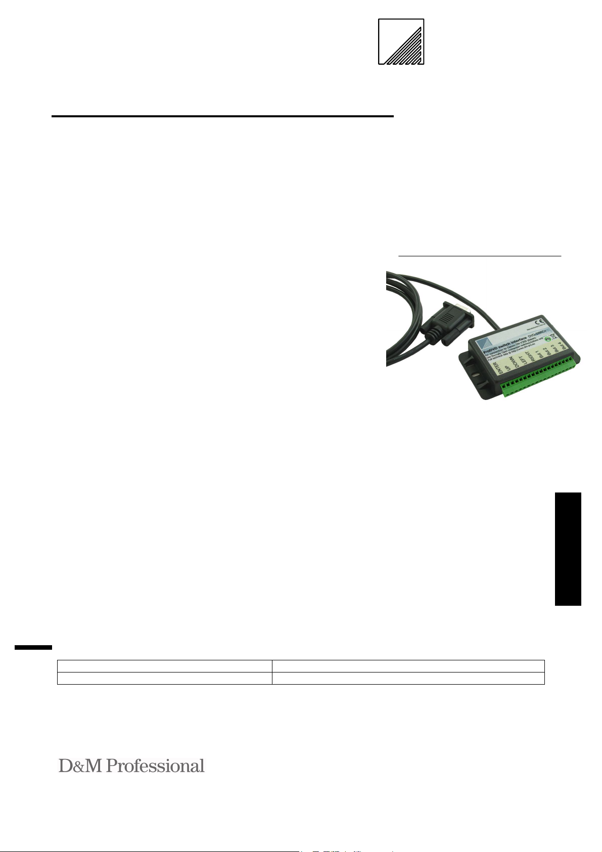
9 Channel Switch Interface
®
for the Denon
V300 player
Technical Data
Firmware revision 1.00
DVD-D9RC+ interface
.co .uk
.co .uk
.co .uk
.co .uk
Features
• Ultra low power consumption from the connected
player
• Simple connection to Denon
V300 player serial (RS232)
port
• Standard DVD-D9RC+ version provides UP/DOWN
/LEFT/RIGHT and ENTER
(3 other versions also available from your distributor)
• Screw terminals for quick
connection to Normally
Open (NO) switch contacts
• Anti-bounce on all switch
inputs
• Enclosure lugs provide simple secure fixing
Description
The DVD-D9 interfaces permit
nine Normally Open (NO) momentary action switches the con-
®
trol of a Denon
The DVD-D9 range emulate a
standard external control device by
issuing PlayC, PlayT and RC commands that control the action performed by the player.
The DVD-D9RC+ issues cursor
UP/DOWN/LEFT/RIGHT, ENTER and number buttons 1-4 the
same as the IR remote control.
Other versions are also available
from your distributor, the DVDD9CH issues PlayC commands for
DVD media, the DVD-D9DA issues PlayT commands for CD-DA
& VCD media and the DVDD9RC issues cursor UP/DOWN,
ENTER and buttons 1-6 the same
as the IR remote control.
®
V300 player.
Applications
The DVD-D9 range is primarily for use within a kiosk environment where input is required
from the kiosk control buttons
or from an Anti-Vandal button
plate such as the DVD-nBUT.
The devices are especially designed to connect to any type of
momentary action switch and
can therefore be used to control
the DVD player in a number
diverse applications.
Custom designed firmware is available for
this product, please contact your distributor.
Selection Guide
Description Part Number
Remote control switch interface + DVD-D9RC+
Distributed by : Page 1 of 4 V1.00
Kingsbridge House, Padbury Oaks Tel: +44 1753 680023
575-583 Bath Road, Longford Fax: +44 1753 686020
Middlesex UB7 0EH Email: sales@dm-pro.eu
United Kingdom
Page 2
Power requirements
The DVD-D9 range are powered
from the serial port RTS line of the
connected DVD player. The maximum current draw is 6mA.
Switch Inputs
The DVD-D9 switch interface consists of a series of nine double terminal blocks to which any Normally
Open (NO) momentary switch can
be connected.
Contacts may be wired up to 100
metres away from the DVD-D9
without degrading the performance
of the device.
DVD-D9 interface
The DVD-D9 interface connection
is a standard DB9 male as specified
within the V300 player specification.
Serial communication protocol is
9600 Baud, 1 Start bit, 8 Data bits, 1
Stop bits, No parity for all control
commands. All I/O is RS232 and
TTL compatible.
DVD control protocol
The DVD-D9 communicates with
the player using the player control
protocol . This protocol takes the
form of ASCII command strings of
format:
[PC,RC,44]\r
\r – Carriage return
These strings allow the PlayC (Play
Chapter), PlayT (Play Title/Track)
or RC (Remote control) commands
to be issued to the player in response
to an external button on the DVDD9 being pressed.
See button function tables at the end
of the document.
NOTE: For further information on
the DVD-D9CH, DVD-D9DA or
DVD-D9RC please see the relevant datasheet.
DVD-D9 interface
Function DB9 Male
RTS 8
RXD 3
TXD 2
Ground 5
All other connection are N/C
Electrical Characteristics (TA= 25oC Typical)
Parameter Minimum Maximum Units Notes
Supply Voltage (RTS) 4.5 9 V
Supply Current - 6 mA
Switch resistance - 100
Switch de-bounce time - 50 mS
RXData high level GND 0.8 V
RXData low level 2.4 VCC V
Terminal wire thickness 0.5 1.3 mm
2
Absolute Maximum Ratings
Parameter Minimum Maximum Units
Supply Voltage (RTS) -0.5 +10 V
Environmental
Parameter Minimum Maximum Units
Operating Temperature 0 70
Storage Temperature -10 80
Humidity 0 80
Dimensions See below
Weight 150g
Immunity & emissions EMC compliance to 89/336/EEC
o
o
%
C
C
Distributed by : Page 2 of 4 V1.00
Kingsbridge House, Padbury Oaks Tel: +44 1753 680023
575-583 Bath Road, Longford Fax: +44 1753 686020
Middlesex UB7 0EH Email: sales@dm-pro.eu
United Kingdom
Page 3

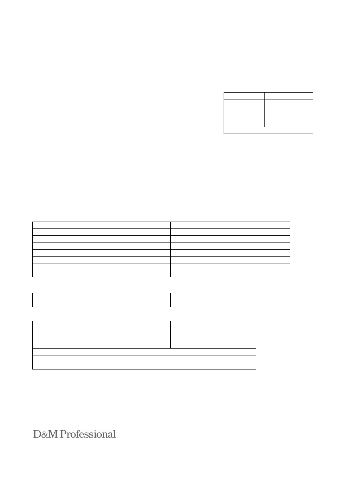
Mechanical Specifications – Units millimetres (inches)
Switch input No.
2000 (79)
92 (3.62)
Normally Open switch connections
52 (2.04)
Installation
1. Ensure power to the Denon DN-V300 player is switched OFF.
2. Insert the lead on the DVD-D9RC+ into the I/O connector on the rear of the Denon DN-V300 player and secure
with the integral screw-locks.
3. Connect a Normally Open (NO) momentary action button across each of the inputs you wish to use (Note: each
double terminal block is one input) using a pair of wires or multi-conductor cable to a maximum length of 50 metres using a small flat blade screwdriver.
(NB. For a ready-made aluminium button plate with sealed anti-vandal buttons see the Designer Systems DVDnBUT solution)
4. Site the DVD-D9 in a location that will not put undue strain on the terminals.
5. Switch ON the Denon DN-V300 player and test by pressing each of the wired in buttons cross referencing with the
table below. Should the installation not function, switch OFF immediately and check all connections.
Function
1 Button ENTER
2 Button arrow UP
3 Button arrow DOWN
4 Button arrow LEFT
5 Button arrow RIGHT
6 Button 1
7 Button 2
8 Button 3
9 Button 4
Notes:
• The DVD-D9RC+ must NEVER be connected to voltage bearing circuits; damage to the unit and the Denon DN-
Distributed by : Page 3 of 4 V1.00
Kingsbridge House, Padbury Oaks Tel: +44 1753 680023
575-583 Bath Road, Longford Fax: +44 1753 686020
Middlesex UB7 0EH Email: sales@dm-pro.eu
United Kingdom
V300 player will result and will invalidate the Warranty.
Page 4

WEEE Consumer Notice
This product is subject to Directive 2002/96/EC of the European Parliament and the Council of the European Union on Waste of Electrical and Electronic Equipment (WEEE) and, in jurisdictions adopting that
Directive, is marked as being put on the market after August 13, 2005, and should not be disposed of as
unsorted municipal/public waste. Please utilise your local WEEE collection facilities in the disposition and
otherwise observe all applicable requirements. For further information on the requirements regarding the disposition of
this product in other languages please visit www.designersystems.co.uk
Declaration of Conformity Copyright 1999-2006 by DESIGNER SYSTEMS Co.
Apparatus name / model number DVD-9 Manufacturer Designer Systems, 15 Andrew Place, Truro, Cornwall
Conformity via Generic Standard EN50081-1 TR1 3HZ, United Kingdom
Generic Standard EN50082-1 Description of apparatus DVD control device
Conformity criteria For use only within commercial, residential and light industrial applications
We certify that the apparatus identified above conforms to the requirements of Council Directive 89/336/EEC & 73/23/EEC
Signed. Date 1/10/99
Having made this declaration the CE mark is affixed to this product, its packaging, manual or warranty.
The information appearing in this Operation Note is believed t o be accurate at the time of pu blication. However, Designer S ystems assumes no responsibility ar ising from the use of the
information supplied. The applicat ions mentioned herein are used so lely for the purpose of illustrat ion and Designer Systems makes no warrant y or representation that such applicat ions will
be suitable without further mod ification, nor recommends the use of its pro ducts for application that may present a risk to human life due to malfunction or ot herwise. Designer Systems
reserves the right to alter its products without pr ior notification. For the most up-to-date information, please visit o ur web site at http://www.designersystems.co.uk
Distributed by : Page 4 of 4 V1.00
Kingsbridge House, Padbury Oaks Tel: +44 1753 680023
575-583 Bath Road, Longford Fax: +44 1753 686020
Middlesex UB7 0EH Email: sales@dm-pro.eu
United Kingdom
 Loading...