

Page 1
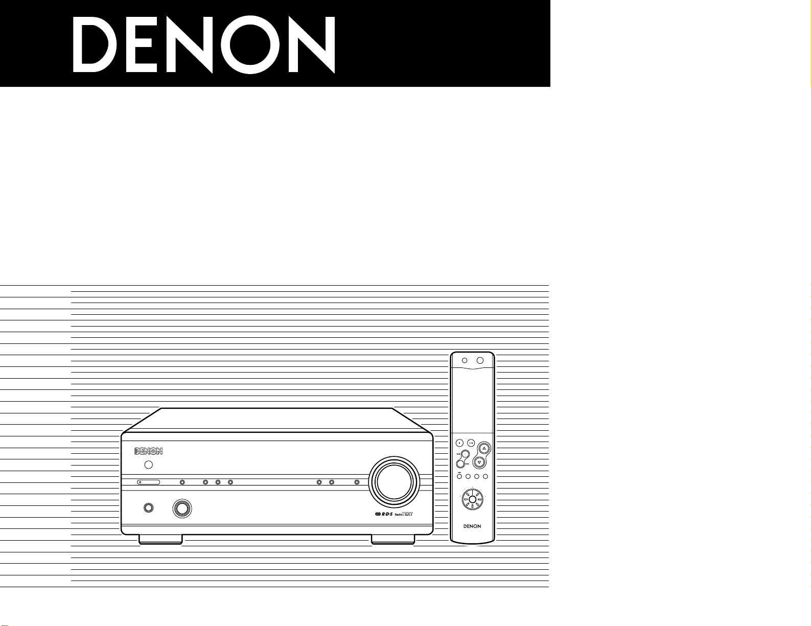
STEREO RECEIVER
DRA-201SA
RC-906
REMOTE CONTROL UNIT
CLEAR
123
546
789
+1010
CD SRS
MDTAPECD-R
TUNING
REV.
MODE
Dolby NR
REPEAT
CALL
PROG/
DIRECT
RANDOM
BAND
RDS
DIMMER
TIME/
PANEL
TIME EDIT
SYSTEM
POWER
OFF ON
STOP PLAY
VOLUME
/SELECT
SLEEP MODE
TAPE
FUNCTION
PRESET
+
-
TUNER
CD
CD-R
MD
TAPE
CH
MHz
TUNED STEREO AUTO
TIMER
BAND
/ RDS
MEMORY
/ SET DOWN UP
PRESET / TUNING
PHONES FUNCTION
VOLUME
SOURCE DIRECT
MODEON / STANDBY
STEREO RECEIVERER DRA-201SA
OPERATING INSTRUCTIONS
BEDIENUNGSANLEITUNG
MODE D’EMPLOI
ISTRUZIONI PER L’USO
INSTRUCCIONES DE OPERACION
GEBRUIKSAANWIJZING
BRUKSANVISNING
FOR ENGLISH READERS PAGE 004 ~ PAGE 020
FÜR DEUTSCHE LESER SEITE 021 ~ SEITE 037
POUR LES LECTEURS FRANCAIS PAGE 038 ~ PAGE 054
PER IL LETTORE ITALIANO PAGINA 055 ~ PAGINA 071
PARA LECTORES DE ESPAÑOL PAGINA 072 ~ PAGINA 088
VOOR NEDERLANDSTALIGE LEZERS PAGINA 089 ~ PAGINA 105
FOR SVENSKA LÄSARE SIDA 106 ~ SIDA 121
Page 2
2
NOTE ON USE / HINWEISE ZUM GEBRAUCH /
OBSERVATIONS RELATIVES A L’UTILISATION / NOTE SULL’USO
NOTAS SOBRE EL USO / ALVORENS TE GEBRUIKEN / OBSERVERA
• Avoid high temperatures.
Allow for sufficient heat dispersion when
installed on a rack.
• Vermeiden Sie hohe Temperaturen.
Beachten Sie, daß eine ausreichend
Luftzirkulation gewährleistet wird, wenn das
Gerät auf ein Regal gestellt wird.
• Eviter des températures élevées
Tenir compte d’une dispersion de chaleur
suffisante lors de l’installation sur une
étagère.
• Evitate di esporre l’unità a temperature alte.
Assicuratevi che ci sia un’adeguata
dispersione del calore quando installate
l’unità in un mobile per componenti audio.
• Evite altas temperaturas
Permite la suficiente dispersión del calor
cuando está instalado en la consola.
• Vermijd hoge temperaturen.
Zorg voor een degelijk hitteafvoer indien het
apparaat op een rek wordt geplaatst.
• Undvik höga temperaturer.
Se till att det finns möjlighet till god
värmeavledning vid montering i ett rack.
• Keep the set free from moisture, water, and
dust.
• Halten Sie das Gerät von Feuchtigkeit,
Wasser und Staub fern.
• Protéger l’appareil contre l’humidité, l’eau et
lapoussière.
• Tenete l’unità lontana dall’umidità, dall’acqua
e dalla polvere.
• Mantenga el equipo libre de humedad, agua
y polvo.
• Laat geen vochtigheid, water of stof in het
apparaat binnendringen.
• Utsätt inte apparaten för fukt, vatten och
damm.
• Do not let foreign objects in the set.
• Keine fremden Gegenstände in das Gerät
kommen lassen.
• Ne pas laisser des objets étrangers dans
l’appareil.
• E’ importante che nessun oggetto è inserito
all’interno dell’unità.
• No deje objetos extraños dentro del equipo.
• Laat geen vreemde voorwerpen in dit
apparaat vallen.
• Se till att främmande föremål inte tränger in
i apparaten.
• Handle the power cord carefully.
Hold the plug when unplugging the cord.
• Gehen Sie vorsichtig mit dem Netzkabel um.
Halten Sie das Kabel am Stecker, wenn Sie
den Stecker herausziehen.
• Manipuler le cordon d’alimentation avec
précaution.
Tenir la prise lors du débranchement du
cordon.
• Manneggiate il filo di alimentazione con
cura.
Agite per la spina quando scollegate il cavo
dalla presa.
• Maneje el cordón de energía con cuidado.
Sostenga el enchufe cuando desconecte el
cordón de energía.
• Hanteer het netsnoer voorzichtig.
Houd het snoer bij de stekker vast wanneer
deze moet worden aan- of losgekoppeld.
• Hantera nätkabeln varsamt.
Håll i kabeln när den kopplas från el-uttaget.
• Unplug the power cord when not using the
set for long periods of time.
• Wenn das Gerät eine längere Zeit nicht
verwendet werden soll, trennen Sie das
Netzkabel vom Netzstecker.
• Débrancher le cordon d’alimentation lorsque
l’appareil n’est pas utilisé pendant de
longues périodes.
• Disinnestate il filo di alimentazione quando
avete l’intenzione di non usare il filo di
alimentazione per un lungo periodo di
tempo.
• Desconecte el cordón de energía cuando no
utilice el equipo por mucho tiempo.
• Neem altijd het netsnoer uit het stopkontakt
wanneer het apparaat gedurende een lange
periode niet wordt gebruikt.
• Koppla ur nätkabeln om apparaten inte
kommer att användas i lång tid.
• Do not let insecticides, benzene, and thinner
come in contact with the set.
• Lassen Sie das Gerät nicht mit Insektiziden,
Benzin oder Verdünnungsmitteln in
Berührung kommen.
• Ne pas mettre en contact des insecticides,
du benzène et un diluant avec l’appareil.
• Assicuratevvi che l’unità non venga in
contatto con insetticidi, benzolo o solventi.
• No permita el contacto de insecticidas,
gasolina y diluyentes con el equipo.
• Laat geen insektenverdelgende middelen,
benzine of verfverdunner met dit apparaat in
kontakt komen.
• Se till att inte insektsmedel på spraybruk,
bensen och thinner kommer i kontakt med
apparatens hölje.
• Never disassemble or modify the set in any
way.
• Versuchen Sie niemals das Gerät
auseinander zu nehmen oder auf jegliche Art
zu verändern.
• Ne jamais démonter ou modifier l’appareil
d’une manière ou d’une autre.
• Non smontate mai, nè modificate l’unità in
nessun modo.
• Nunca desarme o modifique el equipo de
ninguna manera.
• Nooit dit apparaat demonteren of op andere
wijze modifiëren.
• Ta inte isär apparaten och försök inte bygga
om den.
• Do not obstruct the ventilation holes.
• Die Belüftungsöffnungen dürfen nicht
verdeckt werden.
• Ne pas obstruer les trous d’aération.
• Non coprite i fori di ventilazione.
• No obstruya los orificios de ventilación.
• De ventilatieopeningen mogen niet worden
beblokkeerd.
• Täpp inte till ventilationsöppningarna.
* (For sets with ventilation holes)
ENGLISHDEUTSCHFRANCAISITALIANOESPAÑOLNEDERLANDSSVENSKA
CAUTION
CAUTION: TO REDUCE THE RISK OF ELECTRIC SHOCK, DO
NOT REMOVE COVER (OR BACK). NO USER
SERVICEABLE PARTS INSIDE. REFER SERVICING
TO QUALIFIED SERVICE PERSONNEL.
The lightning flash with arrowhead symbol, within an equilateral triangle,
is intended to alert the user to the presence of uninsulated “dangerous
voltage” within the product’s enclosure that may be of sufficient
magnitude to constitute a risk of electric shock to persons.
The exclamation point within an equilateral triangle is intended to alert the
user to the presence of important operating and maintenance (servicing)
instructions in the literature accompanying the appliance.
WARNING: TO REDUCE THE RISK OF FIRE OR ELECTRIC SHOCK, DO
NOT EXPOSE THIS APPLIANCE TO RAIN OR MOISTURE.
• DECLARATION OF CONFORMITY
We declare under our sole responsibility that this
product, to which this declaration relates, is in
conformity with the following standards:
EN60065, EN55013, EN55020, EN61000-3-2 and
EN61000-3-3.
Following the provisions of 73/23/EEC, 89/336/EEC and
93/68/EEC Directive.
• ÜBEREINSTIMMUNGSERKLÄRUNG
Wir erklären unter unserer Verantwortung, daß dieses
Produkt, auf das sich diese Erklärung bezieht, den
folgenden Standards entspricht:
EN60065, EN55013, EN55020, EN61000-3-2 und
EN61000-3-3.
Entspricht den Verordnungen der Direktive 73/23/EEC,
89/336/EEC und 93/68/EEC.
• DECLARATION DE CONFORMITE
Nous déclarons sous notre seule responsabilité que
l’appareil, auquel se réfère cette déclaration, est
conforme aux standards suivants:
EN60065, EN55013, EN55020, EN61000-3-2 et
EN61000-3-3.
D’après les dispositions de la Directive 73/23/EEC,
89/336/EEC et 93/68/EEC.
• DICHIARAZIONE DI CONFORMITÀ
Dichiariamo con piena responsabilità che questo
prodotto, al quale la nostra dichiarazione si riferisce, è
conforme alle seguenti normative:
EN60065, EN55013, EN55020, EN61000-3-2 e
EN61000-3-3.
In conformità con le condizioni delle direttive 73/23/EEC,
89/336/EEC e 93/68/EEC.
QUESTO PRODOTTO E’ CONFORME
AL D.M. 28/08/95 N. 548
• DECLARACIÓN DE CONFORMIDAD
Declaramos bajo nuestra exclusiva responsabilidad que
este producto al que hace referencia esta declaración,
está conforme con los siguientes estándares:
EN60065, EN55013, EN55020, EN61000-3-2 y EN610003-3.
Siguiendo las provisiones de las Directivas 73/23/EEC,
89/336/EEC y 93/68/EEC.
• EENVORMIGHEIDSVERKLARING
Wij verklaren uitsluitend op onze verantwoordelijkheid
dat dit produkt, waarop deze verklaring betrekking heeft,
in overeenstemming is met de volgende normen:
EN60065, EN55013, EN55020, EN61000-3-2 en
EN61000-3-3.
Volgens de bepalingen van de Richtlijnen 73/23/EEC,
89/336/EEC en 93/68/EEC.
• ÖVERENSSTÄMMELSESINTYG
Härmed intygas helt på eget ansvar att denna produkt,
vilken detta intyg avser, uppfyller följande standarder:
EN60065, EN55013, EN55020, EN61000-3-2 och
EN61000-3-3.
Enligt stadgarna i direktiv 73/23/EEC, 89/336/EEC och
93/68/EEC.
CAUTION
• The ventilation should not be impeded by covering the ventilation openings with items, such as newspapers, table-cloths,
curtains, etc.
• No naked flame sources, such as lighted candles, should be placed on the apparatus.
• Please be care the environmental aspects of battery disposal.
• The apparatus shall not be exposed to dripping or splashing for use.
• No objects filled with liquids, such as vases, shall be placed on the apparatus.
RISK OF ELECTRIC SHOCK
DO NOT OPEN
Page 3
3
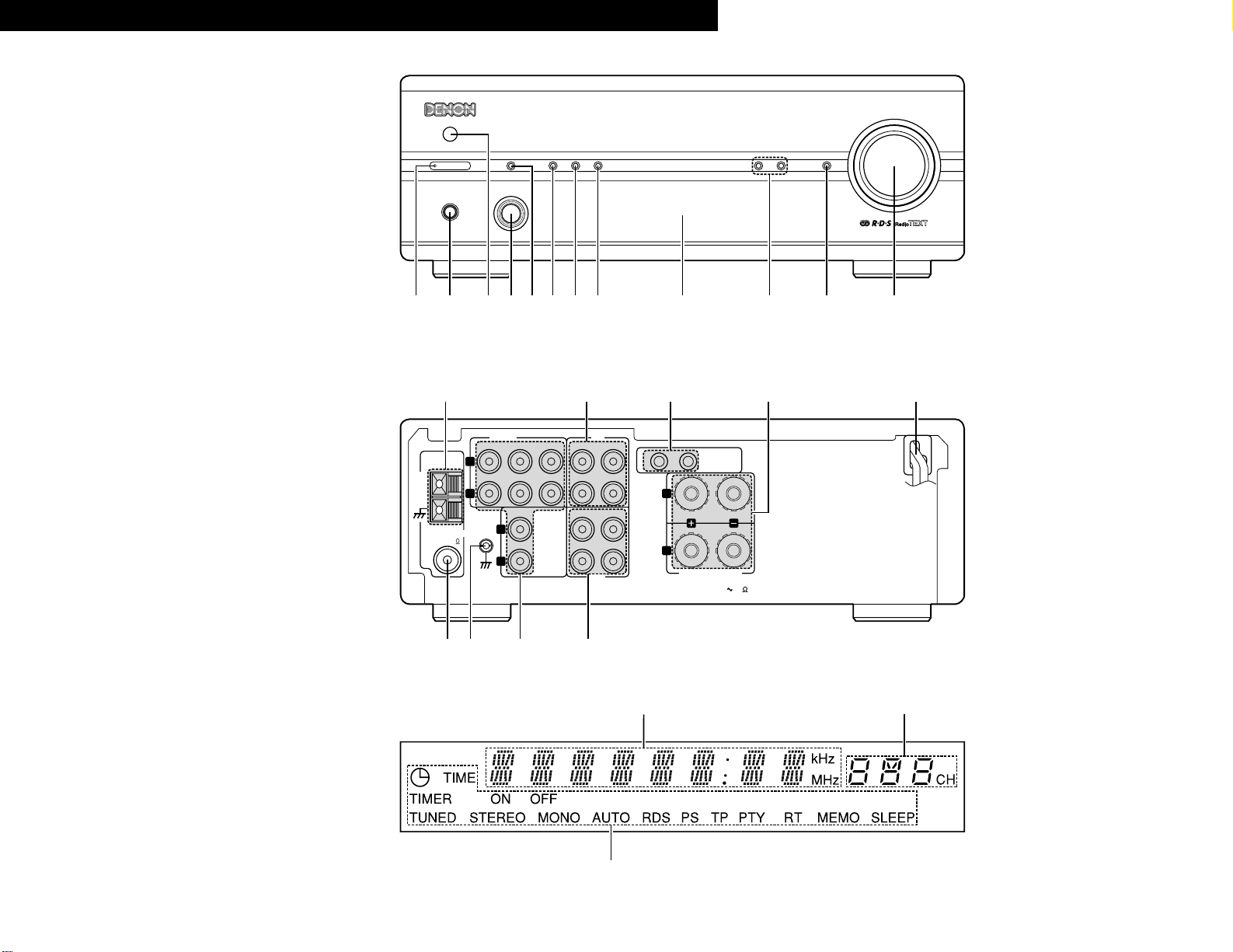
FRONT PANEL
FRONTPLATTE
PANNEAU AVANT
PANNELLO ANTERIORE
PANEL FRONTAL
VOORPANEEL
FRONT PANELEN
REAR PANEL
RÜCKWAND
PANNEAU ARRIERE
IL PANNELLO POSTERIORE
PANEL TRASERO
ACHTERPANEEL
BAKSIDAN
CH
MHz
TUNED STEREO AUTO
TIMER
BAND
/ RDS
MEMORY
/ SET DOWN UP
PRESET / TUNING
PHONES FUNCTION
VOLUME
SOURCE DIRECT
MODEON / STANDBY
STEREO RECEIVERER DRA-201SA
q
w
ertyu
i
o!0 !1 !2
SIGNAL
GND
12
SYSTEM
CONNECTOR
L
R
SPEAKER SYSTEM
SPEAKER IMPEDANCE
4 16
CD
DVD/AUX
PHONO TAPE MD
AUX-2 TAPE MD
PB
REC
INPUTS
L
R
L
R
AM
LOOP
ANT.
FM COAX. 75
ANTENNA
!3 !4 !5 !6
!7!8!9@0@1
ENGLISH DEUTSCH FRANCAIS ITALIANO ESPAÑOL NEDERLANDS SVENSKA
DISPLAY
DISPLAY
AFFICHAGE
DISPLAY
VISUALIZADOR
DISPLAY
DISPLAYEN
@2
@3
@4
Page 4
4
ENGLISH
IMPORTANT TO SAFETY
WARNING:
TO PREVENT FIRE OR SHOCK HAZARD,
DO NOT EXPOSE THIS APPLIANCE TO
RAIN OR MOISTURE.
Please, record and retain the Model name and serial
number of your set shown on the rating label.
Model No. DRA-201SA Serial No.
Thank you for purchasing this DENON stereo receiver.
Please read the operation instructions thoroughly in order
to acquaint yourself with the stereo receiver and achieve
maximum satisfaction from it.
CAUTION
1. Handle the power supply cord carefully
Do not damage or deform the power supply cord. If it
is damaged or deformed, it may cause electric shock
or malfunction when used. When removing from wall
outlet, be sure to remove by holding the plug
attachment and not by pulling the cord.
2. Do not open the top cover
In order to prevent electric shock, do not open the top
cover.
3. Do not place anything inside
Do not place metal objects or spill liquid inside the
stereo receiver.
Electric shock or malfunction may result.
TABLE OF CONTENTS
z
MAIN FEATURES ………………………………………
4
x
BEFORE USING ………………………………………
4
c
CONNECTING THE ANTENNAS ……………………
5
v
CONNECTIONS ……………………………………
6, 7
b
PART NAMES AND FUNCTIONS …………………
8, 9
n
SYSTEM REMOTE CONTROL …………………
9~11
m
OPERATION ……………………………………
12, 13
,
LISTENING TO RADIO …………………………
13~15
.
USING THE TIMER ………………………………
16~18
⁄0
SYSTEM FUNCTIONS ………………………………
18
⁄1
TROUBLESHOOTING ………………………………
19
⁄2
SPECIFICATIONS ……………………………………
20
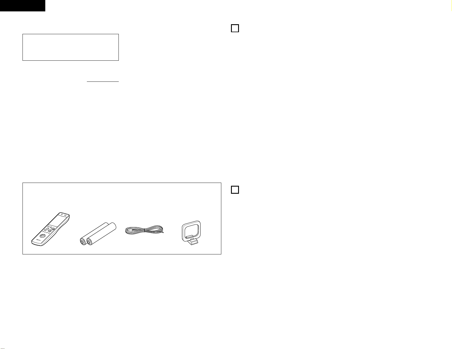
Check that the following parts are included in the package aside from the main unit:
2
ACCESSORIES
q Remote control unit (RC-906) …………………………1
w Batteries R03 (AAA) ……………………………………2
e FM indoor antenna ……………………………………1
r AM loop antenna ……………………………………1
t Operating instructions …………………………………1
y Service station list ……………………………………1
qwer
RC-906
R
E
M
O
T
E
C
O
N
T
R
O
L
U
N
I
T
C
L
E
A
R
5
5
C
D
S
R
S
M
D
T
A
P
E
C
D
-
R
T
U
N
I
N
G
R
E
V
.
M
O
D
E
D
O
L
B
Y
R
E
P
E
A
T
C
A
L
L
PROG/
DIRECT
R
A
N
D
O
M
B
A
N
D
P
T
Y
R
D
S
D
I
M
M
E
R
T
I
M
E
/
P
A
N
E
L
T
I
M
E
E
D
I
T
S
Y
S
T
E
M
P
O
W
E
R
O
F
F
O
N
S
T
O
P
P
L
A
Y
VO
LUM
E
/
S
E
L
E
C
T
S
L
E
E
P
M
O
D
E
T
A
P
E
F
U
N
C
T
I
O
N
P
R
E
S
E
T
+
-
T
U
N
E
R
C
D
C
D
R
M
D
T
A
P
E
+
-
1
23
64
7
8
9
+
10
0
1. HC-TR output circuit for both subtlety and power
A single push-pull circuit using an HC-TR (high current
transistor) based on the same principles as the UHCMOS used in the POA-S1, DENON’s top grade
monaural power amplifier, achieves both stable a high
current supply and excellent low level signal linearity.
The result is an extremely high level of both subtlety
and power.
2. Strong power circuitry supporting the expressive
abilities of the HC-TR output circuit
The strong power circuitry consisting of high speed
rectifier diodes and large high sound quality block
condensers allow the HC transistor output circuit to be
used to its maximum potential.
3. S.L.D.C.
The DRA-201SA uses an S.L.D.C. (Signal Level Divided
Construction) with the ideal separation of the different
circuits (low level signal circuit, high level signal circuit,
microprocessor circuit, etc.)
4. Source Direct function for improved sound quality
The DRA-201SA is equipped with a source direct
function that bypasses the bass, treble, loudness and
balance control circuits to achieve a simple signal path,
contributing to keeping the sound pure.
5. RDS compatible
Compatible with various RDS service, including
Program service name (PS), Program type identification
(PTY), Traffic program identification (TP), Clock time
(CT) and Radio text message (RT).
6. AM/FM tuner with random 40-station preset
function
7. System remote control unit
The DRA-201SA comes with a system remote control
unit that can be used to control the different
components in the 201SA series (CD player, MD
recorder and cassette deck, when used system
connections only).
8. Low standby power consumption
The power consumption when the power is in the
standby mode is reduced to 1W or less.
1
MAIN FEATURES
2
BEFORE USING
Read the following before using the set.
• Before turning on the power
Check again that all connections are correct and that
there are no problems with the connection cords. Be
sure to unplug the power cord before connecting or
disconnecting the connection cords.
• Moving the set
To prevent short-circuits or damage to the connection
cords, always unplug the power cord and disconnect
the connection cords between all other audio
components when moving the set.
• Store this instructions in safe place
After reading, store this instructions along with the
warranty in a safe place. Also fill in the items on the
back paper for your convenience.
• Illustrations in this manual
Note that some of the illustrations used for
explanations in this manual may differ from the actual
set.
Page 5
5
ENGLISH
3
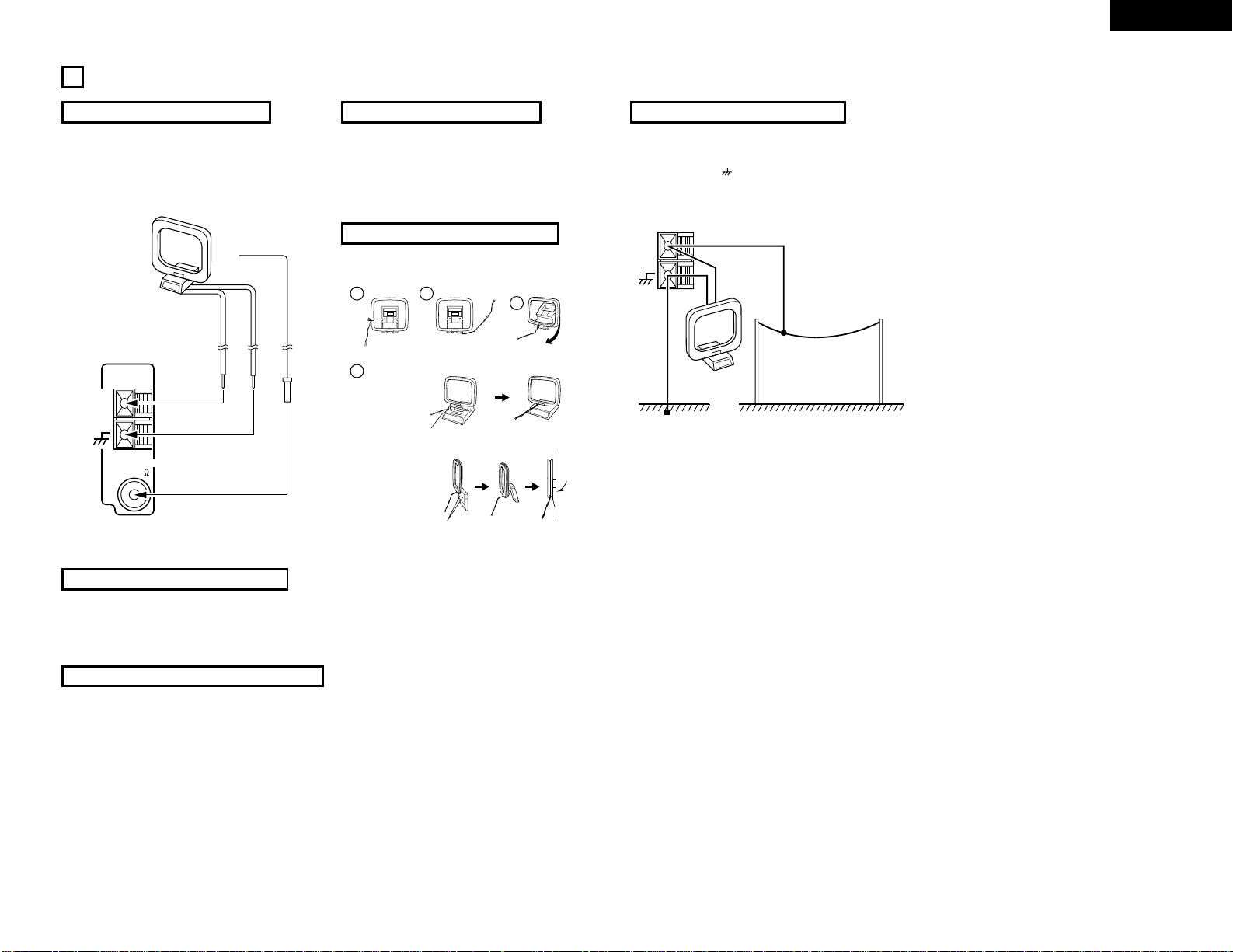
CONNECTING THE ANTENNAS
Installing the FM indoor antenna
Tune in FM station (see page 13), set the antenna so that
distortion and noise is minimal, then secure the tip of the
antenna in this position using tape or a pin.
Installing the AM loop antenna
Tune in an AM station (see page 13) and set the antenna
as far from the system as possible to keep distortion and
noise is minimal. In some cases, it is best to invert the
polarities. AM broadcasts cannot be received well if the
loop antenna is not connected or if it is set close to metal
objects.
Connecting an FM outdoor antenna
If good reception cannot be achieved with the included
FM antenna, use an FM outdoor antenna. Connect an IECtype connector to the coaxial cable and connect the
antenna to the FM COAX (75 Ω/ohms) terminal.
Selecting a place for the FM outdoor antenna
• Set the antenna so that it points towards the broadcast
station’s transmitting antenna. Behind buildings or
mountains, set the antenna in the position at which
reception is best, and also try changing the direction of
the antenna.
• Do not install the antenna under power lines.
Doing so is extremely dangerous, as the power line
could touch the antenna.
• Install the antenna away from roads or train tracks to
avoid noise from cars or trains.
• Do not install the antenna too high, as it may be hit by
lightning.
AM
LOOP
ANT.
FM COAX. 75
ANTENNA
FM antenna
AM loop antenna
Installing an AM outdoor antenna
Connect the signal wire from the AM outdoor antenna to
the antenna terminal. Be sure to connect the signal
ground wire to the terminal. Also be sure to connect
the included AM loop antenna.
AM
LOOP
ANT.
Signal ground
AM outdoor antenna
Assembling the AM loop antenna
Connect to the AM
antenna terminals.
Bend in the reverse
direction.
Remove the vinyl tie
and take out the
connection line.
Installation hole
Mount on wall, etc.
Mount
a. With the antenna
on top any stable
surface.
b. With the antenna
attached to a wall.
AM loop antenna
1
4
2
3
Page 6
6
ENGLISH
LINE
L
R
OUT IN
OUT 1
12
IN 2
OPTICAL
DIGITAL
CONNECTOR
SYSTEM
LINE
L
R
OUT IN
12
CONNECTOR
SYSTEM
12
CONNECTOR
SYSTEM
LINE OUT
L
R
1 OUT 2
OPTICAL
DIGITAL
SIGNAL
GND
12
SYSTEM
CONNECTOR
L
R
SPEAKER SYSTEM
SPEAKER IMPEDANCE
4 16
CD
DVD/AUX
PHONO TAPE MD
AUX-2 TAPE MD
PB
REC
INPUTS
L
R
L
R
AM
LOOP
ANT.
FM COAX. 75
ANTENNA
R
L
RLL
R
L
R
LRLRL
RRL
R
L
R
L
R
L
R
L
DVD
B
R
L
DIGITAL AUDIODIGITAL AUDIO
(L)
(R)
4
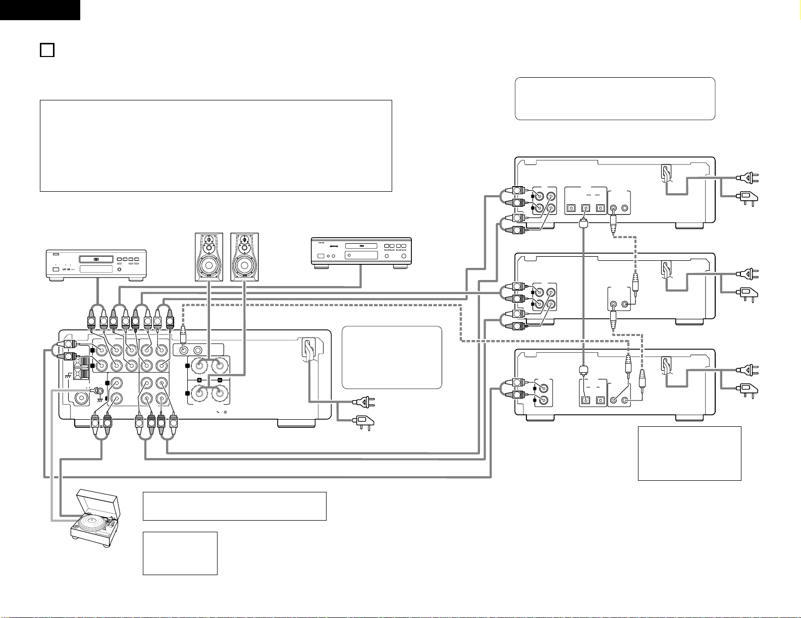
CONNECTIONS
2 When connecting, also refer to the manuals of the other components.
2 When connecting to the 201SA series, make the system connections shown by dotted lines on the diagram below.
2 The DRA-201SA is not equipped with connection cords. Use the connection cords included with the components you are
connecting to the DRA-201SA.
NOTE:
• To allow for heat dispersal, do
not place another component
or any other object directly on
top of the DRA-201SA.
NOTE:
•
If noise is generated
when the ground wire is
connected, disconnect
the ground wire.
• When making system connections with the 201SA series, connect
the system cord to the DRA-201SA system connector (either 1 or 2).
Also interconnect the other system components in the same way.
(System connections are indicated by dotted lines on the diagram.)
• The 201SA series stereo
receiver (DRA-201SA) is
equipped with a clock and timer
function, so be sure to connect
it to a wall power outlet to
which power is supplied
constantly.
Speaker system
CD player
MD recorder
(DMD-201SA)
Cassette deck
(DRR-201SA)
CD player
(DCD-201SA)
NOTES:
• Do not plug the power cords into the power outlets until all connections have been completed.
• Check the left and right channels and be sure to interconnect them correctly (R to R, L to L).
• Plug in the power cords securely. Incomplete connections will result in noise.
• Do not clasp the connection cords together with the power cords or place them near other electric products. Doing so may
result in noise.
• The PHONO input jack is extremely sensitive. A booming sound may be produced from the speakers if the volume is turned
up when no turntable is connected.
• The sound of another component may be heard if no component is connected to the input jacks of the function selected
with the FUNCTION selector.
DVD player
Power cord
(for U.K. model)
Power plug
AC 230V, 50 Hz
(Plug into a power
outlet)
Power cord
(for U.K. model)
Power plug
AC 230V, 50 Hz
(Plug into a power
outlet)
Power cord
(for U.K. model)
Power plug
AC 230V, 50 Hz
(Plug into a power
outlet)
Power cord
(for U.K. model)
Power plug
AC 230V, 50 Hz
(Plug into a power outlet)
Turntable
(with MM cartridge)
NOTE:
•
This unit cannot be used with MC cartridges directly. Use a head
amplifier or a step-up transformer with MC cartridges.
Page 7
7
ENGLISH
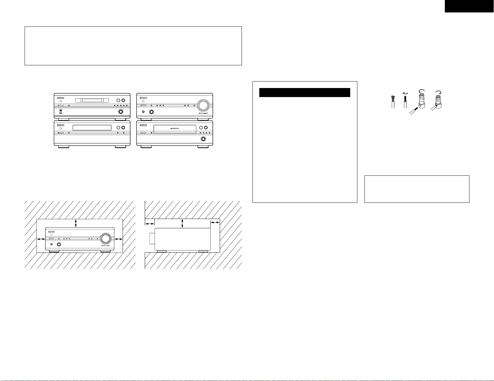
System Operations
• System operations such as the timer recording/playback and auto power on functions can only be used if stereo
audio cords and system cords are connected between all the system components. Be sure to securely connect all
the connection cords between all the units.
• Disconnecting a system cord during system operation may result in malfunction. Be sure to unplug the power
cords before changing the connections.
2
Recommended System Installation
• To ensure performance and stability, install the system (201SA series) as shown below.
1 3 2
5
ON / STANDBY
C
8/67/9
TRACK
INDEX
TIME
M
S
COMPACT DISC PLAYER DCD-201SA
ON / STANDBY
1 3 2
5
CD SRSINPUT
MEMO REC /
CHARACTER
EDIT MULTI REC
REC LEVEL / ENTER
8
9
+
MINIDISC RECORDER DMD-201SA
POWER LOADING MECHANISM
ON / STANDBY
12
5
-60 -40 -30 -20 -12 -6 -2 0
L
dB
R
3
DOLBY NR B
DOLBYNRREVERSE
/ RESET
CD SRS
REC LEVEL /
0 1
8
6
9
7
+
STEREO CASSETTE TAPE DECK DRR-201SA
4 REC
/ REC MUTE
CH
MHz
TUNED STEREO AUTO
TIMER
BAND
/ RDS
MEMORY
/ SET
DOWN UP
PRESET / TUNING
PHONES FUNCTION
VOLUME
SOURCE DIRECT
MODEON / STANDBY
STEREO RECEIVERER DRA-201SA
✽
Do not place another component directly on top of the DRA-201SA. To allow for heat dispersal, leave a space of at
least 10 cm above the DRA-201SA so as not to obstruct its ventilation holes.
✽
For stability, do not stack more than three components on top of each other.
(DRR-201SA)
(DMD-201SA)
(DCD-201SA)
Connecting Speaker Systems
2
Speaker impedance
Use speaker systems with an impedance of 4 to
16Ω/ohms.
• Note that using speakers with other impedances will
activate the protector circuit and may result in
damage.
qw e r
(DRA-201SA)
The DRA-201SA is equipped with a high
speed protector circuit.
This circuit prevents strong currents
from being generating inside the unit
and damaging internal circuitry if the
speaker cables are not securely
connected to the speaker terminals or if
they are short-circuited. If the protector
circuit is activated, the speaker output is
automatically cut off. If this happens,
turn off the unit’s power, check the
speaker cable connections, then turn the
power back on. The sound will be muted
for several seconds, after which the unit
will operate normally.
Protector Circuit
2
Connecting the speaker cords
q Peal off the coating from the tip of the cord.
w Twist the core wire.
e Turn the speaker terminal counterclockwise to
loosen it.
r Completely insert the core wire, then turn the
terminal clockwise to tighten it.
B Be sure to connect the speaker cords to the terminals
with the same polarities on the speaker and amplifier
( < to <, > to > ).
B When connecting, make sure that the speaker cords’
core wires do not stick out and touch other terminals,
other core wires or the rear panel.
NOTE:
• NEVER touch the speaker terminals while the set is
connected to a power supply. Doing so may result in
electric shock.
For heat dispersal, leave at least 10 cm of space between the top, back and sides of this unit and the wall or
other components.
CH
MHz
TUNED STEREO AUTO
TIMER
BAND
/ RDS
MEMORY
/ SET
DOWN UP
PRESET / TUNING
PHONES FUNCTION
VOLUME
SOURCE DIRECT
MODEON / STANDBY
STEREO RECEIVERER DRA-201SA
• Switching the input function when input jacks are
not connected
A clicking noise may be produced if the input function
is switched when nothing is connected to the input
jacks. If this happens, either turn down the VOLUME
control or connect components to the input jacks.
Please be sure to unplug the cord when you leave
home for, say, a vacation.
5 cm
10 cm or more
✽
✽
✽
✽
✽
Page 8

8
ENGLISH
5
PART NAMES AND FUNCTIONS
(1) Front Panel
q
Power operation switch (ON/STANDBY)
• (This turns the power for the entire system on and
off.)
• Press this once to turn the power on, then press
again to set the power to STANDBY mode.
• The LED color changes as follows, according to
the condition:
During power ON : green
During STANDBY : red
During TIMER STANDBY: orange
✻The muting mode is set when the main unit’s
power button is pressed and when the standby
mode is canceled from the remote control unit.
The power indicator flashes green when in the
muting mode, then stops flashing and turns green
once the set is in the operational mode.
✻If the indicator is flashing orange (quickly):
The protective circuit is activated.
If this happens, unplug the power cord to turn the
indicator off, then check the input and output
terminals on the rear panel. Check in particular for
short-circuiting of the speaker cords. Once all
connections have been corrected, plug the power
cord. (Wait for at least 10 seconds after turning
the power off before turning it back on.)
• When the DRA-201SA is connected in a system
with the 201SA series, its power button works as
the power button for the entire system. When
the DRA-201SA’s power turns on, the power of all
the connected system units also turns on.
✻Power is supplied to the DRA-201SA even when
the power is in the standby mode (low power
consumption).
w
Headphones jack (PHONES)
• Use this jack to listen to the sound over
commercially available headphones.
• When the headphones’ plug is inserted into the
jack, the speaker output is automatically cut off,
so no sound is produced from the speakers.
e
REMOTE SENSOR (Remote Control Sensor)
• Point the included remote control unit (RC-906) at
this sensor when operating it.
r
Function dial (FUNCTION)
• Switches the input function. Also used to set the
modes selected with the mode button.
(See pages 12, 13.)
t
Mode button (MODE)
• Use this to set the bass, treble and balance level.
(Refer to pages 12, 13.)
• Use this to set the loudness function to on or off.
(Refer to page 13.)
• Use this to set the speaker system. (Refer to
page 13.)
y
Timer button (TIMER)
• Press this button during power ON mode to
confirm or change the display. Each time this
button is pressed, the display changes as follows:
Clock: Indicates the current time.
Timer Standby: Indicates the timer standby mode.
Use the PRESET/TUNING buttons to set the timer
standby mode on or off (refer to page 17).
• Press this buttons for at least 3 seconds to set the
timer (refer to page 16) or to confirm the timer
contents (refer to page 17).
Each time the PRESET/TUNING button is pressed,
the display changes as follows:
Frequency Clock Timer Standby
TIME EVERYDAY ONCE
TIME: Use this to set the time.
EVERYDAY: Use this to set the everyday timer.
ONCE: Use this to set the once timer.
• Press this button during in STANDBY mode to
switch ON/OFF (“Saving Energy Mode”) the clock
display.
u
Band/RDS button (BAND/RDS)
• Each time this button is pressed, the band and FM
reception mode change as follows.
RDS PTY TP
FM AUTO FM MONO AM
• When the FM band, press this button for at least
3 seconds to select RDS search modes.
Each time this button is pressed, the display
changes as follows:
i
Memory/set button (MEMORY/SET)
• Use this as the memory button when presetting
AM and FM stations.
• Use this as the set button when setting the time
and timer and when inputting data.
• When the PTY search mode, press this button to
select the type of program.
• Press this button for at least 3 seconds to change
the function of the PRESET/TUNING buttons
(Preset mode or Tuning mode).
o
Display
Refer to page 9.
!0
Preset/Tuning buttons
(PRESET/TUNING UP AND DOWN)
• Use these buttons to call out the preset stations.
(PRESET UP DOWN) (See page 14.)
• Use these buttons to tune in AM and FM stations.
(TUNING UP/DOWN) (See page 13.)
!1
Source direct button (SOURCE DIRECT)
• When pressed and set to the “ON” position, the
signals bypass the tone control (bass, treble,
balance and loudness) circuits and are input
directly to the volume circuit, resulting in higher
quality sound.
• When pressed again and set to the “ OFF”
position, the signals pass through the tone control
circuits, so the tone (bass, treble, balance and
loudness) can be adjusted as desired.
!2
Volume control dial (VOLUME)
• Use this to adjust the overall volume. (Rotary
Encoder System).
• The volume increases when the control is turned
clockwise (, ), decreases when it is turned
counterclockwise (.).
• The volume increases and decreases in 70 steps
from the minimum (VOLUME 0) to the maximum
(VOLUME MAX).
!3
FM antenna terminal
(ANTENNA TERMINAL FM)
• Connect the FM antenna here.
!4
SIGNAL GND (ground) terminal
• Connect the turntable’s ground wire here.
!5
INPUT terminals (INPUTS)
These are input terminals for CD player, turntable,
DVD or other playback components.
• AUX-2:
Use these to connect a video deck or other
component.
!6
TAPE and MD REC terminals (REC)
• Recording terminals (REC)
• These are output jacks for recording.
• TAPE:
Use these to connect a cassette deck.
• MD:
Use these to connect an MD recorder
!7
Power cord
• Plug this cord into a wall power outlet.
!8
Speaker terminals
(SPEAKER SYSTEM)
• Use these to connect the speakers.
!9
System connectors
(SYSTEM CONNECTOR 1 and 2)
• When connecting the 201SA series in a system,
connect these connectors to system connectors
on other system components.
(Use the system cords included with the other
components.)
@0
TAPE and MD PLAY terminals (PB)
• Playback terminals (PB)
@1
AM antenna terminal
(ANTENNA TERMINAL AM)
• Connect the AM antenna here.
(2) Rear Panel
NOTE:
• This terminal is designed to reduce noise
when a turntable is connected.
This is not a safety ground.
Page 9
9
ENGLISH
(3) Display [o]
@3 Preset number display
• The preset number is displayed here.
@4
Main display section
• The function, input program source, etc., are
displayed here.
• During normal operation the input program source
is displayed.
• When the mode button is pressed, the display
switches to show the various functions.
• The reception band, reception frequency, time,
timer setting times, etc., are displayed here.
@2
Mode indicators
• These indicate the various modes.
• :
This lights when the timer is set to the standby
mode. It does not light if the current time and
the timer have not been set.
• TIME:
This lights when the display is set to the time
display.
• TIMER:
This lights when the timer is set.
It also lights while the timer is being set.
• ON:
This lights when the timer on time is set.
• OFF:
This lights when the timer off time is set.
• TUNED:
This lights when a station is properly tuned in.
• STEREO:
This lights in the AUTO mode when a stereo
broadcast is tuned in.
• MONO:
This lights in the AUTO mode when a monaural
broadcast is tuned in and when the MONO
mode is set with the BAND button.
• AUTO:
This lights when the AUTO mode is set with the
BAND button.
• MEMO:
This flashes when storing AM and FM stations
in the preset memory to indicate that the station
can be stored in the memory.
• SLEEP:
This lights when the sleep timer is activated.
• RDS (Radio Data System):
When the RDS button is pressed, a station is
searched for and automatically tuned in, the
“RDS” indicator lights and the station’s name is
displayed on the frequency display.
• PS (Program Service Name):
This lights when the station name is displayed.
• TP (Traffic Program):
“TP” lights when an RDS traffic information
station is received.
• PTY (Program Type):
This indicator lights when the type of RDS
program is specified.
• RT (Radio Text):
“RT” lights when a station offering radio text
services is tuned in.
2 The included remote control unit (RC-906) can be used to perform the main operations of the units in the 201SA
series that are connected with system connections. Other components cannot be operated with this remote control
unit.
Note that some functions may not operate with system remote control units. In this case, use the remote control unit
included with the component.
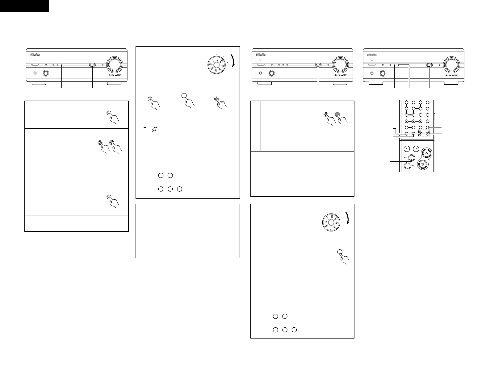
6
SYSTEM REMOTE CONTROL
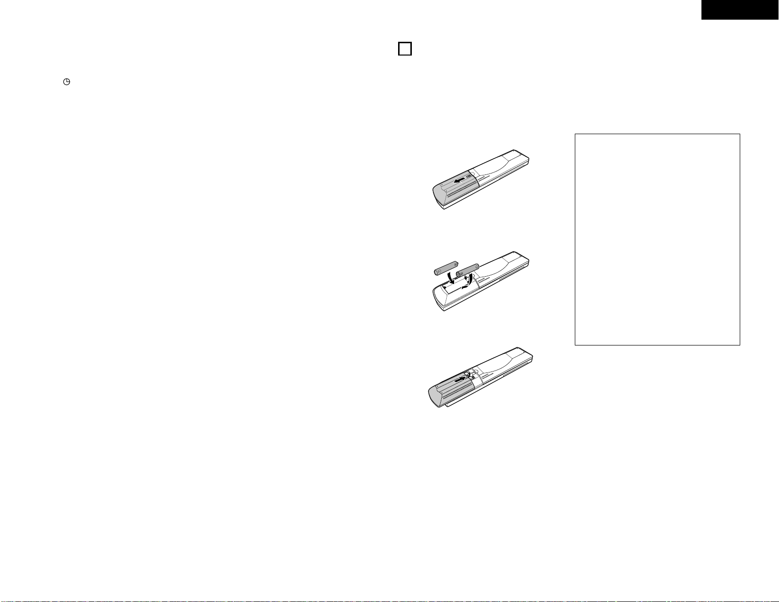
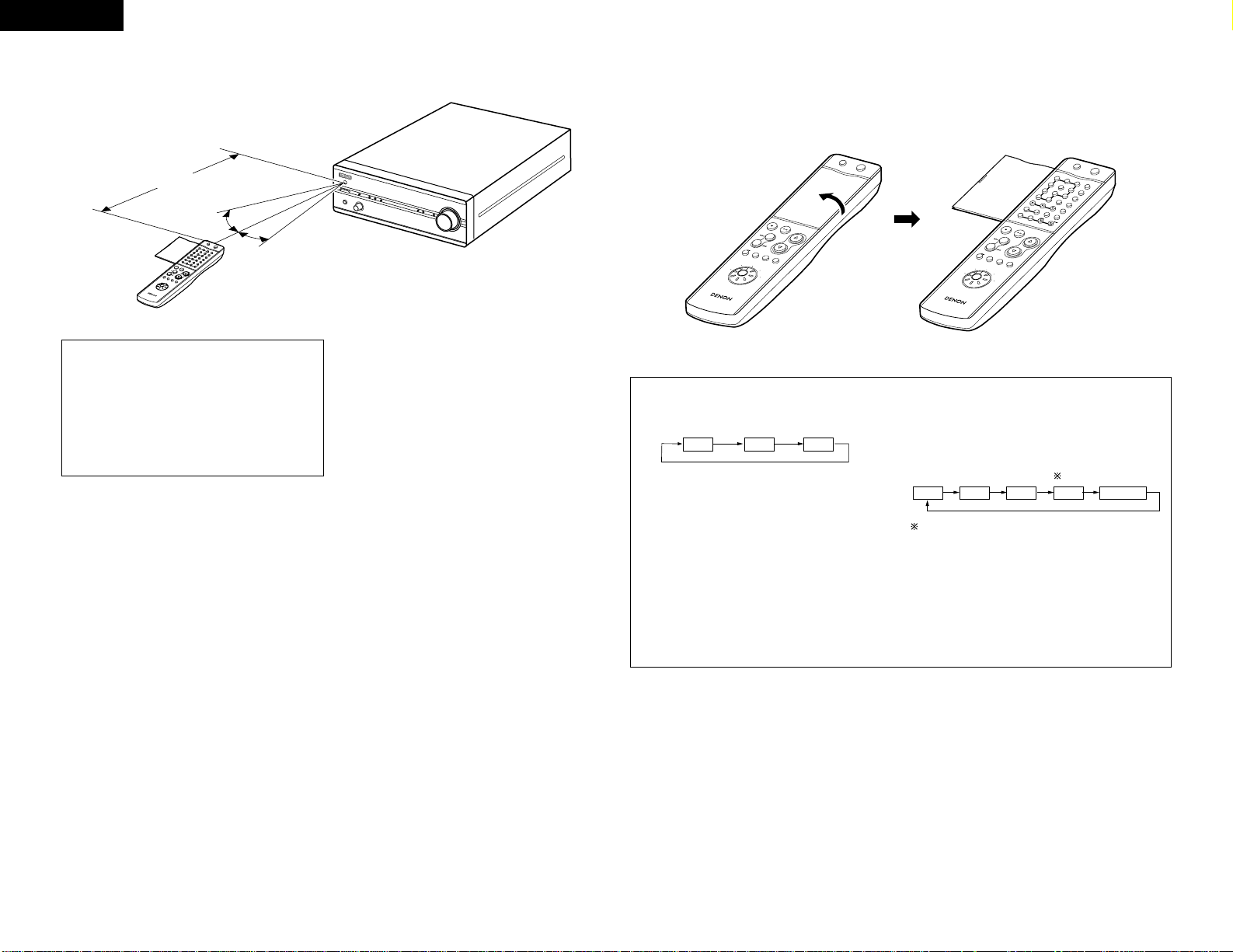
(1) Inserting Batteries
q Remove the remote control unit’s cover.
w Insert two R03 (AAA) batteries into the battery
compartment in the direction indicated by the marks.
e Set the cover back in its original position.
Cautions on Batteries
• Use R03 (AAA) batteries in this remote control unit.
• Replace the batteries with new ones after
approximately 1 year, though this depends on the
frequency with which the remote control unit is
used.
• Replace the batteries with new ones if the unit does
not operate when the remote control unit is
operated from nearby, even if the batteries are less
than a year old.
• Be sure to insert the batteries in the proper
direction, following the “ < ” and “ > ” marks in
the battery compartment.
• To avoid damage or leakage of battery fluid:
• Do not use a new battery with an old one.
• Do not use two different types of batteries.
• Do not short-circuit, take apart, heat or dispose of
batteries in flames.
• Remove the batteries when you do not plan to use
the remote control unit for an extended period of
time.
• If the battery fluid should leak, carefully wipe off the
fluid from the inside of the battery compartment,
then insert new batteries.
Page 10
10
ENGLISH
(2) Using the Remote Control Unit
• Point the remote control unit at the remote sensor on
the main unit as shown on the diagram when operating
it.
(When system connections are made, the remote
control signals for all the system components are
received at the DRA-201SA remote sensor.)
• The remote control unit can be used from a straight
distance of about 7 meters, but this distance will be
shorter if the there is an obstacle in the way or if the
remote control unit is not pointed directly at the remote
sensor.
• Use the remote control unit within a range of 30° to the
left and right of the remote sensor.
RC
-906
R
E
M
O
T
E
C
O
N
T
R
O
L
U
N
I
T
C
L
E
A
R
5
5
+1
0
C
D
S
R
S
M
D
T
A
P
E
C
D
R
T
U
N
I
N
G
R
E
V
.
M
O
D
E
D
o
l
b
y
N
R
R
E
P
E
A
T
C
A
L
L
P
R
O
G
/
D
I
R
E
C
T
R
A
N
D
O
M
B
A
N
D
R
D
S
D
I
M
M
E
R
T
I
M
E
/
P
A
N
E
L
T
I
M
E
E
D
I
T
S
Y
S
T
E
M
P
O
W
E
R
O
F
F
O
N
S
T
O
P
P
L
A
Y
V
O
LU
ME
/
S
E
L
E
C
T
S
L
E
E
P
M
O
D
E
T
A
P
E
F
U
N
C
T
I
O
N
P
R
E
S
E
T
+
-
T
U
N
E
R
C
D
C
D
R
M
D
T
A
P
E
1
2
3
4
6
7
8
9
+
-
10
+1
0
Approx. 7m
30°
30°
NOTES:
• The remote control unit may not work properly if the
remote sensor is exposed to direct sunlight or
strong artificial light or if there is an obstacle
between the remote control unit and the remote
sensor.
• Do not press the buttons on the main unit and the
remote control unit at the same time. Doing so will
result in malfunction.
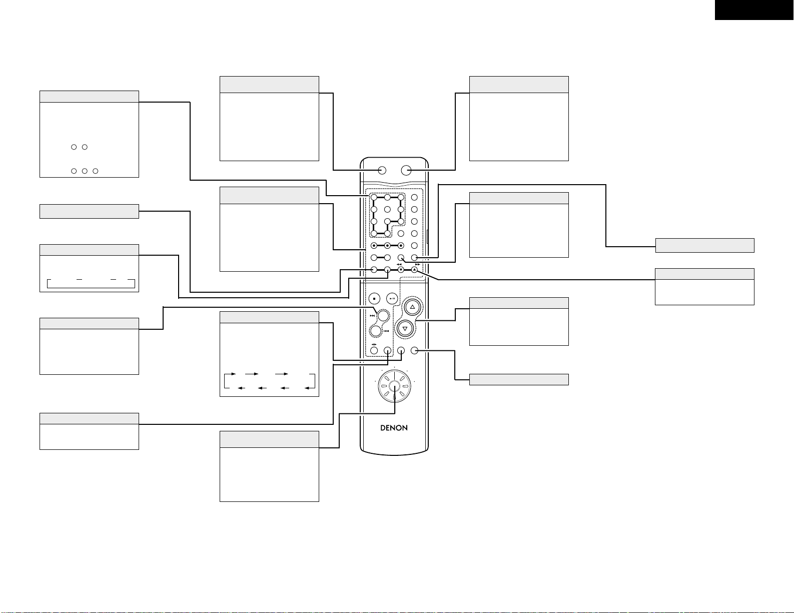
(3) Names and Functions of Remote Control Unit Buttons
2
Opening the remote control unit’s cover
R
C
-
9
0
6
REMOTE CONTROL UNIT
CLEAR
5
5
C
D
S
R
S
M
D
T
A
P
E
C
D
-
R
TUNING
R
E
V
.
M
O
D
E
D
O
L
B
Y
REPEAT
CALL
P
R
OG
/
D
IR
E
C
T
RANDOM
BAND
PTY
RDS
DIMMER
TIME/
PANEL
TIME EDIT
SYSTEM
POWER
O
FF
O
N
STOP
PLAY
V
O
L
U
M
E
/SELECT
SLEEP
MODE
TAPE
F
U
N
C
T
I
O
N
PRESET
+
-
TUNER
CD
CD-R
MD
TAPE
+
-
1
23
6
4
7
8
9
+
1
0
0
R
C
-
9
0
6
REMOTE CONTROL UNIT
CLEAR
5
5
C
D
S
R
S
M
D
T
A
P
E
C
D
R
TUNING
R
E
V
.
M
O
D
E
D
O
L
B
Y
REPEAT
CALL
P
R
O
G
/
D
IR
E
C
T
RANDOM
BAND
PTY
RDS
DIMMER
TIME/
PANEL
TIME EDIT
SYS
TEM
POW
ER
O
FF O
N
STOP
PLAY
V
O
L
U
M
E
/SELECT
SLEEP
MODE
TAPE
F
U
N
C
T
I
O
N
PRESET
+
-
TUNER
CD
CD-R
MD
TAPE
1
23
4
6
7
89
+
-
+
1
0
0
RDS button
Use this button to automatically tune to stations using
the radio data system.
PANEL button
This button is used to select the panel mode.
Press this button when receiving RDS stations to
select the frequency, PS, PTY, RT or CT display.
The display mode changes as follows each time the
button pressed.
✽Press the PRESET < or > button after selecting
“PTY” with the RDS button to select one of the 29
program type.
RDS PTY TP
PS PTY RT Frequency
CT
CT display
Use this to correct the time of the clock on the DRA201SA. Press the PANEL button when the time
service of an RDS station is being properly received.
“CT” and “TIME” are displayed and the DRA201SA’s clock is corrected. “NO CT” is displayed if
the RDS station does not offer a time service and
when the broadcast is not being received properly.
Note that this button will not function if the reception
is poor.
✽
Page 11
11
ENGLISH
RC-906
REMOTE CONTROL UNIT
CLEAR
123
546
789
10
+10
CD SRS
MDTAPECD-R
TUNING
REV.
MODE
Dolby NR
REPEAT
CALL
PROG/
DIRECT
RANDOM
BAND
RDS
DIMMER
TIME/
PANEL
TIME EDIT
SYSTEM
POWER
OFF ON
STOP PLAY
VOLUME
/SELECT
SLEEP MODE
TAPE
FUNCTION
PRESET
+
-
TUNER
CD
CD-R
MD
TAPE
Models compatible with system remote control
• Receiver : DRA-201SA
• CD player : DCD-201SA
• Cassette deck : DRR-201SA
• MD recorder : DMD-201SA
Press this to set the DRA201SA’s power to the standby
mode.
(When connected in a system
with the 201SA series, this
button sets the power of the
entire system to the standby
mode.)
Power standby button
(SYSTEM POWER STANDBY)
When connected in a system
with the 201SA series, these
buttons are used to operate the
various connected system
components.
For operating instructions, refer
to the manuals of the various
components.
201SA series
function operation block
Press this to select the function
source to be played.
The function switches in the
following order each time the
button is pressed:
FUNCTION button
Use this to select the function to
be operated with this remote
control unit. For instructions on
operating the various
components, refer to their
respective manuals.
Remote control
function selector switch
When this button is pressed
while the DRA-201SA’s power is
in the standby mode, the DRA201SA’s power turns on.
(When connected in a system
with the 201SA series, this
button turns on the power of the
entire system.)
Power on button
(SYSTEM POWER ON)
• Press Dto increase the
volume,
H
to decrease it.
• These buttons are also used to
set various modes.
VOLUME/SELECT buttons
CD
MD TAPE AUX-2
PHONO
TUNER DVD/AUX
MODE button
2 Buttons not described here function in the same way as the corresponding buttons on the main unit.
The display becomes darker (in 4
steps) each time this button is
pressed.
Adjust the brightness of the
display according to the
brightness of the room.
DIMMER button
✽The buttons above for which there are no explanations cannot be operated with the DRA-201SA.
Press these buttons to recall
preset station.
Examples:
To call the station at preset
number 12:
Press ,
To call the station at preset
number 29:
Press , ,
9
+10
+102+10
Number buttons
RDS button (RDS)
Use this button to selecting the
band.
BAND button (BAND)
FM AUTO FM MONO AM
Use these buttons to recall preset
stations on the tuner.
Press this button after selecting
“PTY” with RDS button to select
one of the 29 program types.
PRESET button (PRESET)
Press this button to set the sleep
timer
SLEEP button (SLEEP)
PANEL button (PANEL)
Use these buttons to selecting
the station.
TUNING button (•,ª)
Page 12
12
ENGLISH
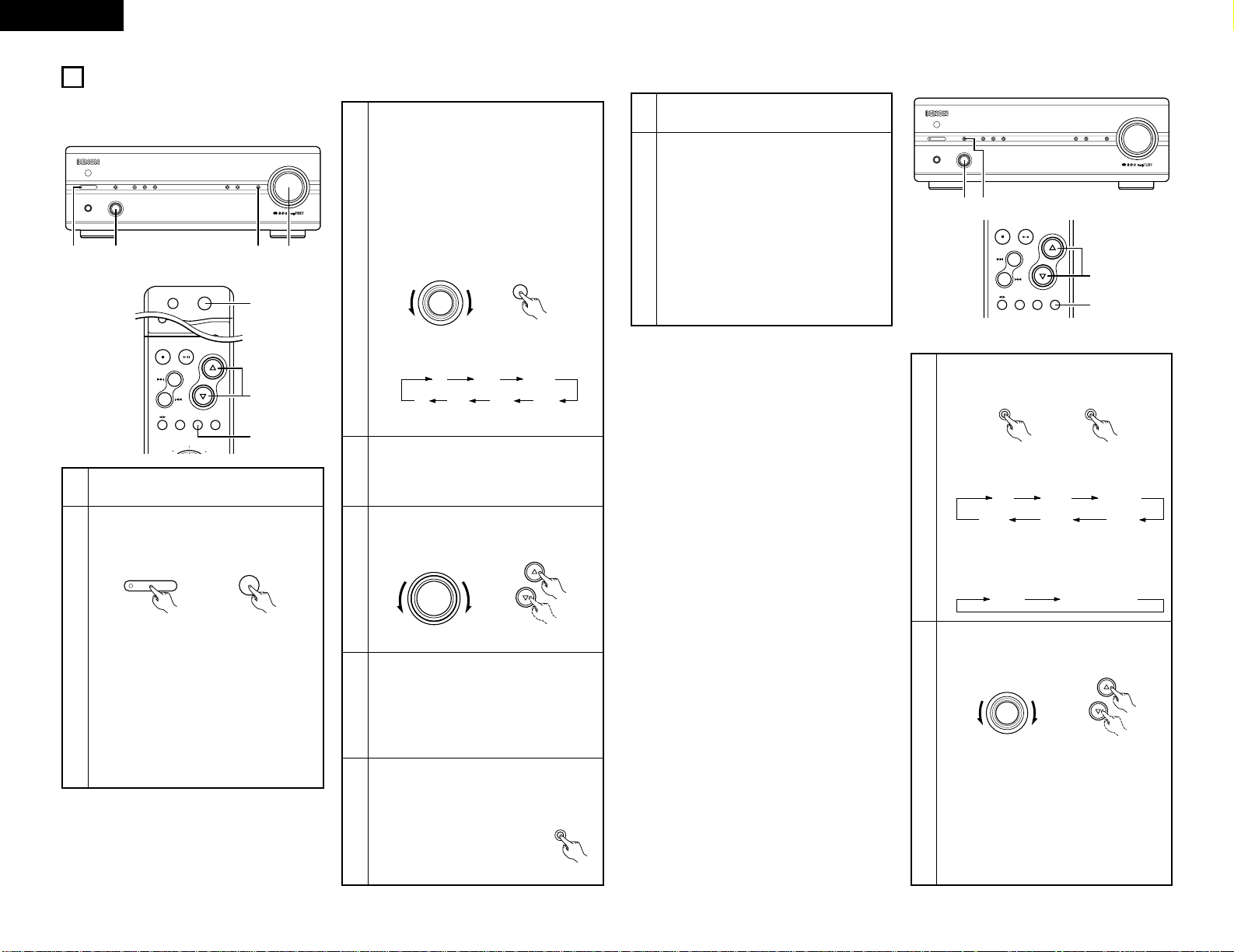
7
OPERATION
(1) Playback
CH
MHz
TUNED STEREO AUTO
TIMER
BAND
/ RDS
MEMORY
/ SET
DOWN UP
PRESET / TUNING
PHONES FUNCTION
VOLUME
SOURCE DIRECT
MODEON / STANDBY
STEREO RECEIVERER DRA-201SA
3 7 52
123
PROG/
DIRECT
SYSTEM
POWER
OFF ON
2
PTY
STOP PLAY
VOLUME
/SELECT
SLEEP MODE
TAPE
FUNCTION
PRESET
+
-
TUNER
CD
MD
3
5
3
Either turn the FUNCTION dial on the main unit
or press the remote control unit’s FUNCTION
button to select the function source to be
played.
• The function switches in the order shown
below.
✽
The function switches in the opposite order
when the dial is turned counterclockwise (.).
CD
MD TAPE AUX-2 PHONO
TUNER DVD/AUX
(Main unit) (Remote control unit)
4
Start playback of the selected function source.
• For instructions on operation, refer to the
component’s operating instructions.
5
Adjust the volume.
6
Adjust the BALANCE, BASS, and TREBLE
controls and set the LOUDNESS position to the
desired position.
✽
For instructions on adjusting, see “(3) Setting
the various modes” on page 12, 13.
7
To use the source direct function:
Set the SOURCE DIRECT button to the “ON”
position.
VOLUME
VOLUME
/SELECT
(Main unit) (Remote control unit)
(Main unit)
1
Check that all connections are correct.
2
Turn on the power.
• The indicator first flashes red, then turns
green and stops flashing (remaining lit).
(Main unit)
ON / STANDBY
SYSTEM
POWER
ON
(Remote control unit)
2 Power on/standby mode and function
memory
B
When the remote control unit is used to
turn the DRA-201SA’s power on from the
standby mode, the function is set to the
function that was selected when the
power was last set to the standby mode.
(Last memory function)
B
If the function has been cleared from the
memory, the function is set to “CD” when
the DRA-201SA’s power is turned on.
(3) Setting the various modes
[1] Adjusting the bass and treble
CH
MHz
TUNED STEREO AUTO
TIMER
BAND
/ RDS
MEMORY
/ SET
DOWN UP
PRESET / TUNING
PHONES FUNCTION
VOLUME
SOURCE DIRECT
MODEON / STANDBY
STEREO RECEIVERER DRA-201SA
2 1
STOP PLAY
VOLUME
/SELECT
SLEEP MODE
TAPE
FUNCTION
PRESET
+
-
1
2
1
2
Press the MODE button to display the mode to
be adjusted (“BASS” or “TREBLE”).
Either turn the FUNCTION dial on the main unit
or use the remote control unit’s SELECT
buttons.
BASS
Playback
function source
SPEAKER BALANCE
TREBLE LOUDNESS
SPEAKER
Playback function source
(Main unit)
MODE
(Remote control unit)
FUNCTION
VOLUME
/SELECT
(Main unit) (Remote control unit)
• To increase the bass or treble:
Turn the dial clockwise (,) or press the
D
button.
To decrease the bass or treble:
Turn the dial counterclockwise (.) or press
the
H
button.
• The bass and treble can be adjusted within
the range of –12 to 0 to +12 in steps of 2.
The response is flat at 0.
• The mode switches as follows each time the
button is pressed:
✽
When the source direct mode is on, the mode
switches as shown below (the BASS and
TREBLE adjustment modes cannot be
selected).
(decrease) (increase)
(decrease)
(increase)
SOURCE DIRECT
(2) Recording
1
Follow step 1 to 4 under “(1) Playback”.
2
Start recording on the cassette deck or MD
recorder.
For instructions, refer to the component’s
operating instructions.
• Operating the VOLUME, BALANCE, BASS,
TREBLE and the LOUDNESS controls will not
affect the sound being recorded.
• When the function source is set to “MD”,
recording is performed from the MD recorder
onto the cassette deck. When the function
source is set to “TAPE” , recording is
performed from the cassette deck onto the
MD recorder.
FUNCTION
FUNCTION
MODE
Page 13
13
ENGLISH
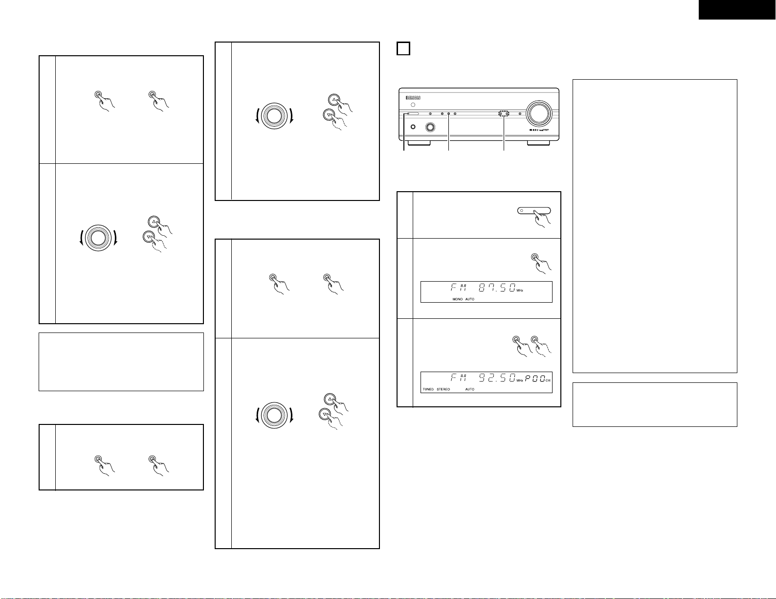
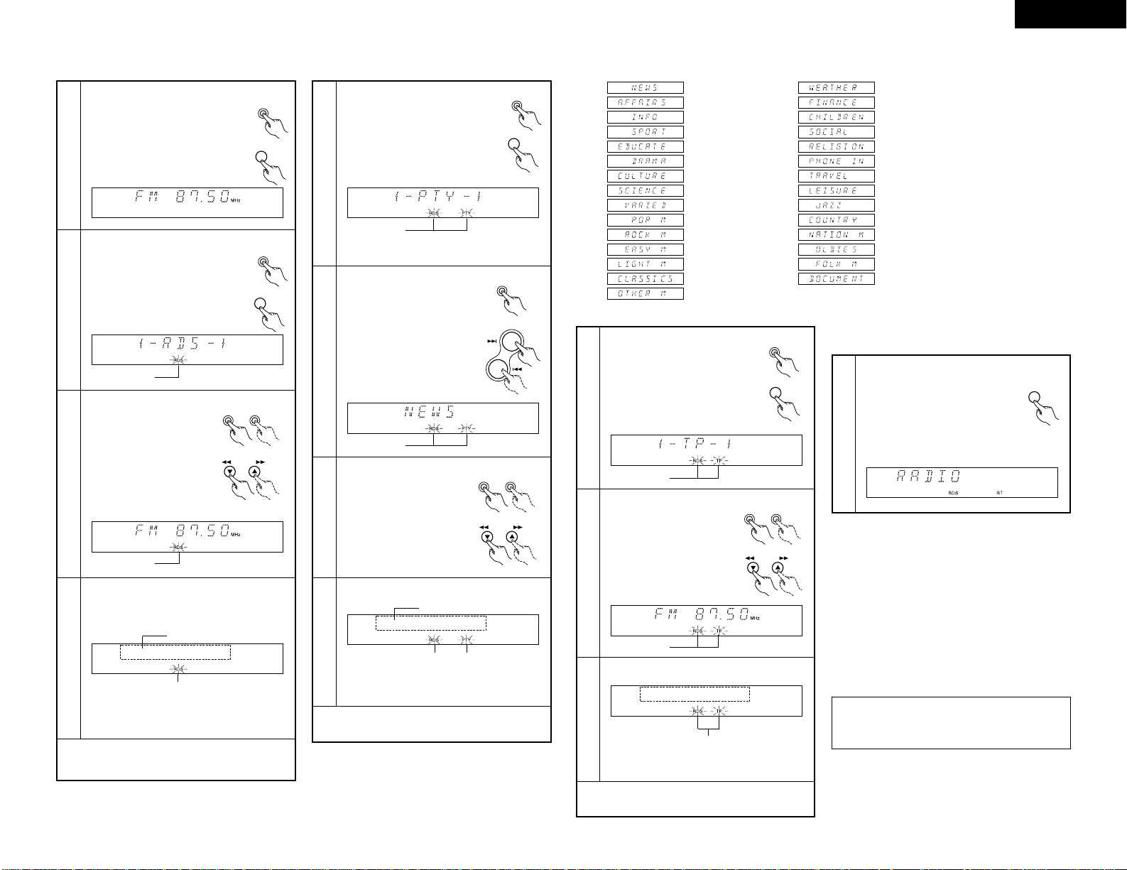
8
LISTENING TO RADIO
(1) Tuning
1
Press the power operation
switch to turn on the power.
2
3
Press the BAND/RDS button on
the tuner to select the FM AUTO.
Use the PRESET/TUNING
UP/DOWN button to tune
the frequency to 92.50.
CH
MHz
TUNED STEREO AUTO
TIMER
BAND
/ RDS
MEMORY
/ SET
DOWN UP
PRESET / TUNING
PHONES FUNCTION
VOLUME
SOURCE DIRECT
MODEON / STANDBY
STEREO RECEIVERER DRA-201SA
2 31
ON / STANDBY
BAND
/ RDS
DOWN UP
PRESET / TUNING
Example: Tuning in FM 92.50 MHz
(AM stations are tuned in using the same procedure.)
This lights when a station is tuned in.
✽
The function of the UP/DOWN button on the main
unit may toggle between TUNING UP/DOWN and
PRESET UP/DOWN functions.
• Press the MEMORY/SET button for at least 3
seconds. Then press the UP button.
The function of the UP/DOWN buttons are changed
to TUNING UP/DOWN.
• Press the MEMORY/SET button for at least 3
seconds. Then press the DOWN button. The
function of the UP/DOWN buttons are changed to
PRESET UP/DOWN.
• The UP/DOWN button is factory preset to function
as a TUNING UP/DOWN button.
However, be sure that the UP/DOWN buttons
function as the TUNING UP/DOWN button before
proceeding with step 3.
Auto Tuning
• When a program being broadcast in stereo is
received, the “STEREO” indicator lights and the
program is received in stereo.
• If reception is poor and there is much noise in the
stereo signals, press the BAND button to set the FM
MONO mode.
• When one of the TUNING UP/DOWN button is
pressed, the frequency changes in steps of 50 kHz in
the FM band, 9 kHz in the AM band.
• If one of the TUNING UP/DOWN button is held for
over 1 second, the frequency continues to change
when the button is released (auto tuning) and stops
when a station is tuned in. Tuning will not stop at
stations whose reception is poor.
• To stop the auto tuning function, press the TUNING
UP/DOWN button once.
NOTE:
A humming sound may be heard when using a TV
nearby while receiving AM programs. If this happens,
move the system as far from the TV as possible.
[2] Setting the loudness mode
1
2
Press the MODE button to display
“LOUDNESS”.
Either turn the FUNCTION dial on the main unit
or use the remote control unit’s SELECT
buttons.
MODE
(Main unit)
MODE
(Remote control unit)
FUNCTION
VOLUME
/SELECT
(Main unit) (Remote control unit)
• To set to “ON”:
Turn the dial clockwise (,) or press the
D
button.
To set to “OFF”:
Turn the dial counterclockwise (.) or press
the
H
button.
• The mode switches as shown at the left each
time the button is pressed.
✽
“LOUDNESS” cannot be selected when the
source direct mode is on.
(OFF) (ON)
(ON)
(OFF)
NOTE:
The maximum total volume increase for the bass,
treble and loudness together is +12. If for example
the bass and treble are set to +12, the sound does
not change when the loudness function is turned on
and off.
[3] Setting the speaker mode
1
Press the MODE button to display “SPEAKER”.
(Refer to page 12.)
MODE
(Main unit)
MODE
(Remote control unit)
2
Either turn the FUNCTION dial on the main unit
or use the remote control unit’s SELECT
buttons.
FUNCTION
VOLUME
/SELECT
(Main unit) (Remote control unit)
• To set to “ON”:
Turn the dial clockwise (,) or press the
D
button.
To set to “OFF”:
Turn the dial counterclockwise (.) or press
the
H
button.
(OFF)
(ON)
(OFF)
(ON)
[4] Adjusting the balance
1
2
Press the MODE button to display “BALANCE”
(Refer to page 12.)
Either turn the FUNCTION dial on the main unit
or use the remote control unit’s SELECT
buttons.
MODE
(Main unit)
MODE
(Remote control unit)
FUNCTION
VOLUME
/SELECT
(Main unit) (Remote
control unit)
• If the volume of the right speaker is low:
Turn the dial clockwise (,) or press the
D
button.
If the volume of the left speaker is low:
Turn the dial counterclockwise (.) or press
the
H
button.
• The balance can be set to “ CENTER” or
adjusted within the range of +1 to +10 in
steps of 1. When set “CENTER” , the
difference between the volume of the left and
right speakers is 0.
✽
“BALANCE” cannot be selected when the
source direct mode is on.
(left channel
volume
adjustment)
(right
channel
volume
adjustment)
(left channel
volume
adjustment)
(right
channel
volume
adjustment)
Page 14
14
ENGLISH
(2) Presetting AM and FM stations
Example: To preset the currently tuned in FM station at preset number “3”
Procedure
1
Press the MEMORY/SET button.
• The “ MEMO” indicator
flashes.
✽
To store the station at a different preset
number, use the tuning buttons
(PRESET/TUNING UP or DOWN) to set the
desired preset number.
2
While the “MEMO” indicator
is flashing, press the
PRESET/TUNING UP button
three times to display “P3”.
Press the MEMORY/SET button
again while the “MEMO”
indicator is flashing.
• The “MEMO” indicator turns
off and the station is preset.
3
✽
A total of 40 AM and FM stations can be preset
using this procedure.
Presetting
• When a station is preset, both the reception
frequency and reception mode are stored in the
memory.
• If a station is preset at a number where another
station is already preset, the previous station is
erased and the new station is set.
• The preset memory is not erased immediately if the
power supply is cut off momentarily.
• This setting can also be made by pressing the
button three times instead of pressing
“e”.
• To store the station at a different preset number,
use the number buttons and the +10 button on the
system remote control unit (RC-906) to set the
desired preset number.
Examples:
To store the station at preset number 12:
Press ,
To store the station at preset number 29:
Press , ,
9
+10
+102+10
TUNING
CH
MHz
TUNED STEREO AUTO
TIMER
BAND
/ RDS
MEMORY
/ SET
DOWN UP
PRESET / TUNING
PHONES FUNCTION
VOLUME
SOURCE DIRECT
MODEON / STANDBY
STEREO RECEIVERER DRA-201SA
1, 3 2
DOWN UP
PRESET / TUNING
MEMORY
/ SET
MEMORY
/ SET
MEMORY
/ SET
MEMORY
/ SET
3
//
DRA-201SA
(this unit)
DRA-201SA
(this unit)
(RC-906)
✽
When operating with the
system remote control unit,
first set the remote control
unit’s function selector switch
to “TUNER”.
TUNER
CD
CD-R
MD
TAPE
(RC-906)
(3) Tuning in Preset Stations
Example: To tune in the station stored at preset
number “3”
1
Press the PRESET UP
button three times to display
“P3”.
CH
MHz
TUNED STEREO AUTO
TIMER
BAND
/ RDS
MEMORY
/ SET
DOWN UP
PRESET / TUNING
PHONES FUNCTION
VOLUME
SOURCE DIRECT
MODEON / STANDBY
STEREO RECEIVERER DRA-201SA
1
DOWN UP
PRESET / TUNING
✽
Preset stations can also be called out using the
preset buttons (PRESET UP and DOWN) after a
preset number is called out.
Example:
After calling out “
P3”, press the PRESET UP button
to call out “P4”, the PRESET DOWN button to call
out “P2”.
✽
When operating with the
system remote control unit,
first set the remote control
unit’s function selector switch
to “TUNER”.
TUNER
CD
CD-R
MD
TAPE
(RC-906)
Procedure:
• Instead of pressing e, the preset
channel can also be called out by
pressing the < or > button to display
“P3”.
• To call the station at a different preset number, use
the number buttons and the +10 button on the
system remote control unit (RC-906) to set the
desired preset number.
Examples:
To call the station at preset number 12:
Press ,
To call the station at preset number 29:
Press , ,
9
+10
+102+10
3
(4)
Using the RDS functions
CH
MHz
TUNED STEREO AUTO
TIMER
BAND
/ RDS
MEMORY
/ SET
DOWN UP
PRESET / TUNING
PHONES FUNCTION
VOLUME
SOURCE DIRECT
MODEON / STANDBY
STEREO RECEIVERER DRA-201SA
1, 2, 5, 9 6 3, 7,10
CLEAR
546
789
10
+10
CD SRS
MDTAPECD-R
TUNING
REV.
MODE
Dolby NR
REPEAT
CALL
RANDOM
BAND
RDS
DIMMER
TIME/
PANEL
TIME EDIT
STOP PLAY
VOLUME
/SELECT
TAPE
PRESET
+
-
1
2,5,9
3,7,10
12
6
RC-906
(system remote
control unit)
✽
Be sure that the UP/DOWN buttons function
as the PRESET UP/DOWN buttons before
proceeding with step 1.
Page 15
15
ENGLISH
PTY Search
5
Press the RDS button twice on the
remote control unit.
BAND
/ RDS
Flashes
7
Press the PRESET/TUNING
UP or DOWN button.
DOWN UP
PRESET / TUNING
8
The station is tuned in.
Once the station is tuned in, ”RDS“ and ”PTY“
flash for 5 seconds and the program service
name is displayed.
”PTY“ and ”RDS“ light after 5 seconds of flashing.
NOTE: If no program of the specified type is
found,” NO PROG “ is displayed.
(”PTY“ and ”RDS“ flash, and ”, PTY /“ is
displayed.)
6
Press the MEMORY/SET button
to select the type of program.
Press the PRESET < or >
button on the remote control
unit to select the type of
program.
(One of the 29 types listed
below can be selected.)
MEMORY
/ SET
Flashes
Station name
Press the BAND/RDS button for at
least 3 seconds. Then press the
BAND/RDS button once.
RDS
PRESET
+
-
Press the TUNING • or ª
button on the remote control
unit.
TUNING
(News)
(Varied)
(Affairs)
(Information)
(Sport)
(Education)
(Drama)
(Culture)
(Pop Music)
(Rock Music)
(
Easy Listening
)
(Light Classics)
(Serious Classics)
(Other Music)
(Science)
Programs
TP Search
9
Press the RDS button 3 times on
the remote control unit.
11
The station is tuned in.
Once the station is tuned in, ”TP“ and ”RDS“
light and program service name is displayed.
“TP” and “RDS” light after 5 seconds of flashing.
NOTE: ” NO PROG “ is displayed when there is
traffic information broadcast station.
10
Press the PRESET/TUNING
UP or DOWN button.
DOWN UP
PRESET / TUNING
RT (Radio Text)
12
To turn the RT mode on, press the
PANEL button on the remote control
unit until the RT indicator is lit. (Refer
to page 11.)
When the station currently tuned in is
offering a radio text message service,
the message scrolls on the display.
TIME/
PANEL
• When the RT mode is turned on while an RDS radio
station not offering an RT service is tuned in, ” NO
TEXT “ flashes on the display, then the mode
automatically switches to the PS mode.
• In the same way, the mode automatically switches to
the PS mode when the RT service is finished. In this
case, the mode automatically switches from the PS
mode back to the RT mode when an RT broadcast is
resumed.
• The RT mode cannot be set in the AM band or FM
stations not offering RDS broadcasts.
• To turn the RT mode off, press the PANEL button and
switch to the desired display mode.
(This operation is only possible from the remote
control unit RC-906)
BAND
/ RDS
RDS
Press the BAND/RDS button for at
least 3 seconds.
The press the BAND/RDS button
twice.
TUNING
Press the TUNING • or ª
button on the remote
control unit.
(Weather & Meteorological)
(Jazz Music)
(Finance)
(Children's Progs)
(Social Affairs)
(Religion)
(Phone In)
(Travel & Touring)
(Country Music)
(National Music)
(Oldies Music)
(Folk Music)
(Documentary)
(Leisure & Hobby)
Flashes
Flashes
NOTE:
The PANEL function can only be operated with the
remote control unit (RC-906).
Receiving RDS broadcasts (FM only)
1
Press the BAND button on the
remote control unit and set the FM
AUTO.
BAND
/ RDS
2
Press the RDS button on the remote
control unit.
Flashes
BAND
BAND
/ RDS
RDS
Press the BAND/RDS button and set
the FM AUTO.
Press the BAND/RDS button for at
least 3 seconds.
3
Press the TUNING •or
ª
button on the remote control
unit.
DOWN UP
PRESET / TUNING
Flashes
4
The station is tuned in.
Once the station is tuned in, ”RDS“ flashes for
5 seconds and program service name is
displayed.
”RDS“ lights after 5 seconds of flashing.
NOTE: • If no RDS station is found, ” NO PROG “ is
displayed.
TUNING
Press the PRESET/TUNING
UP or DOWN button.
Station name
Page 16
16
ENGLISH
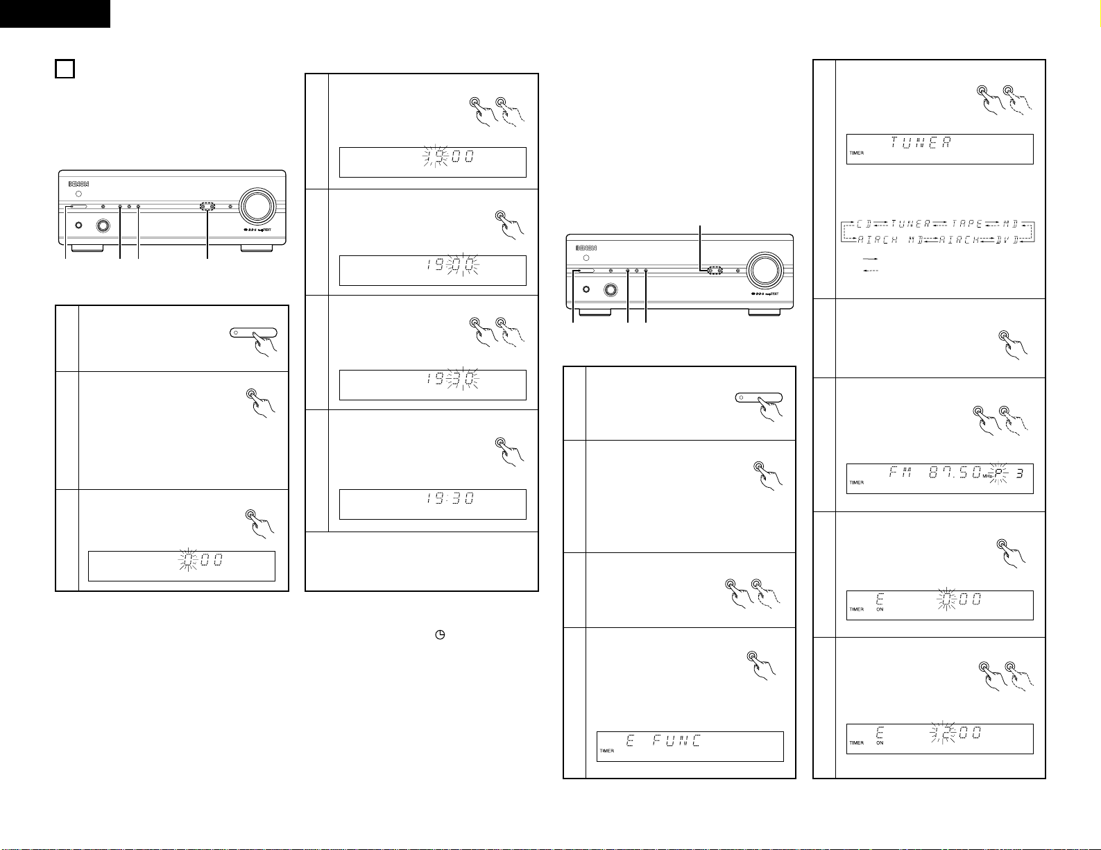
9
USING THE TIMER
(1)
Setting the Current Time (24-hour display)
Example: Setting the current time to 19:30
1
Turn on the power.
2
Press the TIMER button for at least
3 seconds.
•“TIME” is displayed.
✽
If the time is already set,
“EVERYDAY” is displayed.
Press one of the PRESET/TUNING
buttons to display “TIME”, then
perform step 3.
7
Press the MEMORY/SET button
at the sound of the chime of a
time service, etc.
•“30” stops flashing, remaining
lit, and the current time is
displayed.
✽
The number changes continuously when one of the
tuning buttons (TUNING UP or DOWN) is pressed.
✽
If the time is already set when step 2, 3 is performed,
both the hours and minutes positions flash.
MEMORY
/ SET
CH
MHz
TUNED STEREO AUTO
TIMER
BAND
/ RDS
MEMORY
/ SET
DOWN UP
PRESET / TUNING
PHONES FUNCTION
VOLUME
SOURCE DIRECT
MODEON / STANDBY
STEREO RECEIVERER DRA-201SA
2 3, 5, 7 4, 61
ON / STANDBY
TIMER
5
Press the MEMORY/SET button.
•“19” stops flashing, remaining
lit, and the minutes position
starts flashing.
MEMORY
/ SET
Use the PRESET/TUNING
buttons to input the
minutes (30).
•“30” flashes in the
minutes position.
6
DOWN UP
PRESET / TUNING
3
Press the MEMORY/SET button.
• The hours position flashes.
MEMORY
/ SET
Use the PRESET/TUNING
buttons to input the hours
(19).
•“19” flashes in the hours
position.
4
DOWN UP
PRESET / TUNING
(2) Before Setting the Timer
2 Be sure to set the current time. If the current time is not set, the timer standby indicator (“”) will not light and the
timer will not function.
2 Be sure to preset the station before setting the timer. (Refer to “Presetting AM and FM stations” on page 14.)
2 The DRA-201SA is equipped with two types of timers: the everyday time which turns the power on and off at the
same times every day, and the once timer that turns the power on and off only once.
2 Do not change the timer standby mode after the timer is activated (after the timer on time is reached). The timer may
not operate properly.
2 It is not possible to set the timer start and end times to the same time.
2 If the display or operation is not normal, unplug the power cord, then plug it back in while pressing the memory/set
button (MEMORY/SET). This restores the tuner to the initial default values. After doing this, reset the presettings,
current time and timer settings.
2 When setting the timer to operate the CD player, MD recorder or cassette deck, do so with a disc or cassette loaded
and the disc holder or cassette holder closed. The timer will not operate properly if no disc or cassette is loaded or if
the disc holder or cassette holder is open.
(3) Setting the Timer
2 The timer function lets you switch the power between
the on and standby modes automatically at the desired
times.
2 When connected in a system with the 201SA series,
the timer can be used to play a CD, cassette or MD or
to record from the tuner onto the MD recorder or
cassette deck (“air check”).
Example: Using the everyday timer to listen to the
station stored at preset number 3 (FM 98.00 MHz)
from 12:35 to 12:56
1
Turn on the power.
2
Press the TIMER button for at least
3 seconds.
•“EVERYDAY” is displayed.
TIMER
ON / STANDBY
CH
MHz
TUNED STEREO AUTO
TIMER
BAND
/ RDS
MEMORY
/ SET
DOWN UP
PRESET / TUNING
PHONES FUNCTION
VOLUME
SOURCE DIRECT
MODEON / STANDBY
STEREO RECEIVERER DRA-201SA
2
4, 6, 8,10,12,14,16
1,18
3, 5, 7, 9,11,13,15,17
✽
If the time is not set, “TIME” is displayed.
Perform steps 3 to 7 on page 16, then start
the timer setting over.
Press one of the
PRESET/TUNING buttons
to display “EVERYDAY” or
“ONCE”.
DOWN UP
PRESET / TUNING
3
4
Press the MEMORY/SET button.
• This sets the unit to the timer
setting mode’s function
setting mode.
MEMORY
/ SET
Example: When the everyday timer is
selected
5
Use the PRESET/TUNING
buttons to switch the
function to “TUNER”.
DOWN UP
PRESET / TUNING
✽
The function switches as follows each time
the button is pressed:
: When the TUNING UP button is pressed.
: When the TUNING DOWN button is
pressed.
6
Press the MEMORY/SET button.
•“TUNER” is stored in the
memory as the timer function.
MEMORY
/ SET
Use the PRESET/TUNING
buttons to set preset
number 3.
DOWN UP
PRESET / TUNING
7
8
Press the MEMORY/SET
button.
• The preset station is stored in
the memory and the timer on
time setting mode is set.
MEMORY
/ SET
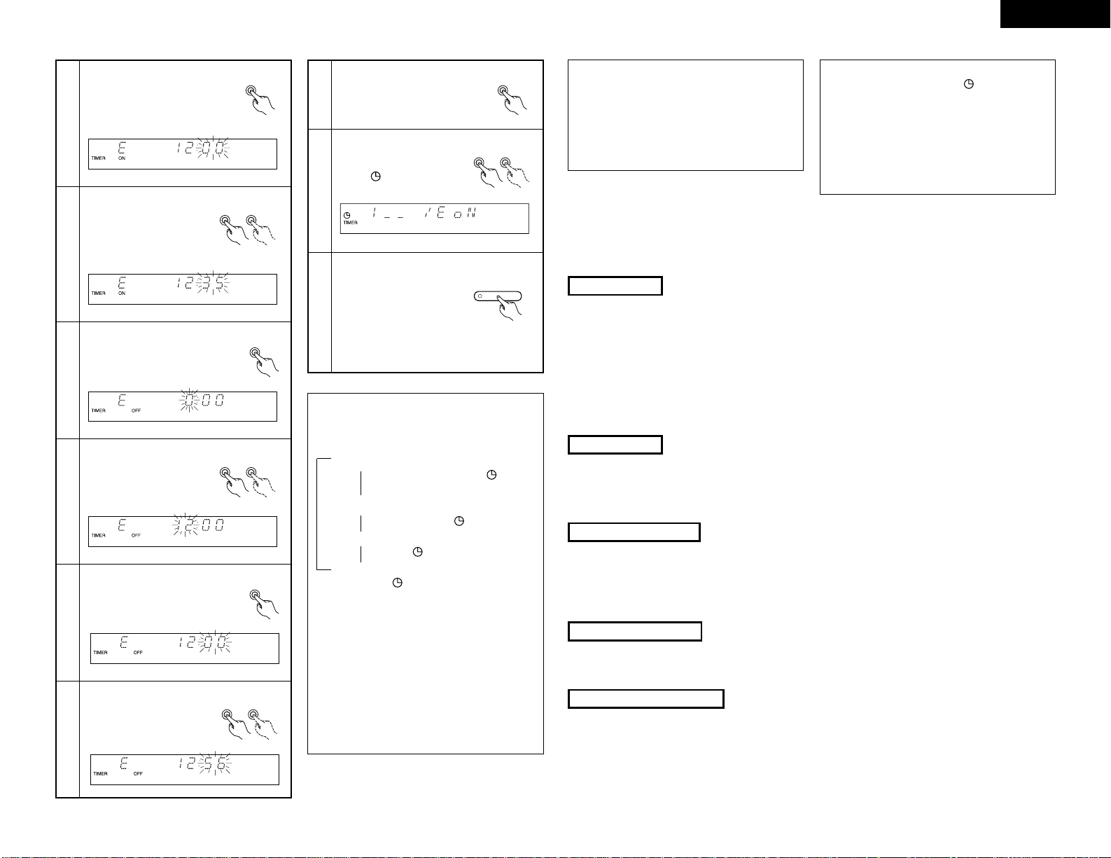
<Setting the
PRESET/TUNING on time>
Use the tuning buttons to set
the hours position to “12”.
9
DOWN UP
PRESET / TUNING
Page 17
17
ENGLISH
1 oN/E oN: Both once and everyday timers
are activated. (The mark
lights.)
1_ _/E oN: Only the everyday timer is
activated. (The mark lights.)
1 oN/E_ _: Only the once timer is activated.
(The mark lights.)
1_ _/E_ _: Both timers are canceled. (The
mark turns off.)
10
Press the MEMORY/SET button.
•“12” is stored in the memory
for the hours position.
MEMORY
/ SET
Use the PRESET/TUNING
buttons to set the minutes
position to “35”.
DOWN UP
PRESET / TUNING
11
16
Press the MEMORY/SET button.
• The off time is stored in the
memory.
MEMORY
/ SET
Use the PRESET/TUNING
Button to select ”E oN”.
• The “” mark lights.
DOWN UP
PRESET / TUNING
17
12
Press the MEMORY/SET button.
• The on time is stored in the
memory and the timer off time
setting mode is set.
MEMORY
/ SET
<Setting the timer off
time>
Use the PRESET/TUNING
buttons to set the hours
position to “12”.
DOWN UP
PRESET / TUNING
13
14
Press the MEMORY/SET button.
•“12” is stored in the memory
for the hours position.
MEMORY
/ SET
Use the PRESET/TUNING
buttons to set the minutes
position to “56”.
15
DOWN UP
PRESET / TUNING
✽
Turning on and off the timer standby ON/OFF
• In TIMER STANDBY mode, each time the
PRESET/TUNING button is pressed, the setting
changes as follows:
18
Turn off the power.
When the DRA-201SA is
connected in a system with
the 201SA series, press the
power button on the receiver.
• The standby mode is set.
(The power switch indicator
turn orange and display turn
off.)
ON / STANDBY
• When you set only the everyday timer, the
indication changes between 1_ _/E_ _ and 1_ _/E
oN.
• When you set only the once timer, the indication
changes between 1_ _/E_ _ and 1 oN/E_ _.
• When you complete the setting, the display
automatically returns to the former state after 5
seconds.
• To change the settings of TIMER STANDBY, press
TIMER button to set the unit in TIMER STANDBY
mode first, the use PRESET/TUNING button to
make changes.
1
1
1
1
1
1
1
1
✽
When the timer start time is reached, the timer
operates.
✽
If “ONCE” is selected in step 3, the once timer
setting mode is selected. Set the timer using the
same procedure. At steps 4 and 8 through 15, “1”
(for once) is displayed instead of “E”.
The once timer is activated when “1 oN” is
displayed at step 17.
NOTES:
• The timer standby indicator (“”) will not light if
the current time is not set. If this happens, set the
current time. (Refer to “Setting the Current Time”
on page 16.)
• When the timer on time is reached while in the
standby mode, operation switches to the operation
set with the timer. (The timer setting has priority.)
• Set the standby mode when using the timer. The
timer may not operate properly if the power is on.
(4) Using the timer
The time and timer functions are incorporated in this unit.
2 Types of timer operations
EVERYDAY TIMER : Use this to turn the power on and standby at the same times every day.
ONCE TIMER : Use this to turn the power on and standby once.
SLEEP TIMER : Use this to set the power to turn standby after 10 to 60 minutes, in steps of 10 minutes (operated
from the remote control unit).
2 Notes on timer settings
• Be sure to set the current time beforehand.
• To listen to or record a radio program (”air check“) using the timer, be sure to preset the station beforehand. (Refer to
”Presetting AM and FM Stations“ on Page 14.)
Timer Settings
Power Failures
Checking the Settings
If the power cord is unplugged or there is a power failure, the settings of the current time and once timer are erased and
the time display will flash. If this happens, reset the current time and the once timer.
Also check the timer and tuner presettings, and reset them if they have been cleared.
To check the timer settings, press the TIMER button for at least 3 seconds to select EVERYDAY or ONCE TIMER.
Next, press the PRESET/TUNING button to select EVERYDAY or ONCE TIMER, then press MEMORY/SET button
repeatedly to display in order: Timer Start mode, and (when in TUNER mode) the reception band and preset channel
number, Timer On time, Timer Off time, Press the MEMORY/SET button again to return to the current mode display.
Changing the Settings
Repeat the timer setting operation to erase the previous settings and set the new settings.
Note on Setting the Timer
If the time set with the timer is reached while the system power is on, the operation switches to the operation set by
the timer.
Page 18
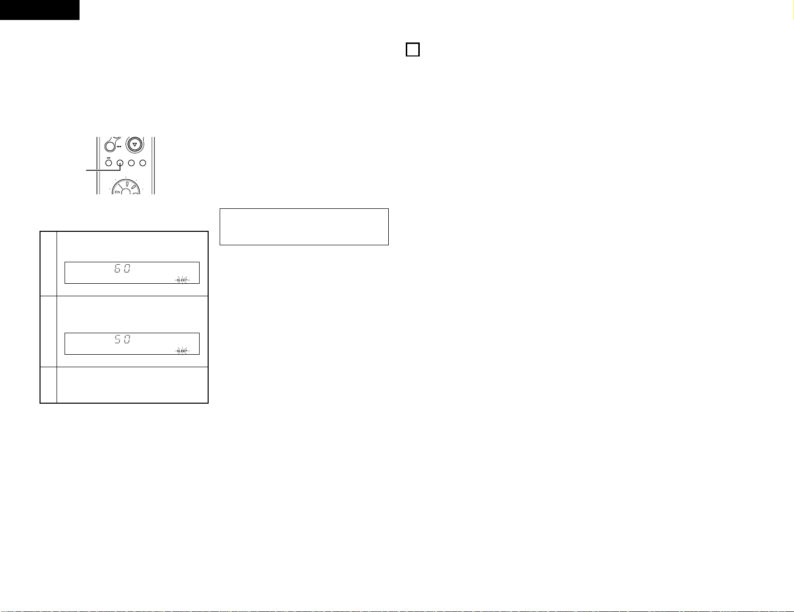
18
ENGLISH
(5) Timer function
(when connected in a system with the 201SA series)
2 The power can be set to turn on and off at a specific time or at the same time everyday, in any modes: tuner
(“TUNER”), CD player (“CD”), cassette deck (“TAPE”), MD recorder (“MD”) and timer recording (recording to the
cassette deck (“AIRCH”) or the MD recorder (“AIRCH MD”) from the tuner).
1
Press the SLEEP button.
2
Press the SLEEP button again while the
”SLEEP” indicator is flashing.
Example: To turn the power off after 50 minutes.
(This operation is only possible from the remote
control unit (RC-906).)
3
The previous display reappears after 5 seconds.
The “SLEEP” indicator remains lit, indicating
that the sleep timer is functioning.
Cancelling the Sleep Timer
Press the SLEEP button repeatedly until the “SLEEP”
indicator turns off.
The sleep timer is also canceled if the power operation
switch or the power operation switch on the remote
control unit is pressed, turning the system power off.
NOTE:
If a several timer operations are set at once, the sleep
timer has priority.
• The time is reset to “60” (60 minutes) if the SLEEP
button is pressed again while the sleep timer is
functioning.
SLEEP MODE
TAPE
FUNCTION
-
TUNER
CD
CD-R
MD
TAPE
1,2
RC-906
(system remote
control unit)
(6) Setting the Sleep Timer
2 With this function, the power can be set to turn off after 10 to 60 minutes, in steps of 10 minutes, using the remote
control unit.
10
SYSTEM FUNCTIONS
2 Operation is even easier when the components in the 201SA series are connected to the DRA-201SA with system
connections. (For instructions on connections, refer to “CONNECTIONS” on page 6, 7.)
2 All the system function signals for operating the components in the 201SA series are output from the DRA-201SA, so
be sure to connect the DRA-201SA when making system connections.
2 The system functions will only work when the components of the 201SA series are connected. They will not work
with other components.
2 When system connections are made, the system functions described below can be used.
(1) The system remote control unit (RC-906) included with the DRA-201SA can be used to perform the main
operations on the other components.
(2) The remote control signals of the other components are received by the DRA-201SA’s remote sensor.
(3) Auto power on function:
When the system is set to the standby mode, the power turns on automatically when the PLAY/PAUSE button
(
1 3
) on the CD player (DCD-201SA), cassette deck (DRR-201SA), and MD recorder (DMD-201SA) is pressed,
and playback begins.
(4) Auto function selection:
The function automatically switches when the PLAY/PAUSE button (
1 3
) on the CD player (DCD-201SA),
cassette deck (DRR-201SA), and MD recorder (DMD-201SA) is pressed, and playback begins.
(5) CD synchronized recording:
CDs can be recorded on the cassette deck (DRR-201SA), MD recorder (DMD-201SA) simply by pressing the CD
SRS button on the cassette deck.
(6) Simultaneous recording:
When the PLAY/PAUSE button (
1 3
) on the CD player (DCD-201SA) is pressed while the cassette deck (DRR-
201SA), MD recorder (DMD-201SA) is set to the recording pause mode, recording starts automatically.
(7) Timer functions:
The timer functions on the stereo receiver (DRA-201SA) can be used to start playback or record radio programs
(“air check”) at set times. The sleep timer can also be used.
2 For instructions on the various operations, refer to the components’ operating instructions.
Page 19
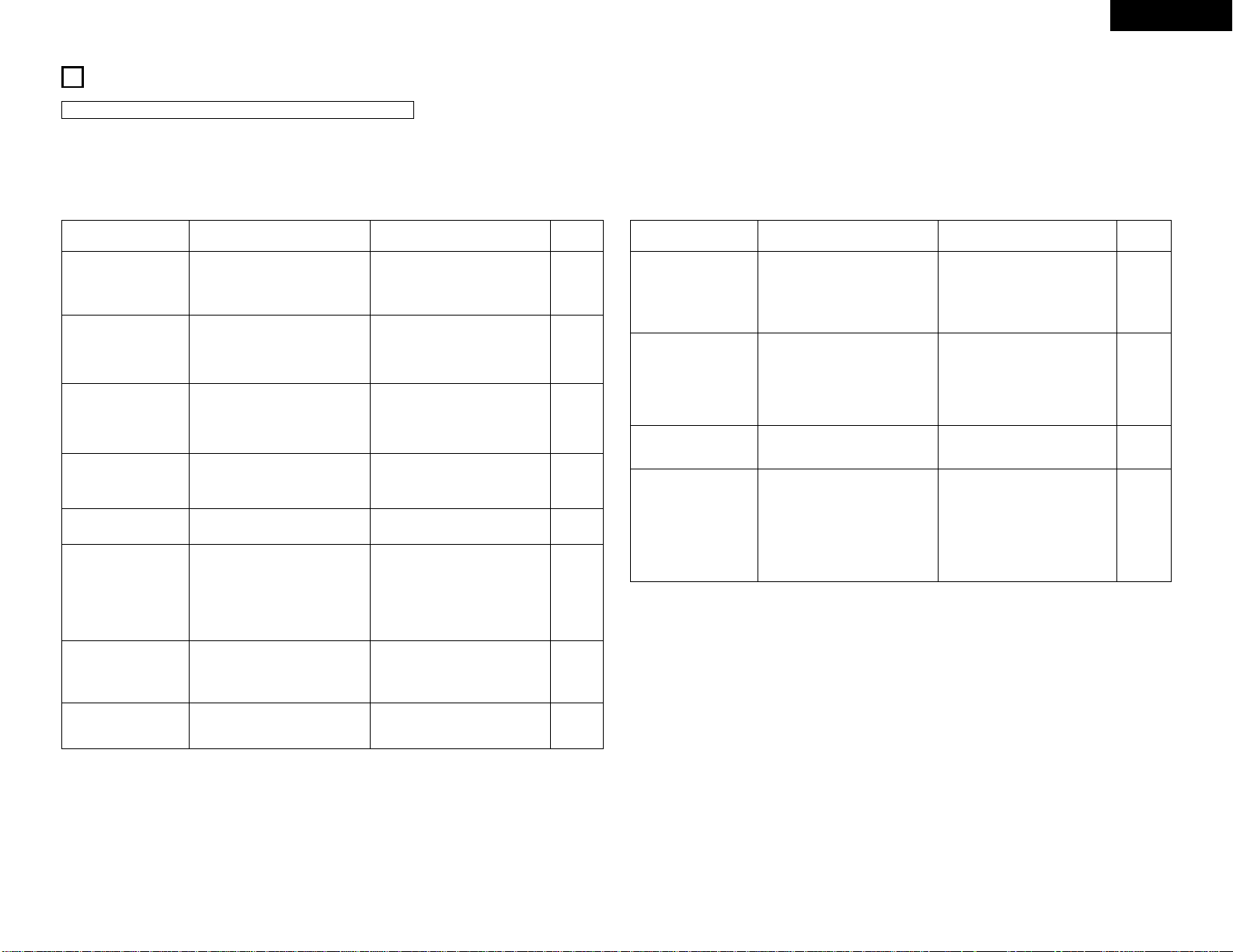
19
ENGLISH
11
TROUBLESHOOTING
1. Are all connections proper ?
2. Is the set being operated as described in the operating instructions ?
3. Are the speakers and input components being operated properly ?
If the set does not seem to be operating properly, check the points listed below. If these points do not apply, the set
may be damaged. Turn off the power immediately and contact your store of purchase.
Symptom Cause Remedy page
POWER LED does not
light and no sound is
produced when POWER
switch is turned on.
• Power supply cord is not connected. • Check that the cord is plugged in. 6, 8
POWER LED lights but no
sound is produced.
• Speaker cords not properly
connected.
• INPUT SELECTOR not set to proper
position.
• VOLUME control turned down.
• Connect securely.
• Set to the proper position.
• Set to an appropriate level.
6, 7
12
12
Sound is not produced
from one side only.
• Speaker cords not properly connected.
• Input cords not properly connected.
• Left/right balance improperly
adjusted.
• Connect securely.
• Connect securely.
• Adjust the BALANCE control.
7
6
13
Volume level is different
when listening to tuner
and records.
• Tuner and record outputs different. • Adjust the tuner output to the
turntable’s output (if the tuner is
equipped with an output control).
—
Positions of instruments
inverted for stereo sources.
• Left and right speakers or input
cords inverted.
• Check the left/right connections. 6, 7
Hissing noise is heard
when an FM station is
tuned in.
• Is the antenna cable properly
connected?
• Is there interference from an
electronic device equipped with a
microprocessor, or is the signal of
the FM station weak?
• Connect the antenna cable properly.
• Change the position of the
equipment or change the position or
direction of the connection cords and
antenna.
• Connect an outdoor antenna.
5
5, 6, 7
5
Scratchy or hissing noise
is heard when an AM
station is tuned in.
• Is there interference from a TV set,
or interference from another
broadcast station?
• Turn off the TV.
• Change the position or direction of
the AM antenna.
• Connect an outdoor antenna.
—
5
5
Humming noise is heard
when an AM station is
tuned in.
• Is the signal carried over the power
cord being modulated by the power
supply frequency?
• Insert the power plug in the opposite
direction.
• Connect an outdoor antenna.
—
5
Check the following before assuming there is a problem with the set.
Symptom Cause Remedy page
Booming sound produced
when playing records.
• Turntable’ s ground wire not
connected.
• Input cords not properly connected
to PHONO terminals.
• Influence from a TV or other
electrical device near the turntable.
• Connect securely.
• Connect securely.
• Change the position of installation.
6
6
—
Howling produced when
volume is turned up while
playing records.
• Turntable and speaker systems are
too close.
• Floor is soft and vibrates easily.
• Move speaker systems as far away
as possible.
• Use cushions to absorb the
vibrations transmitted from the floor
to the speakers. If the turntable does
not include insulators, use audio
insulators, available in stores.
—
—
Sound is distorted.
This unit does not operate
properly when remote
control unit is used.
• Stylus pressure is too light.
• Dirt on tip of stylus.
• Defective cartridge.
• Batteries dead.
• Remote control unit too far from this
unit.
• Obstacle between this unit and
remote control unit.
• Different button is being pressed.
• < and > ends of battery inserted in
reverse.
• Apply proper pressure.
• Check the tip of the stylus.
• Replace the cartridge.
• Replace with new batteries.
• Move closer.
• Remove obstacle.
• Press the proper button.
• Insert batteries properly.
—
—
—
9
10
10
10
9
Page 20

20
ENGLISH
12
SPECIFICATIONS
2 POWER AMPLIFIER SECTION
Rated Output Power: 50 W + 50 W (4 Ω/ohms, DIN, 1 kHz, T.H.D. 0.7%)
Output terminals: 4 to 16Ω/ohms
• PRE AMPLIFIER SECTION
Rated Output: 150 mV (Recout Terminal)
Input Sensitivity/
Input Impedance:
PHONO: 2.5 mV/47 kΩ/kohms
CD, DVD/AUX,
TAPE, MD, AUX-2: 100 mV/16 kΩ/kohms
RIAA Deviation: PHONO: 20 Hz to 20 kHz ±0.5 dB
• OVERALL CHARACTERISTICS
SN Ratio (IHF A Network): PHONO: 80 dB (at 5 mV input) (input terminals short-circuited)
CD, DVD/AUX,
TAPE, MD, AUX-2: 102 dB (SOURCE DIRECT: ON)
Frequency Response: 5 Hz to 80 kHz : +0, –3 dB (SOURCE DIRECT: ON)
Tone Control Adjustable Range: BASS: 100 Hz ±8 dB
TREBLE: 10 kHz ±8 dB
LOUDNESS: 100 Hz +8 dB
10 kHz +6 dB
2 TUNER SECTION
Reception frequency range: FM : 87.50 MHz ~ 108.00 MHz
AM : 522 kHz ~ 1611 kHz
Practical sensitivity: FM : 1.2 µV/75 Ω/ohms (12.8 dBf)
AM : 18 µV
FM stereo isolation: 40 dB (1 kHz)
FM S/N ratio: Monaural: 77 dB Stereo: 71 dB
FM harmonic distortion: Monaural: 0.3% Stereo: 0.4%
Timer functions: Everyday timer (1 setting)
Once timer (1 setting)
Sleep timer (maximam 60 min.)
• OTHERS
Power Supply: AC 230 V, 50 Hz
Power Consumption: 110 W
(Approx. 1W in standby mode)
Dimensions: 250 (W) X 90 (H) X 371 (D) mm
Mass: 6.2 kg
• REMOTE CONTROL UNIT (RC-906)
Remote control system: Infrared pulse system
Power supply: 3 V DC, Two size R03 (“AAA”)
dry cell batteries
External dimensions: 48 (W) X 210 (H) X 29 (D) mm
Mass: 120 g
(including batteries)
• For improvement purposes, specifications and functions are subject to change without advanced notice.
Page 21
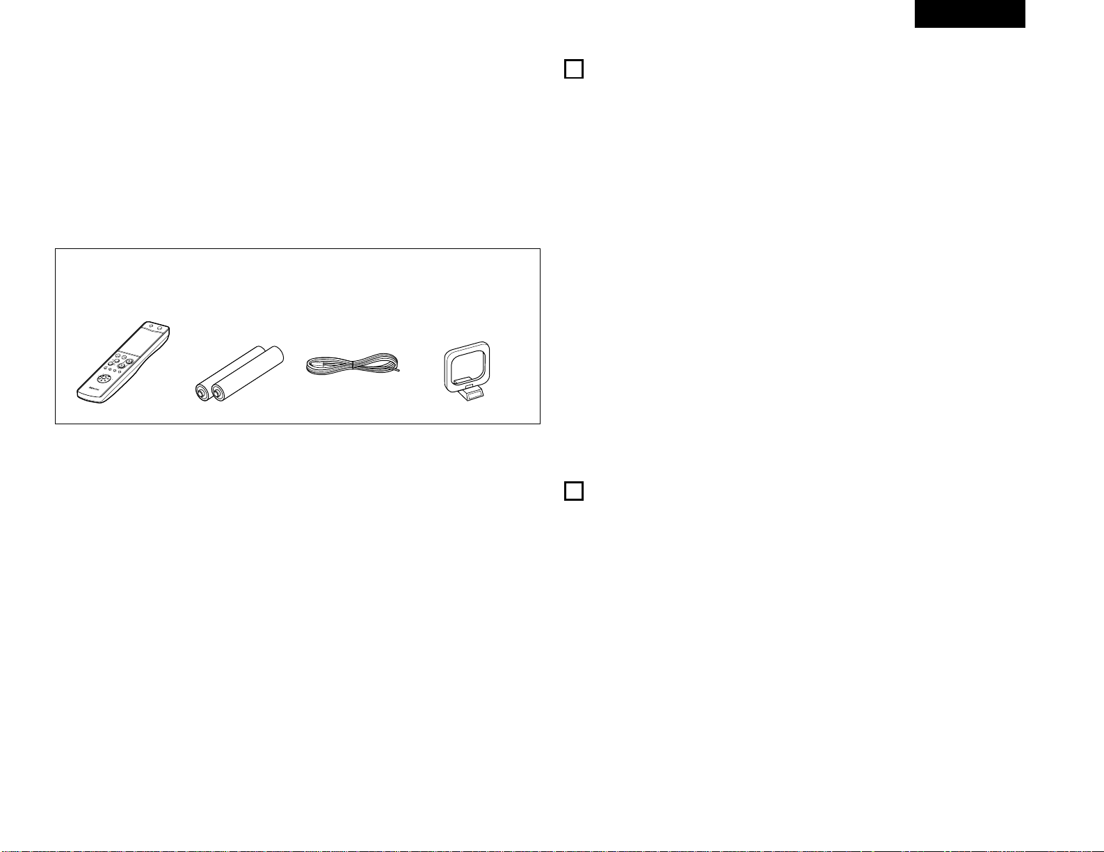
DEUTSCH
21
INHALT
z
HAUPTMERKMALE ………………………………… 21
x
VOR INBETRIEBNAHME …………………………… 21
c
ANSCHLUSS DER ANTENNEN …………………… 22
v
ANSCHLÜSSE …………………………………… 23
, 24
b
BAUTEILBEZEICHNUNGEN
UND FUNKTIONEN ……………………………… 25
, 26
n
SYSTEMFERNBEDIENUNG ……………………
26~28
m
BETRIEB …………………………………………
29, 30
,
RADIO HÖREN …………………………………
30~32
.
VERWENDUNG DES TIMERS ………………
33~35
⁄0
SYSTEMFUNKTIONEN ………………………………
35
⁄1
FEHLERSUCHE ………………………………………
36
⁄2
TECHNISCHE DATEN ………………………………
37
Stellen Sie sicher, daß die nachfolgend aufgeführten Zubehörteile dem Hauptgerät beiliegen:
2
ZUBEHÖRS
q Fernbedienungsgerät (RC-906) ………………………1
w R03 (AAA)-Batterien ……………………………………2
e UKW-Antennenadapter ………………………………1
r MW-Raumantenne ……………………………………1
t Betriebsanleitung ………………………………………1
y Kundendienstverzeichnis ……………………………1
qwer
RC
-906
R
E
M
O
T
E
C
O
N
T
R
O
L
U
N
I
T
C
L
E
A
R
5
5
C
D
S
R
S
M
D
T
A
P
E
C
D
-
R
T
U
N
I
N
G
R
E
V
.
M
O
D
E
D
O
L
B
Y
R
E
P
E
A
T
C
A
L
L
PROG/
DIRECT
R
A
N
D
O
M
B
A
N
D
P
T
Y
R
D
S
D
I
M
M
E
R
T
I
M
E
/
P
A
N
E
L
T
I
M
E
E
D
I
T
S
Y
S
T
E
M
P
O
W
E
R
O
F
F
O
N
S
T
O
P
P
L
A
Y
VO
LUM
E
/
S
E
L
E
C
T
S
L
E
E
P
M
O
D
E
T
A
P
E
F
U
N
C
T
I
O
N
P
R
E
S
E
T
+
-
T
U
N
E
R
C
D
C
D
R
M
D
T
A
P
E
+
-
1
23
64
7
8
9
+
10
0
1. HC-TR-Ausgangsschaltung für Feinheit und
Leistung
Eine einfache Gegentaktschaltung mit einem HC-TR
(Starkstrom-Transistor), der auf den gleichen Prinzipien
basiert wie das UHC-MOS im POA-S1, dem
erstklassigen monauralen Leistungsverstärker von
DENON, erzielt eine stabile Starkstromversorgung und
eine exzellente Kleinsignallinearität. Das Ergebnis ist
ein hoher Grad an Feinheit und Leistung.
2. Die leistungsfähige Starkstromschaltung
unterstützt die ausdrucksstarken Fähigkeiten der
HC-TR-Ausgangsschaltung
Die leistungsfähige Starkstromschaltung besteht aus
Hochleistungs-Gleichrichterdioden und großen
Tonqualitätsblock-Kondensatoren, die dafür sorgen,
dass sich das maximale Potential der HCTransistorausgangsschaltung entfalten kann.
3. S.L.D.C.
Beim DRA-201SA kommt die S.L.D.C. (Signal Level
Divided Construction) für die Trennung der
unterschiedlichen Schaltungen zum Einsatz
(Kleinsignalschaltung, Großsignalschaltung,
Mikroprozessorschaltung, usw.)
4. Quellen-Direktfunktion für bessere Tonqualität
Der DRA-201SA ist mit einer Quellen-Direktfunktion
ausgestattet, die den Tiefen-, Höhen-, Loudness- und
Balance-Schaltkreis umleitet, um einen einzigen
Signalweg zu erhalten, der dafür sorgt, dass der Ton
klar bleibt.
5. Kompatibel mit RDS
Kompatibel mit verschiedene RDS-Services,
einschließlich Programmservicenamen (PS),
Programmsparten-Identifikation (PTY),
Verkehrsprogramm-Identifikation (TP), Uhrzeit (CT) und
Radiotextmeldungen (RT).
6. MW/UKW-Tuner mit Zufallsvoreinstellungsfunktion
für 40 Sender
7. System-Fernbedienungsgerät
Der DRA-201SA ist mit einem SystemFernbedienungsgerät ausgestattet, das für die
Steuerung der verschiedenen Komponenten innerhalb
der 201SA-Reihe (CD-Player, MD-Recorder und
Kassettendeck bei Verwendung mit Systemanschluss)
verwendet werden kann.
8. Niedriger Stromverbrauch im Bereitschaftsbetrieb
Der Stromverbrauch im Bereitschaftsbetrieb wird auf
1 W oder weniger reduziert.
1
HAUPTMERKMALE
2
VOR INBETRIEBNAHME
Beachten Sie vor der Inbetriebnahme des Gerätes die
nachfolgend aufgeführten Hinweise:
• Transport des Gerätes
Um sowohl Kurzschlüsse als auch eine Beschädigung
der Drähte in den Anschlußkabeln zu vermeiden,
müssen vor einem Transport des Gerätes sowohl das
Netzkabel als auch alle Anschlußkabel zwischen den
einzelnen Audio-Komponenten abgetrennt sein.
• Vor dem Einschalten des Netzschalters
Vergewissern Sie sich noch einmal, daß alle
Anschlüsse richtig ausgeführt worden sind und es
keinerlei Probleme mit den Anschlußkabeln gibt.
Stellen Sie den Netzschalter vor dem Anschließen bzw.
Abtrennen von Anschlußkabeln stets auf die StandbyPosition.
• Bewahren Sie diese Betriebsanleitung an einem
sicheren Ort auf.
Bewahren Sie diese Betriebsanleitung nach dem
Durchlesen zusammen mit der Garantiekarte an einem
sicheren Ort auf.
• Beachten Sie bitte, daß die Abbildungen in dieser
Betriebsanleitung für Erklärungszwecke vom
aktuellen Gerätemodell abweichen können.
Page 22
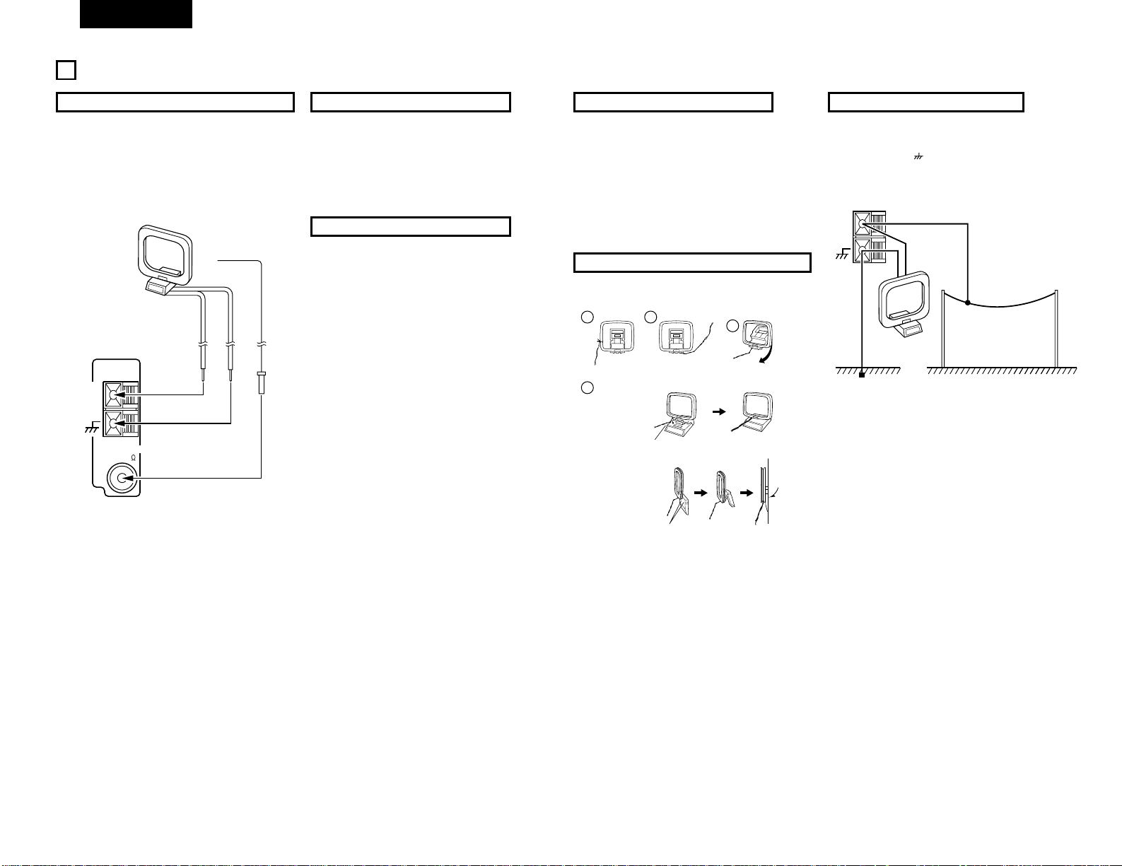
DEUTSCH
22
3
ANSCHLUSS DER ANTENNEN
Montage der UKW-Zimmerantenne
Stellen en Sie einen UKW-Sender ein (Siehe seite 30),
richten Sie die Antenne so aus, daß Tonverzerrungen und
Störgeräusche möglichst gering ausfallen, und fixieren Sie
dann die Spitze der Antenne mit Klebeband oder einer
Haftzwecke in dieser Position.
AM
LOOP
ANT.
FM COAX. 75
ANTENNA
UKW-Antenne
MW-Rahmenantenne
Montage der MW-Außenantenne
Verbinden Sie den Signalleiter der MW-Außenantenne mit
dem Antennenanschluß. Verbinden Sie den Leiter für die
Signalerde mit dem
-Anschluß. Schließen Sie darüber
hinaus auch die mitgelieferte MW-Rahmenantenne an.
AM
LOOP
ANT.
Signalerde
MW-Außenantenne
Zusammenbau der MW-Rahmenantenne
Schließen Sie an den MWAntennenanschlüssen an.
Biegen Sie in
Gegenrichtung.
Entfernen Sie den
Plastikbinder und ziehen
Sie die Verbindungsleitung
auseinander.
Mittels den Installationsbohrungen an
der Wand, etc. befestigen
Stellen
a. Mit der
Antennenach
oben auf eine
ebene Fläche
b. Montage der
Antenne an
der Wand.
MW-Rahmenantenne
Montage der MW-Rahmenantenne
Stellen Sie einen MW-Sender ein (Siehe seite 30), und
richten Sie die Antenne in möglichst großer Entfernung
vom Gerät so aus, daß Tonverzerrungen und
Störgeräusche möglichst geringt ausfallen. In manchen
Fä llen empfiehlt es sich, die Polung der Antenne
umzukehren. MW-Sender lassen sich nicht in
zufriedenstellender Qualität empfangen, wenn keine
Rahmenantenne angeschlossen ist oder wenn diese sich
zu nahe an metallenen Gegenständen befindet.
Montage der UKW-Außenantenne
• Richten Sie die Antenne auf die Sendeantenne des
Senders aus. Wenn sich hohe Gebäude oder Berge
zwischen der Empfangs- und der Sendeantenne
befinden, variieren Sie Standort bzw. Ausrichtung der
Antenne, bis Sie die bestmögliche Einstellung gefunden
haben.
• Antenne nicht unter Hochspannungsleitungen errichten.
Bei Berührung der Hochspannungsleitungen mit der
Antenne besteht Lebensgefahr.
• Antenne möglichst weit entfernt von Strßen bzw.
Eisenbahnlinien montieren, um Störeinflü sse zu
vermeiden.
• Antenne nicht zu hoch installieren, um Blitzeinschlag zu
vermeiden.
Anschluß an UKW-Außenantenne
Wenn sich mit der mitgelieferten UKW-Antenne kein
einwandfreier Empfang erzielen läßt, muß das Gerät an
eine UKW-Außenantenne angeschlossen werden.
Verbinden Sie einen Winkelstecker des IEC-Typs mit dem
Koaxialkabel, und schließen Sie die Antenne an dem
Eingang FM COAX (75Ω/Ohm) an.
1
4
2
3
Page 23
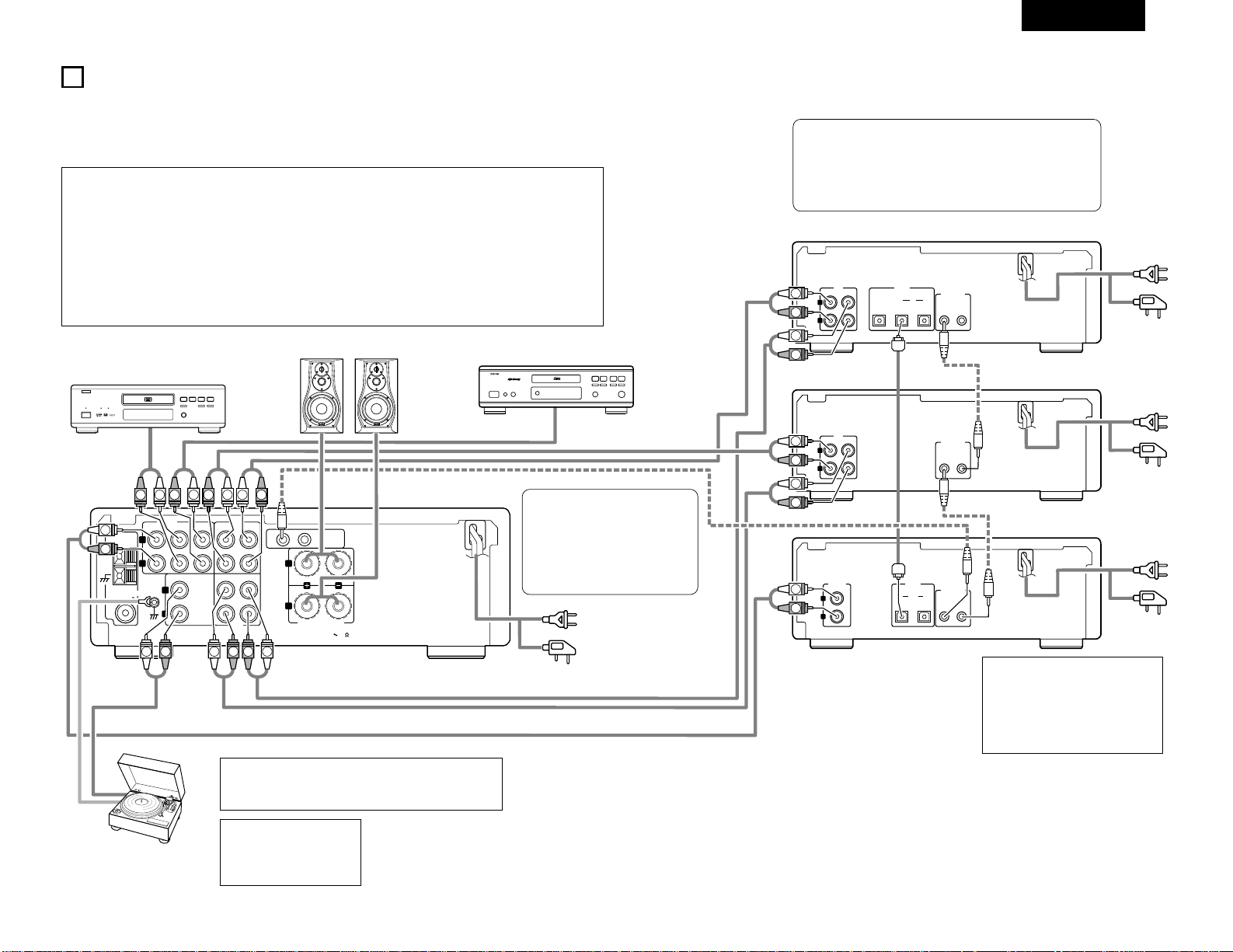
DEUTSCH
23
LINE
L
R
OUT IN
OUT 1
12
IN 2
OPTICAL
DIGITAL
CONNECTOR
SYSTEM
LINE
L
R
OUT IN
12
CONNECTOR
SYSTEM
12
CONNECTOR
SYSTEM
LINE OUT
L
R
1 OUT 2
OPTICAL
DIGITAL
SIGNAL
GND
12
SYSTEM
CONNECTOR
L
R
SPEAKER SYSTEM
SPEAKER IMPEDANCE
4 16
CD
DVD/AUX
PHONO TAPE MD
AUX-2 TAPE MD
PB
REC
INPUTS
L
R
L
R
AM
LOOP
ANT.
FM COAX. 75
ANTENNA
R
L
RLL
R
L
R
LRLRL
RRL
R
L
R
L
R
L
R
L
DVD
B
R
L
DIGITAL AUDIODIGITAL AUDIO
(L)
(R)
4
ANSCHLÜSSE
2 Beziehen Sie sich beim Ausführen der Anschlüsse ebenfalls auf die Bedienungsanleitungen der anderen Komponenten.
2 Wenn ein Anschluss an die 201SA-Serie erfolgt, nehmen Sie die im Diagramm unten durch gepunktete Linien
gekennzeichneten Systemanschlüsse vor.
2 Der DRA-201SA wird nicht mit Anschlusskabeln geliefert. Die den Komponenten beiliegenden Anschlusskabel für den
Anschluss des DRA-201SA verwenden.
HINWEIS:
•
Schließen Sie die Erdungsleitung
an. Trennen Sie sie jedoch
wieder ab, wenn Brummen oder
andere Geräusche auftreten.
• Schließen Sie beim Ausführen von Systemanschlüssen an die
201SA-Serie das Systemkabel an den Systemanschluss des DRA201SA (1 oder 2) an. Schalten Sie andere Systemkomponenten auf
die gleiche Weise zusammen.
(Systemanschlüsse sind im Diagramm durch gepunktete Linien
gekennzeichnet.)
Lautsprechersystem
CD-Spieler
MD-Rekorders
(DMD-201SA)
Cassettendeck
(DRR-201SA)
CD-Spieler
(DCD-201SA)
HINWEISE:
• Stecken Sie das Netzkabel erst dann ein, nachdem alle Verbindungen beendet sind.
• Stellen Sie sicher, daß der linke und rechte Kanal richtig verbunden wurde (links mit links, rechts mit rechts).
• Achten Sie auf sichere Steckverbindungen. Schlechte Kontakte verursachen Störungen.
• Beachten Sie bitte, daß durch das Zusammenbinden von Steckverbindungen mit dem Netzkabel oder wenn diese in der
Nähe des Netztransformators geführt werden, Brummen oder andere Störungen erzeugt werden können.
• Die PHONO-Anschlußklemmen haben eine außergewöhnlich hohe Empfindlichkeit. Vermeiden Sie daher das Erhöhen der
Lautstärke, wenn keine Stiftsteckerkabel angeschlossen sind. Andernfalls kann es zu einem Induktionsbrummen (dröhnen)
von den Lautsprechern kommen.
• Der Ton einer anderen Komponente kann gehört werden, wenn keine Komponente an die Eingangsbuchsen der mit dem
FUNCTION-Wähler eingestellten Funktion angeschlossen ist.
DVD-Spieler
Netzkabel
(für die U.K.-Modell)
Netzstecker
Wechselstrom 230 V,
50 Hz
(In die Netzsteckdose
stecken)
Netzkabel
(für die U.K.-Modell)
Netzstecker
Wechselstrom 230 V,
50 Hz
(In die Netzsteckdose
stecken)
Netzkabel
(für die U.K.-Modell)
Netzstecker
Wechselstrom 230 V,
50 Hz
(In die Netzsteckdose
stecken)
Netzkabel
(für die U.K.-Modell)
Netzstecker
Wechselstrom 230 V, 50 Hz
(In die Netzsteckdose stecken)
Plattenspieler
(MM-Tonabnehmer)
HINWEIS:
Dieses Gerät kann nicht direkt mit MM-Tonabnehmern benutzt
werden. Verwenden Sie einen Hauptverstärker oder
Aufwärtstransformator mit MC-Tonabnehmern.
HINWEIS:
• Stellen Sie keine weitere
Komponente oder einen anderen
Gegenstand direkt auf den DRA201SA, damit Hitze entweichen
kann.
• Der Stereo-Receiver der 201SAReihe (DRA-201SA) ist mit einer Uhrund Timerfunktion ausgestattet;
stellen Sie aus diesem Grund sicher,
dass er an eine Wandsteckdose
angeschlossen wird, die fortwährend
mit Strom versort ist.
Page 24
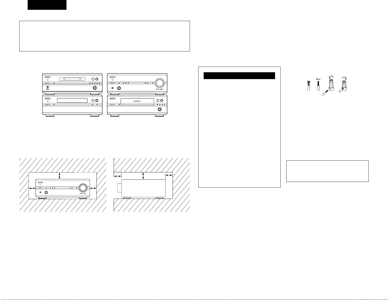
DEUTSCH
24
Systemfunktionen
• Systemfunktionen wie die Timer-Aufnahme/Wiedergabe und autom. Funktionseinschaltung können nur aktiviert
werden, wenn Stereoaudiokabel und Systemkabel zwischen allen Systemkomponenten angeschlossen werden.
Vergewissern Sie sich, dass alle Anschlusskabel zwischen den Einheiten fest angeschlossen sind.
• Wenn ein Systemkabel während des Betriebs abgezogen wird, kann eine Fehlfunktion auftreten. Ziehen Sie
unbedingt die Netzkabel ab, bevor Anschlussänderungen vorgenommen werden.
2
Empfohlene Systeminstallation
• Installieren Sie das System (201SA-Serie) wie unten beschrieben, um Leistung und Stabilität zu gewährleisten.
1 3 2
5
ON / STANDBY
C
8/67/9
TRACK
INDEX
TIME
M
S
COMPACT DISC PLAYER DCD-201SA
ON / STANDBY
1 3 2
5
CD SRSINPUT
MEMO REC /
CHARACTER
EDIT MULTI REC
REC LEVEL / ENTER
8
9
+
MINIDISC RECORDER DMD-201SA
POWER LOADING MECHANISM
ON / STANDBY
12
5
-60 -40 -30 -20 -12 -6 -2 0
L
dB
R
3
DOLBY NR B
DOLBYNRREVERSE
/ RESET
CD SRS
REC LEVEL /
0 1
8
6
9
7
+
STEREO CASSETTE TAPE DECK DRR-201SA
4 REC
/ REC MUTE
CH
MHz
TUNED STEREO AUTO
TIMER
BAND
/ RDS
MEMORY
/ SET
DOWN UP
PRESET / TUNING
PHONES FUNCTION
VOLUME
SOURCE DIRECT
MODEON / STANDBY
STEREO RECEIVERER DRA-201SA
✽
Stellen Sie keine andere Komponente direkt auf den DRA-201SA. Lassen Sie mindestens 10 cm über dem DRA201SA Platz, damit die Ventilationsöffnungen nicht blockiert werden und Hitze entweichen kann.
✽
Stapeln Sie aus Stabilitätsgründen nicht mehr als drei Komponenten übereinander.
(DRR-201SA)
(DMD-201SA)
(DCD-201SA)
Lautsprechersystem-Anschlüsse
2
Lautsprecherimpedanz
Verwenden Sie Lautsprechersysteme mit einer
Impedanz von 4 bis 16Ω/Ohm.
• Beachten Sie, dass die Verwendung von
Lautsprechern mit einer anderen Impedanz die
Schutzschaltung aktiviert und dadurch Schäden
verursacht werden können.
qw e r
(DRA-201SA)
Dieses Gerät ist mit einer
Hochgeschwindigkeits-Schutzschaltung
versehen.
Diese Schaltung dient zum Schutz der
inneren Schaltungen, die sonst leicht
beschädigt werden können, wenn die
Lautsprecherklemmen nicht vollständig
angeschlossen sind, oder wenn ein
Ausgang durch einen Kurzschluß
generiert wird. Bei Einsatz dieser
Schutzschaltung wird der Ausgang zu
den Lautsprecher abgeschnitten. Sehen
Sie in diesem Falle zu, daß der
Netzanschluß des Gerätes abgeschaltet
wird, und daß die Anschlüsse zu den
Lautsprechern überprüft werden.
Schalten Sie den Netzanschluß dann
wieder ein. Nach der mehrere Sekunden
lang dauernden Stummschaltung
funktioniert das Gerät wieder normal.
Schutzschaltung
2
Anschließen der Lautsprecherkabel
q Streifen Sie die Mantelung vom Ende des Kabels ab.
w Drehen Sie die Kabeladern.
e Drehen Sie die Lautsprecherklemme entgegen des
Uhrzeigersinns, um sie zu lösen.
r Setzen Sie die Kabeladern vollständig ein und
drehen Sie die Klemme dann im Uhrzeigersinn, um
sie wieder zu befestigen.
B Achten Sie darauf, daß Sie die Kabel zwischen den
Lautsprecherklemmen und den Lautsprechersystemen
mit den gleichen Polaritäten (< an < , > an > )
anschließen. Andernfalls ist der Mittelklang schwach
und die Position der verschiedenen Instrumente ist
undeutlich. Dies verringert den Stereo-Effekt.
B Achten Sie beim Anschließen der Lautsprecher darauf,
daß die Kabeladern nicht aus den Klemmen
herausragen und andere Klemmen, sich gegenseitig
oder die Rückseite des Gerätes berühren.
HINWEIS:
• Berü hren Sie die Lautsprecherklemmen NIEMALS,
wenn der Strom eingeschaltet ist. Dies könnte einen
elektrischen Schlag verursachen.
Zur Gewährleistung einer ausreichenden Wärmeabfuhr, sollte oberhalb, seitlich sowie hinter dem Gerät ein
Mindestabstand von 10 cm zur Wand oder zu anderen Komponenten eingehalten werden.
CH
MHz
TUNED STEREO AUTO
TIMER
BAND
/ RDS
MEMORY
/ SET
DOWN UP
PRESET / TUNING
PHONES FUNCTION
VOLUME
SOURCE DIRECT
MODEON / STANDBY
STEREO RECEIVERER DRA-201SA
• Umschalten der Eingangsfunktion, wenn keine
Eingangsbuchsen angeschlossen sind
Wenn die Eingangsfunktion umgeschaltet wird, wenn
nichts an die Eingangsbuchsen angeschlossen wurde,
ist möglicherweise ein Klicken zu hören. Drehen Sie in
einem derartigen Fall entweder den MASTER
VOLUME-Regler herunter oder schließen Sie
Komponenten an die Eingangsbuchsen an.
Trennen Sie unbedingt das Netzkabel ab, wenn Sie
für einen längeren Zeitraum, z.B. im Urlaub, nicht
zuhause sind.
5 cm
10 cm oder mehr
✽
✽
✽
✽
✽
Page 25
!3
UKW-Antennenanschluss
(ANTENNA TERMINAL FM)
• Schließen Sie die UKW-Antenne hier an.
!4
SIGNAL GND (Erdungsklemme)
• Schließ en Sie die Erdungsleitung des
Plattenspielers hier an.
!5
INPUT-Anschlüsse (INPUTS)
Dies sind Eingangsanschlüsse fü r CD-Player,
Plattenspieler, DVD oder andere
Wiedergabekomponenten.
• AUX-2:
Schließen Sie hier ein Video Deck oder eine
andere Komponente an.
!6
TAPE- und MD REC-Anschlüsse (REC)
• Aufnahmeanschlüsse (REC)
• Dies sind Ausgangsanschlüsse für die Aufnahme.
• TAPE:
Schließen Sie hier ein Cassetten Deck an.
• MD:
Schließen Sie hier ein MD-Recorder an.
!7
Netzkabel
• Schließ en Sie das Kabel an eine
Wandnetzsteckdose an.
!8
Lautsprechersystem-Klemmen
(SPEAKER SYSTEM)
• Schließen Sie die Lautsprechersysteme hier an.
!9
Systemanschlüsse
(SYSTEM CONNECTOR 1 und 2)
• Schließen Sie beim Zusammenschluss der 201SASerie zu einem System diese Anschlüsse an die
Systemanschlüsse der anderen
Systemkomponenten an.
(Verwenden Sie die Systemkabel, die den anderen
Komponenten beiliegen.)
@0
TAPE- und MD PLAY-Anschlüsse (PB)
• Wiedergabeanschlüsse (PB)
@1
MW-Antennenanschluss
(ANTENNA TERMINAL AM)
• Schließen Sie die MW-Antenne hier an.
DEUTSCH
25
5
BAUTEILBEZEICHNUNGEN UND FUNKTIONEN
(1) Frontplatte
q
Netzschalter
(ON/STANDBY)
• Mit diesem Schalter wird das komplette System
einbzw, ausgeschaltet.)
• Drü cken Sie diesen Schalter einmal, um das
System einzuschalten, und nochmals, um es in
den Bereitschaftsmodus (STANDBY) zu schalten.
• Die Farbe der LED wechselt je nach
Betriebszustand:
Gerät eingescnaltet: grün
Im Bereitschaftsmodus (STANDBY): rot
Im Timer-Bereitschaftsmodus (TIMER
STANDBY): orange
✻Der Stummschaltungsbetrieb wird aktiviert, wenn
die Netztaste des Hauptgerätes gedrückt und
wenn der Standby-Betrieb mithilfe der
Fernbedienung beendet wird. Die LED blinkt im
Stummschalt-Modus, beendet dann das Blinken
und bleibt erleuchtet, wenn das Gerät
betriebsbereit ist.
✻Wenn die Anzeige orange blinkt (schnell):
Die Schutzschaltung wird aktiviert.
Wenn die geschieht, müssen Sie das Netzkabel
abtrennen, damit die Anzeige ausgeschaltet wird;
anschließend sind die Eingangs- und
Ausgangsanschlüsse auf der Rü ckseite zu
überprüfen. Überprüfen Sie insbesondere, ob ein
Kurzschluss an den Lautsprecherkabeln
aufgetreten ist. Wenn alle Anschlüsse auf ihre
Ordnungsmäßigkeit hin überprüft worden sind,
können Sie das Netzkabel wieder anschließen.
(Warten Sie nach Ausschalten der
Stromversorgung mindestens 10 Sekunden, bevor
Sie sie wieder einschalten.)
• Wenn das DRA-201SA an ein System der 201SASerie angeschlossen wird, dient die Netztaste als
Hauptschalter für das gesamte System. Wenn die
Stromversorgung des DRA-201SA eingeschaltet
wird, wird die Stromversorgung aller
angeschlossenen Systemkomponenten
eingeschaltet.
✻Der DRA-201SA wird mit Strom versorgt, auch
wenn der Bereitschaftsbetrieb aktiviert ist
(geringer Stromverbrauch).
w
PHONES (Kopfhörerbuchse)
• Hier kö nnen Sie ein Paar Kopfhörer (optional
erhältlich) anschließen.
• Wenn der Kopfhö rerstecker in die Buchse
gesteckt wird, wird die Ausgabe über Lautsprecher
automatisch deaktiviert, sodass kein Ton von den
Lautsprechern produziert wird.
e
REMOTE SENSOR (Fernbedienungssensor)
• Dieser Sensor fä ngt die von der drahtlosen
Fernbedienung übermittelten infraroten
Lichtstrahlen auf.
Soll eine Fernbedienung durchgeführt werden, ist
die drahtlose Fernbedienung direkt auf das
Sensorfenster zu richten.
r
Funktionswähler (FUNCTION)
• Wechselt die Eingangsfunktion. Damit werden auch
die Betriebe eingestellt, die mit der Betriebstaste
gewählt wurden.
(Siehe seiten 29, 30.)
t
Betriebstaste (MODE)
• Stellen Sie mit dieser Taste den Tiefen-, Höhenund Balancepegel ein.
(Beziehen Sie sich auf seite 29, 30.)
• Schalten Sie mit dieser Taste die LoudnessFunktion ein und aus.
(Beziehen Sie sich auf seite 30.)
• Stellen Sie mit dieser Taste das
Lautsprechersystem ein.
(Beziehen Sie sich auf seite 30.)
y
Timer-Taste (TIMER)
• Drücken Sie bei eingeschalteter Stromversorgung
diese Taste, um die Anzeige zu bestätigen oder zu
ändern. Bei jeder Tastenbetätigung wechselt die
Anzeige wie folgt.
Uhrzeit: Zeigt die aktuelle Uhrzeit an.
Timer-Bereitschaft: Zeigt den TimerBereitschaftsbetrieb an. Schalten Sie den TimerBereitschaftsbetrieb mit den PRESET/TUNINGTasten ein und aus (Siehe seite 34).
• Drü cken Sie diese Tasten für mindestens 3
Sekunden (Siehe seite 33), um den Timer
einzustellen oder den Timer-Inhalt zu bestätigen
(Siehe seite 34).
Bei jeder Betätigung der PRESET/TUNING-Taste
wechselt das Display wie folgt:
Frequency Clock Timer Standby
TIME EVERYDAY ONCE
TIME: Stellen Sie hiermit die Uhrzeit ein.
EVERYDAY: Stellen Sie hiermit den täglichen
Timer ein.
ONCE: Stellen Sie hiermit den Timer für eine
einmalige Verwendung ein.
• Drücken Sie im BEREITSCHAFTSBETRIEB diese
Taste, um die Uhrzeitanzeige EIN/AUSZUSCHALTEN “Energiesparbetrieb”).
RDS PTY TP
FM AUTO FM MONO AM
• Drücken Sie bei eingestelltem UKW-Band diese
Taste für mindestens 3 Sekunden, um die RDSSuchbetriebe auszuwählen
Bei jeder Tastenbetätigung wechselt die Anzeige
wie folgt.
i
Speicher-/Einstelltaste (MEMORY/SET)
• Verwenden Sie diese Taste als Speichertaste,
wenn MW- und UKW-Sender voreingestellt
werden.
• Verwenden Sie diese Taste als Einstelltaste, wenn
die Uhrzeit und der Timer eingestellt und Daten
eingegeben werden.
• Drü cken Sie bei aktiviertem PTY-Suchbetrieb
diese Taste, um die Programmsparte
auszuwählen.
• Drü cken Sie diese Taste für mindestens 3
Sekunden, um die Funktion der RESET/TUNINGTasten zu wechseln (Voreinstellbetrieb oder
Abstimmbetrieb).
o
Display
Beziehen Sie sich auf seite 26.
!0
Voreinstell-/Abstimmtasten
(PRESET/TUNING UP und DOWN)
• Rufen Sie mit diesen Tasten voreingestellte
Sender auf. (PRESET UP DOWN) (Siehe seite 31.)
Stimmen Sie mit diesen Tasten MW- und UKWSender ab. (TUNING UP/DOWN)
(Siehe seite 30.)
!1
Source direct button (SOURCE DIRECT)
• Die Regler (BASS, TREBLE, LOUDNESS und
BALANCE) können betätigt werden, wenn sich
dieser Schalter in der Position OFF befindet.
• Befindet sich der Schalter auf der Position ON,
werden die oben aufgeführten Regler umgangen
und die Signale werden direkt zur
Lautstärkeregler-Steuerung eingegeben. Dies
garantiert einen hochqualitativen Klang.
!2
VOLUME (Lautstärkeregler)
• Dieser Regler dient zur Einstellung der
Gesamtlautstärke (Drehgeber-System).
• Rechtsdrehung (, ) bewirkt eine Erhöhung,
Linksdrehung (. ) eine Verringerung der
Lautstärke.
• Die Erhöhung bzw. Verringerung der Lautstärke
erfolgt in 70 Stufen zwischen dem Mindestwert
(VOLUME 0) und dem Höchstwert (VOLUME
MAX).
(2) Rückwand
HINWEIS:
• Diese Anschlußklemme dient zur Reduzierung
von Störungen, wenn ein Plattenspieler o.ä.
angeschlossen worden ist; sorgt jedoch nicht
für eine komplette Erdung.
u
Band/RDS-Taste (BAND/RDS)
• Wechseln der Frequenzbereichs- und der UKWEmpfangsmodus folgendermaßen:
Page 26
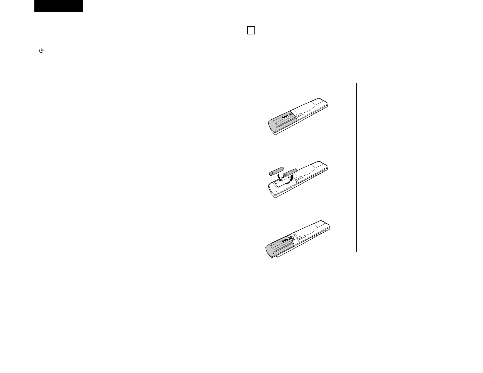
DEUTSCH
26
(3) Display [o]
@3 Voreinstellnummer-Display
• Hier wird die voreingestellte Nummer angezeigt.
@4
Hauptanzeigebereich
• Hier wird die Funktion, die
Eingangsprogrammquelle, usw. angezeigt.
• W ährend des normalen Betriebs wird die
Eingangsprogrammquelle angezeigt.
• Wenn die Betriebstaste gedrückt wird, zeigt die
Anzeige die verschiedenen Funktionen an.
• Das Empfangsband, die Empfangsfrequenz, die
Uhrzeit, die Timer-Einstellzeiten, usw. werden hier
angezeigt.
@2
Betriebsanzeigen
• Diese zeigen die verschiedenen Betriebsarten an.
• :
Leuchtet bei aktiviertem Timer.
• TIME:
Leuchtet auf, wenn das Display auf
Uhrzeitmodus geschaltet ist.
• TIMER:
Leuchtet beim Einstellen des Timers sowie bei
eingestellter Timer-Funktion.
• ON:
Leuchtet, wenn die Timer-Einschaltzeit
eingestellt ist.
• OFF:
Leuchtet, wenn die Timer-Ausschaltzeit
eingestellt ist.
• TUNED:
Leuchtet bei einwandfreiem Empfang eines
Senders.
• STEREO:
Leuchtet auf, wenn eine Stereosendung in UKW
AUTO-Modus empfangen wird.
• MONO:
Leuchtet im AUTO-Modus, wenn ein MonoSender abgestimmt und der MONO-Modus mit
der BAND-Taste eingestellt worden ist
• AUTO:
Leuchtet, wenn der AUTO-Modus mit der
BAND-Taste eingestellt worden ist.
• MEMO:
Blinkt ca. 10 Sekunden, wenn bei der
Senderprogrammierung die MEMORY-Taste
gedrückt wird.
• SLEEP:
Leuchtet bei aktiviertem Ausschalt-Timer.
• RDS (Radio Data System):
Bei Betätigung dieser Taste nimmt das Gerät
die automatische Suche und Abstimmung des
nächsten Senders vor. Zugleich leuchtet die
Meldung “RDS” auf, und der Name des
Senders erscheint im Display.
• PS (Sendermame):
Diese Meldung leuchtet auf, wenn die
Bezeichnung des Senders angezeigt wird.
• TP (Verkehrsfunksender):
Die Meldung “TP” leuchtet auf, wenn ein RDSVerkehrsfunksender empfangen wird.
• PTY (Programmtyp):
Diese Meldung leuchtet auf, wenn ein
bestimmter RDS-Programmtyp eingegeben
wurde.
• RT (Rundfunktext):
Diese Meldung leuchtet auf, wenn sich das
Gerät im RT-Modus befindet und eine RTMeldung eingeht.
2 Mit der beiliegenden Systemfernbedienung (RC-906) können Hauptbedienschritte der durch Systemanschlüsse
verbundenen Einheiten der 201SA-Serie ausgeführt werden.Andere Komponenten können nicht mit dieser
Fernbedienung bedient werden.
Beachten Sie, dass einige Funktionen nicht mit der Systemfernbedienung ausgeführt werden können. Verwenden Sie
in solch einem Fall die Fernbedienung, die zu dieser Komponente gehört.
6
SYSTEMFERNBEDIENUNG
(1) Einlegen der Batterien
q Entfernen Sie die rückwärtige Abdeckung des
Fernbedienungsgerätes.
w Legen Sie die beiden R03 (AAA)-Batterien in der
angegebenen Richtung in das Batteriefach ein.
e Setzen Sie die rückwärtige Abdeckung wieder auf.
Hinweise zu Batterien
• Verwenden Sie im Fernbedienungsgerät R03 (AAA)Batterien.
• Die Batterien sollten ca. einmal jährlich gegen neue
ausgetauscht werden. Wie oft ein Batteriewechsel
jedoch tatsächlich erforderlich ist, hängt von der
Hä ufigkeit der Benutzung des
Fernbedienungsgerätes ab.
• Tauschen Sie die Batterien auch vor Ablauf eines
Jahres aus, wenn sich das Gerät selbst aus nächster
Entfernung nicht mit dem Fernbedienungsgerät
bedienen läßt. (Die mitgelieferte Batterie ist
ausschließlich fü r Testzwecke vorgesehen.
Tauschen Sie die Batterie so bald wie möglich aus.)
• Achten Sie beim Einlegen der Batterien unbedingt
auf die richtige Ausrichtung der Polaritäten. Folgen
Sie den “<”- und “>”-Zeichen im Batteriefach.
• Um Beschä digungen oder ein Auslaufen von
Batterieflüssigkeit zu vermeiden:
• Verwenden Sie keine neuen und alten Batterien
zusammen.
• Verwenden Sie keine verschiedenen
Batterietypen gleichzeitig.
• Schließen Sie Batterien nicht kurz, zerlegen und
erhitzen Sie sie nicht und werfen Sie Batterien
niemals in offenes Feuer.
• Nehmen Sie die Batterien aus dem
Fernbedienungsgerät heraus, wenn Sie
beabsichtigen, es über einen längeren Zeitraum
hinweg nicht zu benutzen.
• Sollte einmal Batterieflüssigkeit ausgelaufen sein,
so wischen Sie das Batteriefach sorgfältig aus und
legen Sie neue Batterien ein.
Page 27
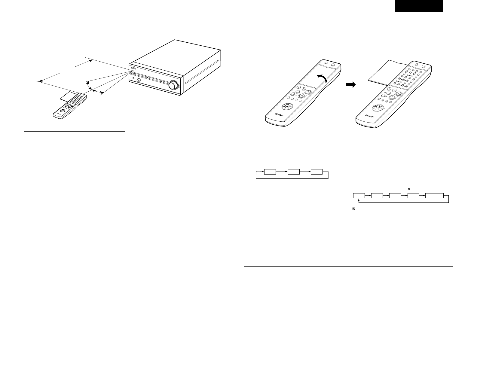
DEUTSCH
27
(2) Fernbedienungsbetrieb
• Richten Sie das Fernbedienungsgerä t - wie im
Diagramm gezeigt - auf den Fernbedienungssensor am
Hauptgerät.
• Die Reichweite des Fernbedienungsgerätes beträgt aus
gerader Entfernung vom Hauptgerät ca. 7 Meter. Diese
Entfernung verkürzt sich jedoch, wenn Gegenstände im
Weg liegen oder das Fernbedienungsgerät nicht direkt
auf den Fernbedienungssensor gerichtet wird.
• Das Fernbedienungsgerät kann in einem horizontalen
Winkel von bis zu 30 Grad zum Fernbedienungssensor
betrieben werden.
RC
-906
R
E
M
O
T
E
C
O
N
T
R
O
L
U
N
I
T
C
L
E
A
R
5
5
+1
0
C
D
S
R
S
M
D
T
A
P
E
C
D
R
T
U
N
I
N
G
R
E
V
.
M
O
D
E
D
o
l
b
y
N
R
R
E
P
E
A
T
C
A
L
L
P
R
O
G
/
D
I
R
E
C
T
R
A
N
D
O
M
B
A
N
D
R
D
S
D
I
M
M
E
R
T
I
M
E
/
P
A
N
E
L
T
I
M
E
E
D
I
T
S
Y
S
T
E
M
P
O
W
E
R
O
F
F
O
N
S
T
O
P
P
L
A
Y
V
O
LU
ME
/
S
E
L
E
C
T
S
L
E
E
P
M
O
D
E
T
A
P
E
F
U
N
C
T
I
O
N
P
R
E
S
E
T
+
-
T
U
N
E
R
C
D
C
D
R
M
D
T
A
P
E
1
2
3
4
6
7
8
9
+
-
10
+1
0
Ca. 7 m
30°
30°
HINWEISE:
• Der Betrieb des Fernbedienungsgerä tes ist
mö glicherweise schwierig, wenn der
Fernbedienungssensor direktem Sonnenlicht oder
starkem künstlichem Licht ausgesetzt ist.
• Drücken Sie keine Tasten am Hauptgerät und auf
dem Fernbedienungsgerät gleichzeitig, da dies in
einer Fehlfunktion resultieren würde.
• Neonschilder oder andere sich in der Nä he
befindliche impulsartige Störungen ausstrahlende
Geräte können Fehlfunktionen verursachen. Halten
Sie die Anlage soweit wie möglich von derartigen
Einrichtungen fern.
(3) Bezeichnung und Funktion der Fernbedienungstasten
2
Die Abdeckung der Fernbedienung öffnen
R
C
-
9
0
6
REMOTE CONTROL UNIT
CLEAR
5
5
C
D
S
R
S
M
D
T
A
P
E
C
D
-
R
TUNING
R
E
V
.
M
O
D
E
D
O
L
B
Y
REPEAT
CALL
P
R
OG
/
D
IR
E
C
T
RANDOM
BAND
PTY
RDS
DIMMER
TIME/
PANEL
TIME EDIT
SYSTEM
POWER
O
FF
O
N
STOP
PLAY
V
O
L
U
M
E
/SELECT
SLEEP
MODE
TAPE
F
U
N
C
T
I
O
N
PRESET
+
-
TUNER
CD
CD-R
MD
TAPE
+
-
1
23
6
4
7
8
9
+
1
0
0
R
C
-
9
0
6
REMOTE CONTROL UNIT
CLEAR
5
5
C
D
S
R
S
M
D
T
A
P
E
C
D
R
TUNING
R
E
V
.
M
O
D
E
D
O
L
B
Y
REPEAT
CALL
P
R
O
G
/
D
IR
E
C
T
RANDOM
BAND
PTY
RDS
DIMMER
TIME/
PANEL
TIME EDIT
SYS
TEM
POW
ER
O
FF O
N
STOP
PLAY
V
O
L
U
M
E
/SELECT
SLEEP
MODE
TAPE
F
U
N
C
T
I
O
N
PRESET
+
-
TUNER
CD
CD-R
MD
TAPE
1
23
4
6
7
89
+
-
+
1
0
0
RDS-Taste
Stimmen Sie mit dieser Taste automatisch Sender ab,
die das Radiodatensystem verwenden.
PANEL-Taste
Mit dieser Taste wird der Feld-Betrieb ausgewählt.
Drücken Sie diese Taste, wenn RDS-Sender
empfangen werden, um die Frequenz, PS, PTY, RT
oder CT-Display auszuwählen.
Der Display-Betrieb wird bei jeder Tastenbetätigung
wie folgt geändert.
✽Drücken Sie nach der Wahl von “PTY” mit der RDS-
Taste die Taste PRESET < oder >, um eine der 29
Programmsparten auszuwählen
RDS PTY TP
PS PTY RT Frequency
CT
CT-Display
Wählen Sie das Display, um die Uhrzeit am DRA201SA zu korrigieren. Drücken Sie die PANEL-Taste,
wenn der Uhrzeit-Service eines RDS-Senders
einwandfrei empfangen wird. “CT” und “ TIME”
werden angezeigt und die Uhrzeit des DRA-201SA
wird korrigiert. “NO CT” wird angezeigt, wenn ein
RDS-Sender kein Uhrzeit-Service anbietet und wenn
die Übertragung nicht einwandfrei empfangen wird.
Beachten Sie, dass diese Taste bei schlechtem
Empfang nicht funktioniert.
✽
Page 28

DEUTSCH
28
RC-906
REMOTE CONTROL UNIT
CLEAR
123
546
789
10
+10
CD SRS
MDTAPECD-R
TUNING
REV.
MODE
Dolby NR
REPEAT
CALL
PROG/
DIRECT
RANDOM
BAND
RDS
DIMMER
TIME/
PANEL
TIME EDIT
SYSTEM
POWER
OFF ON
STOP PLAY
VOLUME
/SELECT
SLEEP MODE
TAPE
FUNCTION
PRESET
+
-
TUNER
CD
CD-R
MD
TAPE
Modelle, die mit der Systemfernbedienung kompatibel sind
• Receiver : DRA-201SA
• CD-Player : DCD-201SA
• Cassetten Deck : DRR-201SA
• MD-Recorder : DMD-201SA
Drücken Sie diese Taste, um die
Stromversorgung des DRA-201SA
in Bereitschaft zu schalten.
(Bei Anschluss an ein System der
201SA-Serie schaltet diese Taste
die Stromversorgung des gesamten
Systems in Bereitschaft.)
Bereitschaftsbetriebstaste
(SYSTEM POWER STANDBY)
Bei einem Anschluss an ein System
der 201SA-Serie, werden mit
diesen Tasten die angeschlossenen
Systemkomponenten bedient.
Beziehen Sie sich hinsichtlich der
Bedienungsanweisungen auf die
Handbücher der verschiedenen
Komponenten.
Funktionsbedienungsblock
der 201SA-Serie
Drücken Sie diese Taste, um die
Funktionsquelle auszuwählen, die
abgespielt werden soll.
Die Funktion wechselt bei jeder
Tastenbetätigung in der
folgenden Reihenfolge:
FUNCTION-Taste
Wählen Sie mit diesem Schalter
die Funktion aus, die mit der
Fernbedienung bedient werden
soll. Beziehen Sie sich hinsichtlich
der Bedienung der verschiedenen
Komponenten auf die jeweiligen
Handbücher.
Funktionswahlschalter auf der
Fernbedienung
Wenn diese Taste gedrückt wird,
während die Stromversorgung
des DRA-201SA in Bereitschaft
geschaltet ist, wird der DRA201SA eingeschaltet.
(Bei Anschluss an ein System der
201SA-Serie schaltet diese Taste
die Stromversorgung des
gesamten Systems ein.)
Netztaste
(SYSTEM POWER ON)
• Drü cken Sie D, um die
Lautstärke zu erhöhen; drücken
Sie
H
, um sie zu senken.
• Mit diesen Tasten werden auch
die verschiedenen
Betriebsarten eingestellt.
VOLUME/SELECT-Tasten
CD
MD TAPE AUX-2
PHONO
TUNER DVD/AUX
MODE-Taste
2 Tasten, die hier nicht beschrieben sind, haben die gleiche Funktion wie die entsprechenden Tasten auf der Fernbedienung der
Haupteinheit.
Mit Hilfe dieser Funktion können
Sie die Helligkeit des Displays
verändern. Die Display-Helligkeit
ändert sich bei mehrfacher
Betätigung der DIMMER-Taste
auf dem Fernbedienungsgerät in
vier Schritten (hell, mittel,
gedimmt, aus).
DIMMER-Taste
✽Die oben stehenden Tasten ohne Erklärung können nicht beim DRA-201SA verwendet werden.
Mit diesen Tasten stellen Sie
gespeicherte Sender ein.
Beispiele:
Den Sender unter der
Voreinstellnummer 12 speichern:
Drücken Sie ,
Den Sender unter der
Voreinstellnummer 29 speichern:
Drücken Sie , ,
9
+10
+102+10
Zahlentasten
RDS-Taste (RDS)
Wählen Sie mit dieser Taste den
Frequenzbereich aus.
BAND-Taste (BAND)
FM AUTO FM MONO AM
Mit diesen Tasten rufen Sie im
Tuner gespeicherte Sender ab.
Wenn Sie “PTY” mit der RDSTaste ausgewählt haben, können
Sie mit dieser Taste einen der 29
Programmtypen auswählen.
Taste PRESET (PRESET)
Zum Einstellen des Sleep-Timers.
SLEEP-Taste (SLEEP)
PANEL-Taste (PANEL)
Wählen Sie mit diesen Tasten
den Sender aus.
Tasten TUNING (•,ª)
Page 29

29
DEUTSCH
7
BETRIEB
(1) Wiedergabe
CH
MHz
TUNED STEREO AUTO
TIMER
BAND
/ RDS
MEMORY
/ SET
DOWN UP
PRESET / TUNING
PHONES FUNCTION
VOLUME
SOURCE DIRECT
MODEON / STANDBY
STEREO RECEIVERER DRA-201SA
3 7 52
123
PROG/
DIRECT
SYSTEM
POWER
OFF ON
2
PTY
STOP PLAY
VOLUME
/SELECT
SLEEP MODE
TAPE
FUNCTION
PRESET
+
-
TUNER
CD
MD
3
5
3
Drehen Sie entweder den FUNCTION-Wähler
auf der Haupteinheit oder drücken Sie die
FUNCTION-Taste auf der Fernbedienung, um
die Funktionsquelle auszuwählen, die abgespielt
werden soll.
• Die Funktion wechselt in der unten
angezeigten Reihenfolge.
✽
Die Funktion wechselt in der umgekehrten
Reihenfolge, wenn der Wähler gegen den
Uhrzeigersinn (.) gedreht wird.
CD
MD TAPE AUX-2 PHONO
TUNER DVD/AUX
(Haupteinheit)
(Fernbedienung)
4
Starten Sie die Wiedergabe von der
angewählten Komponente.
• Einzelheiten zum Betrieb entnehmen Sie bitte
der Betriebsanleitung der entsprechenden
Komponente.
5
Stellen Sie die Lautstärke ein.
6
Justieren Sie die BALANCE-, BASS- und
TREBLE-Regler und stellen Sie die LOUDNESSRegler auf die gewünschte Position.
✽
Anleitungen hierzu finden Sie im Abschnitt
“(3) Einstellung der verschiedenen
Betriebsarten” auf seite 29, 30.
7
Verwendung der Quellen-Direktfunktion:
Stellen Sie die SOURCE DIRECT-Taste auf die
Position “ON”.
VOLUME
VOLUME
/SELECT
(Haupteinheit)
(Fernbedienung)
(Haupteinheit)
1
Überprüfen Sie, ob alle Verbindungen richtig
sind.
2
Schalten Sie das Gerät ein.
• Diese Anzeige blinkt zunächst rot, dann grün
und hört dann auf zu blinken (bleibt
erleuchtet).
(Haupteinheit)
ON / STANDBY
SYSTEM
POWER
ON
(Fernbedienung)
2 Stromversorgungs-/Bereitschaftsbetrieb und
Funktionsspeicher
B
Wenn bei aktiviertem Bereitschaftsbetrieb
die Stromversorgung des DRA-201SA mit
der Systemfernbedienung eingeschaltet
wird, wird die Funktion eingestellt, die
eingestellt war als die Stromversorgung in
Bereitschaft geschaltet wurde. (Letzte
Speicherfunktion)
B
Wenn die Funktion aus dem Speicher
gelöscht wurde, wird die Funktion bei
Einschalten der Stromversorgung des
DRA-201SA auf “CD” gestellt.
(3) Einstellen der verschiedenen
Betriebsarten
CH
MHz
TUNED STEREO AUTO
TIMER
BAND
/ RDS
MEMORY
/ SET
DOWN UP
PRESET / TUNING
PHONES FUNCTION
VOLUME
SOURCE DIRECT
MODEON / STANDBY
STEREO RECEIVERER DRA-201SA
2 1
STOP PLAY
VOLUME
/SELECT
SLEEP MODE
TAPE
FUNCTION
PRESET
+
-
1
2
1
2
Drücken Sie die MODE-Taste, um den Modus
anzeigen zu lassen, der eingestellt werden soll
(“BASS” oder “TREBLE”).
Drehen Sie entweder den FUNCTION-Wähler
auf der Haupteinheit oder verwenden Sie die
SELECT-Tasten auf der Fernbedienung.
BASS
Playback
function source
SPEAKER BALANCE
TREBLE LOUDNESS
SPEAKER
Playback function source
(Haupteinheit)
MODE
(Fernbedienung)
FUNCTION
VOLUME
/SELECT
(Haupteinheit)
(Fernbedienung)
• Um die Höhen oder Tiefen zu erhöhen:
Drehen Sie den Wähler im Uhrzeigersinn
(,) oder drücken Sie die D-Taste.
Um die Höhen oder Tiefen zu verringern:
Drehen Sie den Wähler gegen den
Uhrzeigersinn (.) oder drücken Sie die H-
Taste.
• Die Tiefen und Höhen können in 2er-Schritten
zwischen –12 bis 0 bis auf +12 eingestellt
werden. Der Frequenzgang ist bei 0 flach.
• Bei jeder Tastenbetätigung wird der Modus
wie folgt eingestellt:
✽
Wenn der Quellen-Direktbetrieb eingestellt ist,
wechselt der Betrieb wie unten angezeigt (die
BASS- und TREBLE-Einstellmodi können nicht
ausgewählt werden).
SOURCE DIRECT
[1] Einstellen des Loudness-Modus
(2) Aufnahme
1
Folgen Sie den Schritten 1 bis 4 unter “(1)
Wiedergabe”.
2
Starten Sie die Aufnahme mit dem
Kassettendeck oder dem MD-Recorder.
Lesen Sie sich hinsichtlich der Anleitung die
Bedienungsanleitung der jeweiligen
Komponenten durch.
• Das Bedienen der Steuerungen VOLUME,
BALANCE, BASS, TREBLE sowie LOUDNESS
hat keinerlei Auswirkungen auf den
aufzunehmenden Klang.
• Wenn die Funktionsquelle auf “ MD”
eingestellt ist, wird die Aufnahme vom MDRecorder zum Kassettendeck durchgeführt.
Wenn die Funktionsquelle auf “TAPE”
eingestellt ist, wird die Aufnahme vom
Kassettendeck zum MD-Recorder
durchgeführt.
FUNCTION
FUNCTION
MODE
Page 30

30
DEUTSCH
[4] Einstellen der Balance
1
2
Drücken Sie die MODE-Taste, um “BALANCE”
anzeigen zu lassen. (Siehe seite 29.)
Drehen Sie entweder den FUNCTION-Wähler
auf der Haupteinheit oder verwenden Sie die
SELECT-Tasten auf der Fernbedienung.
MODE
(Haupteinheit)
MODE
(Fernbedienung)
FUNCTION
VOLUME
/SELECT
(Haupteinheit) (Fernbedienung)
• Wenn die Lautstä rke des rechten
Lautsprechers niedrig ist:
Drehen Sie den Wähler im Uhrzeigersinn
(,) oder drücken Sie die D-Taste.
Wenn die Lautstärke des linken Lautsprechers
niedrig ist:
Drehen Sie den Wähler gegen den
Uhrzeigersinn (.) oder drücken Sie die H-
Taste.
• Die Balance kann auf “CENTER” gestellt oder
innerhalb eines Bereichs von +1 bis +10 in
1er-Schritten eingestellt werden. Wenn
“CENTER” eingestellt ist, ist der
Lautstärkeunterschied zwischen dem linken
und rechten Lautsprecher gleich 0.
✽
“BALANCE” kann nicht eingestellt werden,
wenn der Quellen-Direktbetrieb aktiviert ist.
8
RADIO HÖREN
(1) Abstimmung
1
Netzschalter drücken, um das
Gerät einzuschalten.
2
3
Gerät durch Betä tigung der
UKW/MW- BAND/RDS-taste am
Tuner auf UKW schalten.
Frequenz mit Hilfe der
PRESET/TUNING
UP/DOWM auf 92,50 MHz
einstellen.
CH
MHz
TUNED STEREO AUTO
TIMER
BAND
/ RDS
MEMORY
/ SET
DOWN UP
PRESET / TUNING
PHONES FUNCTION
VOLUME
SOURCE DIRECT
MODEON / STANDBY
STEREO RECEIVERER DRA-201SA
2 31
ON / STANDBY
BAND
/ RDS
DOWN UP
PRESET / TUNING
Beispiel: Abstimmung eines UKW-Senders auf 92,50
MHz (Die Abstimmung von MW-Sendern erfolgt auf
dieselbe Weise)
Leuchtdisplay nach erfolgter Senderabstimmung
✽
Die Funktion der Taste UP/DOWN am Hauptgerät
kann zwischen modus TUNING UP/DOWN und
PRESET UP/DOWN wechseln.
• Drü cken Sie die MEMORY/SET-Taste für
mindestens 3 Sekunden. Drücken Sie anschließend
die UP-Taste.
Die Funktion der UP/DOWN-Tasten wechselt zu
TUNING UP/DOWN.
• Drü cken Sie die MEMORY/SET-Taste für
mindestens 3 Sekunden. Drücken Sie danach die
DOWN-Taste. Die Funktion der UP/DOWN-Tasten
wechselt und PRESET UP/DOWN.
• Die Taste UP/DOWN ist werkseitig als Taste für den
Taste TUNING UP/DOWN eingestellt.
Vergewissern Sie sich jedoch, daß die Tasten
UP/DOWN als Taste TUNING UP/DOWN fungieren,
bevor Sie mit Schritt 3 fortfahren.
Automatische Sendersuche
• Empfängt das Gerät eine in Stereo ausgestrahlte
Sendung, leuchtet die Meldung “STEREO” auf, und
die Sendung wird in Stereo wiedergegeben.
• Bei schlechter Empfangsqualitä t und hohem
Rauschanteil der Stereosignale empfiehlt es sich,
durch Betätigung der BAND-Taste auf UKW MONO
zu schalten.
• Bei Betä tigung einer Abstimmtaste TUNING
UP/DOWN wird die Frequenz im UKW-Band in
Schritten von 50 kHz, im MW-Band in Schritten von
9 kHz weitergeschaltet.
• Wird eine der Tasten TUNING UP/DOWN länger als
1 Sekunde gehalten, so läuft der Sendersuchlauf
nach dem Loslassen dieser Taste solange weiter, bis
ein Sender erfaßt ist. Dabei werden jedoch nur
Sender von einwandfreier Empfangsqualität
berücksichtigt.
• Zur Deaktivierung der automatischen Sendersuche
muß die Abstimmtaste TUNING UP/DOWN einmal
kurz gedrückt werden.
HINWEIS:
Ist während des MW-Empfangs in unmittelbarer Nähe
des Geräts ein Fernseher in Betrieb, kann die
Wiedergabe durch Brummgeräusche gestört werden.
Stellen Sie das Gerät in diesem Fall möglichst weit
entfernt von diesem Fernseher auf.
2
Drehen Sie entweder den FUNCTION-Wähler
auf der Haupteinheit oder verwenden Sie die
SELECT-Tasten auf der Fernbedienung.
FUNCTION
VOLUME
/SELECT
(Haupteinheit)
(Fernbedienung)
• Auf “ON” einstellen:
Drehen Sie den Wähler im Uhrzeigersinn
(,) oder drücken Sie die D-Taste.
Auf “OFF” stellen:
Drehen Sie den Wähler gegen den
Uhrzeigersinn (.) oder drücken Sie die H-
Taste.
(OFF)
(ON)
(OFF)
(ON)
1
2
Drücken Sie die MODE-Taste, um
“LOUDNESS” anzeigen zu lassen.
Drehen Sie entweder den FUNCTION-Wähler
auf der Haupteinheit oder verwenden Sie die
SELECT-Tasten auf der Fernbedienung.
MODE
(Haupteinheit)
MODE
(Fernbedienung)
FUNCTION
VOLUME
/SELECT
(Haupteinheit)
(Fernbedienung)
• Auf “ON” einstellen:
Drehen Sie den Wähler im Uhrzeigersinn
(,) oder drücken Sie die D-Taste.
Auf “OFF” stellen:
Drehen Sie den Wähler gegen den
Uhrzeigersinn (.) oder drücken Sie die H-
Taste.
• Der Modus wechselt bei jeder
Tastenbetätigung wie links angezeigt.
✽
“LOUDNESS” kann nicht eingestellt werden,
wenn der Quellen-Direktbetrieb aktiviert ist.
(OFF) (ON)
(ON)
(OFF)
HINWEIS:
Die Tiefen, Höhen und Loundness können zusammen
auf maximal +12 erhöht werden. Wenn die Tiefen und
Höhen auf beispielsweise +12 eingestellt sind, ändert
sich der Ton beim Ein- und Ausschalten der LoudnessFunktion nicht.
[2] Einstellen des Loudness-Modus
[3] Einstellen des Lautsprecherbetriebs
1
Drücken Sie die MODE-Taste, um “SPEAKER”
anzeigen zu lassen. (Siehe seite 29.)
MODE
(Haupteinheit)
MODE
(Fernbedienung)
Page 31

31
DEUTSCH
(2) UKW- und MW-Sender speichern
Beispiel: Den (gegenwärtig abgestimmten) UKW-Sender im Speicherplatz “3” speichern
Vorgehensweise
1
Drücken Sie die MEMORY/SETTaste
• Die “MEMO”-Anzeige blinkt.
✽
Um einen Sender unter einer anderen
Voreinstellnummer zu speichern, geben Sie
mit den Abstimmtasten (PRESET/TUNING UP
oder DOWN) die gewünschte
Voreinstellnummer ein.
2
Drücken Sie, während die
“MEMO” -Anzeige blinkt,
dreimal die PRESET/TUNING
UP-Taste, um “P3” anzeigen
zu lassen.
Drücken Sie, wä hrend die
“MEMO”-Anzeige blinkt, noch
einmal die MEMORY/SETTaste.
• Die “MEMO”-Anzeige wird
ausgeschaltet und der Sender
ist gespeichert.
3
✽
Bis zu 40 MW- oder UKW-Sender können mittels
diesem Verfahren gespeichert werden.
Speicherung
• Zusä tzlich zur Empfangsfrequenz wird der
Empfangsmodus (Mono oder Stereo) gespeichert;
prüfen Sie beim Speichern von Sendern das Display.
• Wenn ein Sender unter einer Speicherplatznummer
gespeichert werden soll, die schon belegt ist, wird
der alte Sender durch den neuen ersetzt.
• Der Vorwahlspeicher wird nicht gelöscht, wenn das
Netzkabel abgezogen wird.
• Diese Einstellung kann auch durch dreimaliges
Drücken der -Taste und nicht durch
Drücken von “e” vorgenommen werden.
• Um den Sender unter einer anderen
Voreinstellnummer zu speichern, geben Sie die
gewünschte Voreinstellnummer mit den
Nummerntasten und der +10-Taste auf der
Systemfernbedienung (RC-906) ein.
Beispiele:
Den Sender unter der Voreinstellnummer 12
speichern:
Drücken Sie ,
Den Sender unter der Voreinstellnummer 29
speichern:
Drücken Sie , ,
9
+10
+102+10
TUNING
CH
MHz
TUNED STEREO AUTO
TIMER
BAND
/ RDS
MEMORY
/ SET
DOWN UP
PRESET / TUNING
PHONES FUNCTION
VOLUME
SOURCE DIRECT
MODEON / STANDBY
STEREO RECEIVERER DRA-201SA
1, 3 2
DOWN UP
PRESET / TUNING
MEMORY
/ SET
MEMORY
/ SET
MEMORY
/ SET
MEMORY
/ SET
3
//
DRA-201SA
(Haupteinheit)
DRA-201SA
(Haupteinheit)
(RC-906)
✽
Bei Benutzung des SystemFernbedienungsgerätes
müssen Sie zunächst die
Funktionwähler des
Fernbedienungsgerätes auf
“TUNER” umstellen.
TUNER
CD
CD-R
MD
TAPE
(RC-906)
(3) Voreingestellte Sender abstimmen
Beispiel: Den unter der Voreinstellnummer “3 ”
gespeicherten Sender abstimmen.
1
Drücken Sie dreimal die
PRESET UP-Taste, um “P3”
anzeigen zu lassen.
CH
MHz
TUNED STEREO AUTO
TIMER
BAND
/ RDS
MEMORY
/ SET
DOWN UP
PRESET / TUNING
PHONES FUNCTION
VOLUME
SOURCE DIRECT
MODEON / STANDBY
STEREO RECEIVERER DRA-201SA
1
DOWN UP
PRESET / TUNING
✽
Voreingestellte Sender können auch mit den
Voreinstelltasten (PRESET UP und DOWN)
aufgerufen werden, nachdem eine
Voreinstellnummer aufgerufen worden ist.
Beispiel:
Drücken Sie nach Aufrufen von “
P3” die PRESET UP-
Taste, um “P4” aufzurufen und drücken Sie die
PRESET DOWN-Taste, um “P2” aufzurufen.
✽
Bei Benutzung des SystemFernbedienungsgerätes
müssen Sie zunächst die
Funktionwähler des
Fernbedienungsgerätes auf
“TUNER” umstellen.
TUNER
CD
CD-R
MD
TAPE
(RC-906)
Vorgehensweise:
• Statt e zu drücken, kann der
voreingestellte Kanal auch durch Drücken
der Taste < oder > aufgerufen werden,
um “P3” anzeigen zu lassen.
• Um den Sender unter einer anderen
Voreinstellnummer aufzurufen, geben Sie die
gewünschte Voreinstellnummer mit den
Nummerntasten und der +10-Taste auf der
Systemfernbedienung (RC-906) ein.
Beispiele:
Den Sender unter der Voreinstellnummer 12
speichern:
Drücken Sie ,
Den Sender unter der Voreinstellnummer 29
speichern:
Drücken Sie , ,
9
+10
+102+10
3
✽
Stellen Sie sicher, dass die UP/DOWN-Tasten
als PRESET UP/DOWN-Tasten fungieren,
bevor Sie mit Schritt 1 fortfahren.
(4)
Verwendung der RDS-Funktionen
CH
MHz
TUNED STEREO AUTO
TIMER
BAND
/ RDS
MEMORY
/ SET
DOWN UP
PRESET / TUNING
PHONES FUNCTION
VOLUME
SOURCE DIRECT
MODEON / STANDBY
STEREO RECEIVERER DRA-201SA
1, 2, 5, 9 6 3, 7,10
CLEAR
546
789
10
+10
CD SRS
MDTAPECD-R
TUNING
REV.
MODE
Dolby NR
REPEAT
CALL
RANDOM
BAND
RDS
DIMMER
TIME/
PANEL
TIME EDIT
STOP PLAY
VOLUME
/SELECT
TAPE
PRESET
+
-
1
2,5,9
3,7,10
12
6
RC-906
(System-
Fernbedienungsgerät)
Page 32

32
DEUTSCH
Suche nach einem bestimmten Programmtyp (PTY)
5
Drücken Sie zweimal die RDS-Taste
auf der Fernbedienung.
BAND
/ RDS
Leuchtet
7
Drücken Sie die
PRESET/TUNING UP- oder
DOWN-Taste.
DOWN UP
PRESET / TUNING
8
Sender wird eingestellt.
Nachdem ein Sender gefunden wurde, blinken
PTY” und “RDS” noch einmal 5 Sekunden lang,
und der Name des Senders wird eingeblendet.
Die Meldungen “PTY” und “RDS” blinken 5 Sekunden
lang und leuchten dann dauernd.
HINWEIDS: Wenn das Gerät kein Programm der
gewählten Art findet, leuchtet die
Meldung ” NO PROG “ auf.
(Meldungen “PTY” und “RDS” blinken, im
Display erscheint “, PTY /“)
6
Gewünschten Programmtyp
durch Drücken der
MEMORY/SET-Taste
auswählen.
Drücken Sie die Taste PRESET
< oder > auf der
Fernbedienung, um die
Programmsparte auszuwählen.
(Es kann einer der nachstehend
aufgeführten 29
Programmtypen gewählt
werden).
MEMORY
/ SET
Leuchtet
Name des Senders
3
Drücken Sie die Taste
TUNING
•
oder ªauf der
Fernbedienung.
DOWN UP
PRESET / TUNING
Leuchtet
4
Sender wird eingestellt.
Nachdem ein Sender gefunden wurde, blinkt
“RDS” noch einmal 5 Sekunden lang, und der
Name des Senders wird eingeblendet.
Die Meldung “RDS” blinkt 5 Sekunden lang und leuchtet
dann dauernd.
HINWEIS: • Wenn das Gerät keinen RDS-Sender
findet, leuchtet die Meldung “ NO PROG
“ auf.
TUNING
Drücken Sie die
PRESET/TUNING UP- oder
DOWN-Taste.
Drücken Sie die BAND/RDS-Taste für
mindestens 3 Sekunden. Drücken Sie
anschließend einmal die BAND/RDSTaste.
RDS
PRESET
+
-
Drücken Sie die Taste
TUNING
•
oder ªauf der
Fernbedienung.
TUNING
Name des Senders
(Nachrichten)
(Verschiedenes)
(Affären)
(Information)
(Sport)
(Ausbildung)
(Drama)
(Kultur)
(Popmusik)
(Rock-Musik)
(
Easy Listening
)
(Leichte Klassik)
(Ernste Klassik)
(Andere Musik)
(Technik)
Programm
Verkehrsfunk-Suche (TP)
9
Drücken Sie dreimal die RDS-Taste
auf der Fernbedienung.
11
Sender wird eingestellt.
Nachdem ein Sender gefunden wurde, leuchten “TP”
und “RDS”, und der Name des Senders wird
eingeblendet.
Die Meldungen “TP” und “RDS” blinken 5 Sekunden
lang und leuchten dann dauernd.
HINWEIS: Wenn das Gerät keinen Verkehrsfunksender
findet, leuchtet die Meldungs ” NO PROG “ auf.
10
Drücken Sie die
PRESET/TUNING UP- oder
DOWN-Taste.
DOWN UP
PRESET / TUNING
RT (Radiotext)
12
Zum Einschalten der RT-Funktion die
PANEL-Taste auf der Ferbedienung
drücken, bis die RT-Anzeige
aufleuchtet (Siehe seite 28).
Wenn der aktuell eingestellte Sender
Rundfunktext anbietet, erscheint im
Display eine entsprechende
Laufmeldung.
TIME/
PANEL
• Wird die RT-Funktion eingeschaltet, während ein RDSSender eingestellt ist, der keinen Rundfunktext anbietet,
erscheint im Display die Meldung ” NO TEXT “ und
das Gerät schaltet automatisch in den PS-Modus.
• Auch nach Beendigung des Rundfunktextes wird in PSModus zurückgeschaltet. Wird spä ter erneut
Rundfunktext gesendet, schaltet das Gerät automatisch
zurück von PS- in RT-Modus.
• Im MW-Band und bei UKW-Stationen, die keinen
Rundfunktext anbieten, kann die RT-Funktion nicht
eingeschaltet werden.
• Um die RT-Funktion zu beenden, ist durch drücken Sie
der PANEL-Taste una schalten Sie der den
gewünschten Anzeigemodus.
(Dieser Betrieb kann nur von der Fernbedienung RC906 aus aktiviert werden)
BAND
/ RDS
RDS
Drücken Sie die BAND/RDS-Taste
für mindestens 3 Sekunden
Drücken Sie anschließ end die
BAND/RDS-Taste zweimal.
TUNING
Drücken Sie die Taste
TUNING
•
oder ªauf der
Fernbedienung.
(Wetterberichte & Meteorologisches)
(Jazz-Musik)
(Finanzen)
(Kinderprogramme)
(Soziales)
(Religion)
(Höreranrufe)
(Reisen & Wandern)
(Country-Musik)
(Volksmusik)
(Oldies)
(Folk-Musik)
(Dokumentationen)
(Freizeit & Hobby)
Leuchtet
Leuchtet
HINWEIS:
Die PANEL-Funktion kann ausschließlich mithilfe des
Fernbedienungsgerätes (RC-906) verwendet werden.
Empfang von RDS-Sendungen (nur UKW)
1
Drücken Sie die BAND-Taste auf der
Fernbedienung und stellen Sie FM
AUTO ein.
BAND
/ RDS
2
Drücken Sie die RDS-Taste auf der
Fernbedienung.
Leuchtet
BAND
BAND
/ RDS
RDS
Drücken Sie die BAND/RDS-Taste
und stellen Sie FM AUTO ein.
Drücken Sie die BAND/RDS-Taste für
mindestens 3 Sekunden.
Page 33

33
DEUTSCH
(3) Einstellung des Timers
2 Mit der Timer-Funktion kö nnen Sie die
Stromversorgung zu beliebigen Zeitpunkten zwischen
Betrieb und Bereitschaft automatisch umschalten.
2 Wenn ein Anschluss an ein System der 201SA-Serie
erfolgt, kann mittels des Timers eine CD, eine Kassette
oder eine MD abgespielt oder eine Aufnahme vom
Tuner auf den MD-Recorder oder Cassetten Deck (“air
check”) gemacht werden.
Beispiel: Verwendung des täglichen Timers, um sich
einen Sender, der unter der Voreinstellnummer 3
gespeichert ist (UKW 98,00 MHz), von 12:35 bis 12:56
anzuhören
1
Schalten Sie die
Stromversorgung ein.
2
Drücken Sie die TIMER-Taste für
mindestens 3 Sekunden.
•“EVERYDAY” wird angezeigt.
TIMER
ON / STANDBY
CH
MHz
TUNED STEREO AUTO
TIMER
BAND
/ RDS
MEMORY
/ SET
DOWN UP
PRESET / TUNING
PHONES FUNCTION
VOLUME
SOURCE DIRECT
MODEON / STANDBY
STEREO RECEIVERER DRA-201SA
2
4, 6, 8,10,12,14,16
1,18
3, 5, 7, 9,11,13,15,17
✽
Wenn die Uhrzeit nicht eingestellt ist, wird
“TIME” angezeigt. Führen Sie die Schritte 3
bis 7 auf den seite 33 aus und wiederholen
Sie die Timer-Einstellung.
Drücken Sie eine der
PRESET/TUNING-Tasten,
um “EVERYDAY” oder
“ONCE” anzeigen zu
lassen.
DOWN UP
PRESET / TUNING
3
4
Drücken Sie die MEMORY/SETTaste.
• Dadurch wird der
Funktionseinstellbetrieb für die
Timer-Einstellung aktiviert.
MEMORY
/ SET
Beispiel: Wenn der tägliche Timer eingestellt
ist
5
Stellen Sie mit den
PRESET/TUNING-Tasten
die Funktion auf “TUNER”.
DOWN UP
PRESET / TUNING
✽
Bei jeder Tastenbetätigung wird die Funktion
wie folgt geändert:
: Wenn die TUNING UP-Taste gedrückt
wird.
: Wenn die TUNING DOWN-Taste
gedrückt wird.
6
Drücken Sie die MEMORY/SETTaste.
•“TUNER” wird als Timer-
Funktion im Speicher abgelegt.
MEMORY
/ SET
Geben Sie mit den
PRESET/TUNING-Tasten
die Voreinstellnummer 3
ein.
DOWN UP
PRESET / TUNING
7
8
Drücken Sie die MEMORY/SETTaste.
• Der voreingestellte Sender
wird im Speicher abgelegt
und der Einstellbetrieb für die
Timer-Einschaltzeit ist
eingestellt.
MEMORY
/ SET
<Einstellen der
PRESET/TUNINGEinschaltzeit>
Stellen Sie die Stunden mit
den Abstimmtasten auf
“12”.
9
DOWN UP
PRESET / TUNING
1
Schalten Sie die
Stromversorgung ein.
2
Drücken Sie die TIMER-Taste für
mindestens 3 Sekunden.
•“TIME” wird angezeigt.
✽
Wenn die Uhrzeit schon
eingestellt ist, wird “EVERYDAY”
angezeigt.
Drücken Sie eine der
PRESET/TUNING-Tasten, um
“TIME” anzeigen zu lassen;
führen Sie dann Schritt 3 aus.
7
Drücken Sie beim Ton eines
Musiksignals eines UhrzeitService, usw. die MEMORY/SETTaste.
•“30” hört auf zu blinken, bleibt
erleuchtet und die aktuelle
Uhrzeit wird angezeigt.
✽
Die Zahl wird durch Drücken der Abstimmtaste
(TUNING UP oder DOWN) kontinuierlich geändert.
✽
Wenn die Uhrzeit beim Ausführen von Schritt 2, 3
bereits eingestellt ist, blinkt die Stunden- sowie die
Minuten-Position.
MEMORY
/ SET
ON / STANDBY
TIMER
5
Drücken Sie die MEMORY/SET-Taste.
•“19” hört auf zu blinken, bleibt
erleuchtet und die MinutenPosition fängt an zu blinken.
MEMORY
/ SET
Geben Sie mit den
PRESET/TUNING-Taste die
Minuten (30) ein.
•“30” blinkt in der
Minuten-Position.
6
DOWN UP
PRESET / TUNING
3
Drücken Sie die MEMORY/SETTaste.
• Die Stunden-Position blinkt.
MEMORY
/ SET
Geben Sie mit den
PRESET/TUNING-Taste die
Stunden (19) ein.
•“19” blinkt in der
Stunden-Position.
4
DOWN UP
PRESET / TUNING
(2) Vor dem Einstellen des Timers
2 Stellen Sie unbedingt die aktuelle Uhrzeit ein. Wenn die aktuelle Uhrzeit noch nicht eingestellt ist, leuchtet die Timer-
Bereitschaftsanzeige (“”) nicht auf; der Timer arbeitet nicht.
2 Stellen Sie vor dem Einstellen des Timers unbedingt den Sender ein. (Beziehen Sie sich auf “MW- und UKW-Sender
voreinstellen” auf seite 31.)
2 Der DRA-201SA ist mit zwei Timer-Typen ausgestattet: dem täglichen Timer, der die Stromversorgung jeden Tag um
die gleiche Zeit ein- und ausschaltet; und dem Timer, der die Stromversorgung nur einmal ein- und ausschaltet.
2 Wenn die Anzeige oder die Funktion unnormal erscheinen, trennen Sie bitte das Netzkabel ab und schließen Sie es
wieder an, während Sie gleichzeitig die Speicher-/Einstelltaste (MEMORY/SET) drücken. Der Timer arbeitet
möglicherweise nicht einwandfre.
2 Es ist nicht möglich, den Timer-Einschalt- und Ausschaltzeitpunkt auf den gleichen Zeitpunkt einzustellen.
2 Wenn das Display oder der Betrieb unnormal ist, ziehen Sie das Netzkabel ab, stecken Sie es wieder ein, während
Sie die Speicher-/Einstelltaste (MEMORY/SET) gedrückt halten. Dadurch stellt der Tuner die Anfangsvoreinstellungen
wieder her. Stellen Sie danach die aktuelle Uhrzeit und die Timer-Einstellungen wieder ein.
2 Wenn der Timer für den Betrieb des CD-Players, MD-Recorder oder des Cassetten Decks eingestellt wird, nehmen
Sie die Einstellung bei eingelegter Disc oder Kassette und geschlossenem Disc- oder Kassettenfach vor. Der Timer
arbeitet nicht einwandfrei, wenn keine Disc oder Kassette eingelegt und das Disc- oder Kassettenfach geöffnet ist.
9
VERWENDUNG DES TIMERS
(1) Einstellung der aktuellen Uhrzeit (24-
Stunden-Anzeige)
Beispiel: Einstellung der aktuellen Uhrzeit auf “19:30”
CH
MHz
TUNED STEREO AUTO
TIMER
BAND
/ RDS
MEMORY
/ SET
DOWN UP
PRESET / TUNING
PHONES FUNCTION
VOLUME
SOURCE DIRECT
MODEON / STANDBY
STEREO RECEIVERER DRA-201SA
2 3, 5, 7 4, 61
Page 34

34
DEUTSCH
10
Drücken Sie die MEMORY/SETTaste.
•“12” wird im Speicher als
Stunden-Position abgelegt.
MEMORY
/ SET
Stellen Sie die Minuten mit
den PRESET/TUNING-Tasten
auf “35”.
DOWN UP
PRESET / TUNING
11
16
Drücken Sie die MEMORY/SETTaste.
• Die Ausschaltzeit wird im
Speicher abgelegt.
MEMORY
/ SET
Wählen Sie mit der
PRESET/TUNING-Taste ”E
oN”.
• Die “”-Markierung
leuchtet.
DOWN UP
PRESET / TUNING
17
12
Drücken Sie die MEMORY/SETTaste.
• Die Einschaltzeit wird im
Speicher abgelegt und der
Einstellbetrieb für die TimerAusschaltzeit ist eingestellt.
MEMORY
/ SET
<Einstellung der TimerAusschaltzeit>
Stellen Sie die Stunden mit
den PRESET/TUNING-Tasten
auf “12”.
DOWN UP
PRESET / TUNING
13
14
Drücken Sie die MEMORY/SETTaste.
•“12” wird im Speicher als
Stunden-Position abgelegt.
MEMORY
/ SET
Stellen Sie die Minuten mit
den PRESET/TUNING-Tasten
auf “56”.
15
DOWN UP
PRESET / TUNING
18
Schalten Sie die
Stromversorgung aus.
Wenn der DRA-201SA an ein
System der 201SA-Serie
angeschlossen ist, drücken
Sie die Netztaste auf dem
receiver.
• Der Bereitschaftsbetrieb ist
aktiviert.
(Die NetzschalterAnzeigefarbe wechselt zu
Orange und das Display
wird ausgeschaltet.)
ON / STANDBY
1 oN/E oN: Der Einmal- und der tägliche Timer
sind aktiviert. (Das Symbol
leuchtet.)
1_ _/E oN: Nur der tägliche Timer ist aktiviert.
(Das Symbol leuchtet.)
1 oN/E_ _: Nur der Einmal-Timer ist aktiviert.
(Das Symbol leuchtet.)
1_ _/E_ _: Beide Timer sind ausgeschaltet.
(Das Symbol wird
ausgeblendet.)
✽
Ein- und Ausschalten der Timer-Bereitschft
• Im Timer-Bereitschaftsmodus (TIMER STANDBY)
wechselt die Einstellung mit jedem Tastendruck auf
PRESET/TUNING-folgendermaßen:
• Wenn nur der tä gliche Timer eingestellt wird,
schaltet das Display von 1_ _/E_ _ zu 1_ _/E oN.
• Wenn nur der Einmal-Timer eingestellt wird,
schaltet das Display von 1_ _/E_ _ zu 1 oN/E_ _.
• Nach erfolgter Einstellung kehrt das Display nach 5
Sekunden in den früheren Anzeigezustand zurück
• Um die TIMER STANDBY-Eistellungen zu ändern,
schalten Sie das Gerät mit der TIMER-Taste
zunächst in den Modus TIMER STANDBY und
nehmen dann mit der Taste PRESET/TUNING die
Änderungen vor.
1
1
1
1
1
1
1
1
✽
Der Timer wird bei Erreichen der Timer-Startzeit
aktiviert.
✽
Wenn bei Schritt 3 “ONCE” eingestellt wird, wird
der einmalige Timer-Einstellbetrieb eingestellt.
Stellen Sie den Timer auf die gleiche Art und Weise
ein. Bei den Schritten 4 und 8 bis 15, wird “1” (für
einmal) anstelle von “E” angezeigt.
Der einmalige Timer wird aktiviert, wenn bei Schritt
17 “1 oN”angezeigt wird.
HINWEISE:
• Die Timer-Bereitschaftsanzeige (“”) leuchtet
nicht, wenn die aktuelle Uhrzeit nicht eingestellt ist.
Wenn dies geschieht, stellen Sie die aktuelle Uhrzeit
ein. (Beziehen Sie sich auf “Einstellung der
aktuellen Uhrzeit” auf seite 33.)
• Wenn die Timer-Einschaltzeit bei aktiviertem
Bereitschaftsbetrieb erreicht wird, schaltet das
Gerät in den Timer-Betrieb. (Die Timer-Einstellung
hat Priorität.)
• Aktivieren Sie den Bereitschaftsbetrieb, wenn der
Timer verwendet wird. Der Timer arbeitet
mö glicherweise nicht einwandfrei, wenn die
Stromversorgung eingeschaltet ist.
(4) Verwendung des Timers
Die Uhrzeit- und Timer-Funktionen sind in diesem Gerät integriert.
2 Timer-Betriebsarten
EVERYDAY TIMER : Diese Einstellung verwenden, um die Stromversorgung und den Bereitschaftsbetrieb jeden Tag um
die gleiche Uhrzeit einzuschalten.
ONCE TIMER : Diese Einstellung verwenden, um die Stromversorgung und den Bereitschaftsbetrieb einmal
einzuschalten.
SLEEP TIMER : Diese Einstellung verwenden, um die Stromversorgung und den Bereitschaftsbetrieb nach 10 bis
60 Minuten einzuschalten; Einstellung (mit der Fernbedienung) in 10-Minuten-Schritten möglich.
2 Hinweise zu den Timer-Einstellungen
• Stellen Sie zuvor unbedingt die aktuelle Uhrzeit ein.
• Stellen Sie zuvor unbedingt den Sender ein, wenn Sie sich ein Radioprogramm anhören oder eines aufnehmen (“air
check”) wollen. (Beziehen Sie sich auf “MW- und UKW-Sender voreinstellen” auf seite 31).
Timer-Einstellungen
Stromausfall
Einstellungen prüfen
Wenn das Netzkabel abgezogen wird oder der Strom ausfällt, werden die aktuelle Uhrzeit und die Einstellungen des
einmaligen Timers gelöscht und das Zeitdisplay fängt an zu blinken. Wenn dies geschieht, stellen Sie die aktuelle Uhrzeit
und die Einstellungen des einmaligen Timers wieder ein.
Prüfen Sie auch die Timer- und Tuner-Voreinstellungen und stellen Sie sie wieder ein, wenn sie gelöscht wurden.
Drücken Sie für eine Überprüfung der Timer-Einstellungen die TIMER-Taste für mindestens 3 Sekunden, um EVERYDAY
oder ONCE TIMER auszuwählen.
Drücken Sie als nächstes die PRESET/TUNING-Taste, um EVERYDAY oder ONCE TIMER auszuwählen und drücken Sie
danach mehrmals die MEMORY/SET-Taste, um folgendes der Reihe nach anzeigen zu lassen: Timer-Startbetrieb, und
(wenn der TUNER-Betrieb aktiviert ist) das Empfangsband und die voreingestellte Kanalnummer, Timer-Einschaltzeit,
Timer-Ausschaltzeit. Drücken Sie die MEMORY/SET-Taste noch einmal, um das aktuelle Betriebsdisplay anzeigen zu
lassen.
Einstellungen ändern
Wiederholen Sie den Timer-Einstellbetrieb, um die zuvor gemachten Einstellungen zu löschen und neue Einstellungen
vorzunehmen.
Hinweis zur Timer-Einstellung
Wenn die im Timer eingestellte Zeit bei eingeschalteter Stromversorgung erreicht wird, schaltet das Gerät in den TimerBetrieb.
Page 35

35
DEUTSCH
(5) Timer-Funktion
(bei Anschluss an ein System der 201SA-Serie)
2 Sie können das Gerät so einstellen, dass es sich jeden Tag in jedem beliebigen Modus zu einer vorher festgelegten
Zeit ein- und ausschaltet: Tuner (“TUNER”), CD-Player (“CD”) , Cassettendeck (“TAPE”), MD-Rekorder (“MD”) und
Timer-Aufnahme (Aufnahme auf das Cassettendeck (“AIRCH”) oder den MD-Rekorder (“AIRCH MD”) vom Tuner).
(6) Einstellung des Ausschalt-Timers
2 Mit dieser Funktion läßt sich das Gerät nach Ablauf einer Frist von 10 - 60 Minuten (einstellbar in 10-Minuten-
Schritten mit der Fernbedienung) ausschalten.
1
SLEEP-Taste drücken.
2
SLEEPTaste erneut drücken, solange die
Meldung SLEEP blinkt.
Beispiel: Das Gerät soll bei der Wiedergabe nach 50
Minuten selbsttätig abschalten. (Dieser Vorgang kann nur
über die Fernbedienung ausgeführt werden. (RC-906))
3
Nach 5 Sekunden erscheint wieder das
vorherige Display.
Die SLEEP-Meldung bleibt jedoch erleuchtet um
anzuzeigen, daß der Ausschalt-Timer aktiv ist.
Deaktivierung des Ausschalt-Timers
SLEEP-Taste mehrmals betätigen, bis die Meldung
“SLEEP” aus dem Display verschwindet.
Der Ausschalt-Timer wird ebenfalls deaktiviert, wenn das
System durch Betätigung des Netzshalters
(ON/STANDBY)-Schalters am Tuner bzw. durch
Betätigung des Netzschalter (POWER) auf der
Fernbedienung ausgeschaltet wird.
HINWEIS:
Wenn mehrere Timer-Operationen gleichzeiting
eingestellt sind, hat der Sleep-Timer Priorität.
• Wird die SLEEP-Taste bei aktiviertem Ausschalt-Timer
erneut gedrückt, wird die Laufzeit des Timers auf “60”
(60 Minuten) verstellt.
SLEEP MODE
TAPE
FUNCTION
-
TUNER
CD
CD-R
MD
TAPE
1,2
RC-906
(System-
Fernbedienungsgerät)
10
SYSTEMFUNKTIONEN
2 Der Betrieb ist auch dann einfacher, wenn die Komponenten der 201SA-Serie über die Systemanschlüsse an den
DRA-201SA angeschlossen werden. (Anleitungen hinsichtlich der Anschlüsse finden Sie im Abschnitt
“ANSCHLÜSSE” auf Seite 23, 24.)
2 Alle Systemfunktionssignale für den Betrieb der Komponenten der 201SA-Serie werden vom DRA-201SA
ausgegeben, stellen Sie deshalb bei der Ausführung von Systemanschlüssen sicher, dass der DRA-201SA
angeschlossen wird.
2 Die Systemfunktionen arbeiten einwandfrei, wenn Komponenten der 201SA-Serie angeschlossen werden. Sie
funktionieren nicht zusammen mit anderen Komponenten.
2 Wenn Systemanschlüsse ausgeführt werden, können die unten beschriebenen Systemfunktionen verwendet
werden.
(1) Mit der dem DRA-201SA beiliegenden Systemfernbedienung (RC-906) können Hauptbedienschritte der anderen
Komponenten ausgeführt werden.
(2) Die Fernbedienungssignale der anderen Komponenten werden vom Fernbedienungssensor des DRA-201SA
empfangen.
(3) Autom. Einschaltfunktion:
Wenn das System in den Standby-Betrieb geschaltet ist, schaltet sich die Stromzufuhr automatisch ein, wenn die
PLAY/PAUSE-Taste (
1 3
) des CD-Players (DCD-201SA), des Kassettendecks (DRR-201SA) und des MD-
Recorders (DMD-201SA) gedrückt wird, und die Wiedergabe beginnt.
(4) Autom. Funktionswahl:
Die Funktion wechselt automatisch, wenn die PLAY/PAUSE-Taste (
1 3
) am CD-Player (DCD-201SA),
Cassetten Deck (DRR-201SA) und MD-Recorder (DMD-201SA) gedrückt wird, und die Wiedergabe wird gestartet.
(5) Synchronisierte CD-Aufnahme:
CDs können mit dem Cassetten Deck (DRR-201SA), MD-Recorder (DMD-201SA) ganz einfach durch Drücken der
CD SRS-Taste am Cassetten Deck aufgenommen werden.
(6) Simultane Aufnahme:
Wenn die PLAY/PAUSE-Taste (
1 3
) am CD-Player (DCD-201SA) gedrückt wird, während sich das Cassetten
Deck (DRR-201SA), der MD-Recorder (DMD-201SA) im Aufnahmepause-Betrieb befindet, wird die Aufnahme
automatisch gestartet.
(7) Timer-Funktionen:
Die Timer-Funktion des Stereo-Receivers (DRA-201SA) kann dazu verwendet werden, die Wiedergabe oder die
Aufnahme eines Radio-Programms (“Air-Check”) zu einer zuvor eingegebenen Zeit zu starten. Der Schlaf-Timer
kann ebenfalls verwendet werden.
2 Anleitungen hinsichtlich der verschiedenen Betriebsarten können den Bedienungsanleitungen der Komponenten
entnommen werden.
Page 36

36
DEUTSCH
11
FEHLERSUCHE
1. Sind alle Anschlüsse ordnungsgemäß ausgeführt worden ?
2. Wird die Anlage gemäß der Bedienungsanleitung betrieben ?
3. Werden die Lautsprecher und Eingangskomponenten ordnungsgemäß betrieben ?
Wenn die Anlage nicht ordnungsgemäß zu arbeiten scheint, überprüfen Sie zunächst die nachfolgend aufgeführten
Punkte. Läßt sich die Störung dennoch nicht beheben, schalten Sie sofort den Strom aus und kontaktieren Sie Ihren
Händler.
Überprüfen Sie die nachfolgend aufgeführten Punkte, bevor Sie davon ausgehen, daß es sich um eine Gerätestörung handelt.
Symptom Ursache Abhilfe Seite
Wä hrend des Abspielens
von Schallplatten ist ein
Dröhnen zu hören.
• Das Erdungskabel des Plattenspielers
ist nicht angeschlossen worden.
• Die Eingangskabel sind nicht richtig an
die PHONO-Buchsen angeschlossen
worden.
• Beeinflussung durch ein Fernsehgerät
oder durch ein anderes elektronisches
Gerät in der Nähe des Plattenspielers.
• Schließen Sie das Erdungskabel fest an.
• Schließen Sie die Kabel fest an.
•Ändern Sie den Aufstellort.
23
23
—
Wä hrend des Abspielens
von Schallplatten tritt beim
Erhöhen der Lautstä rke
Rückkopplungspfeiffen auf.
• Der Plattenspieler und die
Lautsprechersysteme sind zu dicht
zueinander aufgestellt worden.
• Der Fuß boden ist weich und vibriert
leicht.
• Stellen Sie die Lautsprecher so weit wie
möglich vom Plattenspieler entfernt auf.
• Verwenden Sie Puffer, um die vom
Fußboden zu den Lautsprechern
übertragenen Vibrationen aufzufangen.
Verwenden Sie im Handel erhältliche
Audio-Isolatoren, wenn der
Plattenspieler nicht mit Isolatoren
ausgestattet ist.
—
—
Der Ton ist verzerrt.
Dieses Gerät funktioniert bei
Anwendung des
Fernbedienungsgerä-tes
nicht einwandfrei.
• Der Nadeldruck ist zu gering.
• Die Nadelspitze ist verschmutzt.
• Der Tonabnehmer ist defekt.
• Die Batterien sind leer.
• Die Enftfernung zwischen dem
Fernbedienungsgerät und diesem Gerät
ist zu groß.
• Zwischen diesem Gerä t und dem
Fernbedienungsgerät befinden sich
Hindernisse.
• Es wurde eine andere Taste gedrückt.
• Die Batterie-Enden < und > wurden
falsch herum eingelegt.
• Fügen Sie den richtigen Druck hinzu.
•Überprüfen Sie die Nadelspitze.
• Tauschen Sie den Tonabnehmer aus.
• Legen Sie neue Batterien ein.
• Gehen Sie dichter an den Receiver
heran.
• Beseitigen Sie das Hindernis.
• Drücken Sie die richtige Taste.
• Legen Sie die Batterien richtig ein.
—
—
—
26
27
27
27
26
Symptom Ursache Abhilfe Seite
Das POWER LED leuchtet
nicht und es wird kein Ton
ausgegeben, wenn der
POWER-Schalter
eingeschaltet wird.
• Das Netzkabel ist nicht angeschlossen
worden.
•Überprüfen Sie den Anschluß des
Netzkabels.
23, 25
POWER LED leuchtet, aber
es ist kein Ton zu hören.
• Die Lautsprecherkabel sind falsch
angeschlossen worden.
• Der Eingangswähler (INPUT SELECTOR)
wurde nicht auf die richtige Position
gestellt.
• Der Lautstärke-Regler (VOLUME) wurde
heruntergedreht.
• Schließen Sie die Kabel fest an.
• Stellen Sie den Eingangswähler (INPUT
SELECTOR) auf die richtige Position.
• Stellen Sie die Lautstä rke auf einen
geeigneten Pegel ein.
23, 24
29
29
Der Ton wird nur von einer
Seite produziert.
• Die Lautsprecherkabel sind falsch
angeschlossen worden.
• Die Eingangskabel sind falsch
angeschlossen worden.
• Die Balance zwischen dem linken und
rechten Kanal ist nicht richtig eingestellt.
• Schließen Sie die Kabel fest an.
• Schließen Sie die Kabel fest an.
• Stellen Sie den Balance-Regler
(BALANCE) ein.
24
23
30
Der Lautstärkepegel ist beim
Anhören eines
Rundfunkprogramms anders
als beim Anhören von
Schallplatten.
• Die Tuner- und Plattenspielerausgänge
sind unterschiedlich.
• Stellen Sie den Tuner-Ausgang
entsprechend des PlattenspielerAusgangs ein (wenn der Tuner mit
einem Ausgangsregler ausgestattet ist).
—
Die Positionen der
Instrumente sind bei StereoTonquellen umgedreht.
• Der linke und rechte Lautsprecher oder
die Eingangskabel sind umgedreht.
•Überprüfen Sie die linken/rechten
Anschlüsse.
23, 24
Pfeifgeräusch bei UKWWiedergabe.
• Antenne nicht ordnungsgemäß
ausgerichtet.
• Zu schwaches Empfangssignal vom
Sender.
• Antenne anders ausrichten.
• Außenantenne installieren.
22
22, 23, 24
Pfeifgeräusch bei MWWiedergabe.
• Störung durch TV-Gerät oder anderen
Sender.
• TV--Gerät abschalten.
• Rahmenantenne anders ausrichten.
• Außenantenne installieren.
—
22
22
Brummgeräusch bei MWWiedergabe.
• Störungen durch
Netzfrequenzmodulation.
• Netzstecker anders herum einstecken.
• Außenantenne installieren.
—
22
Page 37

37
DEUTSCH
12
TECHNISCHE DATEN
2 LEISTUNGSENDS VERSTÄRKER
Nenn-Ausgangsleistung: 50 W + 50 W (an 4 Ω/Ohm, DIN, 1 kHz, T.H.D. 0,7%)
Ausgangsanschlüsse: 4 bis 16Ω/Ohm
• VORVERSTÄRKER
Nenn-Ausgangsleistung: 150 mV (Aufnahme-Ausgangsbuchse)
Eingangsempfindlichkeit/
Eingangsimpedanz: PHONO: 2,5 mV/47 kΩ/kOhm
CD, DVD/AUX,
TAPE, MD, AUX-2: 100 mV/16 kΩ/kOhm
Abweichung von der RIAA-Kennlinie: PHONO: 20 Hz ~ 20 kHz ±0,5 dB
• GESAMTEIGENSCHAFTEN
Signal/Rauschabstand (IHF-A-Weiche): PHONO: 80 dB (bei einem 5 mV-Eingang) (Eingänge kurzgeschlossen)
CD, DVD/AUX,
TAPE, MD, AUX-2: 102 dB (SOURCE DIRECT: ON)
Frequenzgang: 5 Hz ~ 80 kHz : +0, -3 dB (SOURCE DIRECT: ON)
Klangregelbereich: TIEFEN (BASS): 100 Hz ±8 dB
HÖHEN (TREBLE): 10 kHz ±8 dB
LAUTSTÄRKE (LOUDNESS): 100 Hz +8 dB
10 kHz +6 dB
2 TUNER
Empfangsbereich: UKW : 87,50 MHz ~ 108,00 MHz
MW : 522 kHz ~ 1611 kHz
Empfindlichkeit: UKW : 1,2 µV/75 Ω/Ohm (12,8 dBf)
MW : 18 µV
UKW-Stereo-Kanaltrennung: 40 dB (1 kHz)
Rauschabstand: Monaural: 77 dB Stereo: 71 dB
Klirrfaktor: Monaural: 0,3% Stereo: 0,4%
Schaltuhrfunktionen: Täglich (1 Einstellung)
Einmal (1 Einstellung)
Einschlafen (max. 60 Min.)
• SONSTIGES
Netzspannung und-frequenz: 230 V Wechselstrom, 50 Hz
Leistungsaufnahme: 110 W
(Ca. 1 W im Bereitschaftsbetrieb)
Abmessungen: 250 (B) X 90 (H) X 371 (T) mm
Gewicht: 6,2 kg
• FERNBEDIENUNGSGERÄT (RC-906)
Fernbedienungsgerät: Infrarot-Impulssystem
Stromversorgung: 3 V Gleichstrom, zwei R03 (“AAA”)
Trockenzellbatterien
Äußere Abmessungen: 48 (B) X 210 (H) X 29 (T) mm
Gewicht: 120 g
(einschließlich Batterien)
•Änderungen der technischen Daten und Funktion zum Zwecke der Verbesserung ohne Ankündigung vorbehalten.
Page 38

38
FRANCAIS
TABLE DES MATIERES
z
CARACTERISTIQUES ………………………………
38
x
AVANT L‘UTILISATION ………………………………
38
c
RACCORDER LES ANTENNES ……………………
39
v
CONNEXIONS ……………………………………
40, 41
b
APPELLATION DES PIECES ET FONCTIONS
…
42, 43
n
TELECOMMANDE DE SYSTEME ……………
43~45
m
OPERATION ………………………………………
46, 47
,
ECOUTER LA RADIO ……………………………
47~49
.
U
TILISATION DE LA MINUTERIE
…………………
50~52
⁄0
FONCTIONS DE SYSTEME …………………………
52
⁄1
LOCALISATION DES PANNES………………………
53
⁄2
SPECIFICATIONS ……………………………………
54
Vérifier que les articles suivants sont inclus dans le carton en plus de l’unité principale:
2
ACCESSORIES
q Télécommande (RC-906) ……………………………1
w Piles R03/AAA …………………………………………2
e Antenne intérieure FM ………………………………1
r Antenne-cadre AM ……………………………………1
t Mode d’emploi …………………………………………1
y Liste des centres d’entretien …………………………1
qwer
RC
-906
R
E
M
O
T
E
C
O
N
T
R
O
L
U
N
I
T
C
L
E
A
R
5
5
C
D
S
R
S
M
D
T
A
P
E
C
D
-
R
T
U
N
I
N
G
R
E
V
.
M
O
D
E
D
O
L
B
Y
R
E
P
E
A
T
C
A
L
L
PROG
/
DIRECT
R
A
N
D
O
M
B
A
N
D
P
T
Y
R
D
S
D
I
M
M
E
R
T
I
M
E
/
P
A
N
E
L
T
I
M
E
E
D
I
T
S
Y
S
T
E
M
P
O
W
E
R
O
F
F
O
N
S
T
O
P
P
L
A
Y
VO
LU
M
E
/
S
E
L
E
C
T
S
L
E
E
P
M
O
D
E
T
A
P
E
F
U
N
C
T
I
O
N
P
R
E
S
E
T
+
-
T
U
N
E
R
C
D
C
D
R
M
D
T
A
P
E
+
-
1
23
64
7
8
9
+10
0
1. Circuit de sortie HC-TR pour subtilité et puissance
Un circuit symétrique unique utilisant un HC-TR
(transistor haute intensité) basé sur les mêmes
principes que le UHC-MOS utilisé dans le POA-S1,
l'amplificateur de puissance monaurale de qualité
supérieure de DENON, atteint une alimentation haute
intensité stable et une excellente linéarité de signaux
faible niveau. Le résultat est un niveau très élevé de
subtilité et de puissance.
2. Un fort circuit de puissance supportant les
compétences expressives du circuit de sortie HC-TR
Le fort circuit de puissance comprenant des diodes de
redresseur haute vitesse et de larges condensateurs
bloc de qualité sonore élevée permettent au circuit de
sortie de transistor HC d'être utilisé à son meilleur
potentiel.
3. S.L.D.C.
Le DRA-201SA utilise une construction divisée de
niveau de signaux (S.L.D.C.) avec une séparation idéale
des différents circuits (circuit de signaux faible niveau,
circuit de signaux niveau élevé, circuit de
microprocesseur, etc.)
4. Fonction de source directe pour une qualité sonore
améliorée
Le DRA-201SA est équipé d'une fonction de source
directe qui contourne les circuits de commande de
basses, d'aiguës, de puissance sonore et d'équilibre
pour atteindre un chemin de signal unique, contribuant
à garder le son pur.
5. Compatibilité RDS
L’appareil est compatible avec divers services RDS,
notamment PS (nom de la station), PTY (genre de
programme), TP (identification des programmes pour
automobilistes), CT (heure et date), RT (radiotexte).
6. Tuner AM/FM avec fonction de présélection
aléatoire de 40 stations
7. Unité de télécommande de système
Le DRA-201SA est fourni avec une télécommande qui
peut servir à contrôler les différents composants de la
série 201SA (Lecteur CD, enregistreur MD et platine
cassette, lors de connexions systèmes uniquement).
8. Faible consommation électrique en attente
La consommation électrique lorsque l'alimentation est
en mode d'attente est réduite à 1 W ou moins.
1
CARACTERISTIQUES
2
AVANT L‘UTILISATION
Faire attention au points suivants avant d’utiliser cet
appareil:
• Déplacement de l’appareil
Pour éviter des court-circuits ou des fils endommagés
dans les câbles de connexion, toujours débrancher le
cordon d’alimentation, et déconnecter les câbles de
connexion entre tous les autres composants audio lors
du déplacement de l’appareil.
• Avant de mettre sous tension
Vérifier une nouvelle fois si toutes les connexions sont
bonnes et s’il n’y a pas de problèmes avec les câbles
de connexion. Toujours placer l’interrupteur de mise
sous tension en position d’attente avant de connecter
et de déconnecter les câbles de connexion.
• Ranger ces instructions dans un endroit sûr
Après les avoir lues, ranger ces instructions en même
temps que la garantie dans un endroit sûr.
• Noter que les illustrations de ces instructions
peuvent varier de l’appareil actuel dans un but
d’explication.
Page 39

39
FRANCAIS
3
RACCORDER LES ANTENNES
Installation de l’antenne FM intérieure
Syntonisez une station FM (voir page 47), orientez
l’antenne afin que la distorsion et les parasites du signal
soient les plus faibles, puis fixez l’extrémité de l’antenne
dans cette position en utilisant un ruban d’adhésif ou une
punaise.
Installation de l’antenne-cadre AM
Syntonisez une station AM (voir page 47) et placez
l’antenne aussi loin que possible du système afin de
réduire au maximum la distorsion et les parasites. Dans
certains cas, il peut être recommandé d’inverser les
polartés. Les programmes AM peuvent ne pas être reçus
correctement si antenne-cadre n’est pas raccordée ou si
cette dernière est placée trop près d’objets métalliques.
Raccordement d’une antenne FM extérieure
Si l’antenne FM fournie ne procure pas une bonne qualité
de réception, utilisez une antenne FM extérieure.
Raccordez un connecteur de type-IEC au câble coaxial et
raccordez l’antenne à la borne FM COAX (75 Ω/ohms).
Choix de l’emplacement de l’antenne FM
extérieure
• Positionnez l’antenne de sorte qu’elle pointe vers
l’antenne d’émission de la station. Si vous vous trouvez
derrière des immeubles ou dans une zone
montagneuse, positionnez l’antenne de façon à obtenir
la meilleure réception possible puis essayez de changer
la direction de l’antenne.
• N’installez pas l’antenne sous des lignes électriques.
C’est extrêmement dangereux, car la ligne électrique
pourrait toucher l’antenne.
• Installez l’antenne à l’écart does routes et des voies
ferrées afin d’éviter les parasites générés par les
véhicules et les trains.
• N’installez pas l’antenne trop haut, car elle risquerait
d’être frappée par la foudre.
AM
LOOP
ANT.
FM COAX. 75
ANTENNA
Antenne FM
Antenne-cadre AM
Installation d’une antenne AM extérieure
Raccordez le câble de signal de l’antenne AM externe au
terminal de l’antenne. Veillez à raccorder le fil de signal de
terre au terminal . Assurez-vous également de
raccorder antenne-cadre AM-fournie.
AM
LOOP
ANT.
Signal de terre
Antenne AM extérieure
Montage de l’antenne-cadre AM
Connecter aux bornes de
l’antenne à boucle AM.
Plier en sens
inverse.
Retirer le ruban en
vinyle et sortir la ligne
de connexion.
Trou d’installation
Fixation contre un
mur, etc.
Fixer
a. Avec l’antenne
sur le dessus de
toute surface
stable
b. Avec l’antenne
fixée contre le
mur.
Antenne-cadre AM
1
4
2
3
Page 40

40
FRANCAIS
LINE
L
R
OUT IN
OUT 1
12
IN 2
OPTICAL
DIGITAL
CONNECTOR
SYSTEM
LINE
L
R
OUT IN
12
CONNECTOR
SYSTEM
12
CONNECTOR
SYSTEM
LINE OUT
L
R
1 OUT 2
OPTICAL
DIGITAL
SIGNAL
GND
12
SYSTEM
CONNECTOR
L
R
SPEAKER SYSTEM
SPEAKER IMPEDANCE
4 16
CD
DVD/AUX
PHONO TAPE MD
AUX-2 TAPE MD
PB
REC
INPUTS
L
R
L
R
AM
LOOP
ANT.
FM COAX. 75
ANTENNA
R
L
RLL
R
L
R
LRLRL
RRL
R
L
R
L
R
L
R
L
DVD
B
R
L
DIGITAL AUDIODIGITAL AUDIO
(L)
(R)
4
CONNEXIONS
2 En cas de connexion, se reporter aux manuels des autres composants.
2 En cas de connexion à la série 201SA, faire les connexions de système indiquées par des pointillés sur le diagramme ci-
dessous.
2 Le DRA-201SA n'est pas équipé de cordons de raccordement. Utiliser les cordons de raccordement inclus avec les composants
connectés au DRA-201SA.
REMARQUE:
• Pour permettre la dispersion de
chaleur, ne pas placer d’autre
composant ou tout autre objet
directement sur le haut du
DRA-201SA.
REMARQUE:
•
Connecter la prise de terre
mais la déconnec-ter si cela
provoque un bourdonnement
ou un autre bruit.
• Lors de connexions de système avec la série 201SA, connecter le
cordon de système au connecteur de système du DRA-201SA (1 ou
2). De même, interconnecter de la même manière les composants
de l'autre système.
(Les connexions de système sont indiquées par des pointillés sur le
diagramme.)
• Le récepteur sétéro de la série
201SA (DRA-201SA) disposant
d'une fonction d'horloge et de
minuterie, assurez-vous de bien
le connecter à une prise du
secteur constamment sous
tension.
Système d’enceinte
Lecteur CD
Lecteur MD
(DMD-201SA)
Platine cassette
(DRR-201SA)
Lecteur CD
(DCD-201SA)
REMARQUES:
• Ne pas brancher le cordon d’alimentation avant d’avoir terminé toutes les connexions.
• Toujours connecter correctement les canaux de gauche et de droite (gauche avec la gauche et droite avec la droite).
• Insérer fermement les fiches. Des connexions incomplètes peuvent générer des parasites.
• Remarquer que le groupement de cordons à fiches à broche avec des cordons d’alimentation, ou le fait de les placer près
d’un transformateur provoque un bourdonnement ou un autre bruit.
• Les bornes d’entrée PHONO ont une très grande sensibilité, par conséquent, éviter d’augmenter le volume, lorsqu’aucun
cordon à fiche à broche n’est connecté. Sinon, un ronflement se produit (bruit sourd) aux enceintes.
• Le son d'un autre composant peut être entendu si aucun composant n'est connecté aux prises d'entrée de la fonction
sélectionnée avec le sélecteur FUNCTION.
Lecteur DVD
Câble
d’alimentationd
(pour modèle R-U)
Fiche
d’alimentation
230 V CA, 50 Hz
(Brancher dans une
prise murale)
Câble
d’alimentationd
(pour modèle R-U)
Fiche
d’alimentation
230 V CA, 50 Hz
(Brancher dans une
prise murale)
Câble
d’alimentationd
(pour modèle R-U)
Fiche
d’alimentation
230 V CA, 50 Hz
(Brancher dans une
prise murale)
Câble d’alimentationd
(pour modèle R-U)
Fiche d’alimentation
230 V CA, 50 Hz
(Brancher dans une prise murale)
Tourne-Disque
(Cartouche MM)
REMARQUE:
•
Cet appareil ne pas être utilisé directement avec des
cartouches MC. Utiliser un amplificateur principal ou un
transformateur progressif avec les cartouches MC.
Page 41

41
FRANCAIS
Opérations du système
• Les opérations de système telles que les fonctions d'enregistrement/lecture avec programmateur et de mise sous
tension automatique ne peuvent être utilisées que si les câbles audio stéréo et de système sont connectés entre
tous les composants de système. Toujours bien connecter tous les câbles de raccordement entre toutes les
unités.
• La dé connexion d'un câble de système pendant l'opération de système peut entraî ner un mauvais
fonctionnement. Toujours débrancher les câbles d'alimentation avant de changer les connexions.
2
Installation de système recommandée
• Pour garantir performances et stabilité, installer le système (série 201SA) de la manière indiquée ci-dessous.
1 3 2
5
ON / STANDBY
C
8/67/9
TRACK
INDEX
TIME
M
S
COMPACT DISC PLAYER DCD-201SA
ON / STANDBY
1 3 2
5
CD SRSINPUT
MEMO REC /
CHARACTER
EDIT MULTI REC
REC LEVEL / ENTER
8
9
+
MINIDISC RECORDER DMD-201SA
POWER LOADING MECHANISM
ON / STANDBY
12
5
-60 -40 -30 -20 -12 -6 -2 0
L
dB
R
3
DOLBY NR B
DOLBYNRREVERSE
/ RESET
CD SRS
REC LEVEL /
0 1
8
6
9
7
+
STEREO CASSETTE TAPE DECK DRR-201SA
4 REC
/ REC MUTE
CH
MHz
TUNED STEREO AUTO
TIMER
BAND
/ RDS
MEMORY
/ SET
DOWN UP
PRESET / TUNING
PHONES FUNCTION
VOLUME
SOURCE DIRECT
MODEON / STANDBY
STEREO RECEIVERER DRA-201SA
✽
Ne pas placer d'autre composant directement sur le haut du DRA-201SA. Pour permettre la dispersion de chaleur,
laisser un espace d'au moins 10 cm au-dessus du DRA-201SA de manière à ne pas obstruer ses trous d'aération.
✽
Pour la stabilité, ne pas empiler plus de trois composants l'un sur l'autre.
(DRR-201SA)
(DMD-201SA)
(DCD-201SA)
Connexions du système d’enceintes
2
Impédance des haut-parleurs
Utiliser des systèmes de haut-parleurs ayant une
impédance de 4 à 16 Ω/ohms.
• Noter que l'utilisation de haut-parleurs ayant d'autres
impédances activera le circuit protecteur et peut
entraîner des dommages.
qw e r
(DRA-201SA)
Cet appareil est équipé d’un circuit de
protection de grande vitesse. Ce circuit
protège le circuit interne contre les
dommages provoqués par des courants
forts qui passent lorsque les bornes
d’enceinte ne sont pas complètement
connectées ou quand une sortie est
générée par un court-circuit. Ce circuit
de protection coupe la sortie vers les
enceintes. Dans un tel cas, s’assurer de
mettre l’appareil hors circuit et de
vérifier les connexions aux enceintes.
Puis remettre l’appareil sous tension.
Après une silence de quelques
secondes, l’appareil fonctionne
normalement.
Circuit de protection
2
Connexion des cordons d’enceinte
q Décaper la gaine de l’extrémité du cordon.
w Torsader les fils des cordons.
e Tourner la borne d’enceinte dans le sens contraire
des aiguilles d’une montre pour le desserrer.
r Insérer les fils d’enceinte jusqu’au bout, ensuite
tourner la borne dans le sens des aiguilles d’une
montre pour la serrer.
B S’assurer de connecter les cordons entre les bornes
d’enceinte et les systèmes d’enceinte en respectant
les polarités (< avec < et > avec >). Sinon, le son
central sera faible et la position des différents
instruments ne sera pas claire, et l’effet stéréo sera
réduit.
B Lors de la connexion des enceintes, s’assurer que
l’âme des fils des cordons d’enceinte ne sort pas et ne
touche pas d’autres bornes, ou le panneau arrière.
REMARQUE:
• NE JAMAIS toucher les bornes d’ enceinte lorsque
l’ ampli est sous tension, sinon des décharges
électriques risquent de se produire.
Pour permettre la dissipation de la chaleur, laisser un espace d’au moins 10 cm entre le haut, l’arrière et les
flancs de cet appareil et le mur ou d’autres composants.
CH
MHz
TUNED STEREO AUTO
TIMER
BAND
/ RDS
MEMORY
/ SET
DOWN UP
PRESET / TUNING
PHONES FUNCTION
VOLUME
SOURCE DIRECT
MODEON / STANDBY
STEREO RECEIVERER DRA-201SA
• Commutation de la fonction d’entrée lorsque les
prises d’entrée ne sont pas connectées
Un déclic peut être produit si la fonction d’entrée est
commutée lorsque rien n’est connecté aux prises
d’entrée. Dans ce cas, abaisser la commande MASTER
VOLUME (volume de la gamme entière) ou connecter
des composants aux prises d’entrée.
Toujours débrancher le câble pour aller, par exemple,
en vacances.
5 cm
10 cm ou plus
✽
✽
✽
✽
✽
Page 42

42
FRANCAIS
5
APPELLATION DES PIECES ET FONCTIONS
(1) Panneau Avant
t
Touche de mode (MODE)
• Utiliser cette touche pour ré gler le niveau des
basses, des aiguës et d'équilibre. (Se reporter à la
pages 46, 47.)
• Utiliser cette touche pour activer ou désactiver la
fonction de correction physiologique (Se reporter à
la page 47.)
• Utiliser cette touche pour régler le système de
haut-parleurs. (Se reporter à la page 47.)
y
Touche minuterie (TIMER)
• Appuyez sur cette touche en mode sous tension
pour confirmer ou changer l'affichage. Chaque fois
que l'on appuie sur cette touche, l'affichage
évolue de la manière suivante:
Horloge: Indique l'heure courante.
Veille minuterie: Indique le mode de veille de la
minuterie. Utilisez les touches PRESET/TUNING
pour activer ou désactiver le mode de veille de la
minuterie (référez-vous à la page 51).
• Appuyez sur ces touches pendant au moins 3
secondes pour activer la minuterie (référez vous à
la page 50) ou pour confirmer les informations de
la minuterie (référez-vous à la page 51).
Chaque fois que l’on appuie sur la touche
PRESET/TUNING, l’affichage évolue de la manière
suivante:
Frequency Clock Timer Standby
TIME EVERYDAY ONCE
TIME: Utilisez cette commande pour régler
l'heure.
EVERYDAY: Utilisez cette commande pour activer
la minuterie quotidienne.
ONCE: Utilisez cette commande pour activer
la minuterie unique.
•
Appuyez sur cette touche pendant le mode VEILLE
(STANDBY) pour ACTIVER/DESACTIVER l’affichage de
l’horloge (“Mode économie d’énergie”).
u
Touche band/RDS (BAND/RDS)
• Le mode de réception FM et de bande change
comme suit, chaque fois que vous appuyez sur
cette touche:
RDS PTY TP
FM AUTO FM MONO AM
• En gamme d’ondes FM, appuyez sur cette touche
pendant au moins 3 secondes pour sélectionner
les modes de recherche RDS.
Chaque fois que l’on appuie sur cette touche,
l’affichage évolue de la manière suivante:
i
Touche memory/set (MEMORY/SET)
•
Utilisez cette touche comme touche mémoire
lorsque vous présélectionnez des stations AM et FM.
• Utilisez cette touche comme touche ré glage
lorsque vous réglez l’heure et la minuterie et
lorsque vous saisissez des données.
• En mode de recherche PTY, appuyez sur cette
touche pour sélectionner le type de programme.
• Appuyez sur cette touche pendant au moins 3
secondes pour changer la fonction des touches
PRESET/TUNING (Mode présélection ou mode
recherche de station).
o
Affichage
Se reporter à la page 43.
!0
Touches Preset/Tuning
(PRESET/TUNING UP et DOWN)
• Utilisez ces touches pour rappeler les stations
présélectionnées. (PRESET UP DOWN) (Voir page
48.)
• Utilisez ces touches pour rechercher des stations
AM et FM.
(TUNING UP/DOWN) (Voir page 47.)
!1
Commutateur de source directe
(SOURCE DIRECT)
• Les commandes (BASS (graves), TREBLE
(aiguës), LOUDNESS (commutateur de sonorité) y
et BALANCE (balance)) peuvent être utilisées
lorsque ce commutateur est en position OFF.
• Lorsqu’il est en position ON, les commandes cidessus sont contournées et les signaux sont
entrés directement dans le circuit de commande
de volume, créant un son de haut qualité.
!2
Contrôle de volume (VOLUME)
• Utilisez cette commande pour ré gler le volume
global (commande rotative).
• Tournez la commande dans le sens des aiguilles
d’une montre (,) pour augmenter le volume et en
sens inverse (.) pour le diminuer.
• Le volume augmente et diminue en 70 pas, du
niveau minimal (VOLUME 0) au niveau maximal
(VOLUME MAX).
!3
Prise de l’antenne FM
(ANTENNA TERMINAL FM)
• Branchez ici l’antenne FM.
!4
SIGNAL GND (Borne de masse)
• Connecter le fil de masse de la platine tournedisque à cette borne.
!5
Bornes INPUT (INPUTS)
Ce sont des bornes d'entrée du lecteur de CD, de la
platine, du DVD ou d'autres composants de lecture.
• AUX-2:
Utiliser pour connecter une platine vidéo ou
d'autres composants.
!6
Bornes TAPE et MD RC (REC)
• Bornes d'enregistrement (REC)
• Ce sont des prises de sortie pour
l'enregistrement.
• TAPE:
Utiliser pour connecter une platine cassette.
• MD:
Utiliser pour connecter un enregistreur de MD.
!7
POWER SUPPLY CORD (Cordon Secteur)
• Brancher le cordon dans une prise secteur murale.
!8
Bornes système d’enceinte
(SPEAKER SYSTEM)
• Connecter les systèmes d’enceinte à ces bornes.
!9
Connecteurs de système
(SYSTEM CONNECTOR 1 et 2)
• En cas de connexion de la série 201SA dans un
système, connecter ces connecteurs aux
connecteurs de système situés sur les autres
composants de système.
(Utiliser les cordons de système compris avec les
autres composants.)
@0
Bornes TAPE et MD PLAY (PB)
• Bornes de lecture (PB)
@1
Prise de l’antenne AM
(ANTENNA TERMINAL AM)
• Branchez ici l’antenne AM.
(2) Panneau Arriere
q
Interrupteur d’alimentation
(ON/STANDBY)
• (Cet interrupter met l’ensemble du système sous
et hors tension.)
• Appuyez une fois sur cet interrupteur pour mettre
le système sous tension puis une nouvelle fois
pour le mettre en mode de veille (STANDBY).
• La couleur du voyant change comme suit, en
fonction de l’état du systène:
Lorsque le système est sous tension: vert
Lorsque le système est en mode de veille
(STANDBY): rouge
Lorsque le système est en mode de veille du
programmateur (TIMER STANDBY): orange
✻Le mode sourdine est réglé lorsque la touche de
mise sous tension de l'unité principale est
enfoncée et lorsque le mode de veille est annulé
depuis la télécommande. Le voyant LED clignote
en rouge pendant la période de mode de sourdine,
puis s’arrête de clignoter et reste allumé, une fois
que l’appareil est utilisable.
✻Si le témoin clignote en orange (rapidement):
Le circuit de protection est activé.
Dans ce cas, veuillez déconnecter le cordon
d'alimentation pour désactiver l'indicateur, puis vérifiez
les bornes d'entrée et de sortie sur le panneau arrière.
Vérifiez notemmment si il existe des courts-circuits
entre les cordons d'enceinte. Connectez le cordon
d'alimentation une fois que toutes les connexions ont
été faites. (Attendre au moins 10 secondes après la
mise hors tension avant de la remettre.)
•
Lorsque le DRA-201SA est connecté en un système
avec la série 201SA, sa touche d'alimentation
fonctionne comme touche d'alimentation de tout le
système. A la mise sous tension du DRA-201SA,
toutes les unités de systè me connectées sont
également mises sous tension.
✻L'alimentation est fournie au DRA-201SA, même
lorsqu'elle est en mode d'attente (faible
consommation électrique).
w
Prise casque (PHONES)
• Connectez un casque (vendu séparément) à cette
prise pour une écoute individuelle.
• Lorsque la fiche de casque d'écoute est insérée
dans la prise, la sortie de haut-parleur est
automatiquement coupée, et aucun son n'est
délivré par les haut-parleurs.
e
REMOTE SENSOR (Détecteur de télécommande)
• Ce détecteur reçoit le rayon infrarouge émis par
l’unité de télécommande sans fil.
Pour une utilisation par télécommande, pointer
l’ unité de té lécommande sans fil vers le
détecteur.
r
Bouton fonction (FUNCTION)
• Permet de changer la fonction source. Egalement
utilisé pour activer les modes sélectionnés avec la
touche mode. (Voir les pages 46, 47.)
REMARQUE:
• Cette borne est utilisée pour réduire le bruit
lorsqu’une platine tourne-disque etc., est
connectée.
Elle n’assure pas une mise à la terre
complète.
Page 43

43
FRANCAIS
(3) Affichage [o]
@3 Affichage du numéro présélectionné
• Le numéro présélectionné est affiché ici.
@4
Section d'affichage principal
• La fonction, la source de programme d'entré e,
etc. sont affichées ici.
• Pendant l'opé ration normale, la source de
programme d'entrée est affichée.
• Lorsque la touche de mode est enfoncé e,
l'affichage change pour indiquer les diverses
fonctions.
• La gamme de ré ception, la fréquence de
réception, l’heure, les heures de ré glage de la
minuterie, etc., sont affichés ici.
@2
Indicateurs de mode
• Ils indiquent les différents modes.
• :
La minuterie fonctionne lorsque ce témoin est
allumé.
• TIME:
Ce témoin apparaît en mode d’ affichage de
l’horloge.
• TIMER:
Ce témoin apparaît pendant le réglage de la
minuterie. ”TIMER” s’affiche lorsque la
minuterie est réglée.
• ON:
Cela s’allume lorsque l’heure de mise sous
tension de la minuterie est réglée.
• OFF:
Cela s’allume lorsque l’heure de mise hors
tension de la minuterie est réglée.
• TUNED:
Apparaît lorsqu’une station est correctement
syntonisée.
• STEREO:
Apparaît lorsqu’une émission en stér éo est
captée en mode FM AUTO.
• MONO:
Cela s’allume en mode AUTO lorsqu’une émission
monaurale est diffusée et lorsque le mode MONO
est sélectionné avec la touche BAND.
• AUTO:
Cela s’allume lorsque le mode AUTO est
sélectionné avec la touche BAND.
• MEMO:
Ce témoin clignote pendant 10 secondes
environ lorsque la touche MEMORY est
enfoncée pendant le préréglage des stations.
• SLEEP:
Apparaît lorsque la minuterie de mise hors
tension programmée est activée.
• RDS (Radio Data System):
Lorsque la touche RDS est enfoncée, une
station est recherchée et automatiquement
syntonisée, le témoin ”RDS” et le nom de la
station apparaissent sur l’affichage de la
fréquence.
• PS (Nom de la station):
Ce témoin s’allume lorsque le nom de la station
est affiché.
• TP (Identification des programmes pour
automobilistes):
Ce témoins s’allume lorsque la station captée
diffuse des programes pour automobilistes.
• PTY (Genere de programme):
Ce témoin s’ allume lorsque le tyupe de
programme RDS est spécifié.
• RT (Radiotexte):
Ce témoin s’allume en mode RT et le message
RT apparaît.
2 L'unité de télécommande (RC-906) comprise peut être utilisée pour effectuer les principales opérations des unités de
la série 201SA qui sont connectées avec des connexions de système. D’autres composants ne peuvent pas être
actionnés avec cette unité de télécommande.
Noter que certaines fonctions peuvent ne pas fonctionner avec des unités de télécommande. Dans ce cas, utiliser
l'unité de télécommande comprise avec le composant.
6
TELECOMMANDE DE SYSTEME
(1) Insertion des piles
q Déposer le couvercle arrière de l’unité de
télécommande.
w Placer les deux piles R03/AAA dans le compartiment à
piles dans la direction indiquée.
e Remettre le couvercle arrière en place.
Remarques sur les piles
• Utiliser des piles R03/AAA dans l’ unité de
télécommande.
• Les piles doivent être remplacées par des neuves
approximativement une fois par an, bien que cela
dépende de la fréquence d’utilisation.
• Même si moins d’un an s’est écoulé, remplacer les
piles par des neuves si l’appareil ne fonctionne pas
lorsque l’unité de télécommande est actionnée à
proximité. (La pile fournie ne sert que pour la
vérification du fonctionnement. La remplacer par
une neuve le plus tôt possible.)
• Lors de l’insertion des piles, toujours procéder dans
la bonne direction, en suivant les marques “<”
et“>” du compartiment à piles.
• Pour éviter des dommages ou une fuite du liquide
de pile:
• Ne pas utiliser de pile neuve avec une ancienne.
• Ne pas utiliser deux types de pile différents.
• Ne pas court-circuiter, démonter, chauffer ou jeter
les piles dans des flammes.
• Enlever les piles de l’ unité de tél écommande
chaque fois que vous prévoyez de ne pas l’utiliser
pendant une longue durée.
• Si le liquide de pile devait fuir, essuyer
soigneusement le liquide de l’inté rieur du
compartiment à piles, et insérer de nouvelles piles.
Page 44

44
FRANCAIS
(2) Fernbedienungsbetrieb
• Diriger l’ unité de télécommande vers le capteur de
télécommande situé sur l’unité principale de la manière
indiquée dans le diagramme.
• L ’unité de télécommande peut être utilisé e d’une
distance droite d’environ 7 mètres de l’unité principale,
mais cette distance sera raccourcie s’il y a un obstacle
dans le chemin ou si l’unité de télécommande n’est pas
directement pointée vers le capteur de télécommande.
• L ’unité de télé commande peut être actionnée à un
angle horizontal d’un maximum de 30 degré s par
rapport au capteur de télécommande.
RC
-906
R
E
M
O
T
E
C
O
N
T
R
O
L
U
N
I
T
C
L
E
A
R
5
5
+1
0
C
D
S
R
S
M
D
T
A
P
E
C
D
R
T
U
N
I
N
G
R
E
V
.
M
O
D
E
D
o
l
b
y
N
R
R
E
P
E
A
T
C
A
L
L
P
R
O
G
/
D
I
R
E
C
T
R
A
N
D
O
M
B
A
N
D
R
D
S
D
I
M
M
E
R
T
I
M
E
/
P
A
N
E
L
T
I
M
E
E
D
I
T
S
Y
S
T
E
M
P
O
W
E
R
O
F
F
O
N
S
T
O
P
P
L
A
Y
V
O
LU
ME
/
S
E
L
E
C
T
S
L
E
E
P
M
O
D
E
T
A
P
E
F
U
N
C
T
I
O
N
P
R
E
S
E
T
+
-
T
U
N
E
R
C
D
C
D
R
M
D
T
A
P
E
1
2
3
4
6
7
8
9
+
-
10
+1
0
Environ 7 mètres
30°
30°
REMARQUES:
• Il peut ê tre difficile d’actionner l’ unité de
télécommande si le capteur de télécommande est
exposé aux rayons directs du soleil ou à une forte
lumière artificielle.
• Ne pas appuyer simultanément sur les touches de
l’unité principale et de l’ unité de télécommande
pour ne pas entraîner de mauvais fonctionnement.
• Des enseignes au né on ou autres appareils qui
gé nè rent des parasites de type impulsionnel
peuvent entraîner des erreurs de fonctionnement,
par conséquent, garder l’appareil aussi loin que
possible de tels tubes au néon.
(3)
Désignations et fonctions des touches de l'unité de télécommande de système
2
Ouverture du couvercle de l'unité de télécommande
R
C
-
9
0
6
REMOTE CONTROL UNIT
CLEAR
5
5
C
D
S
R
S
M
D
T
A
P
E
C
D
-
R
TUNING
R
E
V
.
M
O
D
E
D
O
L
B
Y
REPEAT
CALL
P
R
OG
/
D
IR
E
C
T
RANDOM
BAND
PTY
RDS
DIMMER
TIME/
PANEL
TIME EDIT
SYSTEM
POWER
O
FF
O
N
STOP
PLAY
V
O
L
U
M
E
/SELECT
SLEEP
MODE
TAPE
F
U
N
C
T
I
O
N
PRESET
+
-
TUNER
CD
CD-R
MD
TAPE
+
-
1
23
6
4
7
8
9
+
1
0
0
R
C
-
9
0
6
REMOTE CONTROL UNIT
CLEAR
5
5
C
D
S
R
S
M
D
T
A
P
E
C
D
R
TUNING
R
E
V
.
M
O
D
E
D
O
L
B
Y
REPEAT
CALL
P
R
O
G
/
D
IR
E
C
T
RANDOM
BAND
PTY
RDS
DIMMER
TIME/
PANEL
TIME EDIT
SYS
TEM
POW
ER
O
FF O
N
STOP
PLAY
V
O
L
U
M
E
/SELECT
SLEEP
MODE
TAPE
F
U
N
C
T
I
O
N
PRESET
+
-
TUNER
CD
CD-R
MD
TAPE
1
23
4
6
7
89
+
-
+
1
0
0
Touche RDS
Utilisez cette touche pour régler automatiquement des
stations en utilisant le système RDS.
Touche PANEL
Cette touche est utilisée pour sélectionner le mode
panneau.
Appuyez sur cette touche lorsque vous captez des
stations RDS pour sélectionner l’affichage fréquence,
PS, PTY, RT ou CT.
Chaque fois que l’on appuie sur cette touche, le mode
d’affichage évolue de la manière suivante:
✽Appuyez sur la touche PRESET < ou > après avoir
sé lectionné “ PTY” avec la touche RDS pour
sélectionner l’un des 29 types de programme.
RDS PTY TP
PS PTY RT Frequency
CT
Affichage CT
Utilisez cette fonction pour corriger l’heure de
l’horloge sur le DRA-201SA. Appuyez sur la touche
PANEL lorsque l’heure d’une station RDS est captée
correctement.
“CT” et “TIME” sont affichés et l’horloge du DRA201SA est remise à l’heure. “NO CT” est affiché si la
station RDS n’offre pas de fonction heure et lorsque
l’émission n’est pas captée correctement.
Veuillez remarquer que cette touche ne fonctionnera
pas si la réception est de mauvaise qualité.
✽
Page 45

45
FRANCAIS
RC-906
REMOTE CONTROL UNIT
CLEAR
123
546
789
10
+10
CD SRS
MDTAPECD-R
TUNING
REV.
MODE
Dolby NR
REPEAT
CALL
PROG/
DIRECT
RANDOM
BAND
RDS
DIMMER
TIME/
PANEL
TIME EDIT
SYSTEM
POWER
OFF ON
STOP PLAY
VOLUME
/SELECT
SLEEP MODE
TAPE
FUNCTION
PRESET
+
-
TUNER
CD
CD-R
MD
TAPE
Modèles compatibles avec la télécommande de système
• Récepteur : DRA-201SA
• Lecteur de CD : DCD-201SA
• Platine-cassette : DRR-201SA
• Enregistreur de MD : DMD-201SA
Appuyer sur cette touche pour
ré gler l’alimentation du DRA201SA au mode d’attente.
(Lorsque connecté à un système
avec la série 201SA, cette touche
rè gle l’alimentation de tout le
système au mode d’attente.)
Touche d’attente d’alimentation
(
ATTENTE D'ALIMENTATION DE SYSTEME
)
Lorsque connecté à un système
avec la série 201SA, ces touches
sont utilisées pour actionner les
divers composants de système
connectés.
Pour les instructions d’utilisation,
se reporter aux manuels des
divers composants.
Bloc d’opérations de fonctions
de la série 201SA
Appuyer sur cette touche pour
sélectionner la source de fonction
à jouer.
La fonction change dans l’ordre
suivant à chaque fois que la
touche est enfoncée:
Touche de fonction (FUNCTION)
Utiliser cette touche pour
sélectionner la fonction à utiliser
avec cette unité de
té lé commande. Pour les
instructions d’utilisation sur
l’ utilisation des divers
composants, se reporter à leurs
manuels respectifs.
Sélecteur de fonction de
télécommande
Lorsque cette touche est
enfoncée alors que l’alimentation
du DRA-201SA est en mode
d’attente, le DRA-201SA est mis
sous tension.
(Lorsque connecté à un système
avec la série 201SA, cette touche
met tout le système sous
tension.)
Touche de mise sous tension
(MISE SOUS TENSION DE SYSTEME)
• Appuyer sur Dpour augmenter
le volume,
H
pour le réduire.
• Ces touches sont é galement
utilisées pour régler les divers
modes.
Touches de volume/sélection
(VOLUME/SELECT)
CD
MD TAPE AUX-2
PHONO
TUNER DVD/AUX
Touche MODE
2 Les touches non décrites ici fonctionnent de la même manière que l’unité de télécommande sur l’unité
principale.
Utiliser cette fonction pour
modifier la luminosité de
l’affichage.
La luminosité de l’ affichage
change en quatre paliers (clair,
moyen, sombre et éteint) en
appuyant sur la touche DIMMER
de la télécommande.
Touche DIMMER
✽Les touches ci-dessus pour lesquelles il n’y a aucune explication ne fonctionnent pas avec le DRA-201SA.
Appuyez sur ces touches pour
rappeler la station présélectionnée.
Exemples:
Pour appeler la station correspondant
au numéro de présélection 12:
Appuyez sur ,
Pour appeler la station correspondant
au numéro de présélection 29:
Appuyez sur , ,
9
+10
+102+10
Touches numérotées
Touche RDS (RDS)
Utilisez cette touche pour
sélectionner la bande.
Touche BAND
FM AUTO FM MONO AM
Utilisez ces touches pour rappeler les
stations mémorisées sur le tuner.
Appuyez sur cette touche aprés avoir
sélectionné ”PTY” avec la touche
RDS pour sélectionner un des 29
types de programmes.
Touches PRESET (PRESET)
Appuyez sur cette touche pour
régler le programmateur de mise
hors tension.
Touche SLEEP
Touche PANEL (PANEL)
Utilisez ces touches pour
sélectionner la station.
Touches TUNING (•,ª)
Page 46

46
FRANCAIS
7
OPERATION
(1) Enregistrement
CH
MHz
TUNED STEREO AUTO
TIMER
BAND
/ RDS
MEMORY
/ SET
DOWN UP
PRESET / TUNING
PHONES FUNCTION
VOLUME
SOURCE DIRECT
MODEON / STANDBY
STEREO RECEIVERER DRA-201SA
3 7 52
123
PROG/
DIRECT
SYSTEM
POWER
OFF ON
2
PTY
STOP PLAY
VOLUME
/SELECT
SLEEP MODE
TAPE
FUNCTION
PRESET
+
-
TUNER
CD
MD
3
5
3
Tourner la molette FUNCTION située sur l’unité
principale ou appuyer sur la touche de fonction
(FUNCTION) de l’unité de télécommande pour
sélectionner la source de fonction à jouer.
• La fonction change dans l’ ordre indiqué cidessous.
✽
La fonction change dans l’ordre opposé
lorsque la molette est tournée dans le sens
inverse des aiguilles d’une montre (.).
CD
MD TAPE AUX-2 PHONO
TUNER DVD/AUX
(Unité principale) (Télécommande)
4
Commencer la lecture sur le composant
sélectionné.
• Pour les instructions d’utilisation, se reporter
au manuel du composant.
5
Régler le volume.
6
Ajuster les commande BALANCE, BASS et
TREBLE, et régler la position LOUDNESS à la
position désirée.
✽
Pour les instructions sur le réglage, voir “(3)
Réglage des divers modes” à la pages 46, 47.
7
Pour utiliser la fonction de source directe:
Régler la touche SOURCE DIRECT à la position
“ON”.
VOLUME
VOLUME
/SELECT
(Unité principale) (Télécommande)
(Unité principale)
1
Vérifier que toutes les connexions sont bonnes.
2
Allumer l’alimentation.
• Le té moin clignote d'abord en rouge, puis
change au vert et s'arrête de clignoter (reste
allumé).
(Unité principale)
ON / STANDBY
SYSTEM
POWER
ON
(Télécommande)
2 Mode de mise sous tension/attente et
mémoire de fonction
B
Lorsque l’unité de télécommande est
utilisée pour mettre le DRA-201SA sous
tension à partir du mode d’attente, la
fonction est réglée à la fonction qui était
sélectionnée lorsque l’alimentation a été
ré glée en dernier au mode d’attente.
(dernière fonction en mémoire)
B
Si la fonction a été effacée de la mémoire,
la fonction est réglée à “CD” à la mise
sous tension du DRA-201SA.
(3) Réglage des divers modes
[1] Réglage des basses et des aigus
CH
MHz
TUNED STEREO AUTO
TIMER
BAND
/ RDS
MEMORY
/ SET
DOWN UP
PRESET / TUNING
PHONES FUNCTION
VOLUME
SOURCE DIRECT
MODEON / STANDBY
STEREO RECEIVERER DRA-201SA
2 1
STOP PLAY
VOLUME
/SELECT
SLEEP MODE
TAPE
FUNCTION
PRESET
+
-
1
2
1
2
Appuyer sur la touche MODE pour afficher le
mode à régler (“BASS” ou “TREBLE”).
Tourner la molette FUNCTION située sur l’unité
principale ou utiliser les touches de sélection
(SELECT) de l’unité de télécommande.
BASS
Playback
function source
SPEAKER BALANCE
TREBLE LOUDNESS
SPEAKER
Playback function source
(Unité principale)
MODE
(Télécommande)
FUNCTION
VOLUME
/SELECT
(Unité principale) (Télécommande)
• Pour augmenter les basses ou les aiguës:
Tourner la molette dans le sens des
aiguilles d’une montre (,) ou appuyer sur
la touche
D
.
Pour diminuer les basses ou les aiguës:
Tourner la molette dans le sens inverse des
aiguilles d’une montre (.) ou appuyer sur
la touche
H
.
• Les basses et les aiguës peuvent être réglées
dans la gamme de -12 à 0 à +12 en
incréments de 2. La réponse est plate à 0.
• Le mode change comme suit chaque fois que
la touche est enfoncée:
✽
Lorsque le mode de source directe est activé,
le mode change de la manière indiquée cidessous (les modes de réglage BASS et
TREBLE ne peuvent pas être sélectionnés).
SOURCE DIRECT
(2) Enregistrement
1
Suivre les étapes 1 à 4 dans “(1) Lecture”.
2
Commencer l’enregistrement sur la platine
cassette ou sur l’enregistreur MD.
Pour plus de détails, reportez-vous au mode
d’emploi des composants.
• L ’activation des commandes de VOLUME,
BALANCE, BASS, TREBLE, et LOUDNESS
n’aura pas d’influence sur le son enregistré.
• Si la source de fonction est placée sur “MD”,
l’ enregistrement est effectué depuis
l’enregistreur MD sur la platine cassette. Si la
source de fonction est placée sur “TAPE”,
l’enregistrement est effectué depuis la platine
cassette sur l’enregistreur MD.
FUNCTION
FUNCTION
MODE
Page 47

47
FRANCAIS
8
ECOUTER LA RADIO
(1) Réglage de fréquences
1
Appuyez sur l’interrupteur
d’alimentation pour mettre le
système sous tension.
2
3
Appuyez sur le sélecteur de
gamme BAND/RDS du tuner pour
sélectionner la gamme FM AUTO.
Utilisez les touches de
PRESET/TUNING
UP/DOWN pour syntoniser
la fréquence de 92,50 MHz.
CH
MHz
TUNED STEREO AUTO
TIMER
BAND
/ RDS
MEMORY
/ SET
DOWN UP
PRESET / TUNING
PHONES FUNCTION
VOLUME
SOURCE DIRECT
MODEON / STANDBY
STEREO RECEIVERER DRA-201SA
2 31
ON / STANDBY
BAND
/ RDS
DOWN UP
PRESET / TUNING
Exemple: Syntonisation sur 92,50 MHz FM
(Cette procédure s’applique aussi à la syntonisation
des stations AM.)
Ce témoin s’allume lorsqu’une station est syntonisée.
✽La fonction des touches UP/DOWN sur l’unité
principale peut passer des fonctions TUNING
UP/DOWN.
• Appuyez sur la touche MEMORY/SET pendant au
moins 3 secondes. Ensuite, appuyez sur la touche
UP.
La fonction des touches UP/DOWN change et
permet la navigation entre les stations.
• Appuyez sur la touche MEMORY/SET pendant au
moins 3 secondes. Ensuite, appuyez sur la touche
DOWN. La fonction des touches UP/DOWN change
et passe à la navigation entre stations
présélectionnées (touches de présélection PRESET
UP/DOWN).
• Les touches UP/DOWN sont réglées en usine de
façon à fonctionner comme les touches TUNING
UP/DOWN.
Toutefois, veillez à ce que les touches UP/DOWN
fonctionnent comme les touches TUNING
UP/DOWN avant de passer à l’étape 3
Syntonisation automatique
• Dès qu’une émission stéréo est captée, le témoin
”STEREO” s’allume et le programme est restitué en
stéréo.
• Si la qualité de la réception laisse à désirer ou si les
signaux stéréo s’accompagnent de parasites trop
importants, appuyez sur la touche BAND pour passer
en mode FM MONO.
• Lorsqu’une des touches de TUNING UP/DOWN est
enfoncée, la fréquence change par pas de 50 kHz en
FM et de 9 kHz en AM.
• Si l’ une des touches de TUNING UP/DOWN est
maintenue enfoncée pendant plus de 1 seconde, la
fréquence continue de changer lorsque la touche est
relâchée (syntonisation automatique) et s’ arrête
lorsqu’une station est syntonisée. La syntonisation
ignore les stations dont la réception est de qualité
insuffisante.
• Pour arrêter la syntonisation automatique, appuyez
une fois sur une touche de TUNING UP/ DOWN.
REMARQUE:
Si vous captez des émissions AM à proximité d’un
téléviseur, vous remarquerez peut-être la pré sence
d’un ronflement. Si c’est le cas, éloignez le système
le plus possible du téléviseur.
[2] Réglage du mode de puissance sonore
1
2
Appuyer sur la touche de mode (MODE) pour
afficher “LOUDNESS”.
Tourner la molette FUNCTION située sur l’unité
principale ou utiliser les touches de sélection
(SELECT) de l’unité de télécommande.
MODE
(Unité principale)
MODE
(Télécommande)
FUNCTION
VOLUME
/SELECT
(Unité principale) (Télécommande)
• Pour régler à “ON”.
Tourner la molette dans le sens des
aiguilles d’une montre (,) ou appuyer sur
la touche
D
.
Pour régler à “OFF”.
Tourner la molette dans le sens inverse des
aiguilles d’une montre (.) ou appuyer sur
la touche
H
.
• Le mode change de la manière indiquée sur la
gauche chaque fois que la touche est
enfoncée.
✽
“LOUDNESS” ne peut pas être sélectionné
lorsque le mode de source directe est activé.
(OFF) (ON)
(ON)
(OFF)
REMARQUE:
L’augmentation totale maximum de volume pour les
basses, les aiguës et la puissance sonore est +12. Si,
par exemple, les basses et les aiguës sont réglées à
+12, le son ne change pas lorsque la fonction de
puissance sonore est activée et désactivée.
[3] Réglage du mode de haut-parleur
1
Appuyer sur la touche de mode (MODE) pour
afficher “SPEAKER”. (Voir page 46.)
MODE
(Unité principale)
MODE
(Télécommande)
2
Tourner la molette FUNCTION située sur l’unité
principale ou utiliser les touches de sélection
(SELECT) de l’unité de télécommande.
FUNCTION
VOLUME
/SELECT
(Unité principale) (Télécommande)
• Pour régler à “ON”.
Tourner la molette dans le sens des
aiguilles d’une montre (,) ou appuyer sur
la touche
D
.
Pour régler à “OFF”.
Tourner la molette dans le sens inverse des
aiguilles d’une montre (.) ou appuyer sur
la touche
H
.
(OFF)
(ON)
(OFF)
(ON)
[4] Réglage de l'équilibre
1
2
Appuyer sur la touche de mode (MODE) pour
afficher “BALANCE”.
(Voir page 46.)
Tourner la molette FUNCTION située sur l’unité
principale ou utiliser les touches de sélection
(SELECT) de l’unité de télécommande.
MODE
(Unité principale)
MODE
(Télécommande)
FUNCTION
VOLUME
/SELECT
(Unité principale) (Télécommande)
• Si le volume du haut-parleur droit est faible:
Tourner la molette dans le sens des
aiguilles d’une montre (,) ou appuyer sur
la touche
D
.
Si le volume du haut-parleur gauche est faible:
Tourner la molette dans le sens inverse des
aiguilles d’une montre (.) ou appuyer sur
la touche
H
.
• L ‘équilibre peut être réglé à “CENTER” ou
ajusté dans la gamme de +1 à +10 en
incréments de 1. Lorsque réglé à “CENTER”,
la différence entre le volume des haut-parleurs
gauche et droit est 0.
✽
“BALANCE” ne peut pas ê tre sélectionné
lorsque le mode de source directe est activé.
Page 48

48
FRANCAIS
(2) Préréglage des stations FM et AM
Exemple: Préréglage d’une station FM (actuellement sélectionnée) sur le numéro préréglé “3”
Procédure
1
Appuyez sur la touche
MEMORY/SET.
• L’indicateur “MEMO” clignote.
✽
Pour mémoriser la station sous un autre
numéro de présélection, utilisez les touches
d’accord (PRESET/TUNING UP ou DOWN)
pour sélectionner le numéro de présélection
souhaité.
2
Pendant que l’indicateur
“MEMO” clignote, appuyez
sur la touche
PRESET/TUNING UP trois
fois jusqu’à l’apparition de
“P3”.
Appuyez de nouveau sur la
touche MEMORY/SET tandis
que l’indicateur “MEMO”
clignote.
• L’indicateur “MEMO” s’éteint
et la station est
présélectionnée.
3
✽
Jusqu’à 40 stations AM ou FM peuvent être
préréglées en utilisant cette procédure.
Préréglage
• En plus de la fréquence de réception, le mode de
ré ception (monaural ou auto) est également
préréglé, ainsi veillez à vérifier l’affichage lors du
préréglage de stations.
• Si une station est pré ré glée sur un nombre
contenant déjà une station, l’ancienne station est
remplacée par la nouvelle.
• La mémoire préréglée ne s’efface pas lorsque le
cordon d’alimentation est débranché.
• Ce réglage peut aussi être fait en appuyant sur la
touche trois fois au lieu d’appuyer sur
“e”.
• Pour mémoriser la station sous un autre numéro de
présélection, utilisez les touches numériques et la
touche +10 sur la commande à distance système
(RC-906) pour sélectionner le numé ro de
présélection souhaité.
Exemples:
Pour mémoriser la station sous le numé ro de
présélection 12:
Appuyez sur ,
Pour mémoriser la station sous le numé ro de
présélection 29:
Appuyez sur , ,
9
+10
+102+10
TUNING
CH
MHz
TUNED STEREO AUTO
TIMER
BAND
/ RDS
MEMORY
/ SET
DOWN UP
PRESET / TUNING
PHONES FUNCTION
VOLUME
SOURCE DIRECT
MODEON / STANDBY
STEREO RECEIVERER DRA-201SA
1, 3 2
DOWN UP
PRESET / TUNING
MEMORY
/ SET
MEMORY
/ SET
MEMORY
/ SET
MEMORY
/ SET
3
//
DRA-201SA
(Unité principale)
DRA-201SA
(Unité principale)
(RC-906)
✽
Lorsque vous utilisez la
commande à distance
système, ré glez d’abord le
sélecteur de fonction de la
commande à distance sur
“TUNER”.
TUNER
CD
CD-R
MD
TAPE
(RC-906)
(3) Ecouter les stations présélectionnées
Exemple: Pour écouter la station mémorisée sous le
numéro de présélection “3”
1
Appuyez trois fois sur la
touche PRESET UP jusqu’à
l’apparition de “P3”.
CH
MHz
TUNED STEREO AUTO
TIMER
BAND
/ RDS
MEMORY
/ SET
DOWN UP
PRESET / TUNING
PHONES FUNCTION
VOLUME
SOURCE DIRECT
MODEON / STANDBY
STEREO RECEIVERER DRA-201SA
1
DOWN UP
PRESET / TUNING
✽
Les stations présélectionnées peuvent aussi être
rappelées en utilisant les touches de présélection
(PRESET UP et DOWN) après qu’un numéro de
présélection est rappelé.
Exemple:
Après avoir appelé “
P3”, appuyez sur la touche
PRESET UP pour appeler “P4”, et sur la touche
PRESET DOWN pour appeler “P2”.
✽
Lorsque vous utilisez la
commande à distance
système, ré glez d’abord le
sélecteur de fonction de la
commande à distance sur
“TUNER”.
TUNER
CD
CD-R
MD
TAPE
(RC-906)
Procédure:
• Au lieu d’ appuyer sur e, on peut
également rappeler le canal
présélectionné en appuyant sur la touche
< ou > jusqu’à l’apparition de “P3”.
• Pour appeler la station sous un autre
numéro de pré sé lection, utilisez les touches
numériques et la touche +10 sur la commande à
distance système (RC-906) pour sélectionner le
numéro de présélection souhaité.
Exemples:
Pour appeler la station correspondant au numéro de
présélection 12:
Appuyez sur ,
Pour appeler la station correspondant au numéro de
présélection 29:
Appuyez sur , ,
9
+10
+102+10
3
(4)
Utilisation des fonctions RDS
CH
MHz
TUNED STEREO AUTO
TIMER
BAND
/ RDS
MEMORY
/ SET
DOWN UP
PRESET / TUNING
PHONES FUNCTION
VOLUME
SOURCE DIRECT
MODEON / STANDBY
STEREO RECEIVERER DRA-201SA
1, 2, 5, 9 6 3, 7,10
CLEAR
546
789
10
+10
CD SRS
MDTAPECD-R
TUNING
REV.
MODE
Dolby NR
REPEAT
CALL
RANDOM
BAND
RDS
DIMMER
TIME/
PANEL
TIME EDIT
STOP PLAY
VOLUME
/SELECT
TAPE
PRESET
+
-
1
2,5,9
3,7,10
12
6
RC-906
(Système
télécommande
)
✽
Assurez-vous que les touches UP/DOWN
fonctionnent comme touches de présélection
PRESET UP/DOWN avant de passer à l’étape 1.
Page 49

49
FRANCAIS
Recherche PTY
5
Appuyez deux fois sur la touche RDS
sur la commande à distance.
BAND
/ RDS
Clignote
7
Appuyez sur la touche
PRESET/TUNING UP ou
DOWN.
DOWN UP
PRESET / TUNING
8
La station est syntonisée.
Une fois la station syntonisée, les témoins
”PTY” et ”RDS” clignotent pendant 5 secondes
et le nom de la station apparaît.
Les témoins ”PTY” et ”RDS” clignotent 5 secondes,
puis demeurent allumés.
REMARQUE: ”Si aucun programme du type spécifié
n’est trouvé, l’indication NO PROG “
s’affiche.
”PTY“ et ” RDS” clignotent et ”, PTY /“
s’affiche.)
6
Appuyez sur la touche
MEMORY/SET pour
sélectionner le type de
programme.
Appuyez sur la touche PRESET
< ou > sur la commande à
distance pour sélectionner le
type de programme.
(Vous avez le choix entre l’une
des 29 types énumé ré s cidessous.)
MEMORY
/ SET
Clignote
Nom de la station
3
Appuyez sur la touche
TUNING
•
ou ªsur la
commande à distance.
DOWN UP
PRESET / TUNING
Clignote
4
La station est syntonisée.
Une fois la station syntonisée, le témoin ”RDS”
clignote pendant 5 secondes et le nom de la
station apparaît.
Le témoin ”RDS” clignote 5 secondes, puis demeure
allumé.
REMARQUE: • Si aucune station RDS n’est trouvée,
l’indication ” NO PROG “ s’affiche.
TUNING
Appuyez sur la touche
PRESET/TUNING UP ou
DOWN.
Appuyez sur la touche BAND/RDS
pendant au moins 3 secondes.
Ensuite, appuyez une fois sur la
touche BAND/RDS.
RDS
PRESET
+
-
Appuyez sur la touche
TUNING
•
ou ªsur la
commande à distance.
TUNING
Nom de la station
(Nouvelles)
(Varied)
(Affaires)
(Informations)
(Sports)
(Education)
(
Drama)
(
Culture)
(
Musique pop)
(
Musique rock)
(
Musique d’ambiance
)
(Classique légère)
(
Classique sérieuse)
(
Autre musique)
(Science)
Programme
Recherche TP
9
Appuyez 3 fois sur la touche RDS
sur la commande à distance.
11
La station est syntoniséee.
Une fois la station syntonisée, les témoins “TP” et
“RDS” s’allument et le nom de la station apparaît.
Les témoins ”TY” et ”RDS” clignotent 5 secondes, puis
demeurent allumés.
REMARQUE: En l’absence de station diffusant des
informations pour automobilistes,
l’indication ”NO PROG “ s’affiche.
10
Appuyez sur la touche
PRESET/TUNING UP ou
DOWN.
DOWN UP
PRESET / TUNING
RT (Radio Text)
12
Pour activer le mode RT, appuyez sur
la touche PANEL de la
télécommande jusqu’à ce que le
témoin RT s’allume. (Voir page 45.)
Si la station actuellement syntonisée
offre un service de messages
radiotexte, le message défile sur
l’affichage.
TIME/
PANEL
• Lorsque le mode RT est activé alors que la station RDS
syntonisée n’offre pas de service RT, l’indication ”NO
TEXT“ est affiché e et l’appareil passe
automatiquement en mode PS.
• De même, l’appareil passe automatiquement en mode
PS une fois le service RT terminé. Il quittera
automatiquement le mode PS pour revenir au mode RT
dès qu’il captera de nouveau une émission RT.
• Le mode RT n’est pas disponible pour la gamme AM
pas ou pour des stations FM qui ne diffusent pas de
signaux RDS.
• Pour dé sactiver le mode RT, appuyez sur la touche
PANEL pour basculer vers le mode d’affichage désiré.
(Cette opération n’ est possible qu’à partir de la
commande à distance RC-906)
BAND
/ RDS
RDS
Appuyez sur la touche BAND/RDS
pendant au moins 3 secondes.
Ensuite, appuyez deux fois sur la
touche BAND/RDS.
TUNING
Appuyez sur la touche
TUNING
•
ou ªsur la
commande à distance.
(
Météo et compteur
l)
(
Jazz Music)
(Finance)
(
Programmes pour enfants
)
(
Social Affairs)
(
Religion)
(
Phone In)
(
Voyages et tourisme)
(
Country Music)
(
National Music)
(
Oldies Music)
(
Folk Music)
(
Documentary)
(
Loisirs et passe-temps)
Clignote
Clignote
REMARQUE:
La fonction PANEL peut être utilisée uniquement avec
la télécommande (RC-906).
Réception d’émissions RDS (FM uniquement)
1
Appuyez sur la touche BAND sur la
commande à distance et activez la
fonction FM AUTO.
BAND
/ RDS
2
Appuyez sur la touche RDS sur la
commande à distance.
BAND
BAND
/ RDS
RDS
Appuyez sur la touche BAND/RDS et
activez la fonction FM AUTO.
Appuyez sur la touche BAND/RDS
pendant au moins 3 secondes.
Clignote
Page 50

50
FRANCAIS
9
U
TILISATION DE LA
MINUTERIE
(1) Mettre l’horloge à l’heure (Affichage 24
heures)
Exemple: Pour régler l’heure sur “19:30”
1
Mettez sous tension.
2
Appuyez sur la touche TIMER
pendant au moins 3 secondes.
•“TIME” est affiché.
✽ Si l’heure est dé jà réglé e,
“EVERYDAY” est affiché.
Appuyez sur l’une des touches
PRESET/TUNING pour afficher
“TIME”, puis exécutez l’étape 3.
7
Appuyez sur la touche
MEMORY/SET au moment de la
sonnerie d’une heure, etc.
•“30” arrête de clignoter, reste
allumé et l’heure courante est
affichée.
✽ Le numé ro change en continu lorsque l’on garde
enfoncée une touche d’accord (TUNING UP ou DOWN).
✽ Si l’heure est déjà réglée lorsque l’on effectue l’étape 2, 3
les heures et les minutes clignotent.
MEMORY
/ SET
CH
MHz
TUNED STEREO AUTO
TIMER
BAND
/ RDS
MEMORY
/ SET
DOWN UP
PRESET / TUNING
PHONES FUNCTION
VOLUME
SOURCE DIRECT
MODEON / STANDBY
STEREO RECEIVERER DRA-201SA
2 3, 5, 7 4, 61
ON / STANDBY
TIMER
5
Appuyez sur la touche
MEMORY/SET.
•“19” arrête de clignoter, reste
allumé et la position des
minutes commence à clignoter.
MEMORY
/ SET
Utilisez les touches
PRESET/TUNING pour saisir
les minutes (30).
•“30” clignote à la position
des minutes.
6
DOWN UP
PRESET / TUNING
3
Appuyez sur la touche
MEMORY/SET.
• La position des heures clignote.
MEMORY
/ SET
Utilisez les touches
PRESET/TUNING pour
saisir les heures (19).
•“19” clignote à la
position des heures.
4
DOWN UP
PRESET / TUNING
(2) Avant de régler la minuterie
2 Assurez-vous de l’heure courante. Si l’heure courante n’est pas réglée, l’indicateur de veille de la minuterie (“”)
ne s’allumera pas et la minuterie ne fonctionnera pas.
2 Assurez-vous de bien présélectionner la station avant de ré gler la minuterie. (Réfé rez-vous à la section
“Présélectionner des stations AM et FM” à la page 48.)
2 Le DRA-201SA est équipé de deux types de minuteries: La minuterie quotidienne qui met sous tension et éteint
l’appareil aux mêmes heures tous les jours et la minuterie unique qui met sous tension et éteint l’appareil une seule
fois. Il se pourrait alors que la minuterie ne fonctionne pas correctement.
2 Ne changez pas le mode veille de la minuterie une fois que la minuterie est déclenchée (après que l’heure de mise
sous tension de la minuterie a été atteinte). Il se pourrait alors que la minuterie ne fonctionne pas correctement.
2 Il est impossible de régler l’heure de début et l’heure de fin de la minuterie à la même heure.
2 Si l’affichage ou le fonctionnement n’est pas normal, débranchez le cordon d’alimentation puis rebranchez-le en
appuyant sur la touche MEMORY/SET.
Les valeurs initiales par défaut du tuner sont alors restaurées. Après avoir fait
cela, rétablissez les présélections, l’heure courante et les réglages de la minuterie.
2 Lorsque vous réglez la minuterie pour faire marcher le lecteur de CD, le enregistreur de MD ou le lecteur de
cassettes, faites-le en ayant mis un disque ou une cassette dans le lecteur et en prenant de bien refermer le
logement du CD ou de la cassette. S’il n’y a pas de CD ou de cassette ou bien si leur logement est resté ouvert, la
minuterie ne marchera pas correctement.
(3) Régler la minuterie
2 La fonction minuterie vous permet de faire basculer
l’appareil automatiquement entre le mode sous tension
et le mode veille aux heures que vous désirez.
2 Lorsqu’elle est connectée dans un système avec des
appareils de la série 201SA, la minuterie peut être
utilisée pour lire un CD, une cassette ou un MD ou
bien pour enregistrer à partir de la radio sur un
enregistreur de MD ou sur le lecteur de cassette
(“contrôle d’antenne”).
Exemple: Utiliser la minuterie quotidienne pour
écouter une station mémorisée sous le numéro de
présélection 3 (FM 98.00 MHz) de 12:35 à 12:56
1
Mettez sous tension.
2
Appuyez sur la touche TIMER
pendant au moins 3 secondes.
•“EVERYDAY” est affiché.
TIMER
ON / STANDBY
CH
MHz
TUNED STEREO AUTO
TIMER
BAND
/ RDS
MEMORY
/ SET
DOWN UP
PRESET / TUNING
PHONES FUNCTION
VOLUME
SOURCE DIRECT
MODEON / STANDBY
STEREO RECEIVERER DRA-201SA
2
4, 6, 8,10,12,14,16
1,18
3, 5, 7, 9,11,13,15,17
✽
Si l'heure n'est pas réglée, “TIME” s'affiche.
Exécutez les étapes 3 à 7 des page 50, puis
recommencez le réglage de la minuterie.
Appuyez sur l’une des
touches PRESET/TUNING
jusqu’à l’apparition de
“EVERYDAY” ou “ONCE”.
DOWN UP
PRESET / TUNING
3
4
Appuyez sur la touche
MEMORY/SET.
• Cela met l’appareil en mode
de réglage de la fonction au
sein du mode de réglage de la
minuterie.
MEMORY
/ SET
Exemple: Lorsque la minuterie quotidienne
est sélectionnée
5
Utilisez les touches
PRESET/TUNING pour
passer à la fonction
“TUNER”.
DOWN UP
PRESET / TUNING
✽
La fonction évolue de la manière suivante à
chaque fois que l’on appuie sur cette touche:
: Lorsque l’on appuie sur la touche TUNING
UP.
: Lorsque l’on appuie sur la touche TUNING
DOWN.
6
Appuyez sur la touche
MEMORY/SET.
•“TUNER” est mémorisé
comme fonction de la
minuterie.
MEMORY
/ SET
Utilisez les touches
PRESET/TUNING pour
sélectionner le numéro
présélectionné 3.
DOWN UP
PRESET / TUNING
7
8
Appuyez sur la touche
MEMORY/SET.
•
La station présé lectionnée est
mé morisée et le mode de
réglage de l’heure de mise sous
tension de la minuterie est activé.
MEMORY
/ SET
<Régler l’heure de mise
sous tension
PRESET/TUNING>
Utilisez les touches d’accord
pour régler les heures sur
“12”.
9
DOWN UP
PRESET / TUNING
Page 51

51
FRANCAIS
1 oN/E oN: Les programmateurs ONCE et
EVERYDAY sont tous deux
activés. (La marque
s’allume.)
1_ _/E oN: Seul le programmateur
EVERYDAY est activé. (La
marque s’allume.)
1 oN/E_ _: Seul le programmateur ONCE est
activé. (La marque s’allume.)
1_ _/E_ _: Les deux programmateurs sont
annulés. (La marque
s’éteint.)
10
Appuyez sur la touche
MEMORY/SET.
•“12” est mémorisé pour les
heures.
MEMORY
/ SET
Utilisez les touches
PRESET/TUNING pour régler
les minutes sur “35”.
DOWN UP
PRESET / TUNING
11
16
Appuyez sur la touche
MEMORY/SET.
• L’heure de mise hors tension
est mémorisée.
MEMORY
/ SET
Utilisez la touche
PRESET/TUNING pour
sélectionner ”E oN”.
• La marque “” s’allume.
DOWN UP
PRESET / TUNING
17
12
Appuyez sur la touche
MEMORY/SET.
•
L’heure de mise sous tension est
mémorisée et le mode de réglage
de l’heure de mise hors tension
de la minuterie est activé.
MEMORY
/ SET
<Régler l’heure de mise hors
tension de la minuterie>
Utilisez les touches
PRESET/TUNING pour régler
les heures sur “12”.
DOWN UP
PRESET / TUNING
13
14
Appuyez sur la touche
MEMORY/SET.
•“12” est mémorisé pour les
heures.
MEMORY
/ SET
Utilisez les touches
PRESET/TUNING pour régler
les minutes sur “56”.
15
DOWN UP
PRESET / TUNING
✽
Activation et désactivation du mode de veille de la
minuterie
• En mode TIMER STANDBY, à chaque fois que vous
appuyez sur les touches de prés élection
PRESET/TUNING, le réglage change comme suit:
18
Mettez hors tension.
Lorsque le DRA-201SA est
connecté dans un système
avec des appareils de la série
201SA, appuyez sur la touche
de mise sous tension sur le
récepteur.
• Le mode veille est activé.
(L’indicateur du bouton de
mise sous tension devient
orange et l’affichage
s’éteint.)
ON / STANDBY
• Lorsque vous ne ré glez que la minuterie
quotidienne, l’indication 1_ _/E_ _ est remplacée par
1_ _/E oN.
• Lorsque vous ne réglez que la minuterie ponctuelle,
l’indication 1_ _/E_ _ est remplacée par 1 oN/E_ _.
• Une fois le réglage terminé, l’affichage précédent
réapparaît automatiquement après 5 secondes.
• Pour modifier les ré glages du mode TIMER
STANDBY, appuyez tout d’abord sur la touche
TIMER pour faire passer l’unité en mode TIMER
STANDBY, puis utilisez les touches
PRESET/TOUNG pour apporter vos modifications.
1
1
1
1
1
1
1
1
✽
Lorsque l’heure de dé but de la minuterie est
atteinte, la minuterie se met en marche.
✽Si “ ONCE” est sélectionné à l’étape 3, c’ est le
mode de réglage de la minuterie unique qui est
sélectionné. Réglez la minuterie en suivant la même
procédure. Aux étapes 4 et 8 jusqu’à l’étape 15, “1”
(pour “unique”) est affiché au lieu de “E”.
La minuterie unique est activée lorsque “1 oN” est
affiché à l’étape 17.
REMARQUES:
• L ’indicateur de veille de la minuterie (“”) ne
s’allumera pas si l’heure courante n’est pas réglée.
Si cela se produit, réglez l’heure courante. (Référezvous à la section “Régler l’heure courante” à la
page 50.)
• Lorsque l’ heure de mise sous tension de la
minuterie est atteinte pendant le mode veille,
l’ opération programmée avec la minuterie se
déclenche. (L’opération réglée sur la minuterie a la
priorité.)
• Mettez l’ appareil en mode veille lorsque vous
utilisez la minuterie. Il se peut que la minuterie ne
fonctionne pas correctement si l’appareil est sous
tension.
(4) Utiliser la minuterie
Les fonctions heure et minuterie sont incorporées dans
cet appareil.
2 Type d’opérations de la minuterie
EVERYDAY TIMER : Utilisez cette fonction pour mettre l’appareil sous tension et en mode veille à la même heure tous
les jours.
ONCE TIMER : Utilisez cette fonction pour mettre l’appareil sous tension et en mode veille une seule fois.
SLEEP TIMER : Utilisez cette fonction pour mettre l’appareil en mode veille au bout de 10 à 60 minutes, de 10
minutes en 10 minutes (commandée à partir de la commande à distance).
2 Remarques sur les réglages de la minuterie
• Assurez-vous d’avoir préalablement réglé l’heure courante.
• Pour écouter ou enregistrer un programme radio (“contrôle d’antenne”) en utilisant la minuterie, assurez-vous de
présélectionner la station préalablement. (Référez-vous à la section “présélectionner des stations AM et FM” à la
Page 48.)
Réglages de la minuterie
Problèmes d’alimentation
Vérifier les réglages
Si le cordon d’alimentation est débranché ou qu’il y a un problème d’alimentation, les réglages de l’heure courante et de
la minuterie unique sont effacés et l’affichage de l’heure clignote. Si cela se produit, refaites les réglages de l’heure
courante et de la minuterie unique.
Vérifiez également les présélections de la minuterie et du tuner, et refaites les réglages si elles ont été effacées.
Pour vérifier les réglages de la minuterie, appuyez sur la touche TIMER pendant au moins 3 secondes pour sélectionner
la minuterie quotidienne (EVERYDAY) ou la minuterie unique (ONCE).
Ensuite, appuyez sur la touche PRESET/TUNING pour sélectionner la minuterie quotidienne (EVERYDAY) ou la minuterie
unique (ONCE) puis appuyez sur la touche MEMORY/SET plusieurs fois pour afficher dans l’ordre: Le mode de début de
la minuterie, et (en mode TUNER) la gamme d’onde de réception et le numéro du canal présélectionné, l’heure de mise
sous tension de la minuterie, l’heure de mise hors tension de la minuterie, enfin appuyez de nouveau sur la touche
MEMORY/SET pour revenir au mode d’affichage courant.
Changer les réglages
Répétez l’opération de réglage de la minuterie pour effacer le réglages précédents et activer les nouveaux réglages.
Remarque sur le réglage de la minuterie
Si l’on atteint l’heure réglée avec la minuterie tandis que le système est sous tension, c’est l’opération programmée
avec la minuterie qui se déclenche.
Page 52

52
FRANCAIS
(5) Fonction minuterie
(en cas de connexion dans un système avec des appareils de la série 201SA)
2 L’appareil peut être mis sous tension et hors tension à une heure précise ou à la même heure tous les jours, quel que
soit le mode utilisé : tuner (“TUNER”), lecteur de CD (“CD”), lecteur de cassettes (“TAPE”), enregistreur de MD
(“MD”) et enregistrement par minuterie (avec enregistrement sur le lecteur de cassettes (“AIRCH”) ou l’enregistreur
de MD (“AIRCH MD”) à partir du tuner).
1
Appuyez sur la touche de mise hors tension
programmée (SLEEP).
2
Appuyez de nouveau sur la touche de mise hors
tension programmée (SLEEP) pendant que le
témoin “SLEEP” clignote.
Exemple: Pour mettre le système hors tension après
50 minutes d’écoute.
(Cette opération n’ est possible qu’à partir de la
télécommande. (RC-906))
3
L’ affichage préc édent réapparaît après 5
secondes. Le témoin “SLEEP” demeure allumé,
confirmant ainsi que la minuterie de mise hors
tension programmée est activée.
Annulation de la minuterie de mise hors tension
programmée
Appuyez à plusieurs reprises sur la touche de mise hors
tension programmée (SLEEP) jusqu’à ce que le témoin
“SLEEP” s’éteigne.
La minuterie de mise hors tension programmée est
également annulé e en cas d’appui de l’interrupteur
d’alimentation de l’ampli-tuner avec ou de l’interrupteur
d’alimentation de la télécommande, puisque cela a pour
effet de mettre le système hors tension.
REMARQUE:
Si plusieurs programmateurs sont commandée en
même temps, le programmateur de mise hors tension
est prioritaire.
• Si vous appuyez de nouveau sur la touche de mise hors
tension programmée (SLEEP) alors que la minuterie de
mise hors tension programmée est enclenchée, la
durée revient automatiquement à “60” (60 minutes).
SLEEP MODE
TAPE
FUNCTION
-
TUNER
CD
CD-R
MD
TAPE
1,2
RC-906
(Système
télécommande
)
(6) Réglage de la minuterie de mise hors tension programmée
2 Cette fonction permet de mettre le système hors tension après un laps de temps compris entre 10 et 60 minutes,
réglable par pas de 10 minutes à partir de la télécommande.
10
FONCTIONS DE SYSTEME
2 L’opération est encore plus facile lorsque les composants de la série 201SA sont connectés au DRA-201SA avec des
connexions de système. (Pour les instructions sur les connexions, se reporter à “CONNEXIONS” à la pages 40, 41.)
2 Tous les signaux des fonctions de système pour l’utilisation des composants de la série 201SA sont délivrés par le
DRA-201SA, donc toujours connecter le DRA-201SA en faisant des connexions de système.
2 Les fonctions de système ne sont opérationnelles que lorsque les composants de la série 201SA sont connectés.
Elles ne le sont pas avec d'autres composants.
2 Lorsque des connexions de système sont faites, les fonctions de système décrites ci-dessous peuvent être utilisées.
(1) L’unité de télécommande (RC-906) comprise avec le DRA-201SA peut être utilisée pour effectuer les principales
opérations sur les autres composants.
(2) Les signaux de télécommande des autres composants sont reçus par le capteur de télécommande du DRA-
201SA.
(3) Fonction de mise sous tension automatique:
Lorsque le système est mis en mode de veille, l'aliementation s'active automatiquement, et une pression de la
touche PLAY/PAUSE (
1 3
) sur le lecteur de CD (DCD-201SA), la platine cassette (DRR-201SA), et
l'enregistreur MD (DMD-201SA) déclenchera la lecture automatiquement.
(4) Sélection automatique de fonction:
La fonction change automatiquement lorsque la touche de PLAY/PAUSE (
1 3
) située sur le lecteur de CD
(DCD-201SA), la platine-cassette (DRR-201SA) et l’enregistreur de MD (DMD-201SA) est enfoncée, et la lecture
commence.
(5) Enregistrement synchronisé de CD:
Des CD peuvent être enregistrés sur la platine-cassette (DRR-201SA), l’enregistreur de MD (DMD-201SA) par une
simple pression sur la touche CD SRS de la platine-cassette.
(6) Enregistrement simultané:
Lorsque la touche de PLAY/PAUSE (
1 3
) située sur le lecteur de CD (DCD-201SA) est enfoncée alors que la
platine-cassette (DRR-201SA) et l’enregistreur de MD (DMD-201SA) sont réglé s au mode de pause à
l’enregistrement, l’enregistrement commence automatiquement.
(7) Fonctions de programmateur:
Les fonctions de minuteries du récepteur stéréo (DRA-201SA) peuvent être utilisées pour enclencher la lecture
ou enregistrer des programmes radio (“vérification de l'air”) à des heures préréglées. La minuterie de sommeil
peut aussi être utilisée.
2 Pour les instructions sur les diverses opérations, se reporter aux modes d’emploi des composants.
Page 53

53
FRANCAIS
11
LOCALISATION DES PANNES
1. Toutes les connexions sont-elles correctes ?
2. L’appareil est-il utilisé correctement comme décrit dans le mode d’emploi ?
3. Les enceintes et les appareils connectés sont-ils utilisés correctement ?
Si l’appareil ne fonctionne pas correctement, vérifier les points indiqués sur le tableau ci-dessus. S’il n’y a pas de
remède, l’appareil a un fonctionnement défectueux. L’éteindre immédiatement et contacter le revendeur.
Symptôme Cause Remède Page
L’indicateur POWER LED ne
s’allume pas et aucun son
n’ est produit lorsque le
commutateur POWER est
allumé.
• Le cordon secteur n’est pas branché. • Vérifier si le cordon d’alimentation est
branché.
40, 42
L’ indicateur POWER LED
s’ allume mais aucun son
n’est produit.
• Les cordons d’ enceinte ne sont pas
correctement connectés.
• Le sé lecteur d’entrée (INPUT
SELECTOR) n’est pas placé sur la
position appropriée.
• La commande de VOLUME est tournée
trop bas.
• Connecter correctement.
• Placer sur la position appropriée.
• Placer sur un niveau approprié.
40, 41
46
46
Le son n’est produit que
d’un côté.
• Les cordons d’ enceinte ne sont pas
correctement connectés.
• Les cordons d’ entrée ne sont pas
correctement connectés.
• L ’équilibre gauche/droit est
incorrectement ajusté.
• Connecter correctement.
• Connecter correctement.
• Ajuster la commande d’équilibre
(BALANCE).
41
40
47
Le niveau de volume est
différent lors de l’écoute du
tuner ou de disques.
• Les sorties du tuner et des disques sont
différentes.
• Ajuster la sortie du tuner avec la sortie
de la platine tourne-disque (si le tuner
est équipé d’une commande de sortie).
—
Les positions des appareils
sont inversées pour les
sources stéréo.
• Les enceintes gauche et droite ou les
cordons d’entrée sont inversés.
• Vérifier les connexions gauche/droite. 40, 41
Un sifflement accompagne
les programmes FM.
• L’antenne est mal orientée.
• Les signaux captée sont faibles.
• Modifiez l’orientation de l’antenne.
• Installez ue antenne extérieure.
39
39, 40, 41
Un sifflement accompagne
les programmes AM.
• Bruit provenant d’un téléviseur ou
interférences du signal capté.
• Eteignez le téléviseur.
• Modifiez l’orientation de l’antennecadre.
• Installez une antenne extérieure.
—
39
39
Un ronflement accompagne
les programmes AM.
• Les signaux du cordon d’alimentation
sont modulés par la fréquence
d’alimentation.
• Inversez le sens d’insertion de la fiche
du cordon d’alimentation.
• Installez une antenne extérieure.
—
39
Vérifier les points suivants avant de constater que l’appareil est en panne:
Symptôme Cause Remèdey Page
Un son sourd est produit
lorsque le volume est
augmenté pendant la lecture
de disques.
• Le fil de la platine tourne-disque n’est
pas connecté.
• Les cordons d’ entrée ne sont pas
correctement connectés aux bornes
PHONO.
• Influence d’ une TV ou d’un autre
appareil é lectrique près du tournedisques.
• Connecter correctement.
• Connecter correctement.
• Changer la position de l’installation.
40
40
—
Un hurlement est produit
lorsque le volume est
augmenté pendant la lecture
de disques.
• La platine tourne-disque et les systèmes
d’enceintes sont trop rapprochés.
• Le sol n’ est pas rigide et vibre
facilement.
• Déplacer les systèmes d’enceinte aussi
loin que possible.
• Utiliser des coussinets pour absorber
les vibrations transmises par le sol aux
enceintes. Si la platine tournedisque
n’est pas équipée d’isolants, utiliser des
isolants audio, disponibles dans le
commerce.
—
—
Le son est déformé.
L’appareil ne fonctionne pas
correctement lorsque la
télécommande est utilisée.
• La pointe de lecture est trop légère.
• Pointe de lecture encrassée.
• Cellule défectueuse.
• Les piles sont mortes.
• Télécommande trop loin de l’appareil.
• Obstacle entre l’appareil et la
télécommande.
• Une autre touche a été enfoncée.
• Les polarités < et > de la batterie sont
insérées à l’envers.
• Appliquer une pression appropriée.
• Vérifier la pointe de la pointe de lecture.
• Remplacer la cellule.
• Remplacer par des piles neuves.
• Rapprocher la télécommande.
• Retirer l’obstacle.
• Appuyer sur la touche appropriée.
• Insérer correctement les piles.
—
—
—
43
44
44
44
43
Page 54

54
FRANCAIS
12
SPECIFICATIONS
2 PARTIE AMPLIFICATEUR DE PUISSANCE
Puissance nominale: 50 W + 50 W (Charge 4 Ω/ohms, DIN, 1 kHz, D.H.T. 0,7%)
Bornes de sortie: 4 à 16Ω/ohms
• PRE-AMPLI
Puissance nominale: 150 mV (Borne de sortie d’enregistrement)
Sensibilité d’entrée/
impédance d’entrée:
PHONO: 2,5 mV/47 kΩ/kohms
CD, DVD/AUX,
TAPE, MD, AUX-2: 100 mV/16 kΩ/kohms
Variation RIAA: PHONO: 20 Hz ~ 20 kHz ±0,5 dB
• CARACTERISTIQUES GENERALES
Rapport signal/bruit (réseau IHF A): PHONO: 80 dB (à une entrée de 5 mV)
(
Bornes d’entrée courtcircuitées
)
CD, DVD/AUX,
TAPE, MD, AUX-2: 102 dB (SOURCE DIRECT: ON)
Réponse en fréquence: 5 Hz ~ 80 kHz : +0, –3 dB (SOURCE DIRECT: ON)
Gamme de réglage de tonalité: GRAVES: 100 Hz ±8 dB
AIGUS: 10 kHz ±8 dB
SONORITE: 100 Hz +8 dB
10 kHz +6 dB
2 SECTION SYNTONISATEUR
Gammes des fréquences de réception: FM : 87,50 MHz ~ 108,00 MHz
AM : 522 kHz ~ 1611 kHz
Sensibilité de réception: FM : 1,2 µV/75 Ω/Ohms (12,8 dBf)
AM : 18 µV
Séparation stéréo en FM: 40 dB (1 kHz)
Rapport signal/bruit FM: Monaural: 77dB Stereo: 71 dB
Distorsion harmonique FM: Monaural: 0,3% Stereo: 0,4%
Fonctions de minuterie: Quotidienne (1 réglage)
Programmation unique (1 réglage)
Minuterie d’arrêt (maximum 60 min.)
• AUTRES
Alimentation: CA 230 V, 50 Hz
Consommation: 110 W
(Approx. 1W en mode veille)
Dimensions: 250 (L) X 90 (H) X 371 (P) mm
Poids: 6,2 kg
• TELECOMMANDE (RC-906)
Système de télécommande: Système à impulsion infrarouge
Alimentation: 3 V CC, Deux piles sèches
de format R03 (“AAA”)
Dimensions extérieures: 48 (L) X 210 (H) X 29 (P) mm
Poids: 120 g
(avec les piles)
• Les spécifications et les fonctions sont sujettes à modification sans préavis dans un but d’amélioration.
Page 55

55
ITALIANO
INDICE
z
CARATTERISTICHE
…………………………………
55
x
PRIMA DELL’USO
……………………………………
55
c
COLLEGAMENTO DELLE ANTENNE
………………
56
v
COLLEGAMENTI
…………………………………
57, 58
b
NOMENCLATURA E FUNZIONI
………………
59, 60
n
CONTROLLO DEL SISTEMA REMOTO
………
60~62
m
FUNZIONMENTO ………………………………
63, 64
,
ASCOLTO DELLA RADIO ………………………
64~66
.
UTILIZZO DEL TIMER……………………………
67~69
⁄0
FUNZIONI DEL SISTEMA ……………………………
69
⁄1
LOCALIZZAZIONE DEI GUASTI ……………………
70
⁄2
SPECIFICHE …………………………………………
71
Controllate che le seguenti parti siano state incluse insieme all’unità principale:
2
ACCESSORI
q Telecomando (RC-906)…………………………………1
w Batterie R03/AAA ………………………………………2
e Antenna FM per interni ………………………………1
r Antenna AM a telaio ……………………………………1
t Manuale delle istruzioni ………………………………1
y Lista dei centri di assistenza tecnicat ………………1
qwer
RC
-906
R
E
M
O
T
E
C
O
N
T
R
O
L
U
N
I
T
C
L
E
A
R
5
5
C
D
S
R
S
M
D
T
A
P
E
C
D
-
R
T
U
N
I
N
G
R
E
V
.
M
O
D
E
D
O
L
B
Y
R
E
P
E
A
T
C
A
L
L
PROG
/
DIRECT
R
A
N
D
O
M
B
A
N
D
P
T
Y
R
D
S
D
I
M
M
E
R
T
I
M
E
/
P
A
N
E
L
T
I
M
E
E
D
I
T
S
Y
S
T
E
M
P
O
W
E
R
O
F
F
O
N
S
T
O
P
P
L
A
Y
VO
LU
M
E
/
S
E
L
E
C
T
S
L
E
E
P
M
O
D
E
T
A
P
E
F
U
N
C
T
I
O
N
P
R
E
S
E
T
+
-
T
U
N
E
R
C
D
C
D
R
M
D
T
A
P
E
+
-
1
23
64
7
8
9
+10
0
1. Circuito di uscita HC-TR per eleganza e potenza
Un unico circuito push-pull che impiega un HC-TR
(transistor ad alta tensione) basato sugli stessi principi
dell'UHC-MOS usato in POA-S1, l’eccezionale
amplificatore DENON di potenza mono, ottiene sia una
stabile alimentazione ad alta tensione ed un’ecellente
linearità dei segnali a basso livello. Il risultato è un
livello estremamente alto di eleganza e potenza.
2. Forti circuiterie di potenza che sono in grado di
supportare le capacità espressive del circuito di
uscita HC-TR
Le forti circuiterie di potenza composte da diodi di
rettifica ad alta velocità e di condensatori a blocchi per
un alta qualità sonora consentono l
’
utilizzo dell’intera
potenziale del circuito di uscita del transistor HC.
3. S.L.D.C.
Il DRA-201SA utilizza una costruzione S.L.D.C.
(costruzione divisa del livello dei segnali) con una
separazione ideale dei vari circuiti (circuito del segnale
di basso livello, circuito del segnale di alto livello,
circuito del microprocessore, ecc.)
4. Funzione Source Direct per una migliore qualità
sonora
Il DRA-201SA è stato dotato di una funzione di accesso
fonte diretto che esclude i circuiti di controllo dei bassi,
degli acuti, del loudness e del bilanciamento per
ottenere una semplice via dei segnali, contribuendo
così a mantenere pulito il suono.
5. Compatibile RDS
Compatibile con vari servizi RDS, compreso il nome di
servizio del programma (PS), l'identificazione dle tipo di
programma (PTY), l'identificazione dei programmi sul
traffico (TP), orologio (CT) e messaggio del testo radio
(RT).
6. Sintonizzatore AM/FM con funzione di
preselezione casuale per 40 stazioni
7. Sistema del telecomando
Il DRA-201SA è fornito di un sistema del telecomando
che può essere utilizzato per controllare i diversi
componenti nelle serie 201SA (riproduttore CD ,
registratore MD e piastra cassette, quando utilizzate
solamente collegamenti del sistema).
8. Basso consumo corrente nel modo di attesa
Il consumo corrente è ridotto a 1W o meno nel modo
di attesa accensione.
1
CARATTERISTICHE
2
PRIMA DELL’USO
Fate attenzione ai seguenti punti prima di usare
quest’unità:
• Prima di spostare l’apparecchio
Prima di spostare l’apparecchio scollegate sempre il
cavo di alimentazione ed i cavi di connessione tra i vari
componenti audio per prevenire dei corto circuiti o
danni ai cavi di connessione.
• Prima di premere l’interruttore di accensione
Controllate nuovamente che tutti i collegamenti siano
giusti e che non ci siano dei problemi con i cavi di
connessione. Collocate sempre l’interruttore di
accensione nella posizione di attesa prima di collegare
e scollegare i cavi di connessione.
• Conservate il manuale delle istruzioni in un luogo
sicuro.
Dopo aver letto il manuale, conservatele insieme alla
garanzia in un luogo sicuro.
• Osservate che le illustrazioni fornite in questo
manuale delle istruzioni possono apparire
leggermente diverse rispetto all’apparecchio vero e
proprio ai fini di spiegarne meglio le funzioni.
Page 56

56
ITALIANO
3
COLLEGAMENTO DELLE ANTENNE
Installazione dill’antenna FM per interni
Sintonizzare una stazione FM (vedere a pagina 64),
posizionare l’antenna in modo da ridurre al minimo
qualsiasi disturbo o distorsione, quindi fissare l’estremità
dell’antenna in tale posizione utilizzando del nastro
adesivo o un perno.
Installazione dell’antenna AM a telaio
Sintonizzare una stazione AM (vedere a pagina 64) e
collocare l’antenna il più lontano possibile dal sistema per
ridurre al minimo qualsiasi disturbo o distorsione. In alcuni
casi è preferibile invertire le polarità. Non è possibile
ricevere in modo soddisfacente le trasmissioni AM se
l’antenna a telaio non è collegata o se viene collocata
vicino a oggetti metallici.
Collegamento di un’antenna FM per esterni
Nel caso in cui non sia possibile ottenere una buona
ricezione con l’antenna FM in dotazione, utilizzate
un’antenna FM per esterni. Collegate un connettore IEC al
cavo coassiale e l’antenna al terminale FM COAX (75
Ω/ohm).
Selezione del luogo di installazione
dell’antenna FM per esterni
• Posizionare l’antenna nella direzione del trasmettitore
della stazione radiofonica scegliendo la posizione
ottimale, ossia quella in cui la ricezione non viene
disturbata da montagne o palazzi circostanti.
• Non installate l’antenna al di sotto di linee elettriche.
Questo potrebbe essere estremamente pericoloso,
poiché la linea elettrica potrebbe venire in contatto con
l’antenna.
• Installate l’antenna lontano dalla strada e dai binari
ferroviari per evitare il rumore generato dalle automobili
o dai treni.
• Non installate l’antenna troppo in alto, poiché potrebbe
essere colpita dai fulmini.
AM
LOOP
ANT.
FM COAX. 75
ANTENNA
Antenna FM
Antenna AM a telaio
Installazione di un’antenna AM per esterni
Collegare il cavo del segnale proveniente dall’antenna AM
per esterni al terminale dell’antenna. Accertarsi di
collegare il cavo di massa del segnale al terminale .
Assicurarsi inoltre di collegare l’antenna AM a telaio in
dotazione.
AM
LOOP
ANT.
Massa del segnale
Antenna AM per esterni
Montaggio dell’antenna AM a telaio
Effettuare il
collegamento ai terminali
dell’antenna AM.
Piegare lo stesso nella
direzione inversa.
Rimuovere il fermo di
vinile ed aprire il filo di
collegamento.
Foro di installazione
Effettuare il montaggio sul muro, ecc.
Fissate
a. Con l’antenna su
una superficie
stabile.
b. Con l’antenna
fissata sul muro
Antenna AM a telaio
1
4
2
3
Page 57

57
ITALIANO
LINE
L
R
OUT IN
OUT 1
12
IN 2
OPTICAL
DIGITAL
CONNECTOR
SYSTEM
LINE
L
R
OUT IN
12
CONNECTOR
SYSTEM
12
CONNECTOR
SYSTEM
LINE OUT
L
R
1OUT2
OPTICAL
DIGITAL
SIGNAL
GND
12
SYSTEM
CONNECTOR
L
R
SPEAKER SYSTEM
SPEAKER IMPEDANCE
4 16
CD
DVD/AUX
PHONO TAPE MD
AUX-2 TAPE MD
PB
REC
INPUTS
L
R
L
R
AM
LOOP
ANT.
FM COAX. 75
ANTENNA
R
L
RLL
R
L
R
LRLRL
RRL
R
L
R
L
R
L
R
L
DVD
B
R
L
DIGITAL AUDIODIGITAL AUDIO
(L)
(R)
4
COLLEGAMENTI
2 Per il collegamento, fate riferimento anche ai manuali degli altri componenti.
2 Quando effettuate il collegamento dell'unità ad un componente della serie 201SA, effettuate i collegamenti indicati dalle linee
tratteggiate nel diagramma qui sotto.
2 Il DRA-201SA non è stato dotato di cavi di connessione. Usate i cavi di connessione in dotazione con i componenti da collegare
al modello DRA-201SA.
NOTA:
• Per consentire la dispersione
del calore, non posizionate un
altro componente o altri oggetti
direttamente sopra il DRA201SA.
NOTA:
•
Collegate il filo di massa, però
scollegatelo se si producono dei
ronzii o degli altri rumori.
• Quando effettuate un collegamento di sistema con componenti della
serie 201SA, collegate il cavo del sistema al connettore di sistema
DRA-201SA (1 o 2). Effettuate anche l'intercollegamento degli altri
componenti del sistema nella stessa maniera.
(I collegamenti del sistema sono indicati dalle linee tratteggiate nel
diagramma.)
• I ricevitori della serie 201SA stereo
(DRA-201SA) è fornito di una funzione
orologio e timer, assicuratevi quindi di
collegarlo ad un presa d'uscita di
corrente fornita costantemente di
corrente.
Sistema di altoparlanti
Lettore CD
Registratore MD
(DMD-201SA)
Piastra a cassette
(DRR-201SA)
Lettore CD
(DCD-201SA)
NOTE:
• Non collegare il cavo di alimentazione prima di aver effettuato tutti i collegamenti.
• Assicurarsi di collegare i canali sinistro e destro correttamente (sinistra a sinistra, destra a destra).
• Inserire le spine in modo ben saldo. Un collegamento incompleto causa la generazione di rumore.
• Osservare che il fissaggio di cavi con la spina pin insieme a cavi di alimentazione oppure l’ubicazione degli stessi nella
vicinanza di un trasformatore di potenza causerà la generazione di ronzio o altro rumore.
• Le terminali di ingresso PHONO sono estremamente sensibili, quindi ev-itate di alzare il volume se non sono state collegate
corde a spinotto. Se si alzasse il volume si potrebbe sentire un ronzio di induzione (booming) dagli altoparlanti.
• Il suono proveniente di un altro componente può essere riprodotto se non avete collegato un altro componente alle prese di
ingresso della funzione selezionata con il selettore FUNCTION.
Lettore DVD
Cavo di
alimentazione
(per il modello del
Regno Unito)
Spina del cavo di
alimentazione
CA 230V, 50 Hz
(Collegatelo alla
presa murale)
Cavo di
alimentazione
(per il modello del
Regno Unito)
Spina del cavo di
alimentazione
CA 230V, 50 Hz
(Collegatelo alla
presa murale)
Cavo di
alimentazione
(per il modello del
Regno Unito)
Spina del cavo di
alimentazione
CA 230V, 50 Hz
(Collegatelo alla
presa murale)
Cavo di alimentazione
(per il modello del Regno Unito)
Spina del cavo di alimentazione
CA 230V, 50 Hz
(Collegatelo alla presa murale)
Giradischi
(Cartuccia MM)
NOTA:
•
Quest’unità non può essere usata direttamente con le cartuccie MC. Usate un
amplificatore principale o un trasformatore di potenziamento con le cartucce MC.
Page 58

58
ITALIANO
Operazioni del sistema
• Le operazioni del sistema, ad esempio la registrazione/riproduzione con il timer e la funzione di accensione
automatica possono essere usate solo se sono stati collegati i cavi audio stereo ed i cavi del sistema tra tutti i
componenti del sistema. Assicuratevi di collegare tutti i cavi di connessione alle unità in modo ben saldo.
• Lo scollegamento del cavo del sistema durante l'uso del sistema può causare malfunzionamenti.Assicuratevi di
scollegare i cavi di alimentazione prima di cambiare i collegamenti.
2
Installazione del sistema raccomandata
• Per assicurare alte prestazioni e la massima stabilità, installate il sistema (serie 201SA) nel seguente modo.
1 3 2
5
ON / STANDBY
C
8/67/9
TRACK
INDEX
TIME
M
S
COMPACT DISC PLAYER DCD-201SA
ON / STANDBY
1 3 2
5
CD SRSINPUT
MEMO REC /
CHARACTER
EDIT MULTI REC
REC LEVEL / ENTER
8
9
+
MINIDISC RECORDER DMD-201SA
POWER LOADING MECHANISM
ON / STANDBY
12
5
-60 -40 -30 -20 -12 -6 -2 0
L
dB
R
3
DOLBY NR B
DOLBYNRREVERSE
/ RESET
CD SRS
REC LEVEL /
0 1
8
6
9
7
+
STEREO CASSETTE TAPE DECK DRR-201SA
4 REC
/ REC MUTE
CH
MHz
TUNED STEREO AUTO
TIMER
BAND
/ RDS
MEMORY
/ SET
DOWN UP
PRESET / TUNING
PHONES FUNCTION
VOLUME
SOURCE DIRECT
MODEON / STANDBY
STEREO RECEIVERER DRA-201SA
✽
Non posizionate un altro componente direttamente sopra il DRA-201SA. Per consentire la dispersione del calore,
lasciate uno spazio di almeno 10 cm sopra il DRA-201SA per non ostruire i fori di ventilazione dello stesso.
✽
Per assicurare la stabilità, non impilare più di tre componenti l'uno sopra l'altro.
(DRR-201SA)
(DMD-201SA)
(DCD-201SA)
Collegamenti del sistema degli altoparlanti
2
Impedenza degli altoparlanti
Usate degli altoparlanti con un’impedenza da 4 a 16
Ω/ohm.
• Osservate che l’ uso di altoparlanti con un’altra
impedenza, provocherà l’attivazione del circuito di
protezione e può causare danni.
qw e r
(DRA-201SA)
Quest’unità è stata dotata di un circuito
di protezione ad alta velocità. Lo stesso
circuito protegge le circuiterie interne da
danni causari da grossi flussi di corrente
che si verificano se le terminali degli
altoparlanti non sono state collegate nel
modo corretto o quando un’uscita è
generata da un corto circuito.
L’attivazione di questo circuito di
protezione serve per bloccare l’uscita
agli altoparlanti. In tal caso, spegnete la
corrente e controllate i collegamento
degli altoparlanti. Poi, riaccendete l’unità.
Dopo alcuni secondi di attenuazione del
suono, l’unità funzionerà in modo
normale.
Circuito di protezione
2
Collegamento delle corde degli altoparlanti
q Togliete il rivestimento da ciascun lato della corda.
w Attorcigliate i fili delle cord e.
e Girate il terminale dell’altoparlante in senso
antiorario per allentarlo.
r Inserite i fili delle corde per intero e poi girate il
terminale in senso orario per stringerlo.
B Assicuratevi di collegare le corde tra i terminali degli
altoparlanti e gli altoparlanti stessi aventi le stesse
polarità (< a <, > a >). In caso contrario, il suono di
controllo risulterà debole e la posizione dei diversi
strumenti non sarà chiara, diminuendo in tal modo
l’effetto stereo.
B Al collegamento degli altoparlanti, assicuratevi che i fili
delle corde degli altoparlanti non fuoriescano dai
terminali e che non siano in contatto con altri terminali,
l’uno con l’altro o col pannello posteriore.
NOTA:
• NON toccate MAI i terminali degli altoparlanti a corrente
accesa, altrimenti si possono verificare scosse elettriche.
Per assicurare una buona dispersione del calore, lasciate uno spazio di almeno 10 cm tra le parti superiore,
posteriore e laterali di quest’unità e la parete o gli altri componenti.
CH
MHz
TUNED STEREO AUTO
TIMER
BAND
/ RDS
MEMORY
/ SET
DOWN UP
PRESET / TUNING
PHONES FUNCTION
VOLUME
SOURCE DIRECT
MODEON / STANDBY
STEREO RECEIVERER DRA-201SA
• Commutazione della funzione di ingresso quando le
prese di ingresso non sono state collegate
Si può sentire uno scatto se cambiate la funzione di
ingresso senza aver collegato un componente alle
prese di ingresso. In tal caso, abbassate il controllo
MASTER VOLUME oppure collegate dei componenti
alle prese di ingresso.
Assicuratevi di scollegare il cavo prima di partire per
le vacanze, ecc.
5 cm
10 cm o più
✽
✽
✽
✽
✽
Page 59

!3
Terminale dell’antenna FM
(ANTENNA TERMINAL FM)
• Collegate l’antenna FM qui.
!4
Terminale SIGNAL GND (massa)
• Collegate il filo di massa del giradischi a questo
terminale.
!5
Terminali di ingresso (INPUTS)
Questi sono i terminali di ingresso del lettore CD,
del giradischi, del DVD O di altri componenti di
riproduzione.
• AUX-2:
Usate queste prese per collegare un
videoregistratore o un altro componente.
!6
Terminali TAPE e MD REC (REC)
• Terminali di registrazione (REC)
• Questi sono le prese di uscita della registrazione.
• TAPE:
Usate questi terminali per collegare una piastra
a cassette.
• MD:
Usate questi terminali per collegare un
registratore MD.
!7
Cavo di alimentazione
• Collegate il cavo alla presa murale.
!8
Terminali SPEAKER SYSTEMS
(sistema di altoparlanti)
• Collegate il sistema degli altoparlantii qui.
!9
Connettori del sistema
(SYSTEM CONNECTOR 1 e 2)
• Quando collegate la serie 201SA in un sistema,
collegate questi connettori ai connettori del
sistema degli altri componenti.
(Usate i cavi del sistema in dotazione con gli altri
componenti.)
@0
Terminali TAPE e MD PLAY (PB)
• Terminali di riproduzione (PB)
@1
Terminale dell’antenna AM
(ANTENNA TERMINAL AM)
• Collegate l’antenna AM qui.
59
ITALIANO
5
NOMENCLATURA E FUNZIONI
(1) Pannello Anteriore
q
Interruttore di accensione (ON/STANDBY)
• Questo interruttore serve ad accendere e
spegnere l’intero sistema.
• Premere una volta per attivare l’ alimentazione,
quindi premere di nuovo per impostare il modo
STANDBY (di attesa).
• Il colore del LED varia come descritto di seguito:
Con l’alimentazione attivata (ON): verde
Durante il modo STANDBY: rosso
Durante il modo TIMER STANDBY: arancione
✻Il modo muto è impostato quando il tasto di
accensione dell'unità principale viene premuto e
quando il modo di attesa viene cancellato dal
telecomando. Il LED lampeggia durante il modo
muto, e poi smette di lampeggiare e rimane rosso
quando l’unità è operabile.
✻
Se l’indicatore lampeggia in arancione (rapidamente):
E' stato attivato il circuito di protezione.
Se ciò dovesse accadere, staccate il cavo di
alimentazione per spegnere l'indicatore, e
controllate poi i terminali d'entrata e di uscita sul
pannello posteriore. Controllate soprattutto per
trovare eventualmente un corto circuito dei cavi
degli altoparlanti. Una volta che tutti i collegamenti
sono stati corretti, attaccate il cavo di
alimentazione.
(Aspettate per almeno 10 secondi
dopo aver spento la corrente, prima di riaccenderla.)
• Quando il DRA-201SA è stato collegato in un
sistema con modelli della serie 201SA, il tasto di
accensione funziona come tasto di accensione
dell’intero sistema. Quando si accende la corrente
del modello DRA-201SA, si accende la corrente di
tutti gli altri componenti collegati nel sistema.
✻La corrente viene fornita al modello DRA-201SA
anche quando la corrente è nel modo di attesa
(basso consumo corrente).
w
Presa per cuffie (PHONES)
• Collegare una cuffia (venduta separatamente) a
questa presa per un ascolto privato.
•
Quando la spina delle cuffie viene inserita nella
presa, l’uscita dell’altoparlante viene bloccata
automaticamente e non viene riprodotto il suono
attraverso gli altoparlanti.
e
REMOTE SENSOR (Sensore a distanza)
• Questo sensore riceve la luce infrarossa
trasmessa dal telecomando senza fili.
Per manovrare l’unità a distanza, puntate il
telecomando senza fili verso questo sensore.
r
Controllo della funzione (FUNCTION)
• Commuta la funzione di ingresso. Viene anche
usato per impostare i modi selezionati con il tasto
del modo.
(Fate riferimento alle pagine 63, 64.)
t
Tasto del modo (MODE)
• Usate questo tasto per impostare il livello dei
bassi, degli acuti e del bilanciamento. (Fate
riferimento alla pagine 63, 64.)
•
Usate questo tasto per attivare o disattivare la funzione
del loudness. (Fate riferimento alla pagina 64.)
• Usate questo tasto per impostare il sistema degli
altoparlanti. (Fate riferimento alla pagina 64.)
y
Tasto del timer (TIMER)
•
Premete questo tasto nel modo di accensione (ON)
per confermare o cambiareil display. Ogni volta che
premete questo tasto, il display cambia come segue:
Orologio: Indica l’ora corrente.
Attesa del timer: Indica il modo di attesa del timer.
Usate i tasti PRESET/TUNING per attivare o
disattivareil modo di attesa timer
(fate riferimento
alla pagina 68)
.
•
Premete questo tasto mantenendolo premuto per
almeno 3 secondi per impostare il timer (fate
riferimento alla pagina 67) o per confermare i
contenuti del timer (fate riferimento alla pagina 68).
Ad ogni pressione del tasto PRESET/TUNING, il
display cambia come segue:
Frequency Clock Timer Standby
TIME EVERYDAY ONCE
TIME: Usate questo tasto per impostare
l’orologio.
EVERYDAY: Usate questo tasto per impostare il
timer quotidiano.
ONCE: Usate questo tasto per impostare il
timer occasionale.
• Premete questo tasto nel modo di attesa per
attivare/disattivare il display dell'orologio (“Modo
risparmio energia”).
u
Tasto banda/RDS (BAND/RDS)
• Ogni volta che si preme questo tasto, la banda e il
modo di recezione FM cambiano nel modo
seguente:
RDS PTY TP
FM AUTO FM MONO AM
•Quando è in ricezione la banda FM, premete
questo tasto per almeno 3 secondi per
selezionareil modo di ricerca RDS.
Ogni volta che premete questo tasto, il display
cambia come segue:
i
Tasto di memorizzazione/impostazione
(MEMORY/SET)
• Usate questo tasto come tasto di memorizzazione
mentre preselezionate le stazioni AM ed FM.
• Usate questo come tasto di impostazione per
impostare l’orologio e il timer e per inserire i dati.
• Premete questo tasto nel modo di ricerca PTY per
selezionare il tipo di programma.
• Premete questo tasto mantenendolo premuto per
almeno 3 secondi per cambiare la funzione dei
tasti PRESET/TUNING (modo di preselezione o
modo di sintonizzazione).
o
Display
Fate riferimento alla pagina 60.
!0
Tasti di preselezione/sintonizzazione
(PRESET/TUNING UP e DOWN)
• Usate questi tasti per richiamare le stazioni di
preselezione. (PRESET UP DOWN)
(Fate
riferimento alla pagina 65.)
• Usate questi tasti per sintonizzare le stazioni AM e
FM.
(TUNING UP/DOWN) (Fate riferimento alla pagina
64.)
!1
Interruttore di sorgente diretta
(SOURCE DIRECT)
• I controlli (BASS, TREBLE, LOUDNESS e
BALANCE) possono essere usati quando questo
interruttore si trova nella posizione OFF.
• Quando collocate questo interruttore nella
posizione ON, i controlli succitati sono esclusi ed i
segnali vengono immessi direttamente al circuito
di controllo del volume, il che garantisce un’alta
qualità sonora.
!2
Controllo del volume (VOLUME)
• Utilizzate questo comando per regolare il volume
generale.
• Il volume aumenta girando il comando in senso
orario (, ) e diminuisce girandolo in senso
antiorario (.).
• Sono disponibili 70 livelli di volume dal minimo
(VOLUME 0) al massimo (VOLUME MAX).
(2) Pannello Posteriore
NOTA:
• Questo terminale viene usato per ridurre il
rumore quando si collega un giradischi, ecc.
Non fornisce una completa messa a terra.
Page 60

60
ITALIANO
(3) Display [o]
@3 Display del numero di preselezione
• Il numero di preselezione è visualizzato qui.
@4
Sezione del display principale
•
Qui sono visualizzate la funzione, la fonte del
programma, ecc.
• Viene visualizzata la fonte del programma in
ingresso durante il funzionamento normale.
• Quando premete il tasto del modo, il display
cambia per visualizzare le varie funzioni.
• Sono visualizzate qui la banda di ricezione, la
frequenza di ricezione, l’ora esatta, gli orari di
impsotazione del timer, ecc.
@2
Indicatori del modo
• Questi indicatori indicano i vari modi.
• :
Il timer si attiva quando questo indicatore è
illuminato.
• TIME:
Questo indicatore si illumina quando il display è
stato impostato sul modo dell’orologio.
• TIMER:
Questo indicatore si illumina quando viene
impostato il timer.
L’indicazione “TIMER” si illumina quando è
stato impostato il timer.
• ON:
Questa si accende quando il timer acceso viene
impostato.
• OFF:
Questa no accende quando il timer acceso viene
impostato.
• TUNED:
Questo indicatore si illumina quando la stazione
è sintonizzata correttamente.
• STEREO:
Questo indicatore si illumina quando un
programma stereo FM è ricevuto nel mode FM
AUTO.
• MONO:
Questa si accende nel modo AUTO quando una
trasmissione monoaurale viene sintonizzata e
quando il modo MONO è impostato con il tasto
BAND.
• AUTO:
Questa si accende quando il modo AUTO è
impostato con il tasto BAND.
• MEMO:
Premendo il tasto di memorizzazione
(MEMORY) durante la preselezione delle
stazioni, questa indicazione lampeggia per 10
secondi circa.
• SLEEP:
Questo indicatore si illumina durante il
funzionamento dello sleep timer.
• RDS (Radio Data System):
RDS (Radio Data System). Alla pressione del
tasto del sistema di dati radio RDS, una stazione
viene ricercata a sintonizzata automaticamente,
l’indicatore “RDS” si illumina ed il nome della
stazione appare sul display della frequenza.
• PS (Program Service Name):
PS ( Programma di servizio). Questo indicatore
si illumina alla visualizzazione del nome della
stazione.
• TP (Traffic Program):
TP (Programma sul traffico). L’indicazione “TP”
si illumina alla ricezione di una stazione RDS che
trasmette informazioni sul traffico.
• PTY (Program Type):
PTY (Tipo di programma). Questo indicatore si
illumina se il tipo di programma RDS viene
specificato.
• RT (Radio Text):
RT (Radiotesto) Questo indicatore si illumina
quando vengono visualizzati il modo RT ed i
messaggi RT.
2 Il telecomando in dotazione (RC-906) può essere usato per effettuare le operazioni principali delle unità nella serie
201SA collegate con i collegamenti del sistema. Non è possibile manovrare altri componenti con questo
telecomando.
Osservate che alcune funzioni possono non funzionare con i telecomandi del sistema. In tal caso, usate il
telecomando in dotazione con il componente.
6
CONTROLLO DEL SISTEMA REMOTO
(1) Installazione delle batterie
q Rimovete il coperchio posteriore dal telecomando.
w Inserite 2 batterie R03/AAA nel vano batterie nella
direzione indicata.
e Reinstallate il coperchio posteriore.
Note sulle batterie
• Installate delle batterie R03/AAA nel telecomando.
• Le batterie vanno sostituite approssimativamente
una volta all’anno, anche se questo dipende della
frequenza d’uso del telecomando.
• Anche se è trascorso meno di un anno, sostituite le
batterie se il telecomando non funziona anche se
usato vicino all’apparecchio. (La batteria inclusa è
solo per verificare il funzionamento. Sostituitela con
una nuova batteria prima possibile.)
• Quando installate le batterie, fate attenzione a
rispettare la direzione giusta, seguendo le polarità
“<” e “>” indicate nel vano batterie.
• Per prevenire danni e fuoriuscite:
• Non usate una nuova batteria insieme ad una
usata.
• Non usate due tipi di batterie allo stesso tempo.
• Non mettete in corto, né smontate, piegate o
gettate le batterie nel fuoco.
• Rimovete le batterie dal telecomando se avete
intenzione di non usarlo per un lungo periodo.
• Se fuoriesce del liquido dalle batterie, strofinate il
vano batterie attentamente per rimuovere il liquido,
poi installate delle nuove batterie.
Page 61

61
ITALIANO
(2) Uso del telecomando
• Puntate il telecomando verso il sensore a distanza
sull’unità principale come nell’illustrazione.
• Il telecomando può essere usato da una distanza dritta
di circa 7 metri dall’unità principale, ma questa distanza
sarà ridotta se ci sono degli ostacoli o se il telecomando
non viene puntato direttamente verso il sensore a
distanza.
• Il telecomando può essere manovrato ad un angolo
orizzontale di massimo 30 gradi rispetto al sensore a
distanza.
RC
-906
R
E
M
O
T
E
C
O
N
T
R
O
L
U
N
I
T
C
L
E
A
R
5
5
+1
0
C
D
S
R
S
M
D
T
A
P
E
C
D
R
T
U
N
I
N
G
R
E
V
.
M
O
D
E
D
o
l
b
y
N
R
R
E
P
E
A
T
C
A
L
L
P
R
O
G
/
D
I
R
E
C
T
R
A
N
D
O
M
B
A
N
D
R
D
S
D
I
M
M
E
R
T
I
M
E
/
P
A
N
E
L
T
I
M
E
E
D
I
T
S
Y
S
T
E
M
P
O
W
E
R
O
F
F
O
N
S
T
O
P
P
L
A
Y
V
O
LU
ME
/
S
E
L
E
C
T
S
L
E
E
P
M
O
D
E
T
A
P
E
F
U
N
C
T
I
O
N
P
R
E
S
E
T
+
-
T
U
N
E
R
C
D
C
D
R
M
D
T
A
P
E
1
2
3
4
6
7
8
9
+
-
10
+1
0
Circa 7m
30°
30°
NOTE:
• Può risultare difficile manovrare il telecomando se il
sensore a distanza viene esposto alla luce diretta del
sole o ad una forte luce artificiale.
• Non premete contemporaneamente i tasti sull’unità
principale e sul telecomando. Altrimenti si possono
verificare dei malfunzionamenti.
• Le insegne al neon ed altri componenti che
emettono del rumore ad impulsi e che si trovano
nella vicinanza possono causare del
malfunzionamenti, perciò tenete il telecomando il
più lontano possibile da tali componenti.
(3) Nomi e funzioni dei tasti del telecomando
2
Apertura del coperchio del telecomando
R
C
-
9
0
6
REMOTE CONTROL UNIT
CLEAR
5
5
C
D
S
R
S
M
D
T
A
P
E
C
D
-
R
TUNING
R
E
V
.
M
O
D
E
D
O
L
B
Y
REPEAT
CALL
P
R
OG
/
D
IR
E
C
T
RANDOM
BAND
PTY
RDS
DIMMER
TIME/
PANEL
TIME EDIT
SYSTEM
POWER
O
FF
O
N
STOP
PLAY
V
O
L
U
M
E
/SELECT
SLEEP
MODE
TAPE
F
U
N
C
T
I
O
N
PRESET
+
-
TUNER
CD
CD-R
MD
TAPE
+
-
1
23
6
4
7
8
9
+
1
0
0
R
C
-
9
0
6
REMOTE CONTROL UNIT
CLEAR
5
5
C
D
S
R
S
M
D
T
A
P
E
C
D
R
TUNING
R
E
V
.
M
O
D
E
D
O
L
B
Y
REPEAT
CALL
P
R
O
G
/
D
IR
E
C
T
RANDOM
BAND
PTY
RDS
DIMMER
TIME/
PANEL
TIME EDIT
SYS
TEM
POW
ER
O
FF O
N
STOP
PLAY
V
O
L
U
M
E
/SELECT
SLEEP
MODE
TAPE
F
U
N
C
T
I
O
N
PRESET
+
-
TUNER
CD
CD-R
MD
TAPE
1
23
4
6
7
89
+
-
+
1
0
0
Tasto RDS
Usate questo tasto per sintonizzare automaticamente
le stazioni usando il sistema di dati radio.
Tasto PANEL
Questo tasto va usato per selezionare il modo del
pannello.
Premete questo tasto alla ricezione delle stazioni RDS
per selezionare la frequenza, il display PS, PTY, RT o
CT.
Il modo del display cambia come segue, ad ogni
pressione del tasto.
✽Premete il tasto PRESET < o > dopo aver
selezionato “PTY” con il tasto RDS per selezionare
uno dei 29 tipi di programmi.
RDS PTY TP
PS PTY RT Frequency
CT
Display CT
Usate questo display per corregere l’orologio del
DRA-201SA. Premete il tasto PANEL quando viene
ricevuto correttamente il servizio temporale di una
stazione RDS. “CT” e “TIME” appaiono sul display e
viene corretto l’orologio del DRA-201SA. Appare
l’indicazione “NO CT” se nessuna stazione RDS offre
il servizio dell'orologio e quando non è correttamente
una ricezione.
Osservate che questo tasto non funziona se la
ricezione è cattiva.
✽
Page 62

62
ITALIANO
RC-906
REMOTE CONTROL UNIT
CLEAR
123
546
789
10
+10
CD SRS
MDTAPECD-R
TUNING
REV.
MODE
Dolby NR
REPEAT
CALL
PROG/
DIRECT
RANDOM
BAND
RDS
DIMMER
TIME/
PANEL
TIME EDIT
SYSTEM
POWER
OFF ON
STOP PLAY
VOLUME
/SELECT
SLEEP MODE
TAPE
FUNCTION
PRESET
+
-
TUNER
CD
CD-R
MD
TAPE
Modelli compatibili con il controllo remoto del sistema
• Ricevitore : DRA-201SA
• Lettore CD : DCD-201SA
• Piastra a cassette : DRR-201SA
• Registratore MD : DMD-201SA
Premete quersto tasto per
impostare il modo di attesa
accensione del DRA-201.
(Quando collegate il componente
in un sistema della serie 201SA,
questo tasto serve per attivare il
modo di attesa accensione
dell'intero sistema.)
Tasto di attesa accensione
(SYSTEM POWER STANDBY)
Quando collegate l’unità in un
sistema con i componenti della
serie 201SA, questi tasti sono
usati per manovrare i vari
componenti collegati.
Per ulteriori istruzioni per l’uso,
fate riferimento ai manuali delle
istruzioni dei vari componenti.
Operazione comune delle
funzioni della serie 201SA
Premete questo tasto per
selezionare la funzione della fonte
da riprodurre.
La funzione cambia come segue
ad ogni pressione del tasto:
Tasto FUNCTION
Usate quest’interruttore per
selezionare la funzione da usare
insieme a questo telecomando.
Per ulteriori informazioni sull’uso
dei vari componenti, fate
riferimento ai manuali delle
istruzioni in questione.
Interruttore di selezione delle
funzioni del telecomando
Quando premete questo tasto
con il modello DRA-201SA nel
modo di attesa, si accende la
corrente del DRA-201SA.
(Quando collegate il componente
in un sistema con i componenti
della serie 201SA, questo tasto
accende la corrente dell'intero
sistema.)
Tasto di accensione
(SYSTEM POWER ON)
• Premete Dper aumentare il
volume,
H
per diminuire lo
stesso.
• Questi tasti servono anche per
impostare i vari modi.
Tasti VOLUME/SELECT
CD
MD TAPE AUX-2
PHONO
TUNER DVD/AUX
Tasto MODE
2 I tasti non descritti qui funzionano come i tasti corrispondenti dell'unità principale.
Usate questa funzione per
cambiare la luminosità del display.
La luminosità del display cambia
in quattro passi (chiaro, medio,
scuro e spento) premendo
ripetutamente il tasto DIMMER
sul telecomando.
Tasto DIMMER
✽I tasti per i quali non sono state fornite delle spiegazioni non possono essere manovrati con il DRA-201SA.
Premere questi tasti per richiamare
le stazioni preselezionate.
Esempio:
Per richiamare la stazione al
numero preselezionato 12:
Premete ,
Per richiamare la stazione al
numero preselezionato 29:
Premete , ,
9
+10
+102+10
Tasti numerici
Tasto RDS (RDS)
Utilizzare questo tasto per
selezionare la banda.
Tasto BAND (BAND)
FM AUTO FM MONO AM
Utilizzare questo tasto per
richiamare le stazioni
preselezionate sul sintonizzatore.
Premere questo tasto dopo avere
selezionato “PTY” tramite il tasto
RDS per selezionare uno dei 29
tipi di programmi.
Tasto PRESET (PRESET)
Premere questo tasto per
impostare il timer di
autospegnimento.
Tasto SLEEP (SLEEP)
Tasto PANEL (PANEL)
Utilizzare questi tasti per
selezionare la stazione.
Tasto TUNING (•,ª)
Page 63

63
ITALIANO
7
FUNZIONMENTO
(1) Registrazione
CH
MHz
TUNED STEREO AUTO
TIMER
BAND
/ RDS
MEMORY
/ SET
DOWN UP
PRESET / TUNING
PHONES FUNCTION
VOLUME
SOURCE DIRECT
MODEON / STANDBY
STEREO RECEIVERER DRA-201SA
3 7 52
123
PROG/
DIRECT
SYSTEM
POWER
OFF ON
2
PTY
STOP PLAY
VOLUME
/SELECT
SLEEP MODE
TAPE
FUNCTION
PRESET
+
-
TUNER
CD
MD
3
5
3
Girate il controllo FUNCTION sull’unità principale
o premete il tasto FUNCTION sul telecomando
per selezionare la funzione della fonte da
riprodurre.
• La funzione cambia nell'ordine indicato qui
sotto.
✽
La funzione cambia nell'ordine inverso quando
girate il controllo in senso antiorario (.).
CD
MD TAPE AUX-2 PHONO
TUNER DVD/AUX
(Unità principale) (Telecomando)
4
Avviate la riproduzione nel componente
selezionato.
• Per ulteriori istruzioni, fate riferimento al
manuale delle istruzioni del componente in
questione.
5
Regolate il volume.
6
Regolate i controlli BALANCE, BASS e TREBLE
ed impostate il controllo LOUDNESS nella
posizione desiderata.
✽
Per ulteriori informazioni sulla regolazione, fate
riferimento alla sezione “(3) Impostazione dei
vari modi” alla pagine 63, 64.
7
Utilizzo della funzione fonte diretta:
Collocate il tasto SOURCE DIRECT nella
posizione “ON”.
VOLUME
VOLUME
/SELECT
(Unità principale) (Telecomando)
(Unità principale)
1
Controllare che tutti i collegamenti siano giusti.
2
Accendere l’apparecchio.
• L'indicatore lampeggia prima in rosso, poi
diventa verde e infine si arresta il lampeggio
(rimane illuminato l'indicatore).
(Unità principale)
ON / STANDBY
SYSTEM
POWER
ON
(Telecomando)
2 Modo di accensione/attesa accensione e
memoria delle funzioni
B
Quando usate il telecomando per
accendere la corrente del DRA-201SA dal
modo di attesa, la funzione viene
impostata alla funzione selezionata l’ultima
volta che è stato impostato il modo di
attesa accensione. (Funzione dell'ultima
memoria)
B
Se la funzione è stata cancellata dalla
memoria, la funzione viene impostata a
“CD” all’accensione del DRA-201SA.
(3) Impostazione dei vari modi
[1] Regolazione dei bassi e degli acuti
CH
MHz
TUNED STEREO AUTO
TIMER
BAND
/ RDS
MEMORY
/ SET
DOWN UP
PRESET / TUNING
PHONES FUNCTION
VOLUME
SOURCE DIRECT
MODEON / STANDBY
STEREO RECEIVERER DRA-201SA
2 1
STOP PLAY
VOLUME
/SELECT
SLEEP MODE
TAPE
FUNCTION
PRESET
+
-
1
2
1
2
Premete il tasto MODE per visualizzare il modo
da regolare (“BASS” o “TREBLE”).
Girate il controllo FUNCTION sull’unità principale
oppure usate i tasti SELECT del telecomando.
BASS
Playback
function source
SPEAKER BALANCE
TREBLE LOUDNESS
SPEAKER
Playback function source
(Unità principale)
MODE
(Telecomando)
FUNCTION
VOLUME
/SELECT
(Unità principale)
(Telecomando)
• Per aumentare i bassi o gli acuti:
Girate il controllo in senso orario (,) o
premete il tasto
D
.
Per diminuire i bassi o gli acuti:
Girate il controllo in senso antiorario (.) o
premete il tasto
H
.
• Potete regolare i bassi e gli acuti all’interno del
campo da –12 a 0 in passi da +12. La risposta
è piatta al livello 0.
• Il modo cambia come segue ad ogni pressione
del tasto:
✽
Quando è attivato il modo fonte diretta, il
modo cambia come segue (non è possibile
selezionare i modi di regolazione BASS e
TREBLE).
SOURCE DIRECT
1
Seguite i passi dall’1 al 4 in“(1) Riproduzione”.
2
Iniziate la registrazione sulla piastra a cassette o
registratore MD.
Per istruzioni, fate riferimento alle istruzioni
operative dei componenti.
• Se si modificano i controlli VOLUME,
BALANCE, BASS, TREBLE e LOUDNESS il
suono registrato non sarà influenzato.
• Se la sorgente della funzione è impostata su
“MD”, la registrazione viene effettuata dal
registratore MD alla piastra a cassette. Se la
sorgente della funzione è impostata
su“TAPE”, la registrazione viene effettuata
dalla piastra a cassette al registratore MD.
(2) Registrazione
FUNCTION
FUNCTION
MODE
Page 64

64
ITALIANO
[3]
Impostazione del modo dell’altoparlante
1
Premete il tasto MODE per visualizzare
“SPEAKER”. (Fate riferimento alla pagina 63.)
MODE
(Unità principale)
MODE
(Telecomando)
[4] Regolazione del bilanciamento
1
2
Premete il tasto MODE per visualizzare
“BALANCE”. (Fate riferimento alla pagina 63.)
Girate il controllo FUNCTION sull’unità principale
oppure usate i tasti SELECT del telecomando.
MODE
(Unità principale)
MODE
(Telecomando)
FUNCTION
VOLUME
/SELECT
(Unità principale)
(Telecomando)
• Se è basso il volume dell’altoparlante destro:
Girate il controllo in senso orario (,) o
premete il tasto
D
.
Se è basso il volume dell’altoparlante sinistro:
Girate il controllo in senso antiorario (.) o
premete il tasto
H
.
• Il bilanciamento può essere impostato su
“CENTE” o regolato all’interno del campo da
+1 a +10 in passi di 1. Quando impostate
“CENTER”, la differenza tra il volume degli
altoparlanti sinistro e destro è 0.
✽
Non è possibile selezionare “BALANCE”
quando è attivato il modo fonte diretta.
8
ASCOLTO DELLA RADIO
(1) Sintonizzazione
1
Premere l’interruttore
principale per attivare
l’alimentazione.
2
3
Premete il tasto di BAND/RDS del
sintonizzatore per selezionare FM
AUTO.
Utilizzate i tasti di PRESET
TUNING UP/DOWN per
sintonizzare la frequenza
92,50.
CH
MHz
TUNED STEREO AUTO
TIMER
BAND
/ RDS
MEMORY
/ SET
DOWN UP
PRESET / TUNING
PHONES FUNCTION
VOLUME
SOURCE DIRECT
MODEON / STANDBY
STEREO RECEIVERER DRA-201SA
2 31
ON / STANDBY
BAND
/ RDS
DOWN UP
PRESET / TUNING
Esempio: Sintonizzazione della frequenza FM 92,50 MHz
(le stazioni AM si sintonizzano allo stesso modo).
Questo si illumina quando la stazione è sintonizzata.
✽
La funzione del tasto UP/DOWN sull’unità principale
potrebbe alternarsi tra le funzioni di TUNING
UP/DOWN e di PRESET UP/DOWN.
• Premete il tasto MEMORY/SET mantenendolo
premuto per almeno 3 secondi. Poi premete il tasto
UP.
La funzione dei tasti UP/DOWN cambia a TUNING
UP/DOWN.
• Premete il tasto MEMORY/SET per almeno 3
secondi. Poi premete il tasto DOWN. Le funzioni dei
tasti UP/DOWN sono cambiate a PRESET
UP/DOWN.
• Il tasto UP/DOWN è preimpostato in fabbrica per
funzionare come tasto di TUNING UP/DOWN.
Tuttavia, prima di procedere con il punto 3,
assicurarsi che i tasti UP/DOWN funzionino come il
tasto di TUNING UP/DOWN.
Sintonizzazione automatica
• Alla ricezione di un programma stereo, l’indicatore
“STEREO” si illumina ed il programma è ricevuto in
stereofonia.
• Nel caso in cui la ricezione sia insoddisfacente, con
molti rumori nei segnali stereo, premete il tasto
BAND per impostare il modo FM MONO.
• Premendo uno dei tasti di TUNING UP/DOWN la
frequenza cambia a passi da 50 kHz nella banda FM
ed a passi da 9 kHz nella banda AM.
• Se si tiene premuto uno dei tasti di TUNING
UP/DOWN per più di 1 secondo, la frequenza
continua a cambiare quando si rilascia il tasto
(sintonizzazione automatica) e si ferma dopo aver
sintonizzato la stazione. Le stazioni difficili da
ricevere vengono saltate.
• Per interrompere la funzione di sintonizzazione
automatica, premete una volta uno dei tasti di
TUNING UP/DOWN.
NOTA:
Se c’è un televisore nelle vicinanze durante la
ricezione dei programmi AM, si può sentire un ronzio.
In tal caso, allontanate il più possibile il sistema dal
televisore.
2
Girate il controllo FUNCTION sull’unità principale
oppure usate i tasti SELECT del telecomando.
FUNCTION
VOLUME
/SELECT
(Unità principale)
(Telecomando)
• Per posizionare il controllo su “ON”:
Girate il controllo in senso orario (,) o
premete il tasto
D
.
Per posizionare il controllo su “OFF”:
Girate il controllo in senso antiorario (.) o
premete il tasto
H
.
(OFF)
(ON)
(OFF)
(ON)
[2] Impostazione del modo del loudness
1
2
Premete il tasto MODE per visualizzare
“LOUDNESS”.
Girate il controllo FUNCTION sull’unità principale
oppure usate i tasti SELECT del telecomando.
MODE
(Unità principale)
MODE
(Telecomando)
FUNCTION
VOLUME
/SELECT
(Unità principale)
(Telecomando)
• Per posizionare il controllo su “ON”:
Girate il controllo in senso orario (,) o
premete il tasto
D
.
Per posizionare il controllo su “OFF”:
Girate il controllo in senso antiorario (.) o
premete il tasto
H
.
• Il modo cambia come segue qui a sinistra ogni
qualvolta premete il tasto.
✽
Non è possibile selezionare “LOUDNESS”
quando è attivato il modo fonte diretta.
(OFF) (ON)
(ON)
(OFF)
NOTA:
L’aumento massimo totale del volume dei bassi, degli
acuti e del loudness è +12. Per esempio, impostando
I bassi e gli acuti su +12, il loudness non cambia
quando attivate e disattivate la funzione del loudness.
Page 65

65
ITALIANO
(2) Preselezione delle stazioni FM e AM
Esempio: Preselezione della stazione FM (attualmente in sintonia) nel numero di preselezione “3”
Procedura
1
Premete il tasto MEMORY/SET.
• Lampeggia l’indicatore
“MEMO”.
✽
Per memorizzare la stazione in un’altro
numero di preselezione, usate i tasti di
sintonizzazione (PRESET/TUNING UP o
DOWN) per impostare il numero di
preselezione desiderato.
2
Mentre lampeggia l’indicatore
“MEMO”, premete il tasto
PRESET/TUNING UP tre volte
per visualizzare “P3”.
Premete il tasto MEMORY/SET
nuovamente durante il lampeggio
dell’indicatore ”MEMO”.
• Si spegne l’indicatore “MEMO”
e viene preselezionata la
stazione.
3
✽
Potete preselezionare fino a 40 stazioni AM o FM
usando questa procedura.
Preselezione
• Oltre alla frequenza di ricezione, anche il modo di
ricezione (mono o auto) viene preselezionato, per cui
dovete controllare il display durante la preselezione
delle stazioni.
• Se una stazione è stata preselezionata in un numero
dove c'è già una stazione di preselezione, la stazione
precedente viene sostituita con una nuova.
• La memoria delle preselezioni non viene azzerata
quando scollegate il cavo di alimentazione.
• Quest’ impostazione può anche essere fatta
premendo il tasto tre volte anziché
premere “e”.
• Per memorizzare la stazione in un altro numero di
preselezione, usate i tasti numerici e il tasto +10 sul
telecomando del sistema (RC-906) per impostare il
numero di preselezione desiderato.
Esempi:
Memorizzazione della stazione nel numero di
preselezione 12:
Premete ,
Per memorizzare la stazione nel numero di
preselezione 29:
Premete , ,
9
+10
+102+10
TUNING
CH
MHz
TUNED STEREO AUTO
TIMER
BAND
/ RDS
MEMORY
/ SET
DOWN UP
PRESET / TUNING
PHONES FUNCTION
VOLUME
SOURCE DIRECT
MODEON / STANDBY
STEREO RECEIVERER DRA-201SA
1, 3 2
DOWN UP
PRESET / TUNING
MEMORY
/ SET
MEMORY
/ SET
MEMORY
/ SET
MEMORY
/ SET
3
//
DRA-201SA
(Unità principale)
DRA-201SA
(Unità principale)
(RC-906)
✽
Quando operate il sistema
con il telecomando, sistemate
l’interruttore di selezione su
“TUNER”.
TUNER
CD
CD-R
MD
TAPE
(RC-906)
(3)
Sintonizzazione delle stazioni di preselezione
Esempio: Sintonizzazione della stazione memorizzata
nel tasto “3”
1
Premete il tasto PRESET UP
tre volte per visualizzare
“P3”.
CH
MHz
TUNED STEREO AUTO
TIMER
BAND
/ RDS
MEMORY
/ SET
DOWN UP
PRESET / TUNING
PHONES FUNCTION
VOLUME
SOURCE DIRECT
MODEON / STANDBY
STEREO RECEIVERER DRA-201SA
1
DOWN UP
PRESET / TUNING
✽
Le stazioni possono essere richiamate usando i tasti
di preselezione (PRESET UP e DOW) dopo aver
richiamato un numero di preselezione.
Esempio:
Dopo aver richiamato “
P3”, premete il tasto PRESET
UP per richiamare “P4” o premete il tasto PRESET
DOWN per richiamare “P2”.
✽
Quando operate il sistema
con il telecomando, sistemate
l’interruttore di selezione su
“TUNER”.
TUNER
CD
CD-R
MD
TAPE
(RC-906)
Procedura:
• Anziché premere e, potete anche
richiamare il canale di preselezione
premendo il tasto < o > per visualizzare
“P3”.
• Per richiamare la stazione in un altro numero di
preselezione, usate i tasti numerici e il tasto +10 sul
telecomando del sistema (RC-906) per impostare il
numero di preselezione desiderato.
Esempio:
Per richiamare la stazione al numero preselezionato 12
:
Premete ,
Per richiamare la stazione al numero preselezionato 29
:
Premete , ,
9
+10
+102+10
3
(4)
Utilizzo delle funzioni RDS
CH
MHz
TUNED STEREO AUTO
TIMER
BAND
/ RDS
MEMORY
/ SET
DOWN UP
PRESET / TUNING
PHONES FUNCTION
VOLUME
SOURCE DIRECT
MODEON / STANDBY
STEREO RECEIVERER DRA-201SA
1, 2, 5, 9 6 3, 7,10
CLEAR
546
789
10
+10
CD SRS
MDTAPECD-R
TUNING
REV.
MODE
Dolby NR
REPEAT
CALL
RANDOM
BAND
RDS
DIMMER
TIME/
PANEL
TIME EDIT
STOP PLAY
VOLUME
/SELECT
TAPE
PRESET
+
-
1
2,5,9
3,7,10
12
6
RC-906
(Sistema
telecomando)
✽
Assicuratevi che i tasti UP/DOWN funzionino
così come i tasti PRESET UP/DOWN prima di
procedere con il passo 1.
Page 66

66
ITALIANO
Ricerca PTY
5
Premete il tasto RDS due volte sul
telecomando.
BAND
/ RDS
Lampeggia
7
Premete il tasto PRESET/
TUNING UP o DOWN.
DOWN UP
PRESET / TUNING
8
La stazione viene sintonizzata.
Dopo aver sintonizzato la stazione, le indicazioni
“RDS” e “PTY” lampeggiano per 5 secondi ed il
nome del programma appare sul display.
Le indicazioni “PTY” e “RDS” si illuminano dopo aver lampeggiato 5.
NOTA: Nel caso in cui non venga localizzato nessun
programma del tipo specificato, sul display
appare l’indicazione ” NO PROG “.
Le indicazioni “PTY” e ”RDS” lampeggiano e
l’indicatoreh, ”, PTY /“ appare sul display.
6
Premete il tasto del tipo di
MEMORY/SET per selezionare il
tipo di programma.
Premete il tasto PRESET < o >
sul telecomando per selezionare
il tipo del programma.
(Potete scegliere uno dei 29 tipi
elencati.)
MEMORY
/ SET
Lampeggia
Nome del programma di servizio
3
Premete il tasto TUNING •o
ª
sul telecomando.
DOWN UP
PRESET / TUNING
Lampeggia
4
La stazione viene sintonizzata.
Dopo aver sintonizzato la stazione, l’indicazione
“RDS” lampeggia per 5 secondi ed il nome del
programma appare sul display.
L’indicazione “RDS” si illumina dopo aver lampeggiato 5 secondi.
NOTA: Nel caso in cui non venga localizzata nessuna
stazione RDS, sul display appare l’indicazione
“NO PROG”.
TUNING
Premete il tasto
PRESET/TUNING UP o
DOWN.
Premete il tasto BAND/RDS
mantenendolo premuto per almeno 3
secondi. Poi premete il tasto
BAND/RDS una volta.
RDS
PRESET
+
-
Premete il tasto TUNING •o
ª
sul telecomando.
TUNING
Nome del programma di servizio
Programs
Ricerca TP
9
Premete il tasto RDS 3 volte sul
telecomando.
11
La stazione viene sintonizzata.
Dopo aver sintonizzato la stazione, le indicazioni
“TP” e “ RDS” si illuminano ed il nome del
programma appare sul display.
Le indicazioni “TP” e “RDS” si illuminano dopo aver lampeggiato 5.
NOTA: L’indicazione “NO PROG” appare sul display
per indicare che non è disponibile nessuna
stazione che trasmette informazioni sul
traffico.
10
Premete il tasto PRESET/
TUNING UP o DOWN.
DOWN UP
PRESET / TUNING
RT (Radio Text)
12
Per passare al modo radiotesto (RT),
premere il tasto PANEL sul
telecomando finché l’indicatore
radiotesto (RT) non si accende con
luce rossa (vedere a pagina 62).
Quanto la stazione attualmente
selezionata invia un messaggio di
radiotesto, il messaggio scorre sul
display.
TIME/
PANEL
• Quando è sintonizzato il modo RT ed è stata sintonizzata
una stazione radio RDS che non offre servizi RT, viene
visualizzata l’indicazione “NO TEXT”, quindi il sistema
ritorna automaticamente al modo PS.
• Allo stesso modo, quando viene trovata una
trasmissione con radiotesto, il modo passa
automaticamente da modo PS a modo RT.
• Il modo RT non può essere impostato sulla banda AM o
sulle stazioni FM che non offrono trasmissioni RDS.
• Per disattivare il modo RT, premete il tasto PANEL e
passate al modo display desiderato.
(Quest’operazione è possibile solo tramite il
telecomando RC-906)
BAND
/ RDS
RDS
Premete il tasto BAND/RDS
mantenendolo premuto per almeno
3 secondi.
Premete il tasto BAND/RDS due volte.
TUNING
Premete il tasto TUNING
•
o ªsul telecomando.
Lampeggia
Lampeggia
NOTA:
La funzione PANEL può essere operata solamente
con il telecomando (RC-906).
(Notizie)
(Varie)
(Affari)
(Informazioni)
(Sport)
(
Formazione professionale
)
(Teatro)
(Cultura)
(Musica pop)
(Musica rok)
(
Ascolto di musica leggera
)
(
Musica classica leggera
)
(Musica classica)
(Altri tipi di musica)
(Scienza)
(Funzione Weather & Meteorological (tempo e meteorologia))
(Musica Jazz)
(Finanza)
(Programmi per bambini)
(Affari sociali)
(Religione)
(Telefono in)
(Viaggi e turismo)
(Musica Country)
(Musica nazionale)
(Vecchi brani)
(Musica folk)
(Documentario)
(Tempo libero e hobby)
Ricezione di trasmissioni RDS (solo FM).
1
Premete il tasto BAND sul
telecomando ed impostate FM
AUTO.
BAND
/ RDS
2
Premete il tasto RDS sul
telecomando.
Lampeggia
BAND
BAND
/ RDS
RDS
Premete il tasto BAND/RDS ed
impostate FM AUTO.
Premete il tasto BAND/RDS
mantenendolo premuto per almeno 3
secondi.
Page 67

67
ITALIANO
9
UTILIZZO DEL TIMER
(1)
Impostazione dell’ora attuale (display delle 24 ore)
Esempio: Per impostare l’ora corrente su “19:30”
1
Accendete la corrente.
2
Premete il tasto TIMER
mantenendolo premuto per almeno
3 secondi.
• Appare sul display l’ indicazione
“TIME”.
✽
Se l’orologio già è stato impostato,
appare sul display l’indicazione
“EVERYDAY”.
Premete uno dei tasti
PRESET/TUNING per visualizzare
“TIME”, poi eseguite il passo 3.
7
Premete il tasto di MEMORY/
SET quando sentite la campanella
di manutenzione, ecc.
•“30” smette di lampeggiare
per rimanere illuminato e l’ora
corrente appare sul display.
✽
Cambia continuamente il numero quando premete
uno dei tasti di sintonizzazione (TUNING UP o
DOWN).
✽
Se l’orologio già è stato impostato dopo aver
eseguito il passo 2, 3, le posizioni delle ore e dei
minuti lampeggiano.
MEMORY
/ SET
CH
MHz
TUNED STEREO AUTO
TIMER
BAND
/ RDS
MEMORY
/ SET
DOWN UP
PRESET / TUNING
PHONES FUNCTION
VOLUME
SOURCE DIRECT
MODEON / STANDBY
STEREO RECEIVERER DRA-201SA
2 3, 5, 7 4, 61
ON / STANDBY
TIMER
5
Premete il tasto MEMORY/SET.
• Termina il lampeggio
dell’indicazione “19” per rimanere
illuminato ed inizia a lampeggiare
la posizione dei minuti.
MEMORY
/ SET
Usate i tasti di PRESET/
TUNING per inserire i minuti
(30).
•“30” lampeggia nella
posizione dei minuti.
6
DOWN UP
PRESET / TUNING
3
Premete il tasto MEMORY/SET.
• Lampeggia la posizione delle ore.
MEMORY
/ SET
Usate i tasti di PRESET/
TUNING per inserire le ore
(19).
•“19” lampeggia nella
posizione delle ore.
4
DOWN UP
PRESET / TUNING
(2) Prima di impostare il timer
2
Assicuratevi di impostare l’ora corrente. Se l’ora corrente non è stata impostata, l’indicatore di attesa del timer
(“”) non si illuminerà e il timer non funzionerà.
2 Assicuratevidi prselezionare la stazione prima di impostare il timer. (Fate riferimento alla sezione “Preselezione delle
stazioni AM ed FM” alla pagina 65.)
2 Il modello DRA-201SA è stato dotato di due tipi di timer: il timer quotidiano che accende e spegne la corrente alla
stessa ora ogni giorno e il timer occasionale che accende la corrente e la spegne una volta soltanto.
2 Non cambiate il modo di attesa del timer dopo aver attivato il timer (appena raggiunto il tempo del timer). Il timer può
non funzionare correttamente.
2 Non è possibile impostare gli orari di inizio e fine timer per la stessa ora.
2 Se il display o il funzionamento non dovessero risultare normali, staccate il cavo di alimentazione, dopodichè
reinseritelo mentre premete il tasto di impostazione memoria (MEMORY/SET). Questo serve per ripristinare i valori
default iniziali del sintonizzatore. Poi, azzerate le preselezioni, l’ora corrente el e impostazioni del timer.
2 Quando impostate il timer per adoperare il lettore CD, Registratore MD o la piastra a cassette, usate un disco o una
cassetta inserita con il piatto portadischi o il porta cassette chiuso. Il timer non funzionerà correttamente se il disco o
la cassetta non è stata inserita oppure se è aperto il piatto portadischi o il porta cassette.
(3) Impostazione del timer
2 La funzione del timer vi permette di commutare tra il
modo di accensione e quello di attesa acensione all’ora
impostata.
2 Quando effettuate il collegamento in un sistema con
componenti della serie 201SA, potete usare il timer per
riprodurre un CD, una cassetta o un minidisco o per
registrare dal sintonizzatore sul registratore di
minidischi o sulla piastra a cassette. (Fate riferimento
alla sezione “Funzioni del sistema”.)
Esempio: Uso del timer quotidiano per ascoltare la
stazione memorizzata nel numero di preselezione 3
(FM 98.00 MHz) dalle ore 12.35 alle ore 12.56
1
Accendete la corrente.
2
Premete il tasto TIMER
mantenendolo premuto per almeno
3 secondi.
• Appare sul display l’ indicazione
“EVERYDAY”.
TIMER
ON / STANDBY
CH
MHz
TUNED STEREO AUTO
TIMER
BAND
/ RDS
MEMORY
/ SET
DOWN UP
PRESET / TUNING
PHONES FUNCTION
VOLUME
SOURCE DIRECT
MODEON / STANDBY
STEREO RECEIVERER DRA-201SA
2
4, 6, 8,10,12,14,16
1,18
3, 5, 7, 9,11,13,15,17
✽
Se l’ora non è stata impostata, appare sul
display l’indicazione “TIME”. Effettuate i passi
da 3 a 7 alle pagina 67, poi ricominciate
l’impostazione del timer.
Premete uno dei tasti
PRESET/TUNING per
visualizzare “EVERYDAY”
o “ONCE”.
DOWN UP
PRESET / TUNING
3
4
Premete il tasto MEMORY/SET.
• Questo serve per impostare il
modo di impostazione del
timer.
MEMORY
/ SET
Esempio: Quando avete selezionato il timer
quotidiano
5
Usate i tasti PRESET/
TUNING per commutare la
funzione a “TUNER”.
DOWN UP
PRESET / TUNING
✽
La funzione cambia come segue ad ogni
pressione del tasto:
: Quando premete il tasto TUNING UP.
: Quando premete il tasto TUNING
DOWN.
6
Premete il tasto MEMORY/SET.
•“TUNER” viene memorizzato
come funzione del timer.
MEMORY
/ SET
Usate i tasti PRESET/
TUNING per impostare il
numero di preselezione 3.
DOWN UP
PRESET / TUNING
7
8
Premete il tasto MEMORY/SET.
• Viene memorizzata la stazione
di preselezione e viene
impostato il timer nel modo di
impostazione orario.
MEMORY
/ SET
< Per impostare l’ora di
accensione PRESET/TUNING >
Usate i tasti di sintonizzazione
per impostare la posizione
delle opre su “12”.
9
DOWN UP
PRESET / TUNING
Page 68

68
ITALIANO
1 oN/E oN: viene attivato sia il timer
quotidiano che una tantum. Il
simbolo si illumina.
1_ _/E oN: viene attivato solo il timer
quotidiano. Il simbolo si
illumina.)
1 oN/E_ _: viene attivato solo il timer una
t
antum. Il simbolo si
illumina.)
1_ _/E_ _: vengono annullati entrambi i
timer. Il simbolo viene
disattivato.)
10
Premete il tasto MEMORY/SET.
•“12” viene memorizzato nella
posizione delle ore.
MEMORY
/ SET
Usate i tasti PRESET/
TUNING per impostare i
minuti a “35”.
DOWN UP
PRESET / TUNING
11
16
Premete il tasto MEMORY/SET.
• Viene memorizzata l’ ora di
spegnimento.
MEMORY
/ SET
Usate il tasto PRESET/
TUNING per selezionare “E
oN”.
•
Si illumina il marchio “” .
DOWN UP
PRESET / TUNING
17
12
Premete il tasto MEMORY/SET.
• Vengono impostate l’ora di
accensione e l’ora di
spegnimento del timer.
MEMORY
/ SET
< Impostazione dell’ora di
spegnimento del timer >
Usate i tasti PRESET/
TUNING per impostare le ore
su “12”.
DOWN UP
PRESET / TUNING
13
14
Premete il tasto MEMORY/SET.
•“12” viene memorizzato nella
posizione delle ore.
MEMORY
/ SET
Usate i tasti PRESET/
TUNING per impsotare i
minuti su “56”.
15
DOWN UP
PRESET / TUNING
✽
Accensione e spegnimento del timer in attesa
(STANDBY) ON/OFF.
• Nel modo TIMER STANDBY, ogni volta che si
preme il tasto PRESET/TUNING, l’impostazione
cambia nel modo descritto di seguito;
18
Spegnete la corrente.
Quando il DRA-201SA è
collegato in un sistema della
serie 201SA, premete il tasto
di accensione sul ricevitore.
• Viene impostato il modo di
attesa.
(L'indicatore sull'interruttore
di accensione diventa
arancione e si spegne il
display.)
ON / STANDBY
• Quando impostate soltanto il timer quotidiano,
l’indicazione cambia tra 1_ _/E_ _ e 1_ _/E oN.
• Quando impostate soltanto il timer una tantum,
l’indicazione cambia tra 1_ _/E_ _ e 1 oN/E_ _.
• Al termine dell’ impostazione, il display torna
automaticamente allo stato precedente dopo 5
secondi.
• Per modificare le impostazioni di TIMER STANDBY,
premere prima il tasto TIMER per impostare
l’apparecchio sul modo TIMER STANDBY, quindi
utilizzare il tasto PRESET/TUNING per effettuare le
modifiche.
1
1
1
1
1
1
1
1
✽
Quando è stato raggiunto l’ora di inizio del timer, il
timer sarà attivato.
✽
Se selezionate “ONCE” nel passo 3, viene
selezionato il modo di impostazione del timer
occasionale. Impostate il timer usando la stessa
procedura. Nei passi da 4 e 8 da 15, appare “1” (una
volta) anziché “E”.
Il timer occasionale viene attivato quando “1 oN” è
visualizzato nel passo 17.
NOTE:
• L ’indicatore di attesa del timer (“”) non si
illumina se l’ora corrente non è stata impostata. In
tal caso, impostate l’ora corrente. (Fate riferimento
alla sezione “Impostazione dell’ora corrente” alla
pagina 67.)
• Quando è stata raggiunta l’ora di accensione del
timer nel modo di attesa, l’operazione cambia
all’operazione impostata con il timer.
(L’impostazione con il timer ha la priorità.)
• Impostate il modo di attesa durante l’uso del timer.
Il timer può non funzionare corretttamente se è
accesa la corrente.
(4) Uso del timer
Le funzioni dell’orologio e del timer sono state incorporate in quest’unità.
2 Tipi di operazioni del timer
EVERYDAY TIMER : Usate questo per far accendere e spegnere la corrente alla stessa ora ogni giorno.
ONCE TIMER : Usate questo per far accendere e spegnere la corrente una volta.
SLEEP TIMER : Usate questo per impostare il modo di attesa accensione dopo 10 - 60 minuti, in passi da 10 minuti
(usando il telecomando).
2 Note sull’impostazione del timer
• Assicuratevi di aver impostato l’ora corrente.
• Per ascoltare o registrare un programma radio usando il timer, assicuratevi di preselezionare la stazione in anticipo.
(Fate riferimento alla sezione “Preselezione delle stazioni FM ed FM” alla pagina 65.)
Impostazioni del timer
Cadute della corrente
Controllo delle impostazioni
Se viene scollegato il cavo di alimentazione o se si verifica una caduta della corrente, le impostazioni dell’ora corrente e
del timer occasionale vengono cancellate e lampeggerà il display dell’ora corrente. In tal caso, azzerate l’ora corrente e il
timer occasionale.
Controllate le preselezioni del timer e del sintonizzatore e reimpostatele se sono state cancellate.
Per controllare le impostazioni del timer, premete il tasto TIMER mantenendolo premuto per almeno 3 secondi per
selezionare EVERYDAY o ONCE TIMER.
Poi, premete il tasto PRESET/TUNING per selezionare EVERYDAY o ONCE TIMER, poi premete il tasto MEMORY/SET
ripetutamente per visualizzare quanto segue, in ordine: modo di attivazione del timer e (nel modo TUNER) banda di
ricezione e numero del canale di preselezione, ora di accensione del timer, ora di spegnimento del timer. Premete
nuovamente il tasto MEMORY/SET per ritornare al display del modo corrente.
Per cambiare le impostazioni
Ripetete l’impostazione del timer per cancellare le impostazioni precedenti e fate le nuove impostazioni.
Nota sull’impostazione del timer
Se si raggiunge l’ora impostata con il timer con il sistema acceso, l’operazione cambierà a quella impostata con il timer.
Page 69

69
ITALIANO
(5) Funzione del timer
(quando collegate l’unità in un sistema della serie 201SA)
2 La corrente può essere impostata per essere accesa o spenta a un ora specifica o alla stessa ora ogni giorno, in tutti i
modi : Sintonizzazione (“TUNER”), riproduttore CD (”CD”), piastra cassette (”TAPE”), registratore MD (”MD”) e
registrazione del timer (registrando alla piastra cassette (“AIRCH”) o al registratore MD (“AIRCH MD”) dal
sintonizzatore).
1
Premete il tasto SLEEP.
2
Premete nuovamente il tasto SLEEP mentre
l’indicatore “SLEEP” lampeggia.
Esempio: Impostazione dello spegnimento dopo 50
minuti.
(Questa operazione è possibile soltanto con il
telecomando.)
3
Dopo 5 secondi ricompare il display precedente.
L’indicatore “SLEEP” rimane acceso, indicando
che lo sleep timer è attivato.
Cancellazione dello Sleep Timer
Premere il tasto dello sleep timer (SLEEP) ripetutamente
affinché l’indicatore ”SLEEP” scompaia dal display.
Il timer si cancella anche premendo l’interruttore di
accensione o l’interruttore di accensione del telecomando
spegnendo il sistema.
NOTA:
Se vengono effettuate diverse operazioni del timer
contemporaneamente, il timer di autospegnimento ha
priorità.
• Premendo nuovamente il tasto dello sleep timer
(SLEEP) durante il funzionamento dello sleep timer, il
tempo viene ripristinato al valore “60” (60 minuti).
SLEEP MODE
TAPE
FUNCTION
-
TUNER
CD
CD-R
MD
TAPE
1,2
RC-906
(Sistema
telecomando)
(6) Impostazione dello Sleep Timer
2 Con questa funzione potete impostare l’unità con il telecomando affinché il sistema si spenga 10-60 minuti dopo
l’accensione, a passi di 10 minuti.
10
FUNZIONI DEL SISTEMA
2 L’operazione è ancora più facile quando i componenti della serie 201SA sono collegati al DRA-201SA con dei
collegamenti di sistema. (Per ulteriori informazioni sui collegamenti, fate riferimento a “COLLEGAMENTI” alla pagine
57, 58.)
2 Tutti i segnali delle funzion del sistema per l’operazione dei componenti della serie 201SA sono emessi dal DRA-
201SA, per cui dovete assicurarvi di colelgare il DRA-201SA durante l’esecuzione dei collegamenti del sistema.
2 Le funzioni del sistema sono disponibili solo quando avete collegato dei componenti della serie 201SA. Non
funzionano con altri componenti.
2 Quando effettuate i collegamenti del sistema, potete usare le funzioni del sistema descritte qui sotto.
(1) Il telecomando del sistema (RC-906) ind otazione con il DRA-201SA può essere usato per effettuare le operazioni
principali negli altri componenti.
(2) I segnali di controllo a distanza degli altri componenti sono ricevuti dal sensore remoto del DRA-201SA.
(3) Funzione di accensione automatica:
Quando il sistema è impostato nel modo di attesa, la corrente si accende automaticamente quando il tasto
PLAY/PAUSE (
1 3
) sul riproduttore CD (DCD-201SA), piastra cassette (DRR-201SA), e registratore MD (DMD-
201SA) viene premuto, e la riproduzione inizia.
(4) Selezione funzione automatica:
Cambia automaticamente la funzione quando premete il tasto di PLAY/PAUSE (
1 3
) del lettore CD (DCD-
201SA), della piastra a cassette (DRR-201SA) e del registratore MD (DMD-201SA) e ha inizio la riproduzione.
(5) Registrazione sincronizzata del CD:
Potete registrare i CD sulla piastra a cassette (DRR-201SA), sul registratore MD (DMD-201SA), semplicemetne
premendo il tasto CD SRS sulla piastra a cassette.
(6) Registrazione simultanea:
Quando premete il tasto di PLAY/PAUSE (
1 3
) del lettore CD (DCD-201SA) nel modo di pausa registrazione
della piastra a cassette (DRR-201SA), del registratore MD (DMD-201SA), ha inizio automaticamente la
registrazione.
(7) Funzioni del timer:
Le funzioni del timer sul ricevitore stereo (DRA-201SA) possono essere usate per iniziare la riproduzione o
registrare programmi radio (“air check”) a tempi impostati. Il timer addormenta può anche essere utilizzato.
2 Per ulteriori informazioni sulle varie operazioni, fate riferimento al manuale delle istruzioni dei componenti.
Page 70

70
ITALIANO
11
LOCALIZZAZIONE DEI GUASTI
1. I collegamenti sono giusti ?
2. L’unità viene usata in conformità con le istruzioni ?
3. Gli altoparlanti ed i componenti di entrata vengono usati correttamente ?
Se l’unità sembra non funzionare correttamente, controllare i punti qui sotto. Se non si riesce a risolvere il problema,
l’unità può essere guasta. Spegnete immediatamente la corrente e rivolgetevi al luogo di acquisto.
Sintomi Causa Rimedio Pagina
Il LED di accensione non
si illumina e non viene
riprodotto il suono quando
si accende l’interruttore di
accensio-ne (POWER).
• Il cavo di alimentazione non è stato
collegato.
• Controllate che il filo sia stato
collegato.
57, 59
Il LED di accensione si
illumina, ma il suono non
viene riprodotto.
• I cavi degli altoparlanti non sono stati
collegati correttamente.
• L’interruttore INPUT SELECTOR non
è stato collocato nella posizione
giusta.
• Il controllo VOLUME è stato girato al
minimo.
• Effettuate un collegamento ben
saldo.
• Collocate l’ interruttore nella
posizione appropriata.
• Impostate un livello appropriato.
57, 58
63
63
Il suono viene riprodotto
solo da un lato.
• I cavi degli altoparlanti non sono stati
collegati correttamente.
• I cavi di entrata non sono stati
collegati correttamente.
• Il bilanciamento sinistro/destro non è
stato regolato correttamente.
•
Effettuate il collegamento
correttamente.
•
Effettuate il collegamento
correttamente.
• Regolate il controllo BALANCE.
58
57
64
Il livello del volume
cambia quando si
commuta dal
sintonizzatore al giradischi e viceversa.
• L ’uscita del sintonizzatore si
differisce da quella del giradischi.
• Regolate l’ uscita del giradischi
secondo l’uscita del sintonizzatore, il
quale è stato dotato di un controllo
dell’uscita.
—
Le posizioni degli
strumenti musicali sono
invertite per le fonti
stereo.
• Gli altoparlanti sinistro e destro o i
cavi degli altoparlanti sono stati
invertiti.
• Controllate i collegamenti di sinistra/
destra.
57, 58
Si ode un ronzio nei
programmi FM.
• L’ antenna è puntata nella direzione
sbagliata.
• I segnali provenienti dalla stazione di
trasmissione sono deboli.
• Cambiate la direzione dell’antenna.
• Installate un’antenna per esterni.
56
56, 57, 58
Si ode un ronzio nei
programmi AM.
• Vi sono rumori provenienti dalla TV o
interferenze provenienti da una
stazione di trasmissione.
• Spegnete la TV.
• Cambiate la direzione dell’antenna a
telaio.
• Installate un’antenna per esterni.
—
56
56
Si odono suoni distorti nei
programmi AM.
•
I segnali provenienti dal cavo di
alimentazione vengono modulati
dalla frequenza della fonte di
alimentazione.
• Inserite il cavo di alimentazione nella
direzione opposta.
• Installate un’antenna per esterni.
—
56
Se dovessero sorgere dei dubbi, controllate i seguenti punti.
Sintomi Causa Rimedio Pagina
Un ronzio viene riprodotto
durante la riproduzione dei
dischi.
• Il filo di massa del giradischi non è
stato collegato.
• I fili di collegamenti sono stati
collegati correttamente alle terminali
PHONO.
• Influenza di una TV o altri apparecchi
elettrici vicino al giradischi.
• Effettuate il collegamento in modo
ben saldo.
• Effettuate il collegamento in modo
ben saldo.
• Spostate l’installazione.
57
57
—
Si sente dell’ululato
quando si au-menta il
volume durante la
riproduzio-ne dei dischi.
• Il giradischi è troppo vicino agli
altoparlanti.
• Il pavimento è morbido e vibra
facilmente.
• Allontanate gli altoparlanti il più
possi-bile dal giradischi.
• Usate dei cuscinetti per assorbire le
vibrazioni trasmesse dal pavimento
agli altoparlanti. Nel caso in cui il
giradischi non è stato dotato di
isolamento, ac-quistate l’isolamento
audio presso un negozio hi-fi.
—
—
Il suono è distorto.
Quest’unità non funziona
corretta-mente quando si
usa il telecomando.
•
La pressione sulla puntina è troppo
leggera.
• C’è della sporcizia sulla puntina.
• La cartuccia è difettosa.
• Le batterie sono scariche.
• Il telecomando dista troppo
dall’apparecchio.
• C’è un ostacolo tra l’apparecchio e il
telecomando.
• Avete premuto un altro tasto.
• Le polarità < e > della batteria sono
state invertite.
• Applicate una pressione giusta.
• Controllate la puntina.
• Sostituite la cartuccia.
• Sostituite le batterie.
• Avvicinate il telecomando.
• Rimuovete l’ostacolo.
• Premete il tasto giusto.
• Inserite le batterie correttamente.
—
—
—
60
61
61
61
60
Page 71

71
ITALIANO
12
SPECIFICHE
2 SEZIONE DELL’AMPLIFICATORE DI POTENZA
Potenza di uscita nominale: 50 W + 50 W (4 Ω/ohms carico, DIN 1 kHz, D.A.T. 0,7%)
Terminali di uscita: 4 a 16Ω/ohms
• PREAMPLIFICATORE
Uscita nominale: 150 mV (Terminali di uscita per registrazione)
Sensibilità di ingresso/
Impedanza di ingresso: PHONO: 2,5 mV/47 kΩ/kohms
CD, DVD/AUX,
TAPE, MD, AUX-2: 100 mV/16 kΩ/kohms
RIAA Deviazione: PHONO: 20 Hz ~ 20 kHz ±0,5 dB
• CARACTERISTICHE GENERALI
Rapporto segnale/rumore (rete IHF A): PHONO: 80 dB (ad un’entrata di 5 mV)
(I terminali di ingresso sono cortocircuitati)
CD, DVD/AUX,
TAPE, MD, AUX-2: 102 dB (SOURCE DIRECT: ON)
Risposta di frequenza: 5 Hz ~ 80kHz : +0, –3 dB (SOURCE DIRECT: ON)
Gamma di regolazione del controllo del tono: BASS: 100 Hz ±8 dB
ACUTI: 10 kHz ±8 dB
LOUDDNESS: 100 Hz +8 dB
10 kHz +6 dB
2 SEZIONE DI SINTONIZZAZIONE
Banda di frequenza ricezione: FM : 87,50 MHz ~ 108,00 MHz
AM : 522 kHz ~ 1611 kHz
Sensibilità di recezione: FM : 1,2 µV/75 Ω/ohms (12,8 dBf)
AM : 18 µV
Separazione stereo FM: 40 dB (1 kHz)
Rapporto S/N: Monofonico: 77 dB Stereo: 71 dB
Distorsione aromnica totale: Monofonico: 0,3% Stereo: 0,4%
Funzioni timer: Timer quotidiano (1 impostazione)
Timer singolo (1 impostazione)
Timer di spegnimento ritardato (massimo 60 min.)
• ALTI
Alimentazione: CA 230 V, 50 Hz
Consumo: 110 W
(Circa 1W nel modo di attesa)
Dimensioni: 250 (L) X 90 (A) X 371 (P) mm
Peso: 6,2 kg
• TELECOMANDO (RC-906)
Sistema di controllo a distanza: Sistema ad impulsi infrarossi
Alimentazione: 3 V CC, due batterie a secco della misura R03 (“AAA”)
Dimensioni esterne: 48 (L) X 210 (A) X 29 (P) mm
Peso: 120 gr
(compreso le batterie)
• Le specificazioni e le funzioni sono soggette a cambiamenti senza preavviso per motivi di miglioramento del prodotto.
Page 72

72
ESPAÑOL
Compruebe que la unidad principal va acompañada de las piezas siguientes:
2 ACCESORIOS
q Mando a distancia (RC-906) …………………………1
w Pilas R03/AAA …………………………………………2
e Antena interior de FM …………………………………1
r Antena AM de cuadro …………………………………1
t Instrucciones de funcionamiento ……………………1
y Lista de servicios técnicos ……………………………1
qwer
RC
-906
R
E
M
O
T
E
C
O
N
T
R
O
L
U
N
I
T
C
L
E
A
R
5
5
C
D
S
R
S
M
D
T
A
P
E
C
D
-
R
T
U
N
I
N
G
R
E
V
.
M
O
D
E
D
O
L
B
Y
R
E
P
E
A
T
C
A
L
L
PROG/
DIRECT
R
A
N
D
O
M
B
A
N
D
P
T
Y
R
D
S
D
I
M
M
E
R
T
I
M
E
/
P
A
N
E
L
T
I
M
E
E
D
I
T
S
Y
S
T
E
M
P
O
W
E
R
O
F
F
O
N
S
T
O
P
P
L
A
Y
VO
LU
M
E
/
S
E
L
E
C
T
S
L
E
E
P
M
O
D
E
T
A
P
E
F
U
N
C
T
I
O
N
P
R
E
S
E
T
+
-
T
U
N
E
R
C
D
C
D
R
M
D
T
A
P
E
+
-
1
23
64
7
8
9
+10
0
1. Circuito de salida HC-TR para conseguir tanto
sutileza como alimentación
Un circuito único push-pull mediante un transistor de
corriente alta (HC-TR) basado en los mismos principios
que el UHC-MOS utilizado en el POA-S1, el
amplificador de potencia monoaural de la gama más
alta de DENON, alcanza de manera estable un alto
suministro de corriente y una linealidad de señal de
nivel bajo excelente. El resultado es un nivel
extremadamente alto tanto de sutileza como de
potencia.
2. Conjunto de circuitos de gran potencia que admite
las capacidades expresivas del circuito de salida
HC-TR.
La conjunto de circuitos de gran potencia que consta
de diodos de rectificador de alta velocidad y
condensadores de bloques de gran calidad de sonido
permiten al circuito de salida del transistor HC utilizarse
a su máximo potencial.
3. S.L.D.C.
El DRA-201SA utiliza un S.L.D.C. (construcción dividida
de nivel de señal) con la separación ideal de los
diferentes circuitos (circuito de señal de nivel bajo,
circuito de señal de nivel alto, circuito de
microprocesador, etc).
4. Función de fuente directa para una calidad de
sonido mejorada
El DRA-201SA está equipado con una función de
fuente directa que se deriva por los circuitos de control
de graves, agudos, volumen y balance para conseguir
una ruta de señal simple que contribuye a conseguir un
sonido más puro.
5. Combatible con RDS
Compatible con varios servicios RDS, incluido el
nombre de servicio de programa (PS), la identificación
del tipo de programa (PTY), la identificación del
programa de tráfico (TP), tiempo horario (CT) y mensaje
de texto de radio (RT).
6. Sintonizador AM/FM con función de preselección
aleatoria de 40 emisoras
7. Unidad de mando a distancia del sistema
El DRA-201SA viene con una unidad de mando a
distancia del sistema que se puede utilizar para
controlar los diferentes componentes en la serie
201SA (Reproductor de CD, grabador de MD y platina
de cassette, cuando se utilicen conexiones del sistema
solamente).
8. Consumo bajo de energía en el modo standby
El consumo de energía cuando la alimentación está en
el modo standby o se reduce a 1W o menos.
1
CARACTERÍSTICAS
2
ANTES DE UTILIZAR EL APALATO
Antes de usar este equipo preste atención a las
siguientes indicaciones:
• Mover el equipo
Para evitar cortocircuitos o daños en los cables de
conexión, cuando quiera mover el equipo, antes de
hacerlo desenchufe siempre el cable de alimentación y
desconecte los cables de conexión entre todos los
demás componentes de audio.
• Antes de encender el interruptor de alimentación
Compruebe de nuevo que todas las conexiones están
correctamente hechas y que los cables no presentan
problemas. Sitúe siempre el interruptor de alimentación
en la posición de espera antes de conectar o
desconectar los cables.de conexión.
• Conserve estas instrucciones en lugar seguro.
Después de leerlas, guarde estas instrucciones en
lugar seguro, junto con la garantía.
• Se advierte que las ilustraciones que figuran en
estas instrucciones pueden diferir de las del equipo
real por motivos de explicación.
CONTENDIO
z
CARACTERÍSTICAS ………………………………… 72
x
ANTES DE UTILIZAR EL APALATO………………… 72
c
CONEXIÓN DE LAS ANTENAS …………………… 73
v
CONEXIONES …………………………………… 74, 75
b
NOMBRE Y FUNCIÓN DE LAS PARTES ……… 76, 77
n
CONTROL REMOTO DEL SISTEMA ………… 77~79
m
OPERACIÓN ……………………………………… 80, 81
,
AUDICIÓN DE RADIO ………………………… 81~83
.
USO DEL TEMPORIZADOR
……………………… 84~85
⁄0
FUNCIONES DE SISTEMA ………………………… 86
⁄1
LOCALIZACIÓN SOLUCIÓN DE PROBLEMAS…… 87
⁄2
ESPECIFICACIONES ………………………………… 88
Page 73

73
ESPAÑOL
3
CONEXIÓN DE LAS ANTENAS
Instalación de la antena de interior de FM
Sintonice una emisora de FM (consulte la página 81),
coloque la antena de forma que la distorsión y los ruidos
sean mínimos y, a continuación, asegure el extremo de la
antena en esta posición mediante cinta o una pinza.
Instalación de la antena de cuadro de AM
Sintonice una emisora de AM (consulte la página 81) e
instale la antena lo más alejado posible del sistema para
que la distorsión y los ruidos sean mínimos. En ciertos
casos, resulta conveniente invertir las polaridades. Las
emisiones de AM no podrán recibirse óptimamente si la
antena de cuadro no se conecta o si se coloca cerca de
objetos metálicos.
Conexión de una antena de exterior de FM
Si no puede conseguir una buena recepción mediante la
antena de FM incluida, utilice una antena exterior FM.
Conecte un conector IEC al cable coaxial y conecte la
antena a la terminal FM COAX (75 Ω/ohmios).
Selección de un lugar donde colocar la
antena de exterior de FM
• Coloque la antena de forma que quede orientada hacia
la antena de transmisión de la emisora. Si se encuentra
detrás de edificios o de montañas, coloque la antena en
la posición en la que la recepción sea de mejor calidad.
Igualmente, cambie la orientación de la antena.
• No instale la antena debajo de redes de suministro
eléctrico.
Si hace esto correrá un grave peligro, ya que la línea de
alto voltaje podría tocar la antena.
• Instale la antena lejos de carreteras o vías ferreas para
evitar el ruido proveniente de coches o trenes.
• No instale la antena a demasiada altura, ya que podría
ser alcanzada por un rayo.
AM
LOOP
ANT.
FM COAX. 75
ANTENNA
Antena de FM
Antena de cuadrode AM
Instalación de una antena de exterior de AM
Conecte el cable de señal de la antena de exterior de AM
al terminal de antena. Asegúrese de conectar el cable a
tierra de señal al terminal . Asegúrese también de
conectar la antena de cuadro de AM incluida.
AM
LOOP
ANT.
Tierra de señal
Antena de exterior de AM
Montaje de la antena de cuadro de AM
Conecte a los terminales
de antena AM.
Doblar en la
dirección inversa
Ouitar el recubrimiento
de vinilo quitar la linea
de conexión.
Instalación en la
pared, etc.
Perforación
a. Con la antena
sobre cualquier
superficie
estable.
b. Con la antena fija
a la pared.
Antena de cuadro AM
1
4
2
3
Page 74

LINE
L
R
OUT IN
OUT 1
12
IN 2
OPTICAL
DIGITAL
CONNECTOR
SYSTEM
LINE
L
R
OUT IN
12
CONNECTOR
SYSTEM
12
CONNECTOR
SYSTEM
LINE OUT
L
R
1 OUT 2
OPTICAL
DIGITAL
SIGNAL
GND
12
SYSTEM
CONNECTOR
L
R
SPEAKER SYSTEM
SPEAKER IMPEDANCE
4 16
CD
DVD/AUX
PHONO TAPE MD
AUX-2 TAPE MD
PB
REC
INPUTS
L
R
L
R
AM
LOOP
ANT.
FM COAX. 75
ANTENNA
R
L
RLL
R
L
R
LRLRL
RRL
R
L
R
L
R
L
R
L
DVD
B
R
L
DIGITAL AUDIODIGITAL AUDIO
(L)
(R)
74
ESPAÑOL
4
CONEXIONES
2 Cuando se efectúe una conexión, consulte también los manuales de otros componentes.
2 Cuando se efectúe una conexión a la serie 201SA, efectúe las conexiones del sistema que se muestran en las líneas punteadas
que figuran en el diagrama siguiente.
2 El DRA-201SA no está equipado con los cables de conexión. Utilice los cables de conexión incluidos con los componentes que
esté conectando al DRA-201SA.
NOTA:
• Para permitir la dispersió n del
calor, no coloque otro componente
u otro objeto directamente en la
parte superior del DRA-201SA.
NOTA:
•
Conecte el cable de tierra, pero
desconéctelo si se produce
zumbido o algún otro ruido.
• Cuando efectúe conexiones del sistema con la serie 201SA, conecte
el cable del sistema al conector del sistema DRA-201SA (el 1 o el 2).
Asimismo, interconecte los otros componentes del sistema del
mismo modo.
(Las conexiones del sistema se indican mediante líneas punteadas
en el diagrama).
• El receptor estéreo de la serie 201SA
(DRA-201SA) está equipado con una
función de reloj y temporizador, por
tal motivo asegúrese de conectarlo a
un tomacorriente de pared al cual se
suministre alimentación
constantemente.
Systema de altavoces
Reproductor CD
Grabador MD
(DMD-201SA)
Magnetófono de cassettes
(DRR-201SA)
Reproductor CD
(DCD-201SA)
NOTAS:
• No conecte el cable de alimentación antes de haber completado todas las demás conexiones.
• Asegúrese de conectar correctamente los canales izquierdo y derecho (izquierdo con izquierdo, y derecho con derecho).
• Inserte las clavijas firmemente. Las conexiones poco seguras pueden causar generación de ruido.
• Tenga presente que el unir los cables con clavijas de espiga a los cables de alimentación o el colocarlos cerca de un
transformador de potencia, podrá causar zumbido u otros ruidos.
• Los terminales de entrada PHONO son de una sensibilidad extremadamente alta, por lo que no debe subir el volumen
cuando las clavijas de conexión no estén conectadas. De hacerlo, se puede provocar una inducción de zumbido (explosión) u
otro ruido e n los altavoces.
• Podría escucharse el sonido de otro componente, si no hay ningún componente conectado a las clavijas de entrada de la
función seleccionada en el selector FUNCTION (función).
Reproductor DVD
Cable de alimentación
(para el modelo del R.U.)
Enchufe de corriente
sA 230V, 50 Hz
(Enchufe a una toma
de alimentación)
Cable de alimentación
(para el modelo del R.U.)
Enchufe de corriente
sA 230V, 50 Hz
(Enchufe a una toma
de alimentación)
Cable de alimentación
(para el modelo del R.U.)
Enchufe de corriente
sA 230V, 50 Hz
(Enchufe a una toma
de alimentación)
Cable de alimentación
(para el modelo del R.U.)
Enchufe de corriente
sA 230V, 50 Hz
(Enchufe a una toma de alimentación)
Reproductor de discos
(cápsula MM)
NOTA:
Esta unidad no puede emplearse con cápsulas MC
directamente. Al usar cápsulas MC, utilice un amplificador
principal o un transformador elevador.
Page 75

75
ESPAÑOL
Para facilitar la difusión del calor, deje, como mínimo, una distancia de 10 cm entre la parte superior, la parte
posterior y los lados de este equipo y la pared u otros componentes.
CH
MHz
TUNED STEREO AUTO
TIMER
BAND
/ RDS
MEMORY
/ SET
DOWN UP
PRESET / TUNING
PHONES FUNCTION
VOLUME
SOURCE DIRECT
MODEON / STANDBY
STEREO RECEIVERER DRA-201SA
• Activar la función de entrada cuando las tomas de
entrada no están conectadas
Si la función de entrada se activa cuando en las tomas
de entrada no hay nada conectado, puede producirse
un ruido de chasquido. Si ocurre esto, gire el mando de
volumen MASTER VOLUME para bajarlo o conecte los
componentes en las tomas de entrada.
Asegúrese de desconectar el cable de alimentación
cuando vaya a ausentarse de casa (por ejemplo,
durante las vacaciones).
5 cm
10 cm o más
✽
✽
✽
✽
✽
Operaciones del sistema
• Las operaciones del sistema como las funciones de temporizador, grabación/reproducción y conexión automática
sólo pueden utilizarse si están conectados los cables de audio y del sistema entre todos los componentes del
sistema. Asegúrese de conectar de manera segura todos los cables de conexión entre todas las unidades.
• La desconexión de un cable del sistema durante el funcionamiento del sistema podría provocar un funcionamiento
incorrecto. Asegúrese de desenchufar los cables antes de cambiar las conexiones.
2
Instalación recomendada del sistema
• Para garantizar un buen rendimiento y una buena estabilidad, instale el sistema (serie 201SA) como se muestra a
continuación.
✽
No coloque otro componente directamente en la parte superior del DRA-201SA. Para permitir la dispersión del
calor, deje un espacio de al menos 10 cm por encima del DRA-201SA, para que no se obstruyan los orificios de
ventilación.
✽
Para una mejor estabilidad, no apile más de tres componentes encima de otro.
Conexión del sistema de altavoces
2
Impedancia del altavoz
Utilice los sistemas de altavoces con una impedancia
de 4 a 16Ω/ohmios.
• Tenga en cuenta que si se utilizan los altavoces con
otra impedancia, se activará el circuito protector y
podrían ocasionarse daños.
qw e r
Este equipo está provisto de un circuito
de protección de alta velocidad. Este
circuito protege la circuitería interna
contra daños causados por grandes
flujos de corriente cuando la conexión de
los terminales de altavoces es
incompleta o cuando se genera una
salida por causa de un cortocircuito. El
circuito de protección interrumpe la
salida de sonido por los altavoces.
Cuando esto suceda, asegúrese de
desconectar la alimentación al equipo y
de revisar las conexiones de los
altavoces. Luego, vuelva a conectar la
alimentación. Despué s de algunos
segundos de silenciamiento, el equipo
volverá a funcionar normalmente.
Circuito de protección
2
Conexión de los cables de altavoz
q Pele el extremo del cable.
w Retuerza los hilos.
e Gire el terminal de altavoz en sentido contrario a las
agujas del reloj para aflojarlo.
r Inserte totalmente los hilos, luego gire el terminal
en el sentido de las agujas del reloj para apretarlo.
B Asegúrese de conectar los cables entre los terminales
de altavoz (< a <, > a > ). De no hacerlo, el sonido
central resultará ébil y la posición de los distintos
instrumentos no será clara, disminuyendo el efecto
estéreo.
B Al conectar los altavoces, asegúrese de que los hilos no
se salen de los terminales y tocan en otros terminales o
en el panel trasero.
NOTA:
• NUNCA toque los terminales de altavoces cuando la
alimentación esté conectada.
De lo contrario, usted podrá sufrir una descarga
eléctrica.
1 3 2
5
ON / STANDBY
C
8/67/9
TRACK
INDEX
TIME
M
S
COMPACT DISC PLAYER DCD-201SA
ON / STANDBY
1 3 2
5
CD SRSINPUT
MEMO REC /
CHARACTER
EDIT MULTI REC
REC LEVEL / ENTER
8
9
+
MINIDISC RECORDER DMD-201SA
POWER LOADING MECHANISM
ON / STANDBY
12
5
-60 -40 -30 -20 -12 -6 -2 0
L
dB
R
3
DOLBY NR B
DOLBYNRREVERSE
/ RESET
CD SRS
REC LEVEL /
0 1
8
6
9
7
+
STEREO CASSETTE TAPE DECK DRR-201SA
4 REC
/ REC MUTE
CH
MHz
TUNED STEREO AUTO
TIMER
BAND
/ RDS
MEMORY
/ SET
DOWN UP
PRESET / TUNING
PHONES FUNCTION
VOLUME
SOURCE DIRECT
MODEON / STANDBY
STEREO RECEIVERER DRA-201SA
(DRR-201SA)(DCD-201SA)
(DMD-201SA) (DRA-201SA)
Page 76

76
ESPAÑOL
5
NOMBRE Y FUNCIÓN DE LAS PARTES
(1) Panel Frontal
r
Función dial (FUNCTION)
• Cambia la función de entrada. También se utiliza para
ajustar los modos seleccionados con el botón de
modo. (Consulte las páginas 80 a 81).
t
Botón de modo (MODE)
• Utilícelo para ajustar el nivel de agudos, graves y
balance. (Consulte la página 80, 81.)
• Utilícelo para activar o desactivar la función de
volumen. (Consulte la página 81.)
• Utilícelo para configurar el sistema de altavoces.
(Consulte la página 81.)
y
Botón del temporizador (TIMER)
• Pulse este botón durante el modo de alimentación
activo ON para confirmar o cambiar la pantalla.
Cada vez que pulse este botón, la pantalla
mostrará el mensaje siguiente:
Clock: Indica la hora actual.
Timer Standby: Indica el modo standby del
temporizador.
Utilice los botones PRESET/TUNING para ver el
modo standby del temporizador activado o
desactivado. (Consulte la página 85.)
• Pulse estos botones durante al menos 3
segundos para ajustar el temporizador (consulte la
página 84) o para confirmar los contenidos del
temporizador (consulte la página 85).
Cada vez que pulse el botón PRESET/TUNING, la
pantalla mostrará el mensaje siguiente:
Frequency Clock Timer Standby
TIME EVERYDAY ONCE
TIME: Utilícelo para ajustar la hora.
EVERYDAY:
Utilícelo para ajustar el temporizador diario
.
ONCE: Utilícelo para ajustar el temporizador
una sola vez.
• Pulse este botón durante el modo STANDBY para
encender/apagar (ON/OFF) (“Modo de ahorro de
energía”) la pantalla del reloj.
u
Botón banda/RDS (BAND/RDS)
•
Cada vez que presione este botón, la banda y el modo
recepción de FM cambiarán de la siguiente forma:
RDS PTY TP
FM AUTO FM MONO AM
• Cuando esté en la banda FM, pulse este botón
durante al menos 3 segundos para seleccionar los
modos de búsqueda RDS.
Cada vez que pulse este botón, la pantalla
mostrará el mensaje siguiente:
i
Botónmemoria/ajuste (MEMORY/SET)
• Utilí celo como el botón de memoria cuando
preajuste emisores AM y FM.
• Utilícelo como el botón de ajuste cuando ajuste la
hora y el temporizador y cuando introduzca datos.
• Cuando esté en el modo de búsqueda PTY, pulse
este botón para seleccionar el tipo de programa.
•
Pulse este botón durante al menos 3 segundos para
cambiar la función de los botones PRESET/TUNING
(modo de preajuste o modo de sintonización).
o
Pantalla
Consulte la página 77.
!0
Botones de preajuste y sintonización
(PRESET/TUNING UP Y DOWN)
• Utilice estos botones para ver las emisoras
presintonizadas. (PRESET UP DOWN)
(Consulte la página 82.)
•
Utilice estos botones para sintonizar emisoras de AM y FM.
(TUNING UP/DOWN) (Consulte la página 81).
!1
SOURCE DIRECT
(Interruptor de Emisión Directa)
Los controles (BASS (bajos), TREBLE (agudos),
LOUDNESS (sonoridad) y BALANCE (balance))
pueden emplearse cuando este interruptor se
encuentra en posición OFF.
Al ser ajustado a la posición ON, los controles antes
mencionados son omitidos y las señales ingresan
directamente al circuito del control de volumen,
lográndose una alta calidad de sonido.
!2
VOLUME (Control de volumen)
• Utilícelo para ajustar el volumen global. (Sistema
decodificador giratorio)
• El volumen aumenta al girar el control en el
sentido de las agujas del reloj (,) y disminuye al
girarlo en sentido contrario a las agujas del reloj
(.).
• El volumen aumenta y disminuye en 70
gradaciones, desde el mínimo (VOLUME 0) hasta
el máximo (VOLUME MAX).
!3
Terminal de la antena FM
(ANTENNA TERMINAL FM)
• Conecte la antena de FM aquí.
!4
Terminal SIGNAL GND (tierra)
• Connect the turntable’s ground wire here.
!5
Terminales de entrada (INPUTS)
Son los terminales de entrada para el reproductor de
CD, la mesa de mezclas, el sintonizador, el DVD u
otros componentes de reproducción.
• AUX-2:
Utilícelos para conectar un ví deo u otro
componente.
!6
Terminales TAPE y MD REC (REC)
• Terminales de grabación (REC)
• Son las clavijas de salida para grabación.
• TAPE:
Utilícelas para conectar una platina de casete.
• MD:
Utilícelas para conectar un grabador MD.
!7
Cable de alimentación
• Conecte el cable a una toma de corriente mural.
!8
Terminales SPEAKER SYSTEMS
(sistema de altavoces)
• Conecte aquí los sistemas de altavoces.
!9
Conectores del sistema
(CONECTORES DEL SISTEMA 1 y 2)
• Cuando se conecten a la serie 201SA de un
sistema, conecte estos conectores a los
conectores del sistema o a otros componentes
del sistema.
(Utilice los cables del sistema incluidos con los
otros componentes).
@0
Terminales TAPE y MD PLAY (PB)
• Terminales de reproducción (PB)
@1
Terminal de la antena AM
(ANTENNA TERMINAL AM)
• Conecte la antena de AM aquí.
(2) Panel Trasero
q
Interruptor de alimentación
(ON/STANDBY)
• (Este interruptor activa y desactiva la alimentación
de todo el sistema.)
• Presiónelo una vez para activar la alimentación, y
después presiónelo de nuevo para ajustar dicha
alimentación en el modo reserva (STANDBY).
• El color del indicador cambia de la siguiente forma
de acuerdo con la condición:
Con la alimentación activada: verde
Durante el modo STANDBY: rojo
Durante el modo TIMER STANDBY: naranja
✻El modo de silenciamiento se ajusta cuando se
pulsa el botón de alimentación de la unidad
principal y cuando se cancela el modo de espera
desde la unidad de mando a distancia.
El LED destella durante el modo enmudecido,
luego se detiene el centelleo, permaneciendo
iluminado, una vez que el ajuste es operable.
✻Si el indicador está parpadeando de color naranja
(rápidamente).
El circuito protector está activado.
Si esto sucede, desconecte el cable de
alimentación para apagar el indicador, luego
verifique las terminales de entrada y salida en el
panel trasero. Verifique en especial la existencia
de cortocircuitos de los cables del altavoz. Una
vez que todas las conexiones se han corregido,
conecte el cable de alimentación. (Espere al
menos 10 segundos después de desactivar la
alimentación y antes de volver a activarla).
• Cuando se conecte el DRA-201SA en un sistema
con la serie 201SA, su botón de alimentación
funciona como el botón de alimentación del
sistema completo. Cuando la alimentación del
DRA-201SA se activa, se activa la alimentación de
todas las unidades conectadas del sistema.
✻Se suministra alimentación al DRA-201SA incluso
cuando la alimentación está en modo standby
(menor consumo de energía).
w
PHONES (Conexión para auriculares)
• Utilice esta hembrilla para conectar unos
auriculares.
• Cuando se inserte el enchufe de los altavoces en
la clavija, se desconectará automáticamente la
salida de los altavoces y no se escuchará ningún
sonido de los altavoces.
e
REMOTE SENSOR (Sensor de control remoto)
• Este sensor recibe la luz infrarroja transmitida desde la
unidad de control remoto inalámbrica.
Para operar el equipo a control remoto, apunte la
unidad de control remoto inalámbrica hacia este
sensor.
NOTA:
• Este terminal se usa para reducir el ruido
cuando hay un giradiscos, etc., conectado.
Este terminal no proporciona una conexión
completa a tierra.
Page 77

77
ESPAÑOL
(3) Visualizar [o]
@2
Indicadores de modo
• Indican los diversos modos.
• :
Si este indicador está encendido, el
programador (“TIMER”) estará funcionando.
• TIME:
Se ilumina cuando la pantalla se encuentra en
modo reloj.
• TIMER:
Se ilumina al ajustar el programador.
“TIMER” se ilumina cuando el programador
queda preparado.
• ON:
Se ilumina cuando se pone en hora el
temporizador activado.
• OFF:
Se ilumina cuando se pone en hora el
temporizador desactivado.
• TUNED:
Se ilumina cuando se sintoniza adecuadamente
una emisora.
• STEREO:
Se ilumina cuando se está recibiendo un programa
estéreo en modo automático (FM AUTO)
• MONO:
Se ilumina en el modo AUTO cuando se
sintoniza una emisión monoaural y cuando se
ajusta el modo MONO con el botón BAND.
• AUTO:
Se ilumina cuando se ajusta el modo AUTO con
el botón BAND.
• MEMO:
Parpadea durante aproximadamente 10 segundos
cuando se presiona el botón MEMORY (Memoria)
mientras se presintonizan las emisoras.
• SLEEP:
Se ilumina cuando está funcionando el
programador de Dormir (Sleep Timer).
• RDS (Sistema de Datos de Radio):
Cuando se presiona el botón de RDS, se busca
y sintoniza automáticamente una emisora, el
indicador “RDS” se ilumina y el nomre de la
emisora se puede visualizar en la pantalla de la
frecuencia.
• PS (Nombre del Servicio del Programa):
Se ilumina cuando se está visualizando el
nombre de la emisora.
• TP (Programa de Tráfico):
“TP” se ilumina cuando se está recibiendo una
emisora con información de tráfico RDS.
• PTY (Tipo de Programa):
Este indicador se ilumina cuando se especifica
el tipo de programa RDS.
• RT (Texto de radio):
Se ilumina cuando se está visualizando el modo
RT y el mensaje “RT”.
@3 Pantalla del número predeterminado
• Aquí se muestra el número predeterminado.
@4
Sección principal de la pantalla
• Se muestran aquí la función, la fuente del
programa de entrada, etc.
• Durante su funcionamiento normal, se muestra la
fuente del programa de entrada.
• Cuando se pulsa el botón de modo, la pantalla
pasa a mostrar varias funciones.
• Aquí se muestran la banda de recepción, la
frecuencia de recepción, la hora, las horas de
ajuste del temporizador, etc.
2 La unidad de control remoto del sistema incluida (RC-906) puede utilizarse para llevar a cabo las operaciones
principales de las unidades en la serie 201SA que están conectadas con las conexiones del sistema. No pueden
accionarse otros componentes con esta unidad de control remoto.
Tenga en cuenta que es posible que algunas funciones no funcionen con las unidades de control remoto. En tal caso,
utilice la unidad de control remoto incluida con el componente.
6
CONTROL REMOTO DEL SISTEMA
(1) Colocación de las pilas
q Quite la cubierta trasera del mando a distancia.
w Coloque dos pilas R03/AAA, en la dirección que se
indica, en el compartimento de baterías.
e Coloque nuevamente la cubierta trasera.
Notas sobre las pilas
• Para el mando a distancia utilice pilas R03/AAA.
• Las pilas debe sustituirse por otras nuevas
aproximadamente una vez al año, aunque esto
depende de la frecuencia con que se utilicen.
• Aunque haya transcurrido menos de un añ o,
sustituya las pilas por otras nuevas si el equipo no
funciona aún cuando el mando a distancia se
accione cerca del aparato. (La pila suministrada es
solo para verificar el funcionamiento. Remplacela
por una nueva tan pronto sea posible.)
• Cuando introduzca las baterías, compruebe que
quedan en la dirección correcta, siguiendo las
marcas “<” y “>” que hay en el compartimento de
las pilas.
• Para evitar daños o fugas del líquido de las pilas:
• No utilice baterías nuevas junto con otras viejas.
• No utilice dos tipos distintos de pilas.
• No cortocircuite, deshaga o caliente las pilas ni las
tire al fuego.
• Saque las pilas del mando a distancia cuando no
vaya a utilizarlo durante un largo tiempo.
• Si se produjera una fuga del líquido de las pilas,
limpie bien el interior del compartimento de las pilas
y coloque pilas nuevas.
Page 78

78
ESPAÑOL
R
C
-
9
0
6
REMOTE CONTROL UNIT
CLEAR
5
5
C
D
S
R
S
M
D
T
A
P
E
C
D
-
R
TUNING
R
E
V
.
M
O
D
E
D
O
L
B
Y
REPEAT
CALL
P
R
OG
/
D
IR
E
C
T
RANDOM
BAND
PTY
RDS
DIMMER
TIME/
PANEL
TIME EDIT
SYSTEM
POWER
O
FF
O
N
STOP
PLAY
V
O
L
U
M
E
/SELECT
SLEEP
MODE
TAPE
F
U
N
C
T
I
O
N
PRESET
+
-
TUNER
CD
CD-R
MD
TAPE
+
-
1
23
6
4
7
8
9
+
1
0
0
R
C
-
9
0
6
REMOTE CONTROL UNIT
CLEAR
5
5
C
D
S
R
S
M
D
T
A
P
E
C
D
R
TUNING
R
E
V
.
M
O
D
E
D
O
L
B
Y
REPEAT
CALL
P
R
O
G
/
D
IR
E
C
T
RANDOM
BAND
PTY
RDS
DIMMER
TIME/
PANEL
TIME EDIT
SYS
TEM
POW
ER
O
FF O
N
STOP
PLAY
V
O
L
U
M
E
/SELECT
SLEEP
MODE
TAPE
F
U
N
C
T
I
O
N
PRESET
+
-
TUNER
CD
CD-R
MD
TAPE
1
23
4
6
7
89
+
-
+
1
0
0
(2) Utilización del mando a distancia
• Dirija el mando a distancia de modo que apunte hacia el
sensor remoto situado en la unidad principal, como se
indica en la ilustración.
• El mando a distancia puede utilizarse a una distancia, en
línea recta, de unos 7 metros de la unidad principal, pero
esta distancia será menor si existen obstáculos entre
los dos aparatos o si el mando a distancia no apunta
directamente al sensor remoto.
• El mando a distancia puede accionarse situándolo en
ángulo horizontal de hasta 30 grados con respecto a
sensor remoto.
RC
-906
R
E
M
O
T
E
C
O
N
T
R
O
L
U
N
I
T
C
L
E
A
R
5
5
+1
0
C
D
S
R
S
M
D
T
A
P
E
C
D
R
T
U
N
I
N
G
R
E
V
.
M
O
D
E
D
o
l
b
y
N
R
R
E
P
E
A
T
C
A
L
L
P
R
O
G
/
D
I
R
E
C
T
R
A
N
D
O
M
B
A
N
D
R
D
S
D
I
M
M
E
R
T
I
M
E
/
P
A
N
E
L
T
I
M
E
E
D
I
T
S
Y
S
T
E
M
P
O
W
E
R
O
F
F
O
N
S
T
O
P
P
L
A
Y
V
O
LU
ME
/
S
E
L
E
C
T
S
L
E
E
P
M
O
D
E
T
A
P
E
F
U
N
C
T
I
O
N
P
R
E
S
E
T
+
-
T
U
N
E
R
C
D
C
D
R
M
D
T
A
P
E
1
2
3
4
6
7
8
9
+
-
10
+1
0
7m, aproximadamente.
30°
30°
NOTAS:
• Puede resultar difícil accionar el mando a distancia si
el sensor remoto está expuesto a la luz solar directa
o a una luz artificial muy fuerte.
• No pulse los botones de la unidad principal y del
mando a distancia simultáneamente. Si lo hace
puede producirse un mal funcionamiento.
• Los anuncios de neón u otros dispositivos que
emitan ruidos de tipo pulsátil y que estén situados
en las proximidades del aparato, pueden producir un
mal funcionamiento de éste, por lo que el aparato
debe estar lo más apartados que sea posible de
estos dispositivos.
(3) Nombres y funciones de los botones de la unidad de control remoto
2
Apertura de la tapa de la unidad de control remoto
Botón RDS
Utilice este botón para sintonizar automáticamente
emisoras mediante el sistema de datos de radio.
Botón del PANEL
Este botón sirve para seleccionar el modo de panel.
Pulse este botón cuando reciba emisoras RDS para
seleccionar la frecuencia PS, PTY, RT o CT.
El modo de visualización cambia del siguiente modo
cada vez que se pulsa el botón.
✽Pulse el botón PRESET < o > despué s de
seleccionar "PTY" con el botón RDS para seleccionar
uno de los 29 tipos de programas.
RDS PTY TP
PS PTY RT Frequency
CT
Pantalla CT
Utilícelo para corregir la hora del reloj en el DRA201SA. Pulse el botón PANEL cuando el servicio
horario de una estación RDS no se reciba
adecuadamente. “CT” y “TIME” se mostrarán en
pantalla y se corregirá el reloj del DRA-201SA. “NO
CT” se muestra si la emisora RDS no ofrece un
servicio horario y cuando la emisión no se recibe
adecuadamente.
Tenga en cuenta que este botón no funcionará si la
recepción es deficiente.
✽
Page 79

79
ESPAÑOL
RC-906
REMOTE CONTROL UNIT
CLEAR
123
546
789
10
+10
CD SRS
MDTAPECD-R
TUNING
REV.
MODE
Dolby NR
REPEAT
CALL
PROG/
DIRECT
RANDOM
BAND
RDS
DIMMER
TIME/
PANEL
TIME EDIT
SYSTEM
POWER
OFF ON
STOP PLAY
VOLUME
/SELECT
SLEEP MODE
TAPE
FUNCTION
PRESET
+
-
TUNER
CD
CD-R
MD
TAPE
Modelos compatibles con un control remoto del sistema
• Receptor : DRA-201SA
• Reproductor de CD : DCD-201SA
• Platina de casete : DRR-201SA
• Grabador de MD : DMD-201SA
Botón MODE
✽Los botones anteriores para los que no existe explicación no pueden utilizarse en el DRA-201SA.
Botón RDS (RDS)
Botón PANEL (PANEL)
Presione este botón para ajustar
el programador de dormir.
Botón SLEEP (SLEEP)
Utilice estos botones para
recuperar emisoras predefinidas
en el sintonizador.
Presione este botón despué s de
seleccionar “PTY” con el botón RDS para
elegir uno de los 29 tipos de programa.
Botón PRESET (PRESET)
Utilice este botón para
seleccionar la banda.
Botón BAND (BAND)
FM AUTO FM MONO AM
Presione estos botones para
recuperar emisoras predefinidas.
Ejemplos:
Para acceder a la emisora en el
número prefijado 12:
Pulse ,
Para acceder a la emisora en el
número prefijado 29:
Pulse , ,
9
+10
+102+10
Botóns numérico
Utilice estos botones para
seleccionar la emisora.
Botón TUNING (•,ª)
Pú lselo para ajustar la
alimentación del DRA-201SA al
modo standby.
(Cuando esté conectado a un
sistema con la serie 201SA, este
botón configura la alimentación
de todo el sistema al modo
standby).
Botón de standby de la alimentación
(SYSTEM POWER STANDBY)
Cuando se conecte en un sistema
con la serie 201SA, estos
botones se utilizan para utilizar los
diversos componentes
conectados al sistema.
Para las instrucciones de
funcionamiento, consulte los
manuales de los diversos
componentes.
Bloque de operaciones de
función de serie de 201SA
Púlselo para seleccionar la fuente
de la función que desee
reproducir.
La función pasa en el orden
siguiente cada vez que se pulsa el
botón:
Botón FUNCTION
Utilícelo para seleccionar la
función que se desee utilizar en la
unidad de control remoto.
Para instrucciones de
funcionamiento de los diversos
componentes, consulte sus
manuales respectivos.
Interruptor de selección de la
función del control remoto
CD
MD TAPE AUX-2
PNONO
TUNER DVD/AUX
Cuando se pulsa este botón
mientras la alimentación del DRA201SA está en el modo standby,
se activa la alimentación del DRA201SA.
(Cuando está conectado en un
sistema con la serie 201SA, este
botón activa la alimentación de
todo el sistema).
Botón de alimentación
(SYSTEM POWER ON)
• Pulse Dpara subir el volumen,
H
para bajarlo.
• Estos botones tambié n se
utilizan para configurar varios
modos.
Botones VOLUME/SELECT
Utilice esta función para cambiar la
intensidad de luz de la pantalla.La
intensidad de brillo de la pantalla
cambia en cuatro pasos (brillante,
medio, débil y apagado), pulsando
repetidamente el botón DIMMER
(reductor de intensidad de luz) del
mando a distancia del equipo.
Botón DIMMER
2 Los botones que no se describen aquí funcionan del mismo modo que los botones correspondientes de la unidad principal.
Page 80

80
ESPAÑOL
7
OPERACIÓN
(1) Reproducción
CH
MHz
TUNED STEREO AUTO
TIMER
BAND
/ RDS
MEMORY
/ SET
DOWN UP
PRESET / TUNING
PHONES FUNCTION
VOLUME
SOURCE DIRECT
MODEON / STANDBY
STEREO RECEIVERER DRA-201SA
3 7 52
123
PROG/
DIRECT
SYSTEM
POWER
OFF ON
2
PTY
STOP PLAY
VOLUME
/SELECT
SLEEP MODE
TAPE
FUNCTION
PRESET
+
-
TUNER
CD
MD
3
5
3
Gire el dial FUNCTION en la unidad principal o
pulse el botón en la unidad de control remoto.
Botón FUNCTION para seleccionar la fuente de
función que se desee reproducir.
• La función pasa en el orden que se muestra a
continuación.
✽
La función pasa en orden contrario cuando el
se mueve el dial en sentido contrario a las
agujas del reloj (.).
CD
MD TAPE AUX-2 PHONO
TUNER DVD/AUX
(Unidad principal)
(Mando a distancia)
4
Inicie la reproducción en el componente
seleccionado.
• Consulte las instrucciones de funcionamiento
en el manual del componente.
5
Ajuste el volumen.
6
Ajuste los controles BALANCE, BASS y
TREBLE (balance, bajo y agudos) y ajustar la
posición LOUDNESS (volumen) en la posición
deseada.
✽
Para instrucciones sobre los ajustes, consulte
“(3) Ajuste de los diferentes modos” en la
página 80, 81.
7
Para utilizar la función directa de fuente:
Ajuste el botón SOURCE DIRECT (fuente
directa) en la posición “ON”.
VOLUME
VOLUME
/SELECT
(Unidad principal)
(Mando a distancia)
SOURCE DIRECT
(Unidad principal)
1
Verifique que todas las conexiones estén
correctas.
2
Encienda el equipo.
• El indicador parpadea primero de color rojo,
después de verde y por ú ltimo deja de
parpadear (se queda iluminado).
(Unidad principal)
ON / STANDBY
SYSTEM
POWER
ON
(Mando a distancia)
2 El modo de activación de la alimentación/
standby y la función de memoria
B
Cuando se utiliza la unidad del control
remoto para activar la alimentación del
DRA-201SA desde el modo standby, la
función queda ajustada a la funció n
seleccionada cuando la alimentación se
ajustó por última vez en el modo standby.
(Última función de memoria)
B
Si se ha borrado la función desde la
memoria, la función queda ajustada a
“CD” cuando se activa la alimentación
DRA-201SA.
(3)
Configuración de los diversos modos
[1] Ajuste de bajos y agudos
CH
MHz
TUNED STEREO AUTO
TIMER
BAND
/ RDS
MEMORY
/ SET
DOWN UP
PRESET / TUNING
PHONES FUNCTION
VOLUME
SOURCE DIRECT
MODEON / STANDBY
STEREO RECEIVERER DRA-201SA
2 1
STOP PLAY
VOLUME
/SELECT
SLEEP MODE
TAPE
FUNCTION
PRESET
+
-
1
2
1
2
Pulse el botón MODE para que se muestre el
modo que desee ajustar (“BASS” o “TREBLE”)
-graves o agudos-.
Gire el dial FUNCTION en la unidad principal o
utilice los botones de selección SELECT del
control remoto.
BASS
Playback
function source
SPEAKER BALANCE
TREBLE LOUDNESS
SPEAKER
Playback function source
(Unidad principal)
MODE
(Mando a distancia)
FUNCTION
VOLUME
/SELECT
(Unidad principal)
(Mando a distancia)
• Para aumentar los bajos o los agudos:
Gire el dial en el sentido de las agujas del
reloj (,) o pulse el botón
D
.
Para reducir los bajos o los agudos:
Gire el dial en sentido contrario a las agujas
del reloj (.) o pulse el botón
H
.
• Los bajos y los agudos pueden ajustarse
dentro de la gama de –12 a 0 a +12 en pasos
de 2. La respuesta se mantiene plana en 0.
• El modo cambia de la siguiente forma cada
vez que se pulsa el botón:
✽
Cuando el modo directo de la fuente está
activado, el modo cambia del siguiente modo
(no pueden seleccionarse los modos de ajuste
BASS y TREBLE -graves y agudos-).
(2) Grabación
1
Siga los pasos del 1 al 4 bajo “(1) Reproducción”.
2
Comience la grabación en la platina de casete o
grabador de MDS.
Para instrucciones, remítase a las instrucciones
de funcionamiento de los componentes.
• El funcionamiento de los controles VOLUME,
BALANCE, BASS, TREBLE y LOUDNESS no
afectarán el sonido que se está grabando.
• Cuando la fuente de funció n se ajusta a
“MD”, la grabación se lleva a cabo desde el
grabador MD en la platina de casete. Cuando
la fuente de función se ajusta a “TAPE”, la
grabación se lleva a cabo desde la platina de
casete sobre el grabador MD.
FUNCTION
FUNCTION
MODE
Page 81

81
ESPAÑOL
[3] Ajuste del modo de altavoces
1
Pulse el botón MODE para que se muestre
“SPEAKER”.
(Consulte la página 80.)
MODE
(Unidad principal)
MODE
(Mando a distancia)
[4] Ajuste del balance
1
2
Pulse el botón MODE para que se muestre
“BALANCE”. (Consulte la página 80.)
Gire el dial FUNCTION en la unidad principal o
utilice los botones de selección SELECT del
control remoto.
MODE
(Unidad principal)
MODE
(Mando a distancia)
FUNCTION
VOLUME
/SELECT
(Unidad principal)
(Mando a distancia)
• Si el volumen del altavoz derecho está bajo:
Gire el dial en el sentido de las agujas del
reloj (,) o pulse el botón
D
.
Si el volumen del altavoz izquierdo está bajo:
Gire el dial en sentido contrario a las agujas
del reloj (.) o pulse el botón
H
.
• Puede ajustarse el volumen a “ CENTER”
(central) o dentro de la gama de +1 a +10 en
pasos de 1. Cuando se ajuste a “CENTER”, la
diferencia entre el volumen del altavoz
izquierdo y del derecho será de 0.
✽
No puede seleccionarse “BALANCE” cuando
el modo directo de fuente está activado.
2
Gire el dial FUNCTION en la unidad principal o
utilice los botones de selección SELECT del
control remoto.
FUNCTION
VOLUME
/SELECT
(Unidad principal)
(Mando a distancia)
• Para ajustar a “ON”:
Gire el dial en el sentido de las agujas del
reloj (,) o pulse el botón
D
.
Para ajustar a “OFF”:
Gire el dial en sentido contrario a las agujas
del reloj (.) o pulse el botón
H
.
(OFF)
(ON)
(OFF)
(ON)
8
AUDICIÓN DE RADIO
(1) Sintonización
1
Pulse el interruptor de
alimentación para activar ésta.
2
3
Presione el botón BAND/RDS en
el sintonizador para seleccionar
FM AUTO.
Utilice los botones
PRESET/TUNING
UP/DOWN para sintonizar
la frecuencia 92,50.
CH
MHz
TUNED STEREO AUTO
TIMER
BAND
/ RDS
MEMORY
/ SET
DOWN UP
PRESET / TUNING
PHONES FUNCTION
VOLUME
SOURCE DIRECT
MODEON / STANDBY
STEREO RECEIVERER DRA-201SA
2 31
ON / STANDBY
BAND
/ RDS
DOWN UP
PRESET / TUNING
Ejemplo: Sintonización en FM 92,50 MHz
(El mismo procedimiento sirve para sintonizar
emisoras de AM)
Se ilumina cuando se sintoniza una emisora.
✽
La función del botó n UP/DOWN de la unidad
principal puede cambiar entre las funciones de
sintonización TUNING UP/DOWN y preajuste
PRESET UP/DOWN.
• Pulse el botón MEMORY/SET durante al menos 3
segundos. Después pulse el botón UP.
La función de los botones UP/DOWN se cambian a
Tuning UP/DOWN (sintonización arriba/abajo).
• Pulsar el botón MEMORY/SET durante al menos 3
segundos. Después pulse el botón DOWN. La
función de los botones UP/DOWN se cambia a
PRESET UP/DOWN.
• El botón UP/DOWN está ajustado en fábrica para
funcionar como botón de sintonización TUNING
UP/DOWN.
No obstante, asegúrese de que los botones
UP/DOWN funcionan como botón de sintonización
TUNING UP/DOWN antes de pasar al paso 3.
Sintonización automática
• Al recibir un programa emitido en estéreo, se ilumina
el indicador “STEREO” y el programa se recibe en
estéreo.
• Si la recepción no es buena y hay demasiado ruido
en las señales estéreo, presione el botón BAND para
ajustar el modo FM MONO.
• Al presionar uno de los botones de sintonización
TUNING UP/DOWN, la frecuencia cambia en etapas
de 50 kHz en la banda FM y 9 kHz en la banda AM.
• Si alguno de los botones sintonización TUNING
UP/DOWN se mantiene presionado durante más de
1 segundo, la frecuencia continua cambiando cuando
se suelta el botón (sintonización automática) y se
detiene al sintonizar una emisora. La sintonización no
se detiene en emisoras que no se reciban bien.
• Para detener la función de sintonización automática,
presione una vez el botones sintonización TUNING
UP/DOWN.
NOTA:
Se puede producir un zumbido si está utilizando un
aparato de televisión cerca del sistema mientras
recibe programas de AM. Si esto sucediera, cambie el
sistema de lugar, alejándolo todo lo posible del
televisor.
[2] Ajuste del modo de volumen
1
2
Pulse el botón MODE para que se muestre
“LOUDNESS”.
Gire el dial FUNCTION en la unidad principal o
utilice los botones de selección SELECT del
control remoto.
MODE
(Unidad principal)
MODE
(Mando a distancia)
FUNCTION
VOLUME
/SELECT
(Unidad principal)
(Mando a distancia)
• Para ajustar a “ON”:
Gire el dial en el sentido de las agujas del
reloj (,) o pulse el botón
D
.
Para ajustar a “OFF”:
Gire el dial en sentido contrario a las agujas
del reloj (.) o pulse el botón
H
.
• El modo cambia de la siguiente forma en la
parte izquierda cada vez que se pulsa el botón.
✽
No puede seleccionarse “LOUDNESS”
cuando el modo directo de fuente está
activado.
(OFF) (ON)
(ON)
(OFF)
NOTA:
El aumento de volumen total máximo para graves,
agudos y volumen juntos es de +12. Si, por ejemplo,
se ajustan los valores de agudos y graves a +12, el
sonido no cambia cuando se activa o desactiva la
función de volumen.
Page 82

82
ESPAÑOL
✽
Cuando se trabaje con la
unidad de control remoto del
sistema, ajuste primero el
interruptor de selección de
función de la unidad de
control remoto a “TUNER”.
TUNER
CD
CD-R
MD
TAPE
(RC-906)
✽
Cuando se trabaje con la
unidad de control remoto del
sistema, ajuste primero el
interruptor de selección de
función de la unidad de
control remoto a “TUNER”.
(2) Presintonización de emisoras de FM y AM
Ejemplo: Para presintonizar la emisora de FM actualmente sintonizada en el número de presintonización “3”
Procedimiento
1
Pulse el botón MEMORY/SET.
• El indicador “MEMO”
parpadea.
✽
Para almacenar la emisora en un número
predeterminado diferente, utilice los botones de
sintonización. (PRESET/TUNING UP o DOWN)
para establecer el número prefijado deseado.
2
Mientras parpadee el indicador
“MEMO” , pulse el botón
PRESET/TUNING UP tres
veces para que muestre “P3”.
Pulse el botón MEMORY/SET de
nuevo mientras que el indicador
“MEMO” esté parpadeando.
•
El indicador “MEMO” se desactiva
y la estación queda almacenada.
3
✽
Se pueden presintonizar hasta 40 emisoras de AM o
FM siguiendo este procedimiento.
Presintonización
• Además de la frecuencia de recepción, el modo de
recepción (monofónico o automático) también se
presintoniza; por lo tanto, observe la pantalla de
visualización mientras presintoniza emisoras.
• Si se presintoniza una emisora en un número donde
ya hay una emisora almacenada, la emisora anterior
es reemplazada por la nueva emisora.
• La memoria de presintonización no se borra cuando
se desconecta el cable de alimentación.
• Este ajuste también puede efectuarse pulsando el
botón tres veces en vez de pulsar “e”.
• Para almacenar la emisora en un nú mero
predeterminado diferente, utilice los botones de
número y el botón +10 en la unidad de control
remoto (RC-906) para fijar el número
predeterminado deseado.
Ejemplos:
Para almacenar la estación en el número prefijado 12:
Pulse ,
Para almacenar la emisora en el número prefijado 29:
Pulse , ,
9
+10
+102+10
TUNING
DOWN UP
PRESET / TUNING
MEMORY
/ SET
MEMORY
/ SET
MEMORY
/ SET
MEMORY
/ SET
3
//
DRA-201SA
(Unidad principal)
DRA-201SA
(Unidad principal)
(RC-906)
(3)
Sintonización en las emisoras predeterminadas
Ejemplo: Para sintonizar la emisora almacenada en el
número “3”
1
Pulse el botón PRESET UP
tres veces para que se
muestre “P3”.
CH
MHz
TUNED STEREO AUTO
TIMER
BAND
/ RDS
MEMORY
/ SET
DOWN UP
PRESET / TUNING
PHONES FUNCTION
VOLUME
SOURCE DIRECT
MODEON / STANDBY
STEREO RECEIVERER DRA-201SA
1
DOWN UP
PRESET / TUNING
✽
También puede accederse a las emisoras
predeterminadas mediante los botones
predeterminados (PRESET UP y DOWN) después
de invocar a un número predeterminado.
Ejemplo:
Después de acceder a “
P3”, pulse el botón PRESET
UP para acceder a “P4”, el botón PRESET DOWN
para acceder a “P2”.
TUNER
CD
CD-R
MD
TAPE
(RC-906)
Procedimiento:
• En vez de pulsar e, tambié n puede
accederse al canal prefijado pulsando el
botón < o > para que se muestre “P3”.
• Para acceder a la emisora en un número
predeterminado diferente, utilice los botones de
número y el botón +10 en la unidad de control
remoto (RC-906) para fijar el número
predeterminado deseado.
Ejemplos:
Para acceder a la emisora en el número prefijado 12:
Pulse ,
Para acceder a la emisora en el número prefijado 29:
Pulse , ,
9
+10
+102+10
3
(4)
Utilización de las funciones RDS
CH
MHz
TUNED STEREO AUTO
TIMER
BAND
/ RDS
MEMORY
/ SET
DOWN UP
PRESET / TUNING
PHONES FUNCTION
VOLUME
SOURCE DIRECT
MODEON / STANDBY
STEREO RECEIVERER DRA-201SA
1, 2, 5, 9 6 3, 7,10
CLEAR
546
789
10
+10
CD SRS
MDTAPECD-R
TUNING
REV.
MODE
Dolby NR
REPEAT
CALL
RANDOM
BAND
RDS
DIMMER
TIME/
PANEL
TIME EDIT
STOP PLAY
VOLUME
/SELECT
TAPE
PRESET
+
-
1
2,5,9
3,7,10
12
6
RC-906
(Sistema de
mando a distancia
)
✽
Asegúrese de que los botones UP/DOWN
funcionan como los botones PRESET
UP/DOWN antes de pasar al paso 1.
PHONES FUNCTION
BAND
MEMORY
TIMER
MODEON / STANDBY
/ RDS
/ SET
TUNED STEREO AUTO
1, 3 2
PRESET / TUNING
DOWN UP
MHz
VOLUME
SOURCE DIRECT
CH
STEREO RECEIVERER DRA-201SA
Page 83

83
ESPAÑOL
NOTA:
La función PANEL solo puede funcionar con la unidad
de mando a distancia (RC-906).
Búsqueda de tipo de progama (PTY)
5
Pulse el botón RDS en la unidad de
control remoto.
BAND
/ RDS
Parpadea
7
Pulse el botón
PRESET/TUNING UP o
DOWN.
DOWN UP
PRESET / TUNING
8
La emisora queda sintonizada.
Una vez que se ha sintonizado la emisora, “RDS”
y “PTY” parpadean durante 5 segundos y aparece
en el visor el nombre del servicio de programa.
Se iluminan ”PTY“ y ”RDS“ después de 5 segundos de
parpadeo.
NOTA: Si no se encuentra ningún programa del tipo
especificado, aparece,” NO PROG “ en el
visualizador.
(”PTY“ y ”RDS“ parpadean, y aparece en el
visor ”, PTY /“).
6
Presione el botón
MEMORY/SET para seleccionar
el tipo de programa.
Pulse el botón PRESET < o > en la
unidad de control remoto para
seleccionar el tipo de programa.
(Puede seleccionarse uno de los
29 tipos del listado que aparece
más adelante).
MEMORY
/ SET
Parpadea
Nombre del servicio de programa
3
Pulse el botón TUNING •o
ª
en la unidad de control
remoto.
DOWN UP
PRESET / TUNING
Parpadea
4
Le emisora queda sintonizada.
Una vez que se ha sintonizado la emisora, “RDS”
parpadea durante 5 segundos y aparece en el visor
el nombre del servicio de programa.
Se ilumina “RDS” después de 5 segundos de parpadeo.
NOTA: • Si no se encuentra ninguna emisora RDS,
aparece ” NO PROG “ en el visualizador.
TUNING
Pulse el botón
PRESET/TUNING UP o
DOWN.
Pulse el botón BAND/RDS durante al
menos 3 segundos. Después pulse el
botón BAND/RDS una vez.
RDS
PRESET
+
-
Pulse el botón TUNING • o ª
en la unidad de control
remoto.
TUNING
Nombre del servicio de programa
(Noticias)
(Varios)
(Aegocios)
(Información)
(Deportes)
(Educación)
(Drama)
(Cultura)
(Música pop)
(Música rock)
(
Entretenimiento
)
(Clásico liviano)
(Clásico serio)
(Otra música)
(Ciencia)
Programas
Búsqueda TP
9
Pulse el botón RDS 3 veces en la
unidad de control remoto.
11
La emisora queda sintonizada.
”TP“ y ”RDS“ se iluminan y aparece en el visor
el nombre del servicio de programa.
Se iluminan ”TP“ y ”RDS“ después de 5 segundos de parpadeo.
NOTA:
Si no encuentra ninguna emisora retransmisora de información de
tráfico, aparece ” NO PROG “ en el visualizador.
10
Pulse el botón
PRESET/TUNING UP o
DOWN.
DOWN UP
PRESET / TUNING
RT (Texto de radio)
12
Para encender el modo Radio Texto
de radio, presione el botón PANEL en
el mando a distancia hasta que se
ilumine en rojo el indicador RT
(consulte la página 79).
Cuando la emisora sintonizada en
esos momentos ofrece un servicio de
mensaje en texto de radio, el
mensaje aparece en el visualizador.
TIME/
PANEL
• Si se enciende el modo RT (texto de radio) al mismo
tiempo que se sintoniza una emisora RDS que no
ofrezca un servicio de texto de radio, aparece ” NO
TEXT “ en el visualizador, y el modo cambia
automáticamente al modo PS.
• Igualmente, el modo cambia automáticamente al modo
PS cuando ha finalizado el servicio de texto de radio. En
este caso, el modo vuelve automáticamente del modo
PS al modo RT (texto de radio) cuando hay una
retransmisión de texto de radio.
• El modo texto de radio no puede ajustarse en la banda
de AM o en emisoras de FM que no tengan emisiones
RDS.
• Para desactivar el modo RT, presione el botón PANEL y
cambie al modo de visualización deseado.
(Esta operación sólo es posible desde la unidad de
control remoto RC-906)
BAND
/ RDS
RDS
Pulse el botón BAND/RDS durante
al menos 3 segundos.
Después pulse el botón BAND/RDS
dos veces.
TUNING
Pulse el botón TUNING • o
ª en la unidad de control
remoto.
(Clima y Meteorología)
(Música de Jazz)
(Finanzas)
(Programas infantiles)
(Asuntos sociales)
(Religión)
(Participación telefónica)
(Viajes y turismo)
(Música Country)
(Música nacional)
(Clásicos)
(Música folk)
(Documentales)
(Tiempo libre y pasatiempos)
Parpadea
Parpadea
Recepción de retransmisiones RDS (únicamente FM)
1
BAND
/ RDS
2
Pulse el botón RDS en la unidad de
control remoto.
Parpadea
BAND
BAND
/ RDS
RDS
Pulse el botón BAND/RDS y
configure el FM AUTO.
Pulse el botón BAND/RDS durante al
menos 3 segundos.
Page 84

84
ESPAÑOL
9
USO DEL TEMPORIZADOR
(1)
Para ajustar la hora actual (indicación en
formato de 24 horas)
Ejemplo: Para ajustar la hora a “19:30” (7:30 p.m.)
1
Active la alimentación.
2
Pulse el botón TIMER durante al
menos 3 segundos.
• Se visualiza la hora “TIME”.
✽
Si ya se ha fijado la hora, se
muestra “EVERYDAY”.
Pulse uno de los botones
PRESET/TUNING para que se
muestre la hora “TIME” y
después siga con el paso 3.
7
Pulse el botón memory/set
cuando escuche las señales
horarias, etc.
•“30” deja de parpadear, se
mantiene encendido y se
muestra la hora actual.
✽
El número cambia continuamente cuando uno de los
botones de sintonización (TUNING UP o DOWN) se pulsa.
✽
Si ya se ha fijado la hora cuando se siga el paso 2,3 tanto
la posición de la hora como la de los minutos parpadea.
MEMORY
/ SET
CH
MHz
TUNED STEREO AUTO
TIMER
BAND
/ RDS
MEMORY
/ SET
DOWN UP
PRESET / TUNING
PHONES FUNCTION
VOLUME
SOURCE DIRECT
MODEON / STANDBY
STEREO RECEIVERER DRA-201SA
2 3, 5, 7 4, 61
ON / STANDBY
TIMER
5
Pulse el botón MEMORY/SET.
•
“19” detiene el parpadea,
manteniéndose encendido y la posición
de los minutos comienza a parpadear.
MEMORY
/ SET
Utilice los botones
PRESET/TUNING para
introducir los minutos.
•“30” parpadea en la
posición de los minutos.
6
DOWN UP
PRESET / TUNING
3
Pulse el botón MEMORY/SET.
• La posición de las horas parpadea.
MEMORY
/ SET
Utilice los botones
PRESET/TUNING para
introducir las horas (19).
•“19” parpadea en la
posición de las horas.
4
DOWN UP
PRESET / TUNING
(2) Antes de ajustar el temporizador
2 Asegúrese de ajustar la hora actual. Si no se ajusta la hora actual, el indicador de standby del temporizador (“”) no
se iluminará y no funcionará el temporizador.
2
Asegúrese de establecer las emisoras antes de ajustar el temporizador. (Consulte “Preajustes de emisoras AM y FM” en la página 82).
2 El DRA-201SA está equipado con dos tipos de temporizadores: la hora para todos los días (everyday) que se activa y
desactiva a la misma hora todos los días y el temporizador para una sola vez que se activa y desactiva una sola vez.
2 No cambie el modo de espera del temporizador (después de que el temporizador esté activado). Quizá no funcione
correctamente el temporizador.
2 No es posible ajustar las horas de inicio y fin del temporizador al mismo tiempo. Grabador MD
2 Si la pantalla o la operación no es normal, desenchufe el cable de alimentación, después vuelva a enchufarlo mientras
pulsa el botón de memoria/configuración (MEMORY/SET). Así se restaura el sintonizador a sus valores iniciales
predeterminados. Después ,restaure los valores prefijados, la hora actual y la configuración del temporizador.
2 Cuando ajuste el temporizador para que accione el reproductor de CD, grabador MD o la platina de casetes, hágalo
con un disco o un casete cargado y el compartimento de discos o casetes cerrado. El temporizador no funcionará
correctamente si no se carga ningún disco o casete o si el compartimiento del disco o casete está abierto.
(3) Ajuste del temporizador
2 La funció n del temporizador permite cambiar la
alimentación entre los modos on y standby
automáticamente a las horas deseadas.
2 Cuando esté conectado en un sistema con la serie
201SA, el temporizador puede utilizarse para reproducir
un CD, un casete o un MD o para grabar desde el
sintonizador en el grabador de MD o en la platina del
casete (“comprobación de emisión en el aire”).
Ejemplo: Al utilizar el temporizador para todos los días
para escuchar la emisora almacenada en el número
prefijado 3 (FM 98.00 MHz) desde las 12:35 a las 12:56.
1
Encienda el equipo.
2
Pulse el botón TIMER durante al
menos 3 segundos.
• Se mostrará “EVERYDAY”.
TIMER
ON / STANDBY
CH
MHz
TUNED STEREO AUTO
TIMER
BAND
/ RDS
MEMORY
/ SET
DOWN UP
PRESET / TUNING
PHONES FUNCTION
VOLUME
SOURCE DIRECT
MODEON / STANDBY
STEREO RECEIVERER DRA-201SA
2
4, 6, 8,10,12,14,16
1,18
3, 5, 7, 9,11,13,15,17
✽
Si no se ha ajustado la hora, se mostrará “TIME”.
Siga los pasos del 3 al 7 de las página 84 y después
inicie la configuración del temporizador.
Pulse uno de los botones
PRESET/TUNING para que
se muestre “EVERYDAY”
o “ONCE”.
DOWN UP
PRESET / TUNING
3
4
Pulse el botón MEMORY/SET.
• Así se ajusta la unidad en el
modo de ajuste de funciones
del modo de ajustes del
temporizador.
MEMORY
/ SET
Ejemplo: Cuando se seleccione el temporizador
para todos los días “everyday”.
5
Utilice los botones
PRESET/TUNING para
cambiar la función a
“TUNER”.
DOWN UP
PRESET / TUNING
✽
La función cambia del siguiente modo cada
vez que se pulsa el botón:
: Cuando se pulsa el botón TUNING UP.
: Cuando se pulsa el botón TUNING
DOWN.
6
Pulse el botón MEMORY/SET.
•“TUNER” queda almacenado en
la memoria como la función del
temporizador.
MEMORY
/ SET
Utilice los botones
PRESET/TUNING para
ajustar el número prefijado
3.
DOWN UP
PRESET / TUNING
7
8
Pulse el botón MEMORY/SET.
•
La estación predeterminada se
almacena en la memoria y se
ajusta el temporizador en el
modo de configuración horaria.
MEMORY
/ SET
<Ajuste del PRESET/TUNING
en la hora>
Utilice los botones de
sintonización para ajustar las
horas a la posición “12”.
9
DOWN UP
PRESET / TUNING
Page 85

85
ESPAÑOL
1 oN/E oN: Se avtivan los programadores
simple y general. (La marca
se ilumina.)
1_ _/E oN:
Só lo se activa el progamador
general. (La marca se ilumina.)
1 oN/E_ _: Sólo se activa el programador
simple. (La marca se ilumina.)
1_ _/E_ _:
Se cancelan los dos programadores.
(La marca se desactiva.
)
10
Pulse el botón MEMORY/SET.
•“12” queda almacenado en la
memoria para la posición
horaria.
MEMORY
/ SET
Utilice los botones
PRESET/TUNING para ajustar
la posición de los minutos a
“35”.
DOWN UP
PRESET / TUNING
11
16
Pulse el botón MEMORY/SET.
• La hora de desconexión queda
almacenada en la memoria.
MEMORY
/ SET
Utilice el botón
PRESET/TUNING para
seleccionar ”E oN”.
• La marca “” se ilumina.
DOWN UP
PRESET / TUNING
17
12
Pulse el botón MEMORY/SET.
•
El tiempo de activación (on) queda
almacenado en la memoria, así como
el modo de configuración horaria del
tiempo de desconexión (off).
MEMORY
/ SET
<Ajuste de la hora de
desconexión del temporizador>
Utilice los botones de
PRESET/TUNING para ajustar
las horas a la posición “12”.
DOWN UP
PRESET / TUNING
13
14
Pulse el botón MEMORY/SET.
•“12” queda almacenado en la
memoria para la posición
horaria.
MEMORY
/ SET
Utilice los botones
PRESET/TUNING para ajustar
la posición de los minutos a
“56”.
15
DOWN UP
PRESET / TUNING
✽
Apagado y encendido del modo reserva del progamador ON/OFF
• En el modo TIMER STANDBY, cada vez que
presione el botón PRESET/TUNING, el ajuste
cambiará de la siguiente forma:
18
Desconecte el equipo.
Cuando se conecte el DRA201SA en un sistema con la serie
201SA, pulse el botón de
alimentación en el receptor).
•
Queda ajustado el modo standby.
(El indicador del interruptor de
alimentación se vuelve naranja
y la pantalla se apaga).
ON / STANDBY
• Si só lo se ajusta el programador general, la
indicación cambia entre 1_ _/E_ _ y 1_ _/E oN.
• Si sólo se ajusta el programador simple, la indicación
cambia entre 1_ _/E_ _ y 1_ _/E oN/E_ _.
• Cuando se completan los ajustes, el visor vuelve
automáticamente a su estado inicial después de 5
segundos.
• Para cambiar los valores de TIMER STANDBY, pulse
el botón TIMER para ajustar la unidad en el modo
TIMER STANDBY primero y, a continuación, utilice
el botón PRESET/TUNING para realizar cambios.
1
1
1
1
1
1
1
1
✽
Cuando llega la hora de inicio del temporizador, el
temporizador comienza a funcionar.
✽
Si se selecciona “ONCE” (una vez) en el paso 3, el
modo de ajuste del temporizador de una vez queda
seleccionado. Ajuste el temporizador utilizando el
mismo procedimiento. En los pasos 4 y 8 al 15 , se
mostrará “1” (para indicar una vez) en vez de “E”
(para todos los días).
El temporizador de una vez queda activado cuando
se ve en pantalla “1 oN” en el paso 17.
NOTAS:
• El indicador de standby del temporizador (“”) no
se iluminará si no se ha fijado la hora actual. Si
ocurre esto, ajuste la hora actual. (Consulte
“Configuración de la hora actual” en la página 84).
• Cuando el temporizador llega a la hora indicada
mientras el equipo está en el modo standby, la
operación pasa a la operación establecida con el
temporizador. (El ajuste del temporizador tiene
prioridad).
• Ajuste el modo standby cuando utilice el
temporizador. Quizá no funcione correctamente el
temporizador si el equipo está encendido.
(4) Uso del temporizador
Las funciones de hora y del temporizador están incorporadas en esta unidad.
2 Tipos de operaciones del temporizador
EVERYDAY TIMER : Utilícelo para activar la alimentación y el modo standby a las mismas horas cada día.
ONCE TIMER : Utilícelo para activar la alimentación y el modo standby una vez.
SLEEP TIMER : Utilícelo para que el equipo pase al modo standby tras 10 a 60 minutos, en pasos de 10 minutos
(operado desde la unidad de control remoto).
2 Notas sobre los ajustes del temporizador
• Asegúrese de ajustar la hora actual de antemano.
• Para escuchar o grabar un programa de radio (“comprobación de emisión en el aire”) mediante el temporizador,
asegúrese de preajustar la emisora de antemano. (Consulte “Preajustes de emisoras AM y FM” en la página 82).
Configuración del temporizador
Fallos de alimentación
Comprobación de los ajustes
Si el cable de alimentación está desenchufado o si existe un fallo de alimentación, la configuración de la hora actual y del
temporizador de una vez se borran y la hora parpadeará en la pantalla. Si ocurre esto, vuelva a introducir la hora actual y
la configuración del temporizador de una sola vez.
Revise también los ajustes del temporizador y del sintonizador y vuelva a introducirlos si se han borrado.
Para comprobar los ajustes del temporizador, pulse el botón TIMER durante al menos 3 segundos para seleccionar
EVERYDAY o ONCE TIMER.
Después, pulse el botón PRESET/TUNING para seleccionar EVERYDAY o ONCE TIMER y pulse el botón MEMORY/SET
repetidamente para que se muestren en orden: El modo de inicio del temporizador y (cuando se esté en el modo
TUNER) la banda de recepción y el número de canal prefijado, la hora de activación del temporizador, la hora de
desconexión del temporizador. Vuelva a pulsar el botón MEMORY/SET para regresar a la visualización del modo actual.
Cambio de los ajustes
Repita la operación de configuración del temporizador para borrar los ajustes anteriores y establezca los nuevos ajustes.
Nota sobre la configuración del temporizador
Si la hora establecida con el temporizador se alcanza mientras el sistema está activo, la operación pasa a la operación
establecida por el temporizador.
Page 86

86
ESPAÑOL
(5) Función del temporizador
(cuando esté conectado en un sistema con la serie 201SA)
2 Puede efectuar ajustes para que la alimentación se activa y desactiva a una hora determinada o a la misma hora todos
los días, en cualquier modo: sintonizador (“TUNER”), reproductor de CD (“CD”), platina de casetes (“TAPE”),
grabador de MD (“MD”) y grabación del temporizador (grabación en la platina de casetes (“AIRCH”) o el grabador de
MD (“AIRCH MD”) desde el sintonizador).
1
Presione el botón SLEEP.
2
Presione de nuevo el botón SLEEP mientras el
indicador ”SLEEP” esté parpadeando.
Ejemplo: Ajuste para que el sistema se apague
después de 50 minutos.
(Esta operación sólo puede realizarse desde el mando
a distancia (RC-906)).
3
La lectura anterior reaparece transcurridos 5 segundos.
El indicador “SLEEP” permanece iluminado, indicando
que el programador en modo dormir está funcionando.
Cancelación de la función del programador dormir
(SleepTimer)
Presione repetidamente el botón SLEEP hasta que el
indicador “SLEEP” se apague.
El programador dormir (Sleep Timer) también se cancela al
presionar el interruptor de encendido o el interruptor de
encendido del mando a distancia, apagándose el sistema.
NOTA:
Se si definen varias operaciones con programador a la
vez, el programador de dormir tendrá prioridad.
• Si se presiona otra vez el botón SLEEP mientras está
funcionando el programador dormir (sleep timer), el
tiempo se reajusta a “60” (60 minutos).
SLEEP MODE
TAPE
FUNCTION
-
TUNER
CD
CD-R
MD
TAPE
1,2
RC-906
(Sistema de
mando a distancia
)
(6) Ajuste del programador en modo dormir (Sleep Timer)
2 Mediante esta función puede programarse el apagado del sistema transcurridos entra 10 y 60 minutos, en etapas de
10 minutos, utilizando el mando a distancia.
10
FUNCIONES DEL SISTEMA
2 El funcionamiento es incluso más sencillo cuando los componentes de la serie 201SA se conectan al DRA-201SA con
las conexiones del sistema. (Si desea instrucciones sobre conexiones, consulte “CONEXIONES” en la página 74, 75.
2 Todas las señales de función del sistema para activar componentes en la serie 201SA salen del DRA-201SA.
Asegúrese por tanto de conectar el DRA-201SA cuando efectúe las conexiones del sistema.
2 Las funciones del sistema sólo funcionarán cuando esté conectada la serie 201SA de componentes. No funcionarán
con otros componentes.
2 Cuando se efectúen las conexiones del sistema, pueden utilizarse las funciones del sistema descritas a continuación.
(1) La unidad de control remoto del sistema (RC-906) incluida con el DRA-201SA puede utilizarse para efectuar las
operaciones principales en los otros componentes.
(2) Las señales de control remoto de los otros componentes los recibe el sensor remoto DRA-201SA.
(3) Función de alimentación automática:
Cuando se ajusta el sistema al modo de espera, la alimentación se activa automáticamente cuando se pulsa el
botón PLAY/PAUSE (
1 3
) en el reproductor de CD (DCD-201SA), en la platina de cassette (DRR-201SA), y en
el grabador de MD (DMD-201SA) la reproducción se inicia.
(4) Selección de función automática:
La función cambia automáticamente cuando el botón de PLAY/PAUSE (
1 3
) en el reproductor de CD (DCD-
201SA), la platina (DRR-201SA) y el grabador de MD (DMD-201SA) se pulsa y comienza la reproducción.
(5) Grabación sincronizada con CD:
Los CD pueden grabarse en la platina de casete (DRR-201SA) y el grabador MD (DMD-201SA) con sólo pulsar el
botón CD SRS en la platina del casete.
(6) Grabación simultánea:
Cuando se pulsa el botón de PLAY/PAUSE (
1 3
) en el reproductor de CD (DCD-201SA) mientras se ajusta la
platina de casete (DRR-201SA), el grabador de MD (DMD-201SA) al modo de pausa de grabación, la grabación se
inicia automáticamente.
(7) Funciones del temporizador:
Las funciones de temporizador en el receptor estéreo (DRA-201SA) se pueden utilizar para comenzar a reproducir
o grabar programas de radio ("air check") en los tiempos ajustados.También se puede utilizar el temporizador de
desconexión automática.
2 Para instrucciones sobre las diversas operaciones, consulte las instrucciones de funcionamiento de los componentes.
Page 87

87
ESPAÑOL
11
LOCALIZACIÓN Y SOLUCIÓN DE PROBLEMAS
1. ¿ Han sido correctamente efectuadas todas las conexiones ?
2. ¿ Se está usando el equipo de acuerdo con lo descrito en el manual de instrucciones ?
3. ¿ Están siendo debidamente operados los altavoces y demás componentes de entrada ?
Si le parece que el equipo no funciona en forma debida, compruebe los puntos que se describen a continuación. Si
ninguna de las situaciones descritas es aplicable, probablemente el equipo tenga algún daño. En este caso, desconecte
inmediatamente la alimentación y consulte en la tienda donde lo adquirió.
Síntomas Cause Medidas Pagina
El LED POWER no se
enciende y no hay emisión
de sonido cuando el
interruptor POWER
(alimentación) es activado.
• El cable de alimentación no está
conectado.
• Compruebe que el cable esté conectado.
74, 76
El LED POWER se
enciende, pero no hay
emisión de sonido.
• Los cables de los altavoces no están
debidamente conectados.
• El interruptor INPUT SELECTOR
(selector de entrada) no está ajustado a
la posición correcta.
• El control VOLUME (volumen) está
ajustado a la posición de mínimo.
• Conecte los cables en forma segura.
• Ajuste el interruptor a la posició n
correcta.
• Ajuste el control a un nivel apropiado.
74, 75
80
80
Sólo un lado produce sonido.
• Los cables de los altavoces no están
debidamente conectados.
• Los cables de entrada no está n
debidamente conectados.
• El balance izquierda/derecha no ha sido
debidamente ajustado.
• Conecte los cables en forma segura.
• Conecte los cables en forma segura.
• Ajuste el control BALANCE.
75
74
81
El nivel de volumen es
distinto al escuchar
emisiones de radio y al
reproducir discos.
• La salida del sintonizador es distinta de
la del giradiscos.
• Ajuste la salida del sintonizador hasta
igualar la del giradiscos si el sintonizador
está equipado con un control de salida.
—
Al reproducir fuentes
estereofónicas, la posición
de los instrumentos aparece
invertida.
• Los cables izquierdos y derechos de
altavoces o los cables de entrada han
sido conectados al revés.
• Revise las conexión izquierda/dere-cha. 74, 75
Se oye un silbido en los
programas de FM.
• La antena no está bien dirigida.
• Las señales de la emisora retransmisora
son débiles.
• Cambie la dirección de la antena.
• Instale una antena externa.
73
73, 74, 75
Se oye un silbido en los
programas de AM.
• Es el ruido de un televisor o una
interferencia de una emisora
retransmisora.
• Apague el televisor.
• Cambie la dirección de la antena de
cuadro.
• Instale una antena exterior.
—
73
73
Se oye un zumbido en los
programas de AM.
• Las señales del cable de alimentación
están siendo moduladas por la
frecuencia de la fuente de alimentación.
• Inserte el cable de alimentación en la
dirección contraria.
• Instale una antena externa.
—
73
Compruebe lo siguiente antes de determinar que el equipo tiene algún problema.
Síntomas Cause Medidas Pagina
Se produce un ruido
retumbante al reproducir
discos.
• El cable de tierra del giradiscos no ha
sido conectado.
• Los cables de entrada no han sido
debidamente conectados a los
terminales PHONO.
• Existen influencias de un televisor o de
algún otro dispositivo eléctrico cercano
al tornamesa.
• Conecte los cables en forma segura.
• Conecte los cables en forma segura.
• Elija otro lugar de instalación.
74
74
—
Se produce ruido tipo aullido
al aumentar el nivel de
volumen durante la
reproducción de discos.
• El giradiscos está demasiado cerca de
los altavoces.
• El piso es inestable y vibra con facilidad.
• Aleje los sistemas de altavoces del
giradiscos tanto como sea posible.
• Use cojines para absorber las
vibraciones transmitidas a través del
piso a los altavoces. Si el reproductor no
estuvie-ra equipado con aisladores, use
aisla-dores de audio (a la venta en
tiendas del ramo).
—
—
Distorsión del sonido.
El equipo no funciona bien
cuando se emplea la unidad
de control remoto.
•
La presión de la aguja es demasiado débil.
• La punta de la aguja está sucia.
• Cápsula defectuosa.
• Las pilas están agotadas.
• La unidad de control remoto está
demasiado lejos del equipo.
• Hay un obstáculo entre el equipo y la
unidad de control remoto.
• Usted ha presionado un botó n
equivocado.
• Las pilas han sido insertadas al revés
(con los extremos < y > invertidos).
• Aplique la presión adecuada.
• Revise la punta de la aguja.
• Reemplace la cápsula.
• Reemplácelas por pilas nuevas.
• Acérquese al receptor.
• Quite el obstáculo.
• Presione el botón correcto.
• Inserte correctamente las pilas.
—
—
—
77
78
78
78
77
Page 88

88
ESPAÑOL
12
ESPECIFICACIONES
2 SECCIÓN AMPLIFICADORA DE PODER
Potencia nominal: 50 W + 50 W (Carga 4 Ω/ohmios, DIN 1 kHz, D.A.T. 0,7%)
Terminales de salida: 4 a 16Ω/ohmios
• PREAMPLIFICADOR
Potencia nominal: 150 mV (Terminal REC OUT)
Sensibilidad de entrada/
Impedancia de entrada: PHONO: 2.5 mV/47 kΩ/kohmios
CD, TUNER, DVD/AUX,
TAPE, MD, AUX-2: 100 mV/16 kΩ/kohmios
Variación RIAA: PHONO: 20 Hz ~ 20 kHz ±0.5 dB
• CARACTERÍSTICAS GENERALES
Relación señal/ruido (red IHF A): PHONO: 80 dB (con una entrada de 5 mV)
(terminales de entrada cortocircui tados)
CD, TUNER, DVD/AUX,
TAPE, MD, AUX-2: 102 dB (SOURCE DIRECT: ON)
Frecuencia de respuesta: 5 Hz ~ 80 kHz : +0, -3 dB (SOURCE DIRECT: ON)
Gama de regulación de tonos: BAJOS: 100 Hz ±8 dB
AGUDOS: 10 kHz ±8 dB
SONORIDAD: 100 Hz +8 dB
10 kHz +6 dB
2 SECCIÓN DEL SINTONIZADOR
Banda de frecuencia de recepción: FM: 87,50 MHz ~ 108,00 MHz
AM: 522 kHz ~ 1611 kHz
Sensibilidad de la recepción: FM: 1,2 µV/75 Ω/ohmios (12,8 dBf)
AM: 18 µV
Separación estéreo FM: 40 dB (1 kHz)
Relación S/R: MONO: 77 dB STEREO: 71 dB
Distorsión armónica total: MONO: 0,3% STEREO: 0,4%
Funciones del temporizador: Temporizador diario (1 ajuste)
Temporizador de una vez
(1 ajuste)
Temporizador para dormir
(máximo 60 minutos)
• OTROS
Fuente de energía: AC 230 V, 50 Hz
Consumo de energía: 110 W
(Aprox. 1W en modo standby)
Dimensions: 250 (An) X 90 (Al) X 371 (Fd) mm
Peso: 6,2 kg
• UNIDAD DE CONTROL REMOTO (RC-906)
Sistema de control remoto: Sistema de impulsos infrarrojos
Alimentación: 3 V CC, Dos pilas secas
tamaño R03 (“AAA”)
Dimensiones externas: 48 (An) X 210 (Al) X 29 (Fd) mm
Peso: 120 gr.
(incluyendo las pilas)
• Para facilitar la introducción de mejoras, las especificaciones y funciones quedan sujetas a cambios sin previo aviso.
Page 89

89
NEDERLANDS
INHOUDSOPGAVE
z
KENMERKEN ………………………………………
89
x
VOOR GEBRUIK ………………………………………
89
c
ANTENNES AANSLUITEN …………………………
90
v
AANSLUITINGEN…………………………………
91, 92
b
NAMEN EN FUNCTIES VAN
ONDERDELEN …………………………………
93, 94
n
SYSTEEMAFSTANDSBEDIENING ……………
94~96
m
BEDIENING ………………………………………
97, 98
,
LUISTEREN NAAR DE RADIO ………………
98~100
.
GEBRUIK VAN DE TIMER ……………………
101~103
⁄0
SYSTEEMFUNCTIES ………………………………
103
⁄1
VERHELPEN VAN PROBLEMEN …………………
104
⁄2
TECHNISCHE GEGEVENS …………………………
105
Controleer of de volgende onderdelen bij het hoofdtoestel zitten:
2
ACCESSOIRES
q Afstandsbediening (RC-906) …………………………1
w R03/AAA-batterijen ……………………………………2
e FM-binnenantenne ……………………………………1
r AM-raamantenne ………………………………………1
t Handleiding ……………………………………………1
y Lijst met service-adressen ……………………………1
qwer
RC-906
R
E
M
O
T
E
C
O
N
T
R
O
L
U
N
I
T
C
L
E
A
R
5
5
C
D
S
R
S
M
D
T
A
P
E
C
D
-
R
T
U
N
I
N
G
R
E
V
.
M
O
D
E
D
O
L
B
Y
R
E
P
E
A
T
C
A
L
L
PROG/
DIRECT
R
A
N
D
O
M
B
A
N
D
P
T
Y
R
D
S
D
I
M
M
E
R
T
I
M
E
/
P
A
N
E
L
T
I
M
E
E
D
I
T
S
Y
S
T
E
M
P
O
W
E
R
O
F
F
O
N
S
T
O
P
P
L
A
Y
VO
LUM
E
/
S
E
L
E
C
T
S
L
E
E
P
M
O
D
E
T
A
P
E
F
U
N
C
T
I
O
N
P
R
E
S
E
T
+
-
T
U
N
E
R
C
D
C
D
R
M
D
T
A
P
E
+
-
1
23
64
7
8
9
+
10
0
1. HC-TR uitvoercircuit voor nauwkeurigheid en
vermogen
Een enkelvoudig push-pull-circuit met een HC-TR (hoge
stroomtransistor), gebaseerd op dezelfde principes als
de UHC-MOS die in de POA-S1 (het topmodel van de
monovermogensversterker van DENON ) wordt
gebruikt, zorgt voor zowel een grote stroomtoevoer en
uitstekende lineariteit bij laag-niveausignalen. Dit
resulteert in uiterste nauwkeurigheid en vermogen.
2. Sterke stroomcircuits ondersteunen de expressieve
mogelijkheden van het HC-TR-uitvoercircuit
Dankzij de sterke stroomcircuits met
hogesnelheidsgelijkrichtdiodes en de grote
blokcondensers met hoge geluidskwaliteit kan het
potentieel van het HC-transistoruitvoercircuit maximaal
worden benut.
3. S.L.D.C.
De DRA-201SA maakt gebruik van een S.L.D.C. (Signal
Level Divided Construction) met ideale scheiding van
de verschillende circuits (laag-niveausignaalcircuit,
hoog-niveausignaalcircuit, microprocessorcircuit, enz.)
4.
Source Direct-functie voor verbeterde geluidskwaliteit
De DRA-201SA biedt een source direct-functie waarbij
de regelcircuits voor lage tonen, hoge tonen, loudness
en balans worden omzeild zodat de eenvoudige
signaalweg bijdraagt tot een zuivere klank.
5. RDS-compatibel
Compatibel met verscheidene RDS-diensten, waaronder
Programmadienstnaam (PS), Programmatypeidentificatie (PTY), Verkeersinformatie (TP), Tijd (CT) en
Radiotekstbericht (RT).
6. AM/FM-tuner met voorkeuzefunctie voor 40
willekeurige zenders
7. Systeemafstandsbediening
Bij de DRA-201SA wordt een
systeemafstandsbediening geleverd die u kunt
gebruiken met de verschillende componenten van de
201SA-reeks (CD-speler, MD-recorder en
cassettedeck, op voorwaarde dat u
systeemaansluitingen hebt gemaakt).
8. Laag stroomverbruik in standby
In de standby-modus blijft het stroomverbruik beperkt
tot maximaal 1 W.
1
KENMERKEN
2
VOOR GEBRUIK
Neem het volgende in acht alvorens dit toestel te
gebruiken:
• Verplaatsen van het toestel
Om kortsluitingen of beschadiging van draden in de
aansluitsnoeren te vermijden, moet u steeds het
netsnoer uittrekken en de aansluitsnoeren tussen alle
andere audiocomponenten loskoppelen alvorens het
toestel te verplaatsen.
• Alvorens de spanning in te schakelen
Controleer nogmaals of alle aansluitingen juist zijn en of
er geen problemen zijn met de aansluitsnoeren. Zet de
spanningsschakelaar steeds in de standbystand
alvorens aansluitsnoeren aan of los te koppelen.
• Bewaar deze gebruiksaanwijzing op een veilige
plaats.
Bewaar na het lezen de gebruiksaanwijzing samen met
de waarborg op een veilige plaats.
• Merk op dat de afbeeldingen in deze
gebruiksaanwijzing kunnen afwijken van het
eigenlijke toestel omwille van de duidelijkheid.
Page 90

90
NEDERLANDS
3
ANTENNES AANSLUITEN
Installatie van de FM-binnenantenne
Stem af op een FM-zender (zie pagina 98), richt de
antenne om vervorming en ruis tot een minimum te
beperken en zet de antennepunt in deze positie vast met
behulp van kleefband of een pen.
Installatie van de AM-raamantenne
Stem af op een AM-zender (zie pagina 98) ehn hou de
antenne zo ver mogelijk van het systeem om vervorming
en ruis tot een minimum te beperken. Soms verdient het
aanbeveling de polen om te wisselen. AM-uitzendingen
kunnen niet goed worden ontvangen wanneer de
kaderantenne niet is aangesloten of te dicht bij metalen
voorwerpen is geplaatst.
Aansluiting van een FM-buitenantenne
Als u geen goede ontvangst krijgt met de meegeleverde
FM-antenne, gebruik dan een FM-buitenantenne.
Bevestig een IEC aansluiting op de coaxkabel en sluit de
antenne aan op het aansluitpunt FM COAX (75 Ω/ohms).
Plaatskeuze voor de FM-buitenantenne
• Richt de antenne op de zendmast van de zender. Achter
gebouwen of bergen richt u de antenne tot de
ontvangst optimaal is.
• Installeer de antenne niet onder elektrische leidingen.
Als u dat toch doet is dat uiterst gevaarlijk omdat de
elektrische leiding in aanraking kan komen met de
antenne.
• Installeer de antenne uit de buurt van wegen of
spoorwegen om ruis van wagens of treinen te
vermijden.
• Installeer de antenne niet te hoog, zodat ze niet te
gemakkelijk door bliksem getroffen kan worden.
AM
LOOP
ANT.
FM COAX. 75
ANTENNA
FM-antenne
AM-raamantenne
Installatie van een AM-buitenantenne
Sluit de signaalkabel van de AM-buitenantenne aan op de
antenne-ingang. Verbind de aardingsdraad met de
aansluiting.
AM
LOOP
ANT.
Aardingsdraad
AM-buitenantenne
Montage van de AM-raamantenne
Sluit hem aan op de
AM-zantenneklemmen.
Buig in tegengestelde
richting.
Verwijder het plastic en
trek de aansluitdraad
uit.
Installatiegat
Bevestigen op een muur, enz.
Monteren
a. Met de antenne
op een stabiel
oppervlak.
b.Met de antenne
bevestigd op een
muur.
AM-lusantenne
1
4
2
3
Page 91

91
NEDERLANDS
LINE
L
R
OUT IN
OUT 1
12
IN 2
OPTICAL
DIGITAL
CONNECTOR
SYSTEM
LINE
L
R
OUT IN
12
CONNECTOR
SYSTEM
12
CONNECTOR
SYSTEM
LINE OUT
L
R
1 OUT 2
OPTICAL
DIGITAL
SIGNAL
GND
12
SYSTEM
CONNECTOR
L
R
SPEAKER SYSTEM
SPEAKER IMPEDANCE
4 16
CD
DVD/AUX
PHONO TAPE MD
AUX-2 TAPE MD
PB
REC
INPUTS
L
R
L
R
AM
LOOP
ANT.
FM COAX. 75
ANTENNA
R
L
RLL
R
L
R
LRLRL
RRL
R
L
R
L
R
L
R
L
DVD
B
R
L
DIGITAL AUDIODIGITAL AUDIO
(L)
(R)
4
AANSLUITINGEN
2 Zie voor de aansluiting ook de handleidingen van de andere componenten.
2 Wanneer u aansluit op de 201SA-reeks, voert u de systeemaansluitingen uit die in het onderstaande schema met stippellijn
worden aangegeven.
2 Bij de DRA-201SA worden geen aansluitsnoeren meegeleverd. Gebruik de aansluitsnoeren die werden geleverd bij de
componenten die u op de DRA-201SA aansluit.
OPMERKING:
• Om afkoeling mogelijk te maken
mag u geen ander component of
geen ander voorwerp rechtstreeks
bovenop de DRA-201SA plaatsen.
OPMERKING:
•
Sluit het aardingssnoer aan, maar koppel het los als
bromruis of een ander soort ruis wordt opgewekt.
• Wanneer u systeemaansluitingen met de 201SA-reeks maakt, sluit u
het systeemsnoer aan op de systeemconnector (1 of 2) van de DRA201SA. Sluit de andere systeemcomponenten ook op dezelfde
manier op elkaar aan.
(In het schema worden systeemaansluitingen aangegeven met
stippellijn.)
• De stereoreceiver van de 201SAreeks (DRA-201SA) beschikt over
een klok- en timerfunctie; steek de
stekker van de receiver dus aan op
een stroomcontact dat constant
stroom levert.
Luidsprekersysteem
Kompakt diskspeler
MD-recorderm
(DMD-201SA)
Cassettedeck
(DRR-201SA)
Kompakt diskspeler
(DCD-201SA)
OPMERKINGEN:
• Steek het netsnoer pas in nadat alle aansluitingen zijn gemaakt.
• Zorg dat u de linkse en rechtse kanalen juist aansluit (links op links, rechts op rechts).
• Steek de stekkers stevig in. Losse aansluitingen leiden tot storingen.
• Wanneer penstekkersnoeren worden samengebonden met netsnoeren of in de buurt van een vermogenstransformator
worden gelegd, leidt dit tot gebrom of andere storingen.
• De PHONO-ingangsklemmen uiterst gevoelig; vermijd dus onnodig verhogen van het volume wanneer geen
penstekkersnoeren zijn aangesloten. Als u dit wel doet, kan dit leiden tot inductieruis (gebulder) in de luidsprekers.
• U hoort mogelijk een ander component als op de ingangsaansluitingen van de functie die u met de FUNCTION-kiezer hebt
geselecteerd, geen component is aangesloten.
DVD diskspeler
Netsnoer
(voor V.K.-model)
Stroomstekker
AC 230 V, 50 Hz
(In een stopcontact
steken)
Netsnoer
(voor V.K.-model)
Stroomstekker
AC 230 V, 50 Hz
(In een stopcontact
steken)
Netsnoer
(voor V.K.-model)
Stroomstekker
AC 230 V, 50 Hz
(In een stopcontact
steken)
Netsnoer
(voor V.K.-model)
Stroomstekker
AC 230 V, 50 Hz
(In een stopcontact steken)
Platenspeler
(magnetisch MM-element)
OPMERKING:
Het is niet mogelijk om een draaitafel met een elektromagnetisch
MC-element rechtstreeks op dit toestel aan te sluiten. Gebruik
een voorversterker of een optransformator wanneer u een
draaitafel met een elektromagnetisch MC-element heeft.
Page 92

92
NEDERLANDS
Systeembedieningen
• Systeembedieningen zoals timergestuurde opname/weergave en automatisch inschakelen werken alleen als
stereo audiosnoeren en systeemsnoeren tussen alle systeemcomponenten zijn gebruikt. Sluit alle snoeren tussen
alle toestellen goed aan.
• Als u een systeemsnoer losmaakt terwijl het systeem wordt gebruikt, kan dit tot slechte werking leiden. Trek de
stroomsnoeren altijd uit voordat u de aansluitingen wijzigt.
2
Aanbevolen systeeminstallatie
• Voor de beste prestaties en stabiliteit installeert u het systeem (201SA-reeks) bij voorkeur zoals hieronder
afgebeeld.
1 3 2
5
ON / STANDBY
C
8/67/9
TRACK
INDEX
TIME
M
S
COMPACT DISC PLAYER DCD-201SA
ON / STANDBY
1 3 2
5
CD SRSINPUT
MEMO REC /
CHARACTER
EDIT MULTI REC
REC LEVEL / ENTER
8
9
+
MINIDISC RECORDER DMD-201SA
POWER LOADING MECHANISM
ON / STANDBY
12
5
-60 -40 -30 -20 -12 -6 -2 0
L
dB
R
3
DOLBY NR B
DOLBYNRREVERSE
/ RESET
CD SRS
REC LEVEL /
0 1
8
6
9
7
+
STEREO CASSETTE TAPE DECK DRR-201SA
4 REC
/ REC MUTE
CH
MHz
TUNED STEREO AUTO
TIMER
BAND
/ RDS
MEMORY
/ SET
DOWN UP
PRESET / TUNING
PHONES FUNCTION
VOLUME
SOURCE DIRECT
MODEON / STANDBY
STEREO RECEIVERER DRA-201SA
✽
Plaats geen andere componenten rechtstreeks op de DRA-201SA. Om afkoeling mogelijk te maken moet u ten
minste 10 cm boven de DRA-201SA vrij laten om de ventilatieopeningen niet te blokkeren.
✽
Om de stabiliteit niet in gevaar te brengen mag u niet meer dan drie componenten op elkaar plaatsen.
(DRR-201SA)
(DMD-201SA)
(DCD-201SA)
Aansluitingen van het luidsprekersysteem
2
Luidsprekerimpedantie
Gebruik luidsprekers met een impedantie van 4 tot 16
Ω/ohm.
• Als u luidsprekers met een andere impedantie
gebruikt, zal het beveiligingscircuit worden
ingeschakeld en kunnen zij schade oplopen.
qw e r
(DRA-201SA)
Dit toestel is uitgerust met een snel
werkend beschermingscircuit. Dit circuit
beschermt het interne schakelplan tegen
beschadigingen tengevolge van grote
spanningsstromen indien de
luidsprekerklemmen niet volledig zijn
aangesloten of indien een uitvoer wordt
opgewekt door kortsluiting. De werking
van dit beschermingscircuit schakelt de
uitvoer naar de luidsprekers uit. Indien
dit gebeurt dient u de spanning naar het
toestel uit te schakelen en de
aansluitingen op de luidsprekers te
kontroleren.
Daarna schakelt u de spanning weer in.
Nadat het geluid een paar sekonden is
gedempt, zal het toestel normaal gaan
werken.
Beschermingscircuit
2
Aansluiten van de luidsprekersnoeren.
q Verwijder de isolatie van het uiteinde van het snoer.
w Strengel de kerndraden in elkaar.
e Draai de luidsprekerklem in tegenwijzerzin om los te
draaien.
r Steek de kerndraden volledig in de klem en draai
dan de klem in wijzerzin om vast te zetten.
B Sluit de snoeren die de luidsprekerklemmen verbinden
met de luidsprekersystemen aan met de juiste
polariteiten (< op <, > op >). Indien u dit niet doet, zal
de centrale klank zwak klinken en is de positie van de
verschillende instrumenten onduid elijk, met nefaste
gevolgen voor het stereo-effect.
B Zorg er bij het aansluiten van de luidsprekers voor dat
de kerndraden van de luidsprekersnoeren niet uit de
klemmen steken en met andere klemmen, met elkaar
of met het achterpaneel in contact komen.
OPMERKING:
• Raak NOOIT de luidsprekerklemmen aan wanneer
de spanning is ingeschakeld.
Dit zou kunnen resulteren in een elektrische schok.
Laat voor een goede warmteafvoer minstens 10 cm ruimte tussen de boven-, achter- en zijkanten van dit
toestel en de muur of andere componenten.
CH
MHz
TUNED STEREO AUTO
TIMER
BAND
/ RDS
MEMORY
/ SET
DOWN UP
PRESET / TUNING
PHONES FUNCTION
VOLUME
SOURCE DIRECT
MODEON / STANDBY
STEREO RECEIVERER DRA-201SA
• Veranderen van ingangsfunctie wanneer de
ingangsaansluitingen niet zijn aangesloten
Wanneer de ingangsfunctie wordt verandert en niets
op de ingangsaansluitingen is aangesloten, is mogelijk
een klikgeluid te horen. Draai in dit geval de MASTER
VOLUME-regelaar (hoofdvolume) omlaag of sluit
componenten aan op de ingangsaansluitingen.
Trek het netsnoer uit wanneer u voor langere tijd
weggaat, bijvoorbeeld op vakantie.
5 cm
10 cm of meer
✽
✽
✽
✽
✽
Page 93

93
NEDERLANDS
5
NAMEN EN FUNCTIES VAN ONDERDELEN
(1) Voorpaneel
q
Hoofdschakelaar (ON/STANDBY)
• (Hiermee wordt het hele syhsteem aan- en
uitgeschakeld.)
• Druk hier eenmaal op om aan te schakelen en
druk er vervolgens nogmaals op om over te
schakelen naar de wachtstand (STANDBY).
• De LED kleur verandert als volgt, naargelang van
de toestand:
In de stand ON: groen
In de stand STANDBY: rood
In de stand TIMER STANDBY: oranje
✻Wanneer u op de spanningstoets van het
hoofdtoestel drukt en met de afstandsbediening
de standby-modus uitschakelt, wordt de
dempmodus ingesteld. De LED knippert rood
tijdens de dempingsstand, houdt vervolgens op
met knipperen en blijft branden zodra het toestel
opnieuw kan worden bediend.
✻Als de indicator oranje is en knippert (snel):
Het beveiligingscircuit is ingeschakeld.
Als dit gebeurt, trek het netsnoer dan uit zodat de
indicator wordt uitgeschakeld, en controleer
vervolgens de invoer- en uitvoeraansluitpunten op
het achterpaneel. Controleer vooral de
luidsprekersnoeren op kortsluiting. Steek de
stekker opnieuw in het stopcontact zodra alle
aansluitingen correct zijn gemaakt. (Wacht ten
minste 10 seconden nadat u het toestel hebt
uitgeschakeld alvorens u het opnieuw inschakelt.)
• Wanneer de DRA-201SA in een systeem met de
201SA-reeks is aangesloten, schakelt u de
spanning voor het volledige systeem in/uit met de
spanningstoets van de DRA-201SA. Wanneer de
spanning van de DRA-201SA wordt ingeschakeld,
wordt de spanning van alle aangesloten
systeemtoestellen ook ingeschakeld.
✻De DRA-201SA krijgt stroom, zelfs in de standby-
modus (laag stroomverbruik).
w
Aansluitbus voor koptelefoon
(PHONES)
• Sluit een koptelefoon (niet meegeleverd) aan op
deze aansluitbus als u naar muziek wilt luisteren
maar uw huisgenoten niet wilt storen.
• Wanneer de stekker van de koptelefoon in de
aansluiting steekt, wordt het geluid van de
luidsprekers automatisch uitgeschakeld en u hoort
dus niets meer uit de luidsprekers.
e
REMOTE SENSOR (Ontvanger afstandsbediening)
• Deze ontvanger ontvangt het infrarood-licht dat
wordt overgeseind vanuit de draadloze
afstandsbediening.
Richt de draadloze afstandsbediening op de
ontvanger voor de bediening van het toestel.
r
Functiekiezer (FUNCTION)
• Verandert de invoerfunctie. Ook gebruikt om de
modi in te stellen die u met de modustoets hebt
geselecteerd. (Zie pagina 97, 98.)
t
Modustoets (MODE)
• Hiermee stelt u de lage tonen, hoge tonen en het
balansniveau in. (Zie pagina 97, 98.)
• Hiermee schakelt u de loudness-functie in of uit.
(Zie pagina 98.)
• Hiermee stelt u het luidsprekersysteem in. (Zie
pagina 98.)
y
Timertoets (TIMER)
• Druk op deze toets wanneer het toestel
ingeschakeld is om het display te bevestigen of te
veranderen. Bij iedere druk op deze toets
verandert het display als volgt:
Klok: Geeft aan hoe laat het is.
Timer-standby: Geeft de timer-standby-modus
aan. Schakel de timer-standby-modus in of uit met
de PRESET/TUNING-toetsen (zie pagina 102).
• Druk ten minste 3 seconden op deze toetsen om
de timer in te stellen (zie pagina 101) of om de
timerinstellingen te bevestigen (zie pagina 102).
Bij iedere druk op de PRESET/TUNING-toets
verandert het display als volgt:
Frequency Clock Timer Standby
TIME EVERYDAY ONCE
TIME: Hiermee stelt u in hoe laat het is.
EVERYDAY: Hiermee stelt u de dagelijkse timer
in.
ONCE: Hiermee stelt u de eenmalige timer
in.
• Druk op deze toets wanneer het toestel in de
standby-modus staat om het tijddisplay in of uit
(“Energiespaarstand”) te schakelen.
u
Band-/RDS-toets (BAND/RDS)
• Veranderen de band en de FM ontvangsmode als
volgt telkens wanneer deze toets wordt ingedrukt:
RDS PTY TP
FM AUTO FM MONO AM
• Wanneer de FM-band is ingesteld, kunt u een
RDS-zoekmodus selecteren als u ten minste 3
seconden op deze toets drukt.
Bij iedere druk op deze toets verandert het display
als volgt:
i
Geheugen-/insteltoets (MEMORY/SET)
• Gebruik deze toets als geheugentoets wanneer u
AM- en FM-zenders vastlegt.
• Gebruik deze toets als insteltoets wanneer u de
tijd en de timer instelt en wanneer u gegevens
invoert.
• Wanneer de PTY-zoekmodus is ingesteld, kunt u
met een druk op deze toets een programmatype
selecteren.
• Druk ten minste 3 seconden op deze toets om de
functie van de PRESET/TUNING-toetsen te
veranderen (Voorkeuzemodus of Afstemmodus).
o
Display
Zie pagina 94.
!0
Voorkeuze-/Afstemtoetsenuttons
(PRESET/TUNING UP en DOWN)
• Roep de voorkeuzezenders op met deze toetsen.
(PRESET UP DOWN) (Zie pagina 99.)
• Stem af op een AM of FM-zender met deze
toetsen.
(TUNING UP/DOWN) (Zie pagina 98.)
!1
Brondirekt-schakelaar
(SOURCE DIRECT)
• De regelaars (BASS, TREBLE, LOUDNESS en
BALANCE) (lage tonen, hoge tonen en balans)
kunnen worden gebruikt wanneer deze schakelaar
in de stand OFF staat.
• In de stand ON worden bovenstaande regelaars
genegeerd en worden de signalen rechtstreeks
naar het volumeregelcircuit gezonden voor een
klank van hoge kwaliteit.
!2
Volumeregelaar (VOLUME)
• Hiermee regelt u het volume van het geheel
(draaiknopsysteem).
• Het volume verhoogt wanneer men in wijzerzin
aan de regelaar draait (,) en neermt af wanneer
men in tegenwijzerzin draait (.).
• Het volume is regelbaar in 70 trappen: van
minimum (VOLUME 0) tot maximum (VOLUME
MAX).
!3
FM-antenneaansluitpunt
(ANTENNA TERMINAL FM)
• Sluit hier de FM-antenne op aan.
!4
SIGNAL GND-aansluitpunt (aarding)
• Sluit hierop het aardingssnoer van de draaitafel
aan.
!5
INPUT-aansluitpunten (INPUTS)
Dit zijn de invoeraansluitpunten voor een CD-speler,
draaitafel, DVD of een ander weergavecomponent.
• AUX-2:
Hierop sluit u een videodeck of een ander
component aan.
!6
TAPE- en MD REC-aansluitpunten (REC)
• Opnameaansluitpunten (REC)
• Dit zijn uitvoeraansluitingen voor opname.
• TAPE:
Hierop sluit u een cassettedeck aan.
• MD:
Hierop sluit u een MD-recorder aan.
!7
Netsnoer
• Steek de stekker van het netsnoer in een
stopcontact.
!8
SPEAKER SYSTEMS-aansluitpunten
• Sluit hierop de luidsprekersystemen aan.
!9
Systeemconnectors
(SYSTEM CONNECTOR 1 en 2)
• Wanneer u de 201SA-reeks in een systeem
aansluit, moet u deze connectors op de
systeemconnectors van andere
systeemcomponenten aansluiten.
(Gebruik de systeemsnoeren die bij de andere
componenten werden geleverd.)
@0
TAPE- en MD PLAY-aansluitpunten (PB)
• Weergaveaansluitpunten (PB)
@1
AM-antenneaansluitpunt
(ANTENNA TERMINAL AM)
• Sluit hier de AM-antenne op aan.
(2) Achterpaneel
OPMERKING:
• Deze klem wordt gebruikt om ruis te
onderdrukken wanneer een platenspeler enz.
is aangesloten.
De klem is niet volledig geaard.
Page 94

94
NEDERLANDS
(3) Display [o]
@3 Voorkeuzenummerdisplay
• Hier verschijnt het voorkeuzenummer.
@4
Hoofddisplaydeel
• Hier worden de functie, invoerprogrammabron,
enz. weergegeven.
• Bij normale bediening wordt hier de
invoerprogrammabron weergegeven.
• Wanneer u op de modustoets drukt, verschijnen
de verschillende functies achtereenvolgens op het
display.
• Hier verschijnen de ontvangstband,
zenderfrequentie, tijd, timerinstellingen, enz.
@2
Modusindicators
• Geven de verschillende modi aan.
• :
De timer is geactiveerd wanneer deze verlikker
zichtbaar is.
• TIME:
Dit is zichtbaar wanneer het display ingesteld is
op klokweergave.
• TIMER:
Dit is zichtbaar bij het instellen van de timer.
“TIMER” licht op wanneer de timer ingesteld
wordt.
• ON:
Brandt wanneer de timerinschakeltijd is
ingesteld.
• OFF:
Brandt wanneer de timeruitschakeltijd is
ingesteld.
• TUNED:
Licht op wanneer correct op een zender is
afgestemd.
• STEREO:
Licht op wanneer een stereoprogramma wordt
ontvangen in de FM ATUO-stand.
• MONO:
Brandt in de AUTO-modus wanneer u hebt
afgestemd op een mono uitzending en wanneer
de MONO-modus is ingesteld met de BANDtoets.
• AUTO:
Brandt wanneer de timerinschakeltijd is
ingesteld.
• MEMO:
Dit knippert ongeveer 10 seconden lang
wanneer bij het preselecteren van zenders op
de MEMORY-toets gedrukt wordt.
• SLEEP:
Licht op wanneer de sluimertimer geactiveerd
is.
• RDS (Radio Data System):
Wanneer de RDS-toets ingedrukt wordt, een
zender gezocht wordt en het toestel er
automatisch op afstemt, licht de RDS-verlikker
op en verschijnt de naam van de zender in het
display.
• PS (naam programmadienst):
Deze verklikker licht op wanneer de naam van
de zender weergegeven wordt.
• TP (verkeersinformatie):
“TP” licht op wanneer het toestel een RDS-
programma met verkeersinformatie ontvangt.
• PTY (programmatype):
Deze verklikker licht op wanneer het RDSprogrammatype gespecifieer wordt.
• RT (radiotekst):
Deze verklikker licht in de RT-stand en wanneer
een radiotekstboodschap wordt weergegeven.
2 Met de bijgeleverde afstandsbediening (RC-906) kunt u de belangrijkste functies gebruiken van de toestellen van de
201SA-reeks die met systeemaansluitingen zijn aangesloten. Deze afstandsbediening kan niet met andere
componenten worden gebruikt.
Sommige functies werken mogelijk niet met een systeemafstandsbediening. Gebruik in dit geval de
afstandsbediening die bij het component wordt geleverd.
6
SYSTEEMAFSTANDSBEDIENING
(1) Inleggen van batterijen
q Verwijder het deksel op de achterkant van de
afstandsbediening.
w Leg twee R03/AAA-batterijen in de aangegeven
richting in het batterijencompartiment.
e Plaats het deksel terug.
Opmerkingen betreffende batterijen
• Gebruik batterijen van het type R03/AAA in de
afstandsbediening.
• De batterijen moeten normaal eenmaal per jaar door
nieuwe worden vervangen, maar dit hangt af van de
gebruiksfrequentie.
• Vervang de batterijen door nieuwe als het toestel
niet werkt wanneer het van dichtbij met de
afstandsbediening wordt bediend, ook als de
batterijen minder dan één jaar oud zijn. (Met de
bijgeleverde batterij kunt u alleen controleren of
alles werkt. Vervang de batterij zo gauw mogelijk)
• Leg de batterijen in de juiste richting in, zoals
aangegeven door de “<” en “>” aanduidingen in
het batterijvak.
• Om beschadiging of lekken van batterijvloeistof te
voorkomen:
• Een nieuwe batterij niet samen met een oude
gebruiken.
• Geen twee verschillende soorten batterijen
gebruiken.
• Batterijen nooit kortsluiten, uit elkaar nemen,
opwarmen of in het vuur gooien.
• Neem de batterijen uit de afstandsbediening als u
van plan bent deze gedurende lange tijd niet te
gebruiken.
• Als er vloeistof uit de batterijen is gelekt, moet u het
batterijvak grondig schoonmaken en nieuwe
batterijen inleggen.
Page 95

95
NEDERLANDS
(2) Gebruik van de afstandsbediening
• Richt de afstandsbediening naar de sensor op het
hoofdtoestel zoals getoond op de afbeelding.
• De afstandsbediening kan worden gebruikt tot op een
rechtlijnige afstand van ca. 7 metervan het hoofdtoestel,
maar deze afstand zal korter zijn als er obstakels in de
weg zitten of als de afstandsbediening niet goed naar
de sensor wordt gericht.
• De afstandsbediening kan worden bediend in een
horizontale hoek van max. 30 graden ten opzichte van
de sensor.
RC
-906
R
E
M
O
T
E
C
O
N
T
R
O
L
U
N
I
T
C
L
E
A
R
5
5
+1
0
C
D
S
R
S
M
D
T
A
P
E
C
D
R
T
U
N
I
N
G
R
E
V
.
M
O
D
E
D
o
l
b
y
N
R
R
E
P
E
A
T
C
A
L
L
P
R
O
G
/
D
I
R
E
C
T
R
A
N
D
O
M
B
A
N
D
R
D
S
D
I
M
M
E
R
T
I
M
E
/
P
A
N
E
L
T
I
M
E
E
D
I
T
S
Y
S
T
E
M
P
O
W
E
R
O
F
F
O
N
S
T
O
P
P
L
A
Y
V
O
LU
ME
/
S
E
L
E
C
T
S
L
E
E
P
M
O
D
E
T
A
P
E
F
U
N
C
T
I
O
N
P
R
E
S
E
T
+
-
T
U
N
E
R
C
D
C
D
R
M
D
T
A
P
E
1
2
3
4
6
7
8
9
+
-
10
+1
0
Ca. 7 meter
30°
30°
OPMERKINGEN:
• Het gebruik van de afstandsbediening kan worden
bemoeilijkt wanneer de sensor is blootgesteld aan
direct zonlicht of sterk kunstlicht.
• Druk de toetsen op het hoofdtoestel en op de
afstandsbediening niet tegelijkertijd in. Dit kan
leiden tot storingen.
• Neonlicht of andere apparaten in de buurt die
pulsstoringen opwekken kunnen leiden tot slechte
werking van het toestel. Houd daarom het toestel zo
ver mogelijk uit de buurt van dergelijke bronnen.
(3) Namen en functies van toetsen op de afstandsbediening
2
Het deksel van de afstandsbediening openen
R
C
-
9
0
6
REMOTE CONTROL UNIT
CLEAR
5
5
C
D
S
R
S
M
D
T
A
P
E
C
D
-
R
TUNING
R
E
V
.
M
O
D
E
D
O
L
B
Y
REPEAT
CALL
P
R
OG
/
D
IR
E
C
T
RANDOM
BAND
PTY
RDS
DIMMER
TIME/
PANEL
TIME EDIT
SYSTEM
POWER
O
FF
O
N
STOP
PLAY
V
O
L
U
M
E
/SELECT
SLEEP
MODE
TAPE
F
U
N
C
T
I
O
N
PRESET
+
-
TUNER
CD
CD-R
MD
TAPE
+
-
1
23
6
4
7
8
9
+
1
0
0
R
C
-
9
0
6
REMOTE CONTROL UNIT
CLEAR
5
5
C
D
S
R
S
M
D
T
A
P
E
C
D
R
TUNING
R
E
V
.
M
O
D
E
D
O
L
B
Y
REPEAT
CALL
P
R
O
G
/
D
IR
E
C
T
RANDOM
BAND
PTY
RDS
DIMMER
TIME/
PANEL
TIME EDIT
SYS
TEM
POW
ER
O
FF O
N
STOP
PLAY
V
O
L
U
M
E
/SELECT
SLEEP
MODE
TAPE
F
U
N
C
T
I
O
N
PRESET
+
-
TUNER
CD
CD-R
MD
TAPE
1
23
4
6
7
89
+
-
+
1
0
0
RDS-toets
Met deze toets kunt u automatisch afstemmen op
zenders met het RDS-systeem.
PANEL-toets
Met deze toets kunt de paneelmodus selecteren.
Druk op deze toets wanneer u op een RDS-zender bent
afgestemd om het frequentie-, PS-, PTY-, RT- of CTdisplay te selecteren.
Bij iedere druk op de toets verandert de displaymodus
als volgt.
✽Selecteer “PTY” met de RDS-toets en druk dan op
de PRESET < - of > -toets om één van de 29
programmatypes te selecteren.
RDS PTY TP
PS PTY RT Frequency
CT
CT-display
Gebruik dit om de juiste tijd in te stellen op de DRA201SA. Druk op de PANEL-toets wanneer u het
tijdsignaal van een RDS-zender goed ontvangt.
“CT” en “TIME” verschijnen op het display en de
tijdinstelling van de DRA-201SA wordt verbeterd.
“NO CT” verschijnt op het display als de RDS-zender
geen tijdsignaal stuurt en wanneer u de zender niet
goed ontvangt.
Vergeet niet dat deze toets niet werkt bij een slechte
ontvangst.
✽
Page 96

96
NEDERLANDS
RC-906
REMOTE CONTROL UNIT
CLEAR
123
546
789
10
+10
CD SRS
MDTAPECD-R
TUNING
REV.
MODE
Dolby NR
REPEAT
CALL
PROG/
DIRECT
RANDOM
BAND
RDS
DIMMER
TIME/
PANEL
TIME EDIT
SYSTEM
POWER
OFF ON
STOP PLAY
VOLUME
/SELECT
SLEEP MODE
TAPE
FUNCTION
PRESET
+
-
TUNER
CD
CD-R
MD
TAPE
Modellen die compatibel zijn met de systeemafstandsbediening
• Receiver : DRA-201SA
• CD-speler : DCD-201SA
• Cassettedeck : DRR-201SA
• MD-recorder : DMD-201SA
Druk op deze toets om de DRA201SA in standby te schakelen.
(Wanneer het toestel in een
systeem met de 201SA-reeks is
aangesloten, schakelt u met deze
toets de spanning voor het
volledige systeem in standby.)
Spanning-standbytoets
(SYSTEM POWER STANDBY)
Wanneer het toestel in een
systeem met de 201SA-reeks is
aangesloten, bedient u met deze
toetsen de verschillende
aangesloten
systeemcomponenten.
Zie de handleidingen van de
verschillende componenten voor
de gebruiksaanwijzing.
201SA-reeks
functiewerkingsblok
Druk op deze toets om de
functiebron voor de weergave te
selecteren.
Bij iedere druk op de toets
verandert de functie als volgt:
FUNCTION-toets
Druk op deze toets om de
gewenste functie te selecteren
met deze afstandsbediening. Zie
de respectievelijke handleidingen
voor instructies over het gebruik
van de verschillende
componenten.
Functiekeuzeschakelaar
afstandsbediening
Wanneer u op deze toets drukt
terwijl de DRA-201SA in standby
staat, wordt de DRA-201SA
ingeschakeld.
(Wanneer het toestel in een
systeem met de 201SA-reeks is
aangesloten, schakelt u met deze
toets de spanning voor het
volledige systeem in.)
Bij iedere druk op de toets
verandert de functie als volgt:
• Druk op Dom het volume te
verhogen of op
H
om het te
verlagen.
• Met deze toetsen stelt u
tevens de verschillende modi
in.
VOLUME/SELECT-toetsen
CD
MD TAPE AUX-2
PHONO
TUNER DVD/AUX
MODE-toets
2 Toetsen die hier niet worden besproken werken op dezelfde manier als de overeenkomstige toetsen op het
hoofdtoestel.
Gebruik deze functie om de
helderheid van het display te
veranderen.
De helderheid van het display
verandert in vier stappen (helder,
gewoon, dof en uit) telkens
wanneer de DIMMER-toets op de
afstandsbediening wordt ingedrukt.
DIMMER-toets
✽De bovenstaande toetsen waarvoor geen verklaring wordt gegeven kunnen niet met de DRA-201SA worden gebruikt.
Druk op deze toetsen om een
voorinstelzender op te roepen.
Voorbeelden:
Om de zender van
voorkeuzenummer 12 op te roepen:
Druk op ,
Om de zender van
voorkeuzenummer 29 op te roepen:
Druk op , ,
9
+10
+102+10
Cijfertoets
RDS toets (RDS)
Gebruik deze toets om de band te
kiezen.
BAND toets (BAND)
FM AUTO FM MONO AM
Druk op deze toetsen om
voorinstelzenders op de tuner op
te roepen. Druk, nadat u “PTY”
hebt gekozen met de RDS toets,
op deze toets om een van de 29
programmatypes te kiezen.
PRESET toets (PRESET)
Druk op deze toets om de
slaaptimer in te stellen.
SLEEP toets (SLEEP)
PANEL toets (PANEL)
Gebruik deze toetsen om de
zender te kiezen.
TUNING toets (•,ª)
Page 97

97
NEDERLANDS
7
BEDIENING
(1) Opname
CH
MHz
TUNED STEREO AUTO
TIMER
BAND
/ RDS
MEMORY
/ SET
DOWN UP
PRESET / TUNING
PHONES FUNCTION
VOLUME
SOURCE DIRECT
MODEON / STANDBY
STEREO RECEIVERER DRA-201SA
3 7 52
123
PROG/
DIRECT
SYSTEM
POWER
OFF ON
2
PTY
STOP PLAY
VOLUME
/SELECT
SLEEP MODE
TAPE
FUNCTION
PRESET
+
-
TUNER
CD
MD
3
5
3
Draai de FUNCTION-schijf op het hoofdtoestel
of druk op de FUNCTION-toets van de
afstandsbediening om de functiebron voor de
weergave te selecteren.
• De functie verandert als volgt.
✻Wanneer u de schijf naar links (.) draait,
verandert de functie in omgekeerde volgorde.
CD
MD TAPE AUX-2 PHONO
TUNER DVD/AUX
(Hoofdtoestel)
(Afstandsbediening)
4
Start de weergave op de gekozen component.
• Raadpleeg de gebruiksaanwijzing van de
component voor bedieningsinstructies.
5
Regel het volume.
6
Stel de BALANCE-, BASS- en TREBLE-regelaars
in en stel LOUDNESS naar wens in.
✻Zie “(3) De verschillende modi instellen” op
pagina 97, 98 voor instructies over het
regelen.
7
De source direct-functie gebruiken:
Zet de SOURCE DIRECT-toets op “ON”.
VOLUME
VOLUME
/SELECT
(Hoofdtoestel)
(Afstandsbediening)
(Hoofdtoestel)
1
Controleer of alle aansluitingen juist zijn.
2
Schakel de spanning in.
• De indicator is eerst rood en knippert;
vervolgens wort hij groen en stopt met
knipperen (blijft branden).
(Hoofdtoestel)
ON / STANDBY
SYSTEM
POWER
ON
(Afstandsbediening)
2 Ingeschakelde/standby-modus en
functiegeheugen
B
Wanneer u met de afstandsbediening de
DRA-201SA vanuit de standby-modus
inschakelt, wordt de functie ingesteld die
actief was toen u het toestel in standby
zette. (Laatste geheugenfunctie)
B
Als de functie niet meer in het geheugen
zit, wordt “CD” ingesteld zodra de DRA201SA wordt ingeschakeld.
(3) De verschillende modi instellen
[1] Lage en hoge tonen regelen
CH
MHz
TUNED STEREO AUTO
TIMER
BAND
/ RDS
MEMORY
/ SET
DOWN UP
PRESET / TUNING
PHONES FUNCTION
VOLUME
SOURCE DIRECT
MODEON / STANDBY
STEREO RECEIVERER DRA-201SA
2 1
STOP PLAY
VOLUME
/SELECT
SLEEP MODE
TAPE
FUNCTION
PRESET
+
-
1
2
1
2
Druk op de MODE-toets totdat de modus die u
wilt regelen op het display verschijnt (“BASS”
of “TREBLE”).
Draai de FUNCTION-schijf op het hoofdtoestel
of druk op de SELECT-toetsen van de
afstandsbediening.
BASS
Playback
function source
SPEAKER BALANCE
TREBLE LOUDNESS
SPEAKER
Playback function source
(Hoofdtoestel)
MODE
(Afstandsbediening)
FUNCTION
VOLUME
/SELECT
(Hoofdtoestel)
(Afstandsbediening)
• Lage of hoge tonen versterken:
Draai de schijf naar rechts (,) of druk op
de
D
-toets.
Lage of hoge tonen afzwakken:
Draai de schijf naar links (.) of druk op de
H
-toets.
• U kunt de lage en hoge tonen van –12 tot 0
tot +12 instellen in stappen van 2. Bij 0 is de
respons vlak.
• Bij iedere druk op de toets verandert de
modus als volgt:
✽
Wanneer de source direct-modus is
ingeschakeld, verandert de modus zoals
hieronder aangegeven (de BASS en TREBLEregelmodi kunt u niet selecteren).
SOURCE DIRECT
(2) Opname
1
Volg stap 1 tot 4 in “(1) Weergave”.
2
Begin de opname op het cassettedeck of MDrecorder.
Voor instructies verwijzen wij u naar de
gebruiksaanwijzing van het component.
• De instelling van VOLUME, BALANCE, BASS,
TREBLE, LOUDNESS heeft geen invloed op
de opname.
• Wanneer de functiebron op “ MD” staat,
wordt opgenomen van de MD-recorder naar
het cassettedeck. Wanneer de functiebron op
“TAPE” staat, wordt opgenomen van het
cassettedeck naar de MD-recorder.
FUNCTION
FUNCTION
MODE
Page 98

98
NEDERLANDS
8
LUISTEREN NAAR DE RADIO
(1) Afstemmen
1
Druk op de hoofdschakelaar
om het toestel aan te zetten.
2
3
Druk tweemaal de BAND/RDStoets in om FM te kiezen.
Gebruik de
PRESET/TUNING
UP/DOWN toets om af te
stemmen op de frequentie
92,50.
CH
MHz
TUNED STEREO AUTO
TIMER
BAND
/ RDS
MEMORY
/ SET
DOWN UP
PRESET / TUNING
PHONES FUNCTION
VOLUME
SOURCE DIRECT
MODEON / STANDBY
STEREO RECEIVERER DRA-201SA
2 31
ON / STANDBY
BAND
/ RDS
DOWN UP
PRESET / TUNING
Voorbeeld: afstemmen op FM 92,50 MHz
(Op AM-zenders stemt men op dezelfde manier af.)
Dit verschijnt wanneer afgestemd is op een zender.
✽De functie vand de UP/DOWN toets op het
hoofdtoestel kan worden omgeschakeld tussen
TUNING UP/DOWN en PRESET UP/DOWN.
• Druk ten minste 3 seconden op de MEMORY/SETtoets. Druk vervolgens op de UP-toets.
De functie van de UP/DOWN-toetsen wordt
TUNING UP/DOWN.
• Druk ten minste 3 seconden op de MEMORY/SETtoets. Druk vervolgens op de DOWN-toets. De
functie van de UP/DOWN-toetsen wordt PRESET
UP/DOWN.
• De UP/DOWN toets is af fabriek ingesteld om te
functioneren als TUNING UP/DOWN toets.
Ga echter na dat de UP/DOWN toetsen functioneren
als TUNING UP/DOWN toets voor u stap 3 uitvoert.
Automatisch afstemmen
• Wanneer nu een in stereo uitgezonden programma
wordt ontvangen, licht de “STEREO”-verkllikker op
en wordt het programma in stereo ontvangen.
• Als de ontvangst zwak is en er veel ruis zit op de
stereosignalen, drukt up op de BAND-keuzetoets om
het toestel in te stellen op FM MONO.
• Wanneer een van de afstemtoetsen TUNING
UP/DOWN wordt ingedrukt, verandert de frequentie
in sprongen van 50 kHz in de FM-golfband en van 9
kHz in de AM-golfband.
• Als een van de afstemtoetsen TUNING UP/DOWN
toets langer dan 1 seconde ingedrukt gehouden
wordt, blijft de frequentie veranderen wanneer men
de toets loslaat (automatisch afstemmen); ze stopt
wanneer op een zender is afgestemd. Het
afstemmen looopt door tot het toestel een zender
vindt die sterk genoeg is.
• Druk één keer op de TUNING UP/DOWN toets om
het automatisch afstemmen te stoppen.
OPMERKING:
U hoort mogelijk een zoemend geluid wanneer een TV
in de buurt staat bij ontvangst van AM-uitzendingen.
In dat geval moet u het systeem zo ver mogelijk van
de TV plaatsen.
[2] Loudness-modus instellen
1
2
Druk op de MODE-toets zodat “LOUDNESS” op
het display verschijnt.
Draai de FUNCTION-schijf op het hoofdtoestel
of druk op de SELECT-toetsen van de
afstandsbediening.
MODE
(Hoofdtoestel)
MODE
(Afstandsbediening)
FUNCTION
VOLUME
/SELECT
(Hoofdtoestel)
(Afstandsbediening)
• Inschakelen (“ON”):
Draai de schijf naar rechts (,) of druk op
de
D
-toets.
Uitschakelen (“OFF”):
Draai de schijf naar links (.) of druk op de
H
-toets.
• Bij iedere druk op de toets verandert de
modus zoals links afgebeeld.
✻Wanneer de source direct-modus is
ingeschakeld, kunt u “LOUDNESS” niet
selecteren.
(OFF) (ON)
(ON)
(OFF)
OPMERKING:
In totaal is de maximale volumeverhoging voor lage
tonen, hoge tonen en loudness +12. Als u
bijvoorbeeld de lage en hoge tonen op +12 instelt, zal
de klank niet veranderen wanneer u de loudnessfunctie in- en uitschakelt.
[3] Luidsprekermodus instellen
1
Druk op de MODE-toets zodat “SPEAKER” op
het display verschijnt.
(Zie pagina 97.)
MODE
(Hoofdtoestel)
MODE
(Afstandsbediening)
2
Draai de FUNCTION-schijf op het hoofdtoestel
of druk op de SELECT-toetsen van de
afstandsbediening.
FUNCTION
VOLUME
/SELECT
(Hoofdtoestel)
(Afstandsbediening)
• Inschakelen (“ON”):
Draai de schijf naar rechts (,) of druk op
de
D
-toets.
Uitschakelen (“OFF”):
Draai de schijf naar links (.) of druk op de
H
-toets.
(OFF)
(ON)
(OFF)
(ON)
[4] Balans regelen
1
2
Druk op de MODE-toets zodat “BALANCE” op
het display verschijnt.
(Zie pagina 97.)
Draai de FUNCTION-schijf op het hoofdtoestel
of druk op de SELECT-toetsen van de
afstandsbediening.
MODE
(Hoofdtoestel)
MODE
(Afstandsbediening)
FUNCTION
VOLUME
/SELECT
(Hoofdtoestel)
(Afstandsbediening)
• Als het volume van de rechterluidspreker te
laag is:
Draai de schijf naar rechts (,) of druk op
de
D
-toets.
Als het volume van de linkerluidspreker te laag
is:
Draai de schijf naar links (.) of druk op de
H
-toets.
• U kunt de balans op “CENTER” instellen of
van +1 tot +10 in stappen van 1 regelen. Als
dit op “CENTER” staat, is er geen verschil in
volume tussen de linker- en
rechterluidspreker.
✻Wanneer de source direct-modus is
ingeschakeld, kunt u “BALANCE” niet
selecteren.
Page 99

99
NEDERLANDS
(2) Voorkiezen van FM- en AM-zenders
Voorbeeld: voorkiezen van een FM-zender (waarop momenteel is afgestemd) op voorkeuzenummer “3”
Procedure
1
Druk op de MEMORY/SET-toets.
De “MEMO”-indicator
knippert.
✽
Stel het gewenste voorkeuzenummer in met
de afstemtoetsen (PRESET/TUNING UP of
DOWN) wanneer u de zender in een ander
voorkeuzenummer wilt opslaan.
2
Druk terwijl de “MEMO”-
indicator knippert drie keer
op de PRESET/TUNING UPtoets zodat “P3” op het
display verschijnt.
Druk opnieuw op de
MEMORY/SET-toets terwijl de
“MEMO”-indicator knippert.
• De “MEMO”-indicator wordt
gedoofd en de zender is
vastgelegd.
3
✽
Aan de hand van deze procedure kunnen maximaal
40 AM- of FM-zenders worden voorgekozen.
Voorkiezen
• Naast de ontvangstfrequentie wordt ook de
ontvangststand (mono of auto) voorgekozen.
Controleer dus de aanduidingen op het display bij
het voorkiezen van zenders.
• Als een zender wordt voorgekozen op een nummer
waarop reeds een zender is opgeslagen, wordt de
vorige zender vervangen door de nieuwe.
• Het voorkeuzegeheugen wordt niet gewist wanneer
het netsnoer uit het stopcontact wordt verwijderd.
• U kunt deze instelling ook uitvoeren door drie keer
op de -toets te drukken in plaats van “e”.
• Om een zender in een ander voorkeuzenummer op
te slaan, stelt u het gewenste voorkeuzenummer in
met de cijfertoetsen en de +10-toets van de
systeemafstandsbediening (RC-906).
Voorbeelden:
Om de zender in voorkeuzenummer 12 op te slaan:
Druk op ,
Om de zender in voorkeuzenummer 29 op te slaan:
Druk op , ,
9
+10
+102+10
TUNING
CH
MHz
TUNED STEREO AUTO
TIMER
BAND
/ RDS
MEMORY
/ SET
DOWN UP
PRESET / TUNING
PHONES FUNCTION
VOLUME
SOURCE DIRECT
MODEON / STANDBY
STEREO RECEIVERER DRA-201SA
1, 3 2
DOWN UP
PRESET / TUNING
MEMORY
/ SET
MEMORY
/ SET
MEMORY
/ SET
MEMORY
/ SET
3
//
DRA-201SA
(Hoofdtoestel)
DRA-201SA
(Hoofdtoestel)
(RC-906)
✽
Wanneer u met de
systeemafstandsbediening
werkt, zet u eerst de
functiekeuzeschakelaar van
de afstandsbediening op
“TUNER”.
TUNER
CD
CD-R
MD
TAPE
(RC-906)
(3) Afstemmen op voorkeuzezenders
Voorbeeld: Om af te stemmen op de zender van
voorkeuzenummer “3”
1
Druk drie keer op de
PRESET UP-toets zodat
“P3” op het display
verschijnt.
CH
MHz
TUNED STEREO AUTO
TIMER
BAND
/ RDS
MEMORY
/ SET
DOWN UP
PRESET / TUNING
PHONES FUNCTION
VOLUME
SOURCE DIRECT
MODEON / STANDBY
STEREO RECEIVERER DRA-201SA
1
DOWN UP
PRESET / TUNING
✽
U kunt ook met de voorkeuzetoetsen (PRESET UP
en DOWN) afstemmen op een voorkeuzezender.
Voorbeeld:
Wanneer is afgestemd op “
P3”, drukt u op de
PRESET UP-toets om af te stemmen op “P4”, of op
de PRESET DOWN-toets om af te stemmen op “P2”.
✽
Wanneer u met de
systeemafstandsbediening
werkt, zet u eerst de
functiekeuzeschakelaar van
de afstandsbediening op
“TUNER”.
TUNER
CD
CD-R
MD
TAPE
(RC-906)
Procedure:
• In plaats van op e te drukken, kunt u
ook op de < - of de > -toets drukken
zodat “P3” op het display verschijnt.
• Om af te stemmen op een zender van
een ander voorkeuzenummer, stelt u het gewenste
voorkeuzenummer in met de cijfertoetsen en de
+10-toets van de systeemafstandsbediening (RC-
906).
Voorbeelden:
Om de zender van voorkeuzenummer 12 op te
roepen:
Druk op ,
Om de zender van voorkeuzenummer 29 op te
roepen:
Druk op , ,
9
+10
+102+10
3
(4)
Gebruik van de RDS-functies
CH
MHz
TUNED STEREO AUTO
TIMER
BAND
/ RDS
MEMORY
/ SET
DOWN UP
PRESET / TUNING
PHONES FUNCTION
VOLUME
SOURCE DIRECT
MODEON / STANDBY
STEREO RECEIVERER DRA-201SA
1, 2, 5, 9 6 3, 7,10
CLEAR
546
789
10
+10
CD SRS
MDTAPECD-R
TUNING
REV.
MODE
Dolby NR
REPEAT
CALL
RANDOM
BAND
RDS
DIMMER
TIME/
PANEL
TIME EDIT
STOP PLAY
VOLUME
/SELECT
TAPE
PRESET
+
-
1
2,5,9
3,7,10
12
6
RC-906
(Systeem
afstandsbediening)
✽
Controleer of de UP/DOWN-toetsen wel
degelijk werken als PRESET UP/DOWN
voordat u voort gaat met stap 1.
Page 100

100
NEDERLANDS
PTY-zoekfunctie
5
Druk twee keer op de RDS-toets van
de afstandsbediening.
BAND
/ RDS
Knippert
7
Druk op de PRESET/TUNING
UP- of DOWN-toets.
DOWN UP
PRESET / TUNING
8
Het toestel stemt af op de zender.
Zodra op de zender is afgestemd, knipperen
“RDS” en “PTY” 5 seconden en verschijnt de
naam van de programmadienst op het display.
”PTY“ en ”RDS“ blijven zichtbaar na 5 seconden knipperen.
OPMERKING:
Indien geen enkele uitzending van het opgegeven
programmatype wordt gevonden, verschijnt ” NO
PROG “ op het display.
(”PTY“ en ”RDS“ knipperen;”, PTY
/“verschijnt.)
6
Druk op de MEMORY/SET-toets
om het programmatype te
kiezen.
Druk op de PRESET <- of >-
toets van de afstandsbediening
om het programmatype te
selecteren.
(Eén van de 29 types uit
onderstaande lijst.)
MEMORY
/ SET
Knippert
Naam programmadienst
3
Druk op de TUNING •- of ª toets van de
afstandsbediening.
DOWN UP
PRESET / TUNING
Knippert
4
Het toestel stemt af op de zender.
Zodra op de zender is afgestemd, knippert
“RDS” 5 seconden en verschijnt de naam van
de programmadienst op het display.
”RDS“ blijft zichtbaar na 5 seconden knipperen.
OPMERKING:
• Indien geen RDS-zender wordt gevonden verschijnt
” NO PROG “ op het display.
TUNING
Druk op de PRESET/TUNING
UP- of DOWN-toets.
Druk ten minste 3 seconden op de
BAND/RDS-toets. Druk vervolgens
één keer op de BAND/RDS-toets.
RDS
PRESET
+
-
Druk op de TUNING •- of ª toets van de
afstandsbediening.
TUNING
Naam programmadienst
(Nieuws)
(Allerlei)
(Actualiteit)
(Informatie)
(Sport)
(Opvoeding)
(Drama)
(Cultuur)
(Popmuziek)
(Rockmuziek)
(
Easy-listening
)
(Licht klassiek)
(Zwaar klassiek)
(Andere muziek)
(Wetenschap)
Programs
TP-zoekfunctie
9
Druk drie keer op de RDS-toets van
de afstandsbediening.
11
Het toestel stemt af op de zender.
Zodra op de zender is afgestemd, verschijnen
“RDS”, “TP” en de naam van de
programmadienst op het display.
”TP“ en ”RDS“ blijven zichtbaar na 5 seconden knipperen.
OPMERKING:
Indien geen enkele uitzending met verkeersinformatie wordt
gevonden, verschijnt ” NO PROG “ op her display.
10
Druk op de
PRESET/TUNING UP- of
DOWN-toets.
DOWN UP
PRESET / TUNING
RT (Radiotekst)
12
Om RT te activeren druk u op de
PANEL-toets van de
afstandsbediening tot de RTverklikker rood oplicht. (Zie blz. 96)
Wanneer de zender waarop is
afgestemd een radiotekstboodschappendienst heeft, loopt de
boodschap over het display.
TIME/
PANEL
• Wanneer RT geactiveerd is terwijl de RDS-zender
waarop afgestemd is geen RT-dienst biedt, staat ” NO
TEXT “ op het display, waarn het toestel automatisch
overschakelt op de PS-stand.
• Op gelijkaardige wijze wordt op de PS-stand
overgeschakeld wanneer de RT-dienst afgelopen is. In
dat geval schakelt het toestel automatisch weer op RT
over wanneer de RT-uitzending hervat wordt.
• RT kann niet geactiveerd worden in de AM-golfband of
voor FM-zenders die geen RDS-uitzendingen bieden.
• Om RT uit te schakelen drukt u op de PANEL-toets en
schakelt u over op de gewenste displayweergave.
(Dit is alleen mogelijk met de afstandsbediening RC-
906)
BAND
/ RDS
RDS
Druk ten minste 3 seconden op de
BAND/RDS-toets.
Druk vervolgens twee keer op de
BAND/RDS-toets.
TUNING
Druk op de TUNING •- of ª toets van de
afstandsbediening.
(Weer & meteorologische berichten)
(Jazz)
(Financieel)
(Kinder-programma’s)
(Sociaal nieuws)
(Godsdienst)
(Inbelprogramma)
(Reizen & trips)
(Country)
(Nationaal)
(Oldies)
(Folk)
(Documentaire)
(Vrije tijd & hobby)
Knippert
Knippert
OPMERKING:
De PANEL-functie kan alleen met de
afstandsbediening (RC-906) worden gebruikt.
RDS-uitzendingen ontvangen (alleen FM)
1
Druk op de BAND-toets van de
afstandsbediening en stel FM AUTO
in.
BAND
/ RDS
2
Druk op de RDS-toets van de
afstandsbediening.
Knippert
BAND
BAND
/ RDS
RDS
Druk op de BAND/RDS-toets en stel
FM AUTO in.
Druk ten minste 3 seconden op de
BAND/RDS-toets.
 Loading...