

Denon AVR-X4100W Owners Manual
Contents Connections Playback Settings Tips Appendix
.
AVR-X4100W
INTEGRATED NETWORK AV RECEIVER
Owner’s Manual
You can print more than one page of a PDF onto a single sheet of paper.
Front panel Display Rear panel Remote Index
1

Contents Connections Playback Settings Tips Appendix
Contents
Accessories
Inserting the batteries
Operating range of the remote control unit
Features
High quality sound
High performance
Easy operation
Part names and functions
Front panel
Display
Rear panel
Remote control unit
Connections
Connecting speakers
Speaker installation
Speaker connection
Speaker configuration and “Amp Assign” settings
Connecting a TV
Connection 1 : TV equipped with an HDMI connector and
compatible with the ARC (Audio Return Channel)
Connection 2 : TV equipped with an HDMI connector and
incompatible with the ARC (Audio Return Channel)
Connection 3 : TV equipped without an HDMI connector
8
Connecting a playback device
9
Connecting a set-top box (Satellite tuner/cable TV)
9
Connecting a DVD player or Blu-ray Disc player
10
10
11
14
15
15
19
21
24
28
28
35
38
51
52
53
54
Connecting a Blu-ray Disc player compatible with the Denon Link
HD function
Connecting a video camcorder or game console
Connecting a turntable
Connecting an iPod or USB memory device to the USB port
Connecting an FM/AM antenna
Connecting to a home network (LAN)
Wired LAN
Wireless LAN
Connecting an external control device
REMOTE CONTROL jacks
TRIGGER OUT jacks
Connecting the power cord
55
56
57
58
59
60
61
63
65
65
66
67
67
68
69
Front panel Display Rear panel Remote Index
2
Contents Connections Playback Settings Tips Appendix
Playback
Basic operation
Turning the power on
Selecting the input source
Adjusting the volume
Turning off the sound temporarily (Muting)
Playback a DVD player/Blu-ray Disc player
Playing an iPod
Listening to music on an iPod
iPod Browse Mode settings
Performing repeat playback
Performing random playback
Playing a USB memory device
Playing files stored on USB memory devices
Listening to music on a Bluetooth device
Pairing with a Bluetooth device
Playing a Bluetooth device
Pairing with the Pairing Mode
Listening to FM/AM broadcasts
71
71
71
72
72
72
73
74
75
77
77
78
79
81
82
83
85
Listening to FM/AM broadcasts
Tuning in by entering the frequency (Direct Tune)
Changing the tune mode (Tune Mode)
Tuning in to stations and presetting them automatically (Auto
Preset Memory)
Presetting the current broadcast station (Preset Memory)
Listening to preset stations
Specify a name for the preset broadcast station (Preset Name)
Skipping preset broadcast stations (Preset Skip)
Cancelling Preset Skip
Listening to Internet Radio
Listening to Internet Radio
Playing the last played Internet Radio station
Using vTuner to add Internet Radio stations to favorites
Playing back files stored on a PC and NAS
Applying media sharing settings
Playing back files stored on a PC and NAS
86
87
88
89
89
90
90
91
92
93
94
95
96
97
98
99
100
Front panel Display Rear panel Remote Index
3

Contents Connections Playback Settings Tips Appendix
Viewing photographs on the Flickr site
Viewing photographs shared by particular users
Viewing all photographs on Flickr
Listening to Pandora
Listening to Pandora
®
®
Creating a new station
Listening to an existing station
Listening to created radio stations at random
Giving feedback and managing stations
Sign Out
Listening to SiriusXM Internet Radio
Listening to SiriusXM Internet Radio
Sign Out
AirPlay function
Playing songs from your iPhone, iPod touch or iPad
Playing iTunes music with this unit
Selecting multiple speakers (devices)
Perform iTunes playback operations with the remote control unit
of this unit
Spotify Connect function
Playing Spotify music with this unit
102
103
105
106
107
109
110
110
111
112
113
114
115
116
117
117
118
118
119
119
Convenience functions
Performing repeat playback
Performing random playback
Registering to Favorites
Playing back content added to the “Save to Favorites”
Deleting content added to favorites
Searching content with keywords (Text Search)
Playing back music and a favorite picture at the same time
(Slideshow)
Setting the Slideshow Interval
Adjusting the volume of each channel to match the input source
(Channel Level Adjust)
Adjusting the tone (Tone)
Displaying your desired video during audio playback (Video
Select)
Adjusting the picture quality for your viewing environment (Picture
Mode)
Playing the same music in all zones (All Zone Stereo)
120
121
121
122
122
123
123
124
125
125
126
127
128
129
Front panel Display Rear panel Remote Index
4
Contents Connections Playback Settings Tips Appendix
Selecting a sound mode
Selecting a sound mode
Direct playback
Pure Direct playback
Auto surround playback
HDMI control function
Setting procedure
Sleep timer function
Using the sleep timer
Quick select plus function
Calling up the settings
Changing the settings
Web control function
Controlling the unit from a web control
Playback in ZONE2/ZONE3 (Separate room)
Connecting ZONE
Playback in ZONE2/ZONE3
130
131
132
132
133
145
145
146
147
148
149
150
151
151
153
153
158
Settings
Menu map
Menu operations
Inputting characters
Using the keyboard screen
Using the number buttons
Audio
Dialog Level Adjust
Subwoofer Level Adjust
Surround Parameter
Restorer
Audio Delay
Volume
Audyssey
Graphic EQ
Video
Picture Adjust
HDMI Setup
Output Settings
Component Video Out
On Screen Display
TV Format
160
163
164
165
165
166
166
166
167
172
173
173
174
178
180
180
182
187
190
191
192
Front panel Display Rear panel Remote Index
5
Contents Connections Playback Settings Tips Appendix
Inputs
Input Assign
Source Rename
Hide Sources
Source Level
Input Select
Speakers
Audyssey® Setup
Procedure for speaker settings (Audyssey® Setup)
Error messages
Retrieving Audyssey® Setup settings
Manual Setup
Amp Assign
Speaker Config.
Distances
Levels
Crossovers
Bass
Front Speaker
2ch Playback
193
193
195
195
195
196
197
197
199
205
207
208
208
217
221
222
223
224
225
225
Network
Information
Connection
Wi-Fi Setup
Settings
IP Control
Friendly Name
Diagnostics
Maintenance Mode
General
Language
ECO
ZONE2 Setup / ZONE3 Setup
Zone Rename
Quick Select Names
Trigger Out 1 / Trigger Out 2
Front Display
Information
Usage Data
Firmware
Setup Lock
227
227
227
228
230
231
232
232
233
234
234
234
236
238
238
238
239
239
241
242
244
Front panel Display Rear panel Remote Index
6
Contents Connections Playback Settings Tips Appendix
Operating external devices with the remote control unit
Registering preset codes
Operating devices
Initializing registered preset codes
Specifying the operating zone with the remote control
Resetting the remote control unit
Tips
Tips
Troubleshooting
Resetting factory settings
245
246
248
251
251
251
253
255
273
Appendix
About HDMI
Video conversion function
Playing back a USB memory devices
Playing back a Bluetooth device
Playing back a file saved on a PC or NAS
Playing back Internet Radio
Personal memory plus function
Last function memory
Sound modes and channel output
Sound modes and surround parameters
Types of input signals, and corresponding sound modes
Explanation of terms
Trademark information
Specifications
Index
List of preset codes
License
274
277
279
280
281
282
282
282
283
285
288
291
302
304
310
313
324
Front panel Display Rear panel Remote Index
7
Contents Connections Playback Settings Tips Appendix
Thank you for purchasing this Denon product.
To ensure proper operation, please read this owner’s manual carefully before using the product.
After reading this manual, be sure to keep it for future reference.
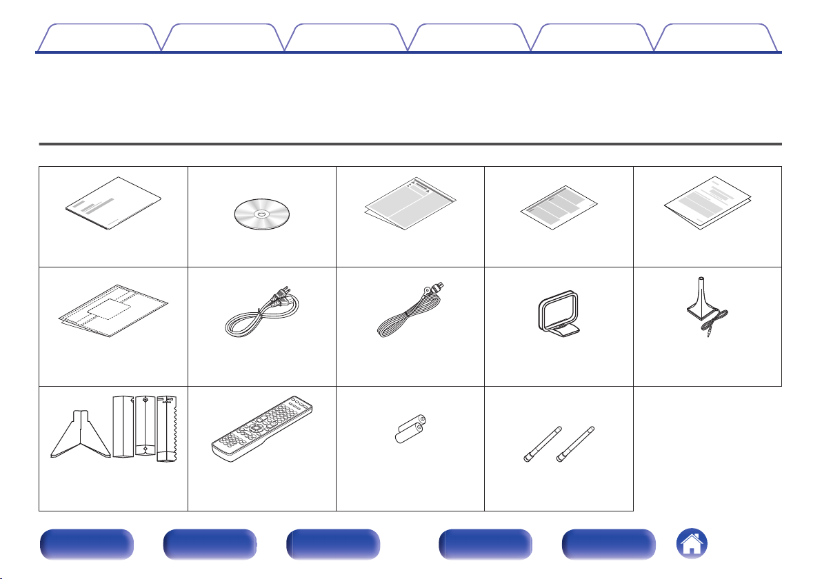
Accessories
Check that the following parts are supplied with the product.
.
.
Quick Start Guide CD-ROM
.
Safety Instructions Notes on radio Warranty (for North America
. .
(Owner’s Manual)
. . . . .
Cable labels
. .
Sound calibration
microphone stand
Power cord FM indoor antenna AM loop antenna Sound calibration
Remote control unit
(RC-1193)
.
R6P/AA batteries External antennas for
.
Bluetooth/wireless
connectivity
Front panel Display Rear panel Remote Index
8
model only)
microphone
(ACM1HB)
R6P/AA batteries
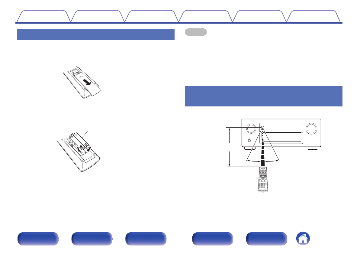
30°
Approx. 23 ft/7 m
30°
Contents
Connections Playback Settings Tips Appendix
Inserting the batteries
Slide the rear cover off the remote control unit in the
1
arrow direction.
Insert two batteries correctly into the battery
2
compartment as indicated.
Put the rear cover back on.
3
NOTE
To prevent damage or leakage of battery fluid:
0
Do not use a new battery together with an old one.
0
Do not use two different types of batteries.
0
Remove the batteries from the remote control unit if it will not be in use for long
0
periods.
If the battery fluid should leak, carefully wipe the fluid off the inside of the battery
0
compartment and insert new batteries.
Operating range of the remote control
.
.
unit
Point the remote control unit at the remote sensor when operating it.
.
Front panel Display Rear panel Remote Index
9
Contents
Connections Playback Settings Tips Appendix
Features
High quality sound
With discrete circuit technology, the power amplifier provides
0
identical quality for all 7-channels (165 Watts x 7-channels)
For optimum realism and stunning dynamic range, the power amplifier
section features discrete power devices (not integrated circuitry).
By using high current, high power discrete power devices, the amplifier
is able to easily drive high quality speakers.
Dolby Atmos (v
0
This unit is equipped with a decoder that supports Dolby Atmos, a
completely new audio format. The placement or movement of sound is
accurately reproduced by the addition of overhead speakers, enabling
you to experience an incredibly natural and realistic surround sound
field.
0
Audyssey DSX® (v
This unit is equipped with Audyssey DSX® processor. By connecting
front height speakers to this unit and playing back with Audyssey DSX
processing you can experience a more vertically expansive front
soundstage. By connecting two front wide speakers, you can
experience a wider and more expanded front soundstage.
Audyssey LFC™ (Low Frequency Containment) (v
0
Audyssey LFC™ solves the problem of low frequency sounds
disturbing people in neighboring rooms or apartments. Audyssey
LFC™ dynamically monitors the audio content and removes the low
frequencies that pass through walls, floors and ceilings. It then applies
psychoacoustic processing to restore the perception of low bass for
listeners in the room. The result is great sound that no longer disturbs
the neighbors.
p. 292)
p. 177)
p. 176)
Discrete subwoofers and Audyssey Sub EQ HT™ (v p. 198)
0
The unit has two subwoofer output capability and can adjust the level
and delay for each subwoofer individually.
Audyssey Sub EQ HT™ makes the integration seamless by first
compensating for any level and delay differences between the two
subwoofers and then applying Audyssey MultEQ® XT32 to both
subwoofers together for improved deep bass response and detail.
DTS Neo:X (v p. 130)
0
This technology enables the playback of 2-channel source audio or
7.1/5.1 multi-channel source audio through a maximum 9.1-channel
speakers, achieving an even broader soundstage.
Denon’s unique high quality playback technology “Denon Link
0
HD” (v
This unit is equipped with our exclusive “Denon Link HD” technology.
When connected to a Denon disc player that has Denon Link HD, the
sound localization becomes more precise, with increased detail and
®
definition. The system works by carrying the critical clock timing signals
via the dedicated Denon Link HD connection, minimizing the jitter
caused by conventional digital connections. This effect can be applied
to an audio source of any media from a Blu-ray disc player.
p. 58)
Front panel Display Rear panel Remote Index
10
4K 60p
4:4:4
4K 60p
4:4:4
60
p
:4
4K 4K
Up to 1080p
4K
Up scaling
Contents
Connections Playback Settings Tips Appendix
High performance
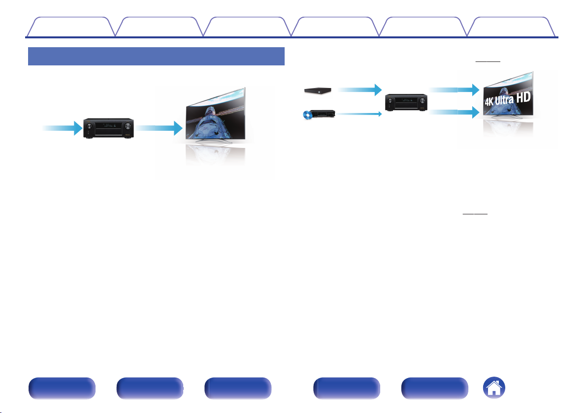
4K 60Hz input/output supported
0
.
When 4K Ultra HD (High Definition) is used, an input/output speed of 60
frames per second (60p) is achieved for video signals. When connected
to 4K Ultra HD and 60p video signal input compatible TV, you can enjoy
the sense of realism only available from high-definition images, even
when viewing fast-moving video.
This unit also supports image processing for 4K 60p, 4:4:4 and 24-bit
videos. By processing the video at the original resolution, this unit lets
you enjoy flawless, high-definition picture quality.
Digital video processor upscales analog video signals (SD
0
resolution) to HD (720p/1080p) and 4K (v
.
p. 189)
This unit is equipped with a 4K video upscaling function that allows
analog video or SD (Standard Definition) video to be output via HDMI at
4K (3840 × 2160 pixels) resolution. This function enables the device to
be connected to a TV using a single HDMI cable, and produces high
definition images for any video source.
Equipped with HDMI ZONE2 output (v p. 153)
0
The ZONE2 multi-room output includes an HDMI output that lets you
enjoy a different A/V source in that room, with another program playing
in the main room.
Front panel Display Rear panel Remote Index
11
83
/
Out
In
Contents
Connections Playback Settings Tips Appendix
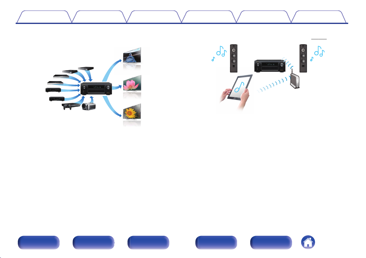
HDMI connections enable connection to various digital AV
0
devices (8 inputs, 3 output)
.
For connection to a broad range of digital sources, this unit features 8
HDMI inputs, including 1 on the front panel that lets you quickly and
conveniently connect a camcorder, game console or other HDMIequipped device. There are dual HDMI outputs for the main room, and a
third HDMI output for another room.
0
The device is equipped with a AirPlay® function in addition to
network functions such as Internet radio etc. (v
.
You can enjoy a wide variety of content, including listening to Internet
Radio, playing audio files stored on your PC, and displaying
photographs stored on your PC on our television.
This unit also supports Apple AirPlay which lets you stream your music
library from an iPhone®, iPad®, iPod touch® or iTunes®.
Playback of DSD and FLAC files via USB and networks
0
This unit supports the playback of high resolution audio formats such as
DSD (2.8 MHz) and FLAC 192 kHz files. It provides high quality
playback of high resolution files.
p. 116)
Front panel Display Rear panel Remote Index
12
【MAIN ZONE】【ZONE2】/【ZONE3】
Contents
Connections Playback Settings Tips Appendix
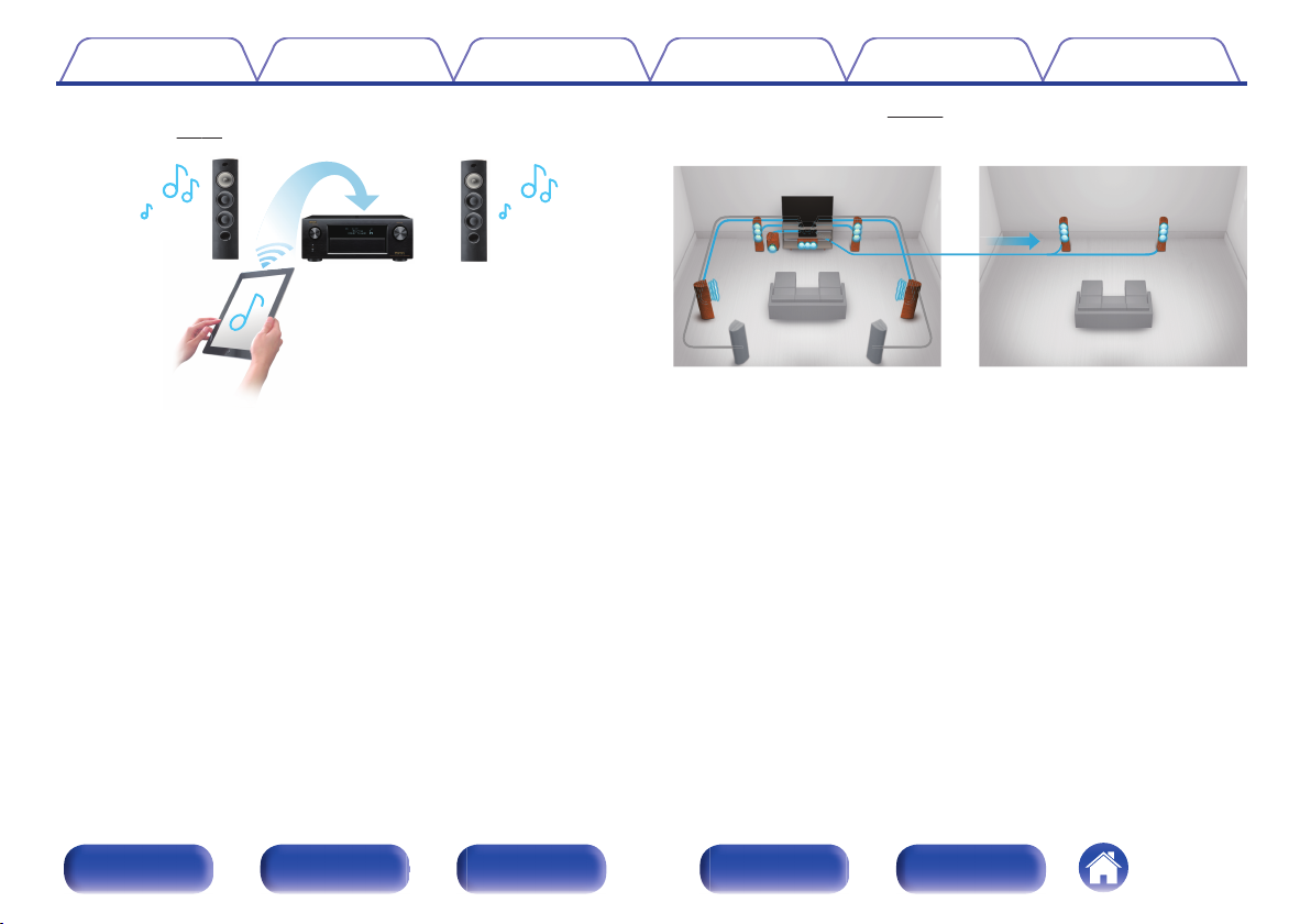
Wireless connection with Bluetooth devices can be carried out
0
easily (v p. 81)
.
You can enjoy music simply by connecting wirelessly with your
smartphone, tablet, PC, etc.
0
Compatible with the “Denon Remote App”z for performing basic
operations of the unit with an iPad, iPhone or Android™ devices
(Google, Amazon Kindle Fire)
“Denon Remote App” is application software that allows you to perform
basic operations with an iPad, iPhone, Android smartphone or Android
tablet such as turning the unit ON/OFF, controlling the volume, and
switching the source.
Download the appropriate “Denon Remote App” for your iOS or Android
z
devices. This unit needs to be connected to the same LAN or Wi-Fi (wireless
LAN) network that the iPhone or iPod touch is connected to.
Multi-Room audio (v p. 129)
0
.
You can select and play back the respective inputs in MAIN ZONE,
ZONE2 and ZONE3.
In addition, when the All Zone Stereo function is used, the music being
played back in MAIN ZONE can be enjoyed in all the zones at the same
time. This is useful when you want to let the BGM propagate throughout
the whole house.
Energy-saving design
0
This unit is equipped with an ECO Mode function that allows you to
enjoy music and movies while reducing the power consumption during
use, and also an auto-standby function that automatically turns off the
power supply when the unit is not in use. This helps reduce
unnecessary power use.
Front panel Display Rear panel Remote Index
13
Contents Connections Playback Settings Tips Appendix
Easy operation
“Setup Assistant” provides easy-to-follow setup instructions
0
First select the language when prompted. Then simply follow the
instructions displayed on the TV screen to set up the speakers, network,
etc.
Easy to use Graphical User Interface
0
This unit is equipped with a Graphical User Interface for improved
operability.
Front panel Display Rear panel Remote Index
14
u
wqtre y
Contents Connections Playback Settings Tips Appendix
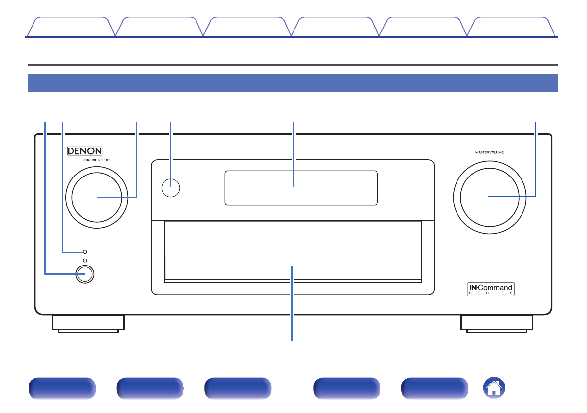
Part names and functions
Front panel
A B C D E F
.
Front panel Display Rear panel Remote Index
G
15
ewqrt y
u
Contents
.
Power operation button (X)
A
Connections Playback Settings Tips Appendix
Used to turn the power of the MAIN ZONE (room where this unit is
located) on/off (standby). (v
Power indicator
B
p. 71)
This is lit as follows according to the power status:
White: Power on
0
Off: Normal standby
0
Red:
0
When “HDMI Pass Through” is set to “On” (v
0
When “HDMI Control” is set to “On” (v
0
When “IP Control” is set to “Always On” (v p. 231)
0
p. 184)
p. 184)
SOURCE SELECT knob
C
This selects the input source. (v
Remote control sensor
D
p. 71)
This receives signals from the remote control unit. (v p. 9)
Display
E
This displays various pieces of information. (v
MASTER VOLUME knob
F
This adjusts the volume level. (v
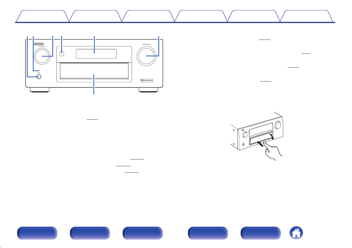
Door
G
p. 72)
p. 19)
When you are using buttons and/or connectors behind the door, press
the bottom of the door to open it. Be careful not to catch your fingers
when closing the door.
.
Front panel Display Rear panel Remote Index
16
io Q0qw rtyue
Contents
Connections Playback Settings Tips Appendix
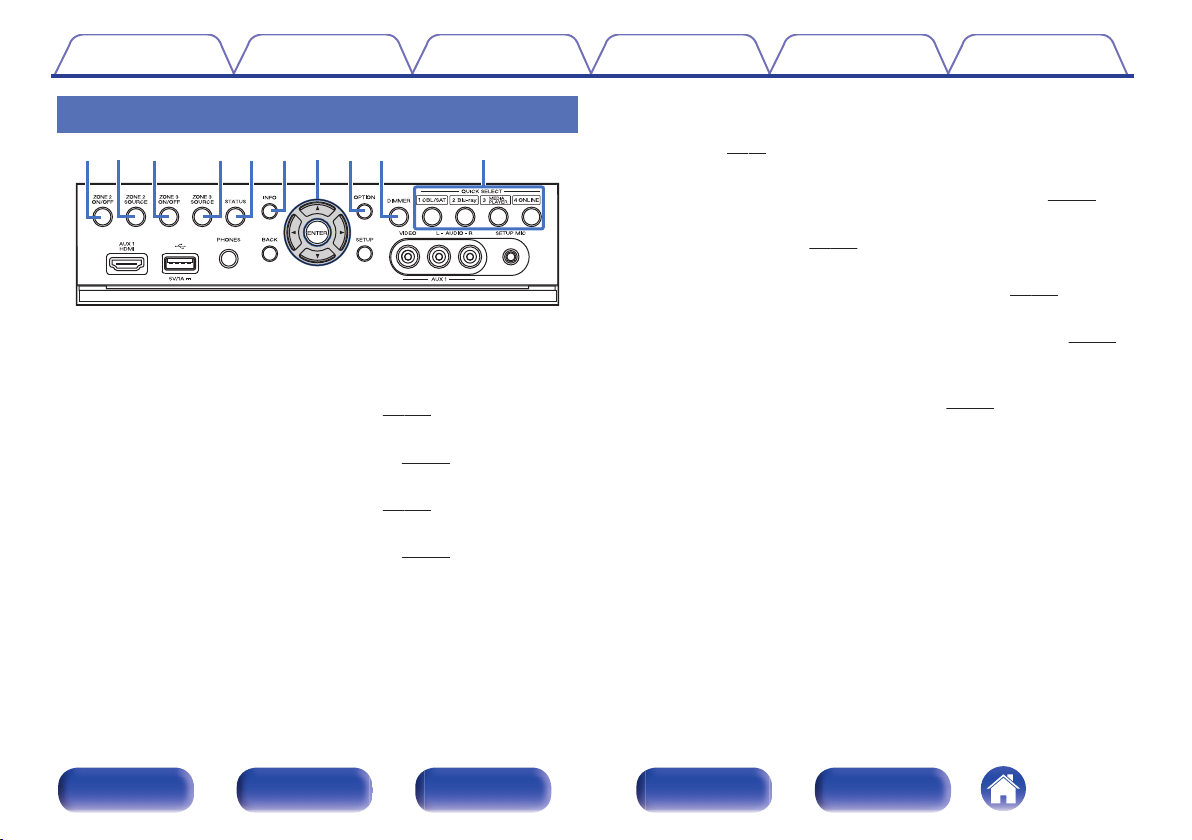
With the door open
.
ZONE2 ON/OFF button
A
This turns the power of ZONE2 on/off. (v
ZONE2 SOURCE button
B
This selects the input source for ZONE2. (v p. 158)
ZONE3 ON/OFF button
C
This turns the power of ZONE3 on/off. (v
ZONE3 SOURCE button
D
This selects the input source for ZONE3. (v
p. 158)
p. 158)
p. 158)
STATUS button
E
Each press of this switches the status information that is shown on the
display. (v p. 75)
Information button (INFO)
F
This displays the status information on the TV screen. (v
Cursor buttons (uio p)
G
These select items. (v
OPTION button
H
This displays the option menu on the TV screen. (v p. 120)
DIMMER button
I
Each press of this switches the brightness of the display. (v
QUICK SELECT buttons
J
These call up settings registered to each button, such as input source,
volume level and sound mode settings. (v
p. 163)
p. 148)
p. 240)
p. 239)
Front panel Display Rear panel Remote Index
17
Q3Q
4
Q
8
Q1Q
2
Q
7
Q
6Q5
Contents Connections Playback Settings Tips Appendix
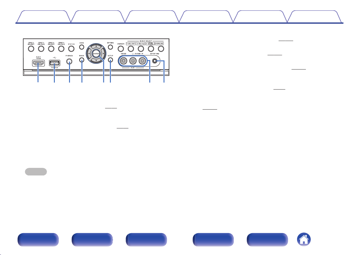
BACK button
N
p. 163)
p. 163)
p. 59)
.
AUX1 HDMI connector
K
This is used to connect HDMI output compatible devices such as video
camcorders and game consoles. (v p. 59)
USB port
L
This is used to connect USB storages (such as USB memory devices)
and the USB cable supplied with iPod. (v p. 61)
Headphones jack (PHONES)
M
This is used to connect headphones.
When the headphones are plugged into this jack, audio will no longer
be output from the connected speakers or from the PRE OUT
connectors.
NOTE
To prevent hearing loss, do not raise the volume level excessively when using
headphones.
This returns to the previous screen. (v
ENTER button
O
This determines the selection. (v p. 163)
SETUP button (SETUP)
P
This displays the menu on the TV screen. (v
AUX1 INPUT connector
Q
Used to connect analog output compatible devices such as video
camcorders and game consoles. (v
SETUP MIC jack
R
This is used to connect the supplied Sound calibration microphone.
(v p. 200)
Front panel Display Rear panel Remote Index
18
Q
0
Q1Q
2
iuoyt
rewq
Contents Connections Playback Settings Tips Appendix
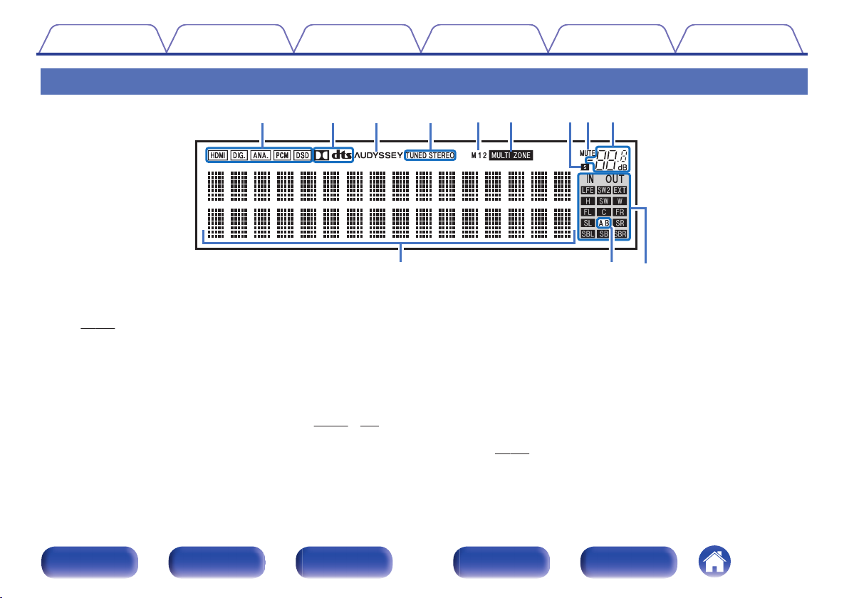
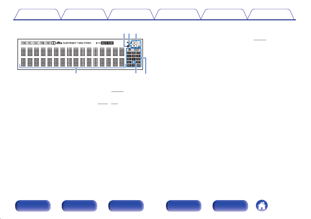
Display
H I
G
.
Input signal indicators
A
The respective indicator will light corresponding to the input signal.
(v p. 196)
Decoder indicators
B
These light when Dolby or DTS signals are input or when the Dolby or
DTS decoder is running.
C
Audyssey® indicator
This lights when “MultEQ® XT32”, “Dynamic EQ”, “Dynamic Volume”,
“Audyssey DSX®” or “Audyssey LFCTM” is set. (v
p. 174 - 177)
Front panel Display Rear panel Remote Index
J
Tuner reception mode indicators
D
These light up according to the reception conditions when the input
source is set to “Tuner”.
TUNED: Lights up when the broadcast is properly tuned in.
STEREO: Lights up when receiving FM stereo broadcasts.
Monitor output indicator
E
These light according to the HDMI monitor output setting. When set to
“Auto(Dual)”, the indicators light according to connection status.
MULTI ZONE indicator
F
This lights up when ZONE2 or ZONE3 (separate room) power is turned
on. (v
19
p. 158)
K
L
Q0 Q1 Q2
iuo
Contents Connections Playback Settings Tips Appendix
Input/output signal channel indicators
L
The channel for input/output signals is displayed according to the
setting configured for “Channel Indicators”. (v p. 239)
When “Channel Indicators” is set to “Output” (Default)
0
These light when audio signals are being output from the speakers.
When “Channel Indicators” is set to “Input”
0
These light corresponding to the channels that include the input
signals.
.
Sleep timer indicator
G
This lights when the sleep mode is selected. (v
MUTE indicator
H
This blinks while the sound is muted. (v
Volume indicator
I
Information display
J
p. 147)
p. 72, 159)
The input source name, sound mode, setting values and other
information are displayed here.
Front speaker indicator
K
This lights according to the setting of the front A and B speakers.
When playing HD Audio sources, the A indicator lights when a
signal from an extension channel (a channel other than the front,
center, surround, surround back, front height, front wide or LFE
channel) is input.
Front panel Display Rear panel Remote Index
20
CENTER SURROUND
SURROUND BACK
SURROUNDFRONT
SURROUND BACK
FRONT
HEIGHT1 HEIGHT1
q
Q2 Q3 Q4 Q5 Q6
wytrue
oiQ0 qQ1
Contents Connections Playback Settings Tips Appendix
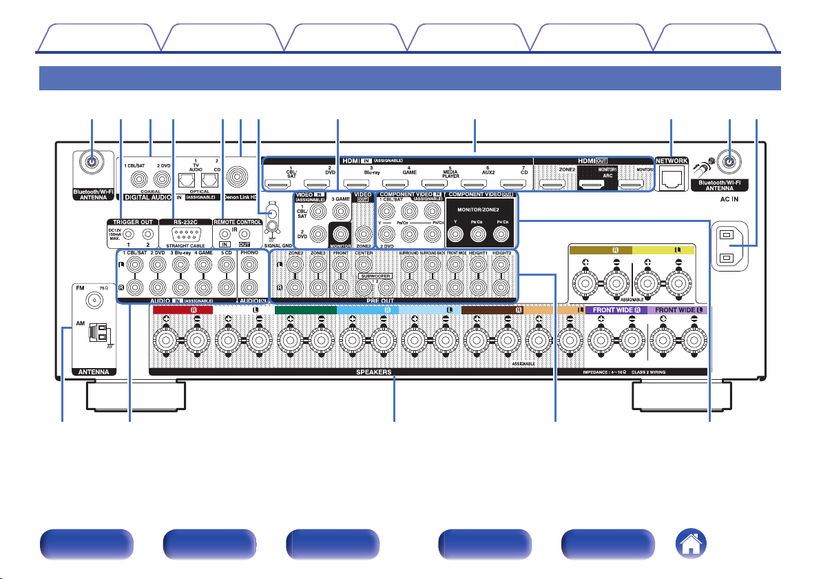
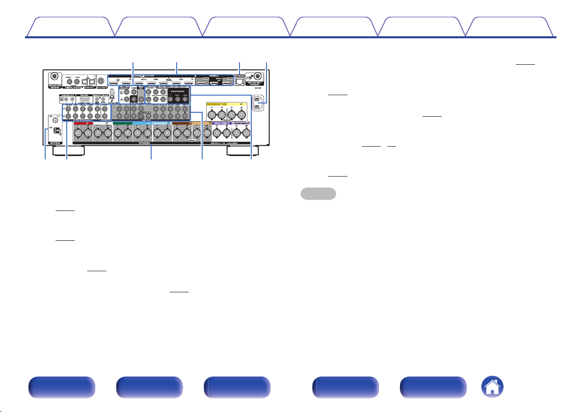
Rear panel
A B C D E F G H I J A K
L M N O P
.
Front panel Display Rear panel Remote Index
21
CENTER SURROUND
SURROUND BACK
SURROUNDFRONT
SURROUND BACK
FRONT
HEIGHT1 HEIGHT1
qw ytrue
q
CENTER SURROUND
SURROUND BACK
SURROUNDFRONT
SURROUND BACK
FRONT
HEIGHT1 HEIGHT1
qwe
Contents
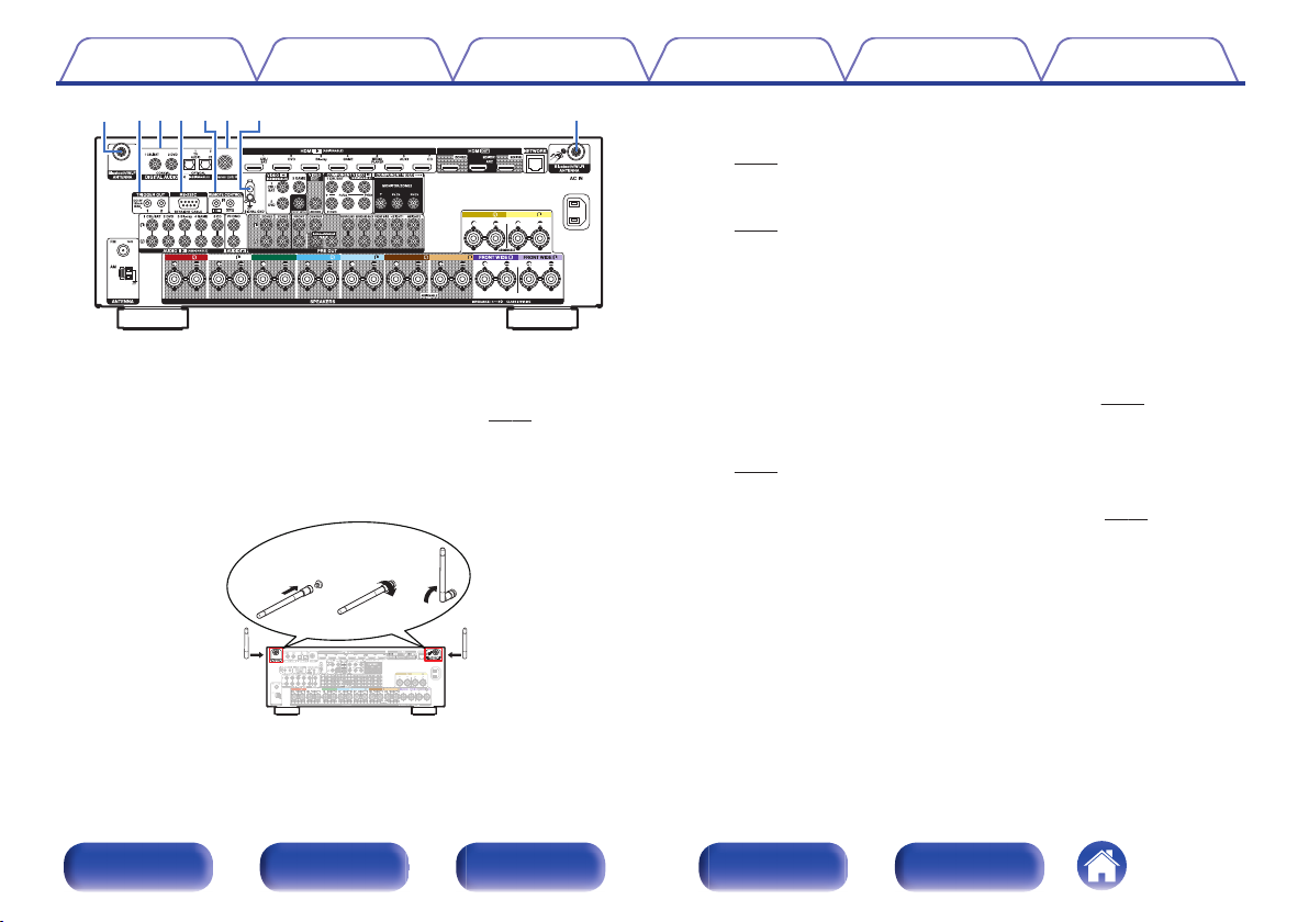
.
Bluetooth/wireless LAN antenna connectors
A
Connections Playback Settings Tips Appendix
Used to connect the included external antennas for Bluetooth/wireless
connectivity when connecting to a network via wireless LAN, or when
connecting to a handheld device via Bluetooth. (v
Place the external antennas for Bluetooth/wireless connectivity
A
p. 66)
evenly over the screw terminal of rear.
Turn clockwise until the antennas is fully connected.
B
Rotate the antenna upwards for best reception.
C
TRIGGER OUT jacks
B
Used to connect devices equipped with the trigger function.
(v
p. 68)
Digital audio connectors (DIGITAL AUDIO)
C
Used to connect devices equipped with digital audio connectors.
p. 53)
(v
RS-232C connector
D
Used to connect home automation controller devices fitted with
RS-232C connectors. Consult the owner’s manual of the home
automation controller for more information about serial control of this
unit.
REMOTE CONTROL jacks
E
Used to connect infrared receivers/transmitters in order to operate this
unit and external devices from a different room. (v
Denon Link HD connector
F
p. 67)
Used to connect a Denon Link HD compatible Blu-ray Disc player.
(v
p. 58)
SIGNAL GND terminal
G
Used to connect a ground wire for the turntable. (v p. 60)
Front panel Display Rear panel Remote Index
.
22
CENTER SURROUND
SURROUND BACK
SURROUNDFRONT
SURROUND BACK
FRONT
HEIGHT1 HEIGHT1
Q2Q
3
Q
4
Q
5
Q
6
oQ0 Q1i
Contents Connections Playback Settings Tips Appendix
FM/AM antenna terminals (ANTENNA)
L
Used to connect FM antennas and AM loop antennas. (v p. 63)
Analog audio connectors (AUDIO)
M
Used to connect devices equipped with analog audio connectors.
(v p. 56)
Speaker terminals (SPEAKERS)
N
Used to connect speakers. (v
PRE OUT connectors
O
p. 35)
Used to connect a subwoofer with built-in amplifier or an external power
p. 36, 50)
.
Video connectors (VIDEO)
H
Used to connect devices equipped with video connectors.
(v p. 54)
HDMI connectors
I
amplifier. (v
Component video connectors (COMPONENT VIDEO)
P
Used to connect devices equipped with component video connectors.
(v p. 54)
NOTE
Do not touch the inner pins of the connectors on the rear panel. Electrostatic
discharge may cause permanent damage to the unit.
Used to connect devices equipped with HDMI connectors.
(v p. 52)
NETWORK connector
J
Used to connect to a LAN cable when connecting to a wired LAN
network. (v
AC inlet (AC IN)
K
p. 65)
Used to connect the power cord. (v p. 69)
Front panel Display Rear panel Remote Index
23
SOUND MODE
SOUND MODE
POWER
POWER
AVR CONTROL
AVR CONTROL
QUICK SELECT
QUICK SELECT
TUNE
TUNE
TUNE
TUNE
PURE
PURE
MOVIE
MOVIE
GAME
GAME
MUSIC
MUSIC
GAME
GAME
CB
CBL/
SAT
Blu-ray
Blu-ray
DVDVD
AUX1
AUX1
AUX2
AUX2
INTERNET
R
ADIO
ADIO
iPo
iPod/
USB
USB
VOLUME
VOLUME
OPTION
OPTION
INFO
INFO
BACK
BACK
SETUP
SETUP
CH/
PAGE
PAGE
MENU
MENU
Z2
Z 3
Z 3
1
1 2 3 4
2 3
4 5 6
7 8 9
ENTER
ENTER
0
+10
+10
GHI
GHI
JKL
JKL
MNO
MNO
PQRS
PQR S
TUV
TUV
ABC
ABC
. /
. /
DEF
DEF
SLEEPEP
WXYZ
WXY Z
MAIN
MAIN
PHONO
PHONO
DEV.V. T V AVR
DEVICE
DEVICE TV
MEDIAIA
PLAYERER
ONLINE
ONLINE
MUSIC
MUSIC
CD
CD
Bluetooth
Bluetooth
TUNER
TUNER
TV
AUDIO
AUDIO
MENU
MENU
INP
INPUT
MUTE
MUTE
ECO
ECO
ENTER
ENTER
q
w
e
r
y
u
t
Contents
Connections Playback Settings Tips Appendix
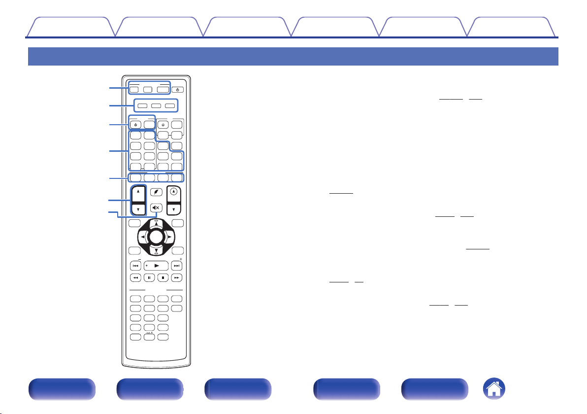
Remote control unit
AVR operation buttons (AVR CONTROL MAIN, Z2, Z3)
A
These switch the zone (MAIN ZONE, ZONE2, ZONE3) that is operated
through the remote control unit. (v p. 158, 163)
Operation mode indicators
B
The “AVR” operation mode indicator lights when the unit is being
operated.
The “DEV.” indicator lights when an external device is being operated.
The “TV” indicator lights when the TV is being operated.
Device operation buttons (DEVICE X / DEVICE MENU)
C
These turn the power of external devices on/off and call up menus.
Preset codes need to be registered in order to use these buttons.
p. 246)
(v
Input source select buttons
D
These select the input source. (v p. 71, 158)
QUICK SELECT buttons (1 – 4)
E
These call up settings registered to each button, such as input source,
volume level and sound mode settings. (v
Channel/page search buttons (CH/PAGE df)
F
p. 148)
These select radio stations registered to presets or switch pages.
(v
p. 75, 90)
MUTE button (:)
G
This mutes the output audio. (v p. 72, 158)
.
24
Front panel Display Rear panel Remote Index
SOUND MODE
SOUND MODE
POWER
POWER
AVR CONTROL
AVR CONTROL
QUICK SELECT
QUICK SELECT
TUNE
TUNE
TUNE
TUNE
PURE
PURE
MOVIE
MOVIE
GAME
GAME
MUSIC
MUSIC
GAME
GAME
CB
CBL/
SAT
Blu-ray
Blu-ray
DVDVD
AUX1
AUX1
AUX2
AUX2
INTERNET
R
ADIO
ADIO
iPo
iPod/
USB
USB
VOLUME
VOLUME
OPTION
OPTION
INFO
INFO
BACK
BACK
SETUP
SETUP
CH/
PAGE
PAGE
MENU
MENU
Z2
Z 3
Z 3
1
1 2 3 4
2 3
4 5 6
7 8 9
ENTER
ENTER
0
+10
+10
GHI
GHI
JKL
JKL
MNO
MNO
PQRS
PQR S
TUV
TUV
ABC
ABC
. /
. /
DEF
DEF
SLEEPEP
WXYZ
WXY Z
MAIN
MAIN
PHONO
PHONO
DEV.V. T V AVR
DEVICE
DEVICE TV
MEDIAIA
PLAYERER
ONLINE
ONLINE
MUSIC
MUSIC
CD
CD
Bluetooth
Bluetooth
TUNER
TUNER
TV
AUDIO
AUDIO
MENU
MENU
INP
INPUT
MUTE
MUTE
ECO
ECO
ENTER
ENTER
Q4
Q3
Q1
Q2
i
o
Q0
Contents
Connections Playback Settings Tips Appendix
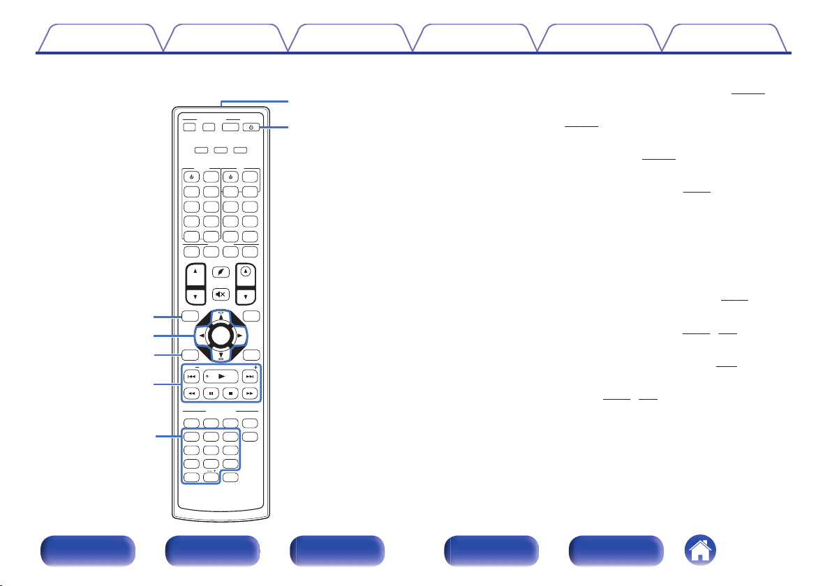
Information button (INFO)
H
This displays the status information on the TV screen. (v
Cursor buttons (uio p)
I
These select items. (v p. 163)
BACK button
J
This returns to the previous screen. (v
System buttons
K
These perform playback related operations. (v
Skip buttons (8, 9)
0
Play button (1)
0
Search buttons (6, 7)
0
Pause button (3)
0
Stop button (2)
0
Tuning up / Tuning down buttons (TUNE +, –)
These select either FM broadcast or AM broadcast. (v p. 87)
Number / Character buttons
L
These enter letters or numbers into the unit. (v p. 87, 165)
Remote control signal transmitter
M
This transmits signals from the remote control unit. (v p. 9)
POWER button (X)
N
This turns the power on/off. (v p. 71, 158)
.
25
Front panel Display Rear panel Remote Index
p. 240)
p. 163)
p. 75)
SOUND MODE
SOUND MODE
POWER
POWER
AVR CONTROL
AVR CONTROL
QUICK SELECT
QUICK SELECT
TUNE
TUNE
TUNE
TUNE
PURE
PURE
MOVIE
MOVIE
GAME
GAME
MUSIC
MUSIC
GAME
GAME
CB
CBL/
SAT
Blu-ray
Blu-ray
DVDVD
AUX1
AUX1
AUX2
AUX2
INTERNET
R
ADIO
ADIO
iPo
iPod/
USB
USB
VOLUME
VOLUME
OPTION
OPTION
INFO
INFO
BACK
BACK
SETUP
SETUP
CH/
PAGE
PAGE
MENU
MENU
Z2
Z 3
Z 3
1
1 2 3 4
2 3
4 5 6
7 8 9
ENTER
ENTER
0
+10
+10
GHI
GHI
JKL
JKL
MNO
MNO
PQRS
PQR S
TUV
TUV
ABC
ABC
. /
. /
DEF
DEF
SLEEPEP
WXYZ
WXY Z
MAIN
MAIN
PHONO
PHONO
DEV.V. T V AVR
DEVICE
DEVICE TV
MEDIAIA
PLAYERER
ONLINE
ONLINE
MUSIC
MUSIC
CD
CD
Bluetooth
Bluetooth
TUNER
TUNER
TV
AUDIO
AUDIO
MENU
MENU
INP
INPUT
MUTE
MUTE
ECO
ECO
ENTER
ENTER
W0
W1
W2
Q9
Q7
Q8
Q9
Q5
Q6
Contents
Connections Playback Settings Tips Appendix
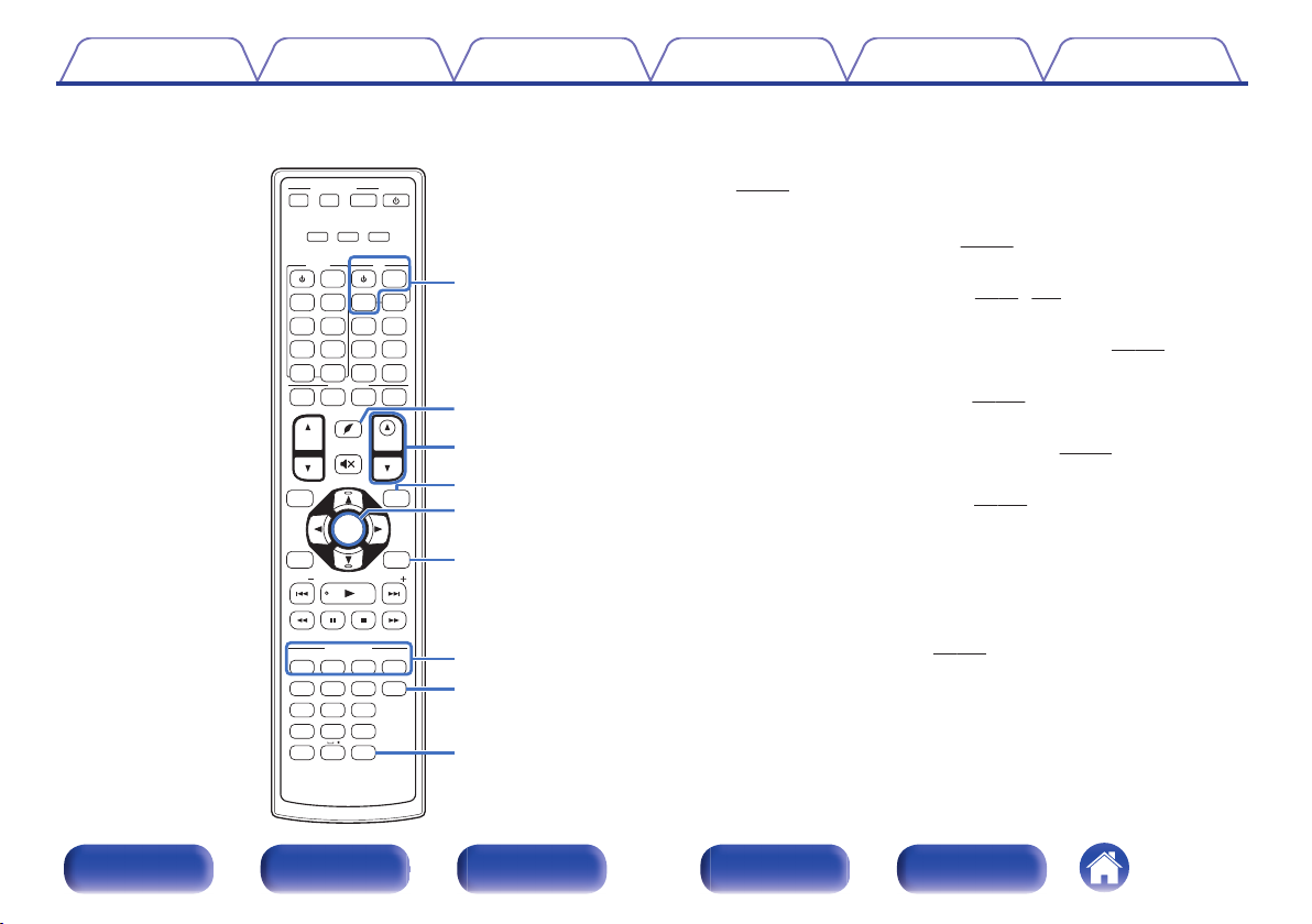
TV operation buttons (TV X / TV MENU / TV INPUT)
O
These turn the TV power on/off, switch the TV input and call up menus.
Preset codes need to be registered in order to use these buttons.
(v p. 249)
P
ECO Mode button (G)
This switches to ECO Mode. (v
VOLUME buttons (df)
Q
These adjust the volume level. (v p. 72, 159)
OPTION button
R
This displays the option menu on the TV screen. (v p. 120)
ENTER button
S
This determines the selection. (v
SETUP button
T
This displays the menu on the TV screen. (v p. 163)
SOUND MODE buttons
U
These select the sound mode. (v
MOVIE button
0
MUSIC button
0
GAME button
0
PURE button
0
SLEEP button
V
This sets the sleep timer. (v
p. 234)
p. 163)
p. 130)
p. 146)
.
26
Front panel Display Rear panel Remote Index
R
L
R
L
Contents Connections Playback Settings Tips Appendix
Connections
Contents
o
Connecting speakers 28
Connecting a TV 51
Connecting a playback device 55
Connecting an iPod or USB memory device to the USB port 61
Connecting an FM/AM antenna 63
Connecting to a home network (LAN) 65
Connecting an external control device 67
Connecting the power cord 69
NOTE
Do not plug in the power cord until all connections have been completed.
0
However, when the “Setup Assistant” is running, follow the instructions in the
“Setup Assistant” (page 9 in the separate “Quick Start Guide”) screen for making
connections. (During “Setup Assistant” operation, the input/output connectors do
not conduct current.)
Do not bundle power cords together with connection cables. Doing so can result in
0
noise.
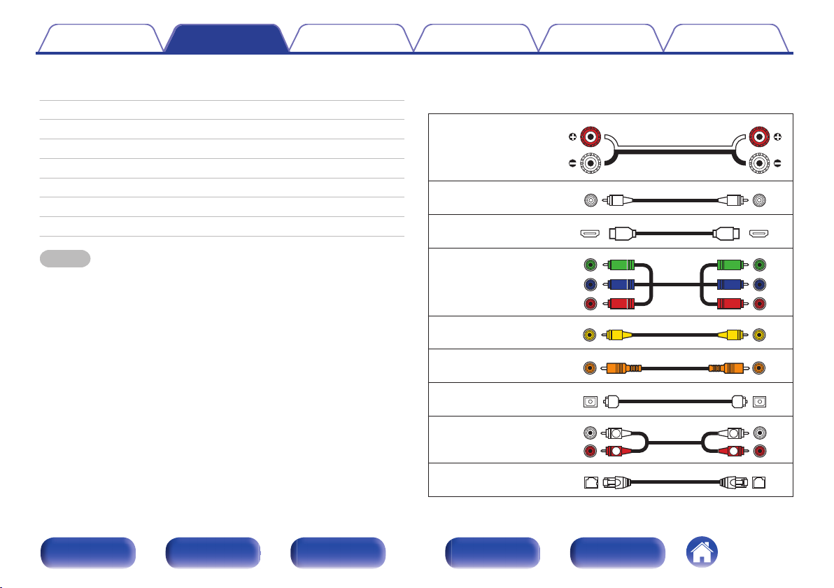
Cables used for connections
o
Provide necessary cables according to the devices you want to
connect.
Speaker cable
.
Subwoofer cable
HDMI cable
.
.
Component video cable
.
Video cable
Coaxial digital cable
Optical cable
.
.
.
Audio cable
.
LAN cable
Front panel Display Rear panel Remote Index
27
.
C
FL FR
SBL
SBR
SB
SW1
SW2
FWL
FWR
SL SR
Contents
Connections Playback Settings Tips Appendix
Connecting speakers
Install speakers and connect them to this unit. (v p. 28, 35)
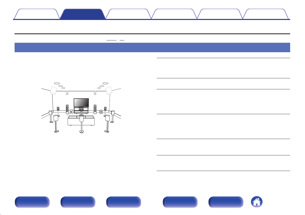
Speaker installation
Determine the speaker system depending on the number of speakers you
are using and install each speaker and subwoofer in the room.
Speaker installation is explained using this example of a typical
installation.
FL/FR (Front
speaker left/right):
C (Center
speaker):
SL/SR (Surround
speaker left/right):
SBL/SBR
(Surround back
.
speaker left/right):
FWL/FWR
(Front wide speakers left/
right):
SW 1/2 (Subwoofer) :
Front panel Display Rear panel Remote Index
28
Place the FRONT left and right speakers an equal
distance from the main listening position. The distance
between each speaker and your TV should also be the
same.
Place the CENTER speaker in between the front
speakers and above or below your TV.
Place the SURROUND left and right speakers an
equal distance to the left and right sides of the main
listening position. If you don’t have surround back
speakers, move the surround speakers slightly behind
your listening position.
Place the SURROUND BACK left and right speakers
an equal distance from the main listening position and
directly behind the main listening position. When using
a single surround back speaker (SB), place it directly
behind the listening position.
Place the FRONT WIDE left and right speakers
outside of the front left and right speakers so that there
is an equal distance between all front speakers.
Place the SUBWOOFER at a convenient location near
the front speakers. If you have two subwoofers, place
them asymmetrically across the front of your room.
FHL FHR
TRR
TRL
TFR
TFL
RHL RHR
TMR
TML
Contents Connections Playback Settings Tips Appendix
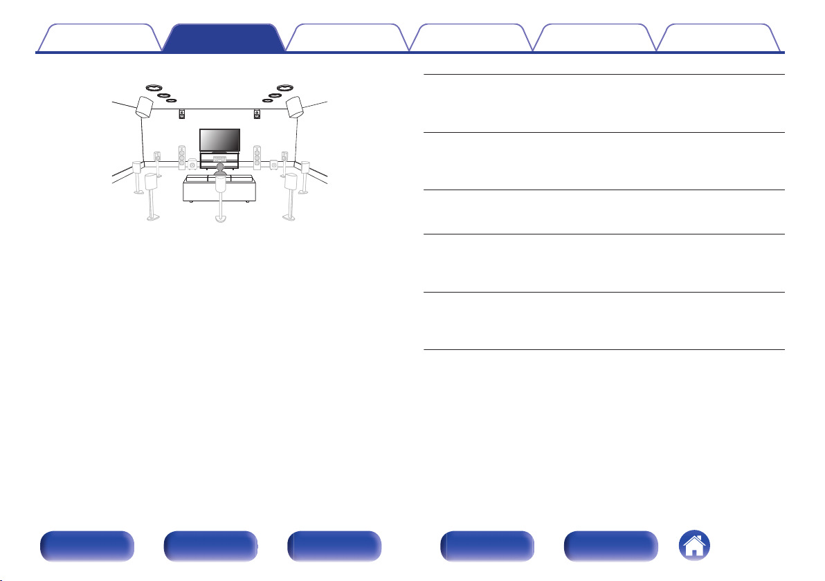
.
FHL/FHR (Front
height speaker left/
right):
TFL/TFR (Top front
speaker left/right):
TML/TMR (Top
middle speaker left/
right):
TRL/TRR (Top rear
speaker left/right):
RHL/RHR (Rear
height speaker left/
right):
Place the FRONT HEIGHT left and right speakers
directly above the front speakers. Mount them as
close to the ceiling as possible and aim them
towards the main listening position.
Mount the TOP FRONT left and right speakers on
the ceiling slightly in front of your main listening
position and aligned with the left and right front
speakers.
Mount the TOP MIDDLE left and right speakers
directly above the main listening position and
aligned with the left and right front speakers.
Mount the TOP REAR left and right speakers on
the ceiling slightly behind your main listening
position and aligned with the left and right front
speakers.
Place the REAR HEIGHT left and right speakers
directly behind the main listening position. Mount
them as close to the ceiling as possible and
aligned with the left and right front speakers.
Front panel Display Rear panel Remote Index
29
FDL FDR
BDL BDR
SDL SDR
Contents Connections Playback Settings Tips Appendix
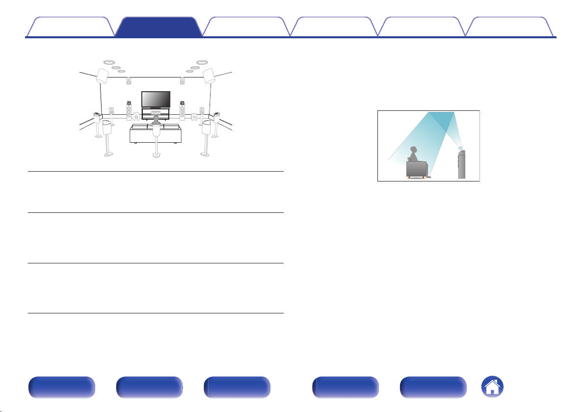
About Dolby enabled speakers
Dolby enabled speakers reflect the sound off the ceiling to allow the sound
to come from over your head by using a special upward-pointing speaker
that is placed on the floor.
You can enjoy the Dolby Atmos 3D sound even in an environment where
speakers cannot be installed on the ceiling.
.
FDL/FDR (Front
Dolby speaker left/
right):
Place the FRONT DOLBY ENABLED speaker on
the front speaker. For a Dolby enabled speaker
integrated with a front speaker, place the Dolby
enabled speaker instead of the front speaker.
.
Place the SURROUND DOLBY ENABLED speaker
SDL/SDR (Surround
Dolby speaker left/
right):
on the surround speaker. For a Dolby enabled
speaker integrated with a surround speaker, place
the Dolby enabled speaker instead of the surround
speaker.
Place the BACK DOLBY ENABLED speaker on the
BDL/BDR (Back
Dolby speaker left/
right):
surround back speaker. For a Dolby enabled
speaker integrated with a surround back speaker,
place the Dolby enabled speaker instead of the
surround back speaker.
Front panel Display Rear panel Remote Index
30
 Loading...