


Contents Connections Playback Settings Tips Appendix
AVR-S570BT
AV SURROUND RECEIVER
Owner’s Manual
Front panel Display Rear panel Remote Index
1

Contents Connections Playback Settings Tips Appendix
Accessories
Inserting the batteries
Operating range of the remote control unit
Features
High quality sound
High performance
Easy operation
Part names and functions
Front panel
Display
Rear panel
Remote control unit
Connections
Speaker installation
Connecting speakers
Before connecting speakers
Standard connection
Connecting a TV
Connection 1 : TV equipped with an HDMI connector and
compatible with the ARC / eARC
Connection 2 : TV equipped with an HDMI connector and
incompatible with the ARC / eARC
6
Connecting a playback device
7
Connecting a set-top box (Satellite tuner/cable TV)
7
Connecting a media player
8
Connecting a Blu-ray Disc player or DVD player
8
Connecting a game console
8
Connecting a USB memory device to the USB port
10
Connecting an FM/AM antenna
11
Connecting the power cord
11
Playback
14
15
Basic operation
17
21
23
23
26
27
28
29
Turning the power on
Selecting the input source
Adjusting the volume
Turning off the sound temporarily (Muting)
Playback a Blu-ray Disc player/DVD player
Playing a USB memory device
Playing files stored on USB memory devices
Listening to music on a Bluetooth device
Playing music from Bluetooth device
Pairing with other Bluetooth devices
Reconnecting to this unit from a Bluetooth device
30
31
32
33
34
35
36
38
40
40
40
41
41
41
42
43
44
45
47
48
Front panel Display Rear panel Remote Index
2

Contents Connections Playback Settings Tips Appendix
Listening to FM/AM broadcasts
Listening to FM/AM broadcasts
Tuning in to stations and presetting them automatically (Auto
Preset)
Presetting the current broadcast station (Preset Memory)
Listening to preset stations
Skipping preset broadcast stations (Preset Skip)
Cancelling Preset Skip
Compatible with the “Denon 500 Series Remote” app
Convenience functions
Performing repeat playback (Repeat)
Performing random playback (Random)
Adjusting the tone (Tone)
Adjusting audio delay (Audio Delay)
Optimizing the night time listening volume (Night Mode)
Displaying your desired video during audio playback (Video
Select)
Selecting a sound mode
Selecting a sound mode
HDMI control function
Setting procedure
Adjusting the volume of each channel to match the input source
(Channel Level Adjust)
49
Sleep timer function
50
51
52
52
53
53
54
55
56
56
57
58
58
59
60
60
64
64
65
Using the sleep timer
Quick select plus function
Calling up the settings
Changing the settings
Settings
Menu map
Menu operations
Audio
Surround Parameter
Restorer
Volume
Room EQ
Video
HDMI Setup
HDMI Upscaler
Screen Saver
4K/8K Signal Format
HDCP Setup
66
67
68
69
69
70
73
74
74
77
78
79
80
80
83
84
84
86
Front panel Display Rear panel Remote Index
3

Contents Connections Playback Settings Tips Appendix
Inputs
Input Assign
Source Level
Input Select
Speakers
Auto Setup
Procedure for speaker settings (Auto Setup)
Error messages
Manual Setup
Speaker Layout
Distances
Levels
Crossovers
Advanced Setup
General
Language
ECO
Bluetooth
Quick Select Options
Front Display
Firmware
Setup Lock
Reset
Checking the information
87
87
87
88
89
89
91
93
94
94
95
95
96
97
98
98
98
100
101
102
102
103
103
104
Tips
Tips
Troubleshooting
Power does not turn on / Power is turned off
Operations cannot be performed through the remote control unit
Display on this unit shows nothing
No sound comes out
Desired sound does not come out
Sound is interrupted or noise occurs
No video is shown on the TV
The menu screen is not displayed on the TV
The color of the menu screen and operations content displayed
on the television is different from normal
USB memory devices cannot be played back
File names on the USB memory device are not displayed properly
Bluetooth cannot be played back
The HDMI control function does not work
Resetting factory settings
107
108
109
110
110
111
112
114
115
117
117
118
119
119
120
121
Front panel Display Rear panel Remote Index
4

Contents Connections Playback Settings Tips Appendix
Appendix
About HDMI
Relationship between video signals and monitor output
Playing back a USB memory devices
Playing back a Bluetooth device
Personal memory plus function
Last function memory
Sound modes and channel output
Sound modes and surround parameters
Types of input signals, and corresponding sound modes
Explanation of terms
Trademark information
Specifications
Index
122
126
128
129
130
130
131
132
133
134
139
141
145
Front panel Display Rear panel Remote Index
5
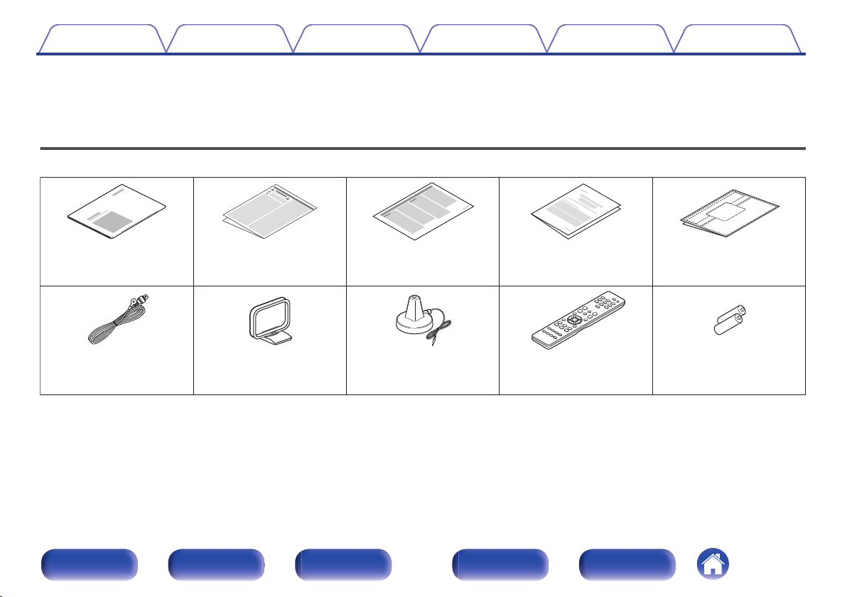
Cable labelsNotes on radioSafety InstructionsQuick Start Guide
Sound calibration
microphone
AM loop antennaFM indoor antenna
R03/AAA batteries
Remote control unit
(RC-1254)
Warranty
(for North America
model only)
Contents Connections Playback Settings Tips Appendix
Thank you for purchasing this Denon product.
To ensure proper operation, please read this owner’s manual carefully before using the product.
After reading this manual, be sure to keep it for future reference.
Accessories
Check that the following parts are supplied with the product.
Front panel Display Rear panel Remote Index
6
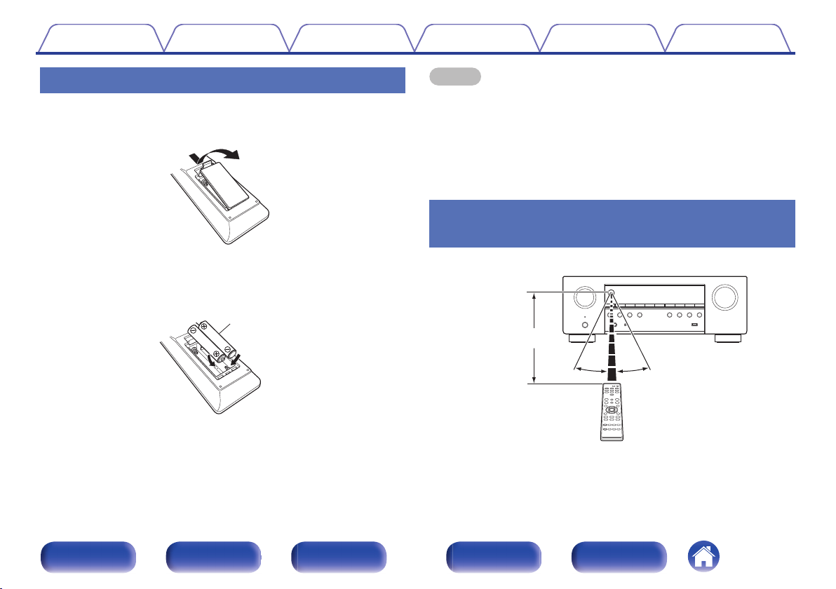
Batteries
Approx. 23 ft/7 m
30°
30°
Contents
Connections Playback Settings Tips Appendix
Inserting the batteries
Remove the rear lid in the direction of the arrow and
1
remove it.
Insert two batteries correctly into the battery
2
compartment as indicated.
Put the rear cover back on.
3
NOTE
To prevent damage or leakage of battery fluid:
0
Do not use a new battery together with an old one.
0
Do not use two different types of batteries.
0
Remove the batteries from the remote control unit if it will not be in use for long
0
periods.
If the battery fluid should leak, carefully wipe the fluid off the inside of the battery
0
compartment and insert new batteries.
Operating range of the remote control unit
Point the remote control unit at the remote sensor when operating it.
Front panel Display Rear panel Remote Index
7
8K,
4K 120Hz
8K,
4K 120Hz
Contents
Features
Connections Playback Settings Tips Appendix
High quality sound
With discrete circuit technology, the power amplifier provides
0
identical quality for all 5-channels (90 Watts x 5-channels)
For optimum realism and stunning dynamic range, the power amplifier
section features discrete power devices (not integrated circuitry).
By using high current, high power discrete power devices, the amplifier
is able to easily drive high quality speakers.
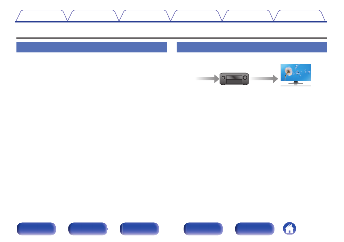
High performance
8K 60Hz input/output supported
0
When 8K Ultra HD (High Definition) is used, an input/output speed of 60
frames per second (60p) is achieved for video signals. When connected
to 8K Ultra HD and 60p video signal input compatible TV, you can enjoy
the sense of realism only available from high-definition images, even
when viewing fast-moving video.
This unit supports a wide range of HDR content, delivering even higher
definition video.
HDCP 2.3
0
This unit is compatible with HDCP 2.3 copyright protection standard.
Front panel Display Rear panel Remote Index
8
8K Ultra HD
8K 8K
1080p/4K 60Hz
8K
up scaling
41
OutIn
Contents
Connections Playback Settings Tips Appendix
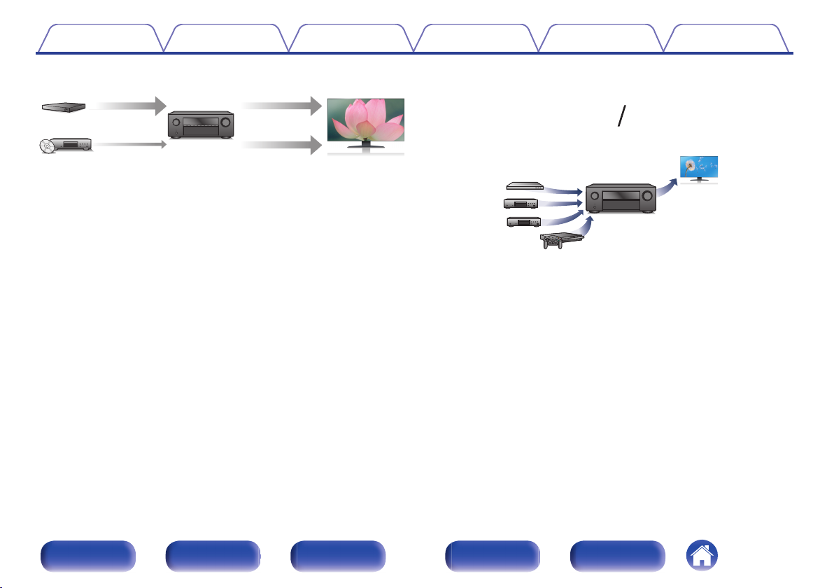
Digital video processor upscales 1080p / 4K to 8K
0
This unit is equipped with a 8K video upscaling function that allows
1080p/4K video to be output via HDMI at 8K (7680 × 4320 pixels)
resolution. This function enables the device to be connected to a TV
using a single HDMI cable, and produces high definition images for any
video source.
eARC (Enhanced Audio Return Channel) function compatibility
0
The eARC function is compatible with conventional ARC functioncompatible audio formats in addition to multichannel linear PCM, Dolby
TrueHD, DTS-HD and other audio formats a conventional ARC function
cannot transmit.
Additionally, connecting to an eARC function-compatible television
enables enjoyment of higher-quality surround playback of the audio
content played from your television.
HDMI connections enable connection to various digital AV
0
devices (4 inputs, 1 output)
This unit is equipped with 4 HDMI inputs and 1 HDMI output enabling
connection to various HDMI compatible devices such as Blu-ray Disc
players, game consoles and HD video camcorders.
Front panel Display Rear panel Remote Index
9
Contents
Wireless connection with Bluetooth devices can be carried out
0
easily (v p. 44)
You can enjoy music simply by connecting wirelessly with your
smartphone, tablet, PC, etc.
Energy-saving design
0
This unit is equipped with an ECO Mode function that allows you to
enjoy music and movies while reducing the power consumption during
use, and also an auto-standby function that automatically turns off the
power supply when the unit is not in use. This helps reduce
unnecessary power use.
Connections Playback Settings Tips Appendix
Easy operation
“Setup Assistant” provides easy-to-follow setup instructions
0
First select the language when prompted. Then simply follow the
instructions displayed on the TV screen to set up the speakers etc.
Easy to use Graphical User Interface
0
This unit is equipped with a Graphical User Interface for improved
operability.
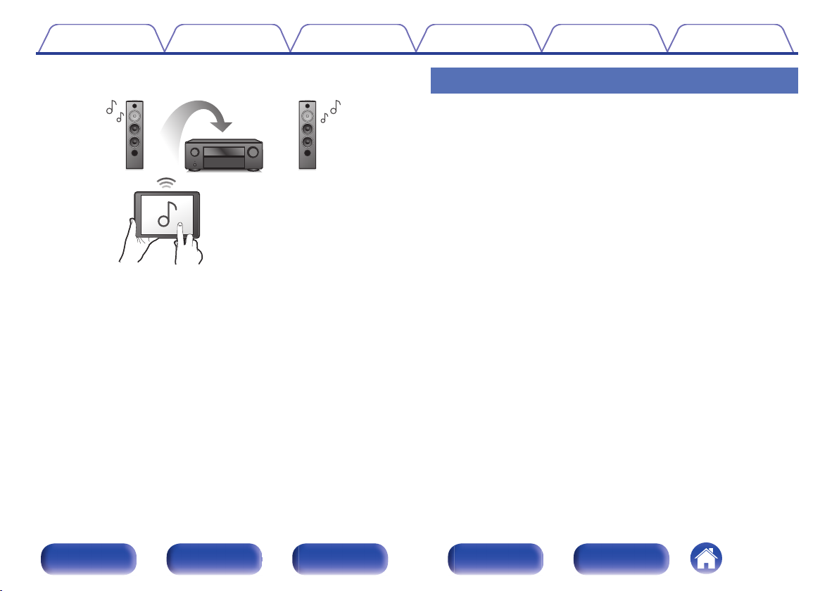
Compatible with the “Denon 500 Series Remote” app performing
0
basic operations of the unit with an iPad, iPhone or Android™
devices (Google, Amazon Kindle Fire)
The “Denon 500 Series Remote”z application allows you to wireless
control this unit from an iPhone, iPad, Android smartphone or tablet
when paired and connected via Bluetooth. Basic functions include:
Power ON/OFF, volume, mute, and source selection.
Download the appropriate “Denon 500 Series Remote” for your iOS or Android
z
devices. In order to use “Denon 500 Series Remote”, your iOS or Android device
needs to be paired with this unit in advance.
Front panel Display Rear panel Remote Index
10
re
Q2Q1Q0uQ3oi
tqw y
Q
9
Q
6
Q7Q
8
W
0
Q
5
Q
4
Contents
Connections Playback Settings Tips Appendix
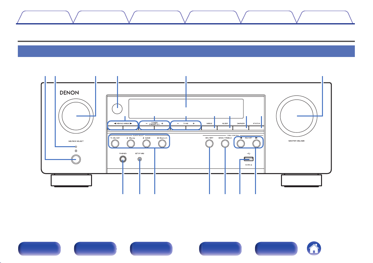
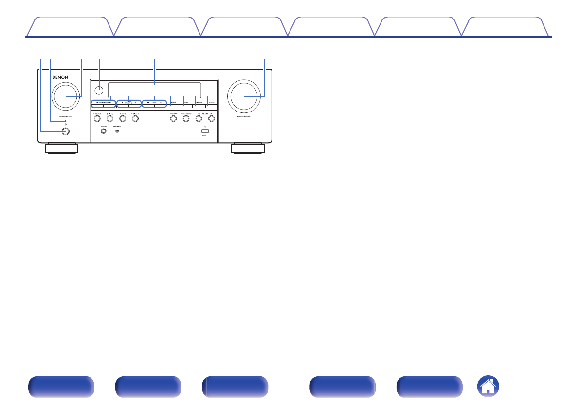
Part names and functions
Front panel
For details, see the next page.
Front panel Display Rear panel Remote Index
11
retqw y
Q2Q1Q0 Q3oiu
Contents
Power operation button (X)
A
Used to turn the power on/off (standby). (v p. 40)
Power indicator
B
This is lit as follows according to the power status:
Green: Power on
0
Off: Normal standby
0
Red:
0
When “HDMI Pass Through” is set to “On” (v p. 81)
0
0
When “HDMI Control” is set to “On” (v p. 81)
When “Bluetooth Standby” is set to “On” (v p. 100)
0
SOURCE SELECT knob
C
This selects the input source. (v p. 40)
Connections Playback Settings Tips Appendix
Remote control sensor
D
This receives signals from the remote control unit. (v p. 7)
Display
E
This displays various pieces of information. (v p. 14)
MASTER VOLUME knob
F
This adjusts the volume level. (v p. 41)
SOUND MODE buttons (0 1)
G
These select the sound mode. (v p. 60)
Tuner preset channel buttons
H
(TUNER PRESET CH +, –)
These select preset broadcast stations. (v p. 52)
Tuning buttons (TUNE +, –)
I
Select either FM broadcast or AM broadcast. (v p. 50)
Tuning mode select button (MODE)
J
This switches the tuning mode. (v p. 50)
SLEEP button
K
This sets the sleep timer. (v p. 66)
DIMMER button
L
Each press of this switches the brightness of the display. (v p. 102)
STATUS button
M
Each press of this switches the status information that is shown on the
display.
Front panel Display Rear panel Remote Index
12
Q
9
Q
6
Q7Q8W
0
Q
5Q4
Contents Connections Playback Settings Tips Appendix
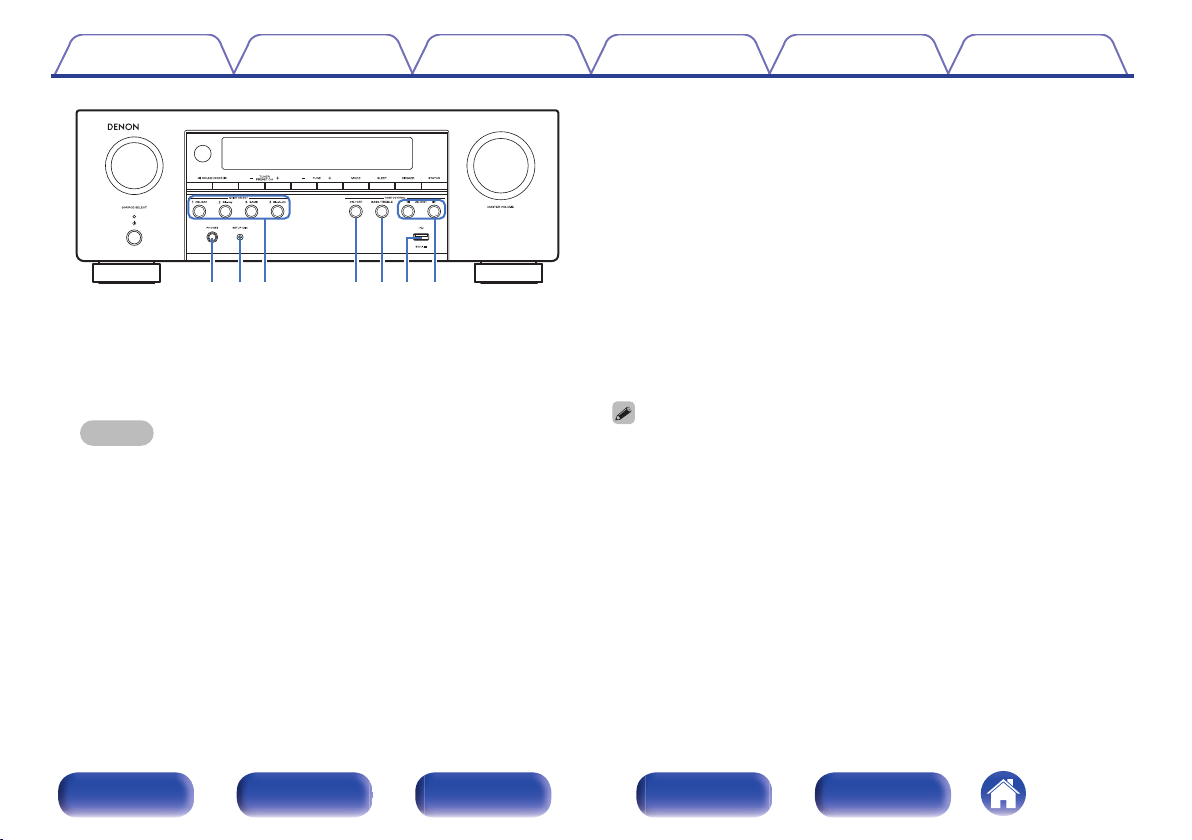
QUICK SELECT buttons
P
With a single press of any of these buttons, you can call up various
settings you’ve registered to each button such as the input source,
volume level and sound mode settings. (v p. 68)
TONE CONTROL ON/OFF button
Q
Set the tone control function to on/off. (v p. 57)
BASS/TREBLE button
R
Selects the range for which to adjust the tone. (v p. 57)
S
USB port (T)
Headphones jack (PHONES)
N
This is used to connect headphones.
When the headphones are plugged into this jack, audio will no longer
be output from the connected speakers or from the SUBWOOFER
connectors.
This is used to connect USB storages (such as USB memory devices)
and the USB cable supplied. (v p. 35)
Tone adjustment buttons (ADJUST 0 1)
T
Adjusts the tonal quality of the sound. (v p. 57)
NOTE
To prevent hearing loss, do not raise the volume level excessively when using
0
headphones.
SETUP MIC jack
O
This is used to connect the supplied Sound calibration microphone.
(v p. 92)
Front panel Display Rear panel Remote Index
BASS/TREBLE button and ADJUST 0 1 buttons can be operated when the
0
“Tone” setting is “On”. (v p. 57)
13
tyreqw
ui
Contents Connections Playback Settings Tips Appendix
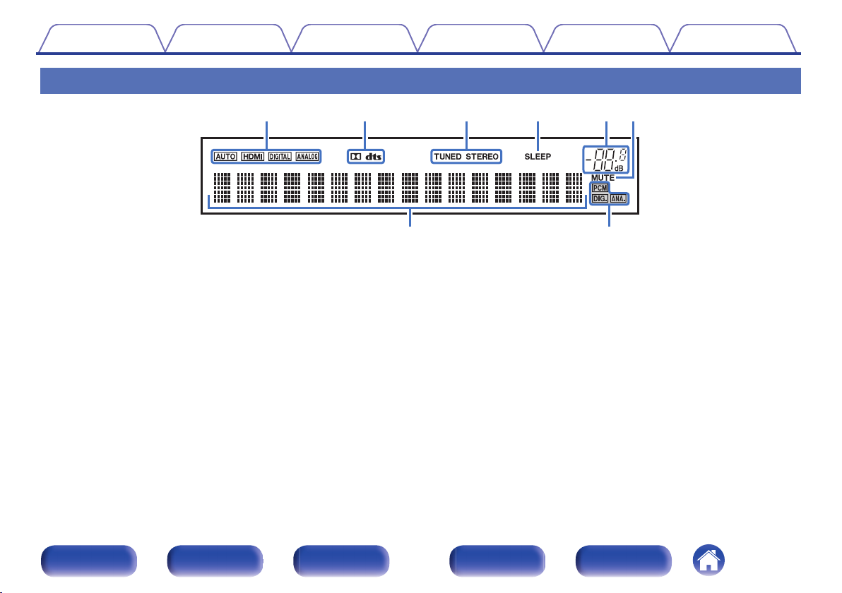
Display
Input mode indicators
A
These light according to the audio input mode settings of each input
source. (v p. 88)
Decoder indicators
B
These light when Dolby or DTS signals are input or when the Dolby or
DTS decoder is running.
Tuner reception mode indicators
C
These light up according to the reception conditions when the input
source is set to “Tuner”.
TUNED: Lights up when the broadcast is properly tuned in.
STEREO: Lights up when receiving FM stereo broadcasts.
Sleep timer indicator
D
This lights when the sleep mode is selected. (v p. 66)
Volume indicator
E
MUTE indicator
F
This blinks while the sound is muted. (v p. 41)
Information display
G
The input source name, sound mode, setting values and other
information are displayed here.
Input signal indicators
H
The respective indicator will light corresponding to the input signal.
(v p. 88)
Front panel Display Rear panel Remote Index
14
t
rewq
uy
Contents
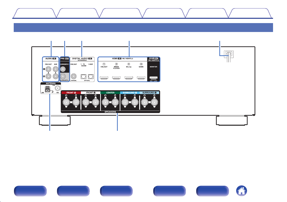
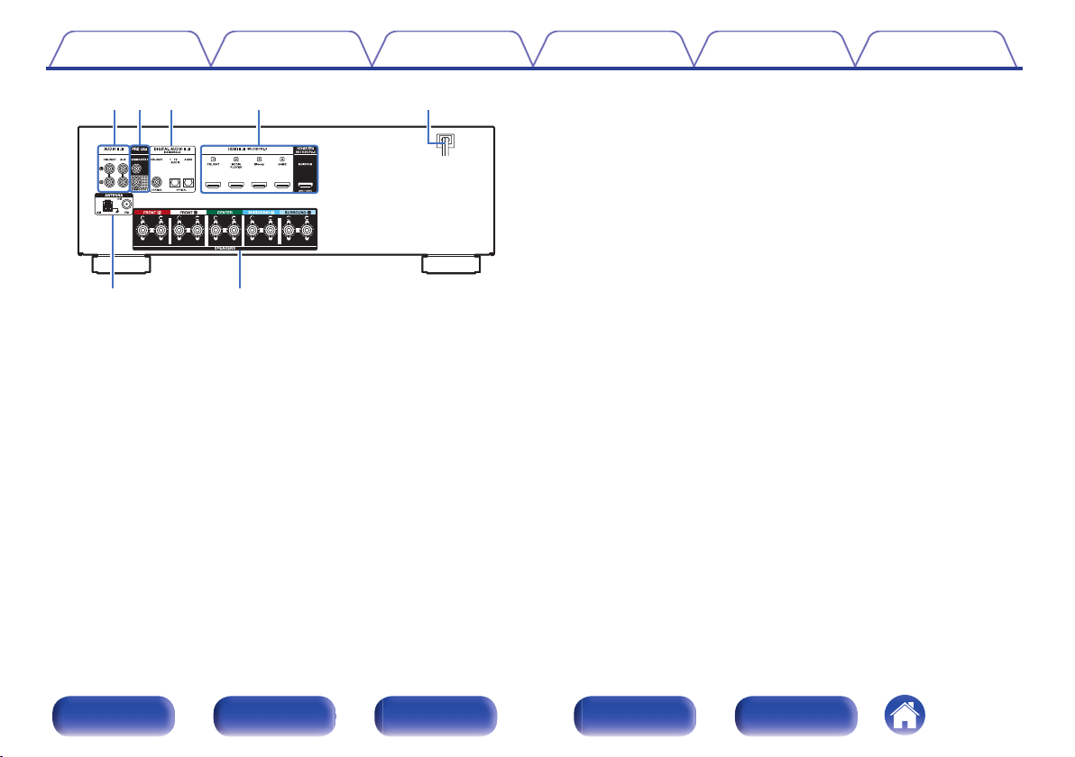
Rear panel
Connections Playback Settings Tips Appendix
For details, see the next page.
Front panel Display Rear panel Remote Index
15
t
rw eq
uy
Contents
Analog audio connectors (AUDIO)
A
Used to connect devices equipped with analog audio connectors.
(v p. 31)
PRE OUT connectors
B
Used to connect a subwoofer with a built-in amplifier. (v p. 24)
Digital audio connectors (DIGITAL AUDIO)
C
Used to connect devices equipped with digital audio connectors.
“Connection 2 : TV equipped with an HDMI connector and
0
incompatible with the ARC / eARC” (v p. 29)
“Connecting a set-top box (Satellite tuner/cable TV)” (v p. 31)
0
Connections Playback Settings Tips Appendix
HDMI connectors
D
Used to connect devices equipped with HDMI connectors.
“Connection 1 : TV equipped with an HDMI connector and
0
compatible with the ARC / eARC” (v p. 28)
“Connection 2 : TV equipped with an HDMI connector and
0
incompatible with the ARC / eARC” (v p. 29)
“Connecting a set-top box (Satellite tuner/cable TV)” (v p. 31)
0
“Connecting a Blu-ray Disc player or DVD player” (v p. 33)
0
“Connecting a game console” (v p. 34)
0
Power cord (v p. 38)
E
FM/AM antenna terminals (ANTENNA)
F
Used to connect FM antennas and AM loop antennas. (v p. 36)
Speaker terminals (SPEAKERS)
G
Used to connect speakers. (v p. 23)
Front panel Display Rear panel Remote Index
16
w
r
e
t
q
Contents Connections Playback Settings Tips Appendix
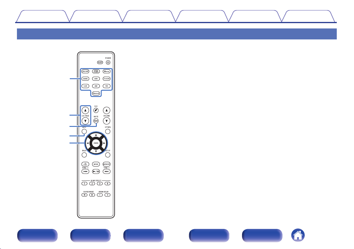
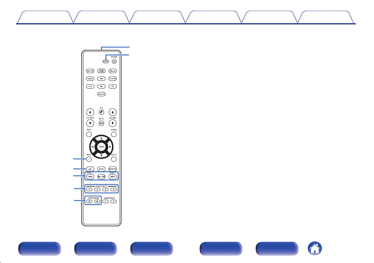
Remote control unit
Input source select buttons
A
These select the input source. (v p. 40)
Channel/page search buttons (CH/PAGE df)
B
These select radio stations registered to presets or switch pages.
(v p. 52)
MUTE button (:)
C
This mutes the output audio. (v p. 41)
Information button (INFO)
D
This displays the status information on the TV screen. (v p. 104)
Cursor buttons (uio p)
E
These select items.
Front panel Display Rear panel Remote Index
17
Q2
Q1
Q0
o
i
u
y
Contents
Connections Playback Settings Tips Appendix
BACK button
F
This returns to the previous screen.
Channel level button (CH LEVEL)
G
Adjusting the volume of the speakers. (v p. 65)
System buttons
H
These perform playback related operations.
Tuning up / Tuning down buttons (TUNE +, –)
These select either FM broadcast or AM broadcast. (v p. 50)
QUICK SELECT buttons (1 – 4)
I
These call up settings registered to each button, such as input source,
volume level and sound mode settings. (v p. 68)
SOUND MODE buttons (0 1)
J
These select the sound mode. (v p. 60)
Remote control signal transmitter
K
This transmits signals from the remote control unit. (v p. 7)
SLEEP button
L
This sets the sleep timer. (v p. 66)
Front panel Display Rear panel Remote Index
18
Q3
Q5
Q4
Q8
Q9
W0
Q6
Q7
W1
Contents
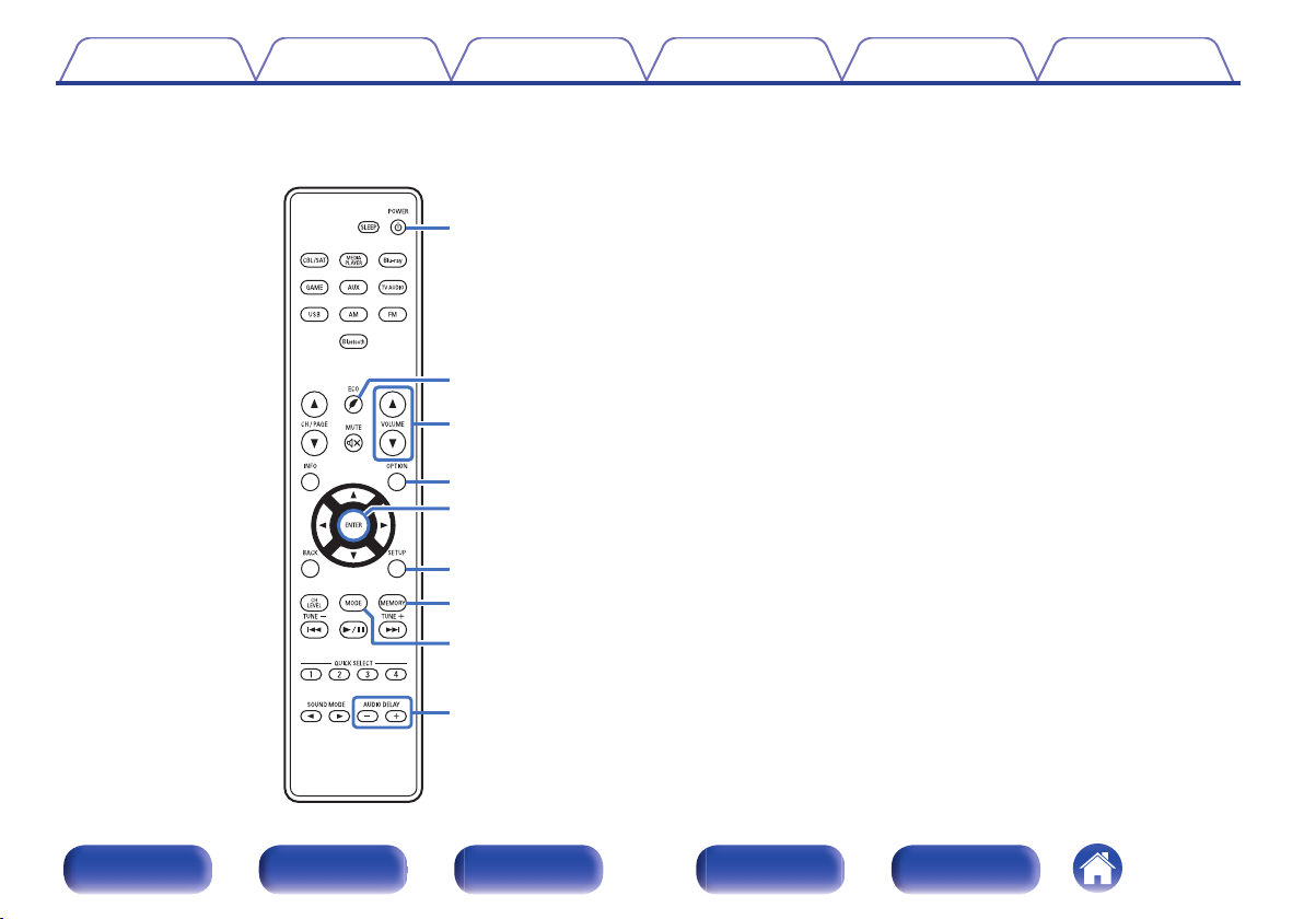
Connections Playback Settings Tips Appendix
POWER button (X)
M
This turns the power on/off. (v p. 40)
N
ECO Mode button (G)
This switches to ECO Mode. (v p. 98)
VOLUME buttons (df)
O
These adjust the volume level. (v p. 41)
OPTION button
P
This displays the option menu on the TV screen.
ENTER button
Q
This determines the selection.
SETUP button
R
This displays the menu on the TV screen. (v p. 73)
Preset memory button (MEMORY)
S
The current broadcast station that is preset. (v p. 52)
Tuning mode select button (MODE)
T
This switches the tune mode. (v p. 50)
AUDIO DELAY buttons (+, –)
U
Compensates for incorrect timing between video and audio. (v p. 58)
Front panel Display Rear panel Remote Index
19
R
L
R
L
Contents Connections Playback Settings Tips Appendix
o
Contents
Speaker installation 21
Connecting speakers 23
Connecting a TV 27
Connecting a playback device 30
Connecting a USB memory device to the USB port 35
Connecting an FM/AM antenna 36
Connecting the power cord 38
NOTE
Do not plug in the power cord until all connections have been completed.
0
However, when the “Setup Assistant”is running, follow the instructions in the
“Setup Assistant” (page 7 in the separate “Quick Start Guide”) screen for making
connections. (During “Setup Assistant” operation, the input/output connectors do
not conduct current.)
Do not bundle power cords together with connection cables. Doing so can result in
0
noise.
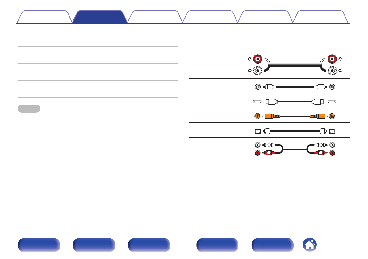
o
Cables used for connections
Provide necessary cables according to the devices you want to
connect.
Speaker cable
Subwoofer cable
HDMI cable
Coaxial digital cable
Optical cable
Audio cable
Front panel Display Rear panel Remote Index
20
FL
SW1
C
SL
FR
SR
SW2
Contents Connections Playback Settings Tips Appendix
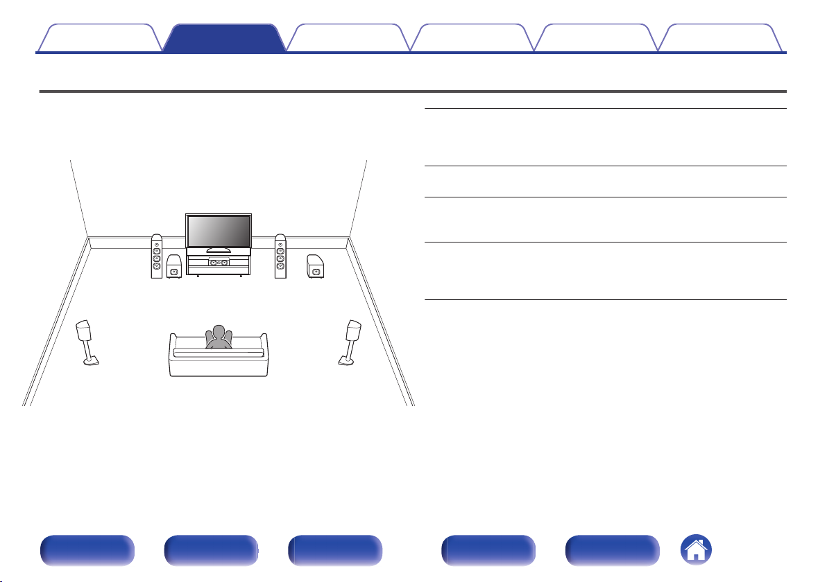
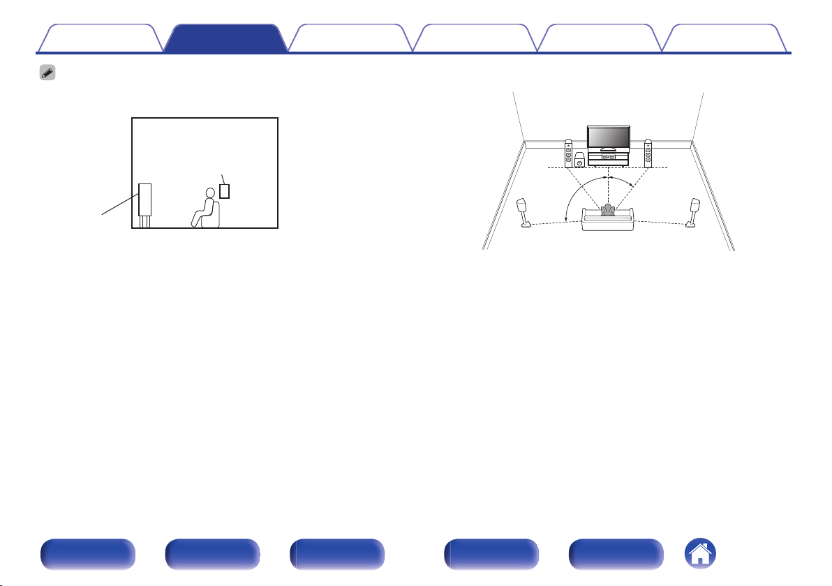
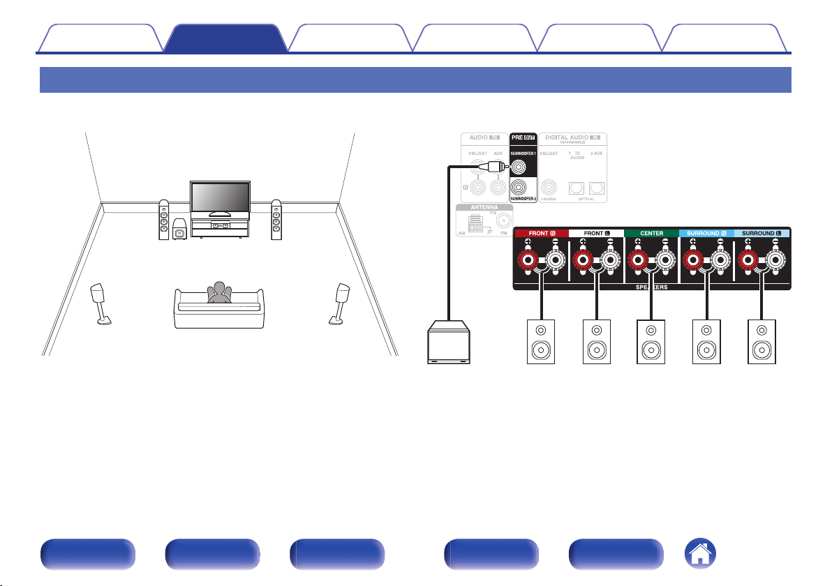
Speaker installation
Determine the speaker system depending on the number of speakers you
are using and install each speaker and subwoofer in the room.
Speaker installation is explained using this example of a typical
installation.
FL/FR
(Front speaker left/
right):
C
(Center speaker):
SL/SR
(Surround speaker left/
right):
SW 1/2
(Subwoofer) :
Place the FRONT left and right speakers an
equal distance from the main listening position.
The distance between each speaker and your TV
should also be the same.
Place the CENTER speaker in between the front
speakers and above or below your TV.
Place the SURROUND left and right speakers an
equal distance to the left and right sides of the
main listening position.
Place the SUBWOOFER at a convenient location
near the front speakers. If you have two
subwoofers, place them asymmetrically across
the front of your room.
Front panel Display Rear panel Remote Index
21
GViewed from the sideH
Surround
speaker
Front speaker
z1
z2
FL
SW
C
SL
FR
SR
Contents
Use the illustration below as a guide for how high each speaker should be
0
installed. The height does not need to be exactly the same.
Connections Playback Settings Tips Appendix
When 5.1-channel speakers are installed
o
z
1 22° - 30° z2 120°
Front panel Display Rear panel Remote Index
22
Contents Connections Playback Settings Tips Appendix
Connecting speakers
Here we connect the speakers in the room to this unit.
Before connecting speakers
Peel off about 3/8 inch (10 mm) of sheathing from the
NOTE
Disconnect this unit’s power plug from the power outlet before connecting the
0
speakers. Also, turn off the subwoofer.
Connect so that the speaker cable core wires do not protrude from the speaker
0
terminal. The protection circuit may be activated if the core wires touch the rear
panel or if the + and - sides touch each other. (“Protection circuit” (v p. 138))
Never touch the speaker terminals while the power cord is connected. Doing so
0
could result in electric shock. When the “Setup Assistant” (page 7 in the separate
“Quick Start Guide”) is running, follow the instructions in the “Setup Assistant”
screen for making connections. (Power is not supplied to the speaker terminals
while the “Setup Assistant” is running.)
Use speakers with an impedance of 6 – 16 Ω/ohms.
0
o
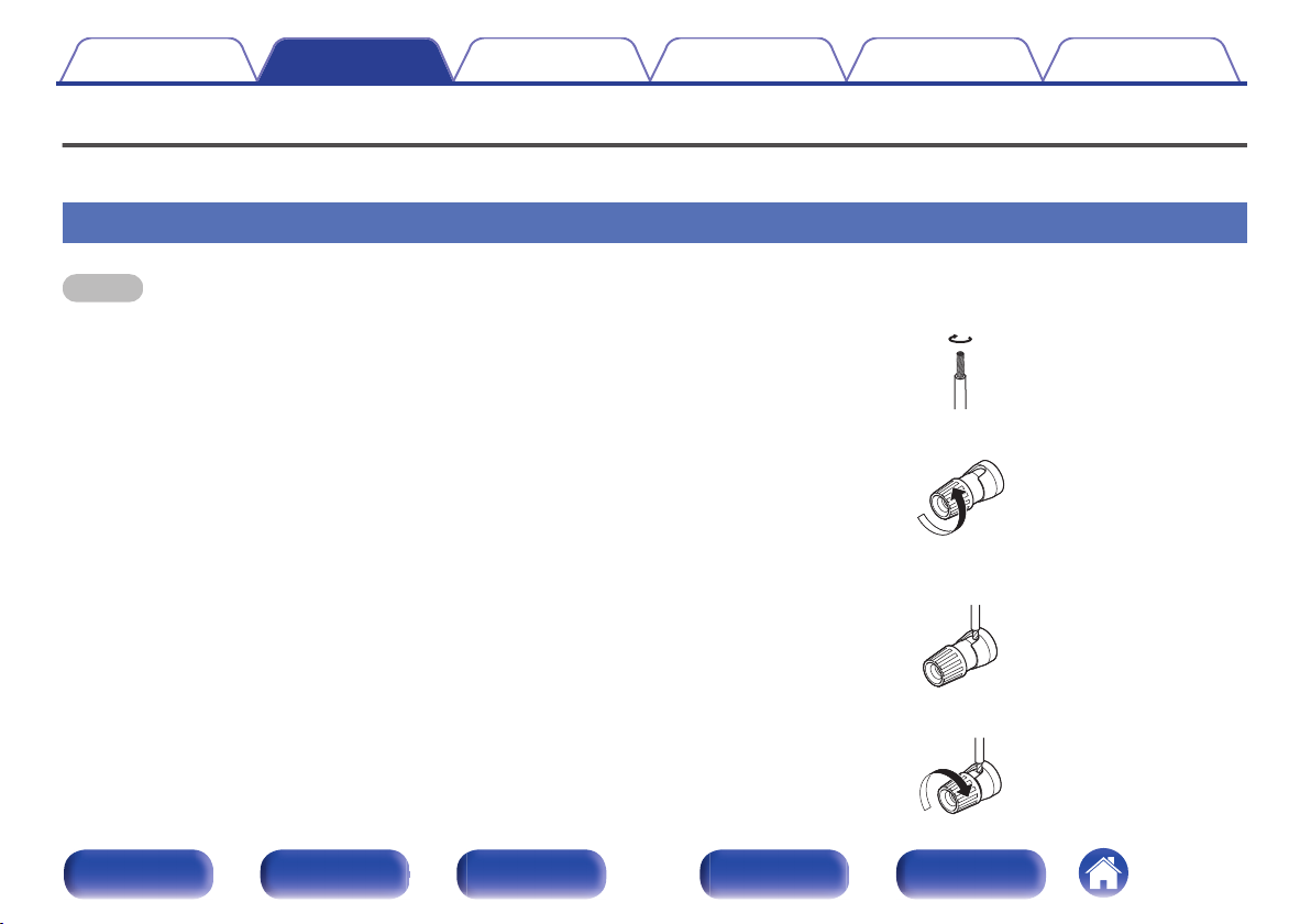
Connecting the speaker cables
Carefully check the left (L) and right (R) channels and + (red) and –
(black) polarities on the speakers being connected to this unit, and be
sure to connect the channels and polarities correctly.
1
tip of the speaker cable, then either twist the core wire
tightly or terminate it.
Turn the speaker terminal counterclockwise to loosen it.
2
Insert the speaker cable’s core wire to the hilt into the
3
speaker terminal.
Turn the speaker terminal clockwise to tighten it.
4
Front panel Display Rear panel Remote Index
23
SW1 SW2
Contents Connections Playback Settings Tips Appendix
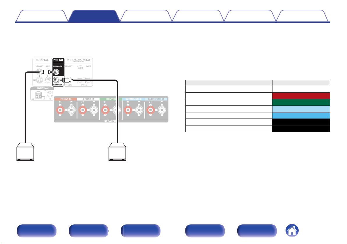
o
Connecting the subwoofer
Use a subwoofer cable to connect the subwoofer. Two subwoofers can
be connected to this unit.
The same signal is output from the respective subwoofer terminals.
o
About the cable labels (supplied) for channel
identification
The channel display section for speaker terminals on the rear panel is
color-coded for each channel to be identifiable.
Attach the cable label corresponding to each speaker to each speaker
cable.
This makes it easy to connect the correct cable to the speaker
terminals on the rear panel.
Speaker Color
FRONT L White
FRONT R Red
CENTER Green
SURROUND L Light blue
SURROUND R Blue
SUBWOOFER 1 Black
SUBWOOFER 2 Black
Front panel Display Rear panel Remote Index
24
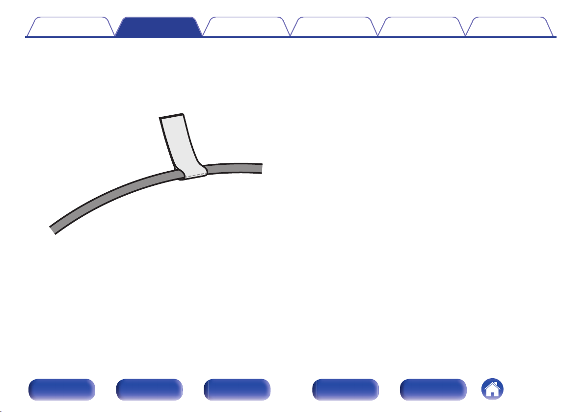
Contents
The supplied cable labels include labels for the speaker and HDMI
cables. Attach a cable label to each cable that matches the speakers
and HDMI devices being connected, as shown below. This makes it
easy to identify and properly connect the cables between your
components.
G How to attach the cable labels H
Connections Playback Settings Tips Appendix
Front panel Display Rear panel Remote Index
25
FL
SW C
SL
FR
SR
SW
SLFLFR C SR
Contents Connections Playback Settings Tips Appendix
Standard connection
This serves as a basic 5.1-channel surround system.
Sound modes such as Dolby Pro Logic g are supported.
Front panel Display Rear panel Remote Index
26
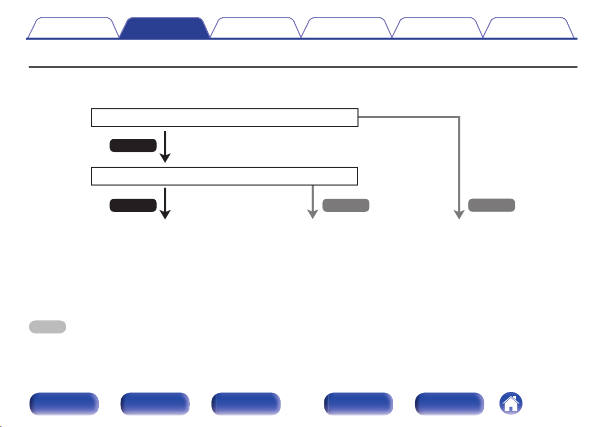
No
Yes
Is the TV equipped with an HDMI connector?
Yes No
Is the TV compatible with the ARC / eARC?
z
Contents Connections Playback Settings Tips Appendix
Connecting a TV
Connect a TV to this unit so that the input video is output to the TV. You can also enjoy audio from the TV on this unit.
How to connect a TV depends on the connectors and functions equipped on the TV.
“Connection 1 : TV equipped with an HDMI
connector and compatible with the ARC /
eARC” (v p. 28)
What is ARC and eARC?
z
ARC (Audio Return Channel) sends audio back to this unit using the same HDMI cable that sends video from this unit to your TV.
This allows this unit to process the sound from your TV’s built-in tuner and apps.
TVs with eARC(Enhanced Audio Return Channel) port will provide additional support for high bitrate multichannel audio (Dolby TrueHD and DTS-HD).
Please refer to your TV Owner’s Manual for details about eARC support for your particular model.
NOTE
Use a TV with a 2 prong power plug for this unit. Do not connect a TV with a 3 prong power plug, as this may cause noise.
0
“Connection 2 : TV equipped with an HDMI
connector and incompatible with the ARC /
eARC” (v p. 29)
You cannot connect the TV to this
unit.
Front panel Display Rear panel Remote Index
27
(ARC / eARC)
IN
HDMI
TV
Contents
Connections Playback Settings Tips Appendix
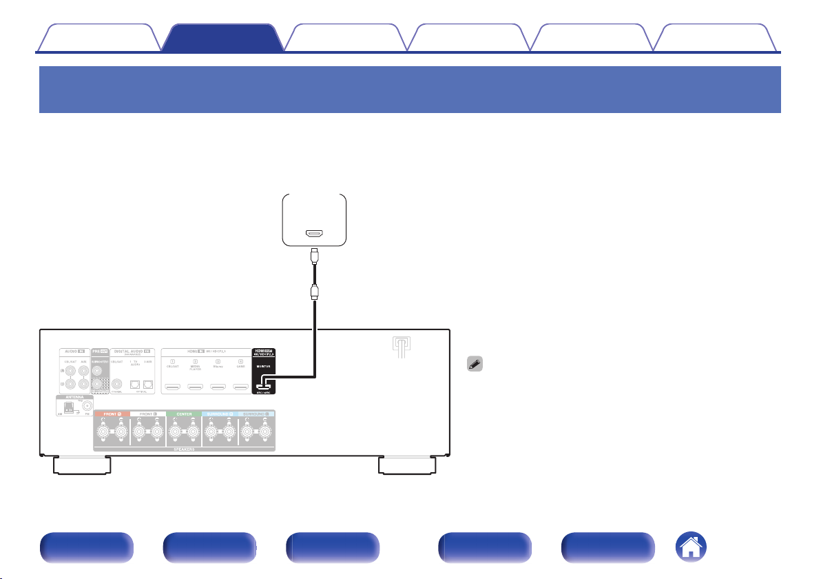
Connection 1 : TV equipped with an HDMI connector and compatible with the ARC / eARC
Using a high quality HDMI cablez, connect one end to the HDMI port labeled “eARC” or “ARC” on your TV. Connect the other end to the HDMI OUT
MONITOR port on this unit.
When a TV with eARC support is connected, the eARC function of this unit is enabled automatically and the television audio is played back. When a TV
with ARC support is connected, set “ARC” in the menu to “On”. (v p. 82)
For 4K TVs we recommend using an HDMI cable labeled “High Speed”
z
and “with Ethernet” .
For 8K TVs we recommend using an HDMI cable labeled “Ultra High
z
Speed”.
eARC function settings may be required depending on the eARC
0
function-compatible television you are using. Make sure eARC is set to
on if this setting exists on your television. For more information, check
your television’s owner’s manual.
Set “4K/8K Signal Format” to “8K Enhanced”: in the menu to enjoy 8K
0
video. (v p. 84)
Front panel Display Rear panel Remote Index
28
OUT
OPTICAL
OUT IN
IN
HDMI
TV
Contents Connections Playback Settings Tips Appendix
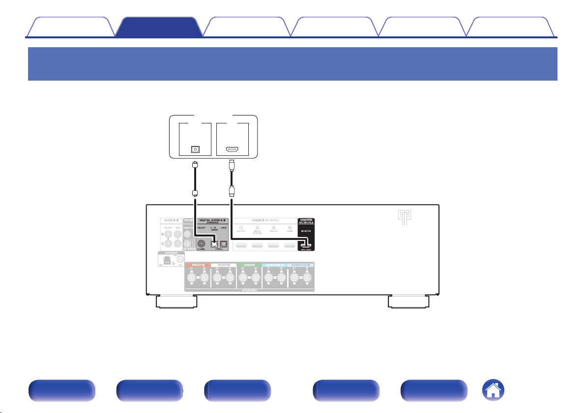
Connection 2 : TV equipped with an HDMI connector and incompatible with the ARC / eARC
Use an HDMI cable to connect the TV to this unit.
To listen to audio from TV on this unit, use an optical cable to connect the TV to this unit.
Front panel Display Rear panel Remote Index
29
Contents Connections Playback Settings Tips Appendix
Connecting a playback device
This unit is equipped with HDMI video input connectors and three types of audio input connectors (HDMI, digital audio and audio).
Select input connectors on this unit according to the connectors equipped on the device you want to connect.
If the device connected to this unit is equipped with an HDMI connector, it is recommended to use HDMI connections.
In the HDMI connection, audio and video signals can be transmitted through a single HDMI cable.
“Connecting a set-top box (Satellite tuner/cable TV)” (v p. 31)
0
“Connecting a Blu-ray Disc player or DVD player” (v p. 33)
0
“Connecting a game console” (v p. 34)
0
Connect devices to this unit as indicated by the input sources printed on the audio/video input connectors of this unit.
0
The source that is assigned to the OPTICAL 1, OPTICAL 2 and COAXIAL connectors can be changed. See “Input Assign” on how to change the input source assigned to the
0
input connectors. (v p. 87)
To play back audio signals that are input to this unit on a TV connected via HDMI, set “HDMI Audio Out” to “TV”. (v p. 80)
0
To enjoy content that is copyright protected by HDCP 2.2 or HDCP 2.3, use a playback device and TV compatible with HDCP 2.2 or HDCP 2.3.
0
Front panel Display Rear panel Remote Index
30

R
L
R
L
OUT
HDMI
OUT
COAXIAL
AUDIO
AUDIO
RL
OUT
or
Satellite tuner /
Cable TV
Satellite tuner /
Cable TV
(HDMI incompatible device)
Contents Connections Playback Settings Tips Appendix
Connecting a set-top box (Satellite tuner/cable TV)
This explanation uses the connection with a satellite tuner/cable TV STB as an example.
Select the input connectors on this unit to match the connectors on the device that you want to connect to.
Front panel Display Rear panel Remote Index
31

OUT
HDMI
Media player
Contents Connections Playback Settings Tips Appendix
Connecting a media player
This explanation uses the connection with a media player as an example.
Front panel Display Rear panel Remote Index
32

OUT
HDMI
Blu-ray Disc player /
DVD player
Contents Connections Playback Settings Tips Appendix
Connecting a Blu-ray Disc player or DVD player
This explanation uses the connection with a Blu-ray Disc player or DVD player as an example.
Front panel Display Rear panel Remote Index
33

OUT
HDMI
Game console
Contents Connections Playback Settings Tips Appendix
Connecting a game console
This explanation uses the connection with a game console as an example.
Front panel Display Rear panel Remote Index
34

MASTER VOLUME
USB memory
device
Contents Connections Playback Settings Tips Appendix
Connecting a USB memory device to the USB port
For operating instructions see “Playing a USB memory device” (v p. 42).
Denon does not guarantee that all USB memory devices will operate or receive power. When using a portable USB hard disk drive (HDD) which came with an AC adapter,
0
use that device’s supplied AC adapter.
NOTE
USB memory devices will not work via a USB hub.
0
It is not possible to use this unit by connecting the unit’s USB port to a PC via a USB cable.
0
Do not use an extension cable when connecting a USB memory device. This may cause radio interference with other devices.
0
Front panel Display Rear panel Remote Index
35

wqe
Black
AM loop antenna
(supplied)
FM indoor antenna
(supplied)
White
Contents Connections Playback Settings Tips Appendix
Connecting an FM/AM antenna
Connect the antenna, tune in to a broadcast and then move the antenna to
the location where there is least noise. Then use tape, etc. to fix the
antenna in this location. (“Listening to FM/AM broadcasts” (v p. 49))
If you are unable to receive a good broadcast signal, we recommend installing an
0
outdoor antenna. For details, inquire at the retail store where you purchased the
unit.
NOTE
Make sure the AM loop antenna lead terminals do not touch metal parts of the
0
panel.
Front panel Display Rear panel Remote Index
36
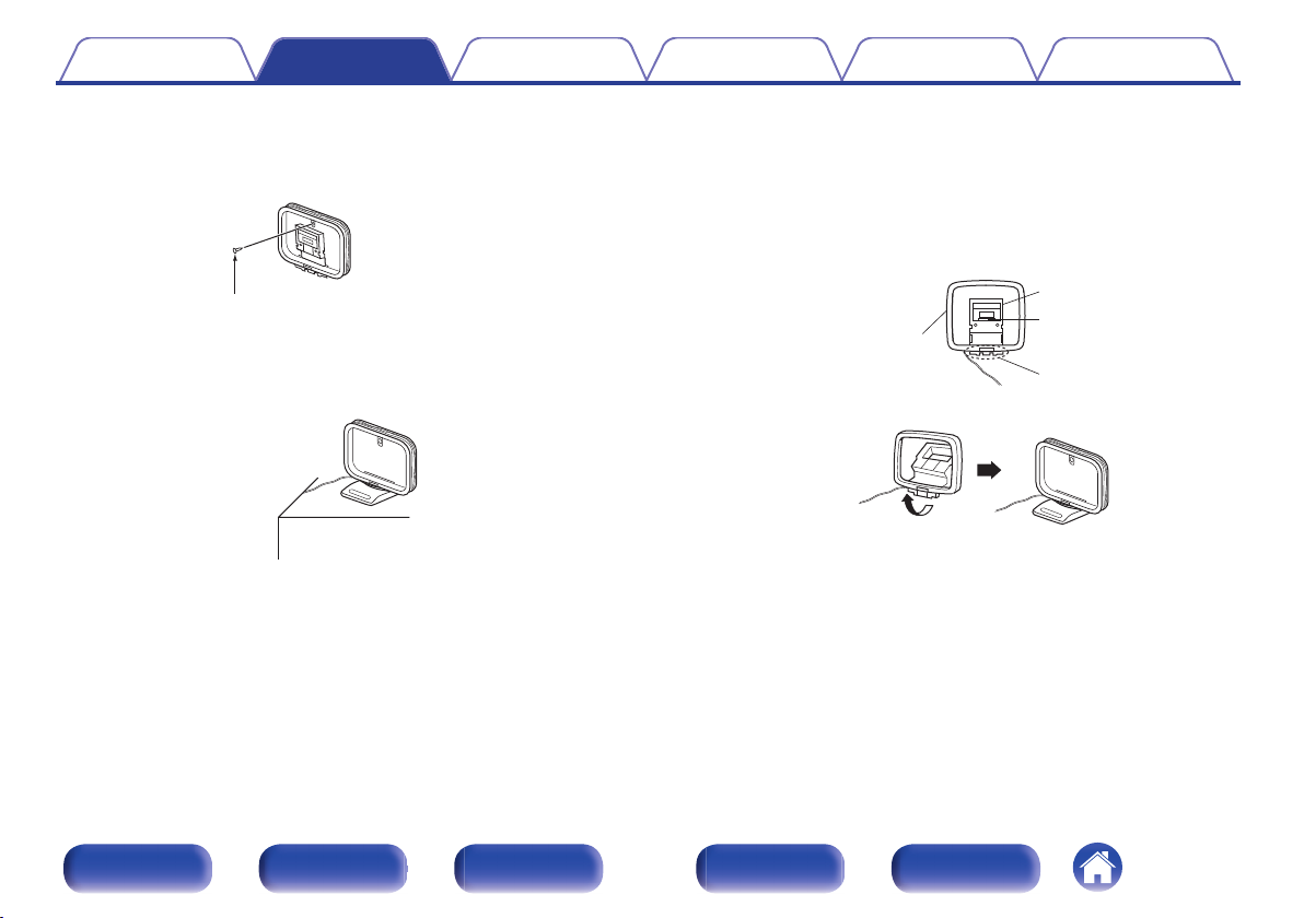
Nail, tack, etc.
Projecting part
Square hole
Stand
Loop antenna
Contents Connections Playback Settings Tips Appendix
o
Using the AM loop antenna
Suspending on a wall
Suspend directly on a wall without assembling.
Standing alone
Use the procedure shown above to assemble.
When assembling, refer to “AM loop antenna assembly”.
o
AM loop antenna assembly
Put the stand section through the bottom of the loop
1
antenna from the rear and bend it forward.
Insert the projecting part into the square hole in the
2
stand.
Front panel Display Rear panel Remote Index
37

(AC 120 V, 60 Hz)
To household power outlet
Power cord
Contents Connections Playback Settings Tips Appendix
Connecting the power cord
After completing all the connections, insert the power plug into the power outlet.
Front panel Display Rear panel Remote Index
38

Contents Connections Playback Settings Tips Appendix
o
Contents
Basic operation
Turning the power on 40
Selecting the input source 40
Adjusting the volume 41
Turning off the sound temporarily (Muting) 41
Selecting a sound mode 60
Convenience functions
Compatible with the “Denon 500 Series Remote” app 54
Convenience functions 55
HDMI control function 64
Adjusting the volume of each channel to match the input source
(Channel Level Adjust) 65
Sleep timer function 66
Quick select plus function 68
Playback a device
Playing a DVD player/Blu-ray Disc player 41
Playing a USB memory device 42
Listening to music on a Bluetooth device 44
Listening to FM/AM broadcasts 49
Front panel Display Rear panel Remote Index
39

MUTE
POWER
VOLUME
df
X
:
Input source
select
buttons
Contents Connections Playback Settings Tips Appendix
Basic operation
Turning the power on
Press POWER X to turn on power to the unit.
1
You can press the input source select button when the unit is in standby mode to
0
turn on the power.
You can also switch the power to standby by pressing X on the main unit.
0
Selecting the input source
Front panel Display Rear panel Remote Index
40
Press the input source select button to be played back.
1
The desired input source can be selected directly.
You can also select the input source by turning SOURCE SELECT on the main
0
unit.

Contents Connections Playback Settings Tips Appendix
Adjusting the volume
Use VOLUME df to adjust the volume.
1
The variable range differs according to the input signal and channel level setting.
0
You can also adjust the master volume by turning MASTER VOLUME on the main
0
unit.
Turning off the sound temporarily (Muting)
Press MUTE :.
1
“MUTE” appears on the display.
0
0
appears on the TV screen.
The sound is reduced to the level set at “Mute Level” in the menu. (v p. 79)
0
To cancel mute, either adjust the sound volume or press MUTE : again.
0
0
is displayed on the TV screen for more than 5 minutes when the “Screen
If
Saver” is set to “On”, the symbol moves randomly over the TV screen.
(v p. 84)
Playback a Blu-ray Disc player/DVD player
The following describes the procedure for playing Blu-ray Disc player/DVD
player.
Prepare for playback.
1
Turn on the power of the TV, subwoofer and player.
A
Change the TV input to the input of this unit.
B
Press POWER X to turn on power to the unit.
2
Press Blu-ray to switch the input source of the player
3
to be played back.
Play the Blu-ray Disc player or DVD player.
4
o
Surround playback (v p. 60)
Front panel Display Rear panel Remote Index
41
1/3
8 9
USB
ui p
ENTER
BACK
OPTION
CH/PAGE
df
Contents
Connections Playback Settings Tips Appendix
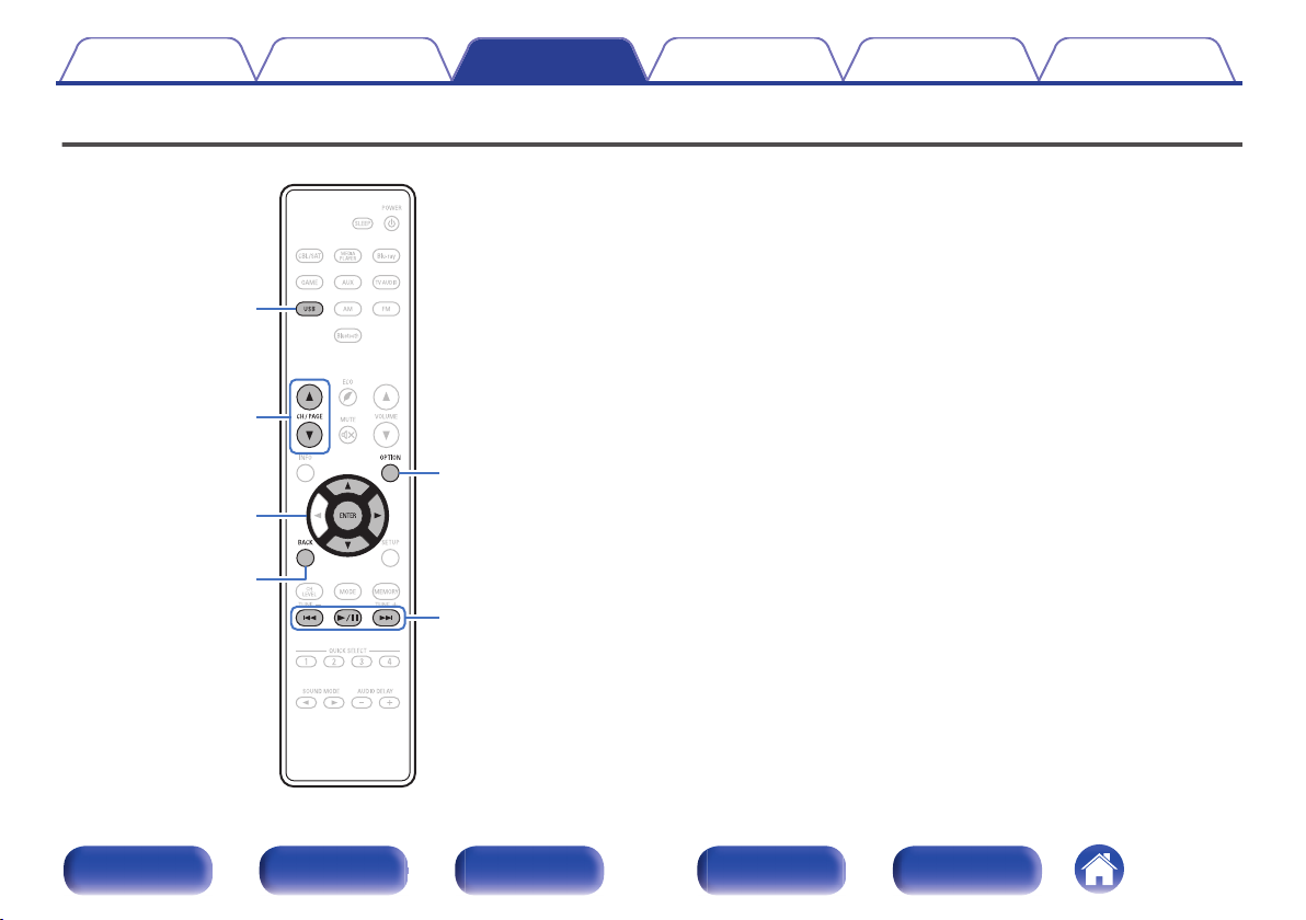
Playing a USB memory device
Playing back music files stored on a USB memory device.
0
Only USB memory devices conforming to mass storage class standards
0
can be played on this unit.
This unit is compatible with USB memory devices in “FAT16” or
0
“FAT32” format.
The audio format types and specifications supported by this unit for
0
playback are as follows.
See “Playing back a USB memory devices” for details. (v p. 128)
WMA
0
MP3
0
WAV
0
MPEG-4 AAC
0
FLAC
0
Apple Lossless
0
AIFF
0
Front panel Display Rear panel Remote Index
42

OPTION
[1/2]
USB
Option
Folder
Music
Contents
Connections Playback Settings Tips Appendix
Playing files stored on USB memory devices
Connect the USB memory device to the USB port.
1
(v p. 35)
Press USB to switch the input source to “USB”.
2
Use ui p to select the file to be played, then press
3
ENTER.
Playback starts.
Operation buttons
1/3
8 9
ENTER
u i
CH/PAGE d f
NOTE
Note that Denon will accept no responsibility whatsoever for any problems arising
0
with the data on a USB memory device when using this unit in conjunction with the
USB memory device.
o
Operations accessible through the option
Playback / Pause
Skip to previous track / Skip to next track
(Press and hold) Fast-reverse / Fastforward
Playback / Pause
(Press and hold) Stop
Skip to previous track / Skip to next track
(Press and hold) Fast-reverse / Fastforward
Switch to the previous page/next page in
the list display
Function
menu
“Performing repeat playback (Repeat)” (v p. 56)
0
“Performing random playback (Random)” (v p. 56)
0
“Adjusting the tone (Tone)” (v p. 57)
0
“Displaying your desired video during audio playback (Video
0
Select)” (v p. 59)
Front panel Display Rear panel Remote Index
43

Bluetooth
8 9
OPTION
1/3
BACK
ui
ENTER
Contents Connections Playback Settings Tips Appendix
Listening to music on a Bluetooth device
Music files stored on Bluetooth devices such as smartphones, digital
music players, etc. can be enjoyed on this unit by pairing and connecting
this unit with the Bluetooth device.
Communication is possible up to a range of about 32.8 ft/10 m.
NOTE
To play back music from a Bluetooth device, the Bluetooth device needs to
0
support the A2DP profile.
Front panel Display Rear panel Remote Index
44

Pairing Mode
Cancel
Turn on Bluetootn from your mobile device’s
settings menu, then select"Denon AVR-S570BT"
when it appears in the device list.
Contents Connections Playback Settings Tips Appendix
Playing music from Bluetooth device
In order to enjoy music from a Bluetooth device on this unit, the Bluetooth
device must first be paired with this unit.
Once the Bluetooth device has been paired, it does not need to be paired
again.
Press Bluetooth to switch the input source to
1
“Bluetooth”.
When using for the first time, the unit will go into the pairing mode
automatically and “Pairing...” will appear on the display of the unit.
Activate the Bluetooth settings on your mobile device.
2
Select this unit when its name appears in the list of
3
devices displayed on the screen of the Bluetooth
device.
Connect to the Bluetooth device while “Pairing” is being displayed
on the display of the unit.
Perform the connection with the Bluetooth device close to the unit
(about 3.3 ft/1 m).
When a number appears on the display of this unit,
4
check that it is the same number as that shown on the
screen of the Bluetooth device and then select “Pair”
for both the Bluetooth device and the unit.
At the end of the pairing, the device name appears on the display of
this unit.
Play music using any app on your Bluetooth device.
5
The Bluetooth device can also be operated with the remote
0
control of this unit.
The next time the input source is switched to Bluetooth, this unit
0
automatically connects to the last Bluetooth device that was
connected.
Enter “0000” when the password is requested on the screen of the Bluetooth
0
device.
Front panel Display Rear panel Remote Index
45

Contents
Connections Playback Settings Tips Appendix
Operation buttons Function
1/3
Playback / Pause
Skip to previous track / Skip to next track
8 9
(Press and hold) Fast-reverse / Fastforward
ENTER
Playback / Pause
(Press and hold) Stop
Skip to previous track / Skip to next track
u i
(Press and hold) Fast-reverse / Fastforward
English letters, numbers and certain symbols are displayed. Incompatible
0
characters are displayed as “.” (period).
NOTE
To operate the Bluetooth device with the remote control of this unit, the Bluetooth
0
device needs to support the AVRCP profile.
The remote control of this unit is not guaranteed to work with all Bluetooth devices.
0
Depending on the type of Bluetooth device, this unit outputs audio that is coupled
0
to the volume setting on the Bluetooth device.
o
Operations accessible through the option
menu
“Pairing with other Bluetooth devices” (v p. 47)
0
“Performing repeat playback (Repeat)” (v p. 56)
0
“Performing random playback (Random)” (v p. 56)
0
“Adjusting the tone (Tone)” (v p. 57)
0
“Displaying your desired video during audio playback (Video
0
Select)” (v p. 59)
Front panel Display Rear panel Remote Index
46

Contents Connections Playback Settings Tips Appendix
Pairing with other Bluetooth devices
This unit can be paired with a maximum of 8 Bluetooth devices. When a 9th
Pair a Bluetooth device with this unit.
Activate the Bluetooth settings on your mobile device.
1
Press OPTION when the input source is “Bluetooth”.
2
The option menu screen is displayed.
Use ui to select “Pairing Mode”, then press ENTER.
3
The device will go into the pairing mode.
Select this unit when its name appears in the list of
4
devices displayed on the screen of the Bluetooth
device.
When a number appears on the display of this unit,
5
check that it is the same number as that shown on the
screen of the Bluetooth device and then select “Pair”
for both the Bluetooth device and the unit.
At the end of the pairing, the device name appears on the display of
this unit.
0
Bluetooth device is paired, it will be registered in place of the oldest registered
device.
Enter “0000” when the password is requested on the screen of the Bluetooth
0
device.
Press and hold the Bluetooth on the remote control for at least 3 seconds to go
0
into pairing mode.
Front panel Display Rear panel Remote Index
47

Contents Connections Playback Settings Tips Appendix
Reconnecting to this unit from a Bluetooth device
After pairing is completed, the Bluetooth device can be connected without
performing any operations on this unit.
This operation also needs to be performed when switching the Bluetooth
device for playback.
If a Bluetooth device is currently connected, deactivate
1
the Bluetooth setting of that device to disconnect it.
Activate the Bluetooth setting of the Bluetooth device
2
to be connected.
Select this unit from the Bluetooth device list on your
3
Bluetooth device.
Play music using any app on your Bluetooth device.
4
When the power of this unit is turned on, the input source will be automatically
0
switched to “Bluetooth” if a Bluetooth device is connected.
When the “Bluetooth Standby” setting of this unit is set to “On”, “Auto-Select”
0
setting of this unit is set to “On”, and a Bluetooth device is connected with the unit
in the standby state, the power of the unit will be turned on automatically.
(v p. 100)
Front panel Display Rear panel Remote Index
48

FM
CH/PAGE
df
AM
MODE
TUNE +, –
MEMORY
uio p
ENTER
OPTION
Contents Connections Playback Settings Tips Appendix
Listening to FM/AM broadcasts
You can use the built-in tuner of this unit to listen to FM broadcasts and
AM broadcasts.
Make sure the FM antenna and AM loop antenna are connected to this
unit first.
Front panel Display Rear panel Remote Index
49

OPTION
STEREO
AUTO
CH /TUNE +/-
Tuner
CH 1
FM 92.1 MHz
Tune Preset Option
01 FM 92.10MHz
GDisplay of this unitH
Contents Connections Playback Settings Tips Appendix
Listening to FM/AM broadcasts
Connect the antenna. (“Connecting an FM/AM
1
antenna” (v p. 36))
Press FM or AM to switch the input source to “FM” or
2
“AM”.
G TV screen H
Press MODE to select the tune mode.
3
AUTO
(Default) :
Automatically search for and tune to a
receivable radio station.
Manually change the frequency one
MANUAL:
step at a time each time the button is
pressed.
Press TUNE + or TUNE - to select the station you want
4
listen to.
Scanning is performed until it finds an available radio station. When
it finds a radio station, it stops the scan automatically and tunes in.
The modes for receiving FM broadcasts consists of “AUTO” mode that
0
automatically searches available broadcast stations and “MANUAL” mode that lets
you tune in using buttons to change the frequency. The default setting is “AUTO”.
In “AUTO” mode, you cannot tune in to radio stations if the reception is not good.
If this is the case, then use the “MANUAL” mode to tune in.
Operation buttons Function
CH/PAGE d f
Selects preset radio stations
MODE Switching tune mode
MEMORY Register presets
TUNE +, - Selects the radio station (up/down)
Front panel Display Rear panel Remote Index
50

Contents Connections Playback Settings Tips Appendix
o
Operations accessible through the option
menu
“Tuning in to stations and presetting them automatically (Auto
0
Preset)” (v p. 51)
“Skipping preset broadcast stations (Preset Skip)” (v p. 53)
0
“Adjusting the tone (Tone)” (v p. 57)
0
“Displaying your desired video during audio playback (Video
0
Select)” (v p. 59)
Tuning in to stations and presetting them automatically (Auto Preset)
A maximum of 56 radio stations can be automatically preset.
Press OPTION when the input source is “FM”.
1
The option menu screen is displayed.
Use ui to select “Auto Preset”, then press ENTER.
2
The unit starts to tune in to radio stations automatically and preset
them.
When presetting is completed, “Completed” is displayed for about
0
5 seconds and the option menu screen turns off.
The preset memory is overwritten.
0
Front panel Display Rear panel Remote Index
51

Contents Connections Playback Settings Tips Appendix
Presetting the current broadcast station (Preset Memory)
Your favorite broadcast stations can be preset so that you can tune them
in easily.
Up to 56 stations can be preset.
Tune in the broadcast station you want to preset.
1
(“Listening to FM/AM broadcasts” (v p. 50))
Press MEMORY.
2
Use ui to select the channel you want to preset.
3
Press MEMORY.
4
The current broadcast station that is preset.
To preset other stations, repeat steps 1 to 4.
0
Channel Default settings
1 – 8
9 – 16
17 – 24
25 – 32
33 – 40
41 – 48
49 – 56
92.10 / 92.30 / 92.50 / 92.70 / 93.10 / 93.50 / 93.70 / 94.10
MHz
94.30 / 94.50 / 94.70 / 94.90 / 95.10 / 95.30 / 95.50 / 95.70
MHz
98.10 / 98.30 / 98.50 / 98.70 / 98.90 / 99.10 / 100.10 /
100.30 MHz
100.50 / 100.70 / 100.90 / 101.10 / 101.30 / 101.50 /
101.70 / 101.90 MHz
103.10 / 103.30 / 103.50 / 103.70 / 103.90 / 104.10 /
104.30 / 104.50 MHz
104.70 / 104.90 / 105.10 / 105.30 / 105.50 / 105.70 /
105.90 / 106.10 MHz
106.30 / 106.50 / 106.70 / 106.90 / 107.10 / 107.30 /
107.50 / 107.90 MHz
Listening to preset stations
Use CH/PAGE df to select the desired preset channel.
1
You can also select preset broadcast stations by pressing TUNER PRESET CH +
0
or TUNER PRESET CH - on the main unit.
Front panel Display Rear panel Remote Index
52

Contents Connections Playback Settings Tips Appendix
Skipping preset broadcast stations (Preset Skip)
Perform auto preset memory to save all the broadcasting stations that can
be received in the memory. Selecting a broadcast station becomes easier
by skipping unnecessary memories.
Press OPTION when the input source is “FM” or “AM”.
1
The option menu screen is displayed.
Use ui to select “Preset Skip”, then press ENTER.
2
The “Preset Skip” screen is displayed.
Use ui to select the group of broadcast stations you
3
want to skip.
Skip all the broadcast stations that are included in the selected
group “CH z-z”.
(z is the selected group number.)
Use o p to select “Skip”.
4
The station you selected is not displayed.
Cancelling Preset Skip
While the “Preset Skip” screen is displayed, use ui to
1
select a group of a broadcast stations to cancel the
skip for.
Use o p to select “On”.
2
The skip is cancelled.
Front panel Display Rear panel Remote Index
53

Contents Connections Playback Settings Tips Appendix
Compatible with the “Denon 500 Series Remote” app
The “Denon 500 Series Remote” app allows you to remotely control the AVR-S570BT from your mobile device when connected via Bluetooth. It is
available for free in the Apple App Store, Google Play or the Amazon Appstore. Make sure you search for “DENON 500 SERIES”.
Front panel Display Rear panel Remote Index
54

uio p
ENTER
OPTION
Contents Connections Playback Settings Tips Appendix
Convenience functions
This section explains how to use convenient functions that can be used for
each input source.
Front panel Display Rear panel Remote Index
55

Contents Connections Playback Settings Tips Appendix
Performing repeat playback (Repeat)
n
Supported input sources : USB / Bluetooth
While content is playing, press OPTION.
1
The option menu screen is displayed.
Use ui to select “Repeat”, then press ENTER.
2
Use o p to select repeat playback mode.
3
Off
(Default):
One: A file being played is played repeatedly.
All:
Folder:
Press ENTER.
4
The display returns to the playback screen.
“Repeat” settings are stored for each input source.
0
Repeat playback mode is canceled.
All files in the folder currently being
played are played repeatedly. (When
the input source is set to “Bluetooth”)
All files in the folder currently being
played are played repeatedly. (When
the input source is set to “USB”)
Performing random playback (Random)
n
Supported input sources : USB / Bluetooth
While content is playing, press OPTION.
1
The option menu screen is displayed.
Use ui to select “Random”, then press ENTER.
2
Use o p to select random playback mode.
3
Off
(Default):
On:
Press ENTER.
4
The display returns to the playback screen.
During random playback, each time playback of a track is completed, another
0
track is randomly selected for playback from tracks in the folder. Therefore, it’s
possible that you may hear a track played back more than once during random
playback.
“Random” settings are stored for each input source.
0
Disable random playback.
Randomly play back all tracks in the
current playback folder.
Front panel Display Rear panel Remote Index
56

Contents
Connections Playback Settings Tips Appendix
Adjusting the tone (Tone)
Adjusts the tonal quality of the front speakers.
Press OPTION.
1
The option menu screen is displayed.
Use ui to select “Tone”, then press ENTER.
2
The “Tone” screen is displayed.
Use o p to set the tone control function to on/off.
3
On: Allow tone adjustment (bass, treble).
Off
(Default):
Select “On” in step 3 and press i to select the sound
4
range to be adjusted.
Bass: Adjust bass.
Treble: Adjust treble.
Playback without tone adjustment.
Use o p to adjust the tone, then press ENTER.
5
-6 dB – +6 dB (Default : 0 dB)
o
Operating the unit
n
Setting the tone control function
Press TONE CONTROL ON/OFF.
n
Select the range for which to adjust the tone
Press BASS/TREBLE.
n
Adjusting the tone
Press ADJUST 0 or ADJUST 1.
“Tone” settings are stored for each input source.
0
This cannot be set when the sound mode is set to “Direct” or “Pure Direct”.
0
You cannot set this when no audio signal is input or in the menu “HDMI Audio Out”
0
is set to “TV”. (v p. 80)
Front panel Display Rear panel Remote Index
57

Contents Connections Playback Settings Tips Appendix
Adjusting audio delay (Audio Delay)
Compensates for incorrect timing between video and audio.
Press OPTION.
1
The option menu screen is displayed.
Use ui to select “Audio Delay”, then press ENTER.
2
The “Audio Delay” screen is displayed.
Use o p to adjust the timing.
3
0 ms – 200 ms (Default : 0 ms)
“Audio Delay” settings are stored for each input source.
0
The “Audio Delay” settings can be set even if AUDIO DELAY + or AUDIO DELAY -
0
is pressed on the remote control unit.
Optimizing the night time listening volume (Night Mode)
Compress dynamic range (difference between loud and soft sounds).
This can be set when a Dolby Digital signal is input.
Press OPTION.
1
The option menu screen is displayed.
Use ui to select “Night Mode”, then press ENTER.
2
The Night Mode setting screen is displayed.
Use o p to select “Night Mode”, then press ENTER.
3
Low : Set the adjusted value to low.
Medium : Set the adjusted value to middle.
High : Set the adjusted value to high.
Auto :
Off
(Default):
“Auto” can be set when a Dolby TrueHD signal is input.
0
The default setting is “Off”.
0
Automatic dynamic range compression
on/off control according to the source.
Do not set.
Front panel Display Rear panel Remote Index
58

Contents Connections Playback Settings Tips Appendix
Displaying your desired video during audio playback (Video Select)
This unit can display video from a different source on TV during audio
playback. You can set this for each input source.
n
Supported input sources :
USB / FM / AM / Bluetooth
Press OPTION during audio playback.
1
The option menu screen is displayed.
Use ui to select “Video Select”, then press ENTER.
2
Use o p to select the Video Select mode.
3
Off
(Default):
On: Enable Video Select mode.
Use o p to select the input source for video you want
4
to play back, then press ENTER.
“Video Select” settings are stored for each input source.
0
Front panel Display Rear panel Remote Index
Disable Video Select mode.
59

SOUND MODE
0 1
Contents
Connections Playback Settings Tips Appendix
Selecting a sound mode
This unit allows you to enjoy various kinds of surround and stereo
playback modes.
Multi-channel audio formats are provided on popular movie and music
disc formats such as Blu-ray and DVD, as well as being supported by
digital broadcasting, and even by streaming movies.
This unit supports playback of almost all of these multi-channel audio
formats. It also supports surround playback of audio formats other than
multi-channel audio such as 2-channel stereo audio.
For audio formats recorded on a disc, see the disc jacket or label.
0
Selecting a sound mode
Press SOUND MODE 0 1 to select a sound mode.
1
If the content played back does not support the previously selected sound mode,
0
the most appropriate sound mode for the content is automatically selected.
You can also select the sound mode by pressing SOUND MODE on the main unit.
0
Front panel Display Rear panel Remote Index
60

Contents Connections Playback Settings Tips Appendix
Description of sound mode types
o
Dolby sound mode
Sound mode type Description
Dolby PLg This mode can be selected when the Dolby PLg decoder is used to play back 2-channel sources in 5.1-channel surround
Dolby Digital This mode can be selected when playing sources recorded in Dolby Digital.
Dolby TrueHD This mode can be selected when playing sources recorded in Dolby TrueHD.
Dolby Digital Plus This mode can be selected when playing sources recorded in Dolby Digital Plus.
DTS sound mode
Sound mode type Description
DTS Neo:6 This mode can be selected when a DTS Neo:6 decoder is used to play back 2-channel source in 5.1-channel surround
DTS Surround This mode can be selected when playing sources recorded in DTS.
DTS-HD This mode can be selected when playing sources recorded in DTS-HD.
PCM multi-channel sound mode
Sound mode type Description
Multi Ch In This mode can be selected when playing multi-channel PCM sources.
sound with an enveloping surround sound experience.
sound.
Front panel Display Rear panel Remote Index
61

Contents Connections Playback Settings Tips Appendix
Original sound mode
Sound mode type Description
Multi Ch Stereo This mode is for enjoying stereo sound from all speakers.
Virtual This mode lets you experience an expansive surround sound effect when playing back through just the front (L/R)
Stereo sound mode
Sound mode type Description
Stereo This mode plays 2-channel stereo audio with no additional surround sound processing.
Direct sound mode
Sound mode type Description
Direct This mode plays back audio as recorded in the source.
Pure Direct This mode plays back an even higher quality sound than the “Direct” mode.
In Direct and Pure Direct sound modes, the following items cannot be adjusted.
0
Tone (v p. 57)
0
Restorer (v p. 77)
0
Room EQ (v p. 79)
0
speakers only, and when listening with stereo headphones.
Sound is output from the front left and right speakers, and subwoofer if connected.
0
When multi-channel signals are inputted, they are mixed down to 2-channel audio and are played back with no
0
additional surround sound processing.
The following circuits are stopped in order to further improve sound quality.
Display indicator circuit of the main body (display will go off.)
0
NOTE
When the Pure Direct mode has been selected, the display turns off after about 5 seconds.
0
Front panel Display Rear panel Remote Index
62

q w
Contents
o
Views on the display
Shows a decoder to be used.
A
In the case of the Dolby Digital decoder, “
0
In the case of the Dolby Digital Plus decoder, “ ” is
0
displayed.
Shows the name of the input source being played back.
B
Connections Playback Settings Tips Appendix
” is displayed.
Front panel Display Rear panel Remote Index
63
Contents Connections Playback Settings Tips Appendix
HDMI control function
A recent addition to the HDMI standard is CEC (Consumer Electronics Control), which allows control signals from one device to communicate with
another device via the HDMI cable connection.
Setting procedure
Enable the HDMI control function of this unit.
1
Set “HDMI Control” to “On”. (v p. 81)
Turn the power on for all the devices connected by
2
HDMI cable.
Set the HDMI control function for all devices connected
3
by HDMI cable.
Please consult the operating instructions for the connected
0
devices to check the settings.
Carry out steps 2 and 3 should any of the devices be unplugged.
0
Switch the television input to the HDMI input connected
4
to this unit.
Front panel Display Rear panel Remote Index
64
Switch the input source of this unit to check that video
5
from the player connected by HDMI is played back
correctly.
When you turn the TV’s power to standby, check that
6
the power of this unit also goes to standby.
NOTE
Some functions may not operate depending on the connected TV or player. Check
0
the owner’s manual of each device for details beforehand.

CH LEVEL
uio p
Contents Connections Playback Settings Tips Appendix
Adjusting the volume of each channel to match the input source (Channel Level Adjust)
The volume of each channel can be changed while listening to music. You
can set this for each input source.
Press CH LEVEL.
1
The “Channel Level Adjust” screen is displayed.
Use ui to select the channel that you wish to adjust.
2
Use o p to adjust the volume.
3
–12.0 dB – +12.0 dB (Default : 0.0 dB)
Select “Reset” and press ENTER if you want to restore the adjustment values of
0
the various channels to “0.0 dB” (default).
Headphone volume can be adjusted when a headphone is connected.
0
“Channel Level Adjust” settings are stored for each input source.
0
You can only set this for speakers that output audio. In addition, you cannot set
0
this when in the menu “HDMI Audio Out” is set to “TV”. (v p. 80)
Front panel Display Rear panel Remote Index
65

SLEEP
Contents Connections Playback Settings Tips Appendix
Sleep timer function
You can have the power automatically switched to standby once a set time
has elapsed. This is convenient for viewing and listening while going to
sleep.
Front panel Display Rear panel Remote Index
66

Contents Connections Playback Settings Tips Appendix
o
Using the sleep timer
Press SLEEP and display the time you want to set.
1
The SLEEP indicator lights up on the display and the sleep timer
0
starts.
You can set the sleep timer in the range from 10 to 120 minutes in
0
steps of 10 minutes.
Checking the remaining time
Press SLEEP when the sleep timer is in operation.
The remaining time appears on the display.
o
To cancel the sleep timer
Press SLEEP to select “Off”.
The SLEEP indicator on the display turns off.
You can also set the sleep timer by pressing SLEEP on the main unit.
0
The sleep timer setting is canceled when the unit switches to standby mode.
0
NOTE
The sleep timer function cannot turn off the power of devices connected to this
0
unit. To turn off the power of those connected devices, set up sleep timers on the
connected devices themselves.
Front panel Display Rear panel Remote Index
67

QUICK
SELECT
1 – 4
Contents Connections Playback Settings Tips Appendix
Quick select plus function
Settings such as the input source, volume level and sound mode can be
registered to the QUICK SELECT 1 - 4 buttons.
You can simply press one of the registered QUICK SELECT buttons in
subsequent playbacks to switch to the group of saved settings in a batch.
By saving frequently used settings at the QUICK SELECT 1 – 4 buttons,
you will always be able to easily call up the same playback environment.
Front panel Display Rear panel Remote Index
68

Contents Connections Playback Settings Tips Appendix
Calling up the settings
Press QUICK SELECT.
1
The Quick Select settings registered to the button you pressed are
called up.
The default settings for the input source are as shown below.
0
Button Input source
QUICK SELECT 1 CBL/SAT
QUICK SELECT 2 Blu-ray
QUICK SELECT 3 Game
QUICK SELECT 4 Bluetooth
Volume is not registered to Quick Select Plus in the factory default settings.
0
See “Changing the settings” to register volume to Quick Select Plus.
(v p. 69)
Changing the settings
Set the items below to the settings you want to
1
register.
Input source (v p. 40)
A
Volume (v p. 41)
B
Sound mode (v p. 60)
C
Room EQ (v p. 79)
D
Restorer (v p. 77)
E
Video Select (v p. 59)
F
Press and hold the desired QUICK SELECT until
2
“Quickz Memory” appears on the display.
The current settings will be memorized.
z is displayed the number for the QUICK SELECT button you
pressed.
Press and hold QUICK SELECT while a radio station is being received is
0
being played back with any of the following sources, the current radio
station is memorized.
Tuner
0
The items registered to Quick Select can be selected. (“Quick Select
0
Options” (v p. 101))
Front panel Display Rear panel Remote Index
69

Contents Connections Playback Settings Tips Appendix
Menu map
When using menu operations, connect this unit to a TV and operate this unit while viewing the TV.
The recommended settings are configured for this unit by default. You can customize this unit based on your existing system and your preferences.
Setting items Detailed items Description Page
Surround Parameter Adjusts surround sound parameters. 74
Audio
Video
Restorer Expands the low and high frequency components of compressed audio content such as
Volume Make volume settings. 78
Room EQ Set whether to use the equalizer or not. 79
HDMI Setup Makes settings for HDMI Audio Out, HDMI Pass Through and HDMI Control settings. 80
HDMI Upscaler Sets the mode for upscaling 1080p and 4K HDMI content to 8K. 83
Screen Saver Sets the screen saver setting. 84
4K/8K Signal Format Sets signal format options for your 4K or 8K video equipment. 84
HDCP Setup Sets the HDCP version for each HDMI input source. 86
MP3 files to enable richer audio playback.
77
Front panel Display Rear panel Remote Index
70

Contents Connections Playback Settings Tips Appendix
Setting items Detailed items Description Page
Input Assign Changes input connector assignment. 87
Source Level Adjusts the playback level of the audio input. 87
Input Select Sets the audio input mode and decode mode. 88
Inputs
Auto Setup The acoustic characteristics of the connected speakers and listening room are
measured and the optimum settings are made automatically.
Manual Setup Sets up the speakers manually or changes the “Auto Setup” settings. 94
Speakers
89
Front panel Display Rear panel Remote Index
71

Contents Connections Playback Settings Tips Appendix
Setting items Detailed items Description Page
Language Changes the language of the display on the TV screen. 98
ECO Configures the ECO Mode and Auto Standby energy-saving functions. 98
Bluetooth Configures the Bluetooth settings. 100
Quick Select Options Sets the items registered to Quick Select. 101
General
Setup Assistant
Front Display Makes settings related to the display on this unit. 102
Firmware Update the firmware of this unit. 102
Setup Lock Protects settings from inadvertent changes. 103
Reset Various settings are reset to the factory default values. 103
Begin Setup... Performs basic installation/connections/settings from the beginning according to the
guidance indicated on the TV screen.
Page 7 of
the separate
manual
“Quick Start
Guide”
Front panel Display Rear panel Remote Index
72

uio p
ENTER
SETUP
BACK
Contents Connections Playback Settings Tips Appendix
Menu operations
Press SETUP.
1
The menu is displayed on the TV screen.
Use ui to select the menu to be set or operated, then
2
press ENTER.
Use o p to change to desired setting.
3
Press ENTER to enter the setting.
4
To return to the previous item, press BACK.
0
Exiting the menu, press SETUP while the menu is displayed. The
0
menu display disappears.
Front panel Display Rear panel Remote Index
73

Contents Connections Playback Settings Tips Appendix
Audio
Make audio-related settings.
o
Surround Parameter
You can adjust the surround audio sound field effects to match your
preferences.
The items (parameters) that can be adjusted depend on the signal being
input and the currently set sound mode. For details on the adjustable
parameters, see “Sound modes and surround parameters” (v p. 132).
Some setting items cannot be set while playback is stopped. Make the settings
0
during playback.
“Surround Parameter” settings are stored for each sound mode.
0
Mode
Set the sound mode according to the input signal.
n
Dolby PLg Mode
Movie :
Music :
Game :
Pro Logic : Dolby Pro Logic playback mode.
n
DTS Neo: 6 mode
Cinema :
Music :
“Music” mode is also effective for video sources that contain a lot of stereo
0
music.
Switches to the sound mode suitable for
enjoying movies and TV programs.
Switches to the sound mode suitable for
enjoying music.
Switches to the sound mode suitable for
enjoying games.
Switches to the sound mode suitable for
enjoying movies and TV programs.
Switches to the sound mode suitable for
enjoying music.
Front panel Display Rear panel Remote Index
74

Contents Connections Playback Settings Tips Appendix
o
Dynamic Compression
Compress dynamic range (difference between loud and soft sounds).
Auto:
Low / Medium / High: These set the compression level.
Off
(Default):
“Auto” can only be set when Dolby TrueHD signals are input.
0
Automatic dynamic range compression
on/off control according to source.
Dynamic range compression is always
off.
o
Low Frequency Effects
Adjust the low frequency effects level (LFE).
-10 dB – 0 dB (Default : 0 dB)
For proper playback of the different sources, we recommend setting to the
0
values below.
Dolby Digital sources : 0 dB
0
DTS movie sources : 0 dB
0
DTS music sources: -10 dB
0
o
Center Image
Distributes the dialogue output from the center channel to the front left
and right channels and widens the sound image in the front.
0.0 – 1.0 (Default : 0.3)
You can set this when the sound mode is DTS Neo:6 in the “Music” mode.
0
The smaller the value, the more dialogue is concentrated on the center
0
channel. The larger the value, the more dialogue is distributed to front left and
right channels, and the more the sound image widens in the front.
Front panel Display Rear panel Remote Index
75

Contents Connections Playback Settings Tips Appendix
o
Panorama
The front sound field is expanded further towards the back to create a
seamlessly inclusive sound impression.
On: Use “Panorama”.
Off
(Default):
You can set this when the sound mode is Dolby PLg in the “Music” mode.
0
Do not use “Panorama”.
o
Dimension
Shift sound image center to front or rear to adjust playback balance.
0 – 6 (Default : 3)
You can set this when the sound mode is Dolby PLg in the “Music” mode.
0
As you set a smaller number, the surround sound field shifts backward; as you
0
set a larger number, the surround sound field shifts forward.
o
Center Width
Distributes the dialogue output from the center channel to left and right
channels and widens the sound image in the front.
0 – 7 (Default : 3)
You can set this when the sound mode is Dolby PLg in the “Music” mode.
0
The smaller the value, the more dialogue is concentrated on the center
0
channel. The larger the value, the more dialogue is distributed to front left and
right channels, and the more the sound image widens in the front.
Front panel Display Rear panel Remote Index
76

Contents Connections Playback Settings Tips Appendix
o
Subwoofer
Turn subwoofer output on and off.
On
(Default):
Off: The subwoofer is not used.
You can set this when the sound mode is “Direct” or “Stereo” and in the menu
0
“Subwoofer Output” is set to “LFE+Main”. (v p. 97)
o
Set Defaults
The “Surround Parameter” settings are returned to the default settings.
The subwoofer is used.
Restorer
Compressed audio formats such as MP3 and WMA (Windows Media
Audio) reduce the amount of data by eliminating signal components that
are hard for the human ear to hear. The “Restorer” function generates the
signals eliminated upon compression, restoring the sound to conditions
near those of the original sound before compression. It also restores the
original bass characteristics for a rich and expanded tonal range.
On: Use “Restorer”.
Off
(Default):
This item can be set with analog signals or PCM signal (Sample Rate = 44.1/48
0
kHz) is input.
This cannot be set when the sound mode is set to “Direct” or “Pure Direct”.
0
“Restorer” settings are stored for each input source.
0
Do not use “Restorer”.
Front panel Display Rear panel Remote Index
77

Contents Connections Playback Settings Tips Appendix
o
Volume
Make volume settings.
o
Scale
Set how volume is displayed.
0 - 98
(Default):
–79.5 dB – 18.0 dB:
Display in the range 0 (Min) to 98.
Display ---dB (Min), in the range –79.5 dB
to 18.0 dB.
Limit
Make a setting for maximum volume.
60 – 80 (–20 dB – 0 dB)
Off (Default)
The dB value is displayed when the “Scale” setting is “ –79.5 dB – 18.0 dB”.
0
(v p. 78)
o
Power On Level
Define the volume setting that is active when the power is turned on.
Last
(Default):
Mute:
1 – 98 (–79 dB – 18 dB) : The volume is adjusted to the set level.
The dB value is displayed when the “Scale” setting is “ –79.5 dB – 18.0 dB”.
0
(v p. 78)
Use the memorized setting from the last
session.
Always use the muting on condition when
power is turned on.
Front panel Display Rear panel Remote Index
78

Contents Connections Playback Settings Tips Appendix
o
Mute Level
Set the amount of attenuation when muting is on.
Full
(Default):
–40 dB : The sound is attenuated by 40 dB down.
–20 dB : The sound is attenuated by 20 dB down.
The sound is muted entirely.
Room EQ
Set whether to use the equalizer or not.
On: Use “Room EQ”.
Off
(Default):
This item can be selected after Auto Setup has been performed.
0
This cannot be set when the sound mode is set to “Direct” or “Pure Direct”.
0
Do not use “Room EQ”.
Front panel Display Rear panel Remote Index
79

Contents
Connections Playback Settings Tips Appendix
Video
Make video-related settings.
HDMI Setup
Make settings for HDMI Audio Out, HDMI Pass Through and HDMI
Control settings.
NOTE
When “HDMI Pass Through” and “HDMI Control” is set to “On”, it consumes more
0
standby power. (“HDMI Pass Through” (v p. 81), “HDMI Control” (v p. 81))
If you are not using this unit for an extended period, it is recommended that you
unplug the power cord from the power outlet.
o
HDMI Audio Out
Select HDMI audio output device.
AVR
(Default):
TV:
When the HDMI Control function is activated, priority is given to the TV audio
0
setting. (v p. 64)
When the power of this unit is on and “HDMI Audio Out” is set to “TV”, audio is
0
output as 2-channel from the HDMI OUT connector.
Play back through speakers connected to
the unit.
Play back through TV connected to the
unit.
Front panel Display Rear panel Remote Index
80

Contents Connections Playback Settings Tips Appendix
o
HDMI Pass Through
Selects how this unit will transmit HDMI signals to the HDMI output in
standby power mode.
On
(Default):
Off:
o
Pass Through Source
Sets the HDMI connector that inputs HDMI signals when in standby.
Last:
CBL/SAT / Media Player /
Blu-ray / Game
(Default: CBL/SAT):
“Pass Through Source” can be set when “HDMI Pass Through” is set to “On”
0
or “HDMI Control” is set to “On”. (“HDMI Pass Through” (v p. 81), “HDMI
Control” (v p. 81))
Transmits the selected HDMI input
through this unit’s HDMI output when this
unit is in standby power mode.
No HDMI signals are transmitted through
this unit’s HDMI output in standby power
mode.
The most recently used input source will
go into standby mode.
Pass through the selected input source.
o
HDMI Control
You can link operations with devices connected to HDMI and
compatible with HDMI Control.
On: Use HDMI Control function.
Off
(Default):
Please consult the operating instructions for each connected device to check
0
the settings.
When “HDMI Control” is set to “On”, this unit’s power status can be linked to
0
that of the TV and this unit’s volume can be controlled using the TV remote
control.
Refer to “HDMI Control function” for more information about the HDMI Control
0
function. (v p. 64)
NOTE
If the “HDMI Control” settings have been changed, always reset the power to
0
connected devices after the change.
Do not use HDMI Control function.
Front panel Display Rear panel Remote Index
81

Contents Connections Playback Settings Tips Appendix
o
ARC
On the TV connected to the HDMI MONITOR connector, set whether
to receive sound from the TV via HDMI.
On: Use ARC function.
Off
(Default):
If using this function, use a TV compatible with ARC (Audio Return Channel)
0
and enable the HDMI Control function of the TV.
When “ARC” is set to “On”, this unit’s volume can be controlled using the TV
0
remote control, even when “HDMI Control” is set to “Off” for this unit.
NOTE
If the “ARC” settings have been changed, always reset the power to
0
connected devices after the change.
Using an eARC function-compatible television enables audio playback from
0
the speaker connected to this unit, regardless of “ARC” settings in the menu.
Do not use ARC function.
o
TV Audio Switching
Sets automatic switching to the “TV Audio” input when a TV connected
via HDMI sends an appropriate CEC control command to this unit.
On
(Default):
Off:
“TV Audio Switching” can be set when “HDMI Control” is set to “On”.
0
(v p. 81)
Select the “TV Audio” input automatically
when receiving a command from the TV.
Do not select the “TV Audio” input
automatically when receiving a command
from the TV.
Front panel Display Rear panel Remote Index
82

Contents Connections Playback Settings Tips Appendix
o
Power Off Control
Links the power standby of this unit to external devices.
All
(Default):
Video:
Off: This unit does not link with power to a TV.
“Power Off Control” can be set when “HDMI Control” is set to “On”. (v p. 81)
0
If power to a connected TV is turned off
independently of the input source, power
to this unit is automatically set to standby.
With an input source being selected that
is assigned either “HDMI” or “VIDEO”,
when you turn the power of the TV off,
power to this unit is automatically set to
standby. (v p. 87)
HDMI Upscaler
Sets the mode for upscaling 1080p and 4K HDMI content to 8K.
Auto:
Off
(Default):
This item can be set when “HDMI” is assigned for each input source.
0
This function is not effective when the input signal is “x.v.Color”, 3D, sYCC601
0
color, Adobe RGB color, Adobe YCC601 color, computer resolutions, compressed
video or HDR.
Upscale 1080p and 4K HDMI video to 8K
based on the monitor’s capabilities.
8K upscaler is disabled.
Front panel Display Rear panel Remote Index
83

Contents Connections Playback Settings Tips Appendix
Screen Saver
Select the screen saver setting.
A screen saver is activated if no operation is performed for more than 5
minutes when no video signal is input or when the same screen (e.g. the
setup menu) is displayed.
Use uio p to clear the screen saver.
On: Turns screen saver on.
Off
(Default):
The screen saver is activated in the following cases.
0
When the setup menu is displayed
0
When no video signal is input
0
When the USB, Bluetooth or Tuner playback screen is displayed
0
Turns screen saver off.
4K/8K Signal Format
Set the format of 4K and 8K signal to be played back by this unit when the
TV or playback device connected to this unit is HDMI 4K or 8K signal
compatible.
o
4K/8K Signal Format
Sets the signal format options for devices connected to each input on
this unit.
Standard:
Enhanced
(Default):
8K Enhanced:
Select if your TV and the source device
support 4K 60Hz 4:2:0 8 bit video signals.
Select if your TV, the source device, and
cables support high quality 4K 60Hz
4:4:4 8 bit, 4:2:2 or 4:2:0 10 bit video
signals.
Select if your TV, the source device, and
cables support high quality 8K 60Hz or
4K 120Hz video signals.
Front panel Display Rear panel Remote Index
84

Contents Connections Playback Settings Tips Appendix
GRelation between the “4K/8K Signal Format” setting and supported
resolutionsH
Support
Resolution
4K 24Hz,
4K 30Hz,
4K 25Hz
4K 60Hz,
4K 50Hz
4K 120Hz,
4K 100Hz
Color
Space
RGB /
YCbCr 4:4:4
Pixel
Depth
8 bit
10,12 bit –
YCbCr 4:2:2 12 bit
YCbCr 4:2:0
RGB /
YCbCr 4:4:4
8 bit
10,12 bit –
8 bit –
10,12 bit – –
YCbCr 4:2:2 12 bit –
YCbCr 4:2:0
RGB /
YCbCr 4:4:4
8,10,12
bit
8,10 bit – –
4K/8K Signal Format
Standard Enhanced
P P P
P P
P P P
P P P
P P
P P
P P
– –
8K
Enhanced
YCbCr 4:2:2 12 bit – –
8,10,12
bit
– –
8,10 bit – –
8K 24Hz,
8K 30Hz,
8K 25Hz
YCbCr 4:2:0
RGB /
YCbCr 4:4:4
YCbCr 4:2:2 12 bit – –
8K 60Hz,
8K 50Hz
YCbCr 4:2:0 8, 10 bit – –
When setting this to “Enhanced”, we recommend using a “Premium High
0
Speed HDMI Cable” or “Premium High Speed HDMI Cable with Ethernet” that
has an “HDMI Premium Certified Cable” label attached to the product
package.
When setting this to “8K Enhanced”, we recommend using a certified “Ultra
0
High Speed HDMI cable”.
When this setting is “8K Enhanced”, configure the television or playback
0
device settings to match this setting.
When this setting is “8K Enhanced”, video may not be output correctly
0
depending on the connected playback device or HDMI cable. In this case,
change this setting to “Enhanced” or “Standard”.
P
P
P
P
P
P
P
P
Front panel Display Rear panel Remote Index
85

Contents Connections Playback Settings Tips Appendix
HDCP Setup
Sets the HDCP version for each HDMI input source.
Video may not be output depending on the HDCP version of your player
and the TV.
If this issue occurs, use this setting to set one version of HDCP. This may
be able to output video.
Auto
(Default):
1.4: Fixes the HDCP version of this unit to 1.4.
2.3: Fixes the HDCP version of this unit to 2.3.
Automatically applies the HDCP version of
this unit according to TV.
Front panel Display Rear panel Remote Index
86
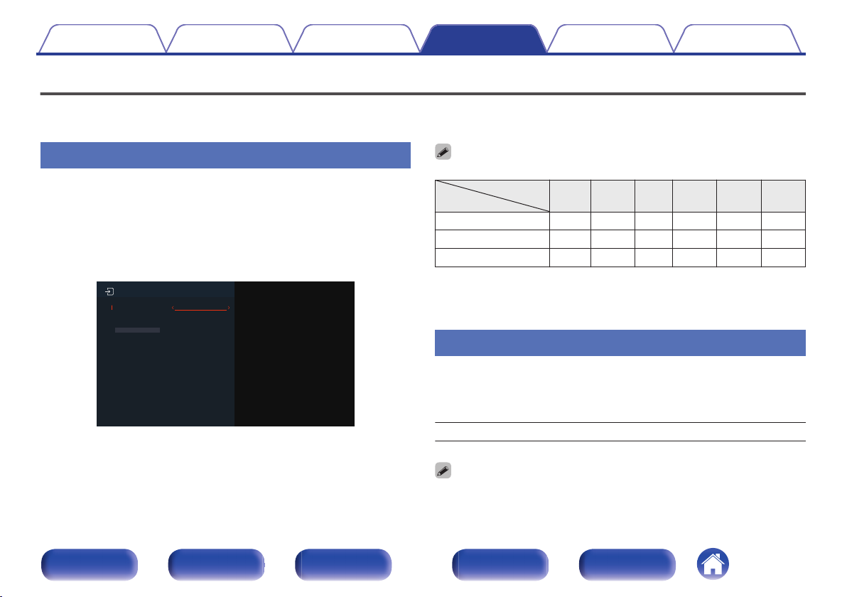
OPTICAL1
OPTICAL2
COAXIAL
TV Audio
AUX
CBL/SAT
Input Assign
Set Defaults
Contents Connections Playback Settings Tips Appendix
Inputs
Perform settings related to input source playback.
You do not have to change the settings to use the unit. Make settings when needed.
Input Assign
By making connections as indicated by the input sources printed on the
audio/video input connectors of this unit, you can just press one of the
input source select buttons to easily play back audio or video from a
connected device.
Please change the assignment of the digital audio input connector when
connecting an input source that differs from that printed to the digital audio
input terminals of this unit.
By default, each item is set as follows.
0
Input source
Input connector
CBL/
SAT
OPTICAL1
OPTICAL2
COAXIAL
o
Set Defaults
The “Input Assign” settings are returned to the default settings.
Source Level
This function corrects the playback level of the selected input source’s
audio input.
Make this setting if there are differences in the input volume levels
between the different sources.
-12 dB – +12 dB (Default : 0 dB)
Front panel Display Rear panel Remote Index
“Source Level” settings are stored for each input source.
0
87
Media
Player
Blu-
ray
Game AUX
TV
Audio
S
S
S

Contents Connections Playback Settings Tips Appendix
o
Input Select
Set the audio input mode and decode mode of each input source.
The input modes available for selection may vary depending on the input
source.
“Input Select” settings are stored for each input source.
0
o
Input Mode
Set the audio input modes for the different input sources.
It is normally recommended to set the audio input mode to “Auto”.
Auto
(Default):
HDMI: Play only signals from HDMI input.
Digital: Play only signals from digital audio input.
Analog: Play only signals from analog audio input.
When digital signals are properly input, the ~ indicator lights on the display.
0
If the ~ indicator does not light, check “Input Assign” and the connections.
(v p. 87)
If “ARC” is set to “On” and a TV compatible with the ARC is connected via the
0
HDMI MONITOR connectors, the input mode whose input source is “TV
Audio” is fixed to ARC.
When an eARC function-compatible television is connected to the HDMI
0
MONITOR connector, the input mode whose input source is “TV Audio” is
fixed to eARC.
Automatically detect input signal and
perform playback.
Decode Mode
Set the audio decode mode for input source.
It is normally recommended to set the audio input mode to “Auto”. But
we recommend changing it to “PCM” or “DTS” if the start of the source
is clipped or noise occurs.
Auto
(Default):
PCM: Decode and play only PCM input signals.
DTS: Decode and play only DTS input signals.
This item can be set for input sources for which the HDMI input connector is
0
assigned or for which “COAXIAL”, “OPTICAL1” or “OPTICAL2” is assigned
under “Input Assign” in the menu. (v p. 87)
Detect type of digital audio input signal
and decode and play automatically.
Front panel Display Rear panel Remote Index
88

FL SW C FR
SRSL
Surround speaker (R)
Surround speaker (L)
Subwoofer
Center speaker
Front speaker (R)
Front speaker (L)
Main listening position
FL
FR
C
SW
SL
SR
Contents Connections Playback Settings Tips Appendix
Speakers
The acoustic characteristics of the connected speakers and listening room are measured and the optimum settings are made automatically. This is called
“Auto Setup”.
You do not have to perform “Auto Setup” when you have already performed “Speaker Setup” in “Setup Assistant”.
To set up the speakers manually, use “Manual Setup” on the menu. (v p. 94)
Auto Setup
To perform measurement, place the Sound calibration microphone in the
main listening position.
Front panel Display Rear panel Remote Index
About the main listening position
o
The main listening position is the position where listeners would
normally sit or where one would normally sit alone within the listening
environment. Before starting “Auto Setup”, place the Sound calibration
microphone in the main listening position.
89

Contents
Connections Playback Settings Tips Appendix
NOTE
Make the room as quiet as possible. Background noise can disrupt the room
0
measurements. Close windows and turn off the power on electronic devices
(radios, air conditioners, fluorescent lights, etc.). The measurements could be
affected by the sounds emitted by such devices.
During the measurement process, place cell phones outside the listening room.
0
Cell phone signals could disrupt the measurements.
Do not stand between the speakers and Sound calibration microphone or allow
0
obstacles in the path while the measurements are being made. Also, install the
Sound calibration microphone at least 20 inches (50 cm) away from the wall.
Failure to do so will result in inaccurate readings.
During the measurement process, audible test tones will come from the speakers
0
and subwoofer(s), but this is part of normal operation. If there is background noise
in the room, these test signals will increase in volume.
Measurement cannot be performed when headphones are connected. Unplug the
0
headphones before performing “Auto Setup”.
Front panel Display Rear panel Remote Index
90

Finish
Measurement
Preparation
Contents Connections Playback Settings Tips Appendix
Procedure for speaker settings (Auto Setup)
Mount the Sound calibration microphone on a tripod
1
and place it in the main listening position.
When installing the Sound calibration microphone, point the tip of
the microphone toward the ceiling and adjust the height to match the
height of the ears of a listener in a seated position.
If using a subwoofer capable of the following
2
adjustments, set up the subwoofer as shown below.
n
When using a subwoofer with a direct mode
Set the direct mode to “On” and disable the volume adjustment
and crossover frequency setting.
n
When using a subwoofer without a direct mode
Make the following settings:
Volume : 12 o’clock position
0
Crossover frequency : Maximum/Highest Frequency
0
Low pass filter : Off
0
Standby mode : Off
0
Front panel Display Rear panel Remote Index
91

When the Sound calibration microphone is
connected, the following screen is displayed.
Auto Setup
Start
Your AVR can automatically measure the
acoustics of your room and the optimize
your speakers.
Contents
Connections Playback Settings Tips Appendix
Connect the Sound calibration microphone to the
3
SETUP MIC jack of this unit.
Select “Start”, then press ENTER.
4
Select “Next”, then press ENTER.
5
Select “Begin Test”, then press ENTER.
6
7
Measurement requires several minutes.
0
NOTE
If “CAUTION” is displayed on TV screen:
0
Go to “Error messages” (v p. 93). Check any related items,
0
and perform the necessary procedures.
n
To cancel Auto Setup
Press BACK to display the popup screen.
A
Press o to select “Yes”, then press ENTER.
B
Unplug the Setup and measurement microphone from
the unit’s SETUP MIC jack.
Do not change the speaker connection or subwoofer volume after
“Auto Setup”. If these are changed, run “Auto Setup” again in order
to configure the optimum equalizer settings.
Front panel Display Rear panel Remote Index
92

Contents Connections Playback Settings Tips Appendix
Error messages
An error message is displayed if “Auto Setup” could not be completed due to speaker placement, the measurement environment, etc. If an error message
is displayed, perform the necessary measures. Be sure to turn off the power before checking speaker connections.
Examples Error details Measures
Front L: None
The displayed speaker could not be detected.
0
Check the connections of the displayed speaker.
0
Front panel Display Rear panel Remote Index
93

Contents Connections Playback Settings Tips Appendix
Manual Setup
Perform when setting the speakers manually or when changing settings made in “Auto Setup”.
This unit can be used without changing “Manual Setup” settings. Please set if necessary.
0
Speaker Layout
Set the speakers to be used.
o
Front
Front is fixed to Yes.
o
Center
Set the Center Speaker.
Yes
(Default):
No: The Center Speaker is not used.
The Center Speaker is used.
o
Surround
Set the Surround Speakers.
Yes
(Default):
No: The Surround Speakers are not used.
o
Subwoofer
Set the presence of a subwoofer.
Yes
(Default):
No: No subwoofer is used.
The Surround Speakers are used.
A subwoofer is used.
Front panel Display Rear panel Remote Index
94

Contents
Connections Playback Settings Tips Appendix
Distances
Set distance from listening position to speakers.
Measure beforehand the distance from the listening position to each
speaker.
o
Step
Set the unit of distance.
1 ft / 0.1 ft (Default : 1 ft)
o
Set Defaults
The “Distances” settings are returned to the default settings.
o
Set the distance
0.0 ft – 60.0 ft
The speakers that can be selected differ depending on the “Speaker Layout”
0
settings. (v p. 94)
Default settings :
0
Front L / Front R / Center / Subwoofer:12.0 ft
Surround L / Surround R:10.0 ft
Set the difference in the distance between the speakers to less than 20.0 ft.
0
Levels
Set the volume of the test tone to be the same at the listening position
when it is output from each speaker.
o
Test Tone Start
A test tone is output from the selected speaker.
While listening to the test tone, adjust the volume output from the
selected speaker.
–12.0 dB – +12.0 dB (Default : 0.0 dB)
The set “Levels” are reflected in all sound modes.
0
When headphones are connected to the PHONES connector on this unit, you
0
cannot set “Levels”.
o
Set Defaults
The “Levels” settings are returned to the default settings.
Front panel Display Rear panel Remote Index
95

Contents Connections Playback Settings Tips Appendix
Crossovers
Set in accordance with the lower limit frequency of the base frequencies
that can be played back through each speaker.
o
Set the crossover frequency
Full Band / 40 Hz / 60 Hz / 80 Hz / 90 Hz / 100 Hz / 110 Hz /
120 Hz / 150 Hz / 200 Hz / 250 Hz (Default : 80 Hz)
The default crossover frequency is “80 Hz”, which will work best with the
0
widest variety of speakers. We recommend setting to a higher frequency that
the crossover frequency when small speakers are used. For example, set to
“250 Hz” when the frequency range of the speakers is 250 Hz – 20 kHz.
Sounds below crossover frequency is cut off in the output from the speaker.
0
The cut off bass frequencies is output from the sub-woofer or front speaker.
When no subwoofer is used, “Front” is fixed to “Full Band”.
0
Front panel Display Rear panel Remote Index
96

Contents Connections Playback Settings Tips Appendix
n
Advanced Setup
Set advanced settings relating to speakers.
o
Subwoofer Output
n
Subwoofer Output
Selects which low frequency signals are sent to the subwoofer outputs.
The subwoofer outputs receive the LFE
LFE
(Default):
LFE+Main:
“Subwoofer Output” can be set when “Speaker Layout” - “Subwoofer” in the
0
menu is set to “Yes”. (v p. 94)
Play music or a movie source and select the mode offering the strongest bass.
0
If “Crossovers” - “Front” and “Center” are set to “Full Band”, and “Subwoofer
0
Output” is set to “LFE”, no sound may be output from the subwoofers,
depending on the input signal or selected sound mode. (v p. 94)
Select “LFE+Main” if you want the bass signals to always be produced from
the subwoofer.
track, plus any redirected bass from
speakers with crossovers set. Use this
setting as the default for home theater
bass management in a typical room.
The subwoofer outputs receive the LFE
track, plus redirected bass, and a copy of
the low frequency signals from all full
band speakers.
Bass Extraction LPF
Set the low pass filter for the bass to be copied from the Full Band
Speaker for each speaker when “Subwoofer Output” is “LFE+Main”.
40 Hz / 60 Hz / 80 Hz / 90 Hz / 100 Hz / 110 Hz / 120 Hz / 150 Hz /
180 Hz / 200 Hz / 250 Hz (Default : 80 Hz)
Setting can only be performed for speakers for which “Crossovers” is set to
0
“Full Band”.
o
LPF for LFE
Selects the crossover point for the LFE channel. Set this when you
want to change the playback frequency (low pass filter point) of the
subwoofer.
80 Hz / 90 Hz / 100 Hz / 110 Hz / 120 Hz/ 150 Hz / 180 Hz /
200 Hz / 250 Hz (Default: 100 Hz)
Front panel Display Rear panel Remote Index
97

Contents
General
Connections Playback Settings Tips Appendix
Make various other settings.
Language
Set the language for display the menu on the TV screen.
English / Français / Español (Default : English)
“Language” can also be set up by the following operation. However, the menu
0
screen is not displayed. Watch the display while configuring the settings.
1. Press and hold the main unit’s TUNER PRESET CH +, TUNER PRESET CH -
and TUNE - for at least 3 seconds.
“V.Format:< NTSC>” appears on the display.
2. Press the main unit’s TUNE +.
“Lang.:<ENGLISH >” appears on the display.
3. Use the main unit’s TUNER PRESET CH + or TUNE - and set the language.
4. Press TUNER PRESET CH - to enter the setting.
ECO
Configure the settings of the ECO Mode and auto standby mode.
o
ECO Mode
This mode can reduce the power consumption when the power of the
unit is on.
On:
Auto
(Default):
Off: No power savings.
When the unit is switching between the different power saving states in “ECO
0
Mode: Auto”, you may notice a click noise from the inside of this unit, this is
normal.
0
Eco mode can also be switched by pressing ECO G on the remote control
unit.
Power savings are always active,
regardless of volume or input signal.
Gives you the best balance between
power savings and maximum power
output:
For low volume levels, the power savings
are active. If you increase the volume
level, the power savings are switched off
automatically, so you can enjoy
maximum output power without
distortion.
Front panel Display Rear panel Remote Index
98

Contents Connections Playback Settings Tips Appendix
o
Power On Default
Set the mode to ECO when the power is on.
Last
(Default):
On:
Auto:
Off:
The ECO Mode will be set to the previous
setting before the power was switched
off.
When power is turned on, the mode will
always be switched to the “ECO Mode” in
“On”.
When power is turned on, the mode will
always be switched to the “ECO Mode” in
“Auto”.
When power is turned on, the mode will
always be switched to the “ECO Mode” in
“Off”.
o
Auto Standby
Set so the unit power automatically switches to standby.
Sets the time for switching to auto standby when there are no audio or
video signals input into this unit.
Before the unit enters standby mode, “Auto Standby” is displayed on
the unit display and the menu screen.
60 min:
30 min:
15 min:
Off
(Default):
The unit goes into standby after 60 minutes.
The unit goes into standby after 30 minutes.
The unit goes into standby after 15 minutes.
The unit does not go into standby
automatically.
Front panel Display Rear panel Remote Index
99

Contents Connections Playback Settings Tips Appendix
o
Bluetooth
Configures the Bluetooth settings.
o
Bluetooth Standby
Set whether or not to turn the unit’s power on when a Bluetooth device
is operated.
On
(Default):
Off: Turns the Bluetooth standby function off.
When the “Bluetooth Standby” setting is “On” and the connection operation is
0
performed on a Bluetooth device when this unit is in the standby state, this
unit’s power automatically switches on. In order to use this operation, the
device needs to be paired with this unit in advance.
NOTE
When using the “Denon 500 Series Remote” app, use with the “Bluetooth
0
Standby” setting set to “On”.
Turns the Bluetooth standby function on.
Auto-Select
Set whether to automatically switch the source input to “Bluetooth”
when performing the connection operation from a Bluetooth device.
On
(Default):
Off:
Set “Auto-Select” to “Off” if you do not want the source input of this unit to
0
automatically switch to “Bluetooth” when connecting the “Denon 500 Series
Remote” app to this unit.
Some Bluetooth devices may automatically connect to this unit when they
0
enter this unit’s communication range. If this happens, setting “Auto-Select” to
“Off” will prevent unintended actions such as turning on this unit or switching
the source input to “Bluetooth”.
Select the “Bluetooth” source input
automatically when a Bluetooth device
connects to this unit.
Do not select to the “Bluetooth” source
input when a Bluetooth device connects
to this unit.
Front panel Display Rear panel Remote Index
100
 Loading...