


AV SURROUND RECEIVER
AVR-686
OPERATING INSTRUCTIONS
MODE D’EMPLOI
2SAFETY PRECAUTIONS
CAUTION
RISK OF ELECTRIC SHOCK
DO NOT OPEN
CAUTION:
TO REDUCE THE RISK OF ELECTRIC SHOCK, DO NOT REMOVE COVER (OR BACK). NO USER-SERVICEABLE PARTS INSIDE. REFER SERVICING TO QUALIFIED SERVICE PERSONNEL.
The lightning flash with arrowhead symbol, within an equilateral triangle, is intended to alert the user to the presence of uninsulated “dangerous voltage” within the product’s enclosure that may be of sufficient magnitude to constitute a risk of electric shock to persons.
The exclamation point within an equilateral triangle is intended to alert the user to the presence of important operating and maintenance (servicing) instructions in the literature accompanying the appliance.
WARNING:
TO REDUCE THE RISK OF FIRE OR ELECTRIC SHOCK, DO NOT EXPOSE THIS APPLIANCE TO RAIN OR MOISTURE.
FCC INFORMATION (For US customers)
1. PRODUCT
This product complies with Part 15 of the FCC Rules. Operation is subject to the following two conditions: (1) this product may not cause harmful interference, and (2) this product must accept any interference received, including interference that may cause undesired operation.
2.IMPORTANT NOTICE: DO NOT MODIFY THIS PRODUCT
This product, when installed as indicated in the instructions contained in this manual, meets FCC requirements. Modification not expressly approved by DENON may void your authority, granted by the FCC, to use the product.
3.NOTE
This product has been tested and found to comply with the limits for a Class B digital device, pursuant to Part 15 of the FCC Rules. These limits are designed to provide reasonable protection against harmful interference in a residential installation.
This product generates, uses and can radiate radio frequency energy and, if not installed and used in accordance with the instructions, may cause harmful interference to radio communications. However, there is no guarantee that interference will not occur in a particular installation. If this product does cause harmful interference to radio or television reception, which can be determined by turning the product OFF and ON, the user is encouraged to try to correct the interference by one or more of the following measures:
•Reorient or relocate the receiving antenna.
•Increase the separation between the equipment and receiver.
•Connect the product into an outlet on a circuit different from that to which the receiver is connected.
•Consult the local retailer authorized to distribute this type of product or an experienced radio/TV technician for help.
FRANCAIS ENGLISH
SAFETY INSTRUCTIONS
1.Read Instructions – All the safety and operating instructions should be read before the product is operated.
2.Retain Instructions – The safety and operating instructions should be retained for future reference.
3.Heed Warnings – All warnings on the product and in the operating instructions should be adhered to.
4.Follow Instructions – All operating and use instructions should be followed.
5.Cleaning – Unplug this product from the wall outlet before cleaning. Do not use liquid cleaners or aerosol cleaners.
6.Attachments – Do not use attachments not recommended by the product manufacturer as they may cause hazards.
7.Water and Moisture – Do not use this product near water – for example, near a bath tub, wash bowl, kitchen sink, or laundry tub; in a wet basement; or near a swimming pool; and the like.
8.Accessories – Do not place this product on an unstable cart, stand, tripod, bracket, or table. The product may fall, causing serious injury to a child or adult, and serious damage to the product. Use only with a cart, stand, tripod, bracket, or table recommended by the manufacturer, or sold with the product. Any
mounting of the product should follow the
manufacturer’s instructions, and should use a mounting accessory recommended by the manufacturer.
9.A product and cart combination should be moved
with care. Quick stops, excessive force, and uneven surfaces may cause the product and cart combination to overturn.
10.Ventilation – Slots and openings in the cabinet are provided for ventilation and to ensure reliable operation of the product and to protect it from overheating, and these openings must not be blocked or covered. The openings should never be blocked by placing the product on a bed, sofa, rug, or other similar surface. This product should not be placed in a built-in installation such as a bookcase or rack unless proper ventilation is provided or the manufacturer’s instructions have been adhered to.
11.Power Sources – This product should be operated only from the type of power source indicated on the marking label. If you are not sure of the type of power supply to your home, consult your product dealer or local power company. For products intended to operate from battery power, or other sources, refer to the operating instructions.
12.Grounding or Polarization – This product may be equipped with a polarized alternating-current line plug (a plug having one blade wider than the other). This plug will fit into the power outlet only one way. This is a safety feature. If you are unable to insert the plug fully into the outlet, try reversing the plug. If the plug should still fail to fit, contact your electrician to replace your obsolete outlet. Do not defeat the safety purpose of the polarized plug.
FIGURE A |
|
|
EXAMPLE OF ANTENNA GROUNDING |
|
|
AS PER NATIONAL |
ANTENNA |
|
ELECTRICAL CODE |
||
LEAD IN |
||
GROUND |
WIRE |
|
|
||
CLAMP |
|
|
|
ANTENNA |
|
|
DISCHARGE UNIT |
|
ELECTRIC |
(NEC SECTION 810-20) |
|
SERVICE |
|
|
EQUIPMENT |
GROUNDING CONDUCTORS |
|
|
(NEC SECTION 810-21) |
|
|
GROUND CLAMPS |
|
|
POWER SERVICE GROUNDING |
|
NEC – NATIONAL ELECTRICAL CODE |
ELECTRODE SYSTEM |
|
(NEC ART 250, PART H) |
||
|
13.Power-Cord Protection – Power-supply cords should be routed so that they are not likely to be walked on or pinched by items placed upon or against them, paying particular attention to cords at plugs, convenience receptacles, and the point where they exit from the product.
15.Outdoor Antenna Grounding – If an outside antenna or cable system is connected to the product, be sure the antenna or cable system is grounded so as to provide some protection against voltage surges and built-up static charges. Article 810 of the National Electrical Code, ANSI/NFPA 70, provides information with regard to proper grounding of the mast and supporting structure, grounding of the lead-in wire to an antenna discharge unit, size of grounding conductors, location of antenna-discharge unit, connection to grounding electrodes, and requirements for the grounding electrode. See Figure A.
16.Lightning – For added protection for this product during a lightning storm, or when it is left unattended and unused for long periods of time, unplug it from the wall outlet and disconnect the antenna or cable system. This will prevent damage to the product due to lightning and power-line surges.
17.Power Lines – An outside antenna system should not be located in the vicinity of overhead power lines or other electric light or power circuits, or where it can fall into such power lines or circuits. When installing an outside antenna system, extreme care should be taken to keep from touching such power lines or circuits as contact with them might be fatal.
18.Overloading – Do not overload wall outlets, extension cords, or integral convenience receptacles as this can result in a risk of fire or electric shock.
19.Object and Liquid Entry – Never push objects of any kind into this product through openings as they may touch dangerous voltage points or short-out parts that could result in a fire or electric shock. Never spill liquid of any kind on the product.
20.Servicing – Do not attempt to service this product yourself as opening or removing covers may expose you to dangerous voltage or other hazards. Refer all servicing to qualified service personnel.
21.Damage Requiring Service – Unplug this product from the wall outlet and refer servicing to qualified service personnel under the following conditions:
a)When the power-supply cord or plug is damaged,
b)If liquid has been spilled, or objects have fallen into the product,
c)If the product has been exposed to rain or water,
d)If the product does not operate normally by following the operating instructions. Adjust only those controls that are covered by the operating instructions as an improper adjustment of other controls may result in damage and will often require extensive work by a qualified technician to restore the product to its normal operation,
e)If the product has been dropped or damaged in any way, and
f)When the product exhibits a distinct change in performance – this indicates a need for service.
22.Replacement Parts – When replacement parts are required, be sure the service technician has used replacement parts specified by the manufacturer or have the same characteristics as the original part. Unauthorized substitutions may result in fire, electric shock, or other hazards.
23.Safety Check – Upon completion of any service or repairs to this product, ask the service technician to perform safety checks to determine that the product is in proper operating condition.
24.Wall or Ceiling Mounting – The product should be mounted to a wall or ceiling only as recommended by the manufacturer.
25.Heat – The product should be situated away from heat sources such as radiators, heat registers, stoves, or other products (including amplifiers) that produce heat.
ENGLISH FRANCAIS
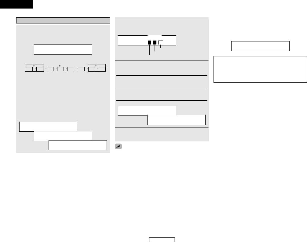
2System setup / Configuration système
Speaker Configuration 
 page 38, 39
*Front Large
*Center Small
*Surr. Small
*S.Back Small
*S.Back 2sp>
*Subwoofer Yes
Delay Time 
 page 39, 40
*Front L 12ft
*Front R 12ft
*Center 12ft
*Surr.L 10ft
*Surr.R 10ft
*S.Back L 10ft
*S.Back R 10ft
*SWubwoofer 12ftYes
Subwoofer Mode
page 40
Crossover Frequency
*SW Mode Norm
*Cr.Over 80Hz
Test Tone 
 page 41
*TEST TONE Yes<
Digital In Assignment 
 page 42
*COAX1 CD
*COAX2 AUX
*OPT1 DVD
*OPT2 TV
Video Input Mode 
 page 42
*DVD Auto
*TV Auto
*VCR Auto
Audio Delay 
 page 43
*A.Delay 0ms
Auto Surround Mode 
 page 43
*Auto Surr. ON
Ext. In Subwoofer Level 
 page 43
*Ext.In SW+15dB
Power Amp Assignment 
 page 43
*P.Amp S.Back
ENGLISH
Getting Started
Thank you for choosing the DENON AVR-686 A/V Surround Receiver. This remarkable component has been engineered to provide superb surround sound listening with home theater sources, such as DVD, as well as providing outstanding high fidelity reproduction of your favorite music sources.
As this product is provided we recommend with an immense array of features, before you begin hookup and operation that you review the contents of this manual before proceeding.
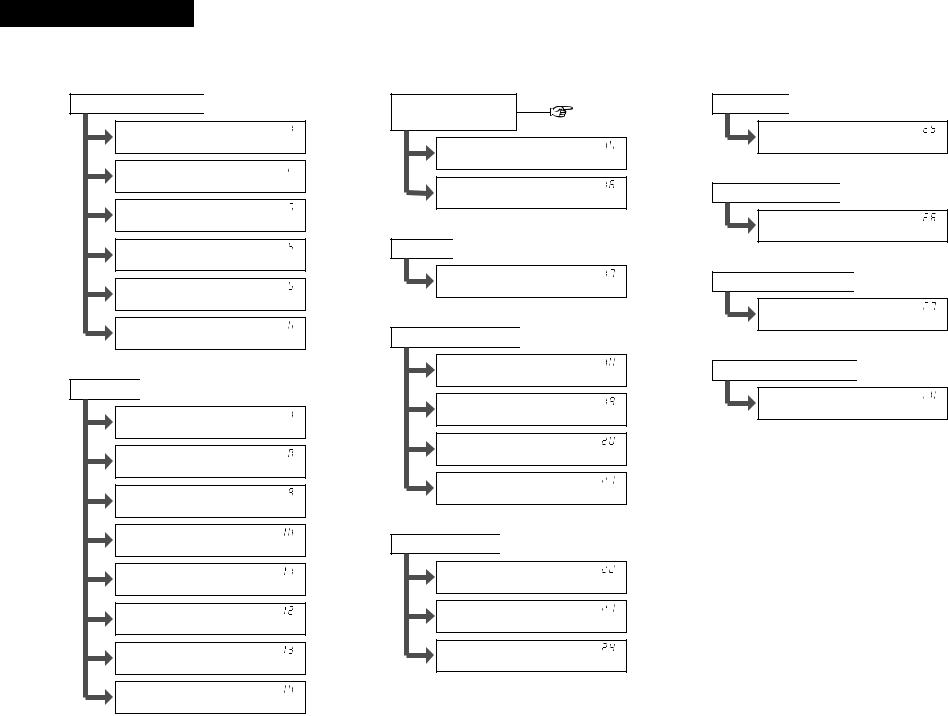
Contents
Getting Started
Accessories ··············································································2
Before using·············································································2
Cautions on installation ·························································2
Cautions on handling······························································2
Preparing the remote control unit ········································2
Inserting the batteries ····························································3
Operating range of the remote control unit ························3
Part names and functions
Front panel··············································································3 Remote control unit································································4
Easy Setup and Operation
Easy setup flow ·······································································4
Speaker system layout ···························································5
Speaker connections ··························································5, 6
Connecting a DVD player and monitor TV···························7
Auto Setup
Connecting a microphone ······················································8
Turning on the power ·····························································8
Starting Auto Setup ································································9
About error messages··························································10 Playing a DVD with surround sound ··································10
Connecting Other Sources
Cable indications···································································11
The video conversion function ············································11
Connecting a TV/DBS tuner ················································12
Connecting a video camera or video game························12
Connecting the external inputs (EXT. IN) terminals··········12
Connecting a CD player························································12
Connecting a VCR ·································································13
Connecting a tape deck, CD recorder or MD recorder ······13
Connecting the antenna terminals ·······························13, 14
Connecting the MULTI ZONE terminals
ZONE2 speaker out connections··········································14 Connecting the power supply cord·····································15
Basic Operation
Playback
Playing the input source ·······················································16
Playback using the external input (EXT. IN) terminals ··········16
Turning the sound off temporarily (MUTING) ·······················16
Listening over headphones ··················································17
Combining the currently playing sound with the
desired image (VIDEO SELECT) ···········································17
Selecting the front speakers ················································17
Checking the currently playing program source···················17 Input mode ·····································································17, 18
Surround
Playing audio sources (CDs and DVDs)
2-channel playback modes ···················································18
Dolby Pro Logic IIx (Pro Logic II) mode ·························19, 20 DTS NEO:6 mode···························································21, 22 Dolby Digital mode and DTS surround···························22, 23 Night mode···········································································24 Adjusting the audio delay ·····················································24
DENON original surround modes
Surround modes and their features······································25 DSP surround simulation················································26, 27 Tone control setting
•Adjusting the sound quality·············································28
•Tone defeat mode ···························································28
Channel Level ·······································································28
Listening to the radio
Auto preset memory ····························································29
Auto tuning ···········································································29
Manual tuning·······································································30 Preset stations······································································30 Recalling preset stations ······················································30
Getting Started
Advanced Operation
Remote control unit
Operating DENON audio components ·································31
Preset memory·····································································32 Operating a component stored in the
preset memory·······························································32~34 Punch through ······································································34
Multi zone music entertainment system ···························35
Remote control unit operations during
multi-source playback ···························································36
Other functions
Recording the program source
(recording the source currently being monitored) ················37
Last function memory ··························································37
Initialization of the microprocessor·······································37
Advanced Setup
Front display··········································································38
System Setup
Setting the Speaker Configuration ·································38, 39 Setting the Delay Time ···················································39, 40 Setting the Subwoofer Mode and
Crossover Frequency····························································40 Setting the Test Tone ···························································41
Setting the Digital In Assignment·········································42 Setting the Video Input Mode ··············································42
Setting the Audio Delay························································43 Setting the Auto Surround Mode ·········································43
Setting the Ext. In Subwoofer Level ····································43
Setting the Power Amp Assignment····································43
System setup items and default values ·····························44
Troubleshooting ····································································45
Additional information···················································46~51
Specifications ········································································52
List of preset codes ····································End of this manual
1
ENGLISH
Getting Started
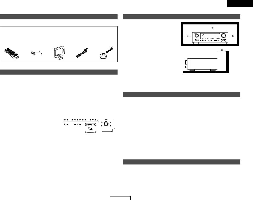
Accessories
Check that the following parts are included in addition to the main unit:
q Operating instructions |
............................ |
1 |
t R6P/AA batteries .................................... |
2 |
w Warranty ................................................. |
|
1 |
y AM loop antenna .................................... |
1 |
e Service station list .................................. |
|
1 |
u FM indoor antenna ................................. |
1 |
r Remote control unit (RC ...............-1001) |
1 |
i Omnidirectional microphone................... |
1 |
|
r |
t |
y |
u |
i |
Before using
Pay attention to the following before using this unit:
•Moving the unit
To prevent short-circuits or damaged wires in the connection cables, always unplug the power supply cord and disconnect the connection cables between all other audio components when moving the unit.
•Before turning the power switch on
Check once again that all connections are correct and that there are not problems with the connection cables. Always set the power switch to the standby position before connecting and disconnecting connection cables.
•Store these instructions in a safe place.
After reading, store this instructions along with the warranty card in a safe place.
•Note that the illustrations in these instructions may differ from the actual unit for explanation purposes.
•V. AUX terminals
The AVR-686’s front panel is equipped with V. AUX terminals. Remove the cap covering the terminals when you want to use them.
|
ENGLISH |
|
|
Getting Started |
|
Cautions on installation |
|
|
Noise or disturbance of the picture may be |
|
|
generated if this unit or any other electronic |
Note |
|
equipment using microprocessors is used |
||
|
||
near a tuner or TV. |
|
|
If this happens, take the following steps: |
|
|
• Install this unit as far away as possible |
|
|
from the tuner or TV. |
|
|
• Run the antenna wires from the tuner or |
|
|
TV away from this unit’s power supply cord |
|
|
and input/output connection cables. |
|
|
• Noise or disturbance tends to occur |
|
|
particularly when using indoor antennas or |
|
|
300 Ω /ohm feeder wires. We recommend |
Wall |
|
using outdoor antennas and 75 Ω /ohm |
||
|
||
coaxial cables. |
|
Note:
For heat dispersal, do not install this unit in a confined space such as a bookcase or similar enclosure.
Cautions on handling
•Switching the input source when input terminals are not connected.
A clicking noise may be produced if the input source is switched when nothing is connected to the input terminals. If this happens, either turn down the MASTER VOLUME control knob or connect components to the input terminals.
•Muting of PRE OUT terminals, PHONES jack and SPEAKER terminals.
The PRE OUT terminals, PHONES jack and SPEAKER terminals include a muting circuit. Because of this, the output signals are greatly attenuated for several seconds after the power switch is turned on or the input source, surround mode or any other set-up is changed. If the volume is turned up during this time, the output will be very high after the muting circuit stops functioning. Always wait until the muting circuit turns off before adjusting the volume.
•Whenever the power switch is in the STANDBY state, the unit is still connected to AC line voltage.
Please be sure to turn off the power switch or unplug the cord when you leave home for, say, a vacation.
Preparing the remote control unit
The included remote control unit (RC-1001) can be used to operate not only the AVR-686 but other remote control compatible DENON components as well. In addition, the memory contains control signals for other remote control units, so it can be used to operate non-DENON remote control compatible products.
2
ENGLISH
ENGLISH
Getting Started
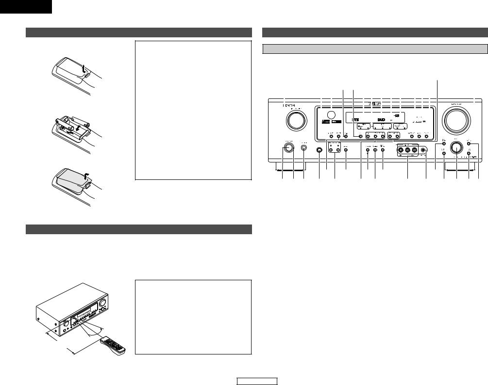
Inserting the batteries
qRemove the remote control unit’s rear cover.
wSet two R6P/AA batteries in the battery compartment in the indicated direction.
e Put the rear cover back on.
Notes on batteries:
•Replace the batteries with new ones if the set does not operate even when the remote control unit is operated nearby the unit. (The included batteries are only for verifying operation.)
•When inserting the batteries, be sure to do so in the proper direction, following the “<” and “>” marks in the battery compartment.
•To prevent damage or leakage of battery fluid:
•Do not use a new battery together with an old one.
•Do not use two different types of batteries.
•Do not short-circuit, disassemble, heat or dispose of batteries in flames.
•If the battery fluid should leak, carefully wipe the fluid off the inside of the battery compartment and insert new batteries.
•When replacing the batteries, have the new batteries ready and insert them as quickly as possible.
Operating range of the remote control unit
•Point the remote control unit at the remote sensor on the main unit as shown in the diagram.
•The remote control unit can be used from a straight distance of approximately 23 feet from the main unit, but this distance will be shorter if there are obstacles in the way or if the remote control unit is not pointed directly at the remote sensor.
•The remote control unit can be operated at a horizontal angle of up to 30 degrees with respect to the remote sensor.

 30° 30°


Approx. 23 feet
NOTE:
•It may be difficult to operate the remote control unit if the remote sensor is exposed to direct sunlight or strong artificial light.
•Do not press buttons on the main unit and remote control unit simultaneously. Doing so may result in malfunction.
•Neon signs or other devices emitting pulsetype noise nearby may result in malfunction, so keep the set as far away from such devices as possible.
Getting Started
Part names and functions
Front panel
For details on the functions of these parts, refer to the pages given in parentheses ( ).
|
|
@7 |
@2 @0 |
|
|
|||||||||||||||||||||||||
#3 |
#2#1#0@9@8 |
@6@5@4 @3 |
@1 |
!9 |
||||||||||||||||||||||||||
|
|
|
|
|
|
|
|
|
|
|
|
|
|
|
|
|
|
|
|
|
|
|
|
|
|
|
|
|
|
|
|
|
|
|
|
|
|
|
|
|
|
|
|
|
|
|
|
|
|
|
|
|
|
|
|
|
|
|
|
|
|
|
|
|
|
|
|
|
|
|
|
|
|
|
|
|
|
|
|
|
|
|
|
|
|
|
|
|
|
|
|
|
|
|
|
|
|
|
|
|
|
|
|
|
|
|
|
|
|
|
|
|
|
|
|
|
|
|
|
|
|
|
|
|
|
|
|
|
|
|
|
|
|
|
|
|
|
|
|
|
|
|
|
|
|
|
|
|
|
|
|
|
|
|
|
|
|
|
|
|
|
|
|
|
|
|
|
|
|
|
|
|
|
|
|
|
|
|
|
|
|
|
|
|
|
|
|
|
|
|
|
|
|
|
|
|
|
|
|
|
|
|
|
|
|
|
|
|
|
|
|
|
|
|
|
|
|
|
|
|
|
|
|
|
|
|
|
|
|
|
|
|
|
|
|
|
|
|
|
|
|
|
|
|
|
|
|
t |
q w e r y |
uo !1 i !0
!4 |
!2 !3 !5!6!7!8 |
q Power ON/STANDBY switch ················(8)
w Power indicator······································(8)
e Power switch ···································(8, 37) r Headphones jack (PHONES) ···············(17)
t ANALOG button···································(18)
y SPEAKER A/B buttons ··················(17, 37) u ZONE2 button ······································(35)
i Preset station select buttons ·······(29, 30) o STANDARD/NIGHT button ···········(19~24)
!05CH/7CH STEREO button ···················(25)
!1DIRECT/STEREO button······················(18)
!2V. AUX INPUT terminals ·····················(12)
!3SETUP MIC jack ·····································(8)
!4SURROUND MODE button ·················(16)
!5SURROUND PARAMETER
button ···················································(19)
!6SELECT knob····························(16, 19, 28)
!7TONE DEFEAT button··························(28)
!8TONE CONTROL button······················(28)
!9MASTER VOLUME control knob ········(16)
@0TUNING •(up)/ª(down) buttons ·····(29)
@1STATUS button ······························(17, 23)
@2DIMMER button ···································(17)
@3VIDEO SELECT button·························(17)
@4OUTPUT indicator································(22)
@5Master volume indicator·····················(16)
@6Display
@7INPUT mode indicator·························(18)
@8SIGNAL indicator ·································(18)
@9BAND button ········································(29)
#0EXT. IN button······································(16)
#1Remote control sensor··························(3)
#2INPUT MODE button ···························(17)
#3INPUT SELECTOR knob·······················(16)
3
ENGLISH

ENGLISH
Getting Started
Remote control unit
For details on the functions of these parts, refer to the pages given in parentheses ( ).
Easy Setup and Operation
|
Remote control signal |
• |
steps necessary to configure the AVR-686 according to your |
|
|
|
and the source equipment and loudspeakers you are using. |
||
Indicator ···············(32, 34) |
transmitter···················(3) |
|
||
• |
we recommend using the Auto Setup function. |
|
||
|
|
|
||
|
Power buttons |
• |
various settings manually without using Auto Setup ( |
page 38 ~ |
|
································(8, 33) |
|
|
|
ZONE2 buttons····(34, 36) |
MAIN buttons |
|
Easy setup flow |
|
|
|
|
||
MODE |
································(4, 34) |
|
|
|
|
|
|
|
|
·················(16, 26) |
|
|
Placing the speakers. |
|
|
|
|
|
|
source selector
·················(16, 32)
buttons
SETUP/SETUP
···················(33, 38)
buttons
19, 33)
············(17, 23, 33)
TONE button
SELECT button |
mode selector
················(16~18)
MEMO
Tuner system/System buttons·················(29, 34)
Mode selector switches
································(8, 31)
Master volume control buttons·················(16, 36)
MUTING button
····································(16)
SURROUND PARAMETER/System button···················(19, 33)
CH SELECT/ENTER button ·····················(20, 28)
SURROUND BACK/ RETURN button···(22, 33)
SPEAKER button
································(8, 17)
DIMMER button
····································(17)
•The Dolby Surround Pro Logic II(x) Cinema or Music mode can be chosen directly by pressing the CINEMA or MUSIC button on the remote control unit during playback in the Dolby Surround Pro Logic II(x) mode.
•The DTS NEO:6 Cinema or Music mode can be chosen directly by pressing the CINEMA or MUSIC button on the remote control unit during playback in the DTS NEO:6 mode.
• The main zone output can be turned on and off with the MAIN button. |
4 |
|
Connecting the
speakers.
Connecting a monitor and a DVD player.
Starting the Auto
Setup.
Playing a DVD with surround sound.
Auto setup flow
Connecting a microphone.
Measurement of the speakers in the listening position.
Check of the measurement result.
result in the memory.
ENGLISH
ENGLISH
Easy Setup and Operation
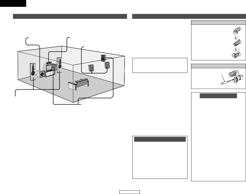
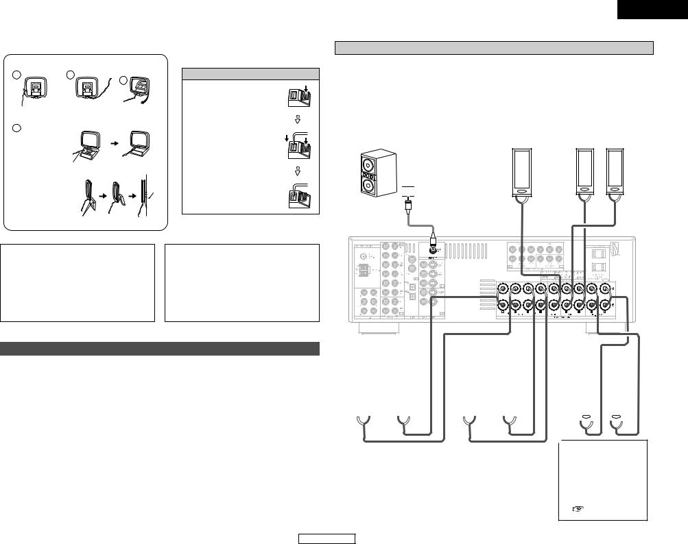
Speaker system layout
2Basic system layout
The following is an example of the basic layout for a system consisting of eight speaker systems and a television monitor:
Subwoofer |
Center speaker system |
Surround back speaker systems
Front speaker systems
Set these at the sides of the TV
or screen with their front surfaces  Surround speaker systems as flush with the front of the
screen as possible.
Speaker connections
•Connect the speaker terminals with the speakers making sure that like polarities are matched (< with <, > with >). Mismatching of polarities will result in weak central sound, unclear orientation of the various instruments, and the stereo image being impaired.
•When making connections, take care that none of the individual conductors of the speaker cable come in contact with adjacent terminals, with other speaker cable conductors, or with the rear panel.
NOTE:
NEVER touch the speaker terminals when the power is on. Doing so could result in electric shocks.
2Speaker impedance
•When speaker systems A and B are used
separately, speakers with an impedance of 6 to 16 Ω /ohms can be connected for use as front speakers.
•Be careful when using two pairs of front speakers (A + B) at the same time, since
speakers with an impedance of |
12 |
to |
16 |
|
Ω |
/ohms in this case must be used. |
|
|
|
• Speakers with an impedance of |
6 |
to |
16 |
|
Ω |
/ohms can be connected for use as center |
|||
and surround and surround back speakers.
•The protector circuit may be activated if the unit is operated for long periods of time at high volumes when speakers with an impedance lower than the specified impedance are connected.
Note on speaker impedance
The protector circuit may be activated if the unit is operated for long periods of time at high volumes when speakers with an impedance lower than the specified impedance (for example speakers with an impedance of less than 4 Ω /ohms) are connected. If the protector circuit is activated, the speaker output is cut off. Turn off the unit’s power, wait for the unit to cool down, improve the ventilation around the unit, then turn the power back on.
5
Easy Setup and Operation
Connecting the speaker cables
1. Loosen by turning counterclockwise.
2. Insert the cable.
3. Tighten by turning clockwise.
Connecting banana plugs
Banana plug
Turn clockwise to tighten, then insert the banana plug.
Protector circuit
This unit is equipped with a high-speed protection circuit. The purpose of this circuit is to protect the speakers under circumstances such as when the output of the power amplifier is inadvertently short-circuited and a large current flows, when the temperature surrounding the unit becomes unusually high, or when the unit is used at high output over a long period which results in an extreme temperature rise.
When the protection circuit is activated, the speaker output is cut off and the power supply indicator flashes. Should this occur, please follow these steps: be sure to switch off the power of this unit, check whether there are any faults with the wiring of the speaker cables or input cables, and wait for the unit to cool down if it is very hot. Improve the ventilation condition around the unit and switch the power back on.
If the protection circuit is activated again even though there are no problems with the wiring or the ventilation around the unit, switch off the power and contact a DENON service center.
ENGLISH
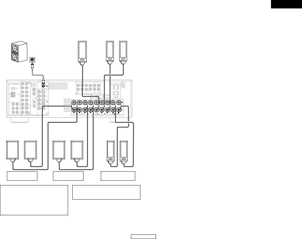
Easy Setup and Operation
2Connections
When making connections, also refer to the operating instructions of the other components.
Subwoofer |
|
Center |
|
Surround speaker |
|
speaker |
|
systems |
|
|
|
|
||
|
|
|
|
|
Connection terminal for a subwoofer with built-in amplifier.

 To achieve Dolby Digital playback effect, use a unit that can sufficiently reproduce frequencies of under 80 Hz.
|
|
(L) |
|
(R) |
IN |
|
|
|
|
> |
< |
> |
< > |
< |
|
|
|
(L) |
(R) |
(L) |
(R) |
(L) |
(R) |
< > |
> < |
< > |
> |
< |
< > < |
|
|
|
|
> |
|
Front speaker |
Front speaker |
Surround back |
|||
systems (B) |
systems (A) |
speaker systems |
|||
Precautions when connecting speakers:
If a speaker is placed near a TV or video monitor, the colors on the screen may be disturbed by the speaker’s magnetism. If this should happen, move the speaker away to a position where it does not cause this effect.
NOTE:
•When using only one surround back speaker, connect it to the left channel.
6
ENGLISH
Easy Setup and Operation
ENGLISH
ENGLISH
Easy Setup and Operation
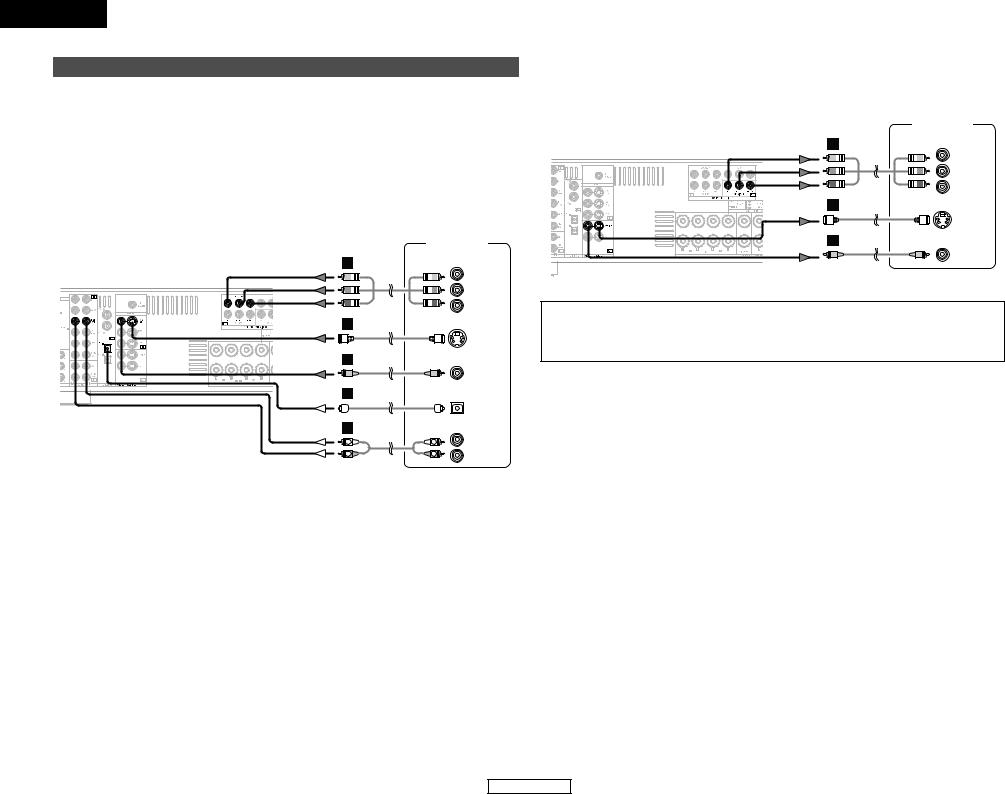
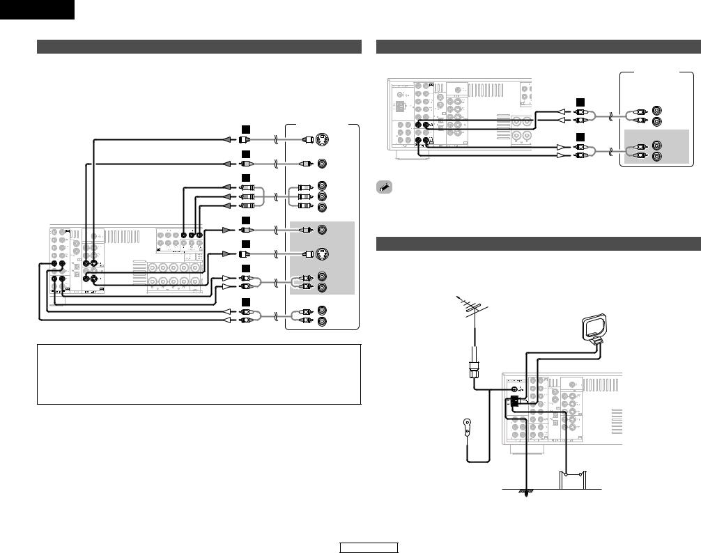
Connecting a DVD player and monitor TV
•To connect the video output from the DVD player to the AVR-686, you only need to choose one connection type. Component video connection offers the best quality (and is required for progressive DVD playback), followed by S-Video, while composite video offers the lowest picture quality of the three connection types. For more information about the video up conversion function (  page 11).
•To connect the digital audio output from the DVD player, you can choose from either the coaxial or optical connections. If you choose to use the coaxial connection, it needs to be assigned. For more information about Digital Input Assignment (  page 42).
•Connect a non-DVD video disc player (such as a laser disc, VCD/SVCD, or future high definition disc player) to the DVD/VDP terminals in the same way.
|
DVD player |
|
H |
COMPONENT VIDEO OUT |
|
|
|
|
|
|
Y |
|
|
PB |
|
|
PR |
G |
|
|
|
|
S VIDEO |
|
|
OUT |
F |
|
VIDEO |
|
|
|
|
|
OUT |
D |
|
|
|
|
OPTICAL |
|
|
OUT |
A |
|
AUDIO OUT |
L |
L |
L |
|
||
R |
R |
R |

 Audio signal flow is shown with white arrows; video signal flow is shown with gray arrows.
Easy Setup and Operation
•For best picture quality (especially with progressive DVD and other high definition sources), choose the component video connection to your monitor TV. S-Video and composite video outputs are also provided if your TV does not have component video inputs.
|
Monitor TV |
H |
COMPONENT VIDEO IN |
|
|
|
Y |
|
PB |
|
PR |
G |
|
|
S VIDEO |
|
IN |
F |
VIDEO |
|
|
|
IN |
NOTE:
•The component video input and/or output terminals may be labeled differently on some TVs, monitors or video components (Y, PB, PR; Y, CB, CR; Y, B-Y, R-Y). Check the owner’s manuals for the other components for further information.
7
ENGLISH
Easy Setup and Operation
 ON/SOURCE
POWER SPEAKER A
ON/STANDBY |
SETUP MIC |
Setup
Setup function of this unit performs an analysis of the system to permit an appropriate automatic setting.
and setting details
sets the speaker connection, polarity, and bass ability.
sets the delay time from each speaker corresponding to listening position.
sets the volume that is output from each speaker.
For accurate measurements
•Keep quiet during the auto setup procedure. It is recommended that you turn off the power of any air-conditioner, projector or other equipment that may produce noise.
•Do not stand between the microphone and speakers while Auto Setup is performed.
•Do not place any obstacles between the microphone and speakers. Also, be sure to point the speakers towards the listening position.
NOTE:
•A loud test tone is output during the measurement. Please consider this should you be planning night time measurements, and consider not allowing small children into the listening room at this time.
•The Auto Setup is not displayed when “MUTING”, “HEADPHONE ONLY” is selected.
MODE 1 |


 CURSOR


 SPEAKER
Connecting a microphone
1 Connect the microphone for Auto Setup to the SETUP MIC jack on the front panel of the unit.
2 Place the microphone for Auto Setup at the actual listening position which will be at the same height as your ears.
Microphone

 Place the microphone on a tripod or level surface.
8
ENGLISH
Easy Setup and Operation
Turning on the power
1 Turn on your subwoofer.
2 Turn on your monitor (TV).
3 Press the POWER switch.
¢ ON:
The power turns on and the indicator lights.
Set the POWER switch to this position to turn the power on and off from the included remote control unit.
£ OFF:
The power turns off and the indicator is off.
In this position, the power cannot be turned on and off from the remote control unit.
4 Press the ON/STANDBY switch on the main unit or ON/SOURCE button on the remote control unit.
• Turn on the power.
5 Press the SPEAKER A button to turn the speakers on.
Set the MODE 1 switch to “AUDIO” (only when operating with the remote control unit).
ENGLISH
ENGLISH
Easy Setup and Operation
Starting Auto Setup
1 Press the CURSOR F button to start the Auto
Setup.
• Start the measurements.
Auto Set <Start

 Measurement of each channel is performed as follows:
|
1 |
|
2 |
|
|
|
3 |
FL |
FR |
C |
SW |
SL |
SR |
SBL |
SBR |

 1: Only the front speakers (A) are measured, front speakers
(B) are not available. Even if the front speakers (B) are set, the setting automatically switches to the front speakers (A) once measurements are completed.

 2: The subwoofer speaker is measured twice.

 3: When “ZONE2” is selected, this is not displayed (
 page 43).
After each channel is measured, “Calculating” appears. The display switches to the speaker check display automatically.
Measure:FL <Ccl
Calculating
Speaker:3/4/.1
2Check the results of the speaker detection
Example: 7.1-channel systems
Speaker:3/4/.1
Subwoofer
Surround and Surround back speaker
Front and Center speaker
2 Press the CURSOR D or H button to select “Store”, then press the CURSOR F button.
Store:
Store the checked measurement values.
All parameters are stored.
Cancel:
Cancel the checked measurement values.
Setup <Store
Storing
Disconnect the setup mic to finish Auto Setup.
•Measurement is cancelled if the MASTER VOLUME control knob is operated while the Auto Setup is performed.
•If the output volume and crossover frequency of your subwoofer speaker can be changed, then set the volume to halfway and the crossover filter to maximum or switch off the low-pass filter.
•The speaker configuration, delay time and channel level measurement values can be checked using the system setup function (  page 38 ~ 41).
Easy Setup and Operation
2About automatic retry
To confirm the results of the measurements, remeasurement is automatically performed.
Remeasurement is performed up to 2 times. During this time, “Retry1” or “Retry2” is displayed on the display.
Overload Retry1
NOTE:
•When measurements have been made using the measurement microphone, speakers with built-in filters, such as a subwoofer, might be set to a value that differs from the physical distance because of the internal electrical delay.
9
ENGLISH
Easy Setup and Operation
About error messages
•These error displays may be displayed when performing Auto Setup measurement and the automatic measurements can not be completed because of the speaker arrangement, measurement environment, or other factors. Please check the following matters, reset the pertinent items, and measure again.
•When there is too much noise in the room, the speakers may not be detected properly. Should this happen, perform the measurements when the noise level is low, or switch off the power of the equipment that is producing the noise for the duration of the measurements.
Press the CURSOR D or H button to select the items, then press the CURSOR F button.
|
Display example |
|
|
Cause |
Measures |
|
|
|
|
|
q The speakers required for producing suitable |
• Check that the pertinent speakers |
|
|
|
|
|
reproduction have not been detected. |
are properly connected. |
|
|
|
|
|
• The front L or front R speaker was not |
|
|
|
|
|
|
|||
|
Caution:SP None |
|
properly detected. |
|
||
|
|
• Only one channel of the surround speakers |
|
|||
|
|
|
|
|
||
|
|
|
|
was detected. |
|
|
|
|
|
|
• Sound was output from the R channel when |
|
|
|
|
|
|
|||
|
FL |
|
|
only one |
surround back speaker was |
|
|
|
|
connected. |
|
|
|
|
|
|
|
|
|
|
|
|
|
|
|
||
|
|
|
|
• The surround back speaker was detected, but |
|
|
|
|
|
|
the surround speaker was not detected. |
|
|
|
|
|
|
|
|
|
|
|
|
|
w The speaker polarity is connected in reverse. |
• Check the polarity of the pertinent |
|
|
|
|
||||
|
Caution |
:Phase |
|
|
|
speakers. For some speakers, this |
|
|
|
|
display may be displayed even |
||
|
|
|
|
|
|
|
|
|
|
|
|
|
though the speakers are properly |
|
|
|
|
|
|
connected. If so, select “Skip0”. |
|
FL/R |
|
|
|
|
|
|
|
|
|
|
|
|
|
|
|
|
|
|
|
|
|
|
|
|
|
|
|
|
|
|
e When accurate measurements cannot be |
• Set up the speakers so that their |
|
|
|
|
||||
|
Caution |
|
made due to the input level of the microphone |
position is farther away from the |
||
|
|
being too high. |
listening position. |
|||
|
|
|
|
|||
|
|
|
|
|
|
• Lower the volume of the subwoofer |
|
|
|
|
|
|
speaker. |
|
Overload |
<Exit |
|
|
|
|
|
|
|
|
|
||
|
|
|
|
|
|
|
|
|
|
|
|
|
|
ENGLISH
Easy Setup and Operation
Playing a DVD with surround sound
1 Disconnect the microphone from the unit.
2 Select the input source to be played.
3 Select the play (surround) mode.
4 Start DVD playback.
5 Adjust the volume.
10
ENGLISH
ENGLISH
Connecting Other Sources
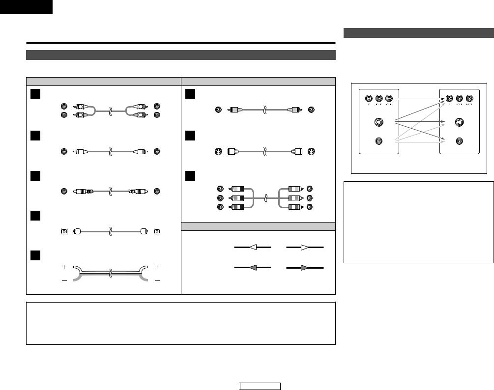
Cable indications
The hookup diagrams on the subsequent pages assume the use of the following optional connection cables (not supplied).
|
|
Audio cable |
|
|
Video cable |
|
|
|
A |
Analog terminal (Stereo) |
|
F |
Video terminal |
|
|
|
|
|
(White) |
L |
L |
(Yellow) |
|
|
|
|
|
(Red) |
|
|
|
|
|
||
|
R |
R |
|
Video cable (75 Ω |
|
|
|
|
|
|
Pin-plug cable |
|
|
/ohm video pin-plug cable) |
|
||
|
|
|
|
|
|
|
|
|
B |
Analog terminal (Monaural, for subwoofer) |
G |
S-Video terminal |
|
|
|
||
|
|
Pin-plug cable |
|
|
S-Video cable |
|
|
|
C |
Digital terminal (Coaxial) |
|
H |
Component video terminal |
|
|
||
|
(Orange) |
|
|
|
(Green) |
|
|
(Y) |
|
|
|
|
|
|
|
|
|
|
|
Coaxial cable (75 Ω /ohm pin-plug cable) |
|
(Blue) |
|
|
(PB/CB) |
|
|
|
|
(Red) |
|
|
(PR/CR) |
||
D |
|
|
|
|
|
|
||
Digital terminal (Optical) |
|
|
Component video cable |
|
||||
|
|
|
|
|
Signal direction |
|
|
|
|
|
Optical cable (Optical fiber cable) |
|
Audio signal |
|
|
|
|
|
|
|
|
|
|
|
|
|
E |
Speaker terminal |
|
|
IN |
OUT |
OUT |
IN |
|
|
|
|
|
|
Video signal |
|
|
|
|
|
|
|
|
IN |
OUT |
OUT |
IN |
|
|
Speaker cable |
|
|
|
|
|
|
NOTE:
•Do not plug in the power supply cord until all connections have been completed.
•When making connections, also refer to the operating instructions of the other components.
•Be sure to connect the left and right channels properly (left with left, right with right).
•Note that binding pin-plug cables together with power supply cords or placing them near a power transformer will result in hum or other noise.
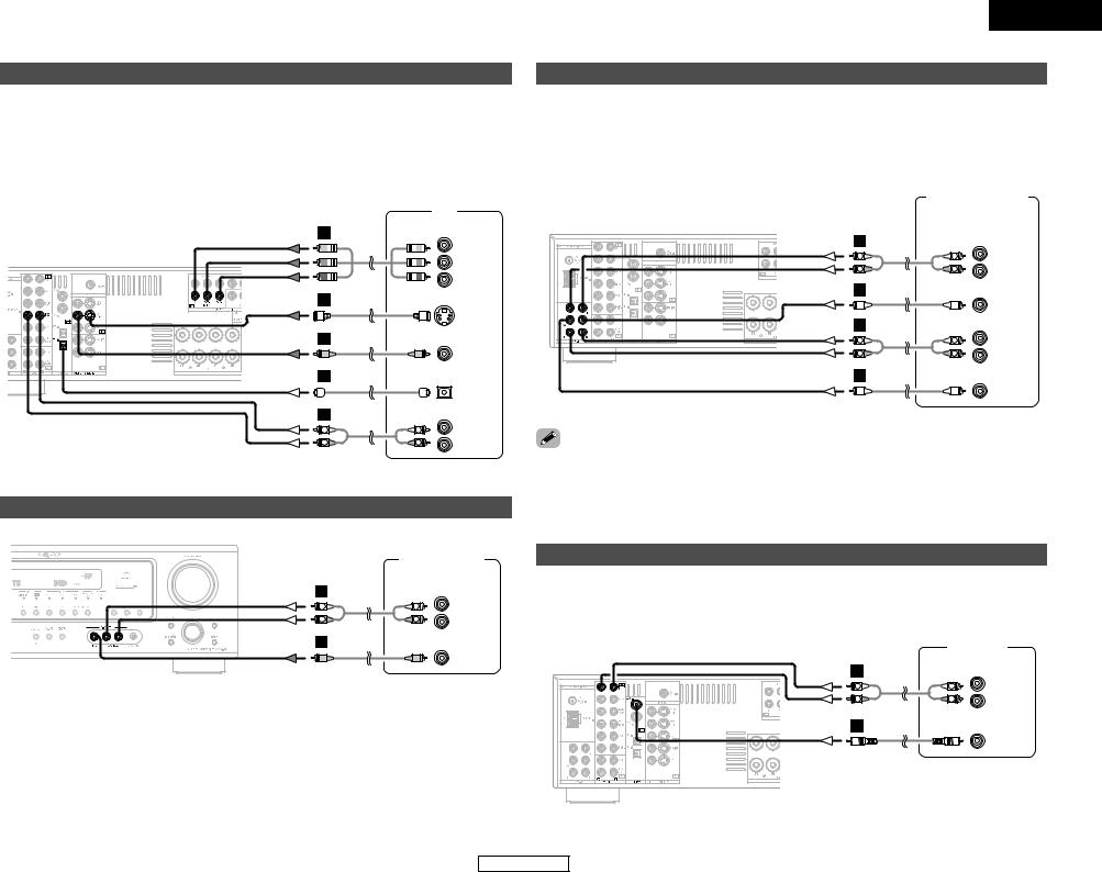
Connecting Other Sources
The video conversion function
With the AVR-686, the Video signal and the S-Video signal which were inputted are mutually converted. And also the Video signal and the S-Video signal which were inputted are converted into a higher quality.
The flow of the video signals.
(Component video |
(Component video |
terminals) |
terminals) |
(S-Video terminal) |
(S-Video terminal) |
(Video terminal) |
(Video terminal) |
This unit’s input |
This unit’s output |
terminals |
terminals |
Cautions on the video conversion function:
When the component video terminals are used to connect the AVR-686 with a TV (or monitor, projector, etc.) and the video (yellow) or S-Video terminals are used to connect the AVR-686 with a VTR, depending on the combination of the TV and VTR the picture may flicker in the horizontal direction, be distorted, be out of sync not display at all when playing video tapes.
If this happens, connect a commercially available video stabilizer, etc., with a TBC (time base corrector) function between the AVR-686 and the VTR, or if your VTR has a TBC function, turn it on.
11
ENGLISH
Connecting Other Sources
Connecting a TV/DBS tuner
•For best picture quality choose the component video connection to your TV or DBS tuner. S-Video and composite video inputs are also provided if your TV or DBS tuner does not have component video outputs.
•To connect the digital audio output from the TV or DBS tuner, you can choose from either the coaxial or optical connections. If you choose to use the coaxial connection, it needs to be assigned. For more information about Digital Input Assignment (  page 42).
|
|
TV |
H |
COMPONENT VIDEO OUT |
|
|
|
|
|
|
Y |
|
|
PB |
|
|
PR |
G |
|
|
|
|
S VIDEO |
|
|
OUT |
F |
|
VIDEO |
|
|
|
|
|
OUT |
D |
|
|
|
|
OPTICAL |
|
|
OUT |
A |
|
AUDIO OUT |
L |
L |
L |
R |
R |
R |
Connecting a video camera or video game
|
Video camera / |
|
|
Video game |
|
A |
|
AUDIO OUT |
L |
L |
L |
R |
R |
R |
F |
|
|
|
|
VIDEO |
|
|
OUT |
ENGLISH
Connecting Other Sources
Connecting the external inputs (EXT. IN) terminals
•These terminals are for inputting multi-channel audio signals from an external decoder, or a component with a different type of multi-channel decoder, such as a DVD Audio player, a multichannel Super Audio CD player, or another future multi-channel sound format decoder.
•The video signal connection is the same as that for a DVD player.
•For instructions on playback using the external input (EXT. IN) terminals (  page 16).
|
DVD Audio-Video / |
||
|
Super Audio CD player / |
||
|
External decoder |
||
A |
5.1ch AUDIO OUT |
||
|
|
FRONT |
|
L |
L |
L |
|
R |
R |
R |
|
B |
|
|
|
|
|
CENTER |
|
A |
|
SURROUND |
|
L |
L |
||
L |
|||
R |
R |
R |
|
B |
|
SUB- |
|
|
|
||
|
|
WOOFER |
|
discs on which special copyright protection measures have been taken, the digital signals not be output from the DVD player. In this case, connect the DVD player’s analog multioutput to the AVR-686’s EXT. IN terminals for playback. Also refer to your DVD player’s
instructions.
Connecting a CD player
To connect the digital audio output from the CD player, you can choose either coaxial or optical connection. If you choose to use the optical connection, it needs to be assigned. For more information about Digital Input Assignment (  page 42).
|
|
CD player |
A |
|
AUDIO OUT |
|
|
|
L |
L |
L |
|
||
R |
R |
R |
C
COAXIAL
OUT
12
ENGLISH
ENGLISH
Connecting Other Sources
Connecting a VCR
•For best picture quality choose the component video connection to your VCR. S-Video and composite video outputs are also provided.
•If you wish to perform analog dubbing from a digital source, such as a DVD recorder to an analog recorder such as a cassette deck, you will need to connect the analog inputs and outputs as shown below, in addition to the digital audio connections.
Video deck
G
S VIDEO
OUT
F
VIDEO
OUT
H |
COMPONENT VIDEO OUT |
|
|
|
Y |
|
|
PB |
|
|
PR |
F |
|
VIDEO |
|
|
|
|
|
IN |
G |
|
|
|
|
S VIDEO |
|
|
IN |
A |
|
AUDIO IN |
|
|
|
L |
L |
L |
R |
R |
R |
A |
|
AUDIO OUT |
|
|
|
L |
L |
L |
|
||
R |
R |
R |
NOTE:
•When recording to a VCR recorder, it is necessary that the type of cable used with the playback source equipment be the same type that is connected to the AVR-686 VCR OUTPUT terminal.
Example: VCR IN → |
S-Video cable : VCR OUT → |
S-Video cable |
VCR IN → |
Video cable : VCR OUT → |
Video cable |
Connecting Other Sources
Connecting a tape deck, CD recorder or MD recorder
|
Tape deck / |
|
|
CD recorder / |
|
|
MD recorder |
|
A |
|
AUDIO OUT |
|
|
|
L |
L |
L |
|
||
R |
R |
R |
A |
|
AUDIO IN |
|
|
|
L |
L |
L |
R |
R |
R |
noise is generated, move the tape deck further away from the source of such noise.
Connecting the antenna terminals
An FM antenna cable plug can be connected directly to the unit.
Direction of broadcasting station
FM antenna |
AM loop antenna |
(Supplied) |
75 Ω /ohm COAXIAL cable
FM indoor antenna (Supplied)
Ground |
AM outdoor antenna |
13
ENGLISH
Connecting Other Sources
2AM loop antenna assembly
1 |
2 |
 Remove the vinyl tie and take out the connection line.
4
a. Antenna placed on a stable surface.
Mount
b. Hanging the antenna on a wall.
Connect to the AM antenna terminals.
3
Bend in the reverse direction.
Use the
installation hole to secure the antenna to a wall, etc.
Connection of AM antennas
1. Push the lever.
2. Insert the conductor.
3. Return the lever.
Note to CATV system installer:
This reminder is provided to call the CATV system installer’s attention to Article 820-40 of the NEC which provides guidelines for proper grounding and, in particular, specifies that the cable ground shall be connected to the grounding system of the building, as close to the point of cable entry as practical.
NOTE:
•Do not connect two FM antennas simultaneously.
•Even if an external AM antenna is used, do not disconnect the AM loop antenna.
•Make sure the AM loop antenna lead terminals do not touch metal parts of the panel.
ENGLISH
Connecting Other Sources
ZONE2 speaker out connections
•When the power amplifier is assigned to the ZONE2 output channel at “Power Amp Assignment”, the surround back speaker terminals can be used as the ZONE2 speaker out terminals (  page 35).
•The connections diagram below is an example for when the surround back speaker is assigned to the ZONE2 stereo 2 channel.
In this case, surround back speaker out can not be used for MAIN ZONE.
Subwoofer |
|
Center |
|
Surround speaker |
|
speaker |
|
systems |
|
|
|
|
||
|
|
|
|
|


 IN
IN
Connection terminal for subwoofer with built-in amplifier (subwoofer), etc.
|
|
(L) |
|
(R) |
> |
< |
> |
< > |
< |
|
|
|
Connecting the MULTI ZONE terminals

 For instructions on operations using the MULTI ZONE functions (
  page 35, 36).
|
|
|
|
|
|
|
|
|
|
|
|
|
|
|
|
|
|
|
|
|
|
|
|
|
|
|
|
|
|
|
|
(L) |
|
|
|
(R) |
|
|
|
(L) |
|
|
|
(R) |
|
|
|
|
|
|
|
|
(L) |
|
|
|
|
(R) |
|
|
|
|
|
|
|
|
|
|
|
|
|
|
|
|
|
|
|
|
|
|
|
|
|
|
|
|
|
|
|
|
|
|
|
|
|
|
|
|
|
|
|
|
|
|
|
|
|
|
|
|
|
|
|
|
|
|
|
|
|
< > |
> < |
|
< > |
> |
< |
|
|
|
|
|
|
|
|
|
|
|
|
|
|||||||||||
|
|
|
|
|
|
|
|
|
|
|
|
|
|
||||||||||||||||
|
< > |
|
< |
||||||||||||||||||||||||||
|
|
|
|
|
|
|
|
|
|
|
|
|
|
|
> |
|
|||||||||||||
|
|
|
|
|
|
|
|
|
|
|
|
|
|||||||||||||||||
|
|
|
|
|
|
|
|
|
|
|
|
|
|
|
|
|
|
|
|
|
|
|
|
|
|
|
|
|
|
|
|
Front speaker |
|
|
Front speaker |
|
|
|
|
|
|
ZONE2 speaker |
|||||||||||||||||
|
|
systems (B) |
|
|
systems (A) |
|
|
|
|
|
|
|
|
systems |
|||||||||||||||
|
|
|
|
|
|
|
|
|
|
|
|
|
|
|
|
|
|
|
|
|
|
|
|
|
|
|
|||
|
|
|
|
|
|
|
|
|
|
|
|
|
|
|
|
|
|
|
|
NOTE: |
|
|
|
|
|
||||
|
|
|
|
|
|
|
|
|
|
|
|
|
|
|
|
|
|
|
|
• The settings must be |
|||||||||
|
|
|
|
|
|
|
|
|
|
|
|
|
|
|
|
|
|
|
|
|
changed |
to |
use this |
||||||
|
|
|
|
|
|
|
|
|
|
|
|
|
|
|
|
|
|
|
|
|
speaker |
for |
ZONE2 |
||||||
|
|
|
|
|
|
|
|
|
|
|
|
|
|
|
( |
|
page 43). |
||||||||||||
14
ENGLISH
ENGLISH
Connecting Other Sources
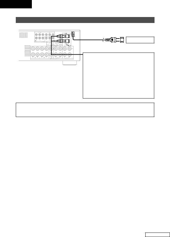
Connecting the power supply cord
AC outlet (Wall)
AC 120 V, 60 Hz
AC OUTLETS
• SWITCHED (total capacity – 120 W (1 A.)) The power to this outlet is turned on and off in conjunction with the POWER switch on the main unit, and when the power is switched between on and standby from the remote control unit.
No power is supplied from this outlet when this unit’s power is at standby. Never connect equipment whose total power consumption exceeds 120 W (1 A.).
NOTE:
•Only use the AC OUTLETS for connecting audio equipment. Never use it for hair driers, TVs or other electrical appliances.
15
Connecting Other Sources
ENGLISH
Basic Operation
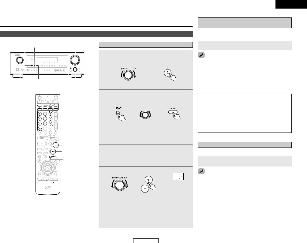
Playback
INPUT MODE ANALOG |
MASTER VOLUME |
EXT. IN
INPUT SELECTOR SURROUND MODE SELECT


 SURROUND
MODE
INPUT SELECTOR 
 VOLUME
MUTING
INPUT MODE 


 EXT. IN
  ANALOG
Playing the input source
1 Select the input source to be played.
Example: CD
(Main unit) |
(Remote control unit) |
2 Select the play (surround) mode.
Example: STEREO
|
SELECT |
(Main unit) |
(Remote control unit) |

 To select the surround mode while adjusting the surround parameters, tone defeat or tone control, press the SURROUND MODE button and then operate the selector.
3 Start playback on the selected component.

 For operating instructions, refer to the component’s manual.
4 Adjust the volume.
|
The volume level is |
|
displayed on the |
|
master volume level |
(Main unit) |
(Remote control unit) display. |

 The volume can be adjusted within the range of –70 to 0 to 18 dB, in steps of 1 dB. However, when the channel level is set as described (
  page 28), if the volume for any channel is set at +1 dB or greater, the volume cannot be adjusted up to 18 dB. (In this case the maximum volume is adjusted to “18 dB — (Maximum value of channel level)”.)
16
ENGLISH
Basic Operation
Playback using the external input (EXT. IN) terminals
The signals being input to the external decoder input terminals are played without passing through the surround circuitry.
Press the EXT. IN button to select the external input.
the external input mode:
the INPUT MODE or ANALOG button to switch to the input mode (  page 17, 18).
external input mode can be set for any input source. To video while listening to sound, select the input source to the video signal is connected, then set this mode. subwoofer output level is too high, set the “SW ATT.”
parameter to “ON”.
NOTE:
•When the input mode is set to the external input (EXT. IN), the play mode (DIRECT, VIRTUAL SURROUND, STEREO, STANDARD (DOLBY/DTS SURROUND), 5CH/7CH STEREO or DSP SIMULATION) cannot be selected.
•In play modes other than the external input mode, the signals connected to the EXT. IN terminals cannot be reproduced. In addition, signals cannot be output from channels not connected to the input terminals.
Turning the sound off temporarily (MUTING)
Use this to turn off the audio output temporarily.
Press the MUTING button.
the MUTING mode:
the MUTING button again.
the VOLUME button on the remote control unit, or the volume up or down via the front panel MASTER
knob.
ENGLISH
 Loading...